WO2020162152A1 - Lattice base material, electrode, and lead storage battery - Google Patents
Lattice base material, electrode, and lead storage battery Download PDFInfo
- Publication number
- WO2020162152A1 WO2020162152A1 PCT/JP2020/001757 JP2020001757W WO2020162152A1 WO 2020162152 A1 WO2020162152 A1 WO 2020162152A1 JP 2020001757 W JP2020001757 W JP 2020001757W WO 2020162152 A1 WO2020162152 A1 WO 2020162152A1
- Authority
- WO
- WIPO (PCT)
- Prior art keywords
- lattice
- frame
- bone
- bones
- base material
- Prior art date
Links
Images


Classifications
-
- H—ELECTRICITY
- H01—ELECTRIC ELEMENTS
- H01M—PROCESSES OR MEANS, e.g. BATTERIES, FOR THE DIRECT CONVERSION OF CHEMICAL ENERGY INTO ELECTRICAL ENERGY
- H01M4/00—Electrodes
- H01M4/02—Electrodes composed of, or comprising, active material
- H01M4/64—Carriers or collectors
- H01M4/70—Carriers or collectors characterised by shape or form
- H01M4/72—Grids
- H01M4/73—Grids for lead-acid accumulators, e.g. frame plates
-
- Y—GENERAL TAGGING OF NEW TECHNOLOGICAL DEVELOPMENTS; GENERAL TAGGING OF CROSS-SECTIONAL TECHNOLOGIES SPANNING OVER SEVERAL SECTIONS OF THE IPC; TECHNICAL SUBJECTS COVERED BY FORMER USPC CROSS-REFERENCE ART COLLECTIONS [XRACs] AND DIGESTS
- Y02—TECHNOLOGIES OR APPLICATIONS FOR MITIGATION OR ADAPTATION AGAINST CLIMATE CHANGE
- Y02E—REDUCTION OF GREENHOUSE GAS [GHG] EMISSIONS, RELATED TO ENERGY GENERATION, TRANSMISSION OR DISTRIBUTION
- Y02E60/00—Enabling technologies; Technologies with a potential or indirect contribution to GHG emissions mitigation
- Y02E60/10—Energy storage using batteries
-
- Y—GENERAL TAGGING OF NEW TECHNOLOGICAL DEVELOPMENTS; GENERAL TAGGING OF CROSS-SECTIONAL TECHNOLOGIES SPANNING OVER SEVERAL SECTIONS OF THE IPC; TECHNICAL SUBJECTS COVERED BY FORMER USPC CROSS-REFERENCE ART COLLECTIONS [XRACs] AND DIGESTS
- Y02—TECHNOLOGIES OR APPLICATIONS FOR MITIGATION OR ADAPTATION AGAINST CLIMATE CHANGE
- Y02P—CLIMATE CHANGE MITIGATION TECHNOLOGIES IN THE PRODUCTION OR PROCESSING OF GOODS
- Y02P70/00—Climate change mitigation technologies in the production process for final industrial or consumer products
- Y02P70/50—Manufacturing or production processes characterised by the final manufactured product
Definitions
- One aspect of the present invention relates to a grid base material, an electrode, and a lead storage battery.
- a paste-type lead-acid battery that includes an electrode formed by filling a positive electrode active material and a negative electrode active material in a paste form in a grid.
- Such a lattice body is formed by shaping a lattice body base material that is a prototype of the lattice body by casting.
- the lattice base material includes a frame portion formed of four frame bones, a lattice portion formed of lattice bones arranged in the frame portion, and a pair of protrusions (ear portions) provided in the frame portion. ), and (for example, refer to Patent Document 1).
- an object of one aspect of the present invention is to provide a grid base material, an electrode, and a lead storage battery that can reduce the deformation of the grid bone that occurs when cutting an unnecessary portion formed outside the frame portion. To do.
- the lattice base material includes a pair of first frame bones arranged to face each other in a first direction, and a pair of first frame bones arranged to face a second direction intersecting the first direction.
- a frame portion having two frame bones, and is arranged inside the frame portion, and extends from one first frame bone to the other first frame bone, and along the second direction
- the first lattice bones arranged and arranged inside the frame portion extend from one second frame bone to the other second frame bone, and are arranged along the first direction.
- the second lattice bone is formed so that the cross-sectional area of the first portion is larger than the cross-sectional area of the second portion.
- the unnecessary portion as the lattice base material is formed outside the frame portion corresponding to the sprue side, in other words, outside the one frame bone (one second frame bone) forming the frame portion. .. Then, when such an unnecessary portion is cut by shearing, the second lattice bone orthogonal to the cut surface is deformed due to the influence of the shearing force during processing, particularly in the portion close to one of the second frame bones. There is.
- the cross-sectional area of the first portion of the second lattice bone which is one of the lattice bones forming the lattice, is larger than the cross-sectional area of the second portion.
- a lattice base material is a pair of first frame bones that are arranged to face each other in a first direction, and a pair of first frame bones that are arranged to face each other in a second direction intersecting the first direction.
- a frame portion having two frame bones, and is arranged inside the frame portion, and extends from one first frame bone to the other first frame bone, and along the second direction.
- a second lattice bone wherein the second lattice bone is a first portion extending from one second frame bone to a predetermined position in the second direction and a second portion extending from the predetermined position to the other second frame bone 2.
- the second lattice bone is formed so that the average cross-sectional area of the first portion is larger than the average cross-sectional area of the second portion.
- the unnecessary portion as the lattice base material is formed outside the frame portion corresponding to the sprue side, in other words, outside the one frame bone (one second frame bone) forming the frame portion. .. Then, when such an unnecessary portion is cut by shearing, the second lattice bone orthogonal to the cut surface is deformed due to the influence of the shearing force during processing, particularly in the portion close to one of the second frame bones. There is.
- the thickest part is formed in the first portion in the second lattice bone which is one of the lattice bones forming the lattice body, and further, the average cross-sectional area of the first portion in the second lattice bone is It is formed to be larger than the average cross-sectional area of the second portion. That is, it is formed such that the average cross-sectional area of the first portion near one of the second frame bones becomes relatively large along the extending direction. Therefore, the load resistance of the first portion against the shear load is superior to the load resistance of the second portion against the shear load. As a result, it is possible to reduce the deformation of the second lattice bone that occurs when cutting the unnecessary portion formed outside the frame portion.
- the thickest portion of the second lattice bone having the largest cross-sectional area may be formed in the first portion. Also in this case, it is possible to effectively reduce the deformation of the second lattice bone that occurs when the unnecessary portion formed outside the frame portion is cut.
- the first portion of the second lattice bone may be formed such that the cross-sectional area gradually increases from a predetermined position toward one of the second frame bones.
- the first frame bone is provided so as to project outside the frame portion in the direction in which the first lattice bone extends, and the first lattice bone extends.
- a pair of protrusions may be formed so as to face each other in the direction.
- the predetermined position may be located in a region between the pair of protrusions.
- the predetermined position may be located at the intersection with the first lattice bone.
- the predetermined position may be located at an intersection with the first lattice bone adjacent to one of the second frame bones.
- the boundary between the first portion and the second portion can be easily formed, so that the template can be easily formed.
- An electrode according to one aspect of the present invention includes a grid body formed of the grid body base material and an electrode material held by the grid body.
- the electrode having this configuration is configured to include a lattice body base material in which the deformation of the second lattice bone generated when the unnecessary portion formed outside the frame portion is cut is small.
- a positive electrode having a grid body formed of the above-mentioned grid body base material, a positive electrode material held by the grid body, the grid body, and the grid body being held by the grid body. And a separator disposed between the positive electrode and the negative electrode.
- the lead-acid battery having this configuration is configured to include a lattice base material that causes less deformation of the second lattice bone that occurs when cutting an unnecessary portion formed outside the frame portion.
- FIG. 1 is a perspective view showing a storage battery according to an embodiment with a part thereof broken away.
- FIG. 2 is a plan view showing a positive electrode (negative electrode) according to one embodiment.
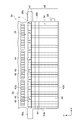
- FIG. 3 is a plan view showing a lattice base material according to an embodiment.
- FIG. 4 is an enlarged plan view showing the vicinity of the boundary between the first portion and the second portion of the second lattice bone in FIG.
- FIG. 5 is a plan view of the lattice base material including unnecessary portions.
- FIG. 6 is an enlarged plan view showing the vicinity of the boundary between the first portion and the second portion of the second lattice bone according to the first modification.
- FIG. 1 is a perspective view showing a storage battery according to an embodiment with a part thereof broken away.
- FIG. 2 is a plan view showing a positive electrode (negative electrode) according to one embodiment.
- FIG. 3 is a plan view showing a lattice base material according to an embodiment.
- FIG. 4 is an enlarged
- FIG. 7 is an enlarged plan view showing the vicinity of the boundary between the first part and the second part of the second lattice bone according to the second modification.
- FIG. 8 is an enlarged plan view showing the vicinity of a boundary portion between the first portion and the second portion of the second lattice bone according to the modified example 3.
- the lead storage battery 1 is, for example, a control valve type lead storage battery.
- the lead storage battery 1 includes an electrode group 3 and a case 5 that houses the electrode group 3.
- the electrode group 3 includes a plurality of positive electrodes 10, a plurality of negative electrodes 12, and a plurality of separators 13.
- the separator 13 is interposed between the positive electrode 10 and the negative electrode 12, and the positive electrode 10 and the negative electrode 12 are arranged alternately.
- the negative electrode 12 is arranged at the end of the positive electrode 10, the negative electrode 12, and the separator 13 in the arrangement direction (hereinafter, also simply referred to as “arrangement direction”).
- the positive electrode 10 has a positive electrode grid 10a.
- the positive electrode grid body 10a has a positive electrode current collector tab 10b.
- a positive electrode material 10c is provided on the positive electrode grid 10a.
- the positive electrode material 10c may include a positive electrode active material and an additive.
- the positive electrode active material is, for example, lead powder or the like.
- Examples of the additive include a carbon material, reinforcing short fibers and the like.
- the positive electrode grid body 10a is provided with convex portions 10d and 10e. The convex portions 10d and 10e are arranged at a predetermined interval and project outward from the positive electrode grid 10a.
- the negative electrode 12 has a negative electrode grid 12a.
- the negative electrode grid body 12a has a negative electrode current collecting tab 12b.
- a negative electrode material 12c is provided on the negative electrode grid 12a.
- the negative electrode material may include a negative electrode active material and an additive.
- the negative electrode active material is, for example, spongy lead. Examples of the additive include barium sulfate, a carbon material, and reinforcing short fibers.
- the negative electrode grid 12a is provided with projections 12d and 12e. The convex portions 12d and 12e are arranged at a predetermined interval and project outward from the negative electrode grid 12a.
- the separator 13 electronically insulates between the positive electrode 10 and the negative electrode 12 while allowing ions to pass therethrough, and has resistance to oxidizing property on the positive electrode 10 side and reducing property on the negative electrode 12 side.
- the material (material) of the separator 13 include glass fiber, resin, and inorganic material.
- Each of the positive electrodes 10 is electrically connected to the positive electrode terminal 14. Each positive electrode 10 and positive electrode terminal 14 are electrically connected by a positive electrode strap 17. Each of the negative electrodes 12 is electrically connected to the negative electrode terminal 16. Each negative electrode 12 and the negative electrode terminal 16 are electrically connected by a negative electrode strap 18.
- the case 5 has a main body 20 and a lid 22.
- the main body 20 is a box-shaped battery case.
- the main body 20 is made of a material such as polypropylene.
- the main body 20 is composed of four side surface portions 20a and a bottom portion (not shown).
- the lid 22 covers the opening of the main body 20.
- the lid 22 is provided with a first terminal portion 24 where the positive electrode terminal 14 is arranged, a second terminal portion 26 where the negative electrode terminal 16 is arranged, and a control valve 28.
- the grid body base material 30 forming the positive electrode grid body 10a and the negative electrode grid body 12a will be described.
- the positive electrode grid body 10a and the negative electrode grid body 12a are manufactured by processing the grid body base material 30.
- the lattice base material 30 includes a frame portion 32, a lattice portion 34, and protruding portions 36a and 36b.
- the directions (X direction, Y direction) defined in FIG. 3 are used for description.
- the X direction (first direction), the Y direction (second direction), and the Z direction are orthogonal (cross) to each other.
- the frame 32 defines an internal space for holding the electrode material (the positive electrode material 10c and the negative electrode material 12c shown in FIG. 2).
- the frame portion 32 is a rectangular frame. It has a pair of first frame bones 40a and 40b and a pair of second frame bones 42a and 42b. In the present embodiment, each of the pair of first frame bones 40a, 40b is shorter than each of the pair of second frame bones 42a, 42b.
- Each of the pair of first frame bones 40a, 40b faces each other in the X direction.
- Each of the pair of first frame bones 40a and 40b extends along the Y direction.
- Each of the pair of first frame bones 40a and 40b has a hexagonal prism shape. That is, the cross-sectional shape of the first frame bones 40a and 40b that intersects the Y direction is hexagonal.
- the first frame bone 40a and the first frame bone 40b may have the same thickness (cross-sectional area along the Y direction) or may have different thicknesses.
- Each of the pair of second frame bones 42a and 42b faces each other in the Y direction.
- Each of the pair of second frame bones 42a and 42b extends along the X direction.
- Each of the pair of second frame bones 42a and 42b has a hexagonal prism shape. That is, the cross-sectional shape of the second frame bones 42a and 42b that intersects the X direction is hexagonal.
- the second frame bone 42a is thicker than the second frame bone 42b.
- the first frame bones 40a, 40b and the second frame bones 42a, 42b are connected to each other at their ends.
- the protrusions 36a and 36b are provided on the pair of first frame bones 40a and 40b of the frame 32, respectively.
- the protrusions 36a and 36b are arranged so as to face each other in the X direction.
- the protruding portion 36a is provided on the first frame bone 40a.
- the protruding portion 36a is arranged on one end side in the extending direction of the first frame bone 40a. That is, the protruding portion 36a is arranged closer to the second frame bone 42a side of the frame portion 32 than the central portion in the extending direction of the first frame bone 40a.
- the projecting portion 36a projects outward from the first frame bone 40a along the X direction.
- the protruding portion 36b is provided on the first frame bone 40b.
- the protruding portion 36b is arranged on one end side in the extending direction of the first frame bone 40b. That is, the projecting portion 36b is arranged closer to the second frame bone 42a of the frame portion 32 than the central portion in the extending direction of the first frame bone 40a. The projecting portion 36b projects outward from the first frame bone 40b along the X direction.
- the protrusion 36b constitutes the protrusion 10e of the positive electrode 10 or the protrusion 12e of the negative electrode 12 (see FIG. 2).
- the lattice part 34 is provided in the frame part 32 and holds the electrode material (the positive electrode material 10c and the negative electrode material 12c shown in FIG. 2).
- the lattice part 34 has a plurality of first lattice bones 44 and a plurality of second lattice bones 45.
- Each of the plurality of first lattice bones 44 extends along the X direction. That is, one end of the first lattice bone 44 is connected to the first frame bone 40a, and the other end of the first lattice bone 44 is connected to the first frame bone 40b.
- the plurality of first lattice bones 44 are arranged at predetermined intervals in the Y direction.
- Each of the plurality of first lattice bones 44 has a hexagonal prism shape. That is, the cross-sectional shape of the first lattice bones 44 that intersects each X direction is hexagonal.
- Each of the plurality of second lattice bones 45 extends along the Y direction. That is, one end of the second lattice bone 45 is connected to the second frame bone 42a, and the other end of the second lattice bone 45 is connected to the second frame bone 42b.
- the plurality of second lattice bones 45 are arranged at predetermined intervals in the X direction.
- Each of the plurality of second lattice bones 45 has a hexagonal prism shape. That is, the cross-sectional shape of the second lattice bone 45 that intersects each Y direction is hexagonal.
- the first lattice bones 44 and the second lattice bones 45 may have the same thickness or different thicknesses.
- the second lattice bone 45 includes a first portion 47 extending from one of the second frame bones 42a to a predetermined position in the Y direction and another second frame bone 42b from the predetermined position (see FIG. 3). And a second portion 48 extending to. Thereafter, the predetermined position between the second frame bone 42a on one side and the second frame frame 42b on the other side (see FIG. 3) in the second lattice bone 45 is set at the boundary portion 49 between the first portion 47 and the second portion 48. As described below.
- the length ratio of the first portion 47 and the second portion 48 in the extending direction of the second lattice 45 is 1:7 to 1:13.
- the second lattice bone 45 is formed such that the average cross-sectional area A1 in the first portion 47 is larger than the average cross-sectional area A2 in the second portion 48. That is, the cross-sectional area CA1 of the second lattice bone 45 changes in the extending direction.
- the boundary 49 is formed in a region between the pair of protrusions 36a and 36b. Further, in the present embodiment, the boundary portion 49 is formed at the intersection with the first lattice bone 44.
- the average cross-sectional areas A1 and A2 of the second lattice bone 42 are known methods (for example, a method of measuring using Archimedes' principle, a laser volume meter or an acoustic volume). It is calculated by dividing the volume of the target site measured by a method using a meter, etc.) by the length in the longitudinal direction (Y-axis direction).
- the first portion 47 of the second lattice bone 45 is formed so that the cross-sectional area CA1 gradually increases from the boundary portion 49 toward the one second frame bone 42a.
- the second portion 48 of the second lattice bone 45 has a constant cross-sectional area CA2 in the extending direction.
- the thickest portion 45a of the second lattice bone 45 having the largest cross-sectional area CA1 is formed at the connecting portion of the first portion 47 to the second frame bone 42a.
- the cross-sectional area CA1 of the thickest part 45a of the first portion 47 is formed to be 1.4 to 2.0 times the cross-sectional area CA2 of the second portion 48.
- the frame portion 32 is provided with a convex portion 50.
- the convex portion 50 is provided on the first frame bone 40b.
- the convex portion 50 is arranged on the other end side in the extending direction of the first frame bone 40b.
- the convex portion 50 is arranged in the Y direction with a predetermined distance from the protruding portion 36b.
- the convex portion 50 projects outward from the first frame bone 40b along the X direction.
- the convex portion 50 constitutes the convex portion 10d of the positive electrode 10 and the convex portion 12d of the negative electrode 12.
- the manufacturing method of the lead storage battery 1 includes an electrode manufacturing process and an assembly process.
- the electrode manufacturing process is a process of obtaining electrodes (the positive electrode 10 and the negative electrode 12 shown in FIG. 2), and includes, for example, a preparation process, a filling process, a pressing process, a carrying process, an aging process, a drying process, and a cutting process. ..
- a preparation step of preparing the lattice base material 30 shown in FIG. 3 is performed.
- the number of grid base materials 30 to be prepared is determined according to the number of electrodes to be manufactured.
- the lattice base material 30 is produced by casting, for example.
- the lattice base material 30 is formed by pouring molten metal from one side of the molding die such as gravity casting.
- a pair of molding dies for the lattice base material 30 corresponding to the above-described shape are prepared.
- the sprue into which the molten lead is poured is formed outside the second frame bone 42a.
- the molding die is arranged such that the portion corresponding to the second frame bone 42b is below the portion corresponding to the second frame bone 42a.
- Molten lead is poured from the gate of the molding die arranged in this manner.
- One of the molding dies is removed when a predetermined time has elapsed after the molten lead was supplied to the molding dies.
- the lattice base material 30 is formed by releasing the molding die. As shown in FIG. 5, in the lattice base material 30 thus formed, an unnecessary portion 60 such as a burr is formed outside the second frame bone 42a corresponding to the gate side. These unnecessary portions 60 are cut by, for example, shirring processing in accordance with the outer shape of the second frame bone 42a (broken line C shown in FIG. 5).
- a filling step of filling an electrode material (active material) paste (not shown) into the lattice base material 30 shown in FIG. 3 is performed.
- the electrode material paste is filled by the filling machine (not shown) into the grid body base material 30 horizontally placed on the conveyor device (not shown).
- the filled grid body base material 30 that has been filled with the electrode material paste is subsequently conveyed by the conveyor device.
- the conveyor device is provided with a piano wire for peeling off the filled lattice base material 30 attached to the conveyor belt. The piano wire is stretched across the conveying direction of the conveyor device.
- a pressing step of pressing the electrode material paste filled in the grid base material 30 is performed.
- pressure is applied to the electrode material paste by sandwiching the lattice base material 30 in the vertical direction with a press roll (not shown).
- the electrode material paste is filled in the grid portion 34 of the grid body base material 30 from the filling side where the electrode material paste is filled to the side opposite to the filling side, and the filling property of the electrode material paste is improved. Further, the thickness of the electrode material paste filled in the grid body base material 30 is made uniform, and the electrode material paste is physically adhered to the grid portion 34.
- the grid base material 30 filled with the electrode material paste is transported.
- the lattice base material 30 is supported and conveyed by a pair of conveyor belts (not shown). Specifically, the protrusions 36a and 36b of the lattice base material 30 are supported by the pair of conveyor belts.
- the lattice base material 30 shifts from the horizontal state to the suspended state with respect to the conveyor belt, and is then transported in the suspended state.
- an aging step of aging the grid body base material 30 filled with the electrode material paste and a drying step of drying the grid body base material 30 filled with the electrode material paste are performed.
- the lattice base material 30 is aged and dried in a suspended state in which the pair of protrusions 36a and 36b are supported by a support member (not shown).
- a cutting process for cutting the lattice base material 30 is performed.
- the protrusion 36b of the grid body base material 30 is cut to form the protrusions 10e and 12e (see FIG. 2).
- an unformed electrode in which the positive electrode grid 10a or the negative electrode grid 12a is filled with the electrode material paste is obtained.
- a rotary cutter for example, is used to cut the lattice base material 30.
- polishing may be performed to remove the electrode material paste deposited on the frame 32.
- the assembly process of assembling the components including the electrode plate to obtain the lead storage battery 1 shown in FIG. 1 is performed.
- unformed positive electrodes and unformed negative electrodes are alternately laminated with the separators 13 interposed therebetween, and the positive electrode current collector tabs 10b of the positive electrode grid body 10a are connected (welded) together by the positive electrode straps 17 and the negative electrode grids are formed.
- the electrode group 3 is obtained by connecting (welding) the negative electrode current collecting tabs 12b of the body 12a to each other with the negative electrode strap 18. Then, by accommodating the electrode group 3 in the main body 20 of the case 5, an unformed battery is manufactured.
- a direct current is passed to perform battery case formation, the specific gravity of the formed electrolytic solution is adjusted to an appropriate specific gravity, and the lead storage battery 1 is obtained.
- the average cross-sectional area A1 of the first portion 47 of the second lattice bone 45 forming the lattice base material 30 is , And is formed to be larger than the average cross-sectional area A2 of the second portion 48. That is, the second lattice bone 45 is formed such that the cross-sectional area CA of the second lattice bone 45 changes so that the average cross-sectional area A on the one second frame bone 42a side increases along the extending direction. ing.
- the load resistance of the first portion 47 against a shear load is superior to the load resistance of the second portion 48 against a shear load.
- the first portion 47 of the second lattice bone 45 is formed such that the cross-sectional area CA1 gradually increases from the boundary portion 49 toward the one second frame bone 42a. There is. As a result, the deformation of the second lattice bones 45 during processing can be reduced more easily and efficiently.
- the thickest portion 45a having the maximum cross-sectional area CA1 in the second lattice bone 45 is formed in the first portion 47.
- the boundary portion 49 is formed in the region between the pair of protrusions 36a and 36b (see FIG. 3). Accordingly, the first portion 47 and the second portion 48 of the second lattice bone 45 can be set appropriately.
- the boundary portion 49 is formed at the intersection with the first lattice bone 44, the boundary portion 49 between the first portion 47 and the second portion 48 is easily formed. can do. In other words, it is possible to facilitate the formation of the casting die for the grid body base material 30.
- the first portion 47 of the second lattice bone 45 is formed such that the cross-sectional area CA1 gradually increases from the boundary portion 49 toward the one second frame bone 42a.
- the present invention is not limited to this.
- CA11 may be formed to be larger than the cross-sectional area CA12 of the second portion 48.
- the second lattice bone 45 may be formed such that the cross-sectional area CA becomes large on the way from the other second frame bone 42b to the one second frame bone 42a. Also in this case, similarly to the above-described embodiment, the load resistance of the first portion 147 against the shear load is superior to the load resistance of the second portion 48 against the shear load. As a result, it is possible to reduce the deformation of the lattice bone that occurs when cutting the unnecessary portion 60 formed outside the frame portion 32.
- the load resistance of the first portion 247 against the shear load is superior to the load resistance of the second portion 48 against the shear load. As a result, it is possible to reduce the deformation of the lattice bone that occurs when cutting the unnecessary portion 60 formed outside the frame portion 32.
- the boundary 49 is described as an example formed at the intersection with the first lattice bone 44, but the invention is not limited to this.
- the boundary portion 49 may be formed in a part of the second lattice bone 45 that does not intersect the first lattice bone 44.
- the load bearing capacity of the first portion 347 on the side closer to the second frame bone 42a against the shearing load is higher than the load bearing capacity of the second portion 348 against the shearing load.
- the pair of first frame bones 40a and 40b is shorter than the pair of second frame bones 42a and 42b, respectively. did.
- each of the pair of first frame bones 40a and 40b may be longer than each of the pair of second frame bones 42a and 42b, or may have the same length.
- first frame bones 40a, 40b and the second frame bones 42a, 42b of the frame portion 32, and the first lattice bones 44 and the second lattice bones 45 of the lattice portion 34 are hexagonal columns.
- first frame bones 40a and 40b and the second frame bones 42a and 42b of the frame portion 32, and the first lattice bones 44 and the second lattice bones 45 of the lattice portion 34 have other shapes (columns, polygonal columns, etc.). ).
- the boundary portion 49 has been described as an example formed in the region between the pair of protrusions 36a and 36b, but outside the region between the pair of protrusions 36a and 36b. It may be formed.
- SYMBOLS 1 Lead storage battery, 10... Positive electrode, 10a... Positive electrode grid, 12... Negative electrode, 12a... Negative grid, 30... Lattice body base material, 32... Frame part, 34... Lattice part, 36a... Projection part, 36b... Projection Part, 40a... First frame (one first frame), 40b... First frame (other first frame), 42a... Second frame (one second frame), 42b... Two frame bones (the other second frame bone), 44... First lattice bones, 45... Second lattice bones, 45a, 245a... Largest part, 47, 147, 247... First part, 48... Second part, 49 ... Boundary part, 50... Convex part, 60... Unnecessary part.
Landscapes
- Chemical & Material Sciences (AREA)
- Chemical Kinetics & Catalysis (AREA)
- Electrochemistry (AREA)
- General Chemical & Material Sciences (AREA)
- Cell Electrode Carriers And Collectors (AREA)
- Secondary Cells (AREA)
Abstract
Description
図1に示されるように、鉛蓄電池1は、例えば、制御弁式鉛蓄電池である。鉛蓄電池1は、電極群3と、電極群3を収容するケース5と、を備えている。 [Lead storage battery]
As shown in FIG. 1, the lead storage battery 1 is, for example, a control valve type lead storage battery. The lead storage battery 1 includes an
続いて、正極格子体10a及び負極格子体12aを構成する格子体基材30について説明する。正極格子体10a及び負極格子体12aは、格子体基材30を加工することにより製造される。図3に示されるように、格子体基材30は、枠部32と、格子部34と、突出部36a,36bと、を備えている。以下の説明においては、図3で規定する方向(X方向、Y方向)を説明に用いる。X方向(第一方向)、Y方向(第二方向)、及びZ方向は、互いに直交(交差)する。 [Lattice base material]
Next, the grid
次に、鉛蓄電池1の製造方法について説明する。鉛蓄電池1の製造方法は、電極製造工程と、組立工程と、を備えている。電極製造工程は、電極(図2に示される正極10及び負極12)を得る工程であって、例えば、準備工程、充填工程、プレス工程、搬送工程、熟成工程、乾燥工程、及び切断工程を含む。 [Lead storage battery manufacturing method]
Next, a method of manufacturing the lead storage battery 1 will be described. The manufacturing method of the lead storage battery 1 includes an electrode manufacturing process and an assembly process. The electrode manufacturing process is a process of obtaining electrodes (the
上記実施形態では、図4に示されるように、第二格子骨45の第一部分47は、境界部49から一方の第二枠骨42aに向かって断面積CA1が徐々に大きくなるように形成されている例を挙げて説明したが、これに限定されない。例えば、図6に示されるように、第一部分147全体の断面積CA11が等しく、かつ第二部分148全体の断面積CA12が等しくなるように形成されているという前提において、第一部分147の断面積CA11は第二部分48の断面積CA12よりも大きくなるように形成されてもよい。すなわち、第二格子骨45は、他方の第二枠骨42bから一方の第二枠骨42aに向かう途中で断面積CAが大きくなるように形成されてもよい。この場合も、上記実施形態と同様に、第一部分147のせん断荷重に対する耐荷重性が、第二部分48のせん断荷重に対する耐荷重性と比べて優れている。この結果、枠部32の外側に形成される不要部分60を切断する際に発生する格子骨の変形を低減できる。 (Modification 1)
In the above embodiment, as shown in FIG. 4, the
上記実施形態では、図4に示されるように第二格子骨45の最太部45aが一方の第二枠骨42aに接続される部分に形成される例を挙げて説明したが、これに限定されない。例えば、第一部分247における平均断面積A11が、第二部分48における平均断面積A12よりも大きくなるように形成されているという前提において、図7に示されるように、最太部245aは、第一部分247のどの部分に形成されてもよい。例えば、最太部245aは、第二格子骨45の延在方向において第一部分247の中心部近傍に設けられてもよい。この場合も、上記実施形態と同様に、第一部分247のせん断荷重に対する耐荷重性が、第二部分48のせん断荷重に対する耐荷重性と比べて優れている。この結果、枠部32の外側に形成される不要部分60を切断する際に発生する格子骨の変形を低減できる。 (Modification 2)
In the above embodiment, as shown in FIG. 4, an example in which the
上記実施形態及び変形例では、境界部49が第一格子骨44との交差部に形成されている例を挙げて説明したが、これに限定されない。例えば、図8に示されるように、境界部49は、第一格子骨44と交差しない第二格子骨45の一部に形成されていてもよい。この場合も、第二格子骨45の延在方向において、第二枠骨42aに近い側の第一部分347のせん断荷重に対する耐荷重性が、第二部分348のせん断荷重に対する耐荷重性と比べて優れている。この結果、枠部32の外側に形成される不要部分60を切断する際に発生する格子骨の変形を低減できる。 (Modification 3)
In the above-described embodiment and modification, the
上記実施形態では、図3に示されるように、枠部32において、一対の第一枠骨40a,40bのそれぞれが、一対の第二枠骨42a,42bのそれぞれよりも短い形態を一例に説明した。しかし、一対の第一枠骨40a,40bのそれぞれは、一対の第二枠骨42a,42bのそれぞれよりも長くてもよいし、長さが同等であってもよい。 (Other modifications)
In the above-described embodiment, as shown in FIG. 3, in the
Claims (10)
- 第一方向に対向して配置される一対の第一枠骨と、前記第一方向と交差する第二方向に対向して配置される一対の第二枠骨と、を有している枠部と、
前記枠部の内側に配置されており、一方の前記第一枠骨から他方の前記第一枠骨にまで延在すると共に、前記第二方向に沿って配列されている第一格子骨と、
前記枠部の内側に配置されており、一方の前記第二枠骨から他方の前記第二枠骨にまで延在すると共に、前記第一方向に沿って配列されている第二格子骨と、を備え、
前記第二格子骨は、一方の前記第二枠骨から前記第二方向に所定位置にまで延びる第一部分と前記所定位置から他方の前記第二枠骨にまで延びる第二部分とからなり、
前記第二格子骨は、前記第一部分における断面積が、前記第二部分における断面積よりも大きくなるように形成されている、格子体基材。 A frame portion having a pair of first frame bones arranged to face each other in a first direction and a pair of second frame bones arranged to face each other in a second direction intersecting the first direction. When,
It is arranged inside the frame portion, and extends from one of the first frame bones to the other of the first frame bones, and a first lattice bone arranged along the second direction,
The second lattice bones, which are arranged inside the frame portion, extend from one of the second frame bones to the other of the second frame bones, and are arranged along the first direction, Equipped with
The second lattice bone is composed of a first portion extending from one of the second frame bones to a predetermined position in the second direction and a second portion extending from the predetermined position to the other second frame bone,
The said 2nd lattice bone is a lattice body base material formed so that the cross-sectional area in the said 1st part may become larger than the cross-sectional area in the said 2nd part. - 第一方向に対向して配置される一対の第一枠骨と、前記第一方向と交差する第二方向に対向して配置される一対の第二枠骨と、を有している枠部と、
前記枠部の内側に配置されており、一方の前記第一枠骨から他方の前記第一枠骨にまで延在すると共に、前記第二方向に沿って配列されている第一格子骨と、
前記枠部の内側に配置されており、一方の前記第二枠骨から他方の前記第二枠骨にまで延在すると共に、前記第一方向に沿って配列されている第二格子骨と、を備え、
前記第二格子骨は、一方の前記第二枠骨から前記第二方向に所定位置にまで延びる第一部分と前記所定位置から他方の前記第二枠骨にまで延びる第二部分とからなり、
前記第二格子骨は、前記第一部分における平均断面積が、前記第二部分における平均断面積よりも大きくなるように形成されている、格子体基材。 A frame portion having a pair of first frame bones arranged to face each other in a first direction and a pair of second frame bones arranged to face each other in a second direction intersecting the first direction. When,
It is arranged inside the frame portion, and extends from one of the first frame bones to the other of the first frame bones, and a first lattice bone arranged along the second direction,
The second lattice bones, which are arranged inside the frame portion, extend from one of the second frame bones to the other of the second frame bones, and are arranged along the first direction, Equipped with
The second lattice bone is composed of a first portion extending from one of the second frame bones to a predetermined position in the second direction and a second portion extending from the predetermined position to the other second frame bone,
The said 2nd lattice bone is a lattice base material formed so that the average cross-sectional area in the said 1st part may become larger than the average cross-sectional area in the said 2nd part. - 前記第二格子骨において断面積が最大となる最太部は、前記第一部分に形成されている、請求項2記載の格子体基材。 The lattice base material according to claim 2, wherein the thickest portion having the largest cross-sectional area in the second lattice bone is formed in the first portion.
- 前記第二格子骨の前記第一部分は、前記所定位置から一方の前記第二枠骨に向かって断面積が徐々に大きくなるように形成されている、請求項1~3の何れか一項記載の格子体基材。 4. The first portion of the second lattice bone is formed so that the cross-sectional area gradually increases from the predetermined position toward one of the second frame bones. Lattice base material.
- 前記第一枠骨には、前記第一格子骨が延在する方向に前記枠部の外側に突出するように設けられると共に、前記第一格子骨が延在する方向に互いに対向するように設けられる一対の突出部が形成されている、請求項1~4の何れか一項記載の格子体基材。 The first frame bone is provided so as to project to the outside of the frame portion in the direction in which the first lattice bone extends, and is provided so as to face each other in the direction in which the first lattice bone extends. The lattice base material according to any one of claims 1 to 4, wherein a pair of protrusions are formed.
- 前記所定位置は、前記一対の突出部の間の領域に位置している、請求項5記載の格子体基材。 The lattice base material according to claim 5, wherein the predetermined position is located in a region between the pair of protrusions.
- 前記所定位置は、前記第一格子骨との交差部に位置している、請求項1~6の何れか一項記載の格子体基材。 The lattice base material according to any one of claims 1 to 6, wherein the predetermined position is located at an intersection with the first lattice bone.
- 前記所定位置は、一方の前記第二枠骨に隣接する前記第一格子骨との交差部に位置している、請求項7記載の格子体基材。 The lattice base material according to claim 7, wherein the predetermined position is located at an intersection with the first lattice bone adjacent to one of the second frame bones.
- 請求項1~8の何れか一項記載の格子体基材から形成される格子体と、
前記格子体に保持されている電極材と、を備える、電極。 A lattice body formed from the lattice body substrate according to any one of claims 1 to 8,
An electrode material held by the grid body. - 請求項1~8の何れか一項記載の格子体基材から形成される格子体と、前記格子体に保持されている正極材とを有する正極と、
前記格子体と、前記格子体に保持されている負極材とを有する負極と、
前記正極と前記負極との間に配置されたセパレータと、を備える、鉛蓄電池。 A positive electrode comprising a grid body formed from the grid body substrate according to any one of claims 1 to 8, and a positive electrode material held by the grid body.
A negative electrode having the lattice body and a negative electrode material held by the lattice body;
A lead storage battery, comprising: a separator disposed between the positive electrode and the negative electrode.
Priority Applications (2)
| Application Number | Priority Date | Filing Date | Title |
|---|---|---|---|
| CN202080012105.2A CN113366675A (en) | 2019-02-05 | 2020-01-20 | Grid base material, electrode and lead storage battery |
| JP2020571073A JPWO2020162152A1 (en) | 2019-02-05 | 2020-01-20 | Lattice substrate, electrodes and lead-acid battery |
Applications Claiming Priority (2)
| Application Number | Priority Date | Filing Date | Title |
|---|---|---|---|
| JP2019-019027 | 2019-02-05 | ||
| JP2019019027 | 2019-02-05 |
Publications (1)
| Publication Number | Publication Date |
|---|---|
| WO2020162152A1 true WO2020162152A1 (en) | 2020-08-13 |
Family
ID=71947420
Family Applications (1)
| Application Number | Title | Priority Date | Filing Date |
|---|---|---|---|
| PCT/JP2020/001757 WO2020162152A1 (en) | 2019-02-05 | 2020-01-20 | Lattice base material, electrode, and lead storage battery |
Country Status (4)
| Country | Link |
|---|---|
| JP (1) | JPWO2020162152A1 (en) |
| CN (1) | CN113366675A (en) |
| TW (1) | TW202040857A (en) |
| WO (1) | WO2020162152A1 (en) |
Citations (6)
| Publication number | Priority date | Publication date | Assignee | Title |
|---|---|---|---|---|
| JPS5882775U (en) * | 1981-11-30 | 1983-06-04 | 古河電池株式会社 | lead acid battery |
| JPS58216361A (en) * | 1982-06-10 | 1983-12-16 | Matsushita Electric Ind Co Ltd | Plate grid for lead storage battery |
| JPS5958757A (en) * | 1982-09-28 | 1984-04-04 | Furukawa Electric Co Ltd:The | Complex grid base plate for storage battery |
| CN103406521A (en) * | 2013-09-02 | 2013-11-27 | 漳州市华威电源科技有限公司 | Lead acid battery grid and processing mold thereof |
| JP2014535153A (en) * | 2011-11-03 | 2014-12-25 | ジョンソン コントロールズ テクノロジー カンパニーJohnson Controls Technology Company | Battery grid with altered corrosion resistance |
| JP2017069123A (en) * | 2015-10-01 | 2017-04-06 | 日立化成株式会社 | Punched lattice for lead acid battery, positive electrode for lead acid battery, and lead acid battery using the same |
-
2020
- 2020-01-20 WO PCT/JP2020/001757 patent/WO2020162152A1/en active Application Filing
- 2020-01-20 CN CN202080012105.2A patent/CN113366675A/en active Pending
- 2020-01-20 JP JP2020571073A patent/JPWO2020162152A1/en active Pending
- 2020-01-30 TW TW109102709A patent/TW202040857A/en unknown
Patent Citations (6)
| Publication number | Priority date | Publication date | Assignee | Title |
|---|---|---|---|---|
| JPS5882775U (en) * | 1981-11-30 | 1983-06-04 | 古河電池株式会社 | lead acid battery |
| JPS58216361A (en) * | 1982-06-10 | 1983-12-16 | Matsushita Electric Ind Co Ltd | Plate grid for lead storage battery |
| JPS5958757A (en) * | 1982-09-28 | 1984-04-04 | Furukawa Electric Co Ltd:The | Complex grid base plate for storage battery |
| JP2014535153A (en) * | 2011-11-03 | 2014-12-25 | ジョンソン コントロールズ テクノロジー カンパニーJohnson Controls Technology Company | Battery grid with altered corrosion resistance |
| CN103406521A (en) * | 2013-09-02 | 2013-11-27 | 漳州市华威电源科技有限公司 | Lead acid battery grid and processing mold thereof |
| JP2017069123A (en) * | 2015-10-01 | 2017-04-06 | 日立化成株式会社 | Punched lattice for lead acid battery, positive electrode for lead acid battery, and lead acid battery using the same |
Also Published As
| Publication number | Publication date |
|---|---|
| JPWO2020162152A1 (en) | 2021-12-09 |
| TW202040857A (en) | 2020-11-01 |
| CN113366675A (en) | 2021-09-07 |
Similar Documents
| Publication | Publication Date | Title |
|---|---|---|
| JP2022093710A (en) | Battery grid with varied corrosion resistance | |
| JP4892651B1 (en) | Lead acid battery | |
| US6385829B2 (en) | Manufacturing method for a lead-acid battery electrode plate | |
| WO2020162152A1 (en) | Lattice base material, electrode, and lead storage battery | |
| EP2174367A2 (en) | An electrode plate | |
| US20220158279A1 (en) | Battery and method of manufacturing same | |
| WO2022233050A1 (en) | Electrode assembly, battery, device, and manufacturing method for electrode assembly | |
| JPH08287905A (en) | Plate for lead-acid battery and its manufacture | |
| US4422494A (en) | Vibratory forming of shaped lead joints | |
| WO2020148836A1 (en) | Lattice body substrate, electrode, and lead storage cell | |
| WO2020129998A1 (en) | Secondary battery electrode plate and secondary battery using same | |
| EP3145006B1 (en) | Battery grid and method of making | |
| JPS6110866A (en) | Sealed lead storage battery | |
| EP1830429B1 (en) | lead acid accumulator | |
| JP2014197456A (en) | Method of positive electrode grid body for lead-acid storage battery and lead-acid storage battery | |
| JPS60115152A (en) | Separator for lead storage battery | |
| JP2019186028A (en) | Grid and lead-acid battery | |
| WO2020003729A1 (en) | Grid body, lead-acid battery, and manufacturing method for lead-acid battery | |
| JPH07326359A (en) | Electrode plate for lead-acid battery | |
| JPH11135131A (en) | Lead-acid battery | |
| JP2000215898A (en) | Lead-acid battery grid body | |
| JP4822583B2 (en) | Method for manufacturing a lead-acid battery plate | |
| JPS59114763A (en) | Manufacture of lead-acid battery | |
| JPH0753253Y2 (en) | Multi-piece electrode plate assembly for lead-acid battery | |
| JPH0548364Y2 (en) |
Legal Events
| Date | Code | Title | Description |
|---|---|---|---|
| 121 | Ep: the epo has been informed by wipo that ep was designated in this application |
Ref document number: 20752277 Country of ref document: EP Kind code of ref document: A1 |
|
| ENP | Entry into the national phase |
Ref document number: 2020571073 Country of ref document: JP Kind code of ref document: A |
|
| NENP | Non-entry into the national phase |
Ref country code: DE |
|
| 32PN | Ep: public notification in the ep bulletin as address of the adressee cannot be established |
Free format text: NOTING OF LOSS OF RIGHTS PURSUANT TO RULE 112(1) EPC (EPO FORM 1205A DATED 02/11/2021) |
|
| 122 | Ep: pct application non-entry in european phase |
Ref document number: 20752277 Country of ref document: EP Kind code of ref document: A1 |