WO2020162048A1 - 信号変換システム、機械学習システムおよび信号変換プログラム - Google Patents
信号変換システム、機械学習システムおよび信号変換プログラム Download PDFInfo
- Publication number
- WO2020162048A1 WO2020162048A1 PCT/JP2019/049337 JP2019049337W WO2020162048A1 WO 2020162048 A1 WO2020162048 A1 WO 2020162048A1 JP 2019049337 W JP2019049337 W JP 2019049337W WO 2020162048 A1 WO2020162048 A1 WO 2020162048A1
- Authority
- WO
- WIPO (PCT)
- Prior art keywords
- signal
- time
- data
- values
- machine learning
- Prior art date
- Legal status (The legal status is an assumption and is not a legal conclusion. Google has not performed a legal analysis and makes no representation as to the accuracy of the status listed.)
- Ceased
Links
Images
Classifications
-
- G—PHYSICS
- G10—MUSICAL INSTRUMENTS; ACOUSTICS
- G10L—SPEECH ANALYSIS TECHNIQUES OR SPEECH SYNTHESIS; SPEECH RECOGNITION; SPEECH OR VOICE PROCESSING TECHNIQUES; SPEECH OR AUDIO CODING OR DECODING
- G10L25/00—Speech or voice analysis techniques not restricted to a single one of groups G10L15/00 - G10L21/00
- G10L25/27—Speech or voice analysis techniques not restricted to a single one of groups G10L15/00 - G10L21/00 characterised by the analysis technique
- G10L25/30—Speech or voice analysis techniques not restricted to a single one of groups G10L15/00 - G10L21/00 characterised by the analysis technique using neural networks
-
- G—PHYSICS
- G10—MUSICAL INSTRUMENTS; ACOUSTICS
- G10L—SPEECH ANALYSIS TECHNIQUES OR SPEECH SYNTHESIS; SPEECH RECOGNITION; SPEECH OR VOICE PROCESSING TECHNIQUES; SPEECH OR AUDIO CODING OR DECODING
- G10L25/00—Speech or voice analysis techniques not restricted to a single one of groups G10L15/00 - G10L21/00
- G10L25/48—Speech or voice analysis techniques not restricted to a single one of groups G10L15/00 - G10L21/00 specially adapted for particular use
- G10L25/51—Speech or voice analysis techniques not restricted to a single one of groups G10L15/00 - G10L21/00 specially adapted for particular use for comparison or discrimination
Definitions
- the present invention relates to a signal conversion system, a machine learning system, and a signal conversion program.
- Patent Document 1 discloses a technique of converting a numerical value indicating input information into a binary bit sequence. Specifically, a configuration is disclosed in which the numerical value of an ID indicating a word is converted into a binary bit sequence.
- the signal conversion system includes a signal acquisition unit that acquires a signal that is a time-varying signal and in which each of the values at a plurality of positions on the time axis is represented by one component, A conversion unit that converts each of the values for each of the plurality of positions into a multidimensional amount expressed by the values of the plurality of components, and the multidimensional amount is at least the value of the same component of the multidimensional amount at a plurality of consecutive positions.
- L is an integer that is 1 or more and is equal to or less than the number of components of a multidimensional quantity
- the conversion unit converts a signal in which the value of one position on the time axis is expressed by one component into a multidimensional amount expressed by the values of multiple components.
- the signal can be expressed in a format capable of capturing more various characteristics than the original signal.
- the output unit outputs the multidimensional amount as L pieces of time-series data including at least values of the same component of the multidimensional amount at a plurality of consecutive positions on the time axis. Further, by applying the L time-series data to a machine learning model, information regarding the characteristics of the signal is output.
- the time change of the values of the same component of the multidimensional amount is shown, and the feature of the time change of the signal can be grasped for each component.
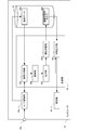
- FIG. 1 is a diagram showing a schematic configuration of a computer 10 that functions as a signal conversion system, a feature output system, and a machine learning system according to an embodiment of the present invention.
- the computer 10 includes a microphone 10a, an A/D conversion unit 10b, a control unit 20, a storage medium 30, and a display unit 40.
- the control unit 20 includes a CPU, a RAM, and a ROM (not shown), and can execute various programs stored in the storage medium 30 or the like.
- the microphone 10a, the A/D conversion unit 10b, the control unit 20, the storage medium 30, and the display unit 40 may be configured as an integrated computer, or at least a part of them may be different devices, such as a USB cable. It may be connected.
- the computer 10 may have various modes, for example, a stationary general-purpose computer or a portable computer such as a smartphone or a tablet terminal.
- the microphone 10a collects ambient sound and outputs an analog sound wave signal indicating a temporal change in sound pressure.
- the A/D conversion unit 10b is a device that converts an analog signal into a digital signal, and samples the analog sound wave signal at the sampling frequency instructed by the control unit 20 and outputs it as a digital sound wave signal.
- the digital sound wave signal is composed of sound pressure amplitude values at a plurality of positions on the time axis, and the amplitude values are represented by decimal numbers. Therefore, the digital sound wave signal is a signal in which each of the values at a plurality of positions on the time axis is represented by one component.
- the storage medium 30 is a medium capable of storing various kinds of information, and in the present embodiment, the teacher data 30a for machine learning is stored in the storage medium 30.
- the machine-learned model is generated by machine learning, information indicating the model is stored in the storage medium 30 as the machine-learned model 30b.
- the display unit 40 is a display that displays various types of information.
- control unit 20 can execute the signal conversion program.
- the signal conversion program is a program that causes the control unit 20 to execute the function of converting and outputting a time-varying signal. Further, in the present embodiment, the signal conversion program has a function of performing machine learning based on the converted signal, and a function of outputting a characteristic of sound based on the converted signal.
- the control unit 20 When the signal conversion program is executed, the control unit 20 functions as the signal acquisition unit 20a, the conversion unit 20b, the output unit 20c, the machine learning unit 20d, and the feature output unit 20e.
- the type of sound source is output as a feature of the sound source. That is, the control unit 20 can classify the types of sound sources. Although the number of classifications may be arbitrary, here, an example of classifying whether or not the sound source is music will be described.
- machine learning is used to classify the types of sound sources. That is, the machine-learned model 30b is generated in advance before the classification, and the classification result is output by inputting the digital signal indicating the sound to be classified into the machine-learned model 30b. In order to perform such classification accurately, it is preferable to use a digital signal capable of capturing detailed characteristics of sound as an input value to the machine-learned model 30b.
- the control unit 20 has a function of converting a digital sound wave signal indicating a sound into a multidimensional amount and outputting it as time series data capable of capturing detailed characteristics of the sound.
- An example of the time-series data is a data string surrounded by a dotted line in FIG. Details will be described later.
- the machine learning is performed using the time series data, and the sound is classified with high accuracy by performing the classification using the time series data. That is, in the present embodiment, time series data is used as input data when learning a machine learning target model, and time series data is also used as input data for performing classification based on the machine learned model 30b. Is used.
- the generation of the time series data is realized by the control unit 20 executing the functions of the signal acquisition unit 20a, the conversion unit 20b, and the output unit 20c. Further, the machine learning using the time series data is realized by the control unit 20 executing the function of the machine learning unit 20d. Furthermore, the classification of sound source types using time-series data is realized by the control unit 20 executing the function of the feature output unit 20e. In the following, machine learning and sound source type classification (feature output) will be described in order.
- the teacher data 30a is prepared in advance for machine learning.
- the teacher data 30a is information in which a sound wave signal is associated with a sound source type of a sound indicated by the sound wave signal. For example, a set of data in which a sound wave signal indicating music is associated with music, and a set of data in which a sound wave signal indicating a sound other than music (human utterances, etc.) is associated with not music
- the data can be the teacher data 30a.
- a sufficient amount of data for machine learning is prepared in advance.
- the teacher data 30a may be prepared by various methods, for example, data acquired by a plurality of clients may be collected by a server or the like.
- the computer 10 can also generate the teacher data 30a. That is, the sound is collected by the microphone 10a included in the computer 10, the information indicating the type of the sound source is associated with the digital sound wave signal converted by the A/D conversion unit 10b, and is stored as the teacher data 30a in the storage medium 30. May be remembered.
- the teacher data 30a the values indicating the sound pressures at a plurality of positions on the time axis are expressed in decimal numbers.
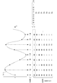
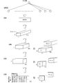
- FIG. 2 is a diagram for explaining data conversion.
- a part of the sound wave signal Ss is shown on the graph.
- the A/D conversion unit 10 b converts the sound wave signal into a digital sound wave signal at the sampling frequency instructed by the control unit 20.
- the black circles superimposed on the sound wave signal Ss indicate the sampled amplitude, and the sampling value is shown below it.
- the first sampling value is 0 in decimal and the second sampling value is 12 in decimal.
- information (label) indicating the type of sound source is associated with the set of values at a plurality of positions on the time axis thus obtained.
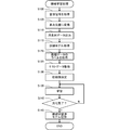
- the machine learning process is a process of optimizing a training model forming a neural network, and in the present embodiment, the machine learning process is executed according to the flowchart shown in FIG.
- the model is information indicating an equation for deriving the correspondence between the classification target data and the classification result data
- the classification result is whether or not music.
- the classification target is the time-series data converted and output from the sound wave signal. That is, in the present embodiment, when a digital sound wave signal (decimal number expression) that has been A/D converted by the A/D conversion unit 10b is not directly input to the model of machine learning, but is converted and output. Enter the series data.
- the control unit 20 includes a signal acquisition unit 20a, a conversion unit 20b, and an output unit 20c in order to perform processing using time-series data as described above.
- the signal acquisition unit 20a causes the control unit 20 to perform a function of acquiring a signal that is a time-varying signal and in which each of the values at a plurality of positions on the time axis is expressed by one component.
- the time-varying signal is a signal in which a sound wave signal is sampled at a predetermined sampling frequency and expressed as a decimal value, and in machine learning, the teacher data 30a corresponds to the signal.
- control unit 20 refers to the storage medium 30 and acquires a sound wave signal from each teacher data 30a (step S100).
- a plurality of data sets in which the amplitudes of the sound wave signal at a plurality of positions on the time axis are expressed in decimal are obtained.
- the conversion unit 20b is a program module that causes the control unit 20 to execute a function of converting each value at each of a plurality of positions into a multidimensional amount expressed by a plurality of component values. That is, since the expression of the amplitude by the decimal number indicates the magnitude of the amplitude at a certain position on the time axis by one component, the control unit 20 expresses the sound wave signal by a larger number of components, and thus the sound wave is generated. The signal is converted into a multidimensional quantity (step S105).
- the control unit 20 determines the magnitude of the amplitude at each position on the time axis. Is converted to a binary value. That is, each digit of the converted binary number becomes a multidimensional component.
- the converted binary value (8 bits) is shown below the value indicating the amplitude of the sound pressure.
- the lower digits to the upper digits are displayed so as to be arranged from the upper side to the lower side.
- the first sampled value of decimal 0 is binary number 00000000
- the second sampled value of decimal 12 is binary number 00001100.
- the time length of the actual digital sound wave signal is longer than the time length shown in FIG. 2, and for example, the digital sound wave signal is composed of 1 second of data (10000 pieces of data) sampled at 10 kHz.
- the digital sound wave signal is a conversion target.
- the output unit 20c is a program module that causes the control unit 20 to execute a function of outputting a multidimensional amount as time-series data including at least values of the same component of the multidimensional amount at a plurality of consecutive positions.
- the digit of the binary value converted in step S105 is regarded as a component, and the control unit 20 extracts the value of each digit by the function of the output unit 20c to obtain the time series data.
- Output step S110).
- the least significant digit of the multidimensional amount represented by a binary number is surrounded by a dashed line.
- the control unit 20 generates data in which the respective values existing at different positions on the time axis in the least significant digit are arranged in the order on the time axis as the time series data D 1 of the least significant digit component.
- the time-series data is one-dimensional data indicating the time change of the value of the same component.
- One-dimensional data may be implemented for multi-dimensional quantities of each component. That is, when the time series data is extracted for the upper digit of the binary number, the time series data shows a large change in the amplitude of the digital sound wave signal. On the other hand, when the time series data is extracted for the lower digit of the binary number, the time series data indicates a fine change in the amplitude of the digital sound wave signal.
- the number of components to be extracted as time-series data may be selected from an integer equal to or greater than 1 and equal to or less than the number of components of a multidimensional amount according to the purpose of machine learning or a classification target.
- time-series data is output for all 8-digit binary components (all digits). Therefore, FIG. 2 shows that the time series data D 2 to D 8 are output in addition to the time series data D 1 .
- the sound is classified based on the time series data output as described above. That is, a machine learning process for optimizing a model for inputting time series data by machine learning is performed.
- Machine learning may be performed by various methods, but in the present embodiment, machine learning is performed by a neural network including a convolutional neural network (CNN: Convolutional Neural Network) and a recurrent neural network (RNN: Recurrent Neural Network).
- CNN convolutional neural network
- RNN Recurrent Neural Network
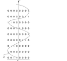
- FIG. 3 is a diagram showing an example of a model applicable to the example shown in FIG. In FIG. 3, the model is described so that the calculation proceeds from the lower part to the upper part.
- the initial three layers are composed of CNN.
- the output result by CNN is input to RNN, and the output by RNN reaches the output layer through full coupling.
- time-series data D 1 to D 8 for 8 channels which are input data are illustrated.
- digital sound wave signals obtained by sampling 10,000 positions on the time axis, that is, 10,000 times at 10 kHz are converted and output as time-series data.
- a calculation for convoluting the time-series data D 1 to D 8 in the time direction is performed.
- each of the time series data D 1 to D 8 is one-dimensional time series data and has a total of 8 channels. Therefore, in the present embodiment, a two-dimensional (time axis direction and channel direction) filter is prepared and the convolution operation is performed.
- the filter is two-dimensional, and is a filter that convolves 30 ⁇ 8 values (values of 30 consecutive positions on the time axis for 8 channels).
- the size of the filter is shown as 1 ⁇ 30 ⁇ 8.
- the size of the filter is not limited to 30, and may be, for example, 50, 40, 20 or 10, or may be in a range between any two of these exemplified numerical values. The shorter the filter size, the earlier the processing after signal acquisition can be started.
- the input data is eight channels, but it is not limited to eight.
- the number of filters is not limited, the number of filters in the first layer of CNN is 128 in the example shown in FIG. In FIG. 3, these filters are shown as F 1-1 to F 1-128 .
- a filter having a short size in the time axis direction can be used as described above, it is possible to capture a minute change in time series data as compared with the conventional technique.
- a filter having a short size in the time axis direction directly causes a minute amplitude change or a global amplitude time change. Is difficult to capture.
- the Fourier transform or the like if a short-term signal is used in the time space, the accuracy of the information in the frequency space will decrease. That is, more time is required from the acquisition of the signal to the output of the feature.
- Each filter is applied to each of the time series data D 1 to D 8 with a predetermined padding or stride. For example, if the stride 10 is appropriately padded, the 10,000 data will be 1,000. The output result of one filter is obtained by adding these. Therefore, when the number of filters is 128, 128 one-dimensional data having 1000 data are generated. In FIG. 3, the 1 ⁇ 1000 ⁇ 128 data is indicated by a rectangle. Of course, hyperparameters such as stride and padding are examples, and the number of output data (1000 pieces, etc.) is also an example (same for other layers).
- FIG. 3 shows an example in which 256 filters of size 1 ⁇ 30 ⁇ 128 are prepared in the second layer, and 512 filters of size 1 ⁇ 30 ⁇ 256 are further prepared in the third layer. ing. Stride and padding are similar to the first layer.
- 1 ⁇ 10 ⁇ 512 pieces of data D CNN are output by the above-described calculation of the three layers.
- the data D CNN becomes an input to the RNN.
- the element forming the RNN shown in FIG. 3 is an LSTM (Long Short-Term Memory)
- the element may be a GRU (Gated Recurrent Unit) or a bidirectional model may be adopted.
- a configuration can be adopted.
- the hyperparameter may be various parameters.
- the LSTM outputs 1024, and the data Y 1 to Y 1024 output from the last LSTM are input to the next layer. That is, the data Y 1 to Y 1024 are input to the fully connected layer, and the classification result indicating whether or not the layer is the music next to the fully connected layer is output.
- the control unit 20 executes the machine learning process based on the above model by the function of the machine learning unit 20d. That is, the control unit 20 machine-learns a machine-learned model that receives time-series data and outputs information related to the characteristics of the sound source of the signal by the function of the machine learning unit 20d. Specifically, the control unit 20 acquires the training model by the function of the machine learning unit 20d (step S115). That is, various kinds of information corresponding to the structure of the neural network as shown in FIG. 3 (information such as a filter indicating a model and an activation function) is defined in advance, and the control unit 20 acquires the information. Get the training model.
- the control unit 20 acquires the label of the teacher data 30a by the function of the machine learning unit 20d (step S120). That is, the control unit 20 acquires the label indicating the type of the sound source of each sound wave signal acquired in step S100. For example, in the example shown in FIG. 3, the label indicates whether the output value of the node in the output layer is 1, 0, and when the sound source of the sound wave signal acquired in step S100 is music. 1, 0 is acquired when it is a sound other than music.
- control unit 20 acquires test data by the function of the machine learning unit 20d (step S125).
- the control unit 20 extracts a part of the data acquired in step S110, and associates the label acquired in step S120 with it to make it test data.
- the test data is data for confirming whether or not learning generalization has been performed, and is not used for machine learning.
- control unit 20 determines the initial value by the function of the machine learning unit 20d (step S130). That is, the control unit 20 gives initial values to the variable parameters (filter weight, bias, etc.) to be learned in the training model acquired in step S115.
- the initial value may be determined by various methods. Of course, the initial values may be adjusted so that the parameters are optimized during the learning process, or the learned parameters may be acquired from various databases and used.
- control unit 20 performs learning by the function of the machine learning unit 20d (step S135). That is, the control unit 20 inputs the time-series data output in step S110 to the training model acquired in step S115, and outputs information indicating the classification result. When the information indicating the classification result is output, the control unit 20 specifies the error by the loss function indicating the error between the output and the label acquired in step S120. When the loss function is obtained, the control unit 20 updates the parameter by a predetermined optimization algorithm, for example, the stochastic gradient descent method. That is, the control unit 20 repeats the process of updating the parameter based on the differentiation of the loss function by the parameter for a predetermined number of times.
- a predetermined optimization algorithm for example, the stochastic gradient descent method. That is, the control unit 20 repeats the process of updating the parameter based on the differentiation of the loss function by the parameter for a predetermined number of times.
- the control unit 20 determines whether or not the generalization of the training model has been completed (step S140). That is, the control unit 20 inputs the test data acquired in step S125 into the training model and outputs the sound wave signal classification result. Then, the control unit 20 obtains the number of coincidences between the output classification result and the classification result associated with the test data (the number of errors between the classification result and the label is equal to or less than the default value), The classification accuracy is obtained by dividing by the number of samples. In the present embodiment, the control unit 20 determines that the generalization is completed when the classification accuracy is equal to or higher than the threshold value.
- the validity of hyperparameters may be verified. That is, in a configuration in which a hyperparameter that is a variable amount other than the variable parameter to be learned, such as the filter size and the number of nodes, is tuned, the control unit 20 determines the validity of the hyperparameter based on the verification data. You may verify.
- the verification data may be acquired by preliminarily extracting the verification data by the same process as in step S125 and securing it as data not used for training.
- step S140 If it is not determined in step S140 that the generalization of the training model is completed, the control unit 20 repeats step S135. That is, the process of further updating the variable parameter to be learned is performed. On the other hand, when it is determined in step S140 that the generalization of the training model is completed, the control unit 20 records the machine-learned model (step S145). That is, the control unit 20 records the training model in the storage medium 30 as the machine-learned model 30b.
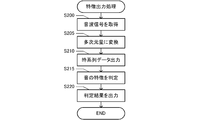
- the control unit 20 acquires a sound wave signal (step S200). That is, when a sound wave is output from the sound source, the microphone 10a acquires the sound wave and outputs an analog sound wave signal.
- the control unit 20 preliminarily instructs the A/D conversion unit 10b to have the same sampling frequency as that used for machine learning.
- the A/D converter 10b samples the analog sound wave signal at the sampling frequency and converts it into a digital sound wave signal.
- the control unit 20 acquires the digital sound wave signal by the function of the signal acquisition unit 20a. For example, in the case of the sound wave signal Ss shown in FIG. 2, since the A/D conversion unit 10b outputs a decimal sound wave signal (0, 12, 6,,... ), the control unit 20 controls the digital sound signal Ss. Acquire sound wave signals.
- the control unit 20 converts the sound wave signal into a multidimensional amount by the function of the A/D conversion unit 10b (step S205). That is, the control unit 20 acquires the digital sound wave signal acquired in step S200, and converts the decimal value indicating the amplitude of each of a plurality of positions on the time axis into a binary number. For example, in step S200, when the digital sound wave signals (0, 12, 6,,,) shown in FIG. 2 are acquired, the binary multidimensional quantity (000000000001100,,,) shown in FIG. 2 is obtained. To be acquired.
- control unit 20 outputs the time series data by the function of the output unit 20c (step S210). That is, the control unit 20 extracts a value for each digit of the multidimensional amount and generates time-series data of each digit. For example, in the example shown in FIG. 2, the control unit 20 acquires the time series data D 1 to D 8 .
- the control unit 20 determines the feature of the sound by the function of the feature output unit 20e (step S215). That is, the control unit 20 acquires the machine-learned model 30b and inputs the time-series data D 1 to D 8 output in step S210 to the machine-learned model 30b.
- the control unit 20 uses the parameters indicated by the machine-learned model 30b to calculate CNN, RNN, etc. shown in FIG. As a result, the value of the output layer is determined.
- the time-series data D 1 to D 8 which are eight- dimensional one-dimensional data are input to the machine-learned model 30b, but the number of channels is not limited to eight. It may be an integer greater than or equal to 1 and less than or equal to the number of multidimensional components.
- the control unit 20 compares the value of the output layer with the threshold value, and determines that the sound source type is music if the threshold value or more, and determines that the sound source type is not music if it is smaller than the threshold value. For example, when the value of the output layer changes in the range of 0 to 1 and the threshold value is 0.9 and the value of the output layer is 0.9 or more, the control unit 20 determines that the sound source type is music. To consider.
- control unit 20 outputs the determination result by the function of the feature output unit 20e (step S220). That is, the control unit 20 controls the display unit 40 to display information indicating the type of sound source.
- the characteristic of the sound can be determined based on the result of machine learning by converting the amplitude represented by the decimal number into the multidimensional amount represented by the value of a larger number of components. Therefore, it is possible to determine the characteristics of the sound by performing machine learning that captures more various characteristics than the original signal represented by a decimal number, and it is possible to determine the characteristics of the sound with high accuracy.
- the multidimensional amount is decomposed for each same component (each same digit), and machine learning and feature acquisition are performed using time-series data showing a time change of the value of the same component.
- the time change of the sound wave signal including both the global time change and the minute time change can be captured in detail. Therefore, it is possible to determine the characteristics of the sound by performing machine learning that captures various temporal changes more than the original signal represented by a decimal number, and it is possible to determine the characteristics of the sound with high accuracy.
- the minute time change is noise and the signal features appear in the portion excluding the minute time change, learning is performed so that the weight given to the classification by the minute time change becomes small. Therefore, the characteristics of the sound can be determined with high accuracy even if noise is included.
- the classification accuracy is compared between the case where environmental sound event classification is performed using this embodiment and the case where environmental sound event classification is performed using a known method.
- environmental sounds we used a database containing 28 types of events listed in Table 2 of the reference. Based on this database, as described in the reference document, three channels of the power spectrum (256 dimensions) and their variations ⁇ and ⁇ are input to the classification model, and an example of classifying the environmental sound event is made proportional.
- the classification model in this case is a model in which the result of passing through 6 layers of CNN is passed through through 3 layers of fully connected layers. The classification accuracy when machine learning was performed using the classification model was 80.3%.
- the above embodiment is an example for carrying out the present invention, in which the value at each position on the time axis of a signal that changes with time is represented by a multidimensional amount, and a time series indicating the time change for each component of the multidimensional amount.
- Various other embodiments can be adopted as long as data is output.
- the signal conversion system, the machine learning system, and the feature output system are configured by one computer 10, they may be different systems, or two systems are configured as one system. May be done.
- the method of linking separate systems may be various methods, and may be configured as a client and a server. Furthermore, at least a part of the signal acquisition unit 20a, the conversion unit 20b, the output unit 20c, the machine learning unit 20d, and the feature output unit 20e may be present separately in a plurality of devices.
- the configuration may be such that the process of acquiring the teacher data 30a by the signal acquisition unit 20a and the process of acquiring the classification target digital sound wave signal are performed by different devices.
- a part of the configuration of the above-described embodiment may be omitted, or the order of processing may be changed or omitted.
- a system may be configured in which the information obtained in the process of processing by the machine learning model shown in the above embodiment is output.
- the data D CNN of CNN is obtained in the course of the model shown in FIG. 3, the data D CNN may be output as the information indicating the characteristics of the sound. Since the information indicates the feature of the sound, if the pattern of the data D CNN in the case of the specific sound type is specified in advance, the sound type can be classified.
- the model for machine learning is not limited to the example shown in FIG. 3.
- the RNN is omitted, the CNN data D CNN is input to the fully connected layer, and the information indicating the classification result is output in the subsequent layers. It may be configured to be.
- the mode of machine learning is not limited.
- Machine learning may be performed by appropriately selecting various elements such as the type of a stride, the type of stride, the presence or absence of a pooling layer, the presence or absence of a fully connected layer, and the presence or absence of a recursive structure.
- learning may be performed by other machine learning, for example, deep learning, support vector machine, clustering, reinforcement learning, or the like.
- machine learning may be performed in which the structure of the model (for example, the number of layers or the number of nodes for each layer) is automatically optimized.
- the classification mode is not limited to music and non-music, and may be classification of music and voice, or classification of more kinds of sound sources.
- the uses of the signal conversion system, the machine learning system, and the feature output system are not limited to the classification of sound source types.
- it may be used for abnormal sound detection such as tap sound inspection, may be used for detailed classification of music (genre classification, song name classification, etc.), may be used for voice recognition, and may be used for sound recognition. May be used to classify related events (classification of types of environmental sounds).
- the use scene is not limited, and may be used for statistical management of broadcast contents by, for example, classifying broadcast audio.
- the present invention can also be applied to sound source separation.
- the signal acquisition unit should be able to acquire a signal that is a time-varying signal and in which each of the values at a plurality of positions on the time axis is represented by one component. That is, the signal acquisition unit acquires a signal in which the value at each position on the time axis is represented by a single component.
- the component indicates the feature of the signal, and if the component is one, the signal is represented by one feature. Therefore, as in the above-described embodiment, the amplitude of the sound wave signal is sampled at regular intervals, and a signal having one value (scalar amount) at one location on the time axis is represented by one component. It is a signal that has been processed. In addition, other various modes can be adopted as the signal represented by one component.
- the time-varying signal is not limited to a sound wave, as long as the signal can have different values at different positions on the time axis.
- a biological signal such as an ultrasonic wave, an electroencephalogram, an electrocardiogram, an electromyogram, or an arbitrary wave such as an environmental signal such as temperature, humidity, or atmospheric pressure can be a time-varying signal.
- the information indicating the change over time of the target may correspond to a signal that changes over time.
- image signals such as moving images.
- the moving image is represented by the time-series change of a plurality of images.
- each image in the case of a color image, the color of one pixel is expressed by three channels such as red, green, and blue, and in the case of a gray image, the brightness of one pixel is expressed by one channel.
- Has a gradation value (usually a value of 0 to 255). Therefore, it is also possible to adopt a configuration in which the gradation values of these pixels are converted into a multidimensional amount and the time-series data indicating the values of the respective converted components are output.
- the features output in the embodiment of the present invention may be used for various purposes other than classification and recognition, and may be used for prediction of future signal changes, for example.
- the feature of the signal that changes with time is not limited to the configuration in which the type of the sound source is used, and various features of the signal may be output by the feature output unit.
- the position on the time axis may be a discrete position, and the interval may be any interval.
- the sampling cycle is arbitrary, and the sampling cycle may be fixed or may change with time.
- the conversion unit only needs to be able to convert each of the values at each of the multiple positions into a multidimensional amount represented by the values of multiple components. That is, the conversion unit converts one value at each position on the time axis into a plurality of values at each position on the time axis.
- the conversion into the multidimensional amount may be performed by various methods. That is, various configurations may be adopted other than the configuration in which one value at each position on the time axis is converted into a binary number and each digit of the converted value becomes each component of the multidimensional amount.
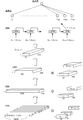
- FIG. 6 shows an example in which a signal similar to the sound wave signal Ss shown in FIG. 2 is represented by a graph having a time axis and an amplitude axis.
- FIG. 6 shows an example in which this graph is regarded as an image and binarized by setting a portion having an amplitude value at a plurality of positions in the time axis direction as 1 and a portion having no amplitude value as 0.
- the value at each position on the time axis of the time-varying signal is represented by a multidimensional amount, and various types of conversion to a multidimensional amount including this example are possible. May be adopted.
- the number of digits for expressing the value of each component of a multidimensional amount is not limited to 1.
- the value of a plurality of binary digits may be the value of one component.
- the method of interpreting one component before conversion may be performed by various methods. For example, when one component before conversion is one decimal value and it spans multiple digits, this value is decomposed into values for each digit and then n digits (n is an integer of 2 or more) for each digit.
- the value may be converted into a value, and the converted value may be the value of each component of the multidimensional amount, or each digit of the converted value may be the value of each component of the multidimensional amount.
- each of “8", “0”, and “6” is converted into the binary number "1000”.
- ", "0000”, “0110” may be set, and "1000", “0000”, and “0110” may be used as the respective values of the three components of the multidimensional amount.
- each digit of “100000000110” may be set as each value of 12 components of the multidimensional amount.
- Multi-dimensional quantity may be a value expressed by multiple components and may be determined by various methods. Also, the relationship for each component may be various relationships. For example, as in the above-described embodiment, each digit of the binary number expression may be a component, or each component may be an amount expressed so as to be linearly independent.
- the output unit is only required to be able to output the multidimensional amount as time series data including at least the values of the same component of the multidimensional amount at a plurality of consecutive positions. That is, the time-series data need only show how the values of the same multidimensional component change over time.
- the number of positions on the time axis (time length indicated by the time series data) represented by the time series data may be any number as long as it is plural. The number may be selected.
- the number of components is an integer in the range of 1 or more and the number of components of the multidimensional amount or less. Is.
- the number of components may be selected depending on the use of the time series data.
- the time-series data will be two-dimensional data.
- the values of different components at the same position on the time axis are arranged in the first axis direction, and the values of the same component at different positions on the time axis are different from the first axis direction.
- the configuration may be one in which two-dimensional data arranged in two axial directions is extracted.
- two-dimensional data including all 8-digit binary digits shown in the lower left may be extracted. That is, in the multidimensional amount shown in FIG. 2, the values of different components (digits) at the same position on the time axis are lined up when viewed in the vertical direction of the figure, so the vertical direction can be regarded as the first axis. Furthermore, when viewed in the left-right direction in the figure, the values of the same component are arranged at different positions on the time axis, so the left-right direction (time direction) can be regarded as the second axis.
- the machine-learned model 30b including the convolutional neural network that inputs the two-dimensional data is machine-learned. Further, based on the machine-learned model 30b including the convolutional neural network that inputs the two-dimensional data, information regarding the characteristics of the sound source of the signal is output.
- FIG. 7 is an example of a machine learning model for inputting two-dimensional data.
- the model is described so that the calculation proceeds from the lower part to the upper part.
- the initial three layers are composed of CNN.
- the output result by CNN is input to RNN, and the output by RNN reaches the output layer through full coupling.
- Two-dimensional data D 2D that is input data is illustrated at the bottom of FIG. 7.
- the number of positions on the time axis is arbitrary.
- the data can be the two-dimensional data D 2D. ..
- an operation of convolving the information in the time direction and the component direction (digit direction) of the two-dimensional data D 2D is performed. That is, a two-dimensional filter is prepared and applied to the two-dimensional data D 2D to perform the convolution operation.
- the size of the filter is represented by a cube having a size x in the time direction, a size y in the component direction, and a size ch in the channel direction. That is, the size of the filter in the CNN of the first layer is the size x 1 in the time direction, the size y 1 in the component direction, the size 1 in the channel direction, and the size of the filter in the CNN of the second layer is the size in the time direction.
- Size x 2 , component direction size y 2 , channel direction size 128, filter size in CNN of the third layer is time direction size x 3 , component direction size y 3 , channel direction size
- the size is 256.
- the number of filters in the CNN of the first layer is 128, the number of filters in the CNN of the second layer is 256, and the number of filters in the CNN of the third layer is 512.
- the size of the filters and the number of filters can be adjusted appropriately.
- the calculation of the neural network is sequentially performed. For example, when the convolution operation of the CNN of the first layer is performed, the output becomes i 1 ⁇ j 1 ⁇ 128 pieces of data, which becomes the input of the CNN of the second layer.
- the output of the second layer becomes i 2 ⁇ j 2 ⁇ 256 data
- the output of the third layer is i 3 ⁇ j 3 ⁇ 512 data.
- the element forming the RNN shown in FIG. 7 is a BiGRU (Bidirectional Gated Recurrent Unit)
- the element may be an LSTM or the like, and various configurations can be adopted.
- the hyperparameter may be various parameters.
- the data D CNN input to the RNN is input to the fully connected layer and the feature output at the layer next to the fully connected layer, for example, whether it is music or not.
- the classification result may be output.
- a machine learned model 30b that outputs sound characteristics with two-dimensional data as an input is obtained.
- the data output as time series data in step S110 shown in FIG. 4 is two-dimensional data.
- the control unit 20 acquires information indicating a model as shown in FIG. 7 as a training model in step S115. Then, if the control unit 20 performs the learning in step S135 through steps S120 to S130, the machine-learned model 30b that receives the two-dimensional data as an input and outputs the sound feature is obtained.
- step S215 when the control unit 20 inputs the two-dimensional data into the machine-learned model 30b, the characteristic of the sound is determined.
- the value of each position on the time axis is decomposed into a plurality of components and includes the time change of each component. Therefore, by performing the machine learning and the feature determination based on the two-dimensional data, it is possible to determine the feature of the sound by performing the machine learning that captures various temporal changes, and to accurately determine the feature of the sound. Can be judged.
- the output by the output unit may be performed for the same device or different devices. That is, as in the above-described embodiment, the output unit may be configured to output the result of converting the multidimensional amount into time-series data and further perform the calculation, or the output unit may be another device (for example, an external device). Output to a server or the like connected to the server).
- the method of expressing the value at each position on the time axis of a time-varying signal in a multidimensional amount and outputting time-series data indicating the time change for each component of the multidimensional amount is a program. It can also be applied as a method.
- the system, program, and method described above can be realized as a single device or a plurality of devices, and include various aspects. Further, it is possible to change as appropriate, such as a part being software and a part being hardware. Further, the invention can be realized as a recording medium of a program for controlling the system.
- the recording medium of the software may be a magnetic recording medium or a semiconductor memory, and any recording medium developed in the future can be considered in exactly the same way.
- the signal conversion system is configured as a system including at least the signal acquisition unit 20a, the conversion unit 20b, and the output unit 20c.
- the signal conversion system is provided with a characteristic output unit 20e that outputs information related to the characteristics of the input signal based on the machine-learned model 30b, and the characteristic output system is also provided to the signal conversion system.
- the machine learning system is configured so as to further include a machine learning unit 20d that performs machine learning on the machine learned model 30b that outputs information regarding the characteristics of.
- the signal conversion system according to this embodiment may be executable as a signal conversion program as described above.
Landscapes
- Engineering & Computer Science (AREA)
- Computational Linguistics (AREA)
- Signal Processing (AREA)
- Health & Medical Sciences (AREA)
- Audiology, Speech & Language Pathology (AREA)
- Human Computer Interaction (AREA)
- Physics & Mathematics (AREA)
- Acoustics & Sound (AREA)
- Multimedia (AREA)
- Artificial Intelligence (AREA)
- Evolutionary Computation (AREA)
- Measurement Of Mechanical Vibrations Or Ultrasonic Waves (AREA)
Priority Applications (1)
| Application Number | Priority Date | Filing Date | Title |
|---|---|---|---|
| JP2020571028A JP7286894B2 (ja) | 2019-02-07 | 2019-12-17 | 信号変換システム、機械学習システムおよび信号変換プログラム |
Applications Claiming Priority (2)
| Application Number | Priority Date | Filing Date | Title |
|---|---|---|---|
| JP2019-020267 | 2019-02-07 | ||
| JP2019020267 | 2019-02-07 |
Publications (1)
| Publication Number | Publication Date |
|---|---|
| WO2020162048A1 true WO2020162048A1 (ja) | 2020-08-13 |
Family
ID=71947094
Family Applications (1)
| Application Number | Title | Priority Date | Filing Date |
|---|---|---|---|
| PCT/JP2019/049337 Ceased WO2020162048A1 (ja) | 2019-02-07 | 2019-12-17 | 信号変換システム、機械学習システムおよび信号変換プログラム |
Country Status (2)
| Country | Link |
|---|---|
| JP (1) | JP7286894B2 (enExample) |
| WO (1) | WO2020162048A1 (enExample) |
Cited By (2)
| Publication number | Priority date | Publication date | Assignee | Title |
|---|---|---|---|---|
| JPWO2022113340A1 (enExample) * | 2020-11-30 | 2022-06-02 | ||
| JPWO2022113338A1 (enExample) * | 2020-11-30 | 2022-06-02 |
Citations (6)
| Publication number | Priority date | Publication date | Assignee | Title |
|---|---|---|---|---|
| JPS58100199A (ja) * | 1981-10-19 | 1983-06-14 | ボータン | 音声認識及び再生方法とその装置 |
| JPS6259946B2 (enExample) * | 1980-05-12 | 1987-12-14 | Sony Corp | |
| JP2003332914A (ja) * | 2001-08-23 | 2003-11-21 | Nippon Telegr & Teleph Corp <Ntt> | ディジタル信号符号化方法、復号化方法、これらの装置及びプログラム |
| JP2005524869A (ja) * | 2002-05-06 | 2005-08-18 | プロウス サイエンス エス.アー. | 音声認識手順 |
| JP2015095215A (ja) * | 2013-11-14 | 2015-05-18 | 株式会社デンソーアイティーラボラトリ | 学習装置、学習プログラム、及び学習方法 |
| JP2018517928A (ja) * | 2015-09-24 | 2018-07-05 | グーグル エルエルシー | 音声活動検出 |
Family Cites Families (1)
| Publication number | Priority date | Publication date | Assignee | Title |
|---|---|---|---|---|
| JP6259946B1 (ja) | 2017-07-20 | 2018-01-10 | 株式会社Nttドコモ | 機械学習システム、識別システム及びプログラム |
-
2019
- 2019-12-17 WO PCT/JP2019/049337 patent/WO2020162048A1/ja not_active Ceased
- 2019-12-17 JP JP2020571028A patent/JP7286894B2/ja active Active
Patent Citations (6)
| Publication number | Priority date | Publication date | Assignee | Title |
|---|---|---|---|---|
| JPS6259946B2 (enExample) * | 1980-05-12 | 1987-12-14 | Sony Corp | |
| JPS58100199A (ja) * | 1981-10-19 | 1983-06-14 | ボータン | 音声認識及び再生方法とその装置 |
| JP2003332914A (ja) * | 2001-08-23 | 2003-11-21 | Nippon Telegr & Teleph Corp <Ntt> | ディジタル信号符号化方法、復号化方法、これらの装置及びプログラム |
| JP2005524869A (ja) * | 2002-05-06 | 2005-08-18 | プロウス サイエンス エス.アー. | 音声認識手順 |
| JP2015095215A (ja) * | 2013-11-14 | 2015-05-18 | 株式会社デンソーアイティーラボラトリ | 学習装置、学習プログラム、及び学習方法 |
| JP2018517928A (ja) * | 2015-09-24 | 2018-07-05 | グーグル エルエルシー | 音声活動検出 |
Cited By (4)
| Publication number | Priority date | Publication date | Assignee | Title |
|---|---|---|---|---|
| JPWO2022113340A1 (enExample) * | 2020-11-30 | 2022-06-02 | ||
| JPWO2022113338A1 (enExample) * | 2020-11-30 | 2022-06-02 | ||
| WO2022113340A1 (ja) * | 2020-11-30 | 2022-06-02 | 日本電気株式会社 | 情報処理装置、情報処理方法、及び、記録媒体 |
| WO2022113338A1 (ja) * | 2020-11-30 | 2022-06-02 | 日本電気株式会社 | 情報処理装置、情報処理方法、及び、記録媒体 |
Also Published As
| Publication number | Publication date |
|---|---|
| JPWO2020162048A1 (enExample) | 2020-08-13 |
| JP7286894B2 (ja) | 2023-06-06 |
Similar Documents
| Publication | Publication Date | Title |
|---|---|---|
| CN111292764B (zh) | 辨识系统及辨识方法 | |
| CN110136744B (zh) | 一种音频指纹生成方法、设备及存储介质 | |
| WO2020028760A1 (en) | System and method for neural network orchestration | |
| Copiaco et al. | Scalogram neural network activations with machine learning for domestic multi-channel audio classification | |
| CN117033657A (zh) | 一种信息检索方法及装置 | |
| CN111816170A (zh) | 一种音频分类模型的训练和垃圾音频识别方法和装置 | |
| CN119538016B (zh) | 一种基于数据孪生的质谱检测方法及系统 | |
| JP7286894B2 (ja) | 信号変換システム、機械学習システムおよび信号変換プログラム | |
| CN116421152A (zh) | 一种睡眠分期结果确定方法、装置、设备及介质 | |
| KR20180066472A (ko) | 기계 학습을 이용한 음악 신호의 처리 방법 | |
| CN117351949A (zh) | 一种基于二阶循环神经网络的环境声音识别方法 | |
| CN110070891B (zh) | 一种歌曲识别方法、装置以及存储介质 | |
| CN113870896A (zh) | 基于时频图和卷积神经网络的运动声音判假方法、装置 | |
| CN107239482A (zh) | 一种将图像转换为音乐的处理方法及服务器 | |
| CN118227079B (zh) | 一种深度学习的均衡器参数自动生成方法、设备及介质 | |
| CN117975994A (zh) | 嗓音数据的质量分类方法、装置以及计算机设备 | |
| CN118038887A (zh) | 一种混合语音的处理方法、装置、计算机设备及存储介质 | |
| CN119004135A (zh) | 一种基于孪生网络的音视频场景协同方法、装置及介质 | |
| US20250131914A1 (en) | Learning apparatus, conversion apparatus, learning method and program | |
| da Silva et al. | Audio plugin recommendation systems for music production | |
| Bala Ganesh et al. | GenreNet: A Deep Based Approach for Music Genre Classification | |
| Shetty et al. | Advancing Music Genre Identification Through Deep Learning Techniques | |
| CN120744427B (zh) | 一种辐射源小样本个体识别系统及方法 | |
| Ashurov et al. | Classification of Environmental Sounds Through Spectrogram-Like Images Using Dilation-Based CNN | |
| CN118542644B (zh) | 一种基于ai和音频的声带疾病状态的识别方法和装置 |
Legal Events
| Date | Code | Title | Description |
|---|---|---|---|
| 121 | Ep: the epo has been informed by wipo that ep was designated in this application |
Ref document number: 19914507 Country of ref document: EP Kind code of ref document: A1 |
|
| DPE1 | Request for preliminary examination filed after expiration of 19th month from priority date (pct application filed from 20040101) | ||
| ENP | Entry into the national phase |
Ref document number: 2020571028 Country of ref document: JP Kind code of ref document: A |
|
| NENP | Non-entry into the national phase |
Ref country code: DE |
|
| 122 | Ep: pct application non-entry in european phase |
Ref document number: 19914507 Country of ref document: EP Kind code of ref document: A1 |