WO2020162048A1 - Signal conversion system, machine learning system, and signal conversion program - Google Patents
Signal conversion system, machine learning system, and signal conversion program Download PDFInfo
- Publication number
- WO2020162048A1 WO2020162048A1 PCT/JP2019/049337 JP2019049337W WO2020162048A1 WO 2020162048 A1 WO2020162048 A1 WO 2020162048A1 JP 2019049337 W JP2019049337 W JP 2019049337W WO 2020162048 A1 WO2020162048 A1 WO 2020162048A1
- Authority
- WO
- WIPO (PCT)
- Prior art keywords
- signal
- time
- data
- values
- machine learning
- Prior art date
Links
Images
Classifications
-
- G—PHYSICS
- G10—MUSICAL INSTRUMENTS; ACOUSTICS
- G10L—SPEECH ANALYSIS OR SYNTHESIS; SPEECH RECOGNITION; SPEECH OR VOICE PROCESSING; SPEECH OR AUDIO CODING OR DECODING
- G10L25/00—Speech or voice analysis techniques not restricted to a single one of groups G10L15/00 - G10L21/00
- G10L25/27—Speech or voice analysis techniques not restricted to a single one of groups G10L15/00 - G10L21/00 characterised by the analysis technique
- G10L25/30—Speech or voice analysis techniques not restricted to a single one of groups G10L15/00 - G10L21/00 characterised by the analysis technique using neural networks
-
- G—PHYSICS
- G10—MUSICAL INSTRUMENTS; ACOUSTICS
- G10L—SPEECH ANALYSIS OR SYNTHESIS; SPEECH RECOGNITION; SPEECH OR VOICE PROCESSING; SPEECH OR AUDIO CODING OR DECODING
- G10L25/00—Speech or voice analysis techniques not restricted to a single one of groups G10L15/00 - G10L21/00
- G10L25/48—Speech or voice analysis techniques not restricted to a single one of groups G10L15/00 - G10L21/00 specially adapted for particular use
- G10L25/51—Speech or voice analysis techniques not restricted to a single one of groups G10L15/00 - G10L21/00 specially adapted for particular use for comparison or discrimination
Definitions
- the present invention relates to a signal conversion system, a machine learning system, and a signal conversion program.
- Patent Document 1 discloses a technique of converting a numerical value indicating input information into a binary bit sequence. Specifically, a configuration is disclosed in which the numerical value of an ID indicating a word is converted into a binary bit sequence.
- the signal conversion system includes a signal acquisition unit that acquires a signal that is a time-varying signal and in which each of the values at a plurality of positions on the time axis is represented by one component, A conversion unit that converts each of the values for each of the plurality of positions into a multidimensional amount expressed by the values of the plurality of components, and the multidimensional amount is at least the value of the same component of the multidimensional amount at a plurality of consecutive positions.
- L is an integer that is 1 or more and is equal to or less than the number of components of a multidimensional quantity
- the conversion unit converts a signal in which the value of one position on the time axis is expressed by one component into a multidimensional amount expressed by the values of multiple components.
- the signal can be expressed in a format capable of capturing more various characteristics than the original signal.
- the output unit outputs the multidimensional amount as L pieces of time-series data including at least values of the same component of the multidimensional amount at a plurality of consecutive positions on the time axis. Further, by applying the L time-series data to a machine learning model, information regarding the characteristics of the signal is output.
- the time change of the values of the same component of the multidimensional amount is shown, and the feature of the time change of the signal can be grasped for each component.
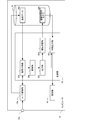
- FIG. 1 is a diagram showing a schematic configuration of a computer 10 that functions as a signal conversion system, a feature output system, and a machine learning system according to an embodiment of the present invention.
- the computer 10 includes a microphone 10a, an A/D conversion unit 10b, a control unit 20, a storage medium 30, and a display unit 40.
- the control unit 20 includes a CPU, a RAM, and a ROM (not shown), and can execute various programs stored in the storage medium 30 or the like.
- the microphone 10a, the A/D conversion unit 10b, the control unit 20, the storage medium 30, and the display unit 40 may be configured as an integrated computer, or at least a part of them may be different devices, such as a USB cable. It may be connected.
- the computer 10 may have various modes, for example, a stationary general-purpose computer or a portable computer such as a smartphone or a tablet terminal.
- the microphone 10a collects ambient sound and outputs an analog sound wave signal indicating a temporal change in sound pressure.
- the A/D conversion unit 10b is a device that converts an analog signal into a digital signal, and samples the analog sound wave signal at the sampling frequency instructed by the control unit 20 and outputs it as a digital sound wave signal.
- the digital sound wave signal is composed of sound pressure amplitude values at a plurality of positions on the time axis, and the amplitude values are represented by decimal numbers. Therefore, the digital sound wave signal is a signal in which each of the values at a plurality of positions on the time axis is represented by one component.
- the storage medium 30 is a medium capable of storing various kinds of information, and in the present embodiment, the teacher data 30a for machine learning is stored in the storage medium 30.
- the machine-learned model is generated by machine learning, information indicating the model is stored in the storage medium 30 as the machine-learned model 30b.
- the display unit 40 is a display that displays various types of information.
- control unit 20 can execute the signal conversion program.
- the signal conversion program is a program that causes the control unit 20 to execute the function of converting and outputting a time-varying signal. Further, in the present embodiment, the signal conversion program has a function of performing machine learning based on the converted signal, and a function of outputting a characteristic of sound based on the converted signal.
- the control unit 20 When the signal conversion program is executed, the control unit 20 functions as the signal acquisition unit 20a, the conversion unit 20b, the output unit 20c, the machine learning unit 20d, and the feature output unit 20e.
- the type of sound source is output as a feature of the sound source. That is, the control unit 20 can classify the types of sound sources. Although the number of classifications may be arbitrary, here, an example of classifying whether or not the sound source is music will be described.
- machine learning is used to classify the types of sound sources. That is, the machine-learned model 30b is generated in advance before the classification, and the classification result is output by inputting the digital signal indicating the sound to be classified into the machine-learned model 30b. In order to perform such classification accurately, it is preferable to use a digital signal capable of capturing detailed characteristics of sound as an input value to the machine-learned model 30b.
- the control unit 20 has a function of converting a digital sound wave signal indicating a sound into a multidimensional amount and outputting it as time series data capable of capturing detailed characteristics of the sound.
- An example of the time-series data is a data string surrounded by a dotted line in FIG. Details will be described later.
- the machine learning is performed using the time series data, and the sound is classified with high accuracy by performing the classification using the time series data. That is, in the present embodiment, time series data is used as input data when learning a machine learning target model, and time series data is also used as input data for performing classification based on the machine learned model 30b. Is used.
- the generation of the time series data is realized by the control unit 20 executing the functions of the signal acquisition unit 20a, the conversion unit 20b, and the output unit 20c. Further, the machine learning using the time series data is realized by the control unit 20 executing the function of the machine learning unit 20d. Furthermore, the classification of sound source types using time-series data is realized by the control unit 20 executing the function of the feature output unit 20e. In the following, machine learning and sound source type classification (feature output) will be described in order.
- the teacher data 30a is prepared in advance for machine learning.
- the teacher data 30a is information in which a sound wave signal is associated with a sound source type of a sound indicated by the sound wave signal. For example, a set of data in which a sound wave signal indicating music is associated with music, and a set of data in which a sound wave signal indicating a sound other than music (human utterances, etc.) is associated with not music
- the data can be the teacher data 30a.
- a sufficient amount of data for machine learning is prepared in advance.
- the teacher data 30a may be prepared by various methods, for example, data acquired by a plurality of clients may be collected by a server or the like.
- the computer 10 can also generate the teacher data 30a. That is, the sound is collected by the microphone 10a included in the computer 10, the information indicating the type of the sound source is associated with the digital sound wave signal converted by the A/D conversion unit 10b, and is stored as the teacher data 30a in the storage medium 30. May be remembered.
- the teacher data 30a the values indicating the sound pressures at a plurality of positions on the time axis are expressed in decimal numbers.
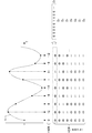
- FIG. 2 is a diagram for explaining data conversion.
- a part of the sound wave signal Ss is shown on the graph.
- the A/D conversion unit 10 b converts the sound wave signal into a digital sound wave signal at the sampling frequency instructed by the control unit 20.
- the black circles superimposed on the sound wave signal Ss indicate the sampled amplitude, and the sampling value is shown below it.
- the first sampling value is 0 in decimal and the second sampling value is 12 in decimal.
- information (label) indicating the type of sound source is associated with the set of values at a plurality of positions on the time axis thus obtained.
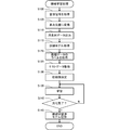
- the machine learning process is a process of optimizing a training model forming a neural network, and in the present embodiment, the machine learning process is executed according to the flowchart shown in FIG.
- the model is information indicating an equation for deriving the correspondence between the classification target data and the classification result data
- the classification result is whether or not music.
- the classification target is the time-series data converted and output from the sound wave signal. That is, in the present embodiment, when a digital sound wave signal (decimal number expression) that has been A/D converted by the A/D conversion unit 10b is not directly input to the model of machine learning, but is converted and output. Enter the series data.
- the control unit 20 includes a signal acquisition unit 20a, a conversion unit 20b, and an output unit 20c in order to perform processing using time-series data as described above.
- the signal acquisition unit 20a causes the control unit 20 to perform a function of acquiring a signal that is a time-varying signal and in which each of the values at a plurality of positions on the time axis is expressed by one component.
- the time-varying signal is a signal in which a sound wave signal is sampled at a predetermined sampling frequency and expressed as a decimal value, and in machine learning, the teacher data 30a corresponds to the signal.
- control unit 20 refers to the storage medium 30 and acquires a sound wave signal from each teacher data 30a (step S100).
- a plurality of data sets in which the amplitudes of the sound wave signal at a plurality of positions on the time axis are expressed in decimal are obtained.
- the conversion unit 20b is a program module that causes the control unit 20 to execute a function of converting each value at each of a plurality of positions into a multidimensional amount expressed by a plurality of component values. That is, since the expression of the amplitude by the decimal number indicates the magnitude of the amplitude at a certain position on the time axis by one component, the control unit 20 expresses the sound wave signal by a larger number of components, and thus the sound wave is generated. The signal is converted into a multidimensional quantity (step S105).
- the control unit 20 determines the magnitude of the amplitude at each position on the time axis. Is converted to a binary value. That is, each digit of the converted binary number becomes a multidimensional component.
- the converted binary value (8 bits) is shown below the value indicating the amplitude of the sound pressure.
- the lower digits to the upper digits are displayed so as to be arranged from the upper side to the lower side.
- the first sampled value of decimal 0 is binary number 00000000
- the second sampled value of decimal 12 is binary number 00001100.
- the time length of the actual digital sound wave signal is longer than the time length shown in FIG. 2, and for example, the digital sound wave signal is composed of 1 second of data (10000 pieces of data) sampled at 10 kHz.
- the digital sound wave signal is a conversion target.
- the output unit 20c is a program module that causes the control unit 20 to execute a function of outputting a multidimensional amount as time-series data including at least values of the same component of the multidimensional amount at a plurality of consecutive positions.
- the digit of the binary value converted in step S105 is regarded as a component, and the control unit 20 extracts the value of each digit by the function of the output unit 20c to obtain the time series data.
- Output step S110).
- the least significant digit of the multidimensional amount represented by a binary number is surrounded by a dashed line.
- the control unit 20 generates data in which the respective values existing at different positions on the time axis in the least significant digit are arranged in the order on the time axis as the time series data D 1 of the least significant digit component.
- the time-series data is one-dimensional data indicating the time change of the value of the same component.
- One-dimensional data may be implemented for multi-dimensional quantities of each component. That is, when the time series data is extracted for the upper digit of the binary number, the time series data shows a large change in the amplitude of the digital sound wave signal. On the other hand, when the time series data is extracted for the lower digit of the binary number, the time series data indicates a fine change in the amplitude of the digital sound wave signal.
- the number of components to be extracted as time-series data may be selected from an integer equal to or greater than 1 and equal to or less than the number of components of a multidimensional amount according to the purpose of machine learning or a classification target.
- time-series data is output for all 8-digit binary components (all digits). Therefore, FIG. 2 shows that the time series data D 2 to D 8 are output in addition to the time series data D 1 .
- the sound is classified based on the time series data output as described above. That is, a machine learning process for optimizing a model for inputting time series data by machine learning is performed.
- Machine learning may be performed by various methods, but in the present embodiment, machine learning is performed by a neural network including a convolutional neural network (CNN: Convolutional Neural Network) and a recurrent neural network (RNN: Recurrent Neural Network).
- CNN convolutional neural network
- RNN Recurrent Neural Network
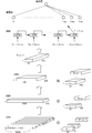
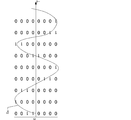
- FIG. 3 is a diagram showing an example of a model applicable to the example shown in FIG. In FIG. 3, the model is described so that the calculation proceeds from the lower part to the upper part.
- the initial three layers are composed of CNN.
- the output result by CNN is input to RNN, and the output by RNN reaches the output layer through full coupling.
- time-series data D 1 to D 8 for 8 channels which are input data are illustrated.
- digital sound wave signals obtained by sampling 10,000 positions on the time axis, that is, 10,000 times at 10 kHz are converted and output as time-series data.
- a calculation for convoluting the time-series data D 1 to D 8 in the time direction is performed.
- each of the time series data D 1 to D 8 is one-dimensional time series data and has a total of 8 channels. Therefore, in the present embodiment, a two-dimensional (time axis direction and channel direction) filter is prepared and the convolution operation is performed.
- the filter is two-dimensional, and is a filter that convolves 30 ⁇ 8 values (values of 30 consecutive positions on the time axis for 8 channels).
- the size of the filter is shown as 1 ⁇ 30 ⁇ 8.
- the size of the filter is not limited to 30, and may be, for example, 50, 40, 20 or 10, or may be in a range between any two of these exemplified numerical values. The shorter the filter size, the earlier the processing after signal acquisition can be started.
- the input data is eight channels, but it is not limited to eight.
- the number of filters is not limited, the number of filters in the first layer of CNN is 128 in the example shown in FIG. In FIG. 3, these filters are shown as F 1-1 to F 1-128 .
- a filter having a short size in the time axis direction can be used as described above, it is possible to capture a minute change in time series data as compared with the conventional technique.
- a filter having a short size in the time axis direction directly causes a minute amplitude change or a global amplitude time change. Is difficult to capture.
- the Fourier transform or the like if a short-term signal is used in the time space, the accuracy of the information in the frequency space will decrease. That is, more time is required from the acquisition of the signal to the output of the feature.
- Each filter is applied to each of the time series data D 1 to D 8 with a predetermined padding or stride. For example, if the stride 10 is appropriately padded, the 10,000 data will be 1,000. The output result of one filter is obtained by adding these. Therefore, when the number of filters is 128, 128 one-dimensional data having 1000 data are generated. In FIG. 3, the 1 ⁇ 1000 ⁇ 128 data is indicated by a rectangle. Of course, hyperparameters such as stride and padding are examples, and the number of output data (1000 pieces, etc.) is also an example (same for other layers).
- FIG. 3 shows an example in which 256 filters of size 1 ⁇ 30 ⁇ 128 are prepared in the second layer, and 512 filters of size 1 ⁇ 30 ⁇ 256 are further prepared in the third layer. ing. Stride and padding are similar to the first layer.
- 1 ⁇ 10 ⁇ 512 pieces of data D CNN are output by the above-described calculation of the three layers.
- the data D CNN becomes an input to the RNN.
- the element forming the RNN shown in FIG. 3 is an LSTM (Long Short-Term Memory)
- the element may be a GRU (Gated Recurrent Unit) or a bidirectional model may be adopted.
- a configuration can be adopted.
- the hyperparameter may be various parameters.
- the LSTM outputs 1024, and the data Y 1 to Y 1024 output from the last LSTM are input to the next layer. That is, the data Y 1 to Y 1024 are input to the fully connected layer, and the classification result indicating whether or not the layer is the music next to the fully connected layer is output.
- the control unit 20 executes the machine learning process based on the above model by the function of the machine learning unit 20d. That is, the control unit 20 machine-learns a machine-learned model that receives time-series data and outputs information related to the characteristics of the sound source of the signal by the function of the machine learning unit 20d. Specifically, the control unit 20 acquires the training model by the function of the machine learning unit 20d (step S115). That is, various kinds of information corresponding to the structure of the neural network as shown in FIG. 3 (information such as a filter indicating a model and an activation function) is defined in advance, and the control unit 20 acquires the information. Get the training model.
- the control unit 20 acquires the label of the teacher data 30a by the function of the machine learning unit 20d (step S120). That is, the control unit 20 acquires the label indicating the type of the sound source of each sound wave signal acquired in step S100. For example, in the example shown in FIG. 3, the label indicates whether the output value of the node in the output layer is 1, 0, and when the sound source of the sound wave signal acquired in step S100 is music. 1, 0 is acquired when it is a sound other than music.
- control unit 20 acquires test data by the function of the machine learning unit 20d (step S125).
- the control unit 20 extracts a part of the data acquired in step S110, and associates the label acquired in step S120 with it to make it test data.
- the test data is data for confirming whether or not learning generalization has been performed, and is not used for machine learning.
- control unit 20 determines the initial value by the function of the machine learning unit 20d (step S130). That is, the control unit 20 gives initial values to the variable parameters (filter weight, bias, etc.) to be learned in the training model acquired in step S115.
- the initial value may be determined by various methods. Of course, the initial values may be adjusted so that the parameters are optimized during the learning process, or the learned parameters may be acquired from various databases and used.
- control unit 20 performs learning by the function of the machine learning unit 20d (step S135). That is, the control unit 20 inputs the time-series data output in step S110 to the training model acquired in step S115, and outputs information indicating the classification result. When the information indicating the classification result is output, the control unit 20 specifies the error by the loss function indicating the error between the output and the label acquired in step S120. When the loss function is obtained, the control unit 20 updates the parameter by a predetermined optimization algorithm, for example, the stochastic gradient descent method. That is, the control unit 20 repeats the process of updating the parameter based on the differentiation of the loss function by the parameter for a predetermined number of times.
- a predetermined optimization algorithm for example, the stochastic gradient descent method. That is, the control unit 20 repeats the process of updating the parameter based on the differentiation of the loss function by the parameter for a predetermined number of times.
- the control unit 20 determines whether or not the generalization of the training model has been completed (step S140). That is, the control unit 20 inputs the test data acquired in step S125 into the training model and outputs the sound wave signal classification result. Then, the control unit 20 obtains the number of coincidences between the output classification result and the classification result associated with the test data (the number of errors between the classification result and the label is equal to or less than the default value), The classification accuracy is obtained by dividing by the number of samples. In the present embodiment, the control unit 20 determines that the generalization is completed when the classification accuracy is equal to or higher than the threshold value.
- the validity of hyperparameters may be verified. That is, in a configuration in which a hyperparameter that is a variable amount other than the variable parameter to be learned, such as the filter size and the number of nodes, is tuned, the control unit 20 determines the validity of the hyperparameter based on the verification data. You may verify.
- the verification data may be acquired by preliminarily extracting the verification data by the same process as in step S125 and securing it as data not used for training.
- step S140 If it is not determined in step S140 that the generalization of the training model is completed, the control unit 20 repeats step S135. That is, the process of further updating the variable parameter to be learned is performed. On the other hand, when it is determined in step S140 that the generalization of the training model is completed, the control unit 20 records the machine-learned model (step S145). That is, the control unit 20 records the training model in the storage medium 30 as the machine-learned model 30b.
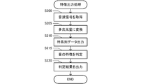
- the control unit 20 acquires a sound wave signal (step S200). That is, when a sound wave is output from the sound source, the microphone 10a acquires the sound wave and outputs an analog sound wave signal.
- the control unit 20 preliminarily instructs the A/D conversion unit 10b to have the same sampling frequency as that used for machine learning.
- the A/D converter 10b samples the analog sound wave signal at the sampling frequency and converts it into a digital sound wave signal.
- the control unit 20 acquires the digital sound wave signal by the function of the signal acquisition unit 20a. For example, in the case of the sound wave signal Ss shown in FIG. 2, since the A/D conversion unit 10b outputs a decimal sound wave signal (0, 12, 6,,... ), the control unit 20 controls the digital sound signal Ss. Acquire sound wave signals.
- the control unit 20 converts the sound wave signal into a multidimensional amount by the function of the A/D conversion unit 10b (step S205). That is, the control unit 20 acquires the digital sound wave signal acquired in step S200, and converts the decimal value indicating the amplitude of each of a plurality of positions on the time axis into a binary number. For example, in step S200, when the digital sound wave signals (0, 12, 6,,,) shown in FIG. 2 are acquired, the binary multidimensional quantity (000000000001100,,,) shown in FIG. 2 is obtained. To be acquired.
- control unit 20 outputs the time series data by the function of the output unit 20c (step S210). That is, the control unit 20 extracts a value for each digit of the multidimensional amount and generates time-series data of each digit. For example, in the example shown in FIG. 2, the control unit 20 acquires the time series data D 1 to D 8 .
- the control unit 20 determines the feature of the sound by the function of the feature output unit 20e (step S215). That is, the control unit 20 acquires the machine-learned model 30b and inputs the time-series data D 1 to D 8 output in step S210 to the machine-learned model 30b.
- the control unit 20 uses the parameters indicated by the machine-learned model 30b to calculate CNN, RNN, etc. shown in FIG. As a result, the value of the output layer is determined.
- the time-series data D 1 to D 8 which are eight- dimensional one-dimensional data are input to the machine-learned model 30b, but the number of channels is not limited to eight. It may be an integer greater than or equal to 1 and less than or equal to the number of multidimensional components.
- the control unit 20 compares the value of the output layer with the threshold value, and determines that the sound source type is music if the threshold value or more, and determines that the sound source type is not music if it is smaller than the threshold value. For example, when the value of the output layer changes in the range of 0 to 1 and the threshold value is 0.9 and the value of the output layer is 0.9 or more, the control unit 20 determines that the sound source type is music. To consider.
- control unit 20 outputs the determination result by the function of the feature output unit 20e (step S220). That is, the control unit 20 controls the display unit 40 to display information indicating the type of sound source.
- the characteristic of the sound can be determined based on the result of machine learning by converting the amplitude represented by the decimal number into the multidimensional amount represented by the value of a larger number of components. Therefore, it is possible to determine the characteristics of the sound by performing machine learning that captures more various characteristics than the original signal represented by a decimal number, and it is possible to determine the characteristics of the sound with high accuracy.
- the multidimensional amount is decomposed for each same component (each same digit), and machine learning and feature acquisition are performed using time-series data showing a time change of the value of the same component.
- the time change of the sound wave signal including both the global time change and the minute time change can be captured in detail. Therefore, it is possible to determine the characteristics of the sound by performing machine learning that captures various temporal changes more than the original signal represented by a decimal number, and it is possible to determine the characteristics of the sound with high accuracy.
- the minute time change is noise and the signal features appear in the portion excluding the minute time change, learning is performed so that the weight given to the classification by the minute time change becomes small. Therefore, the characteristics of the sound can be determined with high accuracy even if noise is included.
- the classification accuracy is compared between the case where environmental sound event classification is performed using this embodiment and the case where environmental sound event classification is performed using a known method.
- environmental sounds we used a database containing 28 types of events listed in Table 2 of the reference. Based on this database, as described in the reference document, three channels of the power spectrum (256 dimensions) and their variations ⁇ and ⁇ are input to the classification model, and an example of classifying the environmental sound event is made proportional.
- the classification model in this case is a model in which the result of passing through 6 layers of CNN is passed through through 3 layers of fully connected layers. The classification accuracy when machine learning was performed using the classification model was 80.3%.
- the above embodiment is an example for carrying out the present invention, in which the value at each position on the time axis of a signal that changes with time is represented by a multidimensional amount, and a time series indicating the time change for each component of the multidimensional amount.
- Various other embodiments can be adopted as long as data is output.
- the signal conversion system, the machine learning system, and the feature output system are configured by one computer 10, they may be different systems, or two systems are configured as one system. May be done.
- the method of linking separate systems may be various methods, and may be configured as a client and a server. Furthermore, at least a part of the signal acquisition unit 20a, the conversion unit 20b, the output unit 20c, the machine learning unit 20d, and the feature output unit 20e may be present separately in a plurality of devices.
- the configuration may be such that the process of acquiring the teacher data 30a by the signal acquisition unit 20a and the process of acquiring the classification target digital sound wave signal are performed by different devices.
- a part of the configuration of the above-described embodiment may be omitted, or the order of processing may be changed or omitted.
- a system may be configured in which the information obtained in the process of processing by the machine learning model shown in the above embodiment is output.
- the data D CNN of CNN is obtained in the course of the model shown in FIG. 3, the data D CNN may be output as the information indicating the characteristics of the sound. Since the information indicates the feature of the sound, if the pattern of the data D CNN in the case of the specific sound type is specified in advance, the sound type can be classified.
- the model for machine learning is not limited to the example shown in FIG. 3.
- the RNN is omitted, the CNN data D CNN is input to the fully connected layer, and the information indicating the classification result is output in the subsequent layers. It may be configured to be.
- the mode of machine learning is not limited.
- Machine learning may be performed by appropriately selecting various elements such as the type of a stride, the type of stride, the presence or absence of a pooling layer, the presence or absence of a fully connected layer, and the presence or absence of a recursive structure.
- learning may be performed by other machine learning, for example, deep learning, support vector machine, clustering, reinforcement learning, or the like.
- machine learning may be performed in which the structure of the model (for example, the number of layers or the number of nodes for each layer) is automatically optimized.
- the classification mode is not limited to music and non-music, and may be classification of music and voice, or classification of more kinds of sound sources.
- the uses of the signal conversion system, the machine learning system, and the feature output system are not limited to the classification of sound source types.
- it may be used for abnormal sound detection such as tap sound inspection, may be used for detailed classification of music (genre classification, song name classification, etc.), may be used for voice recognition, and may be used for sound recognition. May be used to classify related events (classification of types of environmental sounds).
- the use scene is not limited, and may be used for statistical management of broadcast contents by, for example, classifying broadcast audio.
- the present invention can also be applied to sound source separation.
- the signal acquisition unit should be able to acquire a signal that is a time-varying signal and in which each of the values at a plurality of positions on the time axis is represented by one component. That is, the signal acquisition unit acquires a signal in which the value at each position on the time axis is represented by a single component.
- the component indicates the feature of the signal, and if the component is one, the signal is represented by one feature. Therefore, as in the above-described embodiment, the amplitude of the sound wave signal is sampled at regular intervals, and a signal having one value (scalar amount) at one location on the time axis is represented by one component. It is a signal that has been processed. In addition, other various modes can be adopted as the signal represented by one component.
- the time-varying signal is not limited to a sound wave, as long as the signal can have different values at different positions on the time axis.
- a biological signal such as an ultrasonic wave, an electroencephalogram, an electrocardiogram, an electromyogram, or an arbitrary wave such as an environmental signal such as temperature, humidity, or atmospheric pressure can be a time-varying signal.
- the information indicating the change over time of the target may correspond to a signal that changes over time.
- image signals such as moving images.
- the moving image is represented by the time-series change of a plurality of images.
- each image in the case of a color image, the color of one pixel is expressed by three channels such as red, green, and blue, and in the case of a gray image, the brightness of one pixel is expressed by one channel.
- Has a gradation value (usually a value of 0 to 255). Therefore, it is also possible to adopt a configuration in which the gradation values of these pixels are converted into a multidimensional amount and the time-series data indicating the values of the respective converted components are output.
- the features output in the embodiment of the present invention may be used for various purposes other than classification and recognition, and may be used for prediction of future signal changes, for example.
- the feature of the signal that changes with time is not limited to the configuration in which the type of the sound source is used, and various features of the signal may be output by the feature output unit.
- the position on the time axis may be a discrete position, and the interval may be any interval.
- the sampling cycle is arbitrary, and the sampling cycle may be fixed or may change with time.
- the conversion unit only needs to be able to convert each of the values at each of the multiple positions into a multidimensional amount represented by the values of multiple components. That is, the conversion unit converts one value at each position on the time axis into a plurality of values at each position on the time axis.
- the conversion into the multidimensional amount may be performed by various methods. That is, various configurations may be adopted other than the configuration in which one value at each position on the time axis is converted into a binary number and each digit of the converted value becomes each component of the multidimensional amount.
- FIG. 6 shows an example in which a signal similar to the sound wave signal Ss shown in FIG. 2 is represented by a graph having a time axis and an amplitude axis.
- FIG. 6 shows an example in which this graph is regarded as an image and binarized by setting a portion having an amplitude value at a plurality of positions in the time axis direction as 1 and a portion having no amplitude value as 0.
- the value at each position on the time axis of the time-varying signal is represented by a multidimensional amount, and various types of conversion to a multidimensional amount including this example are possible. May be adopted.
- the number of digits for expressing the value of each component of a multidimensional amount is not limited to 1.
- the value of a plurality of binary digits may be the value of one component.
- the method of interpreting one component before conversion may be performed by various methods. For example, when one component before conversion is one decimal value and it spans multiple digits, this value is decomposed into values for each digit and then n digits (n is an integer of 2 or more) for each digit.
- the value may be converted into a value, and the converted value may be the value of each component of the multidimensional amount, or each digit of the converted value may be the value of each component of the multidimensional amount.
- each of “8", “0”, and “6” is converted into the binary number "1000”.
- ", "0000”, “0110” may be set, and "1000", “0000”, and “0110” may be used as the respective values of the three components of the multidimensional amount.
- each digit of “100000000110” may be set as each value of 12 components of the multidimensional amount.
- Multi-dimensional quantity may be a value expressed by multiple components and may be determined by various methods. Also, the relationship for each component may be various relationships. For example, as in the above-described embodiment, each digit of the binary number expression may be a component, or each component may be an amount expressed so as to be linearly independent.
- the output unit is only required to be able to output the multidimensional amount as time series data including at least the values of the same component of the multidimensional amount at a plurality of consecutive positions. That is, the time-series data need only show how the values of the same multidimensional component change over time.
- the number of positions on the time axis (time length indicated by the time series data) represented by the time series data may be any number as long as it is plural. The number may be selected.
- the number of components is an integer in the range of 1 or more and the number of components of the multidimensional amount or less. Is.
- the number of components may be selected depending on the use of the time series data.
- the time-series data will be two-dimensional data.
- the values of different components at the same position on the time axis are arranged in the first axis direction, and the values of the same component at different positions on the time axis are different from the first axis direction.
- the configuration may be one in which two-dimensional data arranged in two axial directions is extracted.
- two-dimensional data including all 8-digit binary digits shown in the lower left may be extracted. That is, in the multidimensional amount shown in FIG. 2, the values of different components (digits) at the same position on the time axis are lined up when viewed in the vertical direction of the figure, so the vertical direction can be regarded as the first axis. Furthermore, when viewed in the left-right direction in the figure, the values of the same component are arranged at different positions on the time axis, so the left-right direction (time direction) can be regarded as the second axis.
- the machine-learned model 30b including the convolutional neural network that inputs the two-dimensional data is machine-learned. Further, based on the machine-learned model 30b including the convolutional neural network that inputs the two-dimensional data, information regarding the characteristics of the sound source of the signal is output.
- FIG. 7 is an example of a machine learning model for inputting two-dimensional data.
- the model is described so that the calculation proceeds from the lower part to the upper part.
- the initial three layers are composed of CNN.
- the output result by CNN is input to RNN, and the output by RNN reaches the output layer through full coupling.
- Two-dimensional data D 2D that is input data is illustrated at the bottom of FIG. 7.
- the number of positions on the time axis is arbitrary.
- the data can be the two-dimensional data D 2D. ..
- an operation of convolving the information in the time direction and the component direction (digit direction) of the two-dimensional data D 2D is performed. That is, a two-dimensional filter is prepared and applied to the two-dimensional data D 2D to perform the convolution operation.
- the size of the filter is represented by a cube having a size x in the time direction, a size y in the component direction, and a size ch in the channel direction. That is, the size of the filter in the CNN of the first layer is the size x 1 in the time direction, the size y 1 in the component direction, the size 1 in the channel direction, and the size of the filter in the CNN of the second layer is the size in the time direction.
- Size x 2 , component direction size y 2 , channel direction size 128, filter size in CNN of the third layer is time direction size x 3 , component direction size y 3 , channel direction size
- the size is 256.
- the number of filters in the CNN of the first layer is 128, the number of filters in the CNN of the second layer is 256, and the number of filters in the CNN of the third layer is 512.
- the size of the filters and the number of filters can be adjusted appropriately.
- the calculation of the neural network is sequentially performed. For example, when the convolution operation of the CNN of the first layer is performed, the output becomes i 1 ⁇ j 1 ⁇ 128 pieces of data, which becomes the input of the CNN of the second layer.
- the output of the second layer becomes i 2 ⁇ j 2 ⁇ 256 data
- the output of the third layer is i 3 ⁇ j 3 ⁇ 512 data.
- the element forming the RNN shown in FIG. 7 is a BiGRU (Bidirectional Gated Recurrent Unit)
- the element may be an LSTM or the like, and various configurations can be adopted.
- the hyperparameter may be various parameters.
- the data D CNN input to the RNN is input to the fully connected layer and the feature output at the layer next to the fully connected layer, for example, whether it is music or not.
- the classification result may be output.
- a machine learned model 30b that outputs sound characteristics with two-dimensional data as an input is obtained.
- the data output as time series data in step S110 shown in FIG. 4 is two-dimensional data.
- the control unit 20 acquires information indicating a model as shown in FIG. 7 as a training model in step S115. Then, if the control unit 20 performs the learning in step S135 through steps S120 to S130, the machine-learned model 30b that receives the two-dimensional data as an input and outputs the sound feature is obtained.
- step S215 when the control unit 20 inputs the two-dimensional data into the machine-learned model 30b, the characteristic of the sound is determined.
- the value of each position on the time axis is decomposed into a plurality of components and includes the time change of each component. Therefore, by performing the machine learning and the feature determination based on the two-dimensional data, it is possible to determine the feature of the sound by performing the machine learning that captures various temporal changes, and to accurately determine the feature of the sound. Can be judged.
- the output by the output unit may be performed for the same device or different devices. That is, as in the above-described embodiment, the output unit may be configured to output the result of converting the multidimensional amount into time-series data and further perform the calculation, or the output unit may be another device (for example, an external device). Output to a server or the like connected to the server).
- the method of expressing the value at each position on the time axis of a time-varying signal in a multidimensional amount and outputting time-series data indicating the time change for each component of the multidimensional amount is a program. It can also be applied as a method.
- the system, program, and method described above can be realized as a single device or a plurality of devices, and include various aspects. Further, it is possible to change as appropriate, such as a part being software and a part being hardware. Further, the invention can be realized as a recording medium of a program for controlling the system.
- the recording medium of the software may be a magnetic recording medium or a semiconductor memory, and any recording medium developed in the future can be considered in exactly the same way.
- the signal conversion system is configured as a system including at least the signal acquisition unit 20a, the conversion unit 20b, and the output unit 20c.
- the signal conversion system is provided with a characteristic output unit 20e that outputs information related to the characteristics of the input signal based on the machine-learned model 30b, and the characteristic output system is also provided to the signal conversion system.
- the machine learning system is configured so as to further include a machine learning unit 20d that performs machine learning on the machine learned model 30b that outputs information regarding the characteristics of.
- the signal conversion system according to this embodiment may be executable as a signal conversion program as described above.
Abstract
[Problem] To provide a technology for generating data with which it is easy to identify features of temporal variation of a signal. [Solution] This signal conversion system is provided with: a signal acquisition unit for acquiring a time-variable signal in which values at multiple positions on the time axis are each represented by a single component; a conversion unit for converting each of the values at said multiple positions into a multidimensional quantity represented by a plurality of component values; an output unit for outputting said multidimensional quantity in the form of L pieces (L is an integer not less than 1 but not more than the number of components in the multidimensional quantity) of time-series data which at least include the values of identical components of the multidimensional quantity in a consecutive series of the multiple positions; and a feature output unit for outputting information concerning features of the signal on the basis of a machine-learned model which receives the L pieces of the time-series data as an input.
Description
本発明は、信号変換システム、機械学習システムおよび信号変換プログラムに関する。
The present invention relates to a signal conversion system, a machine learning system, and a signal conversion program.
従来、各種の分類や認識等に機械学習が利用されている。例えば、特許文献1には、入力情報を示す数値を2進数のビット系列に変換する技術が開示されている。具体的には、単語を示すIDの数値を2進数のビット系列に変換する構成が開示されている。
Conventionally, machine learning has been used for various types of classification and recognition. For example, Patent Document 1 discloses a technique of converting a numerical value indicating input information into a binary bit sequence. Specifically, a configuration is disclosed in which the numerical value of an ID indicating a word is converted into a binary bit sequence.
時間変化する信号に関して分類や認識、あるいは未来の信号変化の予測を精度良く実行するためには、当該信号の時間変化の特徴を詳細に捉えることが可能なフォーマットで信号を表現する必要があるが、従来、このような表現は知られていなかった。例えば、時間変化する波形信号の振幅をサンプリングして10進数の値で表現した場合、微細な振幅の変化や大局的な振幅の時間変化を直接的に捉えることは困難である。フーリエ変換等によって周波数空間の情報を得ようとしても、時間空間で短期間の信号を利用すると周波数空間の情報の精度が低下する。時間空間で長期間の信号を利用すると周波数空間の情報の精度が向上するが、短期間の信号の分類や認識に不適切な信号となってしまう。
本発明は、前記課題にかんがみてなされたもので、信号の時間変化の特徴を捉えやすいデータを生成する技術を提供することを目的とする。 In order to accurately classify or recognize a time-varying signal or predict future signal changes, it is necessary to represent the signal in a format that can capture the characteristics of the time-varying signal in detail. Conventionally, such an expression has not been known. For example, when the amplitude of a time-varying waveform signal is sampled and expressed by a decimal value, it is difficult to directly capture a minute amplitude change or a global amplitude time change. Even if an attempt is made to obtain frequency space information by Fourier transform or the like, if a short-term signal is used in the time space, the accuracy of the frequency space information decreases. Although the accuracy of frequency space information is improved by using a long-term signal in the time space, the signal becomes unsuitable for short-term signal classification and recognition.
The present invention has been made in view of the above problems, and an object of the present invention is to provide a technique for generating data that makes it easy to capture the characteristics of the temporal change of a signal.
上述の目的を達成するため、信号変換システムは、時間変化する信号であって、時間軸上の複数の位置における値のそれぞれが1個の成分で表現された信号を取得する信号取得部と、複数の位置毎の値のそれぞれを、複数の成分の値で表現した多次元量に変換する変換部と、多次元量を、連続する複数の位置における多次元量の同一の成分の値を少なくとも含む、L個(Lは1以上、多次元量の成分の数以下の整数)の時系列データとして出力する出力部と、L個の時系列データを入力する機械学習モデルに基づいて、信号の特徴に関する情報を出力する特徴出力部と、を備える。
In order to achieve the above-mentioned object, the signal conversion system includes a signal acquisition unit that acquires a signal that is a time-varying signal and in which each of the values at a plurality of positions on the time axis is represented by one component, A conversion unit that converts each of the values for each of the plurality of positions into a multidimensional amount expressed by the values of the plurality of components, and the multidimensional amount is at least the value of the same component of the multidimensional amount at a plurality of consecutive positions. Based on an output unit that outputs L pieces (L is an integer that is 1 or more and is equal to or less than the number of components of a multidimensional quantity) of time series data, and a machine learning model that inputs L pieces of time series data, And a feature output unit that outputs information about the feature.
すなわち、信号変換システムにおいては、時間軸上の1箇所の位置の値が1個の成分で表現された信号を、変換部が、複数の成分の値で表現した多次元量に変換する。この結果、元の信号よりも多様な特徴を捉えることが可能なフォーマットで信号を表現することができる。そして、出力部においては、多次元量を、時間軸上で連続する複数の位置における多次元量の同一の成分の値を少なくとも含むL個の時系列データとして出力する。さらに、当該L個の時系列データを機械学習モデルに適用することで信号の特徴に関する情報を出力する。すなわち、時系列データにおいては、多次元量の同一の成分の値の時間変化を示しており、成分毎に信号の時間変化の特徴を捉えることが可能である。このような構成によれば、信号の時間変化の特徴を捉えやすいデータを生成することが可能である。
That is, in the signal conversion system, the conversion unit converts a signal in which the value of one position on the time axis is expressed by one component into a multidimensional amount expressed by the values of multiple components. As a result, the signal can be expressed in a format capable of capturing more various characteristics than the original signal. Then, the output unit outputs the multidimensional amount as L pieces of time-series data including at least values of the same component of the multidimensional amount at a plurality of consecutive positions on the time axis. Further, by applying the L time-series data to a machine learning model, information regarding the characteristics of the signal is output. That is, in the time-series data, the time change of the values of the same component of the multidimensional amount is shown, and the feature of the time change of the signal can be grasped for each component. With such a configuration, it is possible to generate data in which it is easy to capture the characteristics of the time change of the signal.
ここでは、下記の順序に従って本発明の実施の形態について説明する。
(1)システムの構成:
(1-1)機械学習処理:
(1-2)特徴出力処理:
(2)他の実施形態: Here, an embodiment of the present invention will be described in the following order.
(1) System configuration:
(1-1) Machine learning processing:
(1-2) Feature output processing:
(2) Other embodiments:
(1)システムの構成:
(1-1)機械学習処理:
(1-2)特徴出力処理:
(2)他の実施形態: Here, an embodiment of the present invention will be described in the following order.
(1) System configuration:
(1-1) Machine learning processing:
(1-2) Feature output processing:
(2) Other embodiments:
(1)システムの構成:
図1は、本発明の一実施形態である信号変換システム、特徴出力システム、機械学習システムとして機能するコンピュータ10の概略構成を示す図である。コンピュータ10は、マイクロホン10a、A/D変換部10b、制御部20、記憶媒体30、表示部40を備えている。制御部20は、図示しないCPU,RAM,ROMを備えており、記憶媒体30等に記憶された各種プログラムを実行することができる。マイクロホン10a、A/D変換部10b、制御部20、記憶媒体30、表示部40は、一体的なコンピュータで構成されていても良いし、少なくとも一部が別の装置であり、USBケーブル等によって接続される構成であっても良い。コンピュータ10の態様は種々の態様であって良く、例えば、据置型の汎用コンピュータであっても良いし、スマートフォンやタブレット端末などの可搬型のコンピュータであっても良い。 (1) System configuration:
FIG. 1 is a diagram showing a schematic configuration of acomputer 10 that functions as a signal conversion system, a feature output system, and a machine learning system according to an embodiment of the present invention. The computer 10 includes a microphone 10a, an A/D conversion unit 10b, a control unit 20, a storage medium 30, and a display unit 40. The control unit 20 includes a CPU, a RAM, and a ROM (not shown), and can execute various programs stored in the storage medium 30 or the like. The microphone 10a, the A/D conversion unit 10b, the control unit 20, the storage medium 30, and the display unit 40 may be configured as an integrated computer, or at least a part of them may be different devices, such as a USB cable. It may be connected. The computer 10 may have various modes, for example, a stationary general-purpose computer or a portable computer such as a smartphone or a tablet terminal.
図1は、本発明の一実施形態である信号変換システム、特徴出力システム、機械学習システムとして機能するコンピュータ10の概略構成を示す図である。コンピュータ10は、マイクロホン10a、A/D変換部10b、制御部20、記憶媒体30、表示部40を備えている。制御部20は、図示しないCPU,RAM,ROMを備えており、記憶媒体30等に記憶された各種プログラムを実行することができる。マイクロホン10a、A/D変換部10b、制御部20、記憶媒体30、表示部40は、一体的なコンピュータで構成されていても良いし、少なくとも一部が別の装置であり、USBケーブル等によって接続される構成であっても良い。コンピュータ10の態様は種々の態様であって良く、例えば、据置型の汎用コンピュータであっても良いし、スマートフォンやタブレット端末などの可搬型のコンピュータであっても良い。 (1) System configuration:
FIG. 1 is a diagram showing a schematic configuration of a
マイクロホン10aは、周囲の音を集音し、音圧の時間変化を示すアナログ音波信号を出力する。A/D変換部10bは、アナログ信号をデジタル信号に変換する装置であり、制御部20に指示されたサンプリング周波数でアナログ音波信号をサンプリングしてデジタル音波信号として出力する。本実施形態において、デジタル音波信号は、時間軸上の複数の位置毎の音圧の振幅値で構成され、当該振幅値は10進数で表現されている。従って、当該デジタル音波信号は、時間軸上の複数の位置における値のそれぞれが1個の成分で表現された信号である。
The microphone 10a collects ambient sound and outputs an analog sound wave signal indicating a temporal change in sound pressure. The A/D conversion unit 10b is a device that converts an analog signal into a digital signal, and samples the analog sound wave signal at the sampling frequency instructed by the control unit 20 and outputs it as a digital sound wave signal. In the present embodiment, the digital sound wave signal is composed of sound pressure amplitude values at a plurality of positions on the time axis, and the amplitude values are represented by decimal numbers. Therefore, the digital sound wave signal is a signal in which each of the values at a plurality of positions on the time axis is represented by one component.
記憶媒体30は、各種の情報を記憶可能な媒体であり、本実施形態においては、機械学習のための教師データ30aが記憶媒体30に記憶される。また、機械学習によって機械学習済モデルが生成されると、当該モデルを示す情報が機械学習済モデル30bとして記憶媒体30に記憶される。表示部40は、各種の情報を表示するディスプレイである。
The storage medium 30 is a medium capable of storing various kinds of information, and in the present embodiment, the teacher data 30a for machine learning is stored in the storage medium 30. When the machine-learned model is generated by machine learning, information indicating the model is stored in the storage medium 30 as the machine-learned model 30b. The display unit 40 is a display that displays various types of information.
本実施形態において、制御部20は、信号変換プログラムを実行することができる。信号変換プログラムは、時間変化する信号を変換して出力する機能を制御部20に実行させるプログラムである。また、本実施形態において信号変換プログラムは、変換された信号に基づいて機械学習を行う機能と、変換された信号に基づいて音の特徴を示す出力を行う機能とを有している。
In the present embodiment, the control unit 20 can execute the signal conversion program. The signal conversion program is a program that causes the control unit 20 to execute the function of converting and outputting a time-varying signal. Further, in the present embodiment, the signal conversion program has a function of performing machine learning based on the converted signal, and a function of outputting a characteristic of sound based on the converted signal.
信号変換プログラムが実行されると、制御部20は、信号取得部20a,変換部20b,出力部20c,機械学習部20d,特徴出力部20eとして機能する。本実施形態においては、音源の種類が音源の特徴として出力される。すなわち、制御部20は、音源の種類を分類することができる。分類の数は任意であって良いが、ここでは、音源が音楽であるか否かを分類する例を説明する。
When the signal conversion program is executed, the control unit 20 functions as the signal acquisition unit 20a, the conversion unit 20b, the output unit 20c, the machine learning unit 20d, and the feature output unit 20e. In the present embodiment, the type of sound source is output as a feature of the sound source. That is, the control unit 20 can classify the types of sound sources. Although the number of classifications may be arbitrary, here, an example of classifying whether or not the sound source is music will be described.
本実施形態においては、機械学習を利用して音源の種類を分類する。すなわち、分類を行う前に予め機械学習済モデル30bが生成され、分類対象の音を示すデジタル信号を機械学習済モデル30bに入力することによって分類結果を出力する。このような分類を正確に行うためには、音の詳細な特徴を捉えられるデジタル信号を機械学習済モデル30bへの入力値とすることが好ましい。
In this embodiment, machine learning is used to classify the types of sound sources. That is, the machine-learned model 30b is generated in advance before the classification, and the classification result is output by inputting the digital signal indicating the sound to be classified into the machine-learned model 30b. In order to perform such classification accurately, it is preferable to use a digital signal capable of capturing detailed characteristics of sound as an input value to the machine-learned model 30b.
このため、本実施形態において制御部20は、音を示すデジタル音波信号を多次元量に変換し、音の詳細な特徴を捉えられる時系列データとして出力する機能を有している。時系列データの例としては、図2の点線で囲われたデータ列が挙げられる。詳細については後述する。本実施形態においては、この時系列データを用いて機械学習し、この時系列データを用いて分類を行うことによって、高精度に音の分類を実行するように構成されている。すなわち、本実施形態においては、機械学習対象のモデルを学習する際の入力データとして時系列データが利用され、また、機械学習済モデル30bに基づいて分類を行うための入力データとしても時系列データが利用される。
Therefore, in this embodiment, the control unit 20 has a function of converting a digital sound wave signal indicating a sound into a multidimensional amount and outputting it as time series data capable of capturing detailed characteristics of the sound. An example of the time-series data is a data string surrounded by a dotted line in FIG. Details will be described later. In the present embodiment, the machine learning is performed using the time series data, and the sound is classified with high accuracy by performing the classification using the time series data. That is, in the present embodiment, time series data is used as input data when learning a machine learning target model, and time series data is also used as input data for performing classification based on the machine learned model 30b. Is used.
本実施形態において、当該時系列データの生成は、制御部20が、信号取得部20a、変換部20b、出力部20cの機能を実行することによって実現される。また、時系列データを利用した機械学習は、制御部20が、機械学習部20dの機能を実行することによって実現される。さらに、時系列データを利用した音源の種類の分類は、制御部20が、特徴出力部20eの機能を実行することによって実現される。以下においては、機械学習と、音源の種類の分類(特徴出力)を順に説明する。
In the present embodiment, the generation of the time series data is realized by the control unit 20 executing the functions of the signal acquisition unit 20a, the conversion unit 20b, and the output unit 20c. Further, the machine learning using the time series data is realized by the control unit 20 executing the function of the machine learning unit 20d. Furthermore, the classification of sound source types using time-series data is realized by the control unit 20 executing the function of the feature output unit 20e. In the following, machine learning and sound source type classification (feature output) will be described in order.
(1-1)機械学習処理:
本実施形態においては、機械学習を行うために予め教師データ30aが用意される。教師データ30aは、音波信号と当該音波信号が示す音の音源の種類とを対応づけた情報である。例えば、音楽を示す音波信号に音楽であることが対応づけられた1組のデータや、音楽以外の音(人の発話等)を示す音波信号に音楽ではないことが対応づけられた1組のデータが教師データ30aとなり得る。むろん、教師データ30aとしては、機械学習を行うために充分な量のデータが予め用意される。 (1-1) Machine learning processing:
In this embodiment, theteacher data 30a is prepared in advance for machine learning. The teacher data 30a is information in which a sound wave signal is associated with a sound source type of a sound indicated by the sound wave signal. For example, a set of data in which a sound wave signal indicating music is associated with music, and a set of data in which a sound wave signal indicating a sound other than music (human utterances, etc.) is associated with not music The data can be the teacher data 30a. Of course, as the teacher data 30a, a sufficient amount of data for machine learning is prepared in advance.
本実施形態においては、機械学習を行うために予め教師データ30aが用意される。教師データ30aは、音波信号と当該音波信号が示す音の音源の種類とを対応づけた情報である。例えば、音楽を示す音波信号に音楽であることが対応づけられた1組のデータや、音楽以外の音(人の発話等)を示す音波信号に音楽ではないことが対応づけられた1組のデータが教師データ30aとなり得る。むろん、教師データ30aとしては、機械学習を行うために充分な量のデータが予め用意される。 (1-1) Machine learning processing:
In this embodiment, the
教師データ30aは、種々の手法で用意されて良く、例えば、複数のクライアントで取得されたデータがサーバ等で収集されるなどして用意されて良い。本実施形態においては、コンピュータ10で教師データ30aを生成することも可能である。すなわち、コンピュータ10が備えるマイクロホン10aで音が集音され、A/D変換部10bで変換されたデジタル音波信号に対して音源の種類を示す情報が対応づけられて記憶媒体30に教師データ30aとして記憶されても良い。いずれにしても、教師データ30aにおいては、時間軸上の複数の位置の音圧を示す値が10進数で表現されている。
The teacher data 30a may be prepared by various methods, for example, data acquired by a plurality of clients may be collected by a server or the like. In this embodiment, the computer 10 can also generate the teacher data 30a. That is, the sound is collected by the microphone 10a included in the computer 10, the information indicating the type of the sound source is associated with the digital sound wave signal converted by the A/D conversion unit 10b, and is stored as the teacher data 30a in the storage medium 30. May be remembered. In any case, in the teacher data 30a, the values indicating the sound pressures at a plurality of positions on the time axis are expressed in decimal numbers.
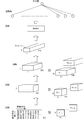
図2は、データの変換を説明するための図である。図2においては、音波信号Ssの一部がグラフ上に示されている。マイクロホン10aによって音波信号Ssが集音されると、A/D変換部10bは、制御部20に指示されたサンプリング周波数で音波信号をデジタル音波信号に変換する。図2において音波信号Ssに重ねられた黒丸はサンプリングされた振幅を示しており、その下部にサンプリング値が示されている。例えば、図2においては、最初のサンプリング値は10進数で0,次のサンプリング値は10進数で12である。教師データ30aにおいては、このようにして得られた時間軸上の複数の位置における値のセットに対して、音源の種類を示す情報(ラベル)が対応づけられている。
2 is a diagram for explaining data conversion. In FIG. 2, a part of the sound wave signal Ss is shown on the graph. When the sound wave signal Ss is collected by the microphone 10 a, the A/D conversion unit 10 b converts the sound wave signal into a digital sound wave signal at the sampling frequency instructed by the control unit 20. In FIG. 2, the black circles superimposed on the sound wave signal Ss indicate the sampled amplitude, and the sampling value is shown below it. For example, in FIG. 2, the first sampling value is 0 in decimal and the second sampling value is 12 in decimal. In the teacher data 30a, information (label) indicating the type of sound source is associated with the set of values at a plurality of positions on the time axis thus obtained.
本実施形態において、機械学習処理は、ニューラルネットワークを形成する訓練モデルを最適化する処理であり、本実施形態においては、図4に示すフローチャートに従って実行される。ここで、モデルとは、分類対象のデータと分類結果のデータとの対応関係を導出する式を示す情報であり、本実施形態において分類結果は、音楽であるか否かである。分類対象は音波信号から変換、出力された時系列データである。すなわち、本実施形態においては、機械学習のモデルに対して、A/D変換部10bされたデジタル音波信号(10進数表現)を直接入力するのではなく、デジタル音波信号を変換し、出力した時系列データを入力する。
In the present embodiment, the machine learning process is a process of optimizing a training model forming a neural network, and in the present embodiment, the machine learning process is executed according to the flowchart shown in FIG. Here, the model is information indicating an equation for deriving the correspondence between the classification target data and the classification result data, and in the present embodiment, the classification result is whether or not music. The classification target is the time-series data converted and output from the sound wave signal. That is, in the present embodiment, when a digital sound wave signal (decimal number expression) that has been A/D converted by the A/D conversion unit 10b is not directly input to the model of machine learning, but is converted and output. Enter the series data.
このように時系列データを利用した処理を行うために、制御部20は、信号取得部20a、変換部20b、出力部20cを備えている。信号取得部20aは、時間変化する信号であって、時間軸上の複数の位置における値のそれぞれが1個の成分で表現された信号を取得する機能を制御部20に実行させる。本実施形態において当該時間変化する信号は、音波信号を既定のサンプリング周波数でサンプリングして10進数の値で表現した信号であり、機械学習の際には教師データ30aが当該信号に相当する。すなわち、機械学習処理が開始されると、制御部20は、記憶媒体30を参照し、各教師データ30aから音波信号を取得する(ステップS100)。この結果、図2に示すように、音波信号の複数の時間軸上の位置における振幅を10進数で表現したデータセットが複数個得られる。
The control unit 20 includes a signal acquisition unit 20a, a conversion unit 20b, and an output unit 20c in order to perform processing using time-series data as described above. The signal acquisition unit 20a causes the control unit 20 to perform a function of acquiring a signal that is a time-varying signal and in which each of the values at a plurality of positions on the time axis is expressed by one component. In the present embodiment, the time-varying signal is a signal in which a sound wave signal is sampled at a predetermined sampling frequency and expressed as a decimal value, and in machine learning, the teacher data 30a corresponds to the signal. That is, when the machine learning process is started, the control unit 20 refers to the storage medium 30 and acquires a sound wave signal from each teacher data 30a (step S100). As a result, as shown in FIG. 2, a plurality of data sets in which the amplitudes of the sound wave signal at a plurality of positions on the time axis are expressed in decimal are obtained.
変換部20bは、複数の位置毎の値のそれぞれを、複数の成分の値で表現した多次元量に変換する機能を制御部20に実行させるプログラムモジュールである。すなわち、10進数による振幅の表現は、時間軸上のある位置における振幅の大きさを1個の成分で示しているため、制御部20は、より多数の成分によって音波信号を表現するため、音波信号を多次元量に変換する(ステップS105)。
The conversion unit 20b is a program module that causes the control unit 20 to execute a function of converting each value at each of a plurality of positions into a multidimensional amount expressed by a plurality of component values. That is, since the expression of the amplitude by the decimal number indicates the magnitude of the amplitude at a certain position on the time axis by one component, the control unit 20 expresses the sound wave signal by a larger number of components, and thus the sound wave is generated. The signal is converted into a multidimensional quantity (step S105).
多次元量への変換では、1個の成分での表現を複数個の成分での表現に変換することができればよく、本実施形態において制御部20は、時間軸上の各位置における振幅の大きさを2進数の値に変換する。すなわち、変換後の2進数の値の各桁が多次元量の成分となる。図2においては、音圧の振幅の大きさを示す値の下方に変換後の2進数の値(8ビット)を示している。この例では、上方から下方に向けて下位の桁から上位の桁が並ぶように表示してある。例えば、最初のサンプリング値である10進数の0は2進数で00000000、次のサンプリング値である10進数の12は2進数で00001100である。なお、実際のデジタル音波信号における時間長は、図2に示された時間長より長く、例えば、10kHzでサンプリングされた1秒分のデータ(10000個のデータ)等でデジタル音波信号が構成され、当該デジタル音波信号が変換対象となる。
In the conversion into a multidimensional quantity, it is sufficient that the expression with one component can be converted into the expression with a plurality of components. In the present embodiment, the control unit 20 determines the magnitude of the amplitude at each position on the time axis. Is converted to a binary value. That is, each digit of the converted binary number becomes a multidimensional component. In FIG. 2, the converted binary value (8 bits) is shown below the value indicating the amplitude of the sound pressure. In this example, the lower digits to the upper digits are displayed so as to be arranged from the upper side to the lower side. For example, the first sampled value of decimal 0 is binary number 00000000, and the second sampled value of decimal 12 is binary number 00001100. The time length of the actual digital sound wave signal is longer than the time length shown in FIG. 2, and for example, the digital sound wave signal is composed of 1 second of data (10000 pieces of data) sampled at 10 kHz. The digital sound wave signal is a conversion target.
出力部20cは、多次元量を、連続する複数の位置における多次元量の同一の成分の値を少なくとも含む時系列データとして出力する機能を制御部20に実行させるプログラムモジュールである。本実施形態においては、ステップS105で変換された2進数の値の桁を成分と見なしており、制御部20は、出力部20cの機能により、桁毎の値を抽出することで時系列データを出力する(ステップS110)。
The output unit 20c is a program module that causes the control unit 20 to execute a function of outputting a multidimensional amount as time-series data including at least values of the same component of the multidimensional amount at a plurality of consecutive positions. In the present embodiment, the digit of the binary value converted in step S105 is regarded as a component, and the control unit 20 extracts the value of each digit by the function of the output unit 20c to obtain the time series data. Output (step S110).
例えば、図2に示す例においては、2進数で表現された多次元量の最下位桁を一点鎖線で囲んで示している。制御部20は、当該最下位桁において時間軸上で異なる位置に存在する各値を、時間軸上の順序に従って並べたデータを、最下位桁成分の時系列データD1として生成する。このように、本実施形態において時系列データは、同一の成分の値の時間変化を示す1次元データである。1次元データは、多次元量の各成分について実施されてよい。すなわち、2進数の上位桁について時系列データが抽出された場合、当該時系列データはデジタル音波信号の振幅の大きい変化を示している。一方、2進数の下位桁について時系列データが抽出された場合、当該時系列データはデジタル音波信号の振幅の細かい変化を示している。
For example, in the example shown in FIG. 2, the least significant digit of the multidimensional amount represented by a binary number is surrounded by a dashed line. The control unit 20 generates data in which the respective values existing at different positions on the time axis in the least significant digit are arranged in the order on the time axis as the time series data D 1 of the least significant digit component. As described above, in the present embodiment, the time-series data is one-dimensional data indicating the time change of the value of the same component. One-dimensional data may be implemented for multi-dimensional quantities of each component. That is, when the time series data is extracted for the upper digit of the binary number, the time series data shows a large change in the amplitude of the digital sound wave signal. On the other hand, when the time series data is extracted for the lower digit of the binary number, the time series data indicates a fine change in the amplitude of the digital sound wave signal.
従って、機械学習の目的や分類対象に応じて、時系列データとして抽出すべき成分の数は、1以上、多次元量の成分の数以下の整数の中から選択されてよい。本実施形態においては、8桁の2進数の全成分(全桁)について時系列データが出力される。このため、図2においては、時系列データD1以外にも、時系列データD2~D8が出力されることが示されている。
Therefore, the number of components to be extracted as time-series data may be selected from an integer equal to or greater than 1 and equal to or less than the number of components of a multidimensional amount according to the purpose of machine learning or a classification target. In the present embodiment, time-series data is output for all 8-digit binary components (all digits). Therefore, FIG. 2 shows that the time series data D 2 to D 8 are output in addition to the time series data D 1 .
本実施形態においては、以上のようにして出力された時系列データに基づいて音の分類を行う。すなわち、時系列データを入力するモデルを機械学習によって最適化する機械学習処理を行う。機械学習は、種々の手法で行われて良いが、本実施形態においては、畳み込みニューラルネットワーク(CNN:Convolutional Neural Network)と再帰ニューラルネットワーク(RNN:Recurrent Neural Network)とを含むニューラルネットワークによって機械学習が行われる例を説明する。
In the present embodiment, the sound is classified based on the time series data output as described above. That is, a machine learning process for optimizing a model for inputting time series data by machine learning is performed. Machine learning may be performed by various methods, but in the present embodiment, machine learning is performed by a neural network including a convolutional neural network (CNN: Convolutional Neural Network) and a recurrent neural network (RNN: Recurrent Neural Network). An example will be described.
図3は、図2に示す例に適用可能なモデルの一例を示す図である。図3においては、下部から上方に向けて演算が進行するようにモデルが記載されている。図3に示す例において、初期の3層はCNNによって構成されている。また、図3に示す例において、CNNによる出力結果はRNNに入力され、RNNによる出力は全結合を経て出力層に至る。
3 is a diagram showing an example of a model applicable to the example shown in FIG. In FIG. 3, the model is described so that the calculation proceeds from the lower part to the upper part. In the example shown in FIG. 3, the initial three layers are composed of CNN. Further, in the example shown in FIG. 3, the output result by CNN is input to RNN, and the output by RNN reaches the output layer through full coupling.
図3の最下部には入力データとなる8チャンネル分の時系列データD1~D8が例示されている。ここでは、時間軸上の位置が10000個、すなわち、10kHzで10000回サンプリングされることによって得られたデジタル音波信号が変換され、時系列データとして出力された例を示している。本実施形態においては、時系列データD1~D8の時間方向の情報を畳み込む演算が行われる。
At the bottom of FIG. 3, time-series data D 1 to D 8 for 8 channels which are input data are illustrated. Here, an example is shown in which digital sound wave signals obtained by sampling 10,000 positions on the time axis, that is, 10,000 times at 10 kHz are converted and output as time-series data. In the present embodiment, a calculation for convoluting the time-series data D 1 to D 8 in the time direction is performed.
すなわち、時系列データD1~D8のそれぞれは1次元の時系列データであり、合計で8チャンネルである。そこで、本実施形態においては、2次元(時間軸方向とチャンネル方向)のフィルタが用意され、畳み込み演算が行われる。図3に示す例において、フィルタは2次元であり、30×8個の値(時間軸上で連続する30個の位置の値が8チャンネル分存在する)を畳み込むフィルタである。図3においては、当該フィルタの大きさが1×30×8として示されている。むろん、フィルタの大きさは30に限定されず、例えば50、40、20または10でもよいし、これら例示した数値の何れか2つの間の範囲であってもよい。フィルタの大きさが短い方が信号を取得後の処理を早く始めることができる。また図3では入力データを8チャンネルとしているがこれも8に限定されない。フィルタの数も限定されないが、図3に示す例においてCNNの最初の層でのフィルタ数は128個である。図3においては、これらのフィルタがF1-1~F1-128として示されている。本実施形態においては、このように時間軸方向の大きさが短いフィルタを用いることができるので、従来技術に比べて時系列データの微細な変化を捉えることができる。従来技術では、時間変化する波形信号の振幅をサンプリングして10進数の値で表現した場合、時間軸方向の大きさが短いフィルタでは微細な振幅の変化や大局的な振幅の時間変化を直接的に捉えることは困難である。フーリエ変換等では、時間空間で短期間の信号を利用すると周波数空間の情報の精度が低下してしまう。すなわち信号を取得してから特徴を出力するまでにより時間が必要となる。
That is, each of the time series data D 1 to D 8 is one-dimensional time series data and has a total of 8 channels. Therefore, in the present embodiment, a two-dimensional (time axis direction and channel direction) filter is prepared and the convolution operation is performed. In the example shown in FIG. 3, the filter is two-dimensional, and is a filter that convolves 30×8 values (values of 30 consecutive positions on the time axis for 8 channels). In FIG. 3, the size of the filter is shown as 1×30×8. Of course, the size of the filter is not limited to 30, and may be, for example, 50, 40, 20 or 10, or may be in a range between any two of these exemplified numerical values. The shorter the filter size, the earlier the processing after signal acquisition can be started. Further, in FIG. 3, the input data is eight channels, but it is not limited to eight. Although the number of filters is not limited, the number of filters in the first layer of CNN is 128 in the example shown in FIG. In FIG. 3, these filters are shown as F 1-1 to F 1-128 . In the present embodiment, since a filter having a short size in the time axis direction can be used as described above, it is possible to capture a minute change in time series data as compared with the conventional technique. In the prior art, when the amplitude of a time-varying waveform signal is sampled and expressed as a decimal value, a filter having a short size in the time axis direction directly causes a minute amplitude change or a global amplitude time change. Is difficult to capture. In the Fourier transform or the like, if a short-term signal is used in the time space, the accuracy of the information in the frequency space will decrease. That is, more time is required from the acquisition of the signal to the output of the feature.
各フィルタは、既定のパディングやストライドで時系列データD1~D8のそれぞれに適用される。例えば、ストライド10で適宜パディングを行えば10000個のデータは1000個になる。これらを足し合わせることによって1個のフィルタによる出力結果が得られる。従って、フィルタ数が128個の場合、1000個のデータを有する1次元のデータが128個生成される。図3においては、当該1×1000×128のデータが長方形によって示されている。むろん、ストライドやパディング等のハイパーパラメータは一例であり、出力されるデータの数(1000個等)等も一例である(他の層も同様)。
Each filter is applied to each of the time series data D 1 to D 8 with a predetermined padding or stride. For example, if the stride 10 is appropriately padded, the 10,000 data will be 1,000. The output result of one filter is obtained by adding these. Therefore, when the number of filters is 128, 128 one-dimensional data having 1000 data are generated. In FIG. 3, the 1×1000×128 data is indicated by a rectangle. Of course, hyperparameters such as stride and padding are examples, and the number of output data (1000 pieces, etc.) is also an example (same for other layers).
いずれにしてもCNNの最初の層による演算によって1×1000×128のデータが出力されると、このデータは次のCNNの層への入力データとなる。図3においては、第2層で1×30×128の大きさのフィルタが256個用意され、さらに第3層で1×30×256の大きさのフィルタが512個用意される例が示されている。ストライドやパディングは最初の層と同様である。この例であれば、以上の3層の演算により、1×10×512個のデータDCNNが出力される。
In any case, when 1×1000×128 data is output by the calculation by the first layer of CNN, this data becomes the input data to the next layer of CNN. FIG. 3 shows an example in which 256 filters of size 1×30×128 are prepared in the second layer, and 512 filters of size 1×30×256 are further prepared in the third layer. ing. Stride and padding are similar to the first layer. In this example, 1×10×512 pieces of data D CNN are output by the above-described calculation of the three layers.
当該データDCNNは、RNNへの入力になる。図3に示すRNNを構成する要素はLSTM(Long Short-Term Memory)であるが、要素はGRU(Gated Recurrent Unit)であってもよいし、双方向のモデルが採用されてもよく、種々の構成を採用可能である。むろん、ハイパーパラメータは種々のパラメータとして良い。
The data D CNN becomes an input to the RNN. Although the element forming the RNN shown in FIG. 3 is an LSTM (Long Short-Term Memory), the element may be a GRU (Gated Recurrent Unit) or a bidirectional model may be adopted. A configuration can be adopted. Of course, the hyperparameter may be various parameters.
いずれにしても、図3に示す例においては、RNNに入力されるデータDCNNが1×10×512個のデータであるため、この例ではLSTMに対して512個のデータを10回入力する演算が行われる。図3においては、最初に入力される512個の入力値をX1-1~X1-512、次に入力される512個の入力値をX2-1~X2-512などのようにして示している。
In any case, in the example shown in FIG. 3, since the data D CNN input to the RNN is 1×10×512 data, 512 data are input 10 times to the LSTM in this example. Calculation is performed. In FIG. 3, the first 512 input values are input as X 1-1 to X 1-512 , the next 512 input values are input as X 2-1 to X 2-512 , and so on. Is shown.
さらに、図3に示すLSTMではLSTMからの出力が1024個である例が想定されており、最後のLSTMから出力されるデータY1~Y1024が次の層に入力される。すなわち、データY1~Y1024が全結合層に入力され、全結合層の次の層で音楽であるか否かの分類結果を出力する。
Furthermore, in the LSTM shown in FIG. 3, it is assumed that the LSTM outputs 1024, and the data Y 1 to Y 1024 output from the last LSTM are input to the next layer. That is, the data Y 1 to Y 1024 are input to the fully connected layer, and the classification result indicating whether or not the layer is the music next to the fully connected layer is output.
本実施形態において制御部20は、機械学習部20dの機能により、以上のようなモデルに基づいて機械学習処理を実行する。すなわち、制御部20は、機械学習部20dの機能により、時系列データを入力し、信号の音源の特徴に関する情報を出力する機械学習済モデルを機械学習する。具体的には、制御部20は、機械学習部20dの機能により、訓練モデルを取得する(ステップS115)。すなわち、図3に示すようなニューラルネットワークの構造に対応した各種の情報(モデルを示すフィルタや活性化関数等の情報)が予め定義されており、制御部20は、当該情報を取得することで訓練モデルを取得する。
In the present embodiment, the control unit 20 executes the machine learning process based on the above model by the function of the machine learning unit 20d. That is, the control unit 20 machine-learns a machine-learned model that receives time-series data and outputs information related to the characteristics of the sound source of the signal by the function of the machine learning unit 20d. Specifically, the control unit 20 acquires the training model by the function of the machine learning unit 20d (step S115). That is, various kinds of information corresponding to the structure of the neural network as shown in FIG. 3 (information such as a filter indicating a model and an activation function) is defined in advance, and the control unit 20 acquires the information. Get the training model.
次に、制御部20は、機械学習部20dの機能により、教師データ30aのラベルを取得する(ステップS120)。すなわち、制御部20は、ステップS100で取得した各音波信号の音源の種類を示すラベルを取得する。例えば、図3に示す例であれば、ラベルは出力層のノードの出力値が1,0のいずれであるかを示しており、ステップS100で取得された音波信号の音源が音楽である場合に1,音楽以外の音である場合に0が取得される。
Next, the control unit 20 acquires the label of the teacher data 30a by the function of the machine learning unit 20d (step S120). That is, the control unit 20 acquires the label indicating the type of the sound source of each sound wave signal acquired in step S100. For example, in the example shown in FIG. 3, the label indicates whether the output value of the node in the output layer is 1, 0, and when the sound source of the sound wave signal acquired in step S100 is music. 1, 0 is acquired when it is a sound other than music.
次に、制御部20は、機械学習部20dの機能により、テストデータを取得する(ステップS125)。本実施形態において制御部20は、ステップS110で取得されたデータの一部を抽出し、ステップS120で取得されたラベルを対応づけてテストデータとする。テストデータは、学習の汎化が行われたか否かを確認するためのデータであり、機械学習には使用されない。
Next, the control unit 20 acquires test data by the function of the machine learning unit 20d (step S125). In the present embodiment, the control unit 20 extracts a part of the data acquired in step S110, and associates the label acquired in step S120 with it to make it test data. The test data is data for confirming whether or not learning generalization has been performed, and is not used for machine learning.
次に、制御部20は、機械学習部20dの機能により、初期値を決定する(ステップS130)。すなわち、制御部20は、ステップS115で取得した訓練モデルのうち、学習対象となる可変のパラメーター(フィルタの重みやバイアス等)に対して初期値を与える。初期値は、種々の手法で決定されて良い。むろん、学習の過程でパラメータが最適化されるように初期値が調整されても良いし、各種のデータベース等から学習済のパラメータが取得されて利用されても良い。
Next, the control unit 20 determines the initial value by the function of the machine learning unit 20d (step S130). That is, the control unit 20 gives initial values to the variable parameters (filter weight, bias, etc.) to be learned in the training model acquired in step S115. The initial value may be determined by various methods. Of course, the initial values may be adjusted so that the parameters are optimized during the learning process, or the learned parameters may be acquired from various databases and used.
次に、制御部20は、機械学習部20dの機能により、学習を行う(ステップS135)。すなわち、制御部20は、ステップS115で取得した訓練モデルにステップS110で出力された時系列データを入力し、分類結果を示す情報を出力する。分類結果を示す情報が出力されると、制御部20は、当該出力と、ステップS120で取得されたラベルとの誤差を示す損失関数によって誤差を特定する。損失関数が得られたら、制御部20は、既定の最適化アルゴリズム、例えば、確率的勾配降下法等によってパラメータを更新する。すなわち、制御部20は、損失関数のパラメータによる微分に基づいてパラメータを更新する処理を既定回数繰り返す。
Next, the control unit 20 performs learning by the function of the machine learning unit 20d (step S135). That is, the control unit 20 inputs the time-series data output in step S110 to the training model acquired in step S115, and outputs information indicating the classification result. When the information indicating the classification result is output, the control unit 20 specifies the error by the loss function indicating the error between the output and the label acquired in step S120. When the loss function is obtained, the control unit 20 updates the parameter by a predetermined optimization algorithm, for example, the stochastic gradient descent method. That is, the control unit 20 repeats the process of updating the parameter based on the differentiation of the loss function by the parameter for a predetermined number of times.
以上のようにして、既定回数のパラメータの更新が行われると、制御部20は、訓練モデルの汎化が完了したか否かを判定する(ステップS140)。すなわち、制御部20は、ステップS125で取得したテストデータを訓練モデルに入力して音波信号の分類結果を出力する。そして、制御部20は、出力された分類結果と、テストデータに対応づけられた分類結果とが一致している数(分類結果とラベルとの誤差が既定値以下である数)を取得し、サンプル数で除することで分類精度を取得する。本実施形態において、制御部20は、分類精度が閾値以上である場合に汎化が完了したと判定する。
When the parameters have been updated the predetermined number of times as described above, the control unit 20 determines whether or not the generalization of the training model has been completed (step S140). That is, the control unit 20 inputs the test data acquired in step S125 into the training model and outputs the sound wave signal classification result. Then, the control unit 20 obtains the number of coincidences between the output classification result and the classification result associated with the test data (the number of errors between the classification result and the label is equal to or less than the default value), The classification accuracy is obtained by dividing by the number of samples. In the present embodiment, the control unit 20 determines that the generalization is completed when the classification accuracy is equal to or higher than the threshold value.
なお、汎化性能の評価に加え、ハイパーパラメータの妥当性の検証が行われてもよい。すなわち、学習対象となる可変のパラメータ以外の可変量であるハイパーパラメータ、例えば、フィルタサイズやノードの数等がチューニングされる構成において、制御部20は、検証データに基づいてハイパーパラメータの妥当性を検証しても良い。検証データは、ステップS125と同様の処理により、検証データを予め抽出し、訓練に用いないデータとして確保しておくことで取得すれば良い。
-In addition to the evaluation of generalization performance, the validity of hyperparameters may be verified. That is, in a configuration in which a hyperparameter that is a variable amount other than the variable parameter to be learned, such as the filter size and the number of nodes, is tuned, the control unit 20 determines the validity of the hyperparameter based on the verification data. You may verify. The verification data may be acquired by preliminarily extracting the verification data by the same process as in step S125 and securing it as data not used for training.
ステップS140において、訓練モデルの汎化が完了したと判定されない場合、制御部20は、ステップS135を繰り返す。すなわち、さらに学習対象となる可変のパラメータを更新する処理を行う。一方、ステップS140において、訓練モデルの汎化が完了したと判定された場合、制御部20は、機械学習済モデルを記録する(ステップS145)。すなわち、制御部20は、訓練モデルを機械学習済モデル30bとして記憶媒体30に記録する。
If it is not determined in step S140 that the generalization of the training model is completed, the control unit 20 repeats step S135. That is, the process of further updating the variable parameter to be learned is performed. On the other hand, when it is determined in step S140 that the generalization of the training model is completed, the control unit 20 records the machine-learned model (step S145). That is, the control unit 20 records the training model in the storage medium 30 as the machine-learned model 30b.
(1-2)特徴出力処理:
次に、音源の種類を分類する特徴出力処理を図5に示すフローチャートに基づいて説明する。コンピュータ10の周辺で分類対象の音源から音が出力されている状態で、コンピュータ10の利用者は、キーボードやマウスなどの図示しない入力部を操作して特徴出力処理の実行開始指示を行う。利用者が当該実行開始指示を行うと、制御部20は、特徴出力処理の実行を開始する。 (1-2) Feature output processing:
Next, the characteristic output processing for classifying the types of sound sources will be described based on the flowchart shown in FIG. While sound is being output from the sound source to be classified in the vicinity of thecomputer 10, the user of the computer 10 operates an input unit (not shown) such as a keyboard and a mouse to give an instruction to start execution of the characteristic output process. When the user gives the execution start instruction, the control unit 20 starts execution of the characteristic output process.
次に、音源の種類を分類する特徴出力処理を図5に示すフローチャートに基づいて説明する。コンピュータ10の周辺で分類対象の音源から音が出力されている状態で、コンピュータ10の利用者は、キーボードやマウスなどの図示しない入力部を操作して特徴出力処理の実行開始指示を行う。利用者が当該実行開始指示を行うと、制御部20は、特徴出力処理の実行を開始する。 (1-2) Feature output processing:
Next, the characteristic output processing for classifying the types of sound sources will be described based on the flowchart shown in FIG. While sound is being output from the sound source to be classified in the vicinity of the
特徴出力処理の実行が開始されると、制御部20は、音波信号を取得する(ステップS200)。すなわち、音源から音波が出力されると、マイクロホン10aは当該音波を取得してアナログ音波信号を出力する。制御部20は機械学習の際に使用されたサンプリング周波数と同一のサンプリング周波数を予めA/D変換部10bに指示している。A/D変換部10bは当該サンプリング周波数でアナログ音波信号をサンプリングし、デジタル音波信号に変換する。そして、A/D変換部10bからデジタル音波信号が出力されると、制御部20は、信号取得部20aの機能により、当該デジタル音波信号を取得する。例えば、図2に示す音波信号Ssであれば、A/D変換部10bによって10進数のデジタル音波信号(0,12,6,,,,)が出力されるため、制御部20は、当該デジタル音波信号を取得する。
When the execution of the characteristic output process is started, the control unit 20 acquires a sound wave signal (step S200). That is, when a sound wave is output from the sound source, the microphone 10a acquires the sound wave and outputs an analog sound wave signal. The control unit 20 preliminarily instructs the A/D conversion unit 10b to have the same sampling frequency as that used for machine learning. The A/D converter 10b samples the analog sound wave signal at the sampling frequency and converts it into a digital sound wave signal. Then, when the digital sound wave signal is output from the A/D conversion unit 10b, the control unit 20 acquires the digital sound wave signal by the function of the signal acquisition unit 20a. For example, in the case of the sound wave signal Ss shown in FIG. 2, since the A/D conversion unit 10b outputs a decimal sound wave signal (0, 12, 6,,... ), the control unit 20 controls the digital sound signal Ss. Acquire sound wave signals.
次に、制御部20は、A/D変換部10bの機能により、音波信号を多次元量に変換する(ステップS205)。すなわち、制御部20は、ステップS200で取得されたデジタル音波信号を取得し、時間軸上の複数の位置のそれぞれの振幅を示す10進数の値を2進数に変換する。例えば、ステップS200において、図2に示すデジタル音波信号(0,12,6,,,,)が取得された場合、図2に示す2進数の多次元量(00000000,00001100,,,,)が取得される。
Next, the control unit 20 converts the sound wave signal into a multidimensional amount by the function of the A/D conversion unit 10b (step S205). That is, the control unit 20 acquires the digital sound wave signal acquired in step S200, and converts the decimal value indicating the amplitude of each of a plurality of positions on the time axis into a binary number. For example, in step S200, when the digital sound wave signals (0, 12, 6,,,) shown in FIG. 2 are acquired, the binary multidimensional quantity (000000000001100,,,) shown in FIG. 2 is obtained. To be acquired.
次に、制御部20は、出力部20cの機能により、時系列データを出力する(ステップS210)。すなわち、制御部20は、多次元量の桁毎の値を抽出し、各桁の時系列データを生成する。例えば、図2に示す例であれば、制御部20は、時系列データD1~D8を取得する。
Next, the control unit 20 outputs the time series data by the function of the output unit 20c (step S210). That is, the control unit 20 extracts a value for each digit of the multidimensional amount and generates time-series data of each digit. For example, in the example shown in FIG. 2, the control unit 20 acquires the time series data D 1 to D 8 .
次に、制御部20は、特徴出力部20eの機能により、音の特徴を判定する(ステップS215)。すなわち、制御部20は、機械学習済モデル30bを取得し、ステップS210で出力された時系列データD1~D8を当該機械学習済モデル30bに対して入力する。制御部20は、当該機械学習済モデル30bが示すパラメータを利用して図3に示すCNN,RNN等の演算を行う。この結果、出力層の値が決定される。なお、図2,図3に示す例においては、8チャンネルの1次元データである時系列データD1~D8を機械学習済モデル30bに入力しているが、チャンネル数は8に限定されず、1以上、多次元量の成分の数以下の整数であって良い。
Next, the control unit 20 determines the feature of the sound by the function of the feature output unit 20e (step S215). That is, the control unit 20 acquires the machine-learned model 30b and inputs the time-series data D 1 to D 8 output in step S210 to the machine-learned model 30b. The control unit 20 uses the parameters indicated by the machine-learned model 30b to calculate CNN, RNN, etc. shown in FIG. As a result, the value of the output layer is determined. In the examples shown in FIGS. 2 and 3, the time-series data D 1 to D 8 which are eight- dimensional one-dimensional data are input to the machine-learned model 30b, but the number of channels is not limited to eight. It may be an integer greater than or equal to 1 and less than or equal to the number of multidimensional components.
制御部20は、出力層の値と閾値とを比較し、閾値以上であれば音源の種類が音楽であると判定し、閾値より小さければ音源の種類が音楽ではないと判定する。例えば、出力層の値が0~1の範囲で変化し、閾値が0.9である場合、出力層の値が0.9以上であれば、制御部20は、音源の種類が音楽であると見なす。
The control unit 20 compares the value of the output layer with the threshold value, and determines that the sound source type is music if the threshold value or more, and determines that the sound source type is not music if it is smaller than the threshold value. For example, when the value of the output layer changes in the range of 0 to 1 and the threshold value is 0.9 and the value of the output layer is 0.9 or more, the control unit 20 determines that the sound source type is music. To consider.
次に、制御部20は、特徴出力部20eの機能により、判定結果を出力する(ステップS220)。すなわち、制御部20は、表示部40を制御して、音源の種類を示す情報を表示させる。以上の構成においては、10進数の数値で表現された振幅をより多数の成分の値で表現した多次元量に変換して機械学習した結果に基づいて音の特徴を判定することができる。従って、10進数で表現された元の信号よりも多様な特徴を捉えた機械学習を行って音の特徴を判定することができ、高精度に音の特徴を判定することができる。
Next, the control unit 20 outputs the determination result by the function of the feature output unit 20e (step S220). That is, the control unit 20 controls the display unit 40 to display information indicating the type of sound source. With the above configuration, the characteristic of the sound can be determined based on the result of machine learning by converting the amplitude represented by the decimal number into the multidimensional amount represented by the value of a larger number of components. Therefore, it is possible to determine the characteristics of the sound by performing machine learning that captures more various characteristics than the original signal represented by a decimal number, and it is possible to determine the characteristics of the sound with high accuracy.
さらに、本実施形態においては、多次元量を、同一成分(同一桁毎)毎に分解し、同一成分の値の時間変化を示す時系列データを用いて機械学習および特徴の取得を行う。この結果、大局的な時間変化と微細な時間変化の双方を含んだ音波信号の時間変化を詳細に捉えることができる。従って、10進数で表現された元の信号よりも多様な時間変化を捉えた機械学習を行って音の特徴を判定することができ、高精度に音の特徴を判定することができる。なお、微細な時間変化がノイズであり、微細な時間変化を除いた部分に信号の特徴が現れる場合には、微細な時間変化が分類に与える重みが小さくなるように学習される。従って、ノイズが含まれていても高精度に音の特徴を判定することができる。
Further, in the present embodiment, the multidimensional amount is decomposed for each same component (each same digit), and machine learning and feature acquisition are performed using time-series data showing a time change of the value of the same component. As a result, the time change of the sound wave signal including both the global time change and the minute time change can be captured in detail. Therefore, it is possible to determine the characteristics of the sound by performing machine learning that captures various temporal changes more than the original signal represented by a decimal number, and it is possible to determine the characteristics of the sound with high accuracy. When the minute time change is noise and the signal features appear in the portion excluding the minute time change, learning is performed so that the weight given to the classification by the minute time change becomes small. Therefore, the characteristics of the sound can be determined with high accuracy even if noise is included.
ここで、本実施形態を用いて環境音イベント分類を行った場合と、公知の手法を用いて環境音イベント分類を行った場合とにおける分類精度を比較する。環境音は、参考文献のTable 2に記載された28種類のイベントを含むデータベースを利用した。このデータベースに基づいて、参考文献に記載されたようにパワースペクトル(256次元)とその変化量Δ、ΔΔの3チャンネルを分類モデルに入力し、環境音イベントを分類する例を対比例とする。なお、この場合の分類モデルは、6層のCNNを通した結果を3層の全結合層に通すモデルである。当該分類モデルで機械学習を行った場合の分類精度は、80.3%であった。
Here, the classification accuracy is compared between the case where environmental sound event classification is performed using this embodiment and the case where environmental sound event classification is performed using a known method. For environmental sounds, we used a database containing 28 types of events listed in Table 2 of the reference. Based on this database, as described in the reference document, three channels of the power spectrum (256 dimensions) and their variations Δ and ΔΔ are input to the classification model, and an example of classifying the environmental sound event is made proportional. The classification model in this case is a model in which the result of passing through 6 layers of CNN is passed through through 3 layers of fully connected layers. The classification accuracy when machine learning was performed using the classification model was 80.3%.
一方、このデータベースに基づいて、本実施形態の図3に基づいて機械学習を行った場合、分類精度は88.3%であった。このように、本実施形態によれば、公知の手法と比較して分類精度が大幅に改善している。(参考文献)N. Takahashi, et al., "Deep Convolutional Neural Networks and Data Augmentation for Acoustic Event Detection," Proc. of INTERSPEECH2016, pp.2982-2986, 2016
On the other hand, when machine learning was performed based on this database based on FIG. 3 of the present embodiment, the classification accuracy was 88.3%. As described above, according to this embodiment, the classification accuracy is significantly improved as compared with the known method. (Reference) N.Takahashi, et al., "Deep Convolutional Neural Networks and Data Augmentation for Acoustic Event Detection," Proc. of INTERSPEECH2016, pp.2982-2986, 2016
(2)他の実施形態:
以上の実施形態は本発明を実施するための一例であり、時間変化する信号の時間軸上の各位置における値を多次元量で表現し、多次元量の成分毎の時間変化を示す時系列データを出力する限りにおいて、他にも種々の実施形態を採用可能である。例えば、1台のコンピュータ10によって、信号変換システム、機械学習システム、特徴出力システムが構成されていたが、それぞれが別のシステムであっても良いし、2個のシステムが1台のシステムとして構成されてもよい。 (2) Other embodiments:
The above embodiment is an example for carrying out the present invention, in which the value at each position on the time axis of a signal that changes with time is represented by a multidimensional amount, and a time series indicating the time change for each component of the multidimensional amount. Various other embodiments can be adopted as long as data is output. For example, although the signal conversion system, the machine learning system, and the feature output system are configured by onecomputer 10, they may be different systems, or two systems are configured as one system. May be done.
以上の実施形態は本発明を実施するための一例であり、時間変化する信号の時間軸上の各位置における値を多次元量で表現し、多次元量の成分毎の時間変化を示す時系列データを出力する限りにおいて、他にも種々の実施形態を採用可能である。例えば、1台のコンピュータ10によって、信号変換システム、機械学習システム、特徴出力システムが構成されていたが、それぞれが別のシステムであっても良いし、2個のシステムが1台のシステムとして構成されてもよい。 (2) Other embodiments:
The above embodiment is an example for carrying out the present invention, in which the value at each position on the time axis of a signal that changes with time is represented by a multidimensional amount, and a time series indicating the time change for each component of the multidimensional amount. Various other embodiments can be adopted as long as data is output. For example, although the signal conversion system, the machine learning system, and the feature output system are configured by one
むろん、別個のシステムの連携法は種々の手法であって良く、クライアントとサーバとして構成されていても良い。さらに、信号取得部20a,変換部20b,出力部20c,機械学習部20d,特徴出力部20eの少なくとも一部が複数の装置に分かれて存在してもよい。例えば、信号取得部20aによって教師データ30aが取得される処理と、分類対象のデジタル音波信号が取得される処理とが異なる装置で実施される構成等であっても良い。むろん、上述の実施形態の一部の構成が省略されてもよいし、処理の順序が変動または省略されてもよい。
Needless to say, the method of linking separate systems may be various methods, and may be configured as a client and a server. Furthermore, at least a part of the signal acquisition unit 20a, the conversion unit 20b, the output unit 20c, the machine learning unit 20d, and the feature output unit 20e may be present separately in a plurality of devices. For example, the configuration may be such that the process of acquiring the teacher data 30a by the signal acquisition unit 20a and the process of acquiring the classification target digital sound wave signal are performed by different devices. Of course, a part of the configuration of the above-described embodiment may be omitted, or the order of processing may be changed or omitted.
例えば、上述の実施形態に示す機械学習のモデルによる処理過程で得られる情報が出力されるシステムが構成されても良い。具体的には、図3に示すモデルの過程でCNNのデータDCNNが得られるが、当該データDCNNが音の特徴を示す情報であるとして出力されても良い。当該情報は、音の特徴を示しているため、例えば、特定の音の種類の場合におけるデータDCNNのパターンを予め特定しておけば、音の種類の分類を行うことが可能である。むろん、機械学習を行うモデルは図3に示す例に限定されず、例えば、RNNが省略され、CNNのデータDCNNが全結合層に入力され、その後の層で分類結果を示す情報が出力される構成等であっても良い。
For example, a system may be configured in which the information obtained in the process of processing by the machine learning model shown in the above embodiment is output. Specifically, the data D CNN of CNN is obtained in the course of the model shown in FIG. 3, the data D CNN may be output as the information indicating the characteristics of the sound. Since the information indicates the feature of the sound, if the pattern of the data D CNN in the case of the specific sound type is specified in advance, the sound type can be classified. Of course, the model for machine learning is not limited to the example shown in FIG. 3. For example, the RNN is omitted, the CNN data D CNN is input to the fully connected layer, and the information indicating the classification result is output in the subsequent layers. It may be configured to be.
機械学習の態様は限定されず、例えばニューラルネットワークによる機械学習が行われる場合、モデルを構成する層の数やノードの数、活性化関数の種類、損失関数の種類、勾配降下法の種類、勾配降下法の最適化アルゴリズムの種類、ミニバッチ学習の有無やバッチの数、学習率、初期値、過学習抑制手法の種類や有無、畳み込み層の有無、畳み込み演算におけるフィルタのサイズ、フィルタの種類、パディングやストライドの種類、プーリング層の種類や有無、全結合層の有無、再帰的な構造の有無など、種々の要素を適宜選択して機械学習が行われればよい。むろん、他の機械学習、例えば、深層学習(ディープラーニング)、サポートベクターマシンやクラスタリング、強化学習等によって学習が行われてもよい。さらに、モデルの構造(例えば、層の数や層毎のノードの数等)が自動的に最適化される機械学習が行われてもよい。
The mode of machine learning is not limited. For example, when machine learning is performed by a neural network, the number of layers and nodes in the model, the type of activation function, the type of loss function, the type of gradient descent method, the gradient Type of optimization algorithm for descent method, presence/absence of mini-batch learning, number of batches, learning rate, initial value, type of presence/absence of overlearning suppression method, presence/absence of convolutional layer, filter size in convolution operation, filter type, padding Machine learning may be performed by appropriately selecting various elements such as the type of a stride, the type of stride, the presence or absence of a pooling layer, the presence or absence of a fully connected layer, and the presence or absence of a recursive structure. Of course, learning may be performed by other machine learning, for example, deep learning, support vector machine, clustering, reinforcement learning, or the like. Furthermore, machine learning may be performed in which the structure of the model (for example, the number of layers or the number of nodes for each layer) is automatically optimized.
分類態様は音楽と非音楽に限定されず、音楽と音声の分類であってもよいし、より多くの種類の音源の分類であっても良い。むろん、信号変換システムや機械学習システム、特徴出力システムの用途は、音源の種類の分類に限定されない。例えば、打音検査などの異常音検出に利用されても良いし、音楽の詳細分類(ジャンル分類や楽曲名分類等)に利用されても良いし、音声認識に利用されても良いし、音が関連するイベントの分類(環境音の種類の分類)に利用されても良い。利用場面も限定されず、例えば、放送音声に対する分類等が行われることによって放送内容の統計管理に利用されても良い。また、本発明は音源の分離に対しても適用できる。例えば音楽に対し音声が重畳された音源をニューラルネットワークに入力し音楽のみまたは音声のみを分離する技術が知られているが、本発明の時系列データをニューラルネットワークへ入力することにより、信号の時間変化の特徴を捉えやすくなるので、高精度・高効率な分離を実現できる。
The classification mode is not limited to music and non-music, and may be classification of music and voice, or classification of more kinds of sound sources. Of course, the uses of the signal conversion system, the machine learning system, and the feature output system are not limited to the classification of sound source types. For example, it may be used for abnormal sound detection such as tap sound inspection, may be used for detailed classification of music (genre classification, song name classification, etc.), may be used for voice recognition, and may be used for sound recognition. May be used to classify related events (classification of types of environmental sounds). The use scene is not limited, and may be used for statistical management of broadcast contents by, for example, classifying broadcast audio. The present invention can also be applied to sound source separation. For example, a technique is known in which a sound source in which voice is superimposed on music is input to a neural network to separate only music or only voice. However, by inputting the time-series data of the present invention to the neural network, the time of the signal is Since the characteristics of changes can be easily captured, highly accurate and highly efficient separation can be realized.
信号取得部は、時間変化する信号であって、時間軸上の複数の位置における値のそれぞれが1個の成分で表現された信号を取得することができればよい。すなわち、信号取得部は、時間軸上の各位置における値を単一成分で表現した信号を取得する。成分は、信号の特徴を示しており、成分が1個であれば信号を1個の特徴で表現することになる。従って、上述の実施形態のように、音波信号の振幅を一定期間毎にサンプリングし、時間軸上の1箇所について値が1個(スカラー量)であるような信号は、1個の成分で表現された信号である。また、1個の成分で表現された信号としては他にも種々の態様が採用され得る。
The signal acquisition unit should be able to acquire a signal that is a time-varying signal and in which each of the values at a plurality of positions on the time axis is represented by one component. That is, the signal acquisition unit acquires a signal in which the value at each position on the time axis is represented by a single component. The component indicates the feature of the signal, and if the component is one, the signal is represented by one feature. Therefore, as in the above-described embodiment, the amplitude of the sound wave signal is sampled at regular intervals, and a signal having one value (scalar amount) at one location on the time axis is represented by one component. It is a signal that has been processed. In addition, other various modes can be adopted as the signal represented by one component.
また、時間変化する信号は、時間軸上の異なる位置における値が異なり得る信号であれば良く、音波に限定されない。例えば、超音波や脳波、心電図、筋電図などの生体信号や、温度や湿度、気圧といった環境信号などの任意の波は、時間変化する信号になり得る。さらに、株価や為替チャートなどのように、着目している対象が時間変化する場合、対象の時間変化を示す情報は時間変化する信号に該当し得る。さらに、動画等の画像信号などにも適応が可能である。動画の画像信号においては、複数枚の画像の時系列の変化によって動画が表現される。そして、各画像においては、カラー画像の場合に赤・緑・青等の3チャンネルで1画素の色が表現され、グレー画像の場合に1チャンネルで1画素の輝度が表現され、各チャンネルのそれぞれが階調値を持つ(通常は0~255の値)。したがって、これらの画素の階調値を多次元量に変換し、変換後の成分毎の値を示す時系列データを出力する構成を採用することもできる。むろん、本発明の一実施形態で出力された特徴は、分類や認識以外にも種々の目的で利用されて良く、例えば、未来の信号変化の予測等に利用されても良い。以上のように、時間変化する信号の特徴が音源の種類である構成に限定されず、信号における種々の特徴が特徴出力部によって出力されて良い。
Also, the time-varying signal is not limited to a sound wave, as long as the signal can have different values at different positions on the time axis. For example, a biological signal such as an ultrasonic wave, an electroencephalogram, an electrocardiogram, an electromyogram, or an arbitrary wave such as an environmental signal such as temperature, humidity, or atmospheric pressure can be a time-varying signal. Furthermore, when a target of interest changes over time, such as a stock price or an exchange chart, the information indicating the change over time of the target may correspond to a signal that changes over time. Furthermore, it is possible to adapt to image signals such as moving images. In the image signal of the moving image, the moving image is represented by the time-series change of a plurality of images. In each image, in the case of a color image, the color of one pixel is expressed by three channels such as red, green, and blue, and in the case of a gray image, the brightness of one pixel is expressed by one channel. Has a gradation value (usually a value of 0 to 255). Therefore, it is also possible to adopt a configuration in which the gradation values of these pixels are converted into a multidimensional amount and the time-series data indicating the values of the respective converted components are output. Of course, the features output in the embodiment of the present invention may be used for various purposes other than classification and recognition, and may be used for prediction of future signal changes, for example. As described above, the feature of the signal that changes with time is not limited to the configuration in which the type of the sound source is used, and various features of the signal may be output by the feature output unit.
時間軸上の位置は、離散的な位置であれば良く、その間隔は任意の間隔であって良い。例えば、波形信号をサンプリングして信号を取得する場合、そのサンプリング周期は任意であるし、サンプリング周期は固定であっても良いし時間変化しても良い。
-The position on the time axis may be a discrete position, and the interval may be any interval. For example, when a waveform signal is sampled to acquire a signal, the sampling cycle is arbitrary, and the sampling cycle may be fixed or may change with time.
変換部は、複数の位置毎の値のそれぞれを、複数の成分の値で表現した多次元量に変換することができればよい。すなわち、変換部は、時間軸上の各位置で1個の値を、時間上の各位置で複数の値となるように変換する。多次元量への変換は、種々の手法でおこなわれてもよい。すなわち、時間軸上の各位置における1個の値を2進数に変換し、変換された値の各桁が多次元量の各成分となる構成以外にも種々の構成が採用されてよい。
The conversion unit only needs to be able to convert each of the values at each of the multiple positions into a multidimensional amount represented by the values of multiple components. That is, the conversion unit converts one value at each position on the time axis into a plurality of values at each position on the time axis. The conversion into the multidimensional amount may be performed by various methods. That is, various configurations may be adopted other than the configuration in which one value at each position on the time axis is converted into a binary number and each digit of the converted value becomes each component of the multidimensional amount.
例えば、信号波形を示すグラフを2次元の画像と捉え、当該画像を2値化すると、信号波が存在する位置が1、信号波が存在しない位置が0のデータが得られる。図6は、図2に示す音波信号Ssと同様の信号を時間軸および振幅軸からなるグラフで表現した例を示している。また、図6においては、このグラフを画像と捉え、時間軸方向の複数の位置において振幅値が存在する部分を1、存在しない部分を0として2値化した例を示している。このような変換であっても、時間変化する信号の時間軸上の各位置における値が多次元量で表現されており、この例を含めて、多次元量への変換としては種々の変換が採用されてよい。
For example, if a graph showing a signal waveform is regarded as a two-dimensional image and the image is binarized, data at a position where a signal wave exists and a position where a signal wave does not exist are obtained. FIG. 6 shows an example in which a signal similar to the sound wave signal Ss shown in FIG. 2 is represented by a graph having a time axis and an amplitude axis. In addition, FIG. 6 shows an example in which this graph is regarded as an image and binarized by setting a portion having an amplitude value at a plurality of positions in the time axis direction as 1 and a portion having no amplitude value as 0. Even with such a conversion, the value at each position on the time axis of the time-varying signal is represented by a multidimensional amount, and various types of conversion to a multidimensional amount including this example are possible. May be adopted.
むろん、多次元量の各成分の値を表現するための桁数は1に限定されず、例えば、2進数の複数桁分の値が1個の成分の値であっても良い。さらに、変換前の1個の成分の解釈法も種々の手法で行われてよい。例えば、変換前の1個の成分が10進数の1個の値であり複数桁に渡る場合、この値を桁毎の値に分解した後に桁毎にn進数(nは2以上の整数)の値に変換し、変換された値を多次元量の各成分の値としても良いし、変換された値の各桁を多次元量の各成分の値としても良い。
Needless to say, the number of digits for expressing the value of each component of a multidimensional amount is not limited to 1. For example, the value of a plurality of binary digits may be the value of one component. Furthermore, the method of interpreting one component before conversion may be performed by various methods. For example, when one component before conversion is one decimal value and it spans multiple digits, this value is decomposed into values for each digit and then n digits (n is an integer of 2 or more) for each digit. The value may be converted into a value, and the converted value may be the value of each component of the multidimensional amount, or each digit of the converted value may be the value of each component of the multidimensional amount.
より具体的な例としては、例えば、変換前の1個の成分の値が10進数の"806"である場合に、"8","0","6"のそれぞれを2進数の"1000","0000","0110"とし、"1000","0000","0110"のそれぞれを多次元量の3個の成分の各値としても良い。また、"100000000110"の各桁を多次元量の12個の成分の各値としても良い。
As a more specific example, for example, when the value of one component before conversion is the decimal number "806", each of "8", "0", and "6" is converted into the binary number "1000". ", "0000", "0110" may be set, and "1000", "0000", and "0110" may be used as the respective values of the three components of the multidimensional amount. Further, each digit of “100000000110” may be set as each value of 12 components of the multidimensional amount.
多次元量は、複数の成分で表現された値であれば良く、種々の手法で決められて良い。また、成分毎の関係も種々の関係であって良い。例えば、上述の実施形態のように、2進数表現の各桁が成分であっても良いし、各成分が線形独立となるように表現された量であっても良い。
Multi-dimensional quantity may be a value expressed by multiple components and may be determined by various methods. Also, the relationship for each component may be various relationships. For example, as in the above-described embodiment, each digit of the binary number expression may be a component, or each component may be an amount expressed so as to be linearly independent.
出力部は、多次元量を、連続する複数の位置における多次元量の同一の成分の値を少なくとも含む時系列データとして出力することができればよい。すなわち、時系列データは、多次元量の同一の成分の値が時間変化する様子を示していればよい。時系列データで表現された時間軸上の位置の数(時系列データが示す時間長)は、複数であれば任意の数であって良く、時系列データの用途等によって時間軸上の位置の数が選択されればよい。
The output unit is only required to be able to output the multidimensional amount as time series data including at least the values of the same component of the multidimensional amount at a plurality of consecutive positions. That is, the time-series data need only show how the values of the same multidimensional component change over time. The number of positions on the time axis (time length indicated by the time series data) represented by the time series data may be any number as long as it is plural. The number may be selected.
また、時系列データは、多次元量の同一の成分の値が時間変化する様子を示していれば良いので、成分の数は1以上、多次元量の成分の数以下の整数の範囲で任意である。ここでも、時系列データの用途等によって成分の数が選択されればよい。
Further, since the time-series data only needs to show how the values of the same component of a multidimensional amount change with time, the number of components is an integer in the range of 1 or more and the number of components of the multidimensional amount or less. Is. Here again, the number of components may be selected depending on the use of the time series data.
時系列データとされる多次元量の成分の数が複数である場合、時系列データは2次元データとなる。この場合、例えば、多次元量から、時間軸上の同一の位置における異なる成分の値が第1軸方向に並び、時間軸上の異なる位置における同一の成分の値が第1軸方向と異なる第2軸方向に並ぶ2次元データが抽出される構成であっても良い。
-If there are multiple multidimensional components that are time-series data, the time-series data will be two-dimensional data. In this case, for example, from the multidimensional amount, the values of different components at the same position on the time axis are arranged in the first axis direction, and the values of the same component at different positions on the time axis are different from the first axis direction. The configuration may be one in which two-dimensional data arranged in two axial directions is extracted.
図2に示す例であれば、左下に示された8桁の2進数の全桁を含む2次元データが抽出されても良い。すなわち、図2に示す多次元量は、図の上下方向に見ると時間軸上の同一の位置における異なる成分(桁)の値が並んでいるため上下方向を第1軸と見なすことができる。さらに、図の左右方向に見ると時間軸上の異なる位置における同一の成分の値が並んでいるため左右方向(時間方向)を第2軸と見なすことができる。
In the case of the example shown in FIG. 2, two-dimensional data including all 8-digit binary digits shown in the lower left may be extracted. That is, in the multidimensional amount shown in FIG. 2, the values of different components (digits) at the same position on the time axis are lined up when viewed in the vertical direction of the figure, so the vertical direction can be regarded as the first axis. Furthermore, when viewed in the left-right direction in the figure, the values of the same component are arranged at different positions on the time axis, so the left-right direction (time direction) can be regarded as the second axis.
このような2次元データであっても、各成分に着目すると、連続する複数の位置における多次元量の同一の成分の値を含んでいるため、このようなデータを出力部20cによる出力とする実施形態が構成されても良い。この場合、当該2次元データを入力する畳み込みニューラルネットワークを含む機械学習済モデル30bが機械学習される。また、当該2次元データを入力する畳み込みニューラルネットワークを含む機械学習済モデル30bに基づいて、信号の音源の特徴に関する情報が出力される。
Even in the case of such two-dimensional data, when focusing on each component, since the values of the same component of a multidimensional amount at a plurality of consecutive positions are included, such data is output by the output unit 20c. Embodiments may be configured. In this case, the machine-learned model 30b including the convolutional neural network that inputs the two-dimensional data is machine-learned. Further, based on the machine-learned model 30b including the convolutional neural network that inputs the two-dimensional data, information regarding the characteristics of the sound source of the signal is output.
このような構成は、図1に示す例において、機械学習モデルの構造、機械学習部20dおよび特徴出力部20eの処理を変更することによって実現される。図7は、2次元データを入力する機械学習のモデル例である。図7においては、下部から上方に向けて演算が進行するようにモデルが記載されている。図7に示す例において、初期の3層はCNNによって構成されている。また、図7に示す例において、CNNによる出力結果はRNNに入力され、RNNによる出力は全結合を経て出力層に至る。
Such a configuration is realized by changing the structure of the machine learning model and the processes of the machine learning unit 20d and the feature output unit 20e in the example shown in FIG. FIG. 7 is an example of a machine learning model for inputting two-dimensional data. In FIG. 7, the model is described so that the calculation proceeds from the lower part to the upper part. In the example shown in FIG. 7, the initial three layers are composed of CNN. Further, in the example shown in FIG. 7, the output result by CNN is input to RNN, and the output by RNN reaches the output layer through full coupling.
図7の最下部には入力データとなる2次元データD2Dが例示されている。ここでは、時間軸上の位置の数は任意である。例えば、10kHzで10000回サンプリングされることによって得られたデジタル音波信号が変換され10000個の時間軸上の位置についてのデータが得られた場合、当該データを2次元データD2Dとすることができる。
Two-dimensional data D 2D that is input data is illustrated at the bottom of FIG. 7. Here, the number of positions on the time axis is arbitrary. For example, when the digital sound wave signal obtained by sampling 10000 times at 10 kHz is converted and data about 10000 positions on the time axis is obtained, the data can be the two-dimensional data D 2D. ..
本例においては、2次元データD2Dの時間方向および成分方向(桁方向)の情報を畳み込む演算が行われる。すなわち、2次元のフィルタが用意され、2次元データD2Dに対して適用されて畳み込み演算が行われる。図7に示す例においては、フィルタの大きさが時間方向の大きさx、成分方向の大きさy、チャンネル方向の大きさchの立方体で示されている。すなわち、第1層のCNNにおけるフィルタの大きさは時間方向の大きさx1、成分方向の大きさy1、チャンネル方向の大きさ1、第2層のCNNにおけるフィルタの大きさは時間方向の大きさx2、成分方向の大きさy2、チャンネル方向の大きさ128、第3層のCNNにおけるフィルタの大きさは時間方向の大きさx3、成分方向の大きさy3、チャンネル方向の大きさ256である。
In this example, an operation of convolving the information in the time direction and the component direction (digit direction) of the two-dimensional data D 2D is performed. That is, a two-dimensional filter is prepared and applied to the two-dimensional data D 2D to perform the convolution operation. In the example shown in FIG. 7, the size of the filter is represented by a cube having a size x in the time direction, a size y in the component direction, and a size ch in the channel direction. That is, the size of the filter in the CNN of the first layer is the size x 1 in the time direction, the size y 1 in the component direction, the size 1 in the channel direction, and the size of the filter in the CNN of the second layer is the size in the time direction. Size x 2 , component direction size y 2 , channel direction size 128, filter size in CNN of the third layer is time direction size x 3 , component direction size y 3 , channel direction size The size is 256.
また、図7に示す例において、第1層のCNNにおけるフィルタの数は128個、第2層のCNNにおけるフィルタの数は256個、第3層のCNNにおけるフィルタの数は512個である。むろん、フィルタの大きさやフィルタの数は適宜調整可能である。いずれにしても、各フィルタの演算において、パディングやストライドがハイパーパラメータとして予め決められ、畳み込み演算が行われると、順次、ニューラルネットワークの演算が行われる。例えば、第1層のCNNの畳み込み演算が行われると、出力がi1×j1×128個のデータとなり、第2層のCNNの入力となる。
In the example shown in FIG. 7, the number of filters in the CNN of the first layer is 128, the number of filters in the CNN of the second layer is 256, and the number of filters in the CNN of the third layer is 512. Of course, the size of the filters and the number of filters can be adjusted appropriately. In any case, in the calculation of each filter, if the padding or stride is predetermined as a hyper parameter and the convolution calculation is performed, the calculation of the neural network is sequentially performed. For example, when the convolution operation of the CNN of the first layer is performed, the output becomes i 1 ×j 1 ×128 pieces of data, which becomes the input of the CNN of the second layer.
このようなCNNの演算を第2層、第3層と繰り返すと、第2層の出力がi2×j2×256個のデータとなり、第3層の出力がi3×j3×512個のデータDCNNとなる。図7に示すモデルにおいても当該データDCNNは、RNNへの入力になる。図7に示すRNNを構成する要素はBiGRU(Bidirectional Gated Recurrent Unit)であるが、要素はLSTM等であってもよく、種々の構成を採用可能である。むろん、ハイパーパラメータは種々のパラメータとして良い。いずれにしても、図7に示す例においては、RNNに入力されるデータDCNNが全結合層に入力され、全結合層の次の層で特徴の出力、例えば、音楽であるか否かの分類結果の出力が行われればよい。
When such CNN calculation is repeated for the second and third layers, the output of the second layer becomes i 2 ×j 2 ×256 data, and the output of the third layer is i 3 ×j 3 ×512 data. Data D CNN of Also in the model shown in FIG. 7, the data D CNN becomes an input to the RNN. Although the element forming the RNN shown in FIG. 7 is a BiGRU (Bidirectional Gated Recurrent Unit), the element may be an LSTM or the like, and various configurations can be adopted. Of course, the hyperparameter may be various parameters. In any case, in the example shown in FIG. 7, the data D CNN input to the RNN is input to the fully connected layer and the feature output at the layer next to the fully connected layer, for example, whether it is music or not. The classification result may be output.
機械学習のモデルが予め決められた状態において、図1に示す構成によって図4に示す機械学習処理が実行されると、2次元データを入力として音の特徴を出力する機械学習済モデル30bが得られる。ただし、図4に示すステップS110において時系列データとして出力されるデータは、2次元データである。この状態において、制御部20は、ステップS115において図7に示すようなモデルを示す情報を訓練モデルとして取得する。そして、ステップS120~S130を経て制御部20がステップS135の学習を行えば、2次元データを入力として音の特徴を出力する機械学習済モデル30bが得られる。
When the machine learning process shown in FIG. 4 is executed by the configuration shown in FIG. 1 in a state in which the machine learning model is predetermined, a machine learned model 30b that outputs sound characteristics with two-dimensional data as an input is obtained. To be However, the data output as time series data in step S110 shown in FIG. 4 is two-dimensional data. In this state, the control unit 20 acquires information indicating a model as shown in FIG. 7 as a training model in step S115. Then, if the control unit 20 performs the learning in step S135 through steps S120 to S130, the machine-learned model 30b that receives the two-dimensional data as an input and outputs the sound feature is obtained.
図5に示す特徴出力処理も同様であり、ステップS210で取得される時系列データが2次元データとなる。そして、ステップS215において、当該2次元データを制御部20が機械学習済モデル30bに入力すれば、音の特徴が判定される。以上のような2次元データであっても、時間軸上の位置毎の値が複数の成分に分解された状態で各成分の時間変化を含んでいる。従って、当該2次元データに基づいて機械学習および特徴の判定が行われることにより、多様な時間変化を捉えた機械学習を行って音の特徴を判定することができ、高精度に音の特徴を判定することができる。
The same applies to the feature output processing shown in FIG. 5, and the time-series data acquired in step S210 becomes two-dimensional data. Then, in step S215, when the control unit 20 inputs the two-dimensional data into the machine-learned model 30b, the characteristic of the sound is determined. Even with the above-described two-dimensional data, the value of each position on the time axis is decomposed into a plurality of components and includes the time change of each component. Therefore, by performing the machine learning and the feature determination based on the two-dimensional data, it is possible to determine the feature of the sound by performing the machine learning that captures various temporal changes, and to accurately determine the feature of the sound. Can be judged.
なお、出力部による出力は、同一装置に対して行われてもよいし、異なる装置に対して行われてもよい。すなわち、上述の実施形態のように、出力部が、多次元量を時系列データに変換した結果を出力してさらに演算する構成であっても良いし、出力部が他の装置(例えば、外部に接続されたサーバ等)に出力する構成であっても良い。
Note that the output by the output unit may be performed for the same device or different devices. That is, as in the above-described embodiment, the output unit may be configured to output the result of converting the multidimensional amount into time-series data and further perform the calculation, or the output unit may be another device (for example, an external device). Output to a server or the like connected to the server).
さらに、本発明のように、時間変化する信号の時間軸上の各位置における値を多次元量で表現し、多次元量の成分毎の時間変化を示す時系列データを出力する手法は、プログラムや方法としても適用可能である。また、以上のようなシステム、プログラム、方法は、単独の装置として実現される場合や、複数の装置によって実現される場合が想定可能であり、各種の態様を含むものである。また、一部がソフトウェアであり一部がハードウェアであったりするなど、適宜、変更可能である。さらに、システムを制御するプログラムの記録媒体としても発明は成立する。むろん、そのソフトウェアの記録媒体は、磁気記録媒体であってもよいし半導体メモリであってもよいし、今後開発されるいかなる記録媒体においても全く同様に考えることができる。
Further, as in the present invention, the method of expressing the value at each position on the time axis of a time-varying signal in a multidimensional amount and outputting time-series data indicating the time change for each component of the multidimensional amount is a program. It can also be applied as a method. The system, program, and method described above can be realized as a single device or a plurality of devices, and include various aspects. Further, it is possible to change as appropriate, such as a part being software and a part being hardware. Further, the invention can be realized as a recording medium of a program for controlling the system. Of course, the recording medium of the software may be a magnetic recording medium or a semiconductor memory, and any recording medium developed in the future can be considered in exactly the same way.
以上説明したように、上記した例では信号取得部20aと、変換部20bと、出力部20cを少なくとも備えるシステムとして信号変換システムを構成している。また、この信号変換システムに、機械学習済モデル30bに基づいて、入力信号の特徴に関する情報を出力する特徴出力部20eを備えるようにして特徴出力システムを、同様にこの信号変換システムに、入力信号の特徴に関する情報を出力する機械学習済モデル30bを機械学習する機械学習部20dをさらに備えるようにして機械学習システムを構成している。なお、本実施形態での信号変換システムは上述のように信号変換プログラムとして実行可能なようにしてもよい。
As described above, in the above example, the signal conversion system is configured as a system including at least the signal acquisition unit 20a, the conversion unit 20b, and the output unit 20c. In addition, the signal conversion system is provided with a characteristic output unit 20e that outputs information related to the characteristics of the input signal based on the machine-learned model 30b, and the characteristic output system is also provided to the signal conversion system. The machine learning system is configured so as to further include a machine learning unit 20d that performs machine learning on the machine learned model 30b that outputs information regarding the characteristics of. The signal conversion system according to this embodiment may be executable as a signal conversion program as described above.
10…コンピュータ、10a…マイクロホン、10b…A/D変換部、20…制御部、20a…信号取得部、20b…変換部、20c…出力部、20d…機械学習部、20e…特徴出力部、30…記憶媒体、30a…教師データ、30b…機械学習済モデル、40…表示部
10... Computer, 10a... Microphone, 10b... A/D conversion part, 20... Control part, 20a... Signal acquisition part, 20b... Conversion part, 20c... Output part, 20d... Machine learning part, 20e... Feature output part, 30 ... storage medium, 30a ... teacher data, 30b ... machine-learned model, 40 ... display unit
Claims (11)
- 時間変化する信号であって、時間軸上の複数の位置における値のそれぞれが1個の成分で表現された前記信号を取得する信号取得部と、
複数の前記位置毎の値のそれぞれを、複数の成分の値で表現した多次元量に変換する変換部と、
前記多次元量を、連続する複数の前記位置における前記多次元量の同一の成分の値を少なくとも含む、L個(Lは1以上、前記多次元量の成分の数以下の整数)の時系列データとして出力する出力部と、
L個の前記時系列データを入力する機械学習モデルに基づいて、前記信号の特徴に関する情報を出力する特徴出力部と、
を備える信号変換システム。 A signal acquisition unit that acquires the signal, which is a time-varying signal and in which each of the values at a plurality of positions on the time axis is represented by one component;
A conversion unit that converts each of the plurality of values for each position into a multidimensional amount represented by a plurality of component values,
A time series of L (L is an integer not less than 1 and not more than the number of components of the multidimensional amount) including at least values of the same component of the multidimensional amount at a plurality of consecutive positions, the multidimensional amount. An output unit that outputs as data,
A feature output unit that outputs information about the feature of the signal based on a machine learning model that inputs the L time-series data;
A signal conversion system including. - 前記機械学習モデルは、
畳み込みニューラルネットワークを含む、
請求項1に記載の信号変換システム。 The machine learning model is
Including a convolutional neural network,
The signal conversion system according to claim 1. - 前記変換部は、
複数の前記位置毎の値のそれぞれを、n進数(nは2以上の整数)の値に変換し、変換された値の各桁を前記多次元量の成分とする、
請求項1または請求項2に記載の信号変換システム。 The conversion unit is
Each of the plurality of values for each position is converted into an n-ary number (n is an integer of 2 or more), and each digit of the converted value is used as a component of the multidimensional amount.
The signal conversion system according to claim 1. - nは2である、
請求項3に記載の信号変換システム。 n is 2,
The signal conversion system according to claim 3. - 前記信号は音を示す、
請求項1~請求項4のいずれかに記載の信号変換システム。 The signal indicates sound,
The signal conversion system according to any one of claims 1 to 4. - 前記時系列データは、
前記多次元量から、同一の成分の値の時間変化を示す1次元データがL個(Lは1以上、前記多次元量の成分の数以下の整数)抽出されたデータである、
請求項1~請求項5のいずれかに記載の信号変換システム。 The time series data is
From the multidimensional quantity, L pieces of one-dimensional data (L is an integer not less than 1 and not more than the number of components of the multidimensional quantity) indicating one-dimensional changes in the value of the same component are data extracted.
The signal conversion system according to any one of claims 1 to 5. - 前記時系列データは、
前記多次元量から、
時間軸上の同一の前記位置における異なる成分の値が第1軸方向に並び、
時間軸上の異なる前記位置における同一の成分の値が前記第1軸方向と異なる第2軸方向に並ぶ2次元データが抽出されたデータである、
請求項1~請求項5のいずれかに記載の信号変換システム。 The time series data is
From the multidimensional quantity,
Values of different components at the same position on the time axis are arranged in the first axis direction,
Two-dimensional data in which the values of the same component at different positions on the time axis are arranged in a second axis direction different from the first axis direction is extracted data.
The signal conversion system according to any one of claims 1 to 5. - 前記2次元データを入力する畳み込みニューラルネットワークを含む機械学習済モデルに基づいて、前記信号の音源の特徴に関する情報を出力する特徴出力部、をさらに備える、
請求項7に記載の信号変換システム。 A feature output unit that outputs information about the feature of the sound source of the signal based on a machine-learned model including a convolutional neural network that inputs the two-dimensional data.
The signal conversion system according to claim 7. - 機械学習システムに利用されるニューラルネットワークへの入力信号の信号変換システムであって、
時間変化する信号であって、時間軸上の複数の位置における値のそれぞれが1個の成分で表現された前記信号を取得する信号取得部と、
複数の前記位置毎の値のそれぞれを、2進数の値に変換し、変換された値の各桁が成分となる多次元量に変換する変換部と、
前記多次元量から、連続する複数の前記位置における前記多次元量の同一の成分の値の時間変化を示す1次元データをL個(Lは1以上、前記多次元量の成分の数以下の整数)抽出して出力する出力部と、
L個の前記1次元データを入力する機械学習モデルに基づいて、前記信号の特徴に関する情報を出力する特徴出力部と、
を備える、信号変換システム。 A signal conversion system of an input signal to a neural network used in a machine learning system,
A signal acquisition unit that acquires the signal, which is a time-varying signal and in which each of the values at a plurality of positions on the time axis is represented by one component;
A conversion unit that converts each of the plurality of values for each position into a binary value, and converts into a multidimensional amount in which each digit of the converted value is a component;
From the multi-dimensional amount, L pieces of one-dimensional data (L is 1 or more and the number of components of the multi-dimensional amount or less, which indicates the time change of the value of the same component of the multi-dimensional amount at a plurality of consecutive positions, An integer) an output part that extracts and outputs,
A feature output unit that outputs information related to the feature of the signal based on a machine learning model that inputs L pieces of the one-dimensional data;
A signal conversion system comprising: - 請求項1~請求項7のいずれかに記載の信号変換システムと、
前記時系列データを入力し、前記信号の特徴に関する情報を出力する機械学習済モデルを機械学習する機械学習部と、
を備える機械学習システム。 A signal conversion system according to any one of claims 1 to 7,
A machine learning unit that inputs the time-series data and machine-learns a machine-learned model that outputs information regarding the characteristics of the signal,
A machine learning system. - コンピュータを、
時間変化する信号であって、時間軸上の複数の位置における値のそれぞれが1個の成分で表現された前記信号を取得する信号取得部、
複数の前記位置毎の値のそれぞれを、複数の成分の値で表現した多次元量に変換する変換部、
前記多次元量を、連続する複数の前記位置における前記多次元量の同一の成分の値を少なくとも含む、L個(Lは1以上、前記多次元量の成分の数以下の整数)の時系列データとして出力する出力部、
L個の前記時系列データを入力する機械学習モデルに基づいて、前記信号の特徴に関する情報を出力する特徴出力部、
として機能させる信号変換プログラム。 Computer,
A signal acquisition unit that acquires the signal, which is a time-varying signal and in which each of the values at a plurality of positions on the time axis is represented by one component,
A conversion unit that converts each of the plurality of values for each position into a multidimensional amount represented by a plurality of component values,
A time series of L (L is an integer not less than 1 and not more than the number of components of the multidimensional amount) including at least values of the same component of the multidimensional amount at a plurality of consecutive positions, the multidimensional amount. Output section that outputs as data,
A feature output unit that outputs information regarding the feature of the signal based on a machine learning model that inputs the L time-series data,
Signal conversion program to function as.
Priority Applications (1)
| Application Number | Priority Date | Filing Date | Title |
|---|---|---|---|
| JP2020571028A JP7286894B2 (en) | 2019-02-07 | 2019-12-17 | Signal conversion system, machine learning system and signal conversion program |
Applications Claiming Priority (2)
| Application Number | Priority Date | Filing Date | Title |
|---|---|---|---|
| JP2019-020267 | 2019-02-07 | ||
| JP2019020267 | 2019-02-07 |
Publications (1)
| Publication Number | Publication Date |
|---|---|
| WO2020162048A1 true WO2020162048A1 (en) | 2020-08-13 |
Family
ID=71947094
Family Applications (1)
| Application Number | Title | Priority Date | Filing Date |
|---|---|---|---|
| PCT/JP2019/049337 WO2020162048A1 (en) | 2019-02-07 | 2019-12-17 | Signal conversion system, machine learning system, and signal conversion program |
Country Status (2)
| Country | Link |
|---|---|
| JP (1) | JP7286894B2 (en) |
| WO (1) | WO2020162048A1 (en) |
Cited By (2)
| Publication number | Priority date | Publication date | Assignee | Title |
|---|---|---|---|---|
| WO2022113340A1 (en) * | 2020-11-30 | 2022-06-02 | 日本電気株式会社 | Information processing device, information processing method, and recording medium |
| WO2022113338A1 (en) * | 2020-11-30 | 2022-06-02 | 日本電気株式会社 | Information processing device, information processing method, and recording medium |
Citations (6)
| Publication number | Priority date | Publication date | Assignee | Title |
|---|---|---|---|---|
| JPS58100199A (en) * | 1981-10-19 | 1983-06-14 | ボータン | Voice recognition and reproduction method and apparatus |
| JPS6259946B2 (en) * | 1980-05-12 | 1987-12-14 | Sony Corp | |
| JP2003332914A (en) * | 2001-08-23 | 2003-11-21 | Nippon Telegr & Teleph Corp <Ntt> | Encoding method for digital signal, decoding method therefor, apparatus for the methods and program thereof |
| JP2005524869A (en) * | 2002-05-06 | 2005-08-18 | プロウス サイエンス エス.アー. | Speech recognition procedure |
| JP2015095215A (en) * | 2013-11-14 | 2015-05-18 | 株式会社デンソーアイティーラボラトリ | Learning device, learning program, and learning method |
| JP2018517928A (en) * | 2015-09-24 | 2018-07-05 | グーグル エルエルシー | Voice activity detection |
Family Cites Families (1)
| Publication number | Priority date | Publication date | Assignee | Title |
|---|---|---|---|---|
| JP6259946B1 (en) | 2017-07-20 | 2018-01-10 | 株式会社Nttドコモ | Machine learning system, identification system, and program |
-
2019
- 2019-12-17 WO PCT/JP2019/049337 patent/WO2020162048A1/en active Application Filing
- 2019-12-17 JP JP2020571028A patent/JP7286894B2/en active Active
Patent Citations (6)
| Publication number | Priority date | Publication date | Assignee | Title |
|---|---|---|---|---|
| JPS6259946B2 (en) * | 1980-05-12 | 1987-12-14 | Sony Corp | |
| JPS58100199A (en) * | 1981-10-19 | 1983-06-14 | ボータン | Voice recognition and reproduction method and apparatus |
| JP2003332914A (en) * | 2001-08-23 | 2003-11-21 | Nippon Telegr & Teleph Corp <Ntt> | Encoding method for digital signal, decoding method therefor, apparatus for the methods and program thereof |
| JP2005524869A (en) * | 2002-05-06 | 2005-08-18 | プロウス サイエンス エス.アー. | Speech recognition procedure |
| JP2015095215A (en) * | 2013-11-14 | 2015-05-18 | 株式会社デンソーアイティーラボラトリ | Learning device, learning program, and learning method |
| JP2018517928A (en) * | 2015-09-24 | 2018-07-05 | グーグル エルエルシー | Voice activity detection |
Cited By (2)
| Publication number | Priority date | Publication date | Assignee | Title |
|---|---|---|---|---|
| WO2022113340A1 (en) * | 2020-11-30 | 2022-06-02 | 日本電気株式会社 | Information processing device, information processing method, and recording medium |
| WO2022113338A1 (en) * | 2020-11-30 | 2022-06-02 | 日本電気株式会社 | Information processing device, information processing method, and recording medium |
Also Published As
| Publication number | Publication date |
|---|---|
| JP7286894B2 (en) | 2023-06-06 |
| JPWO2020162048A1 (en) | 2020-08-13 |
Similar Documents
| Publication | Publication Date | Title |
|---|---|---|
| CN111292764B (en) | Identification system and identification method | |
| Korzeniowski et al. | A fully convolutional deep auditory model for musical chord recognition | |
| US20230377312A1 (en) | System and method for neural network orchestration | |
| JP2018129033A (en) | Artificial neural network class-based pruning | |
| WO2020162048A1 (en) | Signal conversion system, machine learning system, and signal conversion program | |
| Copiaco et al. | Scalogram neural network activations with machine learning for domestic multi-channel audio classification | |
| Cai et al. | Music genre classification based on auditory image, spectral and acoustic features | |
| CN111816170A (en) | Training of audio classification model and junk audio recognition method and device | |
| Zhang et al. | Learning audio sequence representations for acoustic event classification | |
| CN113423005B (en) | Intelligent music generation method and system based on improved neural network | |
| CN111444383B (en) | Audio data processing method and device and computer readable storage medium | |
| CN117033657A (en) | Information retrieval method and device | |
| CN110070891B (en) | Song identification method and device and storage medium | |
| Boes | Audiovisual transfer learning for audio tagging and sound event detection | |
| Loiseau et al. | A model you can hear: Audio identification with playable prototypes | |
| CN115116469B (en) | Feature representation extraction method, device, equipment, medium and program product | |
| Holzmann | Reservoir computing: a powerful black-box framework for nonlinear audio processing | |
| Zeng et al. | Domestic activities classification from audio recordings using multi-scale dilated depthwise separable convolutional network | |
| JPWO2012002215A1 (en) | Logical operation system | |
| CN115251909A (en) | Electroencephalogram signal hearing assessment method and device based on space-time convolutional neural network | |
| CN115130650A (en) | Model training method and related device | |
| CN114298101A (en) | Dynamic weighing method and system | |
| CN114692022A (en) | Position prediction method and system based on space-time behavior mode | |
| Barua et al. | An accurate automated speaker counting architecture based on James Webb Pattern | |
| WO2023042528A1 (en) | Learning device, conversion device, learning method, and program |
Legal Events
| Date | Code | Title | Description |
|---|---|---|---|
| 121 | Ep: the epo has been informed by wipo that ep was designated in this application |
Ref document number: 19914507 Country of ref document: EP Kind code of ref document: A1 |
|
| DPE1 | Request for preliminary examination filed after expiration of 19th month from priority date (pct application filed from 20040101) | ||
| ENP | Entry into the national phase |
Ref document number: 2020571028 Country of ref document: JP Kind code of ref document: A |
|
| NENP | Non-entry into the national phase |
Ref country code: DE |
|
| 122 | Ep: pct application non-entry in european phase |
Ref document number: 19914507 Country of ref document: EP Kind code of ref document: A1 |