WO2020158533A1 - 制御装置及び制御方法 - Google Patents
制御装置及び制御方法 Download PDFInfo
- Publication number
- WO2020158533A1 WO2020158533A1 PCT/JP2020/002080 JP2020002080W WO2020158533A1 WO 2020158533 A1 WO2020158533 A1 WO 2020158533A1 JP 2020002080 W JP2020002080 W JP 2020002080W WO 2020158533 A1 WO2020158533 A1 WO 2020158533A1
- Authority
- WO
- WIPO (PCT)
- Prior art keywords
- path
- transmission
- transfer
- transfer path
- redundant configuration
- Prior art date
- Legal status (The legal status is an assumption and is not a legal conclusion. Google has not performed a legal analysis and makes no representation as to the accuracy of the status listed.)
- Ceased
Links
Images







Classifications
-
- H—ELECTRICITY
- H04—ELECTRIC COMMUNICATION TECHNIQUE
- H04L—TRANSMISSION OF DIGITAL INFORMATION, e.g. TELEGRAPHIC COMMUNICATION
- H04L45/00—Routing or path finding of packets in data switching networks
- H04L45/64—Routing or path finding of packets in data switching networks using an overlay routing layer
-
- H—ELECTRICITY
- H04—ELECTRIC COMMUNICATION TECHNIQUE
- H04J—MULTIPLEX COMMUNICATION
- H04J14/00—Optical multiplex systems
- H04J14/02—Wavelength-division multiplex systems
- H04J14/0227—Operation, administration, maintenance or provisioning [OAMP] of WDM networks, e.g. media access, routing or wavelength allocation
- H04J14/0254—Optical medium access
- H04J14/0267—Optical signaling or routing
- H04J14/0268—Restoration of optical paths, e.g. p-cycles
-
- H—ELECTRICITY
- H04—ELECTRIC COMMUNICATION TECHNIQUE
- H04J—MULTIPLEX COMMUNICATION
- H04J14/00—Optical multiplex systems
- H04J14/02—Wavelength-division multiplex systems
- H04J14/0287—Protection in WDM systems
- H04J14/0289—Optical multiplex section protection
-
- H—ELECTRICITY
- H04—ELECTRIC COMMUNICATION TECHNIQUE
- H04L—TRANSMISSION OF DIGITAL INFORMATION, e.g. TELEGRAPHIC COMMUNICATION
- H04L41/00—Arrangements for maintenance, administration or management of data switching networks, e.g. of packet switching networks
- H04L41/06—Management of faults, events, alarms or notifications
- H04L41/0654—Management of faults, events, alarms or notifications using network fault recovery
-
- H—ELECTRICITY
- H04—ELECTRIC COMMUNICATION TECHNIQUE
- H04L—TRANSMISSION OF DIGITAL INFORMATION, e.g. TELEGRAPHIC COMMUNICATION
- H04L45/00—Routing or path finding of packets in data switching networks
- H04L45/12—Shortest path evaluation
- H04L45/123—Evaluation of link metrics
-
- H—ELECTRICITY
- H04—ELECTRIC COMMUNICATION TECHNIQUE
- H04L—TRANSMISSION OF DIGITAL INFORMATION, e.g. TELEGRAPHIC COMMUNICATION
- H04L45/00—Routing or path finding of packets in data switching networks
- H04L45/22—Alternate routing
-
- H—ELECTRICITY
- H04—ELECTRIC COMMUNICATION TECHNIQUE
- H04L—TRANSMISSION OF DIGITAL INFORMATION, e.g. TELEGRAPHIC COMMUNICATION
- H04L45/00—Routing or path finding of packets in data switching networks
- H04L45/24—Multipath
-
- H—ELECTRICITY
- H04—ELECTRIC COMMUNICATION TECHNIQUE
- H04L—TRANSMISSION OF DIGITAL INFORMATION, e.g. TELEGRAPHIC COMMUNICATION
- H04L45/00—Routing or path finding of packets in data switching networks
- H04L45/42—Centralised routing
-
- H—ELECTRICITY
- H04—ELECTRIC COMMUNICATION TECHNIQUE
- H04L—TRANSMISSION OF DIGITAL INFORMATION, e.g. TELEGRAPHIC COMMUNICATION
- H04L41/00—Arrangements for maintenance, administration or management of data switching networks, e.g. of packet switching networks
- H04L41/06—Management of faults, events, alarms or notifications
- H04L41/0654—Management of faults, events, alarms or notifications using network fault recovery
- H04L41/0663—Performing the actions predefined by failover planning, e.g. switching to standby network elements
-
- H—ELECTRICITY
- H04—ELECTRIC COMMUNICATION TECHNIQUE
- H04L—TRANSMISSION OF DIGITAL INFORMATION, e.g. TELEGRAPHIC COMMUNICATION
- H04L45/00—Routing or path finding of packets in data switching networks
- H04L45/02—Topology update or discovery
- H04L45/04—Interdomain routing, e.g. hierarchical routing
-
- H—ELECTRICITY
- H04—ELECTRIC COMMUNICATION TECHNIQUE
- H04L—TRANSMISSION OF DIGITAL INFORMATION, e.g. TELEGRAPHIC COMMUNICATION
- H04L45/00—Routing or path finding of packets in data switching networks
- H04L45/34—Source routing
Definitions
- the present invention relates to a control device and a control method.
- NW slice the carrier network
- SDN Software Defined Network
- IoT Internet of Things
- autonomous driving autonomous driving
- high-resolution video distribution are expected in 5G, and it is necessary to build networks with various requirements as NW slices.
- 5G in order to ensure appropriate reliability and reduce costs, it is assumed that the network will be designed by adjusting the service request level according to the traffic characteristics and priorities of the terminals and devices to accommodate. See Patent Document 3). For example, 5G is expected to define NW use cases that do not require too high reliability such as IoT.
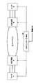
- Fig. 1 shows the conventional network configuration.
- a transfer layer L2/L3 device
- a transmission layer L0/L1 device
- An example of a transfer layer service is a VPN (Virtual Private Network) service
- an example of a transmission layer service is a wavelength dedicated leased line service.
- the redundant configuration that can be set in the transfer layer VPN is limited to the configuration that can be realized in the transfer layer (transfer protection, no redundancy, etc.).
- Transmission restration exists as a redundant configuration of the transmission layer, but the redundant configuration of the transmission layer is applied to the entire underlay NW or each path of the underlay NW when constructing a VPN in the forwarding layer.
- the transfer layer and the redundant layer are managed independently of each other, and the redundant structure of the path is also secured by each layer, so the redundant structure of the transmission layer is set for each VPN of the transfer layer. Can not do it. As a result, it may not be possible to adequately meet the various reliability requirements envisioned for 5G NW use cases.
- the purpose of the present invention is to provide a transfer path that satisfies more reliability requirements by making it possible to apply a redundant configuration of the transfer layer to the transfer path of the transfer layer.
- a control device is A control device used in a communication network composed of a plurality of routers and a plurality of transmission devices for connecting the plurality of routers, A transmission path that connects the transmission devices, and a transmission configuration information storage unit that manages whether or not a redundant configuration in the transmission layer is available for the transmission path, A route information storage unit that manages a route set between the routers and a transmission path used in the route, A redundant configuration in the transfer layer is obtained as a requirement for the redundant configuration by referring to the transmission configuration information storage unit and the route information storage unit in response to an opening request including a redundant configuration requirement for a transfer path connecting routers.
- a transfer path opening implementation unit that opens a transfer path that does not use the route of It is characterized by having.
- control method implemented by a control device used in a communication network configured by a plurality of routers and a plurality of transmission devices for connecting the plurality of routers, A transmission path connecting the transmission devices, and a step of managing in the transmission configuration information storage unit whether or not a redundant configuration in the transmission layer is available for the transmission path, A step of managing a route set between the routers and a transmission path used in the route in the route information storage section; A redundant configuration in the transfer layer is obtained as a requirement for the redundant configuration by referring to the transmission configuration information storage unit and the route information storage unit in response to an opening request including a redundant configuration requirement for a transfer path connecting routers.
- a transfer path that uses a redundant route is opened, and if a redundant configuration in the transmission layer is required as a requirement for the redundant configuration, the redundant path associated with the redundant configuration in the transmission layer is associated with the redundant configuration.
- the step of opening a transfer path that does not use the route of It is characterized by having.
- the present invention by making it possible to apply the redundant configuration of the transfer layer to the transfer path of the transfer layer, it becomes possible to provide a transfer path that satisfies more reliability requirements.
- FIG. 6 is a block configuration diagram of an SDN controller/NMS according to a second embodiment of the present invention. It is an example of the transmission path information held in the transmission path information DB. It is an example of user connection information held in the user connection information DB. It is an example of the L2 switch connection information held in the L2 switch connection information DB. 3 is a hardware configuration example of the SDN controller/NMS according to the embodiment of the present invention.
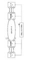
- FIG. 2 shows the configuration of an IP (Internet Protocol)/transmission network in the embodiment of the present invention.
- the IP/transmission network is composed of routers A and B and transmission devices A and B.
- a transmission layer network (hereinafter referred to as an optical network) is configured by the transmission devices A and B, and a transfer layer IP network is configured by connecting the routers A and B to the optical network.
- An SDN (Software Defined Network) controller/NMS (Network Management System) 100 is an example of a control device that controls a router and a transmission device.
- the control device that controls the router and the transmission device is described as the SDN controller/NMS 100, but the SDN controller/NMS 100 may be a control device that has both the SDN controller and NMS functions, and the SDN controller only functions. It may be a control device having the same, a control device having only an NMS function, or another control device independent of the SDN controller and the NMS.
- FIG. 2 shows two routers and two transmission devices, any number of routers and transmission devices may be used to form an IP/transmission network.
- the optical network is composed of transmission equipment such as CDC-ROADM (Colorless, Directionless and Contentionless-Reconfigurable Optical Add/Drop Multiplexer) that can dynamically change the wavelength of the optical wavelength path.
- CDC-ROADM Colorless, Directionless and Contentionless-Reconfigurable Optical Add/Drop Multiplexer
- the present embodiment can be applied to a configuration in which the bases are connected one-to-one using only the transponder.
- the router is a router that can control the route by Segment Routing or the like. However, if route control is possible, the present embodiment can be applied even when MPLS (Multi-Protocol Label Switching) or IP routing is used.
- MPLS Multi-Protocol Label Switching
- the transfer path is a path set in the transfer layer, and a VPN service is an example of a service using the transfer path.
- the transmission path is a path set in the transmission layer, and an example of a service using the transmission path is a dedicated wavelength leased line service.
- the transfer path used in the VPN service is simply called a VPN, and the transmission path used in the wavelength occupied leased line service is called an optical wavelength path.
- a request for opening a transmission path includes a requirement for a redundant configuration. If a path can be configured according to the requirement (redundant configuration), the SDN controller/NMS 100 is not limited to direct control from the autonomous distributed protocol between devices. The present embodiment can be applied to a configuration using the above.
- the physical wiring information and port information between the router and the transmission device described below are registered in the SDN controller/NMS100.
- Figure 3 shows an example of the physical connection configuration of the device and the configuration example of the optical wavelength.
- Optical wavelength paths are set between the transmission devices, and the routers communicate with each other by using the optical wavelength paths between the transmission devices.
- a transmission restoration which is a redundant configuration of the transmission layer, can be set in the optical wavelength path.
- An optical wavelength path (optical wavelength path ID 3) that uses wavelength ⁇ 3 for which transmission restration is not set between the physical port 5 of transmission device A and the physical port 5 of transmission device B
- the SDN controller/NMS 100 determines the optical wavelength path of the transmission restoration control target.
- the bypass route used at the time of transmission restoration by the SDN controller/NMS 100 may be statically set, or the available route may be automatically calculated by the SDN controller/NMS 100.
- Fig. 4 shows an example of route control between routers. It is assumed that a plurality of routes can be set between the routers, and a route that can be used between the routers can be selected by an instruction from the SDN controller/NMS 100. As an example, it is assumed that the router A and the router B are connected by three routes as shown in FIG. 4, and which route to use can be selected by an instruction from the SDN controller/NMS 100. For example, when using Segment Routing, set the SID (Segment ID) used in Segment Routing as the Adjacency SID for the link, and specify the route used by the LSP (Label Switched Path) from the SDN controller/NMS100 with the SID. Thus, the communication route can be controlled for each VPN.
- the SID settings for the router include standard protocol settings such as NETCONF (Network Protocol)/YANG (Yet Another Next Generation) and PCEP (Path Computation Element Protocol), and CLI (Command Line Interface).
- FIG. 5 shows a network configuration of the embodiment of the present invention described in FIGS. 2 to 4.
- the SDN controller/NMS 100 controls the entire system including the transmission layer and the transfer layer.
- the SDN controller/NMS 100 receives a transfer path opening request, and sets a transfer path (VPN) that satisfies the redundancy requirement required in the opening request.
- VPN transfer path
- the SDN controller/NMS 100 manages not only the redundant configuration of the transfer layer but also the redundant configuration of the transmission layer, so that the transmission layer redundancy that can be used for each route of the underlay NW when the transfer path is constructed.
- the configuration is identified, and the transfer path is opened by a route that meets the requirements of the transfer path opening request.
- the SDN controller/NMS 100 can set a plurality of redundant configurations (transfer protection/transmission restoration/no redundancy) for the transfer path.
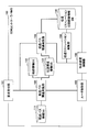
- FIG. 6 shows a block diagram of the SDN controller/NMS 100 according to the first embodiment of the present invention.
- the SDN controller/NMS 100 includes a request receiving unit 101 as a functional unit, a transfer path opening execution unit 102, a transmission path opening execution unit 103, a transmission restoration execution unit 104, a router control unit 105, and a transmission device control unit. And 106. Further, the SDN controller/NMS 100 has a transfer path information DB 111 as a storage unit, a route information DB 112, a transmission configuration information DB 113, and a transmission restoration bypass route information DB 114.
- FIG. 8 shows a case where the Segment list is composed of one segment, when there are a plurality of segments between routers, a plurality of SIDs are included in the Segment list.
- the transmission configuration information DB 113 is a storage unit that manages information on optical wavelength paths set between transmission devices.
- the transmission configuration information DB 113 stores the connection information of the physical configuration as shown in FIG. 3 in the format as shown in FIG. 9 for each optical wavelength path by the transmission device, the port, the wavelength, and the redundant configuration (transmission list). Holds the presence/absence of control (rate control).
- the transmission restoration bypass route information DB 114 is a storage unit that manages the bypass route information for transmission restoration control.
- the request receiving unit 101 receives a request for opening including a redundant configuration requirement (transfer protection/transmission restoration/no redundancy) for a transfer path (VPN).
- the opening request also includes the start and end points of the transfer path. This may be a request from the outside of the SDN controller/NMS 100, or a request from a result calculated by an algorithm preset in the SDN controller/NMS 100.
- the transfer path opening execution unit 102 searches the route information DB 112 for a route that can realize a redundant configuration of the transfer path opening request in response to the opening request, and searches the transmission configuration information DB 113 for a route that can realize the redundant configuration of the opening request. Search for.
- the transfer path opening execution unit 102 When the transmission restoration is required as a requirement for the redundant configuration when opening the transfer path (VPN1), the transfer path opening execution unit 102 does not have the redundant configuration associated with the transmission path for which the transmission restoration is set.
- the transfer path needs to be opened. Specifically, the transfer path establishment unit 102 first searches the transmission configuration information DB 113 for a wavelength ( ⁇ 1) for which transmission restoration is valid (Enable), and then searches for a wavelength ( ⁇ 1) for which transmission restoration is valid.
- a segment list name that is being used and has the same start point and end point of the requested transfer path is searched from the route information DB 112. If there are multiple available Segment list names, the shortest path may be detected dynamically, or a dynamic decision using some weighting algorithm or a static decision selected by the operator may be made. Good.
- Segment Routing specifies routes for each direction, two sets make up one set in the case of two-way communication, and it is necessary to extract two routes from the start point to the end point and the end point to the start point.
- Transfer path information as shown in the first line of FIG. 7 is created based on the information thus extracted. In the case of transmission restoration, transfer protection is not set, so Backup-path is Null.
- the transfer path opening execution unit 102 registers information in the transfer path information DB 111 and sets the transfer path (VPN1) for the start point/end point routers via the router control unit 105.
- open API Application Programming Interface
- the transfer path opening execution unit 102 When no redundancy is required as a requirement for the redundant configuration when opening the transfer path (VPN2), the transfer path opening execution unit 102 does not have a redundant structure associated with the transfer path for which the transmission restoration is not set.
- the transfer path needs to be opened. Specifically, the transfer path establishment unit 102 first searches the transmission configuration information DB 113 for the wavelength ( ⁇ 2, ⁇ 3) for which the transmission restoration is disabled, and then searches for the wavelength for which the transmission restoration is invalid ( ⁇ 2). , ⁇ 3) is used and the segment list name in which the start point and the end point of the requested transfer path match is searched from the route information DB 112.
- the shortest path may be detected dynamically, or a dynamic decision using some weighting algorithm or a static decision selected by the operator may be made. Good.
- Segment Routing specifies routes for each direction, two sets make up one set in the case of two-way communication, and it is necessary to extract two routes from the start point to the end point and the end point to the start point. Based on the information thus extracted, transfer path information as shown in the second line of FIG. 7 is created. If there is no redundancy, transfer protection is not set, so Backup-path is Null.
- the transfer path opening execution unit 102 registers information in the transfer path information DB 111 and sets the transfer path (VPN2) for the start point/end point routers via the router control unit 105.
- the transfer path opening execution unit 102 transfers the redundant configuration associated with the transfer path for which the transmission restoration is not set. You need to open the pass. Specifically, the transfer path establishment unit 102 first searches the transmission configuration information DB 113 for the wavelength ( ⁇ 2, ⁇ 3) for which the transmission restoration is disabled, and then searches for the wavelength for which the transmission restoration is invalid ( ⁇ 2). , ⁇ 3) is used and the segment list name in which the start point and the end point of the requested transfer path match is searched from the route information DB 112. In this case, there must be two available Segment list names for Active-Path and Backup-Path.
- the shortest path may be dynamically detected, or a dynamic decision using some weighting algorithm or a static decision selected by the operator may be made. Similarly, which of the two determined routes should be the Active-Path may be determined.
- Segment Routing specifies routes for each direction, two sets make up one set in the case of two-way communication, and it is necessary to extract two routes from the start point to the end point and the end point to the start point. Based on the information thus extracted, transfer path information as shown in the third line of FIG. 7 is created. In the case of transfer protection, Backup-path is a path not selected as Active-Path.
- the transfer path opening execution unit 102 registers information in the transfer path information DB 111, and sets the transfer path (VPN3) for the start point/end point routers via the router control unit 105.
- the transfer path opening execution unit 102 requests the transmission path opening execution unit 103 to open the transmission path when there is no transmission path in the transmission configuration information DB 113 that satisfies the requirement for the redundant configuration of the transmission layer. .. For example, when the transfer path opening execution unit 102 cannot find a wavelength for which the transmission restoration is valid from the transmission configuration information DB 113, the transfer path opening execution unit 102 notifies the transmission path opening execution unit 103 of the transmission restoration. Requests the opening of the set transmission path.
- the transmission path opening execution unit 103 opens the transmission path and registers information on the opened transmission path in the transmission configuration DB 113.
- the transmission path opening execution unit 103 validates the transmission restoration control when registering the information in the transmission configuration information DB 113 of FIG.
- the registered transmission path is registered.
- the transmission path opening execution unit 103 disables the transmission restoration control when registering the information in the transmission configuration information DB 113 of FIG. Register the selected transmission path.
- the operator may manually register the port or wavelength to be used, or may be automatically allocated from other information such as the resource pool.
- the transmission path opening execution unit 103 opens the transmission path by registering information in the transmission configuration information DB 113 and setting the transmission device via the transmission device control unit 106.
- the method of inputting the settings to the transmission device may be an open API such as Netconf or a protocol unique to the transmission device.
- the transmission restoration execution unit 104 searches the transmission configuration information DB 113 for the wavelength that uses the alerted port and specifies the wavelength. To do. For example, when a failure occurs between the physical port 4 of the transmission device A and the physical port 4 of the transmission device B, the physical port 4 of the transmission device A and the physical port 4 of the transmission device B are used from the transmission configuration information DB 113. The wavelengths ( ⁇ 1, ⁇ 2) that are present. Since the transmission restoration control is disabled (Disable), the wavelength ⁇ 2 is not bypassed to the bypass route.
- the optical wavelength path of wavelength ⁇ 1 is detoured to the detour path between the physical port 5 of the transmission device A and the physical port 5 of the transmission device B.
- the SDN controller/NMS 100 centrally holds multi-layer (transmission layer/transfer layer) information, so that it is possible to set a redundant configuration of the transfer layer for the transfer layer path.
- a link between routers that is a route of the transfer path is used.
- the redundant configuration By determining the route of the transfer path based on the information of the redundant configuration of the wavelength path of the transmission layer (transmission restoration/non-redundancy), the redundant configuration (transfer protection In addition to (no redundancy), a redundant configuration (redundant protection) realized in the transmission layer can be set.
- the router and the transmission device are not directly connected as shown in FIG. 2, but the L2 switch and the user/router/transmission device are respectively connected as shown in FIG.
- the end point of the network path is the port of the L2 switch to which the router or the transmission device is connected, and the connection point of the user is the port of the same L2 switch.
- FIG. 11 shows the configuration of the IP/transmission network in the second embodiment of the present invention.
- routers A and B and transmission devices A and B are used to connect between the L2 switch A and the L2 switch B to which the user connects.
- FIG. 11 shows two routers and two transmission devices, any number of routers and transmission devices may be used to form an IP/transmission network.
- the present embodiment can be applied even if the connection configuration of the optical network is changed as long as the L2 switch and the user/router/transmission device are connected.
- the user can set the transmission path to which the transmission restoration is set from the same end point (L2 switch).
- a transfer path using transfer protection is made available.
- FIG. 12 shows a configuration example of the transmission path in the second embodiment of the present invention.
- the SDN controller/NMS 100 opens a transmission path between the transmission device A and the transmission device B, which satisfies the requirement of the redundant configuration of the transmission layer (transmission restoration/no redundancy).
- the SDN controller/NMS100 configures the transmission path on the network according to the redundant configuration of the transmission path, and also connects the user's connection port in the L2 switch and the port of the L2 switch which is the end point of the configured transmission path.
- an associating means will be described by using an example of using a VLAN (Virtual Local Area Network), but the present embodiment can be used even if another technique is used as long as the communication of the connection port can be passed through the transmission path. Can be applied.
- FIG. 13 shows a configuration example of the transfer path in the second embodiment of the present invention.
- the SDN controller/NMS100 transfers the transfer path between the router A and the router B via the transmission devices A and B to satisfy the transfer layer redundancy configuration requirement (transfer protection/no redundancy).
- transfer protection/no redundancy transfer protection/no redundancy
- FIG. 14 shows a block diagram of the SDN controller/NMS 100 according to the second embodiment of the present invention.
- the SDN controller/NMS 100 further includes a network path determination execution unit 107 as a functional unit, an L2 switch internal opening execution unit 108, and an L2 switch control unit 109.
- the SDN controller/NMS 100 further includes a transmission path information DB 115 as a storage unit, a user connection information DB 116, and an L2 switch connection information DB 117.
- the transmission path information DB 115 is a storage unit that manages the transmission path set in response to the user's opening request.
- the transmission path information DB 115 information on the end points of the transmission path opened by the transmission path opening execution unit 103 described below is registered. For example, in the example shown in FIG. 12, when the transmission path in which the transmission restoration between the transmission devices A and B is set between the L2 switches A and B is opened, the transmission path information DB 115 stores the information as shown in FIG. Hold.
- the user connection information DB 116 is a storage unit that manages connection information on the user side of network paths (transmission path and transfer path) set in response to a user's opening request.
- the transmission path and the transfer path opened by the transmission path opening execution unit 103 and the transfer path opening execution unit 102 described below are stored in the user side of the L2 switch in the format shown in FIG. Holds port information.
- the L2 switch connection information DB 117 is a storage unit that manages information on the VLAN set in the L2 switch.
- the L2 switch connection information DB 117 holds information on the VLAN in the L2 switch opened by the L2 switch internal opening execution unit 108 described below in a format as shown in FIG.
- the request receiving unit 101 receives from a user a request for opening including a redundant configuration requirement (transfer protection/transmission restoration/no redundancy) for a network path.
- a redundant configuration requirement transfer protection/transmission restoration/no redundancy
- This may be a request from the outside of the SDN controller/NMS 100, or a request from a result calculated by an algorithm preset in the SDN controller/NMS 100. It is assumed that the opening request includes a condition (redundant configuration) necessary for constructing a user connection point and a network path.
- the network path determination execution unit 107 determines whether the requested network path is a transmission path or a transfer path. If it is a transfer path, the transfer path opening execution unit 102 issues a transfer path opening request for opening the transfer path. If it is a transmission path, the transmission path opening execution unit 103 issues a transmission path opening request for opening the transmission path.
- the network path determination execution unit 107 needs to request the transfer path opening execution unit 102 to open the transfer path for which the transfer protection is set. ..
- the redundant restoration is required as a requirement for the redundant configuration
- the network path determination execution unit 107 needs to make a request to the transmission path opening execution unit 103 to open the transmission path for which the redundant restoration is set. There is.
- the transfer path opening execution unit 102 registers information in the user connection information DB 116 in addition to the transfer path information DB 111, and transfers the transfer path to the start point/end point routers via the router control unit 105. Perform the setting of.
- the method of inputting the settings to the router may be an open API such as Netconf or a router-specific protocol.
- the transmission path opening execution unit 103 generates transmission path information in response to the transmission path opening request, registers the information in the transmission configuration information DB 113 as in the first embodiment, and transmits the transmission path information DB 115 and the user connection information DB 116. Register information in.
- the generation of configurable transmission path information may be calculated by an algorithm in the SDN controller/NMS 100 or may be given from the outside. For example, when the transmission path for which the transmission restoration is set is requested from the user 1, as shown in FIG. 12, the transmission path for which the transmission restoration is set is set between the physical ports 4 of the transmission devices A and B. Make it open.
- the transmission path opening execution unit 103 registers information in the transmission path information DB 115 and the user connection information DB 116 in addition to the transmission configuration information DB 113 and sets it in the transmission device via the transmission device control unit 106.
- the method of inputting the settings to the transmission device may be an open API such as Netconf or a protocol unique to the transmission device.
- the L2 switch internal opening execution unit 108 connects the port of the L2 switch, which is the end point of the opened network path (transfer path or transfer path), and the user's connection point in the L2 switch of the start point/end point to which the user connects.
- the L2 switch internal opening execution unit 108 uses the L2 switch user connection port information and the network path end point port associated with the network path constructed by the transfer path opening execution unit 102 or the transmission path opening execution unit 103, respectively.
- the information is acquired from the user connection information DB 116 or the transmission path information DB 115, and the information is registered in the L2 switch connection information DB 117.
- the VLAN information (VLAN1, VLAN2) in the L2 switch connection information DB may be set automatically from the VLAN number that the controller has available, or may be set statically. Based on the information registered in the L2 switch connection information DB 117, the L2 switch internal opening execution unit 108 connects between the connection port of the user and the port of each L2 switch at the end point of the network path via the L2 switch control unit 109. Enable communication.
- the method of opening the ports of the L2 switch is not limited to VLAN, and routing, VXLAN (Virtual eXtensible Local Area Network), etc. may be used.
- the method of inputting the settings to the L2 switch may be an open API such as Netconf or a protocol unique to the L2 switch.
- the end points of the transmission path (wavelength dedicated line) and transfer path (L2VPN/L3VPN) are accommodated in the same L2 switch, and the user's connection point is also the same L2 switch.
- the controller controls the controller so that the port of the L2 switch used at the end point of the transfer path or the transmission path and the port of the L2 switch at the connection point of the user can communicate, various conditions can be met.
- the transmission path and the transfer path can be provided at the same connection point.
- Transmission restoration is a technology that restores the transmission path by switching the wavelength path by the transmission equipment when the transmission path fails, but since it generally takes some time to control the transmission equipment, the communication interruption time before restoration Is longer than transfer protection.
- the transmission device completes the wavelength route switching, the user's traffic is temporarily accommodated in the transfer path or the transmission path that has been opened, and after the wavelength route switching is completed, By re-accommodating the user traffic in the transmission path, it is possible to shorten the communication interruption time of the transmission restoration.
- a transfer path or a transmission path that has been opened and is temporarily used is called a temporary detour path
- a transmission path after a route switching is called a detour path.
- the temporary detour path may be opened as a dedicated path for this purpose, or the path used by other existing users may be shared.
- an available path may be selected from the contract bandwidth of the transmission path subject to the transmission restoration, or may be selected by another logic.
- the block configuration diagram of the SDN controller/NMS 100 of the third embodiment is the same as the block configuration diagram of the first embodiment shown in FIG. 6 or the block configuration diagram of the second embodiment shown in FIG.
- the transmission restoration execution unit 104 uses the opened transfer path as a temporary bypass of the transfer path (VPN1). You may use it as a pass.
- the transmission restoration execution unit 104 specifies the transfer path or the transfer path affected by the alert as described above.
- the wavelength restoration control of the specified transfer path or transmission path is enabled (Enable)
- the affected transfer path or transmission path is diverted to the temporary detour path until the wavelength path switching is completed, and the wavelength After the route switching is completed, the temporary detour path is detoured to the detour path.
- the L2 switch internal opening execution unit 108 connects the end point of the temporary detour path and the connection point of the user.
- the transmission restoration implementation unit 104 selects a transfer path that is a transmission restoration target or a temporary bypass path that bypasses the transmission path
- the L2 switch that is the end point of the transfer path or the transmission path. Port is identified by referring to the L2 switch connection information DB 117.
- the port of the L2 switch that is the end point of the temporary detour path is also identified by referring to the L2 switch connection information DB 117.
- the L2 switch internal opening execution unit 108 connects the port of the L2 switch, which is the end point of the temporary detour path, and the connection port of the user.
- the L2 switch internal opening execution unit 108 connects the end point of the detour path and the connection point of the user. Specifically, when the transmission restoration execution unit 104 selects a detour path of the transmission path subject to the transmission restration, the port of the L2 switch, which is the end point of the detour path, is stored in the L2 switch connection information DB 117. Refer to identify.
- the L2 switch internal opening execution unit 108 reassociates the port of the L2 switch, which is the end point of the temporary detour path connected to the connection port of the user, with the port of the L2 switch, which is the end point of the detour path. ..
- FIG. 18 shows a hardware configuration example of the SDN controller/NMS 100 according to the embodiment of the present invention.
- the SDN controller/NMS 100 may be a computer including a processor such as a CPU (Central Processing Unit) 151, a memory device 152 such as a RAM (Random Access Memory) and a ROM (Read Only Memory), and a storage device 153 such as a hard disk. ..
- the functions and processing of the SDN controller/NMS 100 are realized by the CPU 151 executing data or programs stored in the storage device 153 or the memory device 152.
- the input of data to the SDN controller/NMS 100 may be performed from the input/output interface device 154, and the output of data from the SDN controller/NMS 100 may be performed from the input/output interface device 154.
- the device according to the embodiment of the present invention is described using a functional block diagram.
- the device according to the embodiment of the present invention may be realized by hardware, software, or a combination thereof.
- the embodiment of the present invention includes a program that causes a computer to implement the functions of the device according to the embodiment of the present invention, a program that causes a computer to execute each procedure of the method according to the embodiment of the present invention, and the like. May be realized.
- each functional unit may be used in combination as necessary.
- the method according to the embodiment of the present invention may be performed in a different order from the order shown in the embodiment.
- SDN controller/NMS 101 request reception unit 102 transfer path opening execution unit 103 transmission path opening execution unit 104 transmission restoration execution unit 105 router control unit 106 transmission device control unit 107 network path determination execution unit 108 L2 switch internal opening execution unit 109 L2 switch control unit 111 Transfer path information DB 112 Route information DB 113 Transmission configuration information DB 114 Transmission Restoration Route Information DB 115 Transmission path information DB 116 User connection information DB 117 L2 switch connection information DB
Landscapes
- Engineering & Computer Science (AREA)
- Computer Networks & Wireless Communication (AREA)
- Signal Processing (AREA)
- Data Exchanges In Wide-Area Networks (AREA)
Abstract
制御装置は、伝送装置間を接続する伝送パスと、当該伝送パスに対して伝送レイヤにおける冗長構成が利用可能であるか否かを管理する伝送構成情報記憶部と、ルータ間に設定された経路と、当該経路で用いられる伝送パスとを管理する経路情報記憶部と、ルータ間を接続する転送パスに対する冗長構成の要件を含む開通要求に応じて、前記伝送構成情報記憶部及び前記経路情報記憶部を参照して、当該冗長構成の要件として転送レイヤにおける冗長構成が求められた場合には、冗長の経路を利用する転送パスを開通させ、当該冗長構成の要件として伝送レイヤにおける冗長構成が求められた場合には、伝送レイヤにおける冗長構成の伝送パスに紐付く、冗長の経路を利用しない転送パスを開通させる転送パス開通実施部とを有する。
Description
本発明は、制御装置及び制御方法に関する。
5G時代のネットワークは、キャリア網の仮想化(NWスライス)が重要であり、サービス提供の迅速性も必要となるためSDN(Software Defined Network)技術を用いて実現していく必要がある。また、5GではIoT(Internet of Things)・自動運転・高解像度動画配信等の多様なサービスが想定されており、NWスライスとしても多様な要件のネットワークを構築する必要がある。
一方で、キャリア網において5Gにおける多様なNWスライスを実現するためのNWパスを実現するためには、伝送レイヤ・転送レイヤの統合制御(マルチレイヤSDN制御)が課題となり、それらを管理する手段がONOS(Open Network Operating System)やONAP(Open Network Automation Platform)のようなOSS(Open Source Software)プロジェクトで検討されている(非参考文献1及び2参照)。
ONOS, インターネット<URL:https://onosproject.org/>, 平成30年12月20日検索
ONAP, インターネット<URL:https://www.onap.org/>, 平成30年12月20日検索
NTT DOCOMOテクニカル・ジャーナル, Vol.23, No.4, 76~77ページ, インターネット<URLhttps://www.nttdocomo.co.jp/binary/pdf/corporate/technology/rd/technical_journal/bn/vol23_4/vol23_4_000jp.pdf>, 平成30年12月20日検索
5Gでは適切な信頼性確保とコスト削減を実現するために、収容する端末やデバイスのトラフィック特性や優先度に応じて、サービス要求レベルを調整してネットワークを設計することが想定されている(非特許文献3参照)。例えば、5GではIoT等の高すぎる信頼性を求めないNWのユースケースも定義されることが想定される。
図1に、従来のネットワーク構成を示す。図1に示すように、従来のネットワーク構成は、転送レイヤ(L2/L3装置)と伝送レイヤ(L0/L1装置)が別々に構成される。転送レイヤのサービスの例としてVPN(Virtual Private Network)サービスがあり、伝送レイヤのサービスの例として波長占有専用線サービスがある。従来、転送レイヤのVPNに設定可能な冗長構成は転送レイヤで実現可能な構成(転送プロテクション・冗長なし等)に限られる。伝送レイヤの冗長構成として伝送リストレーションが存在するが、伝送レイヤの冗長構成は転送レイヤにおいてVPNを構築する際のアンダーレイNW全体あるいはアンダーレイNWのパス毎に適用されるものである。このように、転送レイヤと冗長レイヤはそれぞれ独立して管理されており、パスの冗長構成もそれぞれのレイヤで担保する仕組みとなっているため、転送レイヤのVPN毎に伝送レイヤの冗長構成を設定することができない。その結果、5GのNWのユースケースで想定される多様な信頼性の要件に十分に対応できない可能性がある。
本発明は、転送レイヤの転送パスに対して伝送レイヤの冗長構成を適用可能にすることで、より多くの信頼性の要件を満たす転送パスを提供することを目的とする。
本発明の一形態に係る制御装置は、
複数のルータと、当該複数のルータ間を接続するための複数の伝送装置とで構成される通信ネットワークにおいて用いられる制御装置であって、
伝送装置間を接続する伝送パスと、当該伝送パスに対して伝送レイヤにおける冗長構成が利用可能であるか否かを管理する伝送構成情報記憶部と、
ルータ間に設定された経路と、当該経路で用いられる伝送パスとを管理する経路情報記憶部と、
ルータ間を接続する転送パスに対する冗長構成の要件を含む開通要求に応じて、前記伝送構成情報記憶部及び前記経路情報記憶部を参照して、当該冗長構成の要件として転送レイヤにおける冗長構成が求められた場合には、冗長の経路を利用する転送パスを開通させ、当該冗長構成の要件として伝送レイヤにおける冗長構成が求められた場合には、伝送レイヤにおける冗長構成の伝送パスに紐付く、冗長の経路を利用しない転送パスを開通させる転送パス開通実施部と、
を有することを特徴とする。
複数のルータと、当該複数のルータ間を接続するための複数の伝送装置とで構成される通信ネットワークにおいて用いられる制御装置であって、
伝送装置間を接続する伝送パスと、当該伝送パスに対して伝送レイヤにおける冗長構成が利用可能であるか否かを管理する伝送構成情報記憶部と、
ルータ間に設定された経路と、当該経路で用いられる伝送パスとを管理する経路情報記憶部と、
ルータ間を接続する転送パスに対する冗長構成の要件を含む開通要求に応じて、前記伝送構成情報記憶部及び前記経路情報記憶部を参照して、当該冗長構成の要件として転送レイヤにおける冗長構成が求められた場合には、冗長の経路を利用する転送パスを開通させ、当該冗長構成の要件として伝送レイヤにおける冗長構成が求められた場合には、伝送レイヤにおける冗長構成の伝送パスに紐付く、冗長の経路を利用しない転送パスを開通させる転送パス開通実施部と、
を有することを特徴とする。
また、本発明の一形態に係る制御方法は、
複数のルータと、当該複数のルータ間を接続するための複数の伝送装置とで構成される通信ネットワークにおいて用いられる制御装置が実施する制御方法であって、
伝送装置間を接続する伝送パスと、当該伝送パスに対して伝送レイヤにおける冗長構成が利用可能であるか否かを伝送構成情報記憶部において管理するステップと、
ルータ間に設定された経路と、当該経路で用いられる伝送パスとを経路情報記憶部において管理するステップと、
ルータ間を接続する転送パスに対する冗長構成の要件を含む開通要求に応じて、前記伝送構成情報記憶部及び前記経路情報記憶部を参照して、当該冗長構成の要件として転送レイヤにおける冗長構成が求められた場合には、冗長の経路を利用する転送パスを開通させ、当該冗長構成の要件として伝送レイヤにおける冗長構成が求められた場合には、伝送レイヤにおける冗長構成の伝送パスに紐付く、冗長の経路を利用しない転送パスを開通させるステップと、
を有することを特徴とする。
複数のルータと、当該複数のルータ間を接続するための複数の伝送装置とで構成される通信ネットワークにおいて用いられる制御装置が実施する制御方法であって、
伝送装置間を接続する伝送パスと、当該伝送パスに対して伝送レイヤにおける冗長構成が利用可能であるか否かを伝送構成情報記憶部において管理するステップと、
ルータ間に設定された経路と、当該経路で用いられる伝送パスとを経路情報記憶部において管理するステップと、
ルータ間を接続する転送パスに対する冗長構成の要件を含む開通要求に応じて、前記伝送構成情報記憶部及び前記経路情報記憶部を参照して、当該冗長構成の要件として転送レイヤにおける冗長構成が求められた場合には、冗長の経路を利用する転送パスを開通させ、当該冗長構成の要件として伝送レイヤにおける冗長構成が求められた場合には、伝送レイヤにおける冗長構成の伝送パスに紐付く、冗長の経路を利用しない転送パスを開通させるステップと、
を有することを特徴とする。
本発明によれば、転送レイヤの転送パスに対して伝送レイヤの冗長構成を適用可能にすることで、より多くの信頼性の要件を満たす転送パスを提供することが可能になる。
以下、図面に基づいて本発明の実施形態を説明する。
本発明の実施形態では、転送レイヤの転送パスに対して伝送レイヤの冗長構成を適用可能にする制御装置について説明する。
図2に、本発明の実施形態におけるIP(Internet Protocol)/伝送ネットワークの構成を示す。図2に示すように、IP/伝送ネットワークは、ルータA, Bと、伝送装置A, Bとで構成される。伝送装置A, Bによって伝送レイヤのネットワーク(以下、光ネットワークと呼ぶ)が構成されており、ルータA, Bを光ネットワークに接続することで、転送レイヤのIPネットワークが構成されている。SDN(Software Defined Network)コントローラ/NMS(Network Management System)100は、ルータと伝送装置を制御する制御装置の例である。本実施形態ではルータと伝送装置を制御する制御装置をSDNコントローラ/NMS100と記載するが、SDNコントローラ/NMS100は、SDNコントローラ及びNMSの双方の機能を有する制御装置でもよく、SDNコントローラのみの機能を有する制御装置でもよく、NMSのみの機能を有する制御装置でもよく、SDNコントローラ及びNMSとは独立した他の制御装置でもよい。なお、図2には、2つのルータと2つの伝送装置が示されているが、IP/伝送ネットワークを構成するために如何なる数のルータ及び伝送装置が用いられてもよい。
光ネットワークは、光波長パスの波長を動的に変えることができるCDC-ROADM(Colorless, Directionless and Contentionless-Reconfigurable Optical Add/Drop Multiplexer)等の伝送装置で構成されていることを前提とする。但し、光波長パスの波長を動的に変えることができれば、トランスポンダのみを用いて拠点間を1対1で接続する構成でも、本実施形態は適用することができる。また、ルータは、Segment Routing等によって経路を制御することができるルータである。但し、経路制御が可能であれば、MPLS(Multi-Protocol Label Switching)やIPルーティングが用いられる場合にも、本実施形態は適用することができる。
ルータ及び伝送装置はSDNコントローラ/NMS100が受け取るパス開通要求の条件に応じた転送パス及び伝送パスを開通できることを前提とする。転送パスとは転送レイヤにおいて設定されるパスであり、転送パスを利用したサービスの例としてVPNサービスがある。伝送パスとは伝送レイヤにおいて設定されるパスであり、伝送パスを利用したサービスの例として波長占有専用線サービスがある。以下の説明において、VPNサービスにおいて用いられる転送パスを単にVPNと呼び、波長占有専用線サービスにおいて用いられる伝送パスを光波長パスと呼ぶ。伝送パス開通要求には冗長構成の要件が含まれており、要求条件(冗長構成)に応じたパスが構成できれば、SDNコントローラ/NMS100がからの直接制御に限らず装置間の自律分散型のプロトコル等を利用した構成でも本実施形態は適用することができる。
以下に説明するルータ及び伝送装置間の物理配線情報・ポート情報はSDNコントローラ/NMS100に登録されているものとする。
図3に、装置の物理的な接続構成例と光波長の構成例を示す。伝送装置間に光波長パスが設定され、ルータは伝送装置間の光波長パスを利用することにより、互いに通信する。光波長パスには伝送レイヤの冗長構成である伝送リストレーションを設定できる。一例として、伝送装置Aの物理ポート4と伝送装置Bの物理ポート4との間に、伝送リストレーションが設定された波長λ1を用いる光波長パス(光波長パスID=1)が設定されているものとする。さらに、伝送装置Aの物理ポート4と伝送装置Bの物理ポート4との間に、伝送リストレーションが設定されていない波長λ2を用いる光波長パス(光波長パスID=2)が設定されており、伝送装置Aの物理ポート5と伝送装置Bの物理ポート5との間に、伝送リストレーションが設定されていない波長λ3を用いる光波長パス(光波長パスID=3)が設定されているものとする。
伝送装置Aの物理ポート4と伝送装置Bの物理ポート4との間で障害が発生し、光波長パスの接続断が発生した場合、SDNコントローラ/NMS100は、伝送リストレーション制御対象の光波長パス(光波長パスID=1)を伝送装置Aの物理ポート5と伝送装置Bの物理ポート5との間に迂回させて復旧する。ただし、伝送リストレーション制御非対象の光波長パス(光波長パスID=2, 3)は、接続断が発生した場合でも、SDNコントローラ/NMS100による迂回制御は行われない。SDNコントローラ/NMS100による伝送リストレーション時に用いる迂回経路は静的に設定していてもよく、利用可能な経路をSDNコントローラ/NMS100によって自動的に計算してもよい。
図4に、ルータ間の経路制御の例を示す。ルータ間には複数の経路が設定可能であり、SDNコントローラ/NMS100からの指示により、ルータ間で使用できる経路を選択できるものとする。一例として、ルータAとルータBは、図4に示すように3つの経路で接続され、SDNコントローラ/NMS100からの指示によりどちらの経路を使用するか選択できるものとする。例えば、Segment Routingを用いる場合は、リンクにAdjacency SIDとしてSegment Routingで使用するSID(Segment ID)を設定し、SDNコントローラ/NMS100から、LSP(Label Switched Path)が使用する経路をSIDで指定することで、VPN毎に通信経路を制御することができる。ルータへのSIDの設定は、NETCONF(Network Configuration Protocol)/YANG(Yet Another Next Generation)やPCEP(Path Computation Element Protocol)等の標準プロトコルによる設定、CLI(Command Line Interface)による設定がある。
SDNコントローラ/NMS100は、ルータ間の経路(図4のAdjacency SID=101, 102, 103)が伝送装置間のどの光波長パス(図3の光波長パスID=1, 2, 3)の上に構築されているかを把握しており、転送レイヤの転送パス(VPN)を構築する際に、伝送レイヤの冗長構成(リストレーション)の有無を要件としてどのルータ間の経路を利用するかを設定できるものとする。
例えば、Adjacency SID=101の経路は、伝送リストレーション制御対象の光波長パス(光波長パスID=1)上に構築され、Adjacency SID=102の経路は、伝送リストレーション制御非対象の光波長パス(光波長パスID=2)上に構築され、Adjacency SID=103の経路は、伝送リストレーション制御非対象の光波長パス(光波長パスID=3)上に構築されるものとし、これらの関係はSDNコントローラ/NMS100によって管理される。
また、SDNコントローラ/NMS100は転送レイヤの経路を把握しているため、転送レイヤにおいて2つの経路(Adjacency SID=102, 103)を転送パスとして利用することで、伝送レイヤの冗長構成である転送プロテクションを設定できる。
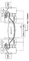
図5に、図2~図4において説明した本発明の実施形態のネットワーク構成を示す。上記のように、SDNコントローラ/NMS100は伝送レイヤ及び転送レイヤを含む系全体を制御する。SDNコントローラ/NMS100は、転送パスの開通要求を受け付け、開通要求において求められた冗長要件を満たす転送パス(VPN)を設定する。
例えば、転送パスの開通要求において転送プロテクションが求められた場合には、伝送リストレーションは必要ないため、伝送リストレーションが設定されていない伝送パス(光波長パスID=2)を利用する。そして、この伝送パス上に、転送レイヤにおいて転送プロテクションが設定された転送パスを開通させる。
例えば、転送パスの開通要求において伝送リストレーションが求められた場合には、伝送リストレーションが設定された伝送パス(光波長パスID=1)を利用する。転送プロテクションは必要ないため、この伝送パス上に、転送レイヤにおいて冗長なしのパスを開通させる。
例えば、転送パスの開通要求において冗長構成の必要がない場合には、伝送リストレーションは必要ないため、伝送リストレーションが設定されていない伝送パス(光波長パスID=2)を利用する。転送プロテクションも必要ないため、この伝送パス上に、転送レイヤにおいて冗長なしのパスを開通させる。
このように、SDNコントローラ/NMS100が転送レイヤの冗長構成だけでなく、伝送レイヤの冗長構成も管理することで、転送パスを構築する際のアンダーレイNWの経路毎に利用可能な伝送レイヤの冗長構成を識別し、転送パスの開通要求の要件に合わせた経路で転送パスを開通させる。上記の例の通り、SDNコントローラ/NMS100は、転送パスに対して複数の冗長構成(転送プロテクション・伝送リストレーション・冗長なし)を設定することが可能になる。
以下、本発明の実施形態について更に詳細に説明する。
<第1実施形態>
第1実施形態では、転送レイヤのパスを構築する際に伝送レイヤの冗長構成を設定する手法について説明する。本実施形態では、図3を参照して説明した通り、伝送装置Aと伝送装置Bの区間において、波長λ1を用いる光波長パスID=1を伝送リストレーション制御対象としており、波長λ2及びλ3を用いる光波長パスID=2, 3を伝送リストレーション制御非対象としていることを前提に説明する。
第1実施形態では、転送レイヤのパスを構築する際に伝送レイヤの冗長構成を設定する手法について説明する。本実施形態では、図3を参照して説明した通り、伝送装置Aと伝送装置Bの区間において、波長λ1を用いる光波長パスID=1を伝送リストレーション制御対象としており、波長λ2及びλ3を用いる光波長パスID=2, 3を伝送リストレーション制御非対象としていることを前提に説明する。
図6に、本発明の第1実施形態に係るSDNコントローラ/NMS100のブロック構成図を示す。SDNコントローラ/NMS100は、機能部としての要求受付部101と、転送パス開通実施部102と、伝送パス開通実施部103と、伝送リストレーション実施部104と、ルータ制御部105と、伝送装置制御部106とを有する。また、SDNコントローラ/NMS100は、記憶部としての転送パス情報DB111と、経路情報DB112と、伝送構成情報DB113と、伝送リストレーション迂回経路情報DB114とを有する。
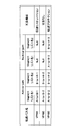
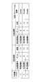
転送パス情報DB111は、ルータ間に設定された転送パス(VPN)と経路(Segmentリスト)と冗長構成との対応を管理する記憶部である。転送パス情報DB111には、以下に説明する転送パス開通実施部102が開通した転送パスの情報が登録される。例えば、図4に示す例においてルータA, B間の経路Adjacency SID=101を利用する伝送リストレーションが設定された転送パスVPN1が開通した場合、転送パス情報DB111は、図7の1行目に示すような情報を保持する。なお、Segment Routingは、片方向ずつ経路を指定するため、双方向通信のサービスの場合は2つの経路で1セットとなり、転送パス情報DB111には双方向通信のサービス毎に2つの経路が保持される。
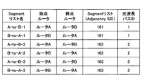
経路情報DB112は、ルータ間に設定された経路(Segmentリスト)と当該経路で用いられる光波長パスとの対応を管理する記憶部である。例えば、図3及び図4に示す例においてAdjacency SID=101が伝送装置A, B間の光波長パスID=1の上に設定されている場合、経路情報DB112は、図8の1行目及び2行目に示すように、始点ルータ、終点ルータ、Segmentリスト、波長パスIDを保持する。この場合においても、Segment Routingは、片方向ずつ経路を指定するため、双方向通信のサービスの場合は2つの経路で1セットとなり、経路情報DB112には双方向の経路が保持される。図8には、Segmentリストに1つのセグメントで構成される場合が示されているが、ルータ間に複数のセグメントが存在する場合には、Segmentリストの中に複数のSIDが入る。
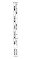
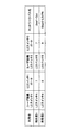
伝送構成情報DB113は、伝送装置間に設定された光波長パスの情報を管理する記憶部である。例えば、伝送構成情報DB113は、図3に示すような物理構成の接続情報を、図9に示すような形式で、光波長パス毎に、両端の伝送装置、ポート、波長、冗長構成(伝送リストレーション制御)の有無を保持する。
伝送リストレーション迂回経路情報DB114は、伝送リストレーション制御の迂回経路情報を管理する記憶部である。例えば、伝送リストレーション迂回経路情報DB114は、図3において説明した、波長λ1の光波長パスID=1を物理ポート5間の迂回経路に迂回させるという迂回経路情報を、図10に示すような形式で保持する。
要求受付部101は、転送パス(VPN)に対する冗長構成の要件(転送プロテクション/伝送リストレーション/冗長なし)を含む開通要求を受け付ける。開通要求には、転送パスの始点・終点も含まれる。これはSDNコントローラ/NMS100の外部からの要求でもよく、SDNコントローラ/NMS100内に予め設定されたアルゴリズムで計算した結果からの要求でもよい。
転送パス開通実施部102は、開通要求に応じて、転送パス開通要求の冗長構成を実現可能な経路を経路情報DB112から検索し、開通要求の冗長構成を実現可能な経路を伝送構成情報DB113から検索する。
転送パス(VPN1)を開通させるときの冗長構成の要件として伝送リストレーションが求められた場合には、転送パス開通実施部102は、伝送リストレーションが設定された伝送パスに紐付く冗長構成のない転送パスを開通させる必要がある。具体的には、転送パス開通実施部102は、初めに伝送構成情報DB113より伝送リストレーションが有効(Enable)の波長(λ1)を検索し、次に伝送リストレーションが有効な波長(λ1)を利用していてかつ、要求された転送パスの始点・終点が一致するSegmentリスト名を経路情報DB112から検索する。利用可能なSegmentリスト名が複数存在する場合には、最短パスを動的に検出してもよいし何らかの重みづけアルゴリズムを利用した動的な決定やオペレータが選択する静的な決定をしてもよい。また、Segment Routingは、片方向ずつ経路を指定するため、双方向通信の場合は2つで1セットとなり、始点から終点と、終点から始点との2経路を抽出する必要がある。このように抽出した情報をもとに図7の1行目に示すような転送パス情報を作成する。伝送リストレーションの場合には転送プロテクションは設定されないため、Backup-pathはNullとする。
転送パス開通実施部102は、転送パス情報DB111に情報を登録するとともに、ルータ制御部105を介して始点・終点のルータに対して転送パス(VPN1)の設定を実施する。ルータへの設定投入方法はNetconf等のオープンAPI(Application Programming Interface)でもよいしルータ独自のプロトコルを利用してもよい。
転送パス(VPN2)を開通させるときの冗長構成の要件として冗長なしが求められた場合には、転送パス開通実施部102は、伝送リストレーションが設定されていない伝送パスに紐付く冗長構成のない転送パスを開通させる必要がある。具体的には、転送パス開通実施部102は、初めに伝送構成情報DB113より伝送リストレーションが無効(Disable)の波長(λ2, λ3)を検索し、次に伝送リストレーションが無効な波長(λ2, λ3)を利用していてかつ、要求された転送パスの始点・終点が一致するSegmentリスト名を経路情報DB112から検索する。利用可能なSegmentリスト名が複数存在する場合には、最短パスを動的に検出してもよいし何らかの重みづけアルゴリズムを利用した動的な決定やオペレータが選択する静的な決定をしてもよい。また、Segment Routingは、片方向ずつ経路を指定するため、双方向通信の場合は2つで1セットとなり、始点から終点と、終点から始点との2経路を抽出する必要がある。このように抽出した情報をもとに図7の2行目に示すような転送パス情報を作成する。冗長なしの場合には転送プロテクションは設定されないため、Backup-pathはNullとする。
転送パス開通実施部102は、転送パス情報DB111に情報を登録するとともに、ルータ制御部105を介して始点・終点のルータに対して転送パス(VPN2)の設定を実施する。
転送パス(VPN3)を開通させるときの冗長構成の要件として転送プロテクションが求められた場合には、転送パス開通実施部102は、伝送リストレーションが設定されていない伝送パスに紐付く冗長構成の転送パスを開通させる必要がある。具体的には、転送パス開通実施部102は、初めに伝送構成情報DB113より伝送リストレーションが無効(Disable)の波長(λ2, λ3)を検索し、次に伝送リストレーションが無効な波長(λ2, λ3)を利用していてかつ、要求された転送パスの始点・終点が一致するSegmentリスト名を経路情報DB112から検索する。この場合、利用可能なSegmentリスト名がActive-PathとBackup-Path用の2経路分が存在していなければならない。2経路以上存在する場合には、最短パスを動的に検出してもよいし何らかの重みづけアルゴリズムを利用した動的な決定やオペレータが選択する静的な決定をしてもよい。決定した2経路のどちらをActive-Pathにするかも同様に決定してもよい。また、Segment Routingは、片方向ずつ経路を指定するため、双方向通信の場合は2つで1セットとなり、始点から終点と、終点から始点との2経路を抽出する必要がある。このように抽出した情報をもとに図7の3行目に示すような転送パス情報を作成する。転送プロテクションの場合にはBackup-pathはActive-Pathに選ばれなかった経路とする。
転送パス開通実施部102は、転送パス情報DB111に情報を登録するとともに、ルータ制御部105を介して始点・終点のルータに対して転送パス(VPN3)の設定を実施する。
なお、転送パス開通実施部102は、伝送構成情報DB113の中に伝送レイヤの冗長構成の要件を満たす伝送パスが存在しない場合、伝送パス開通実施部103に対して、伝送パスの開通を要求する。例えば、転送パス開通実施部102が伝送構成情報DB113から伝送リストレーションが有効の波長を見つけることができなかった場合、転送パス開通実施部102は、伝送パス開通実施部103に対して伝送リストレーションが設定された伝送パスの開通を要求する。
伝送パス開通実施部103は、伝送パスを開通させ、開通させた伝送パスの情報を伝送構成DB113に登録する。伝送パスの冗長構成の要件として伝送リストレーションが求められた場合には、伝送パス開通実施部103は図9の伝送構成情報DB113に情報を登録する際に伝送リストレーション制御を有効(Enable)にした伝送パスを登録する。伝送パスの冗長構成の要件として伝送リストレーションが求められていない場合には、伝送パス開通実施部103は図9の伝送構成情報DB113に情報を登録する際に伝送リストレーション制御を無効(Disable)にした伝送パスを登録する。利用するポートや波長はオペレータが手動で登録してもよいし、その他のリソースプール等の情報から自動的に割り当ててもよい。伝送パス開通実施部103は、伝送構成情報DB113に情報を登録するとともに、伝送装置制御部106を介して伝送装置に設定を投入することで伝送パスを開通させる。伝送装置への設定投入方法はNetconf等のオープンAPIでもよいし伝送装置独自のプロトコルを利用してもよい。
伝送リストレーション実施部104は、伝送装置間で障害が発生して伝送装置からポートダウンのアラートを受けた場合、アラートを受けたポートを利用している波長を伝送構成情報DB113から検索して特定する。例えば、伝送装置Aの物理ポート4と伝送装置Bの物理ポート4との間で障害が発生した場合、伝送構成情報DB113から伝送装置Aの物理ポート4及び伝送装置Bの物理ポート4を利用している波長(λ1, λ2)を抽出する。波長λ2は伝送リストレーション制御が無効(Disable)であるため、迂回経路に迂回されない。伝送リストレーション実施部104は、抽出した波長のリストレーション制御が有効(Enable)な波長(λ1)の光波長パスID=1を抽出し、図10の伝送リストレーション迂回経路情報DB114から迂回経路を検索する。伝送リストレーション実施部104は、その情報をもとに伝送装置制御部106を介して伝送装置を制御して迂回経路で動的に復旧させる。上記の例では、波長λ1の光波長パスを、伝送装置Aの物理ポート5と伝送装置Bの物理ポート5との間の迂回経路に迂回させる。
このようにマルチレイヤ(伝送レイヤ・転送レイヤ)の情報をSDNコントローラ/NMS100が一元的に保持することで、転送レイヤのパスに対して伝送レイヤの冗長構成を設定することが可能となる。特に、ルータ及び伝送装置をSDNコントローラ/NMS100が制御するネットワークにおいて、開通要求に応じて転送パス(L2VPN/L3VPN)を開通させる際に、転送パスの経路となるルータ間のリンクが利用している伝送レイヤの波長パスの冗長構成(伝送リストレーション・冗長なし)の情報をもとに転送パスの経路を決定することで、転送パスの冗長構成として転送レイヤで実現される冗長構成(転送プロテクション・冗長なし)に加えて伝送レイヤで実現される冗長構成(冗長プロテクション)も設定することができる。
<第2実施形態>
第2実施形態では、上記のように、SDNコントローラ/NMS100が伝送レイヤ及び転送レイヤを含む系全体を制御するという概念を応用して、利用者に対してネットワークパス(伝送パス(光波長パス)又は転送パス(VPN))を複数の冗長構成で利用可能にする手法について説明する。
第2実施形態では、上記のように、SDNコントローラ/NMS100が伝送レイヤ及び転送レイヤを含む系全体を制御するという概念を応用して、利用者に対してネットワークパス(伝送パス(光波長パス)又は転送パス(VPN))を複数の冗長構成で利用可能にする手法について説明する。
第2実施形態では、図2のようにルータと伝送装置を直接接続せず、図11に示すようにL2スイッチと利用者・ルータ・伝送装置がそれぞれ接続する構成とする。L2スイッチを利用者とネットワークパスの接続点として用い、パス開通要求に応じたネットワークパスを利用者の接続ポートまで開通する方法を提供する。本実施形態ではネットワークパスの端点をルータ又は伝送装置が接続されているL2スイッチのポートとし、利用者の接続点を同一のL2スイッチのポートとする。
図11に、本発明の第2実施形態におけるIP/伝送ネットワークの構成を示す。図11に示すように、利用者が接続するL2スイッチAとL2スイッチBとの間を接続するために、ルータA, Bと、伝送装置A, Bとが用いられる。なお、図11には、2つのルータと2つの伝送装置が示されているが、IP/伝送ネットワークを構成するために如何なる数のルータ及び伝送装置が用いられてもよい。また、L2スイッチと利用者・ルータ・伝送装置が接続されている構成であれば光ネットワークの接続構成等が変わっても本実施形態は適用できる。
利用者をL2スイッチを介してルータ及び伝送装置に接続することにより、図1の従来のネットワーク構成とは異なり、利用者が同一の端点(L2スイッチ)から、伝送リストレーションを設定した伝送パスを利用可能にするとともに、転送プロテクションを利用した転送パスを利用可能にする。
図12に、本発明の第2実施形態における伝送パスの構成例を示す。SDNコントローラ/NMS100は、伝送パスを開通させるときは、伝送装置Aと伝送装置Bとの間に、伝送レイヤの冗長構成の要件(伝送リストレーション/冗長なし)を満たす伝送パスを開通させる。例えば、伝送リストレーションが求められている場合には、伝送装置Aの物理ポート4と伝送装置Bの物理ポート4との間に、伝送リストレーションが設定された波長λ1を用いる光波長パス(光波長パスID=1)を開通させる。
L2スイッチ及び伝送装置間の物理配線情報・ポート情報はSDNコントローラ/NMS100に登録されているものとする。また、伝送装置内の接続関係も、SDNコントローラ/NMS100に登録されているものとする。すなわち、上記のように波長λ1を用いる光波長パス(光波長パスID=1)を開通させたときに、L2スイッチAのポート5が伝送リストレーションのある光波長パスの端点であることを、SDNコントローラ/NMS100は把握することができる。
SDNコントローラ/NMS100は、伝送パスの冗長構成に応じてネットワーク上に伝送パスを構成するとともに、L2スイッチにおいて利用者の接続ポートと、構成した伝送パスの端点となっているL2スイッチのポートとの対応付けを行う。対応付けの手段は本実施形態ではVLAN(Virtual Local Area Network)を用いる例で説明するが、接続ポートの通信を伝送パスに通すことが可能であれば他の技術を用いた場合でも本実施形態は適用することができる。冗長構成として伝送リストレーションが求められた場合、SDNコントローラ/NMS100は、上記のように光波長パス(光波長パスID=1)を開通させ、伝送パス開通時に利用者の接続ポート(L2スイッチA, Bのポート7)と伝送パスの端点(L2スイッチA, Bのポート5)を同じVLANに所属させる。
図13に、本発明の第2実施形態における転送パスの構成例を示す。SDNコントローラ/NMS100は、転送パスを開通させるときは、伝送装置A, Bを介してルータAとルータBとの間に、転送レイヤの冗長構成の要件(転送プロテクション/冗長なし)を満たす転送パスを開通させる。例えば、冗長構成が求められていない場合には、伝送装置Aの物理ポート5と伝送装置Bの物理ポート5との間に、伝送リストレーションが設定されていない波長λ3を用いる光波長パス(光波長パスID=3)を開通させる。そして、ルータAの物理ポート3とルータBの物理ポート3との間に、L2スイッチA, Bを介して波長λ3を用いる光波長パス上に1経路の転送パス(VPN)を設定する。なお、転送プロテクションが求められており伝送リストレーションが求められていない場合には、同様に伝送リストレーションが設定されていない波長λ3を用いる光波長パス(光波長パスID=3)を開通させ、ルータ間に2経路の転送パスを設定すればよい。
L2スイッチ・ルータ・伝送装置間の物理配線情報・ポート情報はSDNコントローラ/NMS100に登録されているものとする。また、ルータ内の接続関係及び伝送装置内の接続関係も、SDNコントローラ/NMS100に登録されているものとする。すなわち、上記のように冗長構成のない転送パス(VPN)を開通させたときに、L2スイッチAのポート2が冗長構成のない転送パスの端点であることを、SDNコントローラ/NMS100は把握することができる。
SDNコントローラ/NMS100は、転送パスの冗長構成に応じてネットワーク上に転送パスを構成するとともに、L2スイッチにおいて利用者の接続ポートと、構成した転送パスの端点となっているL2スイッチのポートとの対応付けを行う。冗長構成が求められていない場合、SDNコントローラ/NMS100は、上記のように光波長パス(光波長パスID=3)上に1経路の転送パスを開通させ、転送パス開通時に利用者の接続ポート(L2スイッチA, Bのポート8)と転送パスの端点(L2スイッチA, Bのポート2)を同じVLANに所属させる。
図14に、本発明の第2実施形態に係るSDNコントローラ/NMS100のブロック構成図を示す。第1実施形態に加えて、SDNコントローラ/NMS100は、機能部としてのネットワークパス判断実施部107と、L2スイッチ内部開通実施部108と、L2スイッチ制御部109とを更に有する。また、SDNコントローラ/NMS100は、記憶部としての伝送パス情報DB115と、利用者接続情報DB116と、L2スイッチ接続情報DB117とを更に有する。以下、第1実施形態と異なる点について説明する。
伝送パス情報DB115は、利用者の開通要求に応じて設定された伝送パスを管理する記憶部である。伝送パス情報DB115には、以下に説明する伝送パス開通実施部103が開通した伝送パスの端点の情報が登録される。例えば、図12に示す例においてL2スイッチA, B間に伝送装置A, B間の伝送リストレーションが設定された伝送パスが開通した場合、伝送パス情報DB115は、図15に示すような情報を保持する。
利用者接続情報DB116は、利用者の開通要求に応じて設定されたネットワークパス(伝送パス及び転送パス)の利用者側の接続情報を管理する記憶部である。利用者接続情報DB116には、以下に説明する伝送パス開通実施部103及び転送パス開通実施部102が開通した伝送パス及び転送パスについて、図16に示すような形式でL2スイッチの利用者側のポートの情報を保持する。
L2スイッチ接続情報DB117は、L2スイッチ内に設定されたVLANの情報を管理する記憶部である。L2スイッチ接続情報DB117には、以下に説明するL2スイッチ内部開通実施部108が開通したL2スイッチ内のVLANの情報を、図17に示すような形式で保持する。
要求受付部101は、利用者からネットワークパスに対する冗長構成の要件(転送プロテクション/伝送リストレーション/冗長なし)を含む開通要求を受け付ける。これはSDNコントローラ/NMS100の外部からの要求でもよく、SDNコントローラ/NMS100内に予め設定されたアルゴリズムで計算した結果からの要求でもよい。開通要求には、利用者の接続点及びネットワークパスを構築するために必要な条件(冗長構成)が含まれているものとする。
ネットワークパス判断実施部107は、要求されたネットワークパスが伝送パスか転送パスを判断する。転送パスである場合には転送パス開通実施部102に転送パスを開通させるための転送パス開通要求を行う。伝送パスである場合には伝送パス開通実施部103に伝送パスを開通させるための伝送パス開通要求を行う。冗長構成の要件として転送プロテクションが求められた場合には、ネットワークパス判断実施部107は、転送パス開通実施部102に対して転送プロテクションを設定した転送パスを開通させるための要求を行う必要がある。冗長構成の要件として冗長リストレーションが求められた場合には、ネットワークパス判断実施部107は、伝送パス開通実施部103に対して冗長リストレーションを設定した伝送パスを開通させるための要求を行う必要がある。
転送パス開通実施部102は、転送パス開通要求に応じて転送パス情報を生成し、第1実施形態と同様に転送パス情報DB111に情報を登録するとともに、利用者接続情報DB116に情報を登録する。構築可能な転送パス情報の生成はSDNコントローラ/NMS100内のアルゴリズムで計算してもよいし、外部から与えられてもよい。例えば、利用者2から冗長なしの転送パスが求められた場合、図13に示すように、伝送装置A, Bを介して(光波長パス(光波長パスID=3)上に)、ルータA, B間に1経路の転送パスを開通させる。なお、転送プロテクションが設定された転送パスが求められた場合には、ルータA, B間に2経路の転送パスを開通させる。
転送パスの開通に際し、転送パス開通実施部102は、転送パス情報DB111に加えて利用者接続情報DB116に情報を登録するとともに、ルータ制御部105を介して始点・終点のルータに対して転送パスの設定を実施する。ルータへの設定投入方法はNetconf等のオープンAPIでもよいしルータ独自のプロトコルを利用してもよい。
伝送パス開通実施部103は、伝送パス開通要求に応じて伝送パス情報を生成し、第1実施形態と同様に伝送構成情報DB113に情報を登録するとともに、伝送パス情報DB115及び利用者接続情報DB116に情報を登録する。構築可能な伝送パス情報の生成はSDNコントローラ/NMS100内のアルゴリズムで計算してもよいし、外部から与えられてもよい。例えば、利用者1から伝送リストレーションが設定された伝送パスが求められた場合、図12に示すように、伝送装置A, Bの物理ポート4の間に伝送リストレーションが設定された伝送パスを開通させる。
伝送パスの開通に際し、伝送パス開通実施部103は、伝送構成情報DB113に加えて伝送パス情報DB115及び利用者接続情報DB116に情報を登録するとともに、伝送装置制御部106を介して伝送装置に設定を投入することで伝送パスを開通させる。伝送装置への設定投入方法はNetconf等のオープンAPIでもよいし伝送装置独自のプロトコルを利用してもよい。
L2スイッチ内部開通実施部108は、利用者が接続する始点・終点のL2スイッチにおいて、開通したネットワークパス(転送パス又は転送パス)の端点であるL2スイッチのポートと利用者の接続点とを接続させる。具体的には、L2スイッチ内部開通実施部108は、転送パス開通実施部102又は伝送パス開通実施部103が構築したネットワークパスにそれぞれ紐づくL2スイッチの利用者接続ポート情報とネットワークパス端点のポート情報を利用者接続情報DB116又は伝送パス情報DB115から取得し、L2スイッチ接続情報DB117に情報を登録する。L2スイッチ接続情報DBのVLAN情報(VLAN1, VLAN2)はコントローラが空いてるVLAN番号から自動的に設定してもよいし、静的に設定してもよい。L2スイッチ内部開通実施部108は、L2スイッチ接続情報DB117に登録された情報をもとに、L2スイッチ制御部109を介して利用者の接続ポートとネットワークパスの端点のそれぞれのL2スイッチのポート間の通信が可能なようにする。L2スイッチのポート間の開通方法はVLANに限定されず、ルーティングやVXLAN(Virtual eXtensible Local Area Network)等を利用してもよい。L2スイッチへの設定投入方法はNetconf等のオープンAPIでもよいしL2スイッチ独自のプロトコルを利用してもよい。
このように、L2スイッチを利用した通信ネットワークにおいて、伝送パス(波長占有専用線)と転送パス(L2VPN/L3VPN)の端点を同一のL2スイッチに収容し、利用者の接続点も同一のL2スイッチとしたうえで、転送パス又は伝送パスの端点で利用しているL2スイッチのポートと利用者の接続点のL2スイッチのポートを通信可能になるようにコントローラが制御することで、多様な条件の伝送パスと転送パスを同一の接続点で提供することができる。
<第3実施形態>
第3実施形態では、第1実施形態及び第2実施形態において、伝送リストレーションの通信断を短くするために、伝送リストレーションを行っている間に、対象の波長を利用している転送パス又は伝送パスのトラフィックを一時的に開通済みの転送パス又は伝送パスに収容し、伝送リストレーションが完了した後に、伝送リストレーションによって復旧可能な迂回経路にトラフィックを収容し直す手法について説明する。
第3実施形態では、第1実施形態及び第2実施形態において、伝送リストレーションの通信断を短くするために、伝送リストレーションを行っている間に、対象の波長を利用している転送パス又は伝送パスのトラフィックを一時的に開通済みの転送パス又は伝送パスに収容し、伝送リストレーションが完了した後に、伝送リストレーションによって復旧可能な迂回経路にトラフィックを収容し直す手法について説明する。
伝送リストレーションは伝送パスの障害時に伝送装置による波長の方路切替によって伝送パスを復旧する技術であるが、伝送装置の制御には一般的にある程度の時間がかかるため、復旧までの通信断時間が転送プロテクションに比べて長くなる。伝送装置による波長の方路切替が完了するまでの間、一時的に開通済みの転送パス又は伝送パスに利用者のトラフィックを収容し、波長の方路切替が完了した後に、方路切替後の伝送パスに利用者のトラフィックを収容しなおすことで伝送リストレーションの通信断時間を短くすることが可能となる。以下の説明において、一時的に利用する開通済みの転送パス又は伝送パスを一時迂回パスと呼び、方路切替後の伝送パスを迂回パスと呼ぶ。
一時迂回パスはこの用途のための専用パスとして開通しておいてもよいし、既存の他利用者が利用しているパスを共用してもよいものとする。一時迂回パスの決定方法は伝送リストレーション対象の伝送パスの契約帯域から利用可能なパスを選定してもよいし、別のロジックで選定してもよい。
第3実施形態のSDNコントローラ/NMS100のブロック構成図は、図6に示す第1実施形態のブロック構成図又は図14に示す第2実施形態のブロック構成図と同じである。
まず、図6に示す第1実施形態のブロック構成図を参照して、第3実施形態のSDNコントローラ/NMS100の機能部における処理を説明する。
伝送リストレーション実施部104は、伝送装置間で障害が発生して伝送装置からポートダウンのアラートを受けた場合、アラートを受けたポートを利用している波長を伝送構成情報DB113から検索して特定する。例えば、伝送装置Aの物理ポート4と伝送装置Bの物理ポート4との間で障害が発生した場合、伝送構成情報DB113から伝送装置Aの物理ポート4及び伝送装置Bの物理ポート4を利用している波長(λ1, λ2)を抽出する。波長λ2は伝送リストレーション制御が無効(Disable)であるため、迂回パスに迂回されない。伝送リストレーション実施部104は、抽出した波長のリストレーション制御が有効(Enable)な波長(λ1)の光波長パスID=1を抽出する。また、経路情報DB112から光波長パスID=1によって影響を受けるSegmentリスト(A-to-B-1及びB-to-A-1)を抽出し、そのSegmentリストを利用する転送パス(VPN1)を抽出する。光波長パスID=1と始点・終点が一致する別の開通済みの光波長パスが存在する場合、伝送リストレーション実施部104は、その開通済みの光波長パスを、光波長パスID=1の一時迂回パスとして利用する。また、転送パス(VPN1)と始点・終点が一致する別の開通済みの転送パスが存在する場合、伝送リストレーション実施部104は、その開通済みの転送パスを、転送パス(VPN1)の一時迂回パスとして利用してもよい。伝送リストレーション実施部104は、光波長パスID=1の波長の方路切替が完了するまで、影響を受ける転送パス又は伝送パスを一時迂回パスに迂回させる。その後、伝送リストレーション実施部104は、図10の伝送リストレーション迂回経路情報DB114から迂回パスを検索する。伝送リストレーション実施部104は、その情報をもとに伝送装置制御部106を介して伝送装置を制御して迂回パスへの波長の方路切替を実施する。迂回パスへの波長の方路切替が完了した後に、伝送リストレーション実施部104は一時迂回パスのトラフィックを波長の方路切替が完了した迂回パスに収容し直す。
次に、図14に示す第2実施形態のブロック構成図を参照して、第3実施形態のSDNコントローラ/NMS100の機能部における処理を説明する。
伝送リストレーション実施部104は、伝送装置間で障害が発生して伝送装置からポートダウンのアラートを受けた場合、上記のようにアラートによって影響を受ける転送パス又は転送パスを特定する。特定した転送パス又は伝送パスの波長のリストレーション制御が有効(Enable)である場合、波長の方路切替が完了するまで、影響を受ける転送パス又は伝送パスを一時迂回パスに迂回させ、波長の方路切替が完了した後に、一時迂回パスを迂回パスに迂回させる。
L2スイッチ内部開通実施部108は、上記のように伝送リストレーション実施部104において転送パス又は伝送パスを一時迂回パスに迂回させる場合、一時迂回パスの端点と利用者の接続点とを接続させる。具体的には、伝送リストレーション実施部104が伝送リストレーション対象となっている転送パス又は伝送パスを迂回させる一時迂回パスを選定したとき、その転送パス又は伝送パスの端点となっているL2スイッチのポートをL2スイッチ接続情報DB117を参照して特定する。また、一時迂回パスの端点となっているL2スイッチのポートも、L2スイッチ接続情報DB117を参照して特定する。L2スイッチ内部開通実施部108は、一時迂回パスの端点となっているL2スイッチのポートと利用者の接続ポートとを接続させる。
さらに、L2スイッチ内部開通実施部108は、上記のように伝送リストレーション実施部104において一時迂回パスを迂回パスに迂回させる場合、迂回パスの端点と利用者の接続点とを接続させる。具体的には、伝送リストレーション実施部104が伝送リストレーション対象となっている伝送パスの迂回パスを選定したとき、その迂回パスの端点となっているL2スイッチのポートをL2スイッチ接続情報DB117を参照して特定する。L2スイッチ内部開通実施部108は、利用者の接続ポートと接続している一時迂回パスの端点となっているL2スイッチのポートを、迂回パスの端点となっているL2スイッチのポートに紐付け直す。
<ハードウェア構成例>
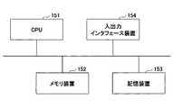
図18に、本発明の実施形態に係るSDNコントローラ/NMS100のハードウェア構成例を示す。SDNコントローラ/NMS100は、CPU(Central Processing Unit)151等のプロセッサ、RAM(Random Access Memory)やROM(Read Only Memory)等のメモリ装置152、ハードディスク等の記憶装置153等から構成されたコンピュータでもよい。例えば、SDNコントローラ/NMS100の機能及び処理は、記憶装置153又はメモリ装置152に格納されているデータやプログラムをCPU151が実行することによって実現される。また、SDNコントローラ/NMS100へのデータの入力は、入出力インタフェース装置154から行われ、SDNコントローラ/NMS100からのデータの出力は、入出力インタフェース装置154から行われてもよい。
図18に、本発明の実施形態に係るSDNコントローラ/NMS100のハードウェア構成例を示す。SDNコントローラ/NMS100は、CPU(Central Processing Unit)151等のプロセッサ、RAM(Random Access Memory)やROM(Read Only Memory)等のメモリ装置152、ハードディスク等の記憶装置153等から構成されたコンピュータでもよい。例えば、SDNコントローラ/NMS100の機能及び処理は、記憶装置153又はメモリ装置152に格納されているデータやプログラムをCPU151が実行することによって実現される。また、SDNコントローラ/NMS100へのデータの入力は、入出力インタフェース装置154から行われ、SDNコントローラ/NMS100からのデータの出力は、入出力インタフェース装置154から行われてもよい。
<補足>
説明の便宜上、本発明の実施形態に係る装置は機能的なブロック図を用いて説明しているが、本発明の実施形態に係る装置は、ハードウェア、ソフトウェア又はそれらの組み合わせで実現されてもよい。例えば、本発明の実施形態は、コンピュータに対して本発明の実施形態に係る装置の機能を実現させるプログラム、コンピュータに対して本発明の実施形態に係る方法の各手順を実行させるプログラム等により、実現されてもよい。また、各機能部が必要に応じて組み合わせて使用されてもよい。また、本発明の実施形態に係る方法は、実施形態に示す順序と異なる順序で実施されてもよい。
説明の便宜上、本発明の実施形態に係る装置は機能的なブロック図を用いて説明しているが、本発明の実施形態に係る装置は、ハードウェア、ソフトウェア又はそれらの組み合わせで実現されてもよい。例えば、本発明の実施形態は、コンピュータに対して本発明の実施形態に係る装置の機能を実現させるプログラム、コンピュータに対して本発明の実施形態に係る方法の各手順を実行させるプログラム等により、実現されてもよい。また、各機能部が必要に応じて組み合わせて使用されてもよい。また、本発明の実施形態に係る方法は、実施形態に示す順序と異なる順序で実施されてもよい。
以上、転送レイヤの転送パスに対して伝送レイヤの冗長構成を適用可能にすることで、より多くの信頼性の要件を満たす転送パスを提供するための手法について説明したが、本発明は、上記の実施形態に限定されることなく、特許請求の範囲内において、種々の変更・応用が可能である。
100 SDNコントローラ/NMS
101 要求受付部
102 転送パス開通実施部
103 伝送パス開通実施部
104 伝送リストレーション実施部
105 ルータ制御部
106 伝送装置制御部
107 ネットワークパス判断実施部
108 L2スイッチ内部開通実施部
109 L2スイッチ制御部
111 転送パス情報DB
112 経路情報DB
113 伝送構成情報DB
114 伝送リストレーション迂回経路情報DB
115 伝送パス情報DB
116 利用者接続情報DB
117 L2スイッチ接続情報DB
101 要求受付部
102 転送パス開通実施部
103 伝送パス開通実施部
104 伝送リストレーション実施部
105 ルータ制御部
106 伝送装置制御部
107 ネットワークパス判断実施部
108 L2スイッチ内部開通実施部
109 L2スイッチ制御部
111 転送パス情報DB
112 経路情報DB
113 伝送構成情報DB
114 伝送リストレーション迂回経路情報DB
115 伝送パス情報DB
116 利用者接続情報DB
117 L2スイッチ接続情報DB
Claims (6)
- 複数のルータと、当該複数のルータ間を接続するための複数の伝送装置とで構成される通信ネットワークにおいて用いられる制御装置であって、
伝送装置間を接続する伝送パスと、当該伝送パスに対して伝送レイヤにおける冗長構成が利用可能であるか否かを管理する伝送構成情報記憶部と、
ルータ間に設定された経路と、当該経路で用いられる伝送パスとを管理する経路情報記憶部と、
ルータ間を接続する転送パスに対する冗長構成の要件を含む開通要求に応じて、前記伝送構成情報記憶部及び前記経路情報記憶部を参照して、当該冗長構成の要件として転送レイヤにおける冗長構成が求められた場合には、冗長の経路を利用する転送パスを開通させ、当該冗長構成の要件として伝送レイヤにおける冗長構成が求められた場合には、伝送レイヤにおける冗長構成の伝送パスに紐付く、冗長の経路を利用しない転送パスを開通させる転送パス開通実施部と、
を有する制御装置。 - 伝送装置間を接続する伝送パスを開通させ、当該伝送パスに対して伝送レイヤにおける冗長構成が利用可能であるか否かを前記伝送構成情報記憶部に登録する伝送パス開通実施部
を更に有する、請求項1に記載の制御装置。 - 伝送装置からアラートを受信した場合、当該アラートによって影響を受ける転送パス又は伝送パスを特定し、前記転送パス又は前記伝送パスに対して伝送レイヤにおける冗長構成が利用可能である場合、前記転送パス又は前記伝送パスの伝送レイヤにおける迂回パスへの迂回処理が完了するまで、前記転送パス又は前記伝送パスを一時迂回パスに迂回させ、前記転送パス又は前記伝送パスの前記迂回パスへの迂回処理が完了した後に、前記一時迂回パスを前記迂回パスに迂回させる迂回実施部
を更に有する、請求項1又は2に記載の制御装置。 - 前記通信ネットワークは、利用者が接続する始点レイヤ2スイッチ及び終点レイヤ2スイッチを更に有し、
前記始点レイヤ2スイッチ及び前記終点レイヤ2スイッチは、前記複数のルータのいずれか及び前記複数の伝送装置のいずれかに接続され、
当該制御装置は、
前記利用者からの冗長構成の要件を含む開通要求に応じて、当該冗長構成の要件として転送レイヤにおける冗長構成が求められた場合には、前記転送パス開通実施部に対して転送レイヤにおける冗長構成の転送パスを開通させるための開通要求を行い、当該冗長構成の要件として伝送レイヤにおける冗長構成が求められた場合には、前記伝送パス開通実施部に対して伝送レイヤにおける冗長構成の伝送パスを開通させるための開通要求を行うネットワークパス判断実施部と、
前記始点レイヤ2スイッチ及び前記終点レイヤ2スイッチにおいて、開通した転送パス又は伝送パスの端点と前記利用者の接続点とを接続させるレイヤ2スイッチ内部開通実施部と、
を更に有する、請求項2に記載の制御装置。 - 伝送装置からアラートを受信した場合、当該アラートによって影響を受ける転送パス又は伝送パスを特定し、前記転送パス又は前記伝送パスに対して伝送レイヤにおける冗長構成が利用可能である場合、前記転送パス又は前記伝送パスの伝送レイヤにおける迂回パスへの迂回処理が完了するまで、前記転送パス又は前記伝送パスを一時迂回パスに迂回させ、前記転送パス又は前記伝送パスの前記迂回パスへの迂回処理が完了した後に、前記一時迂回パスを前記迂回パスに迂回させる迂回実施部
を更に有し、
前記レイヤ2スイッチ内部開通実施部は、前記転送パス又は前記伝送パスを前記一時迂回パスに迂回させる場合、前記一時迂回パスの端点と前記利用者の接続点とを接続させ、前記一時迂回パスを前記迂回パスに迂回させる場合、前記迂回パスの端点と前記利用者の接続点とを接続させる、請求項4に記載の制御装置。 - 複数のルータと、当該複数のルータ間を接続するための複数の伝送装置とで構成される通信ネットワークにおいて用いられる制御装置が実施する制御方法であって、
伝送装置間を接続する伝送パスと、当該伝送パスに対して伝送レイヤにおける冗長構成が利用可能であるか否かを伝送構成情報記憶部において管理するステップと、
ルータ間に設定された経路と、当該経路で用いられる伝送パスとを経路情報記憶部において管理するステップと、
ルータ間を接続する転送パスに対する冗長構成の要件を含む開通要求に応じて、前記伝送構成情報記憶部及び前記経路情報記憶部を参照して、当該冗長構成の要件として転送レイヤにおける冗長構成が求められた場合には、冗長の経路を利用する転送パスを開通させ、当該冗長構成の要件として伝送レイヤにおける冗長構成が求められた場合には、伝送レイヤにおける冗長構成の伝送パスに紐付く、冗長の経路を利用しない転送パスを開通させるステップと、
を有する制御方法。
Priority Applications (1)
| Application Number | Priority Date | Filing Date | Title |
|---|---|---|---|
| US17/426,758 US20220103464A1 (en) | 2019-01-29 | 2020-01-22 | Control apparatus and control method |
Applications Claiming Priority (2)
| Application Number | Priority Date | Filing Date | Title |
|---|---|---|---|
| JP2019-013660 | 2019-01-29 | ||
| JP2019013660A JP7028200B2 (ja) | 2019-01-29 | 2019-01-29 | 制御装置及び制御方法 |
Publications (1)
| Publication Number | Publication Date |
|---|---|
| WO2020158533A1 true WO2020158533A1 (ja) | 2020-08-06 |
Family
ID=71840962
Family Applications (1)
| Application Number | Title | Priority Date | Filing Date |
|---|---|---|---|
| PCT/JP2020/002080 Ceased WO2020158533A1 (ja) | 2019-01-29 | 2020-01-22 | 制御装置及び制御方法 |
Country Status (3)
| Country | Link |
|---|---|
| US (1) | US20220103464A1 (ja) |
| JP (1) | JP7028200B2 (ja) |
| WO (1) | WO2020158533A1 (ja) |
Families Citing this family (2)
| Publication number | Priority date | Publication date | Assignee | Title |
|---|---|---|---|---|
| JP7810274B2 (ja) * | 2022-08-22 | 2026-02-03 | Ntt株式会社 | コンフィグ投入装置、コンフィグ投入方法、及びコンフィグ投入プログラム |
| WO2024247130A1 (ja) * | 2023-05-30 | 2024-12-05 | 日本電信電話株式会社 | 転送パス構築装置、転送パス構築方法、及びプログラム |
Citations (3)
| Publication number | Priority date | Publication date | Assignee | Title |
|---|---|---|---|---|
| JP2016103689A (ja) * | 2014-11-27 | 2016-06-02 | 三菱電機株式会社 | 光伝送システム、管理装置、光伝送ノード及び光伝送方法 |
| WO2016103632A1 (ja) * | 2014-12-24 | 2016-06-30 | 日本電気株式会社 | マルチレイヤネットワークシステムおよびマルチレイヤネットワークにおけるパス設定方法 |
| JP2019004235A (ja) * | 2017-06-13 | 2019-01-10 | 日本電信電話株式会社 | マルチレイヤ迂回経路制御装置及び迂回経路制御方法 |
Family Cites Families (3)
| Publication number | Priority date | Publication date | Assignee | Title |
|---|---|---|---|---|
| US8849115B2 (en) * | 2008-03-11 | 2014-09-30 | Ciena Corporation | Directionless optical architecture and highly available network and photonic resilience methods |
| JP6342823B2 (ja) * | 2015-01-21 | 2018-06-13 | 日本電信電話株式会社 | ネットワーク管理装置及びネットワーク管理方法 |
| JP6886624B2 (ja) * | 2016-03-30 | 2021-06-16 | 日本電気株式会社 | ネットワークシステム、ネットワーク制御装置、方法およびプログラム |
-
2019
- 2019-01-29 JP JP2019013660A patent/JP7028200B2/ja active Active
-
2020
- 2020-01-22 WO PCT/JP2020/002080 patent/WO2020158533A1/ja not_active Ceased
- 2020-01-22 US US17/426,758 patent/US20220103464A1/en not_active Abandoned
Patent Citations (3)
| Publication number | Priority date | Publication date | Assignee | Title |
|---|---|---|---|---|
| JP2016103689A (ja) * | 2014-11-27 | 2016-06-02 | 三菱電機株式会社 | 光伝送システム、管理装置、光伝送ノード及び光伝送方法 |
| WO2016103632A1 (ja) * | 2014-12-24 | 2016-06-30 | 日本電気株式会社 | マルチレイヤネットワークシステムおよびマルチレイヤネットワークにおけるパス設定方法 |
| JP2019004235A (ja) * | 2017-06-13 | 2019-01-10 | 日本電信電話株式会社 | マルチレイヤ迂回経路制御装置及び迂回経路制御方法 |
Non-Patent Citations (1)
| Title |
|---|
| TOJO, TAKUYA ET AL: "Multi-layer SDNcontrol technology that controls Integratedly Ip layer and transmission layer", NTT TECHNICAL JOURNAL, vol. 30, no. 5, 1 May 2018 (2018-05-01), pages 47 - 50, ISSN: 0915-2318 * |
Also Published As
| Publication number | Publication date |
|---|---|
| JP7028200B2 (ja) | 2022-03-02 |
| JP2020123792A (ja) | 2020-08-13 |
| US20220103464A1 (en) | 2022-03-31 |
Similar Documents
| Publication | Publication Date | Title |
|---|---|---|
| KR102812234B1 (ko) | 세분화된 네트워크 엘리먼트를 포함하는 로직 라우터 | |
| KR101460848B1 (ko) | 가상 스위치를 구현 및 관리하는 방법 및 장치 | |
| RU2530338C2 (ru) | Предварительно подготовленное сопряжение на основе состояния линий связи поставщиков (plsb) с маршрутизируемым резервированием | |
| EP3820089B1 (en) | Controller provided protection paths | |
| JP6008801B2 (ja) | 伝送システム、送信方法、及び伝送装置 | |
| EP3654664B1 (en) | Method for interconnected ring protection, computer-readable storage medium and computer program product | |
| CN104518963A (zh) | 用于经由交换结构在边缘设备之间实施连接的方法和装置 | |
| CN103684953A (zh) | 避免多连接到vpls传输网的以太网环路中流量损失方法、装置 | |
| WO2015079616A1 (ja) | 通信システム、通信方法、ネットワーク情報結合装置およびネットワーク情報結合プログラム | |
| CN111226422A (zh) | 分组和光融合 | |
| George et al. | A brief overview of vxlan evpn | |
| JP7028200B2 (ja) | 制御装置及び制御方法 | |
| CN100502528C (zh) | 实现自动交换光网络中光连接间的关联的方法 | |
| JP2022533224A (ja) | ネットワーク制御方法、装置、およびシステム | |
| López-Rodríguez et al. | A robust SDN network architecture for service providers | |
| JP5063726B2 (ja) | 仮想ノード装置のコンフィグ制御方法 | |
| WO2015093478A1 (ja) | ネットワークシステム、制御装置、制御方法およびプログラム | |
| US11509398B2 (en) | Control apparatus and control method | |
| US9762446B2 (en) | Methods for dynamic service deployment for virtual/physical multiple device integration | |
| JP2017085442A (ja) | 制御装置、通信システム、制御方法、および、プログラム | |
| KR100431207B1 (ko) | 엠피엘에스(mpls)기반망에서의 엑스트라넷아이피-브이피엔(ip-vpn)서비스 제공 방법 | |
| WO2016152701A1 (ja) | 制御装置、通信システム、制御方法、および、プログラム | |
| US7990945B1 (en) | Method and apparatus for provisioning a label switched path across two or more networks | |
| CN120856650B (zh) | 网络限速方法、装置、设备、存储介质及计算机程序产品 | |
| JP7419927B2 (ja) | 制御装置、制御方法及び制御プログラム |
Legal Events
| Date | Code | Title | Description |
|---|---|---|---|
| 121 | Ep: the epo has been informed by wipo that ep was designated in this application |
Ref document number: 20749149 Country of ref document: EP Kind code of ref document: A1 |
|
| NENP | Non-entry into the national phase |
Ref country code: DE |
|
| 122 | Ep: pct application non-entry in european phase |
Ref document number: 20749149 Country of ref document: EP Kind code of ref document: A1 |