WO2020153315A1 - 作業機械のシステム及び方法 - Google Patents
作業機械のシステム及び方法 Download PDFInfo
- Publication number
- WO2020153315A1 WO2020153315A1 PCT/JP2020/001775 JP2020001775W WO2020153315A1 WO 2020153315 A1 WO2020153315 A1 WO 2020153315A1 JP 2020001775 W JP2020001775 W JP 2020001775W WO 2020153315 A1 WO2020153315 A1 WO 2020153315A1
- Authority
- WO
- WIPO (PCT)
- Prior art keywords
- image
- work machine
- traveling state
- viewpoint
- traveling
- Prior art date
- Legal status (The legal status is an assumption and is not a legal conclusion. Google has not performed a legal analysis and makes no representation as to the accuracy of the status listed.)
- Ceased
Links
Images








Classifications
-
- E—FIXED CONSTRUCTIONS
- E02—HYDRAULIC ENGINEERING; FOUNDATIONS; SOIL SHIFTING
- E02F—DREDGING; SOIL-SHIFTING
- E02F9/00—Component parts of dredgers or soil-shifting machines, not restricted to one of the kinds covered by groups E02F3/00 - E02F7/00
- E02F9/26—Indicating devices
- E02F9/261—Surveying the work-site to be treated
-
- B—PERFORMING OPERATIONS; TRANSPORTING
- B60—VEHICLES IN GENERAL
- B60R—VEHICLES, VEHICLE FITTINGS, OR VEHICLE PARTS, NOT OTHERWISE PROVIDED FOR
- B60R1/00—Optical viewing arrangements; Real-time viewing arrangements for drivers or passengers using optical image capturing systems, e.g. cameras or video systems specially adapted for use in or on vehicles
- B60R1/20—Real-time viewing arrangements for drivers or passengers using optical image capturing systems, e.g. cameras or video systems specially adapted for use in or on vehicles
- B60R1/22—Real-time viewing arrangements for drivers or passengers using optical image capturing systems, e.g. cameras or video systems specially adapted for use in or on vehicles for viewing an area outside the vehicle, e.g. the exterior of the vehicle
- B60R1/28—Real-time viewing arrangements for drivers or passengers using optical image capturing systems, e.g. cameras or video systems specially adapted for use in or on vehicles for viewing an area outside the vehicle, e.g. the exterior of the vehicle with an adjustable field of view
-
- B—PERFORMING OPERATIONS; TRANSPORTING
- B60—VEHICLES IN GENERAL
- B60R—VEHICLES, VEHICLE FITTINGS, OR VEHICLE PARTS, NOT OTHERWISE PROVIDED FOR
- B60R11/00—Arrangements for holding or mounting articles, not otherwise provided for
- B60R11/04—Mounting of cameras operative during drive; Arrangement of controls thereof relative to the vehicle
-
- E—FIXED CONSTRUCTIONS
- E02—HYDRAULIC ENGINEERING; FOUNDATIONS; SOIL SHIFTING
- E02F—DREDGING; SOIL-SHIFTING
- E02F9/00—Component parts of dredgers or soil-shifting machines, not restricted to one of the kinds covered by groups E02F3/00 - E02F7/00
- E02F9/26—Indicating devices
- E02F9/264—Sensors and their calibration for indicating the position of the work tool
-
- G—PHYSICS
- G06—COMPUTING OR CALCULATING; COUNTING
- G06T—IMAGE DATA PROCESSING OR GENERATION, IN GENERAL
- G06T1/00—General purpose image data processing
-
- H—ELECTRICITY
- H04—ELECTRIC COMMUNICATION TECHNIQUE
- H04N—PICTORIAL COMMUNICATION, e.g. TELEVISION
- H04N7/00—Television systems
- H04N7/18—Closed-circuit television [CCTV] systems, i.e. systems in which the video signal is not broadcast
-
- E—FIXED CONSTRUCTIONS
- E02—HYDRAULIC ENGINEERING; FOUNDATIONS; SOIL SHIFTING
- E02F—DREDGING; SOIL-SHIFTING
- E02F3/00—Dredgers; Soil-shifting machines
- E02F3/04—Dredgers; Soil-shifting machines mechanically-driven
- E02F3/76—Graders, bulldozers, or the like with scraper plates or ploughshare-like elements; Levelling scarifying devices
- E02F3/7604—Combinations of scraper blades with soil loosening tools working independently of scraper blades
Definitions
- the present disclosure relates to a work machine system and method.
- the system includes a plurality of cameras attached to a work machine and a controller.
- a plurality of cameras capture images of the work machine and its surroundings.
- the controller synthesizes an overhead image from images captured by a plurality of cameras.
- the controller synthesizes a plurality of images captured by the camera to generate an image showing the work machine and its surroundings. Therefore, the controller can generate images from various viewpoints.
- the user may desire to change to an image with a different viewpoint depending on the running state of the work machine.
- the viewpoint of the image is changed by the manual operation of the user, changing the viewpoint during work is complicated.
- An object of the present disclosure is to allow a user to easily use an image from a viewpoint according to a traveling state of a work machine.
- the system includes a work machine, a plurality of cameras, a processor, and a display.
- the work machine includes a work machine.
- the plurality of cameras capture images showing the periphery of the work machine.
- the processor acquires image data indicating images captured by a plurality of cameras.
- the processor acquires the running state of the work machine.
- a processor synthesize
- the display displays an image from the viewpoint according to the traveling state based on the signal from the processor.
- the method according to the second aspect is a method executed by the processor to display the periphery of the work machine including the work machine on the display.
- the method includes the following processes.
- the first process is to take an image showing the periphery of the work machine with a plurality of cameras.
- the second process is to acquire image data indicating images captured by a plurality of cameras.
- the third process is to acquire the running state of the work machine.
- the fourth processing is to combine the images to generate an image from the viewpoint according to the running state.
- the fifth process is to display an image from the viewpoint according to the traveling state on the display.
- the system includes a processor and a display.
- the processor acquires image data.
- the image data indicates an image showing the periphery of the work machine.
- the processor acquires a traveling state of the work machine, synthesizes the images, and generates an image from a viewpoint according to the traveling state.
- the display displays an image from the viewpoint according to the traveling state based on the signal from the processor.
- the running state of the work machine is acquired. Then, an image from a viewpoint corresponding to the running state is generated and automatically displayed on the display. Therefore, the user can easily use the image from the viewpoint according to the traveling state of the work machine.
- the figure which shows an example of the image at the time of turning left The figure which shows an example of the image at the time of traveling uphill.
- the figure which shows an example of the image at the time of boarding traveling The figure which shows an example of the image in a shoe slip state. It is a figure which shows the structure of the system which concerns on a modification.
- FIG. 1 is a side view showing a work machine 1 according to the embodiment.
- the work machine 1 is a bulldozer.
- the work machine 1 includes a vehicle body 2, a work machine 3, and a traveling device 4.
- the vehicle body 2 includes an engine room 11.
- a driver's cab 12 is arranged behind the engine compartment 11.
- a ripper device 5 is attached to the rear portion of the vehicle body 2.
- the traveling device 4 is a device for traveling the work machine 1.
- the traveling device 4 includes a pair of crawler belts 13 arranged on the left and right sides of the vehicle body 2.
- the work machine 1 runs by driving the crawler belt 13.
- the work machine 3 is arranged in front of the vehicle body 2.
- the work machine 3 is used for work such as excavation, soil transportation, or leveling.
- the work machine 3 includes a blade 14, a lift cylinder 15, a tilt cylinder 16, and an arm 17.
- the blade 14 is supported by the vehicle body 2 via an arm 17.
- the blade 14 is provided so as to be vertically movable.
- the lift cylinder 15 and the tilt cylinder 16 are driven by hydraulic oil discharged from a hydraulic pump 22 described later to change the attitude of the blade 14.
- FIG. 2 is a block diagram showing the configuration of a system 100 for controlling the work machine 1.
- the work machine 1 includes an engine 21, a hydraulic pump 22, a power transmission device 23, and a control valve 24.
- the engine 21, the hydraulic pump 22, and the power transmission device 23 are arranged in the engine compartment 11.
- the hydraulic pump 22 is driven by the engine 21 and discharges hydraulic oil.
- the hydraulic oil discharged from the hydraulic pump 22 is supplied to the lift cylinder 15 and the tilt cylinder 16.
- one hydraulic pump 22 is shown in FIG. 2, a plurality of hydraulic pumps may be provided.
- the power transmission device 23 transmits the driving force of the engine 21 to the traveling device 4.
- the power transmission device 23 may be, for example, an HST (Hydro Static Transmission).
- the power transmission device 23 may be, for example, a torque converter or a transmission having a plurality of transmission gears.
- the work machine 1 includes a vehicle speed sensor 39.
- the vehicle speed sensor 39 detects the vehicle speed of the work machine 1.
- the vehicle speed sensor 39 may detect the rotation speed of the output shaft of the power transmission device 23.
- the vehicle speed sensor 39 may detect the rotation speed of the rotating element of the traveling device 4.
- the control valve 24 is a proportional control valve and is controlled according to an input command signal.
- the control valve 24 is arranged between hydraulic actuators such as the lift cylinder 15 and the tilt cylinder 16 and the hydraulic pump 22.
- the control valve 24 controls the flow rate of the hydraulic oil supplied from the hydraulic pump 22 to the lift cylinder 15 and the tilt cylinder 16.
- the control valve 24 may be a pressure proportional control valve.
- the control valve 24 may be an electromagnetic proportional control valve.
- the system 100 includes a first controller 31, a second controller 32, an input device 33, and communication devices 34 and 35.
- the first controller 31 and the communication device 34 are mounted on the work machine 1.
- the second controller 32, the input device 33, and the communication device 35 are arranged outside the work machine 1.
- the second controller 32, the input device 33, and the communication device 35 are arranged in a control center remote from the work site.
- the work machine 1 can be remotely controlled by the input device 33.
- the first controller 31 and the second controller 32 are programmed to control the work machine 1.
- the first controller 31 includes a memory 311 and a processor 312.
- the memory 311 includes, for example, a volatile memory such as a RAM and a non-volatile memory such as a ROM.
- the memory 311 stores programs and data for controlling the work machine 1.
- the processor 312 is, for example, a CPU (Central Processing Unit), and executes processing for controlling the work machine 1 according to a program.
- the first controller 31 drives the work machine 1 by controlling the traveling device 4 or the power transmission device 23.
- the first controller 31 operates the work machine 3 by controlling the control valve 24.
- the second controller 32 includes a memory 321 and a processor 322.
- the memory 321 includes, for example, a volatile memory such as a RAM and a non-volatile memory such as a ROM.
- the memory 321 stores programs and data for controlling the work machine 1.
- the processor 322 is, for example, a CPU (Central Processing Unit), and executes processing for controlling the work machine 1 according to a program.
- the second controller 32 receives an operation signal from the input device 33.
- the input device 33 receives an operation by the operator and outputs an operation signal according to the operation.
- the input device 33 outputs an operation signal to the second controller 32.
- the input device 33 includes an operator such as an operating lever, a pedal, or a switch for operating the traveling device 4 and the working machine 3.
- the input device 33 may include a touch panel.
- the traveling of the work machine 1 such as forward and backward, is controlled. Further, operations such as raising and lowering of the work machine 3 are controlled according to the operation of the input device 33.
- the second controller 32 can communicate with the first controller 31 wirelessly via the communication devices 34 and 35.
- the second controller 32 acquires the operation data D4 from the operation signal from the input device 33, and transmits the operation data D4 to the first controller 31.
- the operation data D4 indicates the operation of the input device 33 for operating the traveling device 4 and the working machine 3.
- the first controller 31 controls the traveling device 4 and the work machine 3 according to the operation data D4.
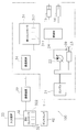
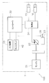
- FIG. 3 is a block diagram showing a configuration of a system 100 for displaying an image of the work machine 1 and its surroundings, and a flow of processing by the system.
- the system 100 includes a plurality of cameras C1-C4.
- the plurality of cameras C1-C4 are attached to the vehicle body 2.
- the plurality of cameras C1-C4 are fisheye cameras.
- the angle of view of each of the plurality of cameras C1-C4 is 180 degrees. However, the angle of view of each of the plurality of cameras C1-C4 may be smaller than 180 degrees. Alternatively, the angle of view of each of the plurality of cameras C1-C4 may be greater than 180 degrees.
- the plurality of cameras C1-C4 includes a front camera C1, a first side camera C2, a rear camera C3, and a second side camera C4.
- the front camera C1 is attached to the front part of the vehicle body 2.
- the vehicle body 2 includes a support member 18.
- the support member 18 extends upward and forward from the front portion of the vehicle body 2.
- the front camera C1 is attached to the support member 18.
- the rear camera C3 is attached to the rear part of the vehicle body 2.
- the first side camera C2 is attached to one side of the vehicle body 2.
- the second side camera C4 is attached to the other side portion of the vehicle body 2.
- the first side camera C2 is attached to the left side portion of the vehicle body 2, and the second side camera C4 is attached to the right side portion of the vehicle body 2.
- the first side camera C2 may be attached to the right side portion of the vehicle body 2, and the second side camera C4 may be attached to the left side portion of the vehicle body 2.
- the front camera C1 acquires an image in front of the vehicle body 2.
- the rear camera C3 acquires an image behind the work machine 1.
- the first side camera C2 acquires an image on the left side of the vehicle body 2.
- the second side camera C4 acquires an image on the right side of the vehicle body 2.
- the cameras C1-C4 output image data indicating the acquired image.
- the system 100 includes a shape sensor 36, a posture sensor 37, and a position sensor 38.
- the shape sensor 36 measures a three-dimensional shape of an object around the work machine 1 and outputs shape data D1 indicating the three-dimensional shape.
- the shape sensor 36 measures the positions of a plurality of points on the object around the work machine 1.
- the shape data D1 indicates the positions of a plurality of points on the object around the work machine 1.
- the target around the work machine 1 includes, for example, the terrain around the work machine 1. That is, the shape data D1 includes the positions of a plurality of points on the terrain around the work machine 1. Particularly, the shape data D1 includes the positions of a plurality of points on the terrain in front of the work machine 1.
- the shape sensor 36 measures the distances from the work machine 1 at the positions of a plurality of points on the surrounding object. The positions of the plurality of points are obtained from the distances from the work machine 1 at the plurality of points.
- the shape sensor 36 is, for example, a rider (LIDAR: Laser Imaging Detection and Ranging). The shape sensor 36 measures the distance to the measurement point by irradiating a laser and measuring the reflected light.
- the attitude sensor 37 detects the attitude of the work machine 1 and outputs attitude data D2 indicating the attitude.
- the posture sensor 37 is, for example, an IMU (inertial measurement unit: Inertial Measurement Unit).
- the posture data D2 includes an angle (pitch angle) with respect to the horizontal in the vehicle front-rear direction and an angle (roll angle) with respect to the horizontal in the vehicle lateral direction.
- the attitude sensor outputs attitude data D2.
- the position sensor 38 is, for example, a GNSS (Global Navigation Satellite System) receiver.
- the position sensor is, for example, a receiver for GPS (Global Positioning System).
- the position sensor receives the positioning signal from the satellite, and acquires the position data D3 indicating the position coordinates of the work machine 1 from the positioning signal.
- the position sensor outputs position data D3.
- the shape sensor 36 is attached to the support member 18, for example. Alternatively, the shape sensor 36 may be attached to another part of the vehicle body 2.
- the attitude sensor 37 and the position sensor 38 are attached to the vehicle body 2. Alternatively, the attitude sensor 37 and the position sensor 38 may be attached to the work machine 3.
- the system 100 includes an image controller 41 and a display 42.
- the image controller 41 is programmed to generate an image IS showing the work machine 1 and its periphery and display the image IS on the display 42.
- the image controller 41 includes a memory 411 and a processor 412.
- the memory 411 includes, for example, a volatile memory such as a RAM and a non-volatile memory such as a ROM.
- the memory 411 stores a program and data for generating the image IS.
- the processor 412 is, for example, a CPU (Central Processing Unit), and executes processing for generating an image IS and displaying it on the display 42 according to a program.
- CPU Central Processing Unit
- the image controller 41 is connected to the first controller 31 by wire or wirelessly so as to be communicable.
- the image controller 41 is connected to the second controller 32 in a wired or wireless manner so that they can communicate with each other.
- the image controller 41 may be mounted on the work machine 1.
- the image controller 41 may be integrated with the first controller 31 or may be a separate body.
- the image controller 41 may be arranged outside the work machine 1.
- the image controller 41 may be arranged in the control center.
- the image controller 41 may be integrated with the second controller 32 or may be a separate body.
- the image controller 41 is connected to the cameras C1-C4 by wire or wirelessly so that they can communicate with each other.
- the image controller 41 receives image data from the cameras C1-C4.
- the image controller 41 may receive the image data via the first controller 31 and/or the second controller 32.
- the image controller 41 is connected to the shape sensor 36, the posture sensor 37, and the position sensor 38 by wire or wirelessly so that they can communicate with each other.
- the image controller 41 receives the shape data D1 from the shape sensor 36.
- the image controller 41 receives the posture data D2 from the posture sensor 37.
- the image controller 41 receives the position data D3 from the position sensor 38.
- the image controller 41 may receive the shape data D1, the posture data D2, and the position data D3 via the first controller 31 and/or the second controller 32.
- the display 42 is, for example, a CRT, LCD or OELD. However, the display 42 is not limited to these displays and may be another type of display.
- the display 42 displays an image based on the signal from the image controller 41.
- the display 42 may receive a signal from the image controller 41 via the first controller 31 and/or the second controller 32.
- the image controller 41 generates an image IS based on the above-mentioned image data, shape data D1, posture data D2, and position data D3.
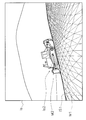
- FIG. 4 is a diagram showing an example of the image IS.
- the image IS includes the work machine 1 and objects around the work machine 1.
- the target around the work machine 1 includes the terrain around the work machine 1. Objects around the work machine 1 may include other work machines, buildings, or people. The generation of the image IS will be described below.
- the cameras C1-C4 take images of the work machine 1 and its surroundings.
- the image controller 41 acquires the front image Im1, the left image Im2, the rear image Im3, and the right image Im4 from the cameras C1-C4.
- the front image Im1 is an image in front of the vehicle body 2.
- the left image Im2 is an image on the left side of the vehicle body 2.
- the rear image Im3 is an image behind the vehicle body 2.
- the right image Im4 is an image on the right side of the vehicle body 2.
- the image controller 41 generates a peripheral image IS1 from the images Im1-Im4 acquired by the cameras C1-C4.
- the peripheral image IS1 is a synthetic image that shows a bird's eye view of the periphery of the work machine 1.
- the image controller 41 generates the peripheral image IS1 by projecting the images Im1-Im4 acquired by the cameras C1-C4 on the three-dimensional projection model M1 by texture mapping.
- the three-dimensional projection model M1 is composed of a polygon mesh indicating the shape of the target around the work machine 1.
- the image controller 41 may use a three-dimensional projection model M1 stored in advance. Alternatively, the image controller 41 may generate the three-dimensional projection model M1 based on the shape data D1 acquired from the shape sensor 36.
- the image controller 41 synthesizes the machine image IS2 showing the work machine 1 and the peripheral image IS1.
- the machine image IS2 is a three-dimensional image of the work machine 1 itself.
- the image controller 41 determines the posture of the machine image IS2 on the image IS from the posture data D2.
- the image controller 41 determines the orientation of the machine image IS2 on the image IS from the position data D3.
- the image controller 41 synthesizes the mechanical image IS2 with the image IS so that the orientation and orientation of the mechanical image IS2 on the image IS match the actual orientation and orientation of the work machine 1.
- the image controller 41 may generate the machine image IS2 from the images Im1-Im4 acquired by the cameras C1-C4.
- the image of the work machine 1 is included in each of the images captured by the cameras C1-C4, and the image controller 41 generates the machine image IS2 by projecting each part of the image onto the machine model M2.
- the machine model M2 may be a projection model having the shape of the work machine 1 and may be stored in the memory 411.
- the machine image IS2 may be a preset image captured in advance or a three-dimensional computer graphics created in advance.
- the display 42 displays the image IS.
- the image IS is updated in real time and displayed on the display 42 as a moving image. Therefore, when the work machine 1 is running, the posture, orientation, and orientation of the peripheral image IS1 and the machine image IS2 in the image IS are determined according to the surrounding objects, the orientation, orientation, and actual position of the work machine 1. The position is also changed and displayed in real time.
- the three-dimensional projection model M1 and the machine model M2 are changed from the posture, orientation, and position when the work machine 1 starts traveling. It rotates according to the rotation matrix that it represents and translates according to the translation vector.
- the rotation vector and the translation vector are acquired from the posture data D2 and the position data D3 described above.
- the image IS is an image of the work machine 1 and its surroundings viewed from the left.
- the image controller 41 can switch the image IS to an image of the work machine 1 and its surroundings from a perspective of forward, backward, rightward, upward, or an oblique direction in each direction.
- the image controller 41 generates an image IS from a viewpoint according to the traveling state of the work machine 1 and displays it on the display 42.
- FIG. 5 is a flowchart showing a process for switching the viewpoint of the image IS according to the running state.
- the image controller 41 acquires running state determination data.
- the determination data includes the shape data D1, the posture data D2, the position data D3, and the operation data D4 described above.
- the determination data also includes vehicle speed data D5.
- the image controller 41 acquires vehicle speed data D5 indicating the vehicle speed from the signal from the vehicle speed sensor 39. Alternatively, the vehicle speed may be calculated from the position data D3.
- step S102 the image controller 41 determines the running state of the work machine 1 based on the determination data.
- the traveling states of the work machine 1 include forward traveling, backward traveling, rightward turning, leftward turning, uphill traveling, downhill traveling, and shoe slip states.
- the image controller 41 determines which of these states the current traveling state of the work machine 1 is based on the determination data.
- the image controller 41 determines whether the traveling state of the work machine 1 is forward or reverse based on the traveling direction of the work machine 1, the position of the work machine 3, and the vehicle speed. Specifically, when the operation data D4 indicates the forward movement of the work machine 1 and the upward movement of the work machine 3, and the vehicle speed is equal to or higher than a predetermined threshold value, the image controller 41 determines that the traveling state is the forward movement. .. When the operation data D4 indicates that the work machine 1 is moving backward, the work machine 3 is moving upward, and the vehicle speed is equal to or higher than a predetermined threshold value, the image controller 41 determines that the traveling state is reverse.
- the image controller 41 determines from the operation data D4 whether the traveling state of the work machine 1 is a right turn or a left turn. Specifically, the image controller 41 determines that the traveling state of the work machine 1 is a right turn when the operation data D4 indicates a right turn of the work machine 1. Alternatively, the image controller 41 may determine from the posture data D2 whether the traveling state of the work machine 1 is a right turn or a left turn. The image controller 41 may determine that the traveling state of the work machine 1 is a right turn when the posture data D2 indicates that the azimuth angle of the work machine 1 has changed to the right. Alternatively, the image controller 41 may determine from the position data D3 whether the traveling state of the work machine 1 is a right turn or a left turn.
- the image controller 41 may determine that the traveling state of the work machine 1 is a right turn.
- the determination of the left turn is the same as the determination of the right turn, except that it is bilaterally symmetric.
- the image controller 41 determines from the operation data D4 and the shape data D1 whether the traveling state of the work machine 1 is uphill traveling or downhill traveling. Specifically, the image controller 41 determines that the operation data D4 indicates the forward movement of the work machine 1 and the shape data D1 indicates that the terrain in front of the work machine 1 is an uphill slope. It is determined that the traveling state of 1 is uphill traveling. The image controller 41 indicates that the operation data D4 indicates that the work machine 1 is moving forward, and the shape data D1 indicates that the terrain in front of the work machine 1 is a downhill. It is determined that the traveling state of 1 is the descending traveling.
- the image controller 41 calculates the ratio of the actual vehicle speed and the theoretical vehicle speed as the shoe slip ratio.
- the actual vehicle speed is the vehicle speed indicated by the vehicle speed data D5.
- the theoretical vehicle speed is the vehicle speed obtained from the position data D3.
- the image controller 41 determines whether the traveling state of the work machine 1 is the shoe slip state by comparing the shoe slip rate with a predetermined threshold value.
- step S103 the image controller 41 determines the viewpoint according to the running state.
- the image controller 41 stores data that defines the position of the viewpoint according to the running state.
- the image controller 41 refers to the data and determines the viewpoint according to the traveling state.
- step S104 the image controller 41 generates the image IS from the viewpoint VP according to the traveling state.
- step S105 the image controller 41 causes the display 42 to display the image IS from the viewpoint VP according to the traveling state.
- FIG. 6 and 7 are diagrams showing the position of the viewpoint VP according to the traveling state.
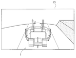
- the image controller 41 determines the viewpoint VP of the image IS at a position behind and above the work machine 1.
- the image controller 41 generates an image IS from the viewpoint VP behind and above the work machine 1, and causes the display 42 to display the image IS.
- the image IS during forward movement shows the entire work machine 1 and the periphery of the work machine 1.
- the image controller 41 determines the position of the viewpoint VP and the position of the work machine 1 so that the front side of the work machine 1 is wider than the rear side in the forward movement image IS.
- the image controller 41 determines the viewpoint VP of the image IS at a position in front of and above the work machine 1 when the traveling state is reverse. As a result, as shown in FIG. 9, the image controller 41 generates the image IS from the viewpoint VP in front of and above the work machine 1, and causes the display 42 to display the image IS.
- the image IS during reverse travel shows the entire work machine 1 and the periphery of the work machine 1.
- the image controller 41 determines the position of the viewpoint VP and the position of the work machine 1 so that the rear side of the work machine 1 is wider than the front side in the image IS when moving backward.
- the image controller 41 determines the viewpoint VP of the image IS at a position to the right and above the position directly behind the work machine 1 when the traveling state is turning right. Thereby, as shown in FIG. 10, the image controller 41 generates the image IS from the viewpoint VP from which the right side of the work machine 1 can be seen, and causes the display 42 to display the image IS.
- the image IS when turning right shows the entire work machine 1 and the periphery of the work machine 1.
- the image controller 41 determines the position of the viewpoint VP and the position of the work machine 1 so that the right side of the work machine 1 is wider than the left side in the image IS when turning right.
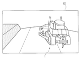
- the image controller 41 determines the viewpoint VP of the image IS at a position to the left and above the position directly behind the work machine 1 when the traveling state is a left turn. Thereby, as shown in FIG. 11, the image controller 41 generates the image IS from the viewpoint VP from which the left side portion of the work machine 1 can be seen, and causes the display 42 to display the image IS.
- the image IS when turning left shows the entire work machine 1 and the periphery of the work machine 1.
- the image controller 41 determines the position of the viewpoint VP and the position of the work machine 1 so that the left side of the work machine 1 is wider than the right side in the image IS when turning left.
- the image controller 41 determines the viewpoint VP of the image IS at a position behind the work machine 1 just beside. As a result, as shown in FIG. 12, the image controller 41 generates an image IS from a viewpoint VP that is behind the work machine 1 and is displayed on the display 42.
- the image IS when traveling uphill shows the entire work machine 1 and the periphery of the work machine 1.
- the image controller 41 determines the position of the viewpoint VP and the position of the work machine 1 so that the front side of the work machine 1 is wider than the rear side in the image IS when traveling uphill.
- the image controller 41 determines the position of the viewpoint VP and the position of the work machine 1 so that the work machine 1 has a size about half the width of the image IS in the image IS when traveling uphill.
- the image controller 41 determines the viewpoint VP of the image IS at a position in front of the side of the work machine 1 when the traveling state is the descending traveling. Thereby, as shown in FIG. 13, the image controller 41 generates the image IS from the viewpoint VP in front of the side of the work machine 1, and causes the display 42 to display the image IS.
- the image IS during traveling of the descending plate shows the entire work machine 1 and the periphery of the work machine 1.
- the image controller 41 determines the position of the viewpoint VP and the position of the work machine 1 so that the front side of the work machine 1 is wider than the rear side in the image IS when the plate is traveling.
- the image controller 41 determines the position of the viewpoint VP and the position of the work machine 1 so that the work machine 1 has a size of about half the width of the image IS in the image IS when the plate is traveling.
- the image controller 41 determines the viewpoint VP of the image IS at a lateral position of the crawler belt 13 when the traveling state is the shoeslip state. Specifically, when the left crawler belt 13 is in the shoeslip state, the viewpoint VP of the image IS is determined to be the left position of the left crawler belt 13. Thereby, as shown in FIG. 14, the image controller 41 generates an image IS from the left viewpoint VP of the left crawler belt 13 and causes the display 42 to display the image IS.
- the viewpoint VP of the image IS is set to the right position of the right crawler belt 13.
- the image controller 41 generates the image IS from the right viewpoint VP of the right crawler belt 13 and causes the display 42 to display the image IS.
- the image controller 41 determines the position of the viewpoint VP and the position of the work machine 1 so that the front side of the work machine 1 is wider than the rear side.
- the image controller 41 determines the position of the viewpoint VP and the position of the work machine 1 so that the work machine 1 has a size of about half the width of the image IS in the image IS in the shoe slip state.
- the image controller 41 repeatedly executes steps S101 to S105 described above. Therefore, when the traveling state of the work machine 1 changes, the viewpoint VP is changed in step S103 according to the change in the traveling state. Then, in step S104, the image IS from the viewpoint VP changed according to the change in the running state is generated, and in step S105, the changed image IS is displayed on the display 42.
- the traveling state of the work machine 1 is acquired. Then, the image IS from the viewpoint VP according to the traveling state is generated and displayed on the display 42. Therefore, the user can easily use the image IS at the viewpoint VP according to the traveling state of the work machine 1.
- the image controller 41 generates images IS from different viewpoints VP when the traveling state is forward, backward, right turn, or left turn. Specifically, when the traveling state is forward, an image IS from the viewpoint VP behind the work machine 1 is displayed on the display 42. Therefore, it is easy to visually recognize the front of the work machine 1. When the traveling state is reverse, the image IS from the viewpoint VP in front of the work machine 1 is displayed on the display 42. Therefore, it is easy to visually recognize the rear of the work machine 1.
- the traveling state is a left turn
- the image IS from the viewpoint VP on the left side of the rear side is displayed on the display 42 so that the left side portion of the work machine 1 can be seen. Therefore, it can be easily understood from the image IS that the work machine 1 is turning left.
- the image controller 41 generates images IS from different viewpoints VP when the traveling state is uphill traveling or downhill traveling. Specifically, when the traveling state is uphill traveling, the image IS from the viewpoint VP behind the work machine 1 is displayed on the display 42. Therefore, the upslope of the terrain can be easily grasped by the image IS. When the traveling state is the descending traveling, the image IS from the viewpoint VP in front of the work machine 1 is displayed on the display 42. Therefore, the down slope of the terrain can be easily grasped by the image IS.
- the work machine is not limited to a bulldozer, but may be another type such as a wheel loader or a hydraulic excavator.
- the work machine 1 may be operated in the cab instead of being operated remotely.
- FIG. 15: is a figure which shows the structure of the working machine 1 which concerns on a modification.
- the work machine 1 may include a controller 30 mounted on the work machine 1.
- the controller 30 has the same configuration as the first controller 31 and the second controller 32 described above, and thus detailed description thereof will be omitted.
- the controller 30 may execute the processes of steps S101 to S105 described above.
- the input device 33 may be arranged in the cab.
- the first controller 31 is not limited to a single unit and may be divided into a plurality of controllers.
- the second controller 32 is not limited to be integrated, and may be divided into a plurality of controllers.
- the controller 30 is not limited to a single unit and may be divided into a plurality of controllers.
- steps S101 to S105 described above may be executed by another controller instead of the image controller 41.
- the processes of steps S101 to S103 may be executed by the first controller 31 or the second controller 32.
- the number of cameras is not limited to four, but may be three or less, or five or more.
- the camera is not limited to a fisheye camera, and may be another type of camera.
- the arrangement of the cameras is not limited to the arrangement of the above-described embodiment, but may be different arrangement.
- the attitude sensor 37 is not limited to the IMU and may be another sensor.
- the position sensor 38 is not limited to the GNSS receiver and may be another sensor.
- the shape sensor 36 is not limited to the rider, but may be another measuring device such as a radar.
- the type of running state is not limited to that of the above embodiment, and may be changed. For example, some of the types of running states may be omitted. Alternatively, other types of driving states may be added.
- the method of determining the traveling state is not limited to that of the above embodiment, and may be changed. For example, the traveling state may be determined based on a signal from a sensor that detects the operation of the work machine 3.
- the position of the viewpoint VP in each traveling state is not limited to that in the above embodiment, and may be changed.
- the user can easily use the image from the viewpoint according to the running state of the work machine.
Landscapes
- Engineering & Computer Science (AREA)
- Mining & Mineral Resources (AREA)
- Civil Engineering (AREA)
- General Engineering & Computer Science (AREA)
- Structural Engineering (AREA)
- Multimedia (AREA)
- Mechanical Engineering (AREA)
- Physics & Mathematics (AREA)
- Signal Processing (AREA)
- General Physics & Mathematics (AREA)
- Theoretical Computer Science (AREA)
- Component Parts Of Construction Machinery (AREA)
- Image Analysis (AREA)
- Fittings On The Vehicle Exterior For Carrying Loads, And Devices For Holding Or Mounting Articles (AREA)
- Image Processing (AREA)
- Closed-Circuit Television Systems (AREA)
Abstract
Description
3 作業機
13 履帯
42 ディスプレイ
412 プロセッサ
C1-C4 カメラ
Claims (20)
- 作業機を含む作業機械と、
前記作業機械の周辺を示す画像を撮影する複数のカメラと、
前記複数のカメラが撮影した前記画像を示す画像データを取得し、前記作業機械の走行状態を取得し、前記画像を合成して、前記走行状態に応じた視点からの画像を生成するプロセッサと、
前記プロセッサからの信号に基づき、前記走行状態に応じた視点からの前記画像を表示するディスプレイと、
を備えるシステム。
- 前記走行状態は、前進と旋回とを含み、
前記プロセッサは、前記走行状態が前進であるときと旋回であるときとでは、異なる視点からの画像を生成する、
請求項1に記載のシステム。
- 前記走行状態は、後進と旋回とを含み、
前記プロセッサは、前記走行状態が後進であるときと旋回であるときとでは、異なる視点からの画像を生成する、
請求項1に記載のシステム。
- 前記走行状態は、前進と後進とを含み、
前記プロセッサは、前記走行状態が前進であるときと後進であるときとでは、異なる視点からの画像を生成する、
請求項1に記載のシステム。
- 前記プロセッサは、前記走行状態が旋回であるときには、前記作業機械の側部が見える視点からの画像を生成する、
請求項2に記載のシステム。
- 前記プロセッサは、前記走行状態が前進であるときには、前記作業機械の後方の視点からの画像を生成する、
請求項2に記載のシステム。
- 前記プロセッサは、前記走行状態が後進であるときには、前記作業機械の前方の視点からの画像を生成する、
請求項3に記載のシステム。
- 前記プロセッサは、前記作業機械の全体と前記作業機械の周辺とを示す画像を生成する、
請求項1に記載のシステム。
- 前記走行状態は、登坂走行を含み、
前記プロセッサは、前記走行状態が前記登坂走行であるときには、前記作業機械の真横よりも後方の視点からの画像を生成する、
請求項1に記載のシステム。
- 前記走行状態は、降板走行を含み、
前記プロセッサは、前記走行状態が前記降板走行であるときには、前記作業機械の真横よりも前方の視点からの画像を生成する、
請求項1に記載のシステム。
- 前記作業機械は、履帯を含み、
前記走行状態は、前記履帯のシュースリップ状態を含み、
前記プロセッサは、前記走行状態が前記シュースリップ状態であるときには、前記履帯の側方の視点からの画像を生成する、
請求項1に記載のシステム。
- 作業機を含む作業機械の周辺をディスプレイに表示するためにプロセッサによって実行される方法であって、
複数のカメラによって前記作業機械の周辺を示す画像を撮影することと、
前記複数のカメラが撮影した前記画像を示す画像データを取得することと、
前記作業機械の走行状態を取得することと、
前記画像を合成して、前記走行状態に応じた視点からの画像を生成することと、
前記走行状態に応じた視点からの前記画像を前記ディスプレイに表示すること、
を備える方法。
- 前記走行状態は、前進と旋回とを含み、
画像を生成することは、前記走行状態が前進であるときと旋回であるときとでは、異なる視点からの画像を生成することを含む、
請求項12に記載の方法。
- 前記走行状態は、後進と旋回とを含み、
前記画像を生成することは、前記走行状態が後進であるときと旋回であるときとでは、異なる視点からの画像を生成することを含む、
請求項12に記載の方法。
- 前記走行状態は、前進と後進とを含み、
前記画像を生成することは、前記走行状態が前進であるときと後進であるときとでは、異なる視点からの画像を生成することを含む、
請求項12に記載の方法。
- 前記画像を生成することは、前記走行状態が旋回であるときには、前記作業機械の側部が見える視点からの画像を生成することを含む、
請求項13に記載の方法。
- 前記画像を生成することは、前記走行状態が前進であるときには、前記作業機械の後方の視点からの画像を生成することを含む、
請求項13に記載の方法。
- 前記走行状態が後進であるときには、前記作業機械の前方の視点からの画像を生成することを含む、
請求項14に記載の方法。
- 前記走行状態は、登坂走行を含み、
前記画像を生成することは、前記走行状態が前記登坂走行であるときには、前記作業機械の真横よりも後方の視点からの画像を生成することを含む、
請求項12に記載の方法。
- 作業機械の周辺を示す画像を示す画像データを取得し、前記作業機械の走行状態を取得し、前記画像を合成して、前記走行状態に応じた視点からの画像を生成するプロセッサと、
前記プロセッサからの信号に基づき、前記走行状態に応じた視点からの前記画像を表示するディスプレイと、
を備えるシステム。
Priority Applications (3)
| Application Number | Priority Date | Filing Date | Title |
|---|---|---|---|
| AU2020211868A AU2020211868B2 (en) | 2019-01-23 | 2020-01-20 | System and method for work machine |
| CA3118562A CA3118562C (en) | 2019-01-23 | 2020-01-20 | A system and method for generating images based on work machine traveling state |
| US17/289,383 US20220002977A1 (en) | 2019-01-23 | 2020-01-20 | System and method for work machine |
Applications Claiming Priority (2)
| Application Number | Priority Date | Filing Date | Title |
|---|---|---|---|
| JP2019-008903 | 2019-01-23 | ||
| JP2019008903A JP7160701B2 (ja) | 2019-01-23 | 2019-01-23 | 作業機械のシステム及び方法 |
Publications (1)
| Publication Number | Publication Date |
|---|---|
| WO2020153315A1 true WO2020153315A1 (ja) | 2020-07-30 |
Family
ID=71735602
Family Applications (1)
| Application Number | Title | Priority Date | Filing Date |
|---|---|---|---|
| PCT/JP2020/001775 Ceased WO2020153315A1 (ja) | 2019-01-23 | 2020-01-20 | 作業機械のシステム及び方法 |
Country Status (5)
| Country | Link |
|---|---|
| US (1) | US20220002977A1 (ja) |
| JP (1) | JP7160701B2 (ja) |
| AU (1) | AU2020211868B2 (ja) |
| CA (1) | CA3118562C (ja) |
| WO (1) | WO2020153315A1 (ja) |
Citations (4)
| Publication number | Priority date | Publication date | Assignee | Title |
|---|---|---|---|---|
| JP2010059653A (ja) * | 2008-09-02 | 2010-03-18 | Hitachi Constr Mach Co Ltd | 作業機械の視野補助装置 |
| JP2013168826A (ja) * | 2012-02-16 | 2013-08-29 | Hitachi Constr Mach Co Ltd | 作業機械の周囲監視装置 |
| JP2016149803A (ja) * | 2016-04-22 | 2016-08-18 | 日立建機株式会社 | 作業機械の周囲監視装置 |
| WO2016158265A1 (ja) * | 2015-03-31 | 2016-10-06 | 株式会社小松製作所 | 作業機械 |
Family Cites Families (17)
| Publication number | Priority date | Publication date | Assignee | Title |
|---|---|---|---|---|
| WO2012157379A1 (ja) * | 2011-05-13 | 2012-11-22 | 日立建機株式会社 | 作業機械の周囲監視装置 |
| US9651381B2 (en) * | 2014-01-10 | 2017-05-16 | Caterpillar Inc. | Terrain mapping system using virtual tracking features |
| US10293752B2 (en) * | 2014-08-28 | 2019-05-21 | The University Of Tokyo | Display system for work vehicle, display control device, work vehicle, and display control method |
| KR101641490B1 (ko) * | 2014-12-10 | 2016-07-21 | 엘지전자 주식회사 | 차량 운전 보조 장치 및 이를 구비한 차량 |
| US10523865B2 (en) * | 2016-01-06 | 2019-12-31 | Texas Instruments Incorporated | Three dimensional rendering for surround view using predetermined viewpoint lookup tables |
| JP6597415B2 (ja) * | 2016-03-07 | 2019-10-30 | 株式会社デンソー | 情報処理装置及びプログラム |
| JP6723820B2 (ja) * | 2016-05-18 | 2020-07-15 | 株式会社デンソーテン | 画像生成装置、画像表示システムおよび画像表示方法 |
| JP2018001901A (ja) * | 2016-06-30 | 2018-01-11 | アイシン精機株式会社 | 走行支援装置 |
| JP6759899B2 (ja) * | 2016-09-08 | 2020-09-23 | アイシン精機株式会社 | 車両用画像処理装置 |
| JP6766557B2 (ja) * | 2016-09-29 | 2020-10-14 | アイシン精機株式会社 | 周辺監視装置 |
| WO2018061294A1 (ja) * | 2016-09-30 | 2018-04-05 | アイシン精機株式会社 | 周辺監視装置 |
| EP3537714B1 (en) * | 2017-02-28 | 2021-08-25 | JVC Kenwood Corporation | Bird's-eye-view video image generation device, bird's-eye-view video image generation system, bird's-eye-view video image generation method, and program |
| JP6852465B2 (ja) * | 2017-03-02 | 2021-03-31 | 株式会社Jvcケンウッド | 俯瞰映像生成装置、俯瞰映像生成システム、俯瞰映像生成方法およびプログラム |
| CN111386215B (zh) * | 2017-12-15 | 2024-01-19 | 株式会社久保田 | 滑移判定系统、行驶路径生成系统以及田地作业车 |
| JP7151293B2 (ja) * | 2018-09-06 | 2022-10-12 | 株式会社アイシン | 車両周辺表示装置 |
| CN112867631B (zh) * | 2018-11-13 | 2024-04-12 | 瑞维安知识产权控股有限责任公司 | 用于控制车辆摄像头的系统和方法 |
| JP7283059B2 (ja) * | 2018-11-28 | 2023-05-30 | 株式会社アイシン | 周辺監視装置 |
-
2019
- 2019-01-23 JP JP2019008903A patent/JP7160701B2/ja active Active
-
2020
- 2020-01-20 CA CA3118562A patent/CA3118562C/en active Active
- 2020-01-20 AU AU2020211868A patent/AU2020211868B2/en active Active
- 2020-01-20 US US17/289,383 patent/US20220002977A1/en not_active Abandoned
- 2020-01-20 WO PCT/JP2020/001775 patent/WO2020153315A1/ja not_active Ceased
Patent Citations (4)
| Publication number | Priority date | Publication date | Assignee | Title |
|---|---|---|---|---|
| JP2010059653A (ja) * | 2008-09-02 | 2010-03-18 | Hitachi Constr Mach Co Ltd | 作業機械の視野補助装置 |
| JP2013168826A (ja) * | 2012-02-16 | 2013-08-29 | Hitachi Constr Mach Co Ltd | 作業機械の周囲監視装置 |
| WO2016158265A1 (ja) * | 2015-03-31 | 2016-10-06 | 株式会社小松製作所 | 作業機械 |
| JP2016149803A (ja) * | 2016-04-22 | 2016-08-18 | 日立建機株式会社 | 作業機械の周囲監視装置 |
Also Published As
| Publication number | Publication date |
|---|---|
| JP7160701B2 (ja) | 2022-10-25 |
| CA3118562A1 (en) | 2020-07-30 |
| US20220002977A1 (en) | 2022-01-06 |
| AU2020211868B2 (en) | 2023-03-09 |
| JP2020117914A (ja) | 2020-08-06 |
| CA3118562C (en) | 2023-08-29 |
| AU2020211868A1 (en) | 2021-05-27 |
Similar Documents
| Publication | Publication Date | Title |
|---|---|---|
| US20200399869A1 (en) | Image display system for work machine, remote operation system for work machine, and work machine | |
| EP4159933B1 (en) | Construction assisting system for shovel | |
| AU2017318911B2 (en) | Image display system of work machine, remote operation system of work machine, work machine, and method for displaying image of work machine | |
| JP7721305B2 (ja) | 建設機械の管理システム | |
| US20220316188A1 (en) | Display system, remote operation system, and display method | |
| US12084840B2 (en) | System and method for work machine | |
| US11549238B2 (en) | System and method for work machine | |
| US20220049457A1 (en) | Control system and control method for work machine | |
| JP2020197045A (ja) | 表示システムおよび表示方法 | |
| JP7122980B2 (ja) | 作業機械のシステム及び方法 | |
| US12091839B2 (en) | System and method for work machine | |
| JP7160701B2 (ja) | 作業機械のシステム及び方法 | |
| US20250003197A1 (en) | Supporting device, work machine, and program |
Legal Events
| Date | Code | Title | Description |
|---|---|---|---|
| 121 | Ep: the epo has been informed by wipo that ep was designated in this application |
Ref document number: 20744511 Country of ref document: EP Kind code of ref document: A1 |
|
| ENP | Entry into the national phase |
Ref document number: 3118562 Country of ref document: CA |
|
| ENP | Entry into the national phase |
Ref document number: 2020211868 Country of ref document: AU Date of ref document: 20200120 Kind code of ref document: A |
|
| NENP | Non-entry into the national phase |
Ref country code: DE |
|
| 122 | Ep: pct application non-entry in european phase |
Ref document number: 20744511 Country of ref document: EP Kind code of ref document: A1 |