WO2020152903A1 - レーザ照射装置及びレーザ照射プログラムを格納する記憶媒体 - Google Patents
レーザ照射装置及びレーザ照射プログラムを格納する記憶媒体 Download PDFInfo
- Publication number
- WO2020152903A1 WO2020152903A1 PCT/JP2019/034541 JP2019034541W WO2020152903A1 WO 2020152903 A1 WO2020152903 A1 WO 2020152903A1 JP 2019034541 W JP2019034541 W JP 2019034541W WO 2020152903 A1 WO2020152903 A1 WO 2020152903A1
- Authority
- WO
- WIPO (PCT)
- Prior art keywords
- laser
- target
- detection
- laser light
- coping
- Prior art date
- Legal status (The legal status is an assumption and is not a legal conclusion. Google has not performed a legal analysis and makes no representation as to the accuracy of the status listed.)
- Ceased
Links
Images


Classifications
-
- F—MECHANICAL ENGINEERING; LIGHTING; HEATING; WEAPONS; BLASTING
- F41—WEAPONS
- F41H—ARMOUR; ARMOURED TURRETS; ARMOURED OR ARMED VEHICLES; MEANS OF ATTACK OR DEFENCE, e.g. CAMOUFLAGE, IN GENERAL
- F41H13/00—Means of attack or defence not otherwise provided for
- F41H13/0043—Directed energy weapons, i.e. devices that direct a beam of high energy content toward a target for incapacitating or destroying the target
- F41H13/005—Directed energy weapons, i.e. devices that direct a beam of high energy content toward a target for incapacitating or destroying the target the high-energy beam being a laser beam
- F41H13/0062—Directed energy weapons, i.e. devices that direct a beam of high energy content toward a target for incapacitating or destroying the target the high-energy beam being a laser beam causing structural damage to the target
-
- G—PHYSICS
- G01—MEASURING; TESTING
- G01S—RADIO DIRECTION-FINDING; RADIO NAVIGATION; DETERMINING DISTANCE OR VELOCITY BY USE OF RADIO WAVES; LOCATING OR PRESENCE-DETECTING BY USE OF THE REFLECTION OR RERADIATION OF RADIO WAVES; ANALOGOUS ARRANGEMENTS USING OTHER WAVES
- G01S17/00—Systems using the reflection or reradiation of electromagnetic waves other than radio waves, e.g. lidar systems
- G01S17/02—Systems using the reflection of electromagnetic waves other than radio waves
- G01S17/06—Systems determining position data of a target
- G01S17/42—Simultaneous measurement of distance and other co-ordinates
-
- G—PHYSICS
- G01—MEASURING; TESTING
- G01S—RADIO DIRECTION-FINDING; RADIO NAVIGATION; DETERMINING DISTANCE OR VELOCITY BY USE OF RADIO WAVES; LOCATING OR PRESENCE-DETECTING BY USE OF THE REFLECTION OR RERADIATION OF RADIO WAVES; ANALOGOUS ARRANGEMENTS USING OTHER WAVES
- G01S17/00—Systems using the reflection or reradiation of electromagnetic waves other than radio waves, e.g. lidar systems
- G01S17/66—Tracking systems using electromagnetic waves other than radio waves
-
- G—PHYSICS
- G01—MEASURING; TESTING
- G01S—RADIO DIRECTION-FINDING; RADIO NAVIGATION; DETERMINING DISTANCE OR VELOCITY BY USE OF RADIO WAVES; LOCATING OR PRESENCE-DETECTING BY USE OF THE REFLECTION OR RERADIATION OF RADIO WAVES; ANALOGOUS ARRANGEMENTS USING OTHER WAVES
- G01S17/00—Systems using the reflection or reradiation of electromagnetic waves other than radio waves, e.g. lidar systems
- G01S17/88—Lidar systems specially adapted for specific applications
- G01S17/89—Lidar systems specially adapted for specific applications for mapping or imaging
-
- G—PHYSICS
- G01—MEASURING; TESTING
- G01S—RADIO DIRECTION-FINDING; RADIO NAVIGATION; DETERMINING DISTANCE OR VELOCITY BY USE OF RADIO WAVES; LOCATING OR PRESENCE-DETECTING BY USE OF THE REFLECTION OR RERADIATION OF RADIO WAVES; ANALOGOUS ARRANGEMENTS USING OTHER WAVES
- G01S7/00—Details of systems according to groups G01S13/00, G01S15/00, G01S17/00
- G01S7/48—Details of systems according to groups G01S13/00, G01S15/00, G01S17/00 of systems according to group G01S17/00
- G01S7/481—Constructional features, e.g. arrangements of optical elements
- G01S7/4814—Constructional features, e.g. arrangements of optical elements of transmitters alone
- G01S7/4815—Constructional features, e.g. arrangements of optical elements of transmitters alone using multiple transmitters
-
- H—ELECTRICITY
- H01—ELECTRIC ELEMENTS
- H01S—DEVICES USING THE PROCESS OF LIGHT AMPLIFICATION BY STIMULATED EMISSION OF RADIATION [LASER] TO AMPLIFY OR GENERATE LIGHT; DEVICES USING STIMULATED EMISSION OF ELECTROMAGNETIC RADIATION IN WAVE RANGES OTHER THAN OPTICAL
- H01S5/00—Semiconductor lasers
- H01S5/10—Construction or shape of the optical resonator, e.g. extended or external cavity, coupled cavities, bent-guide, varying width, thickness or composition of the active region
- H01S5/18—Surface-emitting [SE] lasers, e.g. having both horizontal and vertical cavities
- H01S5/183—Surface-emitting [SE] lasers, e.g. having both horizontal and vertical cavities having only vertical cavities, e.g. vertical cavity surface-emitting lasers [VCSEL]
- H01S5/18386—Details of the emission surface for influencing the near- or far-field, e.g. a grating on the surface
-
- H—ELECTRICITY
- H01—ELECTRIC ELEMENTS
- H01S—DEVICES USING THE PROCESS OF LIGHT AMPLIFICATION BY STIMULATED EMISSION OF RADIATION [LASER] TO AMPLIFY OR GENERATE LIGHT; DEVICES USING STIMULATED EMISSION OF ELECTROMAGNETIC RADIATION IN WAVE RANGES OTHER THAN OPTICAL
- H01S5/00—Semiconductor lasers
- H01S5/40—Arrangement of two or more semiconductor lasers, not provided for in groups H01S5/02 - H01S5/30
- H01S5/4025—Array arrangements, e.g. constituted by discrete laser diodes or laser bar
- H01S5/4031—Edge-emitting structures
- H01S5/4056—Edge-emitting structures emitting light in more than one direction
-
- H—ELECTRICITY
- H01—ELECTRIC ELEMENTS
- H01S—DEVICES USING THE PROCESS OF LIGHT AMPLIFICATION BY STIMULATED EMISSION OF RADIATION [LASER] TO AMPLIFY OR GENERATE LIGHT; DEVICES USING STIMULATED EMISSION OF ELECTROMAGNETIC RADIATION IN WAVE RANGES OTHER THAN OPTICAL
- H01S5/00—Semiconductor lasers
- H01S5/50—Amplifier structures not provided for in groups H01S5/02 - H01S5/30
-
- H—ELECTRICITY
- H01—ELECTRIC ELEMENTS
- H01S—DEVICES USING THE PROCESS OF LIGHT AMPLIFICATION BY STIMULATED EMISSION OF RADIATION [LASER] TO AMPLIFY OR GENERATE LIGHT; DEVICES USING STIMULATED EMISSION OF ELECTROMAGNETIC RADIATION IN WAVE RANGES OTHER THAN OPTICAL
- H01S5/00—Semiconductor lasers
- H01S5/02—Structural details or components not essential to laser action
- H01S5/022—Mountings; Housings
- H01S5/023—Mount members, e.g. sub-mount members
- H01S5/02325—Mechanically integrated components on mount members or optical micro-benches
- H01S5/02326—Arrangements for relative positioning of laser diodes and optical components, e.g. grooves in the mount to fix optical fibres or lenses
-
- H—ELECTRICITY
- H01—ELECTRIC ELEMENTS
- H01S—DEVICES USING THE PROCESS OF LIGHT AMPLIFICATION BY STIMULATED EMISSION OF RADIATION [LASER] TO AMPLIFY OR GENERATE LIGHT; DEVICES USING STIMULATED EMISSION OF ELECTROMAGNETIC RADIATION IN WAVE RANGES OTHER THAN OPTICAL
- H01S5/00—Semiconductor lasers
- H01S5/10—Construction or shape of the optical resonator, e.g. extended or external cavity, coupled cavities, bent-guide, varying width, thickness or composition of the active region
- H01S5/18—Surface-emitting [SE] lasers, e.g. having both horizontal and vertical cavities
- H01S5/183—Surface-emitting [SE] lasers, e.g. having both horizontal and vertical cavities having only vertical cavities, e.g. vertical cavity surface-emitting lasers [VCSEL]
- H01S5/18344—Surface-emitting [SE] lasers, e.g. having both horizontal and vertical cavities having only vertical cavities, e.g. vertical cavity surface-emitting lasers [VCSEL] characterized by the mesa, e.g. dimensions or shape of the mesa
Definitions
- the present invention relates to a laser irradiation device and a storage medium that stores a laser irradiation program.
- Patent Literature 1 discloses a technique of irradiating a high-power continuous wave laser beam to destroy a target.
- the device described in Patent Document 1 converts high-power continuous wave laser light into pulsed laser light by a pulse converter, and irradiates the converted laser light on a target.
- the optical sensor receives the reflected light of the laser light and detects the target.
- the controller stops the pulse conversion process by the pulse converter, the continuous wave laser light is irradiated to the target and destroys the target.
- Patent Document 2 discloses a technique of changing the irradiation direction of laser according to the wavelength.
- the device described in Patent Document 1 includes a waveguide including two distributed Bragg reflectors, a light entrance for allowing light to enter the waveguide, and a light for exiting light guided in the waveguide. And an emission port.
- Patent Document 3 discloses a technique for changing the irradiation direction of a high-power laser to a non-mechanical type.
- the device described in Patent Document 3 includes a first vertical cavity surface emitting laser (VCSEL: Vertical Cavity Surface Emitting LASER) long in a first direction and a drive circuit for injecting a current into the first vertical cavity surface emitting laser.
- VCSEL Vertical Cavity Surface Emitting LASER
- Prepare Incident light incident on an entrance provided at one end of the first vertical cavity surface emitting laser in the first direction proceeds in the first direction while being reflected in the first vertical cavity surface emitting laser in the vertical direction.
- it is emitted as emitted light from the emission opening on the upper surface of the first vertical cavity surface emitting laser. It is described that the direction in which the emitted light is irradiated is inclined from the normal direction of the emission port to the first direction based on the wavelength of the incident light or the like.
- the present invention has been made in view of the above circumstances, and an object thereof is to provide a laser irradiation device that efficiently performs processing such as target detection using a laser beam.
- Other objects can be understood from the following description and description of the embodiments.
- a laser irradiation device includes a laser array, a detection device, and a control device.
- the laser array includes a plurality of laser oscillators including a first laser oscillator that emits the first detection laser light and a second laser oscillator that emits the second countermeasure laser light.
- the detection device acquires detection information based on the reflected light of the first detection laser light reflected by the target.
- the control device estimates the position of the target based on the detection information, and generates a second handling signal that instructs to irradiate the estimated target position with the second handling laser light.
- the second laser oscillator irradiates the estimated target position with the second countermeasure laser light based on the second countermeasure signal.
- the laser irradiation device includes a laser array in which a plurality of laser oscillators are arranged.
- the plurality of laser oscillators includes a first laser oscillator group including a part of the plurality of laser oscillators and a second laser oscillator group including a part of the plurality of laser oscillators.
- the first laser oscillator group irradiates the first laser light group in the first direction to display the first image in the first direction.
- the second laser oscillator group irradiates the second laser light group in a second direction different from the first direction to display the second image in the second direction.
- a storage medium storing a laser irradiation program controls a first laser oscillator and a second laser oscillator arranged in a laser array, and instructs the first laser oscillator to emit a detection laser beam. Based on the step of generating the detection signal and the detection information obtained by receiving the reflected light reflected by the detection laser light to the target, the countermeasure for instructing the second laser oscillator to irradiate the target with the countermeasure laser light And a non-transitory recording medium storing a program including a step of generating a signal.
- processing such as target detection can be efficiently performed.
- FIG. 1 is a schematic diagram of a laser irradiation apparatus according to an embodiment.
- FIG. 2 is a flowchart regarding the operation of the laser irradiation apparatus according to the embodiment.
- FIG. 3 is a diagram for explaining the detection space of the laser irradiation apparatus according to the embodiment.
- FIG. 4 is a diagram for explaining the process of estimating the target position according to the embodiment.
- FIG. 5 is a diagram for explaining an operation of coping with a plurality of goals in one embodiment.
- FIG. 6 is a diagram for explaining an operation for coping with a moving target in one embodiment.
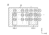
- FIG. 7 is an enlarged view of the laser array for explaining the operation for coping with the moving target according to the embodiment.
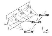
- FIG. 1 is a schematic diagram of a laser irradiation apparatus according to an embodiment.
- FIG. 2 is a flowchart regarding the operation of the laser irradiation apparatus according to the embodiment.
- FIG. 3 is a diagram for explaining the detection space of the
- FIG. 8 is a diagram for explaining an operation of coping with a moving target in one embodiment.
- FIG. 9 is a diagram for explaining the operation of displaying an image on the laser array according to the embodiment.
- FIG. 10 is a diagram for explaining the operation of the laser array that displays different images depending on the viewing direction in the embodiment.
- FIG. 11 is a schematic diagram of a control device in one embodiment.
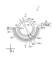
- FIG. 12 is a schematic diagram of a laser oscillator according to an embodiment.
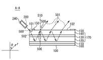
- FIG. 13 is a sectional view taken along line AA of FIG.
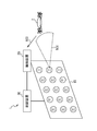
- the laser irradiation apparatus 1 is configured to detect the target 2 and destroy the target 2 by using the output laser light 501.
- the laser irradiation device 1 includes a laser array 10, a detection device 20, and a control device 30.
- the laser array 10 is formed by arranging a plurality of laser oscillators 11 that irradiate the surface with the output laser light 501.
- the laser oscillators 11 may be regularly arranged, for example, in a grid pattern.
- the laser oscillators 11 may be arranged irregularly.
- Laser oscillators 11 are arranged in high density in the laser array 10, and for example, 400 or more laser oscillators 11 are arranged per square meter.
- the laser oscillators 11 may be arranged at 10,000 or more per square meter.
- the laser oscillator 11 can arbitrarily change the irradiation direction of the output laser light 501.
- the laser oscillator 11 changes the irradiation direction of the output laser beam 501 in a non-mechanical manner and two-dimensionally.
- a target 2 for example, a drone exists on the optical path of the output laser light 501 emitted by the laser oscillator 11, the target 2 reflects the output laser light 501 as reflected light 503. Details of the laser oscillator 11 will be described later.
- the detection device 20 receives the reflected light 503 reflected by the target 2 and acquires detection information such as an image of the target 2 captured.
- the detection device 20 includes an optical sensor such as a visible light camera, an infrared camera, or an ultraviolet camera, and images the target 2 illuminated by the output laser light 501.
- the detection device 20 acquires an image of the target 2 captured as detection information and transmits it to the control device 30.
- the detection device 20 may select any device that detects the reflected light 503.
- the control device 30 estimates the position of the target 2 based on the detection information such as the image acquired by the detection device 20.
- the control device 30 extracts the position where the target 2 is shown in the image captured by the detection device 20.
- the control device 30 estimates the position of the target 2 based on the direction captured by the detection device 20 and the position where the target 2 is captured in the captured image.
- the control device 30 transmits a request for irradiating the estimated target position 2 with the output laser beam 501 to the plurality of laser oscillators 11.
- the plurality of laser oscillators 11 irradiate the output laser light 501 at the estimated target 2 position.
- all the laser oscillators 11 capable of irradiating the target 2 position may irradiate the output laser beam 501 to the target 2 position.
- the energy of the output laser light 501 is increased by overlapping the output laser light 501 emitted from the plurality of laser oscillators 11 at the target 2 position.
- the laser irradiation apparatus 1 can destroy the target 2. Therefore, the output laser light 501 emitted from the laser oscillator 11 may have a phase that interferes so that the energy of the output laser light 501 strengthens at the target 2 position. In this case, the phase of the output laser light 501 emitted by each laser oscillator 11 is instructed by the control device 30.
- the laser irradiation apparatus 1 irradiates the output laser light 501 as the detection laser light for detecting the target 2 and outputs the plurality of output laser lights 501 as the countermeasure laser light for attacking the detected target 2.
- Target 2 can be illuminated. Therefore, the detection of the target 2 and the attack on the target 2 can be efficiently performed.
- the laser array 10 may include a laser oscillator 11 that can emit only the detection laser light. Further, the laser array 10 may include a laser oscillator 11 that can emit only the coping laser light. All the laser oscillators 11 included in the laser array 10 may be configured to be able to emit the detection laser light and the coping laser light.
- the operation of the laser irradiation device 1 will be described in more detail.
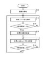
- the laser irradiation device 1 performs the process shown in FIG.
- the detection device 20 starts monitoring for detecting the target 2 such as capturing an image, and acquires detection information.
- the direction detected by the detection device 20, for example, the direction in which an image is captured may be determined based on an instruction from the control device 30.
- the direction detected by the detection device 20 may be fixed in a desired direction.
- the laser oscillator 11 emits the output laser light 501 as the detection laser light.
- the control device 30 determines the laser oscillator 11 that emits the detection laser light and generates a detection signal indicating that the determined laser oscillator 11 is to be irradiated with the detection laser light.
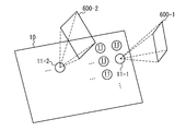
- the laser oscillator 11 for irradiating the detection laser light one that can irradiate the detection space 600 to be detected by the detection laser light among the laser oscillators 11 may be selectively determined.
- the control device 30 transmits a detection signal to the first laser oscillator 11-1 and the second laser oscillator 11-2 among the plurality of laser oscillators 11.
- the detection signal indicates the direction in which the detection laser light is emitted.
- the first laser oscillator 11-1 irradiates the first detection space 600-1 with detection laser light based on the received detection signal.
- the second laser oscillator 11-2 irradiates the second detection space 600-2 with detection laser light based on the received detection signal.
- the first detection space 600-1 and the second detection space 600-2 are different spaces.
- the first detection space 600-1 and the second detection space 600-2 may or may not overlap. All the laser oscillators 11 provided in the laser array 10 may emit the detection laser light, or some of the laser oscillators 11 may emit the detection laser light.
- the first laser oscillator 11 may emit the detection laser light.
- step S120 the control device 30 determines whether the detection information acquired by the detection device 20 includes the target 2 information. For example, the control device 30 determines that the information of the target 2 is included when there is a region brighter than a predetermined threshold in the image captured by the detection device 20. If it is determined that the detection information includes the target 2 information, the process proceeds to step S130. When it is determined that the detection information does not include the target 2 information, the process returns to step S110, and the process is repeated until the target 2 is detected.
- the control device 30 estimates the position of the target 2 based on the detection information. For example, when the laser irradiation device 1 includes a plurality of detection devices 20, the control device 30 extracts the position where the target 2 is captured from the image captured by each detection device 20. Based on the extracted position of the target 2 and the direction in which the detection device 20 is capturing an image, the target direction 601 from the detection device 20 toward the target 2 is estimated. As shown in FIG. 4, the control device 30 estimates, as the position of the target 2, a position where straight lines extending from the detection devices 20 toward the target 2 in the target direction 601 intersect.
- the control device 30 determines, based on the time from the irradiation of the detection laser light by the laser oscillator 11 until the detection device 20 receives the reflected light 503. Estimate the distance from the detection device 20 to the target 2.
- the target direction 601 from the detection device 20 toward the target 2 is estimated based on the detection information acquired by the detection device 20.
- the control device 30 estimates the position of the target 2 based on the distance from the detection device 20 to the target 2 and the target direction 601.
- step S140 the control device 30 controls the laser oscillator 11 to irradiate the target 2 with the output laser light 501 as the coping laser light.
- the control device 30 determines the plurality of laser oscillators 11 that emit the countermeasure laser light, and outputs the countermeasure signal for irradiating the position of the target 2 estimated in step S130 with the countermeasure laser light to the determined plurality of laser oscillators 11.
- the laser oscillator 11 designates the direction in which the countermeasure laser light is emitted by the countermeasure signal, and emits the countermeasure laser light in the designated direction.
- the coping laser light emitted by the laser oscillator 11 overlaps the target 2 and destroys the target 2.
- the coping laser light emitting laser oscillator 11 is determined based on the position of the target 2.
- the laser oscillator 11 capable of irradiating the target 2 with the coping laser light irradiates the target 2 with the coping laser light.
- all of these laser oscillators 11 may irradiate the target 2 with the coping laser light.
- a part of these laser oscillators 11, for example, the laser oscillator 11 having an irradiation angle of 30 degrees or less may irradiate the target 2 with the coping laser light.
- the irradiation angle indicates the angle formed by the direction from the laser oscillator 11 toward the center of the space where the laser oscillator 11 can irradiate the output laser light 501 and the irradiation direction of the output laser light 501.
- the laser oscillator 11 that does not emit the coping laser light may emit the detection laser light as the operation of step S110.
- the space for irradiating the detection laser light may overlap with the space for irradiating the detection laser light by the laser oscillator 11 irradiating the countermeasure laser light.
- the space for irradiating the detection laser light may include the space for irradiating the detection laser light by the laser oscillator 11 irradiating the coping laser light.
- the laser oscillator 11 changes the position where the coping laser light is emitted according to the movement of the target 2.
- the detection device 20 acquires the detection information even while the laser oscillator 11 is emitting the coping laser light. Since the target 2 reflects the coping laser light as the reflected light 503, the detection information includes the target 2 information. Based on this detection information, the control device 30 estimates the position of the target 2 as in step S130.
- the coping signal in which the position of the target 2 is updated is transmitted to the already determined laser oscillator 11.
- the laser oscillator 11 irradiates the updated position of the target 2 with the coping laser light.
- the position of the target 2 may be estimated by irradiating the target 2 with the detection laser light by the laser oscillator 11 that is not irradiating the target laser light.
- control device 30 determines whether target 2 has been destroyed.
- the control device 30 confirms whether the target 2 exists at the estimated position of the target 2 based on the detection information acquired by the detection device 20. For example, the control device 30 determines whether the detection information includes the information of the target 2 as in step S120. When the detection information does not include the information of the target 2, the control device 30 determines that the target 2 has been destroyed. When the detection information includes the information of the target 2, the position of the target 2 is estimated similarly to step S130. When the estimated position of the target 2 does not include the position where the laser oscillator 11 emits the coping laser light, the control device 30 determines that the target 2 is destroyed.
- the control device 30 determines that the target 2 is not destroyed.
- the process returns to step S140, and the laser oscillator 11 continues to irradiate the target 2 with the coping laser light.
- the process returns to step S110, and the laser oscillator 11 emits the detection laser light.
- the laser irradiation device 1 detects and destroys the target 2 by irradiating the detection laser light and the coping laser light from the laser oscillator 11.
- the energy of the detection laser light may be smaller than the energy of the coping laser light.
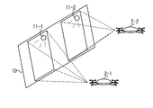
- the laser irradiation apparatus 1 may irradiate a plurality of targets 2 with the coping laser light as shown in FIG.
- the detection information acquired by the detection device 20 includes information on the first target 2-1 and the second target 2-2.
- the control device 30 estimates the position of the first target 2-1 and the position of the second target 2-2 based on the detection information.
- the control device 30 includes a laser oscillator 11 that irradiates the first target 2-1 with a countermeasure laser beam based on the estimated position of the first target 2-1 and a second target 2- based on the estimated position of the second target 2-2.
- the laser oscillator 11 that emits the laser light is determined.
- the control device 30 A coping signal for irradiating the target 2 with coping laser light is transmitted to each laser oscillator 11.
- the laser oscillator 11 irradiates the first target 2-1 or the second target 2-2 with the countermeasure laser light based on the countermeasure signal.
- the control device 30 determines the target 2 to be assigned to this laser oscillator 11. For example, the control device 30 may assign the target 2 having the smallest irradiation angle to the laser oscillator 11.
- the target 2 is the laser oscillator 11 so that the number of the laser oscillators 11 that irradiate the first target 2-1 with the coping laser light is equal to the number of the laser oscillators 11 that irradiate the second target 2-2 with the coping laser light. May be assigned to.
- the control device 30 may determine target 2 to be assigned to the laser oscillator 11 by estimating target information such as the position, speed, acceleration, and traveling direction of the target 2 based on the detection information acquired by the detection device 20. For example, the control device 30 may assign the target 2 having the shortest distance from the laser irradiation device 1 to the laser oscillator 11. The target 2 that reaches the laser irradiation device 1 earliest may be assigned to the laser oscillator 11 based on the position and speed of the target 2. In order to estimate the speed and the like of the target 2, first, the control device 30 estimates the position of the target 2 at each time based on the detection information acquired by the detection device 20 at different times.
- target information such as the position, speed, acceleration, and traveling direction of the target 2 based on the detection information acquired by the detection device 20.
- the control device 30 estimates the speed of the target 2 based on the time when the detection device 20 acquires the detection information and the position of the target 2 at each time.
- the control device 30 may assign the target 2 having the shortest distance from the protection target to the laser oscillator 11.
- the target 2 that reaches the protection target earliest may be assigned to the laser oscillator 11.
- the target information may include types of moving objects such as aircraft, drones, flying objects, and vehicles.
- the control device 30 may estimate the type of the target 2 such as an aircraft, a drone, a flying vehicle, or a vehicle based on the detection information acquired by the detection device 20, and determine the target 2 to be assigned to the laser oscillator 11. In this case, the control device 30 estimates the shape of the target 2 based on the detection information acquired by the detection device 20.
- the control device 30 retrieves the registered shape closest to the estimated shape from the registered registered shapes.
- the type corresponding to the retrieved registered shape is estimated as the type of target 2.
- the priority corresponding to the estimated type is searched, and the target 2 having the highest priority is assigned to the laser oscillator 11.
- the registered shape, the type, and the priority are associated with each other and registered in the control device 30.
- the target information may include the usage and model of the mobile body. In this case, the priority is set to the usage and model of the mobile body.
- the control device 30 may calculate the threat level of the target 2 based on the detection information acquired by the detection device 20 and assign the target 2 having the highest threat level to the laser oscillator 11.
- the threat level is calculated from the type, size, speed, traveling direction, etc. of the target 2.
- the control device 30 may include an input device and assign the target 2 selected by the user to the laser oscillator 11.
- the control device 30 responds to the movement of the target 2 by the control device 30 as shown in FIG.
- the laser oscillator 11 for irradiating with may be changed.
- description will be given using a rectangular coordinate system.
- the in-plane direction of the surface of the laser array 10 will be referred to as the x direction and the y direction, and the normal direction of the surface of the laser array 10 will be described as the z direction.
- the control device 30 when the target 2 moves in the +x direction, the control device 30 causes the second laser oscillator 11-2 arranged in the +x direction of the first laser oscillator 11-1 irradiating the target 2 with the coping laser light. Assign goal 2 to.
- the control device 30 stops the irradiation of the coping laser light by the first laser oscillator 11-1.
- the control device 30 causes the third laser oscillator 11-3 arranged in the +x direction of the second laser oscillator 11-2, which irradiates the target 2 with the coping laser light.
- the control device 30 stops the irradiation of the coping laser light by the second laser oscillator 11-2.
- the laser oscillator 11 when the target 2 moves in the +x direction, the laser oscillator 11 operates as follows. As shown in FIG. 7, the irradiation oscillator 11a of the laser oscillator 11 irradiates the target 2 with the coping laser light. In the laser oscillator 11, the adjacent oscillator 11b arranged in the adjacent region 12 adjacent to the irradiation oscillator 11a does not emit the coping laser light.
- the control device 30 When the target 2 moves in the +x direction, a part of the adjacent oscillator 11b irradiates the target 2 with the coping laser light. Since the target 2 moves in the +x direction, the first adjacent oscillator 11b-1 arranged in the +x direction of the irradiation oscillator 11a irradiates the target 2 with the coping laser beam at the angle irradiated by the irradiation oscillator 11a. You can Therefore, the control device 30 generates the coping signal so that the first adjacent oscillator 11b-1 irradiates the target 2 with the coping laser light. The first adjacent oscillator 11b-1 irradiates the target 2 with the countermeasure laser light based on the countermeasure signal.
- the control device 30 When the target 2 moves in the +x direction, a part of the irradiation oscillator 11a stops irradiation of the coping laser light. Since the target 2 moves in the +x direction, the first irradiation oscillator 11a-1 arranged in the ⁇ x direction, which is the opposite direction to the moving direction of the target 2, is the angle irradiated by the irradiation oscillator 11a. Countermeasure Laser light cannot be emitted. Therefore, the control device 30 generates a coping signal to the first irradiation oscillator 11a-1 so as to stop the irradiation of the coping laser light. The first irradiation oscillator 11a-1 stops the irradiation of the coping laser light based on the coping signal.
- the first adjacent oscillator 11b-1 may emit the coping laser before the first irradiation oscillator 11a-1 stops the irradiation of the coping laser. Further, the first adjacent oscillator 11b-1 may emit the coping laser after the first irradiation oscillator 11a-1 stops the irradiation of the coping laser. The first adjacent oscillator 11b-1 may emit the coping laser at the same time when the first irradiation oscillator 11a-1 stops the irradiation of the coping laser.
- the control device 30 may generate the coping signal to be transmitted to the first adjacent oscillator 11b-1 before generating the coping signal to be transmitted to the first irradiation oscillator 11a-1. Further, the control device 30 may generate the coping signal to be transmitted to the first irradiation oscillator 11a-1 and then generate the coping signal to be transmitted to the first adjacent oscillator 11b-1. The control device 30 may generate the coping signal to be transmitted to the first irradiation oscillator 11a-1 and simultaneously generate the coping signal to be transmitted to the first adjacent oscillator 11b-1.
- the adjacent oscillator 11b arranged in the adjacent region 12 may be controlled so as not to emit the detection laser light.
- the adjacent oscillator 11b can be said to be the laser oscillator 11 that has a high possibility of irradiating the target 2 with the coping laser light.
- the irradiation direction of the detection laser light is controlled so that the whole detection space 600 is irradiated with the detection laser light.
- the shape of the adjacent region 12 may be changed according to the traveling direction, speed, acceleration, etc. of the target 2.
- control device 30 can control the laser oscillator 11 as in the case of moving in the x direction.
- the control device 30 may estimate the estimated route 3 of the target 2 from the detection information and determine the laser oscillator 11 that irradiates the target 2 with the coping laser light based on the estimated route 3. ..
- a laser oscillator 11 irradiating a target 2 with a coping laser is arranged in an irradiation region 13.
- the control device 30 first estimates the estimated route 3 of the target 2. For example, target information such as the position, speed, acceleration, and model of the target 2 is estimated from the detection information acquired by the detection device 20. The estimated route 3 of the target 2 is estimated based on the estimated target information of the target 2.
- the control device 30 determines the laser oscillator 11 that irradiates the target 2 with the coping laser light at a desired time based on the estimated route 3. For example, the control device 30 estimates the estimated position 4 of the target 2 at a desired time, for example, the first estimated position 4-1 and the second estimated position 4-2, based on the estimated route 3 of the target 2. Based on the first estimated position 4-1, a laser oscillator 11 that emits a countermeasure laser light when the target 2 reaches the first estimated position 4-1 (for example, a laser arranged in the first estimated irradiation region 14-1). The oscillator 11) is determined.
- the laser oscillator 11 that irradiates the countermeasure laser light when the target 2 reaches the second estimated position 4-2 (for example, disposed in the second estimated irradiation region 14-2).
- the laser oscillator 11 is selected.
- the control device 30 determines a schedule for the laser oscillator 11 to irradiate the target 2 with the coping laser light, and controls the laser oscillator 11 based on the schedule.
- the control device 30 determines a schedule in which each laser oscillator 11 irradiates the coping laser light based on the time when the target 2 reaches the estimated position 4 and the laser oscillator 11 arranged in the estimated irradiation region 14. According to this schedule, the control device 30 generates a coping signal for controlling the laser oscillator 11. For example, at the time when the target 2 reaches the first estimated position 4-1, a coping signal is transmitted to the laser oscillator 11 arranged in the first estimated irradiation region 14-1. As a result, the laser oscillator 11 irradiates the target 2 with the coping laser light according to the determined schedule.
- control device 30 may determine the schedule for irradiating the target 2 with the coping laser light by estimating the estimated route 3 of the target 2. This schedule may be updated when the detection device 20 acquires the detection information.
- the laser oscillator 11 that irradiates each target 2 with the countermeasure laser light may be determined.
- the control device 30 may select the laser oscillator 11 that emits the detection laser light so that images such as characters and pictures are displayed on the laser array 10. For example, the control device 30 determines an area (for example, an area occupied by the character, an area occupied by the edge of the character, etc.) that matches the shape of the character “AAA” in the laser array 10. The control device 30 selects the laser oscillator 11 arranged in this region as a laser oscillator group and transmits a detection signal indicating that the selected laser oscillator group is irradiated with the detection laser light. The laser oscillator 11 included in the laser oscillator group emits the output laser light 501 as detection laser light based on the detection signal.
- an area for example, an area occupied by the character, an area occupied by the edge of the character, etc.
- the control device 30 selects the laser oscillator 11 arranged in this region as a laser oscillator group and transmits a detection signal indicating that the selected laser oscillator group is irradiated with the
- a laser beam group including the output laser beam 501 emitted by each laser oscillator 11 is emitted.
- the characters "AAA" are displayed.
- the detection laser light is reflected by the target 2 and reaches the detection device 20.
- the detection device 20 can detect the target 2. In this way, the laser array 10 can detect the target 2 while displaying characters.
- the direction in which the detection laser light is emitted can be arbitrarily selected according to the direction in which the image is displayed on the laser array 10. For example, when displaying images in a plurality of directions, the corresponding laser oscillator 11 emits the detection laser light in a plurality of directions. For example, by setting the interval of irradiating the detection laser light in a predetermined direction to 1/25 second, when the laser array 10 is viewed from this direction, an image on the laser array 10 is displayed. When some of the laser oscillators 11 selected according to the image emit the detection laser light in the first direction, the other laser oscillators 11 emit the detection laser light in a direction different from the first direction. It may be irradiated.
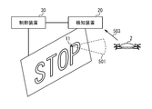
- the controller 30 may change the image displayed on the laser array 10 according to the direction in which the laser array 10 is viewed, as shown in FIG.
- the control device 30 controls the laser oscillator 11 so as to irradiate the laser light group in accordance with the shape of the character string “AAA” in the first direction. Specifically, the control device 30 determines an area on the laser array 10 according to the shape of the character string “AAA”, and selects the laser oscillator 11 arranged in this area as the first laser oscillator group. The selected first laser oscillator group irradiates the first output laser light 501-1 as the detection laser light in the first direction in accordance with the instruction from the control device 30. As a result, when the laser array 10 is viewed from the first direction, the character string "AAA" is displayed.
- the control device 30 controls the laser oscillator 11 so as to irradiate the laser light group in accordance with the shape of the character string “BBB” in the second direction different from the first direction. Specifically, the control device 30 determines a region on the laser array 10 according to the shape of the character string “BBB”, and selects the laser oscillator 11 arranged in this region as the second laser oscillator group. The selected second laser oscillator group irradiates the second output laser light 501-2 as the detection laser light in the second direction according to the instruction from the control device 30. As a result, when the laser array 10 is viewed from the second direction, the character string "BBB" is displayed.
- the laser oscillator 11 included in both the first laser oscillator group and the second laser oscillator group irradiates the detection laser light in the first direction and the second direction. Thereby, one laser array 10 can display different images in a plurality of directions.
- the controller 30 may control the laser oscillator 11 by software processing.
- the control device 30 includes a calculation device 31 and a storage device 32, as shown in FIG. 11.
- the storage device 32 stores various data used for controlling the laser oscillator 11.
- the laser irradiation software 33 is installed in the storage device 32, and the storage device 32 is used as a non-transitory tangible storage medium for storing the laser irradiation software 33.
- the laser irradiation software 33 may be provided as a computer program product recorded on a computer-readable storage medium 40, or may be provided as a computer program product downloadable from a server.
- the arithmetic unit 31 executes the laser irradiation software 33 to perform various data processing for controlling the laser oscillator 11.
- the arithmetic unit 31 generates a detection signal and a coping signal for controlling the laser oscillator 11, and estimates the position of the target 2.
- the laser oscillator 11 emits detection laser light based on the detection signal.
- the arithmetic device 31 estimates the position of the target 2 based on the reflected light 503 of the detection laser light detected by the detection device 20.
- the arithmetic unit 31 generates a coping signal based on the estimated position.
- the laser oscillator 11 irradiates the target 2 with the countermeasure laser light based on the countermeasure signal.
- the laser oscillator 11 includes an optical element 100 and a laser element 200, for example, as shown in FIG.
- the laser element 200 is provided around the optical element 100, and is configured to irradiate the input light 101 of the optical element 100 with the seed light 500 from a plurality of directions.
- the optical element 100 is configured to irradiate the seed light 500 applied to the input surface 101 as the output laser light 501 from the output surface 102.
- the direction in which the output laser beam 501 is irradiated is determined by the wavelength and the irradiation direction of the seed light 500 that the laser element 200 irradiates the optical element 100.
- the wavelength and the irradiation direction of the seed light 500 are configured to be controlled by the control device 30.
- the seed light 500 includes a first seed light 500-1 (not shown), a second seed light 500-2 (not shown),..., An Nth seed light 500-N (not shown), which have different irradiation directions. ) Is a generic term.
- the output laser light 501 includes a first output laser light 501-1 (not shown) and a second output laser light 501-2 (not shown) that are emitted when the seed light 500 is applied to the optical element 100. ),..., A general term for the Nth output laser light 501-N.
- the optical element 100 When the optical element 100 is irradiated with the first-type light 500-1, the optical element 100 irradiates the first output laser beam 501-1.
- the optical element 100 When the optical element 100 is irradiated with the second type light 500-2, the optical element 100 irradiates the second output laser beam 501-2. When the optical element 100 is irradiated with the N-type light 500-N, the optical element 100 irradiates the N-th output laser light 501-N.
- the optical element 100 has, for example, a cylindrical shape, and has an input surface 101 and an output surface 102 on one bottom surface.
- the input surface 101 is, for example, a flat surface provided at an end portion of the bottom surface, and is configured such that the seed light 500 is emitted from the laser element 200.
- the output surface 102 is a flat surface provided on the bottom surface, and is configured to emit the output laser light 501.
- the output surface 102 may be formed in a circular shape at the center of the bottom surface, for example.
- the optical element 100 is formed by sequentially stacking a second reflecting mirror 120, an active layer 130, a first reflecting mirror 140, and a first electrode 150 on one surface of a substrate 110.
- the boundary of each layer is provided, for example, in parallel with the bottom surface of the optical element 100, for example, the output surface 102.
- the second electrode 160 is provided adjacent to the other surface of the substrate 110.
- the first reflecting mirror 140 has, for example, the input surface 101 at the end of the surface.
- the seed light 500 emitted from the laser element 200 enters the first reflecting mirror 140 from the input surface 101.
- the input surface 101 is configured to have a lower reflectance than other portions of the surface of the first reflecting mirror 140.
- the first reflecting mirror 140 is formed such that the thickness of the first reflecting mirror 140 at the position where the input surface 101 is provided is thinner than the thickness of the first reflecting mirror 140 at other positions.
- the input surface 101 is, for example, a plane parallel to the output surface 102.
- the laser light incident from the input surface 101 travels inside the optical element 100 as a propagating laser light 502.
- the propagating laser light 502 is the first propagating laser light 502-1, the second propagating laser light 502-2,...,
- the optical element 100 is irradiated with the first-type light 500-1, it propagates through the optical element 100 as the first propagating laser light 502-1.
- the optical element 100 is irradiated with the second type light 500-2, it travels inside the optical element 100 as the second propagating laser beam 502-2.
- the optical element 100 is irradiated with the N-type light 500-N, it travels inside the optical element 100 as the N-th propagation laser light 502-N.
- the first reflecting mirror 140 and the second reflecting mirror 120 are provided so as to face each other, and a waveguide 170 (planer wave guide) is formed between the first reflecting mirror 140 and the second reflecting mirror 120.
- the second reflecting mirror 120 reflects the propagating laser light 502 incident from the input surface 101. A part of the propagating laser light 502 reflected by the second reflecting mirror 120 is reflected by the first reflecting mirror 140.
- the propagating laser light 502 reflected by the first reflecting mirror 140 is reflected by the second reflecting mirror 120. In this way, the propagating laser light 502 is sequentially reflected by the first reflecting mirror 140 and the second reflecting mirror 120 and travels through the waveguide 170.
- the first reflecting mirror 140 and the second reflecting mirror 120 are formed to perform Bragg reflection, and include, for example, a distributed Bragg reflector (DBR).
- DBR distributed Bragg reflector
- the first reflecting mirror 140 passes a part of the propagating laser beam 502 and reflects the other part.
- the propagating laser light 502 reflected by the first reflecting mirror 140 travels inside the optical element 100.
- the propagating laser light 502 that has passed through the first reflecting mirror 140 is emitted as the output laser light 501 from the output surface 102 formed on the surface of the first reflecting mirror 140.
- the second reflecting mirror 120 may reflect all of the propagating laser light 502. Therefore, the reflectance of the first reflecting mirror 140 may be lower than the reflectance of the second reflecting mirror 120. For example, the thickness of the first reflecting mirror 140 may be thinner than the thickness of the second reflecting mirror 120.
- the active layer 130 is provided between the first reflecting mirror 140 and the second reflecting mirror 120, and amplifies the propagating laser light 502 passing through the active layer 130.
- the propagating laser light 502 travels through the waveguide 170, part of the propagating laser light 502 is emitted as the output laser light 501, and the other part of the propagating laser light 502 is amplified by the active layer 130.
- the active layer 130 is excited by the current flowing between the first electrode 150 and the second electrode 160.
- the active layer 130 may be excited until it emits light.
- the first electrode 150 and the second electrode 160 are provided so as to sandwich the active layer 130.
- the first electrode 150 and the second electrode 160 are connected to the control device 30.
- the controller 30 causes a current to flow between the first electrode 150 and the second electrode 160 to excite the active layer 130.
- the control device 30 adjusts the amplification of the propagating laser light 502 by the active layer 130 by controlling the current flowing through the active layer 130.
- the first electrode 150 is formed so as not to overlap the input surface 101 irradiated with the seed light 500 and the output surface 102 irradiated with the output laser light 501.
- the input surface 101 is provided at the end of the optical element 100 in the direction in which the seed light 500 is emitted.
- the output surface 102 is formed in a circular shape at the center of the bottom surface of the optical element 100, for example.
- the optical element 100 propagates the propagating laser light 502 along the waveguide 170 provided between the first reflecting mirror 140 and the second reflecting mirror 120, and outputs the output laser light 501 from the output surface 102. Irradiate.
- the optical element 100 includes, for example, a vertical cavity surface emitting laser (VCSEL).
- VCSEL vertical cavity surface emitting laser
- the diameter of the output surface 102 of the optical element 100 may be 1 cm.
- the laser device 200 includes, for example, a plurality of seed light sources 240 (first seed light source 240-1, second seed light source 240-2,..., N seed light source 240-N).
- the seed light source 240 irradiates the optical element 100 with the seed light 500.
- each of the seed light sources 240 emits the seed light 500 in different directions and emits the first seed light 500-1, the second seed light 500-2,..., The Nth seed light 500-N.
- the first type light source 240-1 irradiates the optical element 100 with the first type light 500-1.
- the second-type light source 240-2 irradiates the optical element 100 with the second-type light 500-2.
- the N-type light source 240-N irradiates the optical element 100 with the N-type light 500-N.
- the first seed light source 240-1 and the second seed light source 240-2 may emit the seed light 500 in the same direction.
- the seed light source 240 may be configured to be connected to a device that outputs the seed light 500 via an optical switch and irradiate the seed light 500 output by this device.
- the optical switch selects the seed light source 240 that emits the seed light 500.
- the seed light source 240 include a collimator and a fiber array in which optical fibers are bundled.
- the seed light source 240 is arranged so as to surround the optical element 100.
- the seed light sources 240 are arranged so as to surround, for example, half of the optical element 100 when viewed in the normal direction of the output surface 102, and the seed light sources 240 are arranged at equal intervals.
- a spherical coordinate system whose origin is the center of the output surface 102 will be described.
- the distance from the origin is a radius r (radius)
- the angle from the normal line 510 of the output surface 102 is a polar angle ⁇ (polar angle)
- the direction when viewed from the origin in the in-plane direction of the output surface 102 ⁇ (azimuthal).
- the laser element 200 irradiates the optical element 100 with seed light 500 from, for example, an i-th type light source 240-i and a k-th type light source 240-k.
- the azimuths ⁇ of the irradiation directions of the seed light 500 emitted by the i-th type light source 240-i and the k-th type light source 240-k are not parallel to each other.
- the input surface 101 is a plane, the azimuth ⁇ of the traveling direction of the i-th propagated laser light 502-i corresponding to the i-th seed light 500-i and the k-th propagated laser light corresponding to the k-th seed light 500-k.
- the azimuth ⁇ of the traveling direction of 502-k is not parallel to each other.
- the output surface 102 is a plane, the azimuth ⁇ of the irradiation direction of the i-th output laser light 501-i corresponding to the i-th propagation laser light 502-i and the k-th output corresponding to the k-th propagation laser light 502-k.
- the direction ⁇ of the irradiation direction of the laser light 501-k is not parallel to each other.
- the azimuth ⁇ of the irradiation direction of the output laser light 501 when the seed light 500 is emitted from the i-th seed light source 240-i and the output laser when the seed light 500 is emitted from the k-th seed light source 240-k The direction ⁇ of the irradiation direction of the light 501 is different.
- the laser oscillator 11 can control the azimuth ⁇ of the irradiation direction of the output laser light 501 by changing the seed light source 240 that irradiates the seed light 500. It can be said that the direction ⁇ in the irradiation direction of the output laser beam 501 can be controlled by irradiating the laser element 200 with a plurality of seed lights 500 in which the direction ⁇ in the traveling direction is not parallel to each other in the waveguide 170.
- the plurality of optical paths of the propagating laser light 502 which are emitted from the plurality of seed light sources 240 and proceed inside the optical element 100 are the waveguides 170 formed in the optical element 100 when viewed from the normal direction of the output surface. They may cross each other inside.
- the optical path of the i-th propagating laser light 502-i and the optical path of the k-th propagating laser light 502-k may intersect inside the waveguide 170 when viewed from the direction normal to the output surface. ..
- the two seed light sources 240 of the plurality of seed light sources 240 may irradiate the optical element 100 with the seed light 500 from parallel directions.
- the polar angle ⁇ of the irradiation direction of the output laser light 501 can be changed.
- the seed light 500 is applied to the input surface 101 from a direction inclined with respect to the normal line direction of the input surface 101, and is guided into the optical element 100 as the propagating laser light 502.
- the propagating laser light 502 is reflected by the first reflecting mirror 140 and the second reflecting mirror 120.
- the incident angle 506 of the propagating laser light 502 on the first reflecting mirror 140 is ⁇ i , the following formula (1) is established based on Bragg's law.
- the incident angle 506 indicates the angle between the incident direction of the propagating laser beam 502 on the first reflecting mirror 140 and the normal line 510 of the output surface 102. Further, ⁇ represents the wavelength of the propagating laser light 502, and ⁇ c represents the cutoff wavelength of the waveguide 170.
- the first reflecting mirror 140 allows a part of the propagating laser light 502 incident at an incident angle 506 to pass as the output laser light 501.
- the output laser beam 501 is refracted and irradiated on the output surface 102 provided on the first reflecting mirror 140. Since the wavelength of the output laser light 501 is the same as the wavelength of the propagating laser light 502, if an output angle 505 that represents an angle between the irradiation direction of the output laser light 501 and the normal line 510 of the output surface 102 is ⁇ o , The following expression (2) is established.
- n air represents the refractive index in the atmosphere
- n wg represents the refractive index of the waveguide 170.
- the output angle 505 changes based on the wavelength of the seed light 500. Since the output angle 505 indicates the polar angle ⁇ in the direction in which the output laser beam 501 is irradiated, the polar angle ⁇ in the direction in which the output laser beam 501 is irradiated is changed based on the wavelength of the seed light 500. As a result, the laser oscillator 11 can control the polar angle ⁇ of the irradiation direction of the output laser light 501 by changing the wavelength of the seed light 500.
- the laser oscillator 11 controls the seed light source 240 that emits the seed light 500 and the wavelength of the laser light that the seed light source 240 irradiates, so that the direction of the output laser light 501 that is emitted is non-mechanical. , And can be changed two-dimensionally.
- the laser oscillator 11 sets the polar angle and the azimuth of the irradiation direction of the laser light in a spherical coordinate system in which the position where the laser light is output is the origin and the direction where the laser light is irradiated is the apex (zenith). Can be changed.
- the control device 30 controls the irradiation direction of the output laser light 501 by selecting the wavelength of the seed light 500 and the seed light source 240. be able to.
- the output energy of the output laser light 501 is adjusted by the control device 30 controlling the current flowing between the first electrode 150 and the second electrode 160 and the output energy of the seed light 500.
- the directions in which the laser oscillators 11 can emit the output laser light 501 do not have to be the same.
- the directions in which the adjacent laser oscillators 11 can emit the output laser light 501 may be different.
- the irradiation directions can be complemented by the fact that the adjacent laser oscillators 11 can irradiate the output laser light 501 with different directions. As a result, the direction in which the laser array 10 can emit the output laser light 501 can be widened.
- the present invention has been described with reference to the exemplary embodiments and examples, the present invention is not limited to the above-described exemplary embodiments and examples.
- the configuration and details of the present invention can be appropriately modified or changed by those skilled in the art within the scope of the technical idea of the present invention described in the claims.
- the above-described embodiments and examples may be combined within a technically consistent range.
- the processing described above is an example, and the order of each step and the processing content may be changed within a range that does not hinder the function.
- the configuration described may be arbitrarily changed within the range not impairing the function.
Landscapes
- Physics & Mathematics (AREA)
- Engineering & Computer Science (AREA)
- Electromagnetism (AREA)
- General Physics & Mathematics (AREA)
- Remote Sensing (AREA)
- Radar, Positioning & Navigation (AREA)
- Computer Networks & Wireless Communication (AREA)
- Optics & Photonics (AREA)
- Condensed Matter Physics & Semiconductors (AREA)
- General Engineering & Computer Science (AREA)
- Lasers (AREA)
- Optical Radar Systems And Details Thereof (AREA)
- Length Measuring Devices By Optical Means (AREA)
- Control Of Indicators Other Than Cathode Ray Tubes (AREA)
Priority Applications (3)
| Application Number | Priority Date | Filing Date | Title |
|---|---|---|---|
| EP22162930.6A EP4036604B1 (en) | 2019-01-25 | 2019-09-03 | Laser irradiation apparatus |
| EP19911400.0A EP3822664A4 (en) | 2019-01-25 | 2019-09-03 | LASER IRRADIATION DEVICE AND STORAGE MEDIA FOR STORING A LASER IRRADIATION PROGRAM |
| US17/268,701 US12085368B2 (en) | 2019-01-25 | 2019-09-03 | Laser irradiation apparatus and storage medium storing laser irradiation program |
Applications Claiming Priority (2)
| Application Number | Priority Date | Filing Date | Title |
|---|---|---|---|
| JP2019011203A JP7182334B2 (ja) | 2019-01-25 | 2019-01-25 | レーザ照射装置及びレーザ照射プログラム |
| JP2019-011203 | 2019-01-25 |
Publications (1)
| Publication Number | Publication Date |
|---|---|
| WO2020152903A1 true WO2020152903A1 (ja) | 2020-07-30 |
Family
ID=71736212
Family Applications (1)
| Application Number | Title | Priority Date | Filing Date |
|---|---|---|---|
| PCT/JP2019/034541 Ceased WO2020152903A1 (ja) | 2019-01-25 | 2019-09-03 | レーザ照射装置及びレーザ照射プログラムを格納する記憶媒体 |
Country Status (4)
| Country | Link |
|---|---|
| US (1) | US12085368B2 (enExample) |
| EP (2) | EP3822664A4 (enExample) |
| JP (1) | JP7182334B2 (enExample) |
| WO (1) | WO2020152903A1 (enExample) |
Families Citing this family (3)
| Publication number | Priority date | Publication date | Assignee | Title |
|---|---|---|---|---|
| JP2023059363A (ja) * | 2021-10-15 | 2023-04-27 | 三菱重工業株式会社 | 脅威対処システム及び脅威対処プログラム |
| JP2023064936A (ja) * | 2021-10-27 | 2023-05-12 | 三菱重工業株式会社 | 脅威対処システムおよび脅威対処方法 |
| CN119063582B (zh) * | 2024-11-05 | 2025-02-07 | 浙江大学海南研究院 | 移动式激光拒止防御系统 |
Citations (7)
| Publication number | Priority date | Publication date | Assignee | Title |
|---|---|---|---|---|
| JP2010127818A (ja) | 2008-11-28 | 2010-06-10 | Mitsubishi Electric Corp | レーザー照射装置 |
| JP2013016591A (ja) | 2011-07-01 | 2013-01-24 | Denso Corp | 光偏向素子および光偏向モジュール |
| JP2014098873A (ja) * | 2012-11-16 | 2014-05-29 | Olympus Corp | 表示装置 |
| JP2017072557A (ja) * | 2015-10-09 | 2017-04-13 | 三菱重工業株式会社 | 飛行物体探知システム及び飛行物体探知方法 |
| JP2017157609A (ja) | 2016-02-29 | 2017-09-07 | 国立大学法人東京工業大学 | ビーム偏向デバイス |
| CN107514936A (zh) * | 2017-09-30 | 2017-12-26 | 合肥正阳光电科技有限责任公司 | 一种近程激光防御系统 |
| JP2019011203A (ja) | 2018-09-27 | 2019-01-24 | 株式会社ナベル | 自動倉庫の制御装置 |
Family Cites Families (12)
| Publication number | Priority date | Publication date | Assignee | Title |
|---|---|---|---|---|
| AU7811881A (en) * | 1980-12-09 | 1982-06-17 | John Leonard Hughes | Variable beamwidth laser radar systems |
| US6414746B1 (en) * | 1999-11-24 | 2002-07-02 | Advanced Scientific Concepts, Inc. | 3-D imaging multiple target laser radar |
| US6396577B1 (en) * | 2001-03-19 | 2002-05-28 | Thomas P. Ramstack | Lidar-based air defense system |
| US6939012B2 (en) | 2003-06-02 | 2005-09-06 | Eastman Kodak Company | Laser image projector |
| US8301027B2 (en) * | 2008-05-02 | 2012-10-30 | Massachusetts Institute Of Technology | Agile-beam laser array transmitter |
| US9292757B1 (en) | 2013-10-08 | 2016-03-22 | American Megatrends, Inc. | Laser projection system projecting content based on information collected from nearby targets |
| US20160377414A1 (en) | 2015-06-23 | 2016-12-29 | Hand Held Products, Inc. | Optical pattern projector |
| CN105372827A (zh) | 2015-10-22 | 2016-03-02 | 北京工业大学 | 一种消除激光显示散斑的方法及激光光源 |
| JP6888813B2 (ja) | 2017-04-26 | 2021-06-16 | 国立研究開発法人宇宙航空研究開発機構 | 人工衛星、明点表示方法、情報提供方法、及びプログラム |
| CN107121017A (zh) * | 2017-05-04 | 2017-09-01 | 成都安的光电科技有限公司 | 一种无人机狙击系统 |
| WO2018220382A1 (en) | 2017-06-02 | 2018-12-06 | Bae Systems Plc | Weapon system |
| CN207051590U (zh) * | 2017-07-04 | 2018-02-27 | 成都安的光电科技有限公司 | 激光扩束装置及无人机激光狙击系统 |
-
2019
- 2019-01-25 JP JP2019011203A patent/JP7182334B2/ja active Active
- 2019-09-03 EP EP19911400.0A patent/EP3822664A4/en active Pending
- 2019-09-03 US US17/268,701 patent/US12085368B2/en active Active
- 2019-09-03 WO PCT/JP2019/034541 patent/WO2020152903A1/ja not_active Ceased
- 2019-09-03 EP EP22162930.6A patent/EP4036604B1/en active Active
Patent Citations (7)
| Publication number | Priority date | Publication date | Assignee | Title |
|---|---|---|---|---|
| JP2010127818A (ja) | 2008-11-28 | 2010-06-10 | Mitsubishi Electric Corp | レーザー照射装置 |
| JP2013016591A (ja) | 2011-07-01 | 2013-01-24 | Denso Corp | 光偏向素子および光偏向モジュール |
| JP2014098873A (ja) * | 2012-11-16 | 2014-05-29 | Olympus Corp | 表示装置 |
| JP2017072557A (ja) * | 2015-10-09 | 2017-04-13 | 三菱重工業株式会社 | 飛行物体探知システム及び飛行物体探知方法 |
| JP2017157609A (ja) | 2016-02-29 | 2017-09-07 | 国立大学法人東京工業大学 | ビーム偏向デバイス |
| CN107514936A (zh) * | 2017-09-30 | 2017-12-26 | 合肥正阳光电科技有限责任公司 | 一种近程激光防御系统 |
| JP2019011203A (ja) | 2018-09-27 | 2019-01-24 | 株式会社ナベル | 自動倉庫の制御装置 |
Non-Patent Citations (1)
| Title |
|---|
| See also references of EP3822664A4 |
Also Published As
| Publication number | Publication date |
|---|---|
| JP7182334B2 (ja) | 2022-12-02 |
| EP4036604A1 (en) | 2022-08-03 |
| US12085368B2 (en) | 2024-09-10 |
| EP3822664A1 (en) | 2021-05-19 |
| EP3822664A4 (en) | 2021-11-24 |
| US20210231414A1 (en) | 2021-07-29 |
| JP2020118595A (ja) | 2020-08-06 |
| EP4036604B1 (en) | 2024-10-23 |
Similar Documents
| Publication | Publication Date | Title |
|---|---|---|
| JPH02707Y2 (enExample) | ||
| EP3430428B1 (en) | Integrated illumination and detection for lidar based 3-d imaging | |
| JP7073262B2 (ja) | 遠視野において重なり合う照射を有するlidarに基づく三次元撮像 | |
| WO2020152903A1 (ja) | レーザ照射装置及びレーザ照射プログラムを格納する記憶媒体 | |
| US9240001B2 (en) | Systems and methods for vehicle survivability planning | |
| US9030347B2 (en) | Preemptive signature control for vehicle survivability planning | |
| US20150204977A1 (en) | Object detection device and sensing apparatus | |
| JP2018514780A (ja) | 距離センサ | |
| US10684358B2 (en) | Situational awareness sensor using a fixed configuration of optical phased arrays (OPAs) | |
| CN108375762B (zh) | 激光雷达及其工作方法 | |
| JP7016796B2 (ja) | 情報処理装置、および情報処理方法 | |
| US20190324145A1 (en) | Lidar Apparatus and Method | |
| US20220051566A1 (en) | Multiple object collision avoidance based on centralized coordination of vehicle operations | |
| IT9048264A1 (it) | Rivelatore di fili sospesi, particolarmente idoneo per applicazioni avioniche | |
| CA3100215C (en) | Multiple mirror monostatic scanning lidar optical ranging sensor | |
| US20170307874A1 (en) | Scanning Optical System And Radar | |
| RU2639321C1 (ru) | Оптико-электронная система обнаружения объектов | |
| EP4152046A1 (en) | Multi-fiber optical sensor for light aircraft | |
| JP7510641B2 (ja) | 3次元センシングシステム | |
| CN112835016B (zh) | 面阵激光雷达、激光器模块及探测器模块 | |
| JP2018155658A (ja) | 物体検出装置、物体検出方法、および物体検出プログラム | |
| CN120380375A (zh) | 一种发射装置、探测装置及终端 | |
| TWI465754B (zh) | 可全角度平面掃描之自走式機器人及其雷射測距模組 | |
| RU2019143312A (ru) | Лидарные (lidar) способы и системы со сканированием с избирательной плотностью на основе mems | |
| US12292534B2 (en) | LiDAR systems for near-field and far-field detection, and related methods and apparatus |
Legal Events
| Date | Code | Title | Description |
|---|---|---|---|
| 121 | Ep: the epo has been informed by wipo that ep was designated in this application |
Ref document number: 19911400 Country of ref document: EP Kind code of ref document: A1 |
|
| ENP | Entry into the national phase |
Ref document number: 2019911400 Country of ref document: EP Effective date: 20210209 |
|
| NENP | Non-entry into the national phase |
Ref country code: DE |