WO2020152864A1 - Vehicle interior material - Google Patents
Vehicle interior material Download PDFInfo
- Publication number
- WO2020152864A1 WO2020152864A1 PCT/JP2019/002537 JP2019002537W WO2020152864A1 WO 2020152864 A1 WO2020152864 A1 WO 2020152864A1 JP 2019002537 W JP2019002537 W JP 2019002537W WO 2020152864 A1 WO2020152864 A1 WO 2020152864A1
- Authority
- WO
- WIPO (PCT)
- Prior art keywords
- layer
- film layer
- core layer
- strain
- film
- Prior art date
Links
Images


Classifications
-
- B—PERFORMING OPERATIONS; TRANSPORTING
- B32—LAYERED PRODUCTS
- B32B—LAYERED PRODUCTS, i.e. PRODUCTS BUILT-UP OF STRATA OF FLAT OR NON-FLAT, e.g. CELLULAR OR HONEYCOMB, FORM
- B32B3/00—Layered products comprising a layer with external or internal discontinuities or unevennesses, or a layer of non-planar form; Layered products having particular features of form
- B32B3/10—Layered products comprising a layer with external or internal discontinuities or unevennesses, or a layer of non-planar form; Layered products having particular features of form characterised by a discontinuous layer, i.e. formed of separate pieces of material
- B32B3/12—Layered products comprising a layer with external or internal discontinuities or unevennesses, or a layer of non-planar form; Layered products having particular features of form characterised by a discontinuous layer, i.e. formed of separate pieces of material characterised by a layer of regularly- arranged cells, e.g. a honeycomb structure
-
- B—PERFORMING OPERATIONS; TRANSPORTING
- B32—LAYERED PRODUCTS
- B32B—LAYERED PRODUCTS, i.e. PRODUCTS BUILT-UP OF STRATA OF FLAT OR NON-FLAT, e.g. CELLULAR OR HONEYCOMB, FORM
- B32B1/00—Layered products having a general shape other than plane
-
- B—PERFORMING OPERATIONS; TRANSPORTING
- B32—LAYERED PRODUCTS
- B32B—LAYERED PRODUCTS, i.e. PRODUCTS BUILT-UP OF STRATA OF FLAT OR NON-FLAT, e.g. CELLULAR OR HONEYCOMB, FORM
- B32B15/00—Layered products comprising a layer of metal
- B32B15/04—Layered products comprising a layer of metal comprising metal as the main or only constituent of a layer, which is next to another layer of the same or of a different material
- B32B15/06—Layered products comprising a layer of metal comprising metal as the main or only constituent of a layer, which is next to another layer of the same or of a different material of natural rubber or synthetic rubber
-
- B—PERFORMING OPERATIONS; TRANSPORTING
- B32—LAYERED PRODUCTS
- B32B—LAYERED PRODUCTS, i.e. PRODUCTS BUILT-UP OF STRATA OF FLAT OR NON-FLAT, e.g. CELLULAR OR HONEYCOMB, FORM
- B32B15/00—Layered products comprising a layer of metal
- B32B15/04—Layered products comprising a layer of metal comprising metal as the main or only constituent of a layer, which is next to another layer of the same or of a different material
- B32B15/08—Layered products comprising a layer of metal comprising metal as the main or only constituent of a layer, which is next to another layer of the same or of a different material of synthetic resin
- B32B15/085—Layered products comprising a layer of metal comprising metal as the main or only constituent of a layer, which is next to another layer of the same or of a different material of synthetic resin comprising polyolefins
-
- B—PERFORMING OPERATIONS; TRANSPORTING
- B32—LAYERED PRODUCTS
- B32B—LAYERED PRODUCTS, i.e. PRODUCTS BUILT-UP OF STRATA OF FLAT OR NON-FLAT, e.g. CELLULAR OR HONEYCOMB, FORM
- B32B15/00—Layered products comprising a layer of metal
- B32B15/04—Layered products comprising a layer of metal comprising metal as the main or only constituent of a layer, which is next to another layer of the same or of a different material
- B32B15/08—Layered products comprising a layer of metal comprising metal as the main or only constituent of a layer, which is next to another layer of the same or of a different material of synthetic resin
- B32B15/088—Layered products comprising a layer of metal comprising metal as the main or only constituent of a layer, which is next to another layer of the same or of a different material of synthetic resin comprising polyamides
-
- B—PERFORMING OPERATIONS; TRANSPORTING
- B32—LAYERED PRODUCTS
- B32B—LAYERED PRODUCTS, i.e. PRODUCTS BUILT-UP OF STRATA OF FLAT OR NON-FLAT, e.g. CELLULAR OR HONEYCOMB, FORM
- B32B15/00—Layered products comprising a layer of metal
- B32B15/04—Layered products comprising a layer of metal comprising metal as the main or only constituent of a layer, which is next to another layer of the same or of a different material
- B32B15/08—Layered products comprising a layer of metal comprising metal as the main or only constituent of a layer, which is next to another layer of the same or of a different material of synthetic resin
- B32B15/09—Layered products comprising a layer of metal comprising metal as the main or only constituent of a layer, which is next to another layer of the same or of a different material of synthetic resin comprising polyesters
-
- B—PERFORMING OPERATIONS; TRANSPORTING
- B32—LAYERED PRODUCTS
- B32B—LAYERED PRODUCTS, i.e. PRODUCTS BUILT-UP OF STRATA OF FLAT OR NON-FLAT, e.g. CELLULAR OR HONEYCOMB, FORM
- B32B15/00—Layered products comprising a layer of metal
- B32B15/18—Layered products comprising a layer of metal comprising iron or steel
-
- B—PERFORMING OPERATIONS; TRANSPORTING
- B32—LAYERED PRODUCTS
- B32B—LAYERED PRODUCTS, i.e. PRODUCTS BUILT-UP OF STRATA OF FLAT OR NON-FLAT, e.g. CELLULAR OR HONEYCOMB, FORM
- B32B15/00—Layered products comprising a layer of metal
- B32B15/20—Layered products comprising a layer of metal comprising aluminium or copper
-
- B—PERFORMING OPERATIONS; TRANSPORTING
- B32—LAYERED PRODUCTS
- B32B—LAYERED PRODUCTS, i.e. PRODUCTS BUILT-UP OF STRATA OF FLAT OR NON-FLAT, e.g. CELLULAR OR HONEYCOMB, FORM
- B32B25/00—Layered products comprising a layer of natural or synthetic rubber
- B32B25/04—Layered products comprising a layer of natural or synthetic rubber comprising rubber as the main or only constituent of a layer, which is next to another layer of the same or of a different material
- B32B25/045—Layered products comprising a layer of natural or synthetic rubber comprising rubber as the main or only constituent of a layer, which is next to another layer of the same or of a different material of foam
-
- B—PERFORMING OPERATIONS; TRANSPORTING
- B32—LAYERED PRODUCTS
- B32B—LAYERED PRODUCTS, i.e. PRODUCTS BUILT-UP OF STRATA OF FLAT OR NON-FLAT, e.g. CELLULAR OR HONEYCOMB, FORM
- B32B25/00—Layered products comprising a layer of natural or synthetic rubber
- B32B25/04—Layered products comprising a layer of natural or synthetic rubber comprising rubber as the main or only constituent of a layer, which is next to another layer of the same or of a different material
- B32B25/06—Layered products comprising a layer of natural or synthetic rubber comprising rubber as the main or only constituent of a layer, which is next to another layer of the same or of a different material of paper or cardboard
-
- B—PERFORMING OPERATIONS; TRANSPORTING
- B32—LAYERED PRODUCTS
- B32B—LAYERED PRODUCTS, i.e. PRODUCTS BUILT-UP OF STRATA OF FLAT OR NON-FLAT, e.g. CELLULAR OR HONEYCOMB, FORM
- B32B25/00—Layered products comprising a layer of natural or synthetic rubber
- B32B25/04—Layered products comprising a layer of natural or synthetic rubber comprising rubber as the main or only constituent of a layer, which is next to another layer of the same or of a different material
- B32B25/08—Layered products comprising a layer of natural or synthetic rubber comprising rubber as the main or only constituent of a layer, which is next to another layer of the same or of a different material of synthetic resin
-
- B—PERFORMING OPERATIONS; TRANSPORTING
- B32—LAYERED PRODUCTS
- B32B—LAYERED PRODUCTS, i.e. PRODUCTS BUILT-UP OF STRATA OF FLAT OR NON-FLAT, e.g. CELLULAR OR HONEYCOMB, FORM
- B32B25/00—Layered products comprising a layer of natural or synthetic rubber
- B32B25/10—Layered products comprising a layer of natural or synthetic rubber next to a fibrous or filamentary layer
-
- B—PERFORMING OPERATIONS; TRANSPORTING
- B32—LAYERED PRODUCTS
- B32B—LAYERED PRODUCTS, i.e. PRODUCTS BUILT-UP OF STRATA OF FLAT OR NON-FLAT, e.g. CELLULAR OR HONEYCOMB, FORM
- B32B25/00—Layered products comprising a layer of natural or synthetic rubber
- B32B25/14—Layered products comprising a layer of natural or synthetic rubber comprising synthetic rubber copolymers
-
- B—PERFORMING OPERATIONS; TRANSPORTING
- B32—LAYERED PRODUCTS
- B32B—LAYERED PRODUCTS, i.e. PRODUCTS BUILT-UP OF STRATA OF FLAT OR NON-FLAT, e.g. CELLULAR OR HONEYCOMB, FORM
- B32B25/00—Layered products comprising a layer of natural or synthetic rubber
- B32B25/16—Layered products comprising a layer of natural or synthetic rubber comprising polydienes homopolymers or poly-halodienes homopolymers
-
- B—PERFORMING OPERATIONS; TRANSPORTING
- B32—LAYERED PRODUCTS
- B32B—LAYERED PRODUCTS, i.e. PRODUCTS BUILT-UP OF STRATA OF FLAT OR NON-FLAT, e.g. CELLULAR OR HONEYCOMB, FORM
- B32B27/00—Layered products comprising a layer of synthetic resin
- B32B27/06—Layered products comprising a layer of synthetic resin as the main or only constituent of a layer, which is next to another layer of the same or of a different material
- B32B27/065—Layered products comprising a layer of synthetic resin as the main or only constituent of a layer, which is next to another layer of the same or of a different material of foam
-
- B—PERFORMING OPERATIONS; TRANSPORTING
- B32—LAYERED PRODUCTS
- B32B—LAYERED PRODUCTS, i.e. PRODUCTS BUILT-UP OF STRATA OF FLAT OR NON-FLAT, e.g. CELLULAR OR HONEYCOMB, FORM
- B32B27/00—Layered products comprising a layer of synthetic resin
- B32B27/06—Layered products comprising a layer of synthetic resin as the main or only constituent of a layer, which is next to another layer of the same or of a different material
- B32B27/08—Layered products comprising a layer of synthetic resin as the main or only constituent of a layer, which is next to another layer of the same or of a different material of synthetic resin
-
- B—PERFORMING OPERATIONS; TRANSPORTING
- B32—LAYERED PRODUCTS
- B32B—LAYERED PRODUCTS, i.e. PRODUCTS BUILT-UP OF STRATA OF FLAT OR NON-FLAT, e.g. CELLULAR OR HONEYCOMB, FORM
- B32B27/00—Layered products comprising a layer of synthetic resin
- B32B27/06—Layered products comprising a layer of synthetic resin as the main or only constituent of a layer, which is next to another layer of the same or of a different material
- B32B27/10—Layered products comprising a layer of synthetic resin as the main or only constituent of a layer, which is next to another layer of the same or of a different material of paper or cardboard
-
- B—PERFORMING OPERATIONS; TRANSPORTING
- B32—LAYERED PRODUCTS
- B32B—LAYERED PRODUCTS, i.e. PRODUCTS BUILT-UP OF STRATA OF FLAT OR NON-FLAT, e.g. CELLULAR OR HONEYCOMB, FORM
- B32B27/00—Layered products comprising a layer of synthetic resin
- B32B27/12—Layered products comprising a layer of synthetic resin next to a fibrous or filamentary layer
-
- B—PERFORMING OPERATIONS; TRANSPORTING
- B32—LAYERED PRODUCTS
- B32B—LAYERED PRODUCTS, i.e. PRODUCTS BUILT-UP OF STRATA OF FLAT OR NON-FLAT, e.g. CELLULAR OR HONEYCOMB, FORM
- B32B27/00—Layered products comprising a layer of synthetic resin
- B32B27/18—Layered products comprising a layer of synthetic resin characterised by the use of special additives
- B32B27/20—Layered products comprising a layer of synthetic resin characterised by the use of special additives using fillers, pigments, thixotroping agents
-
- B—PERFORMING OPERATIONS; TRANSPORTING
- B32—LAYERED PRODUCTS
- B32B—LAYERED PRODUCTS, i.e. PRODUCTS BUILT-UP OF STRATA OF FLAT OR NON-FLAT, e.g. CELLULAR OR HONEYCOMB, FORM
- B32B27/00—Layered products comprising a layer of synthetic resin
- B32B27/32—Layered products comprising a layer of synthetic resin comprising polyolefins
-
- B—PERFORMING OPERATIONS; TRANSPORTING
- B32—LAYERED PRODUCTS
- B32B—LAYERED PRODUCTS, i.e. PRODUCTS BUILT-UP OF STRATA OF FLAT OR NON-FLAT, e.g. CELLULAR OR HONEYCOMB, FORM
- B32B27/00—Layered products comprising a layer of synthetic resin
- B32B27/34—Layered products comprising a layer of synthetic resin comprising polyamides
-
- B—PERFORMING OPERATIONS; TRANSPORTING
- B32—LAYERED PRODUCTS
- B32B—LAYERED PRODUCTS, i.e. PRODUCTS BUILT-UP OF STRATA OF FLAT OR NON-FLAT, e.g. CELLULAR OR HONEYCOMB, FORM
- B32B27/00—Layered products comprising a layer of synthetic resin
- B32B27/36—Layered products comprising a layer of synthetic resin comprising polyesters
-
- B—PERFORMING OPERATIONS; TRANSPORTING
- B32—LAYERED PRODUCTS
- B32B—LAYERED PRODUCTS, i.e. PRODUCTS BUILT-UP OF STRATA OF FLAT OR NON-FLAT, e.g. CELLULAR OR HONEYCOMB, FORM
- B32B3/00—Layered products comprising a layer with external or internal discontinuities or unevennesses, or a layer of non-planar form; Layered products having particular features of form
- B32B3/02—Layered products comprising a layer with external or internal discontinuities or unevennesses, or a layer of non-planar form; Layered products having particular features of form characterised by features of form at particular places, e.g. in edge regions
- B32B3/04—Layered products comprising a layer with external or internal discontinuities or unevennesses, or a layer of non-planar form; Layered products having particular features of form characterised by features of form at particular places, e.g. in edge regions characterised by at least one layer folded at the edge, e.g. over another layer ; characterised by at least one layer enveloping or enclosing a material
-
- B—PERFORMING OPERATIONS; TRANSPORTING
- B32—LAYERED PRODUCTS
- B32B—LAYERED PRODUCTS, i.e. PRODUCTS BUILT-UP OF STRATA OF FLAT OR NON-FLAT, e.g. CELLULAR OR HONEYCOMB, FORM
- B32B3/00—Layered products comprising a layer with external or internal discontinuities or unevennesses, or a layer of non-planar form; Layered products having particular features of form
- B32B3/26—Layered products comprising a layer with external or internal discontinuities or unevennesses, or a layer of non-planar form; Layered products having particular features of form characterised by a particular shape of the outline of the cross-section of a continuous layer; characterised by a layer with cavities or internal voids ; characterised by an apertured layer
- B32B3/266—Layered products comprising a layer with external or internal discontinuities or unevennesses, or a layer of non-planar form; Layered products having particular features of form characterised by a particular shape of the outline of the cross-section of a continuous layer; characterised by a layer with cavities or internal voids ; characterised by an apertured layer characterised by an apertured layer, the apertures going through the whole thickness of the layer, e.g. expanded metal, perforated layer, slit layer regular cells B32B3/12
-
- B—PERFORMING OPERATIONS; TRANSPORTING
- B32—LAYERED PRODUCTS
- B32B—LAYERED PRODUCTS, i.e. PRODUCTS BUILT-UP OF STRATA OF FLAT OR NON-FLAT, e.g. CELLULAR OR HONEYCOMB, FORM
- B32B3/00—Layered products comprising a layer with external or internal discontinuities or unevennesses, or a layer of non-planar form; Layered products having particular features of form
- B32B3/26—Layered products comprising a layer with external or internal discontinuities or unevennesses, or a layer of non-planar form; Layered products having particular features of form characterised by a particular shape of the outline of the cross-section of a continuous layer; characterised by a layer with cavities or internal voids ; characterised by an apertured layer
- B32B3/28—Layered products comprising a layer with external or internal discontinuities or unevennesses, or a layer of non-planar form; Layered products having particular features of form characterised by a particular shape of the outline of the cross-section of a continuous layer; characterised by a layer with cavities or internal voids ; characterised by an apertured layer characterised by a layer comprising a deformed thin sheet, i.e. the layer having its entire thickness deformed out of the plane, e.g. corrugated, crumpled
-
- B—PERFORMING OPERATIONS; TRANSPORTING
- B32—LAYERED PRODUCTS
- B32B—LAYERED PRODUCTS, i.e. PRODUCTS BUILT-UP OF STRATA OF FLAT OR NON-FLAT, e.g. CELLULAR OR HONEYCOMB, FORM
- B32B3/00—Layered products comprising a layer with external or internal discontinuities or unevennesses, or a layer of non-planar form; Layered products having particular features of form
- B32B3/26—Layered products comprising a layer with external or internal discontinuities or unevennesses, or a layer of non-planar form; Layered products having particular features of form characterised by a particular shape of the outline of the cross-section of a continuous layer; characterised by a layer with cavities or internal voids ; characterised by an apertured layer
- B32B3/30—Layered products comprising a layer with external or internal discontinuities or unevennesses, or a layer of non-planar form; Layered products having particular features of form characterised by a particular shape of the outline of the cross-section of a continuous layer; characterised by a layer with cavities or internal voids ; characterised by an apertured layer characterised by a layer formed with recesses or projections, e.g. hollows, grooves, protuberances, ribs
-
- B—PERFORMING OPERATIONS; TRANSPORTING
- B32—LAYERED PRODUCTS
- B32B—LAYERED PRODUCTS, i.e. PRODUCTS BUILT-UP OF STRATA OF FLAT OR NON-FLAT, e.g. CELLULAR OR HONEYCOMB, FORM
- B32B5/00—Layered products characterised by the non- homogeneity or physical structure, i.e. comprising a fibrous, filamentary, particulate or foam layer; Layered products characterised by having a layer differing constitutionally or physically in different parts
- B32B5/02—Layered products characterised by the non- homogeneity or physical structure, i.e. comprising a fibrous, filamentary, particulate or foam layer; Layered products characterised by having a layer differing constitutionally or physically in different parts characterised by structural features of a fibrous or filamentary layer
- B32B5/022—Non-woven fabric
-
- B—PERFORMING OPERATIONS; TRANSPORTING
- B32—LAYERED PRODUCTS
- B32B—LAYERED PRODUCTS, i.e. PRODUCTS BUILT-UP OF STRATA OF FLAT OR NON-FLAT, e.g. CELLULAR OR HONEYCOMB, FORM
- B32B5/00—Layered products characterised by the non- homogeneity or physical structure, i.e. comprising a fibrous, filamentary, particulate or foam layer; Layered products characterised by having a layer differing constitutionally or physically in different parts
- B32B5/18—Layered products characterised by the non- homogeneity or physical structure, i.e. comprising a fibrous, filamentary, particulate or foam layer; Layered products characterised by having a layer differing constitutionally or physically in different parts characterised by features of a layer of foamed material
-
- B—PERFORMING OPERATIONS; TRANSPORTING
- B32—LAYERED PRODUCTS
- B32B—LAYERED PRODUCTS, i.e. PRODUCTS BUILT-UP OF STRATA OF FLAT OR NON-FLAT, e.g. CELLULAR OR HONEYCOMB, FORM
- B32B7/00—Layered products characterised by the relation between layers; Layered products characterised by the relative orientation of features between layers, or by the relative values of a measurable parameter between layers, i.e. products comprising layers having different physical, chemical or physicochemical properties; Layered products characterised by the interconnection of layers
- B32B7/02—Physical, chemical or physicochemical properties
- B32B7/022—Mechanical properties
-
- B—PERFORMING OPERATIONS; TRANSPORTING
- B32—LAYERED PRODUCTS
- B32B—LAYERED PRODUCTS, i.e. PRODUCTS BUILT-UP OF STRATA OF FLAT OR NON-FLAT, e.g. CELLULAR OR HONEYCOMB, FORM
- B32B7/00—Layered products characterised by the relation between layers; Layered products characterised by the relative orientation of features between layers, or by the relative values of a measurable parameter between layers, i.e. products comprising layers having different physical, chemical or physicochemical properties; Layered products characterised by the interconnection of layers
- B32B7/04—Interconnection of layers
- B32B7/12—Interconnection of layers using interposed adhesives or interposed materials with bonding properties
-
- B—PERFORMING OPERATIONS; TRANSPORTING
- B60—VEHICLES IN GENERAL
- B60R—VEHICLES, VEHICLE FITTINGS, OR VEHICLE PARTS, NOT OTHERWISE PROVIDED FOR
- B60R13/00—Elements for body-finishing, identifying, or decorating; Arrangements or adaptations for advertising purposes
- B60R13/02—Internal Trim mouldings ; Internal Ledges; Wall liners for passenger compartments; Roof liners
-
- B—PERFORMING OPERATIONS; TRANSPORTING
- B32—LAYERED PRODUCTS
- B32B—LAYERED PRODUCTS, i.e. PRODUCTS BUILT-UP OF STRATA OF FLAT OR NON-FLAT, e.g. CELLULAR OR HONEYCOMB, FORM
- B32B2250/00—Layers arrangement
- B32B2250/04—4 layers
-
- B—PERFORMING OPERATIONS; TRANSPORTING
- B32—LAYERED PRODUCTS
- B32B—LAYERED PRODUCTS, i.e. PRODUCTS BUILT-UP OF STRATA OF FLAT OR NON-FLAT, e.g. CELLULAR OR HONEYCOMB, FORM
- B32B2262/00—Composition or structural features of fibres which form a fibrous or filamentary layer or are present as additives
- B32B2262/02—Synthetic macromolecular fibres
- B32B2262/0253—Polyolefin fibres
-
- B—PERFORMING OPERATIONS; TRANSPORTING
- B32—LAYERED PRODUCTS
- B32B—LAYERED PRODUCTS, i.e. PRODUCTS BUILT-UP OF STRATA OF FLAT OR NON-FLAT, e.g. CELLULAR OR HONEYCOMB, FORM
- B32B2262/00—Composition or structural features of fibres which form a fibrous or filamentary layer or are present as additives
- B32B2262/02—Synthetic macromolecular fibres
- B32B2262/0276—Polyester fibres
- B32B2262/0284—Polyethylene terephthalate [PET] or polybutylene terephthalate [PBT]
-
- B—PERFORMING OPERATIONS; TRANSPORTING
- B32—LAYERED PRODUCTS
- B32B—LAYERED PRODUCTS, i.e. PRODUCTS BUILT-UP OF STRATA OF FLAT OR NON-FLAT, e.g. CELLULAR OR HONEYCOMB, FORM
- B32B2264/00—Composition or properties of particles which form a particulate layer or are present as additives
- B32B2264/02—Synthetic macromolecular particles
- B32B2264/0207—Particles made of materials belonging to B32B25/00
-
- B—PERFORMING OPERATIONS; TRANSPORTING
- B32—LAYERED PRODUCTS
- B32B—LAYERED PRODUCTS, i.e. PRODUCTS BUILT-UP OF STRATA OF FLAT OR NON-FLAT, e.g. CELLULAR OR HONEYCOMB, FORM
- B32B2264/00—Composition or properties of particles which form a particulate layer or are present as additives
- B32B2264/10—Inorganic particles
- B32B2264/102—Oxide or hydroxide
-
- B—PERFORMING OPERATIONS; TRANSPORTING
- B32—LAYERED PRODUCTS
- B32B—LAYERED PRODUCTS, i.e. PRODUCTS BUILT-UP OF STRATA OF FLAT OR NON-FLAT, e.g. CELLULAR OR HONEYCOMB, FORM
- B32B2264/00—Composition or properties of particles which form a particulate layer or are present as additives
- B32B2264/10—Inorganic particles
- B32B2264/104—Oxysalt, e.g. carbonate, sulfate, phosphate or nitrate particles
-
- B—PERFORMING OPERATIONS; TRANSPORTING
- B32—LAYERED PRODUCTS
- B32B—LAYERED PRODUCTS, i.e. PRODUCTS BUILT-UP OF STRATA OF FLAT OR NON-FLAT, e.g. CELLULAR OR HONEYCOMB, FORM
- B32B2266/00—Composition of foam
- B32B2266/02—Organic
- B32B2266/0214—Materials belonging to B32B27/00
- B32B2266/025—Polyolefin
-
- B—PERFORMING OPERATIONS; TRANSPORTING
- B32—LAYERED PRODUCTS
- B32B—LAYERED PRODUCTS, i.e. PRODUCTS BUILT-UP OF STRATA OF FLAT OR NON-FLAT, e.g. CELLULAR OR HONEYCOMB, FORM
- B32B2266/00—Composition of foam
- B32B2266/02—Organic
- B32B2266/0214—Materials belonging to B32B27/00
- B32B2266/0257—Polyamide
-
- B—PERFORMING OPERATIONS; TRANSPORTING
- B32—LAYERED PRODUCTS
- B32B—LAYERED PRODUCTS, i.e. PRODUCTS BUILT-UP OF STRATA OF FLAT OR NON-FLAT, e.g. CELLULAR OR HONEYCOMB, FORM
- B32B2266/00—Composition of foam
- B32B2266/02—Organic
- B32B2266/0214—Materials belonging to B32B27/00
- B32B2266/0278—Polyurethane
-
- B—PERFORMING OPERATIONS; TRANSPORTING
- B32—LAYERED PRODUCTS
- B32B—LAYERED PRODUCTS, i.e. PRODUCTS BUILT-UP OF STRATA OF FLAT OR NON-FLAT, e.g. CELLULAR OR HONEYCOMB, FORM
- B32B2274/00—Thermoplastic elastomer material
-
- B—PERFORMING OPERATIONS; TRANSPORTING
- B32—LAYERED PRODUCTS
- B32B—LAYERED PRODUCTS, i.e. PRODUCTS BUILT-UP OF STRATA OF FLAT OR NON-FLAT, e.g. CELLULAR OR HONEYCOMB, FORM
- B32B2307/00—Properties of the layers or laminate
- B32B2307/10—Properties of the layers or laminate having particular acoustical properties
- B32B2307/102—Insulating
-
- B—PERFORMING OPERATIONS; TRANSPORTING
- B32—LAYERED PRODUCTS
- B32B—LAYERED PRODUCTS, i.e. PRODUCTS BUILT-UP OF STRATA OF FLAT OR NON-FLAT, e.g. CELLULAR OR HONEYCOMB, FORM
- B32B2307/00—Properties of the layers or laminate
- B32B2307/50—Properties of the layers or laminate having particular mechanical properties
- B32B2307/54—Yield strength; Tensile strength
-
- B—PERFORMING OPERATIONS; TRANSPORTING
- B32—LAYERED PRODUCTS
- B32B—LAYERED PRODUCTS, i.e. PRODUCTS BUILT-UP OF STRATA OF FLAT OR NON-FLAT, e.g. CELLULAR OR HONEYCOMB, FORM
- B32B2307/00—Properties of the layers or laminate
- B32B2307/70—Other properties
- B32B2307/718—Weight, e.g. weight per square meter
-
- B—PERFORMING OPERATIONS; TRANSPORTING
- B32—LAYERED PRODUCTS
- B32B—LAYERED PRODUCTS, i.e. PRODUCTS BUILT-UP OF STRATA OF FLAT OR NON-FLAT, e.g. CELLULAR OR HONEYCOMB, FORM
- B32B2307/00—Properties of the layers or laminate
- B32B2307/70—Other properties
- B32B2307/724—Permeability to gases, adsorption
-
- B—PERFORMING OPERATIONS; TRANSPORTING
- B32—LAYERED PRODUCTS
- B32B—LAYERED PRODUCTS, i.e. PRODUCTS BUILT-UP OF STRATA OF FLAT OR NON-FLAT, e.g. CELLULAR OR HONEYCOMB, FORM
- B32B2307/00—Properties of the layers or laminate
- B32B2307/70—Other properties
- B32B2307/732—Dimensional properties
-
- B—PERFORMING OPERATIONS; TRANSPORTING
- B32—LAYERED PRODUCTS
- B32B—LAYERED PRODUCTS, i.e. PRODUCTS BUILT-UP OF STRATA OF FLAT OR NON-FLAT, e.g. CELLULAR OR HONEYCOMB, FORM
- B32B2307/00—Properties of the layers or laminate
- B32B2307/70—Other properties
- B32B2307/738—Thermoformability
-
- B—PERFORMING OPERATIONS; TRANSPORTING
- B32—LAYERED PRODUCTS
- B32B—LAYERED PRODUCTS, i.e. PRODUCTS BUILT-UP OF STRATA OF FLAT OR NON-FLAT, e.g. CELLULAR OR HONEYCOMB, FORM
- B32B2605/00—Vehicles
- B32B2605/003—Interior finishings
Definitions
- the present invention relates to a vehicle interior material.
- the structure of an automobile has an engine room in the front, a trunk room in the rear, and a passenger compartment in the middle.
- the passenger compartment has seats such as driver's seat, passenger seat and rear seat.
- dash insulators, floor carpets, floor spacers, trunk trims, and trunk floors are installed in the cabin so as to cover the outside of the automobile interior.
- These parts are uneven according to the shape of the vehicle body and the design of the parts. It is molded into the shape of a circle.
- a front fender liner, a rear fender liner, and an undercover formed in a concavo-convex shape for controlling the flow of air are installed on the exterior under the vehicle body.
- a thermoplastic resin is used as a material, and the material is heated and press-molded by a mold having the shape of the part to finish into an uneven part having a plurality of parts having different thicknesses.
- Patent Document 1 describes a laminated structure in which a fiber sheet and a thermoplastic resin film are sequentially laminated on at least one main surface of a thermoplastic resin hollow plate-shaped body. Further, it is described that this laminated structure can be made lightweight, and that even when it is bent, protruding wrinkles and recesses due to buckling do not easily occur at the bent portion.
- ⁇ Vehicle interior materials are required to have high rigidity and light weight, and because they are placed in a place visible to automobile users, design is also important. Therefore, on the surface of the vehicle interior material, as a design layer, a layer made of non-woven fabric, fibers such as plain needles and velours is generally attached.
- a design layer a layer made of non-woven fabric, fibers such as plain needles and velours is generally attached.
- the design layer is simply pasted on the core material in which the tubular cells are arranged in a plurality of rows, the design layer is formed after heat molding into a predetermined uneven shape. There is a problem that wrinkles occur in the.
- an object of the present invention is to provide an interior material for a vehicle that can prevent wrinkles from being generated on a design surface even when heat-molded into a predetermined uneven shape while maintaining weight reduction and high rigidity. To do.
- a hard core layer having a hollow portion inside, a design layer provided on one surface side of the core layer, the core layer and the design layer A vehicle interior material having a multi-layer structure, comprising a first film layer provided between the core layer and a second film layer provided on a surface of the core layer opposite to the first film layer. Then, the strain ⁇ a of the surface on the side of the first film layer in the structure of the first film layer, the core layer, and the second film layer is equal to that of the structure on the side of the second film layer of the structure. It is smaller than the surface strain ⁇ b.
- the Young's modulus in the compression direction of the hard core layer may be 100 kPa or more.
- the core layer may have a structure in which tubular cells are arranged in a plurality of rows.
- the tubular cell may have a polygonal tubular shape such as a substantially square tubular shape or a substantially hexagonal tubular shape, or may have a curved tubular shape such as a substantially cylindrical shape or an approximately elliptic cylindrical shape.
- Each of the cells of the core layer has a closed surface at one end and an open end at the other end, the internal space of the cell communicating with the outside by the open end of the cell, It is preferable that the open ends are arranged such that rows of adjacent cells are arranged every other row on both surfaces of the core layer.
- the open end, the one-sided closing surface, and the other-sided closing surface are polygonal shapes such as a substantially quadrangular shape and a hexagonal shape, but are also curves such as a substantially circular shape and a substantially elliptical shape. It may have a shape.
- the relationship between the strain ⁇ a of the surface of the structure on the first film layer side, the strain ⁇ b of the surface of the structure on the second film layer side, and the thickness h of the structure is 0 ⁇ a. It is preferable that the formula xh/( ⁇ a+ ⁇ b) ⁇ 5 is satisfied.
- the first film layer or the second film layer may have a plurality of apertures penetrating the layer.
- the thickness h of the structure is preferably less than 20 mm.
- the vehicle interior material according to the present invention in the structure of the first film layer, the core layer and the second film layer, the strain ⁇ a of the surface on the side of the first film layer on the design layer side, Since the strain ⁇ b on the surface on the side of the second film layer is smaller than that on the side opposite to the deformation amount of the surface on the side of the first film layer on the design layer side when the vehicle interior material is bent.
- each of the cells of the core layer has a closed surface at one end and an open end at the other end, and the open end of the cell communicates the internal space of the cell with the outside, and the open end of the cell is Adjacent rows of cells are arranged every other row on both sides of the core layer to maintain high rigidity and further reduce weight and improve adhesiveness with the first and second film layers. Can be improved.
- FIG. 3 is a schematic cross-sectional view showing the core layer of FIG. 2 along the line III-III.
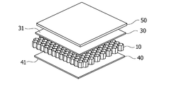
- 1 is an exploded perspective view showing an embodiment of a vehicle interior material according to the present invention.
- FIG. 5 is a schematic cross-sectional view of an embodiment of the vehicle interior material shown in FIG. 4.
- A) is a schematic diagram which shows the position of a bending neutral axis at the time of bending the structure provided with the core layer and the film layer of the both surfaces in the vehicle interior material which concerns on this invention
- (b) is this structure.
- FIG. 1 is a perspective view showing a manufacturing process of a core material to be the core layer.
- the core material is described in detail in WO 2006/053407, which is incorporated herein by reference.
- this core material 1 is formed by thermoforming a flat sheet of material with a roller (not shown) having a predetermined mold, and plastically deforming the sheet substantially without cutting it. ..
- the material of the core material 1 is not limited to these, but for example, a thermoplastic resin such as polypropylene (PP), polyethylene (PE), or polyethylene terephthalate (PET), a composite material with fibers, paper, metal, or the like is used.
- a thermoplastic resin is preferable. In this embodiment, the case where a thermoplastic resin is used will be described.
- the thickness of the material sheet is not limited to this, but is preferably in the range of 0.05 mm to 0.50 mm, and the thickness of the core material 1 after thermoforming is substantially the same.
- the core material 1 has a three-dimensional structure in which peak portions 11 and valley portions 12 are alternately arranged in the width direction X orthogonal to the manufacturing direction Y.
- the ridge portion 11 is composed of two side surfaces 13 and a top surface 17 between them, and the valley portion 12 is composed of two side surfaces 13 shared by the adjacent ridge portions 11 and a bottom surface 14 therebetween.
- the shape of the mountain portion 11 is a trapezoid as shown in FIG. 1 will be described, but the present invention is not limited to this, and in addition to polygons such as triangles and rectangles, sinusoidal curves and A curved shape such as an bow shape may be used.
- the core material 1 is provided with the above three-dimensional structure so as to be continuous in the manufacturing direction Y. That is, as shown in FIG. 1, a plurality of peaks 11a, 11b, 11c, 11d are continuously formed in the manufacturing direction Y.
- the valleys 12 are similarly formed continuously.
- the connection between the peaks 11 and the connection between the valleys 12 are made by alternately repeating two types of connection methods.
- the first connection method is such that, on the first folding line X1 in the width direction, the top surfaces 17b and 17c of two adjacent ridges 11b and 11c are trapezoidal ridge connection surfaces.
- the connection is made via 15b and 15c.
- the mountain connecting surface 15 is formed at an angle perpendicular to the top surface 17.
- the bottom surfaces 14b and 14c of two adjacent valley portions are directly connected.
- the bottom surfaces 14a and 14b (or 14c and 14d) of two adjacent valley portions are trapezoidal valley portions on the second folding line X2 in the width direction.
- the connection is made via the connection surfaces 16a, 16b (or 16c, 16d).
- the valley connecting surface 16 is formed at a right angle with respect to the bottom surface 14.
- the top surfaces 12a and 12b (or 12c and 12d) of two adjacent mountain portions are directly connected.
- the core material 1 a plurality of three-dimensional structures (peak portion 11, valley portion 12) are connected via the connection region (peak portion connecting surface 15, valley connecting surface 16), and the connecting region is folded.
- the core layer of the vehicle interior material of the present invention is formed.
- the first folding line X1 is a mountain fold, and the bottom surfaces 14b and 14c of two adjacent valley portions are overlapped with each other via their back surfaces, and the mountain portion connecting surface 15b of two adjacent mountain portions, Fold it so that the angle formed by 15c opens up to 180 degrees.
- the second folding line X2 is a valley fold, and the top surfaces 17a and 17b (or 17c and 17d) of two adjacent peak portions overlap each other, and the valley connection surfaces 16a and 16b (of the two adjacent valley portions). Or, it is folded so that the angle formed by 16c and 16d) is closed up to 180 degrees.
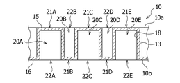
- the core layer 10 of the vehicle interior material of the present invention obtained by folding the core material 1 in this manner is shown in FIGS. 2 and 3.
- the core layer 10 is provided with cells 20 each having a substantially hexagonal tubular shape and arranged in a plurality of rows, and cells formed by two adjacent crests in every other row. 20A, 20C, 20E and cells 20B, 20D formed from two adjacent valleys are arranged.
- the broken line 18 in FIG. 3 is the surface that was the back surface of the core material, and generally indicates the inner wall of the cell 20 having a substantially hexagonal tubular shape.
- Each of the cells 20A, 20C, and 20E formed from the mountain portion has six cell side walls forming a substantially hexagonal tubular shape, and these cell side walls are formed by two top surfaces 17 and four side surfaces 13 of the cell material. It is a thing. Further, these cells 20A, 20C, 20E are substantially hexagonal cylindrical closed surfaces 21A that close the cell ends at the cell ends of one surface 10a of the core layer 10 (the surface on the front side in FIG. 2), 21C, 21E, the one closing surface 21 of which is formed by two trapezoidal ridge connecting surfaces 15 in the cell material, respectively.
- these cells 20A, 20C, 20E are provided with open ends 22A, 22C, 22E that are opened in a substantially hexagonal shape at the cell ends of the other surface 10b opposite to the core layer 10.
- the open ends 22A, 22C, and 22E allow the internal spaces of the cells 20A, 20C, and 20E to communicate with the outside.
- Each of the cells 20B and 20D formed from the valley portion also has six cell side walls forming a substantially hexagonal tubular shape, and these cell side walls are formed by two bottom surfaces 14 and four side surfaces 13 of the cell material. is there. Further, these cells 20B and 20D are provided with open ends 22B and 22D that are opened in a substantially hexagonal shape at the cell ends of the one surface 10a of the core layer 10. The open ends 22B and 22D allow the internal spaces of the cells 20B and 20D to communicate with the outside. Further, these cells 20B, 20D are provided with substantially hexagonal cylindrical closing surfaces 21B, 21D for closing the cell ends at the cell ends of the other surface 10b opposite to the core layer 10, respectively. The closing surface 21 of is formed by two trapezoidal valley connecting surfaces 16 of cell material.
- the core layer 10 has the one side closed surfaces 21A, 21C, and 21E formed by the crests of the cell material in every other row at the cell ends of the one surface 10a, and on the other surface 10b.
- the cell end has the other side closing surfaces 21B, 21D formed from the valleys in the cell material in a row of cells different from the above, but unless otherwise specified, one side closing surface, Both of the closing surfaces 21 on the other side have substantially the same function.
- the total thickness of the core layer 10 is not limited to the following because it varies depending on which part of the automobile the interior material for a vehicle is used for.
- the range is preferable, and the range of 5 mm to 20 mm is more preferable.
- Basis weight of the core layer 10 (weight per unit area), because the change in or used vehicle interior material where the parts of the automobile, but not limited to, a range of 400 g / m 2 from 4000 g / m 2 The range of 500 g/m 2 to 3000 g/m 2 is more preferable.
- the basis weight of the core layer 10 includes the type of material of the core layer 10, the thickness of the entire core layer 10, the wall thickness of the cells 20 (the thickness of the material sheet), and the pitches Pcx and Pcy between the cells 20 of the core layer 10. It can also be adjusted by (distance between center axes of cells).
- the pitch Pcy between the cells 20 in the direction in which the cells 20 are adjacent to each other in a row in the core manufacturing direction Y is set to a range of 2 mm to 20 mm. It is preferable and it is more preferable to set it in the range of 3 mm to 15 mm.
- the vehicle interior material of the first embodiment includes the core layer 10 described above, the design layer 50 provided on one surface of the core layer 10, the core layer 10 and the design layer 50. And a second film layer 40 provided on the other surface of the core layer 10.
- the interior material for a vehicle of the present invention is used so that the design layer 50 side is located inside the vehicle interior.
- the structure 60 of the first film layer 30, the core layer 10 and the second film layer 40 is the first
- the strain ⁇ a of the surface 31 on the film layer side is smaller than the strain ⁇ b of the surface 41 on the second film layer side. Since the vehicle interior material has such a relationship between the strain ⁇ a and the strain ⁇ b, when the vehicle interior material is molded into a predetermined uneven shape, the vehicle interior material bends as shown in FIG. 6(a).
- the bending center axis NA of the structure 60 moves in the direction of the surface 31 on the first film layer side from the center position of the thickness of the structure 60, and thus the first design layer 50 side
- the amount of deformation of the surface 41 on the second film layer side opposite to the design layer 50 is larger than the amount of deformation of the surface 31 on the film layer side. Therefore, when the interior layer material for a vehicle is bent and the design layer 50 contracts, the amount of the contracting deformation can be reduced, and thus the design layer 50 cannot be completely contracted and wrinkles have occurred. It is possible to suppress the generation of wrinkles.
- the first film layer 30 and the second film layer 30 This can be performed by making a difference in tensile compression rigidity of the film layer 40.
- a difference in tensile compression rigidity for example, even if the same resin film material is used for the first and second film layers 30 and 40, it is necessary to disperse inorganic particles such as talc in the first film layer 30.
- the tensile compression rigidity of the first film layer 30 can be increased.
- the core layer 10 is not limited to the core layer having the specific structure shown in FIGS. 1 to 3 described above, but may be any core layer in which a general tubular cell is arranged in a plurality of rows.
- the design layer 50 can be formed by setting the relationship with h so that 0 ⁇ a ⁇ h/( ⁇ a+ ⁇ b) ⁇ 5. It is possible to suppress wrinkles from being generated.
- the thickness h of the structure is the total of the thickness of the core layer 10 described above and the thicknesses of the first and second film layers 30 and 40 described later in detail, and for example, the lower limit thereof is preferably 3 mm or more, and 4 mm or more. Is preferable, and 5 mm or more is more preferable. Further, the upper limit is preferably 20 mm or less, more preferably 15 mm or less, and further preferably 10 mm or less.
- the materials of the first and second film layers 30 and 40 are not limited to these, but include, for example, resin films such as polypropylene (PP), polyethylene (PE), polyethylene terephthalate (PET), and polyamide (PA), An olefin-based or urethane-based elastomer film can be used.
- resin films such as polypropylene (PP), polyethylene (PE), polyethylene terephthalate (PET), and polyamide (PA)
- An olefin-based or urethane-based elastomer film can be used.
- the same material may be used for the first film layer 30 and the second film layer 40, or different materials may be used for the relationship between the strain ⁇ a and the strain ⁇ b, or the strain ⁇ a and the strain ⁇ b and the structure.
- the thickness h may be satisfied.
- the tension and compression of the first and second film layers 30 and 40 are performed.
- the rigidity can be increased, and thereby the above-described relationship between the strain ⁇ a and the strain ⁇ b or the above-described relationship between the strain ⁇ a and the strain ⁇ b and the thickness h of the structure may be satisfied.
- the size of the inorganic particles is not particularly limited, but for example, the average particle size is preferably 0.05 to 2 ⁇ m, more preferably 0.1 to 1 ⁇ m.
- the “average particle size” refers to a particle size of 50% in total from the particle side in the volume-based particle size distribution measured by the laser diffraction/scattering method.
- the first and second film layers 30 and 40 can be obtained. It is possible to reduce the tensile compression rigidity of the above, and thereby the above relationship between the strain ⁇ a and the strain ⁇ b or the above relationship between the strain ⁇ a and the strain ⁇ b and the thickness h of the structure may be satisfied.
- the size of the rubber particles is not particularly limited, but for example, those having an average particle diameter of 1 to 100 ⁇ m are preferable, and those of 20 to 70 ⁇ m are more preferable.
- the thickness of the first and second film layers 30 and 40 is not particularly limited, but for example, the lower limit thereof is preferably 0.03 mm or more, more preferably 0.04 mm or more, and further preferably 0.05 mm or more.
- the upper limit of the thickness is preferably 0.5 mm or less, more preferably 0.4 mm or less, and further preferably 0.3 mm or less.
- the first film layer 30 and the second film layer 40 may have the same thickness, or may have different thicknesses, or the relationship between the strain ⁇ a and the strain ⁇ b, or the strain ⁇ a and the strain ⁇ b and the thickness of the structure. You may make it satisfy
- a metal foil such as an aluminum foil, a stainless steel foil, or a copper foil is laminated between the first film layer 30 and the design layer 50 or between the first film layer 30 and the core layer 10.
- the thickness h may be satisfied.
- the thickness of the metal foil is preferably thin in order to reduce the weight of the vehicle interior material.
- the upper limit thereof is preferably 0.2 mm or less, more preferably 0.1 mm or less.
- the lower limit of the thickness is not particularly limited, but 0.005 mm or more is preferable, and 0.01 mm or more is more preferable.
- the first and second film layers 30 and 40 may be heat-welded and adhered to the core layer 10, or may be adhered via an adhesive (not shown).
- the adhesive is not particularly limited, but for example, an epoxy-based or acrylic-based adhesive can be used.
- each of the first and second film layers 30 and 40 may have a three-layer structure and include a central layer and two adhesive layers located on both sides of the central layer.
- a material having a melting point lower than that of the material used for the central layer is used as the material of the adhesive layer. For example, by using a polyamide having a melting point of 190 to 220° C. for the central layer and a polyethylene having a melting point of 90 to 130° C.
- the first and second film layers 30 and 40 are When the temperature at the time of bonding to the layer 10 and the temperature for thermoforming into a predetermined shape of the vehicle interior material are set to about 150°C to 160°C, the central layer does not melt but only the adhesive layer melts. Then, the core layer 10 can be firmly bonded.
- a resin having a melting point higher than that of polyethylene for the adhesive layer polypropylene is used in addition to polyamide.
- the design layer 50 may be one that is used as a design layer of an ordinary vehicle interior material, and is not particularly limited, but for example, a non-woven fabric, a plain needle, a layer composed of fibers such as velor, It may be a layer composed of foamed urethane, foamed resin such as foamed polyethylene or foamed nylon, or a layer in which these are combined.
- the non-woven fabric is not limited to these, but it is preferable to use various non-woven fabrics such as spunbond, spunlace, or needle punch using a resin such as polyethylene terephthalate (PET), polypropylene (PP), or polyethylene (PE).
- the basis weight of the design layer 50 is not limited to the following because it changes depending on which part of the automobile the vehicle interior material is used for.
- the lower limit thereof is preferably 10 g/m 2 or more, and 20 g/m 2 or more. More preferably, 30 g/m 2 or more is still more preferable.
- the upper limit of the basis weight for example, preferably 500 g / m 2 or less, more preferably 300 g / m 2 or less, 250 g / m 2 or less is more preferable.
- the interior material for a vehicle of the second embodiment has the above-described core layer 10, a design layer 50 provided on one surface thereof, and a space between the core layer 10 and the design layer 50. And a second film layer 40a having a plurality of apertures provided on the other surface of the core layer 10.
- the same components as those in the first embodiment are designated by the same reference numerals, and detailed description thereof will be omitted here.
- the openings in the second film layer 40a penetrate the layer, so the second film layer 40a is breathable.
- the strain ⁇ a of the surface 31 on the first film layer side is calculated as follows. It can be made smaller than the strain ⁇ b of the surface 41.
- the relationship between the strain ⁇ a of the surface 31 on the first film layer side of the structure 60, the strain ⁇ b of the surface 41 on the second film layer side, and the thickness h of the structure 60 is 0 ⁇ a ⁇ h. It is possible to satisfy the equation of /( ⁇ a+ ⁇ b) ⁇ 5.
- the opening is performed before the second film layer 40a is bonded to the core layer 10, and is opened by, for example, a hot needle or punching (punching using a male die and a female die) to form a hole.
- the holes In order to prevent the holes from being blocked, it is preferable that the holes have a hole shape that minimizes burr.
- the aperture pattern is not particularly limited, but it is preferable to arrange in a staggered arrangement or a lattice arrangement.
- the porosity of the second film layer 40a is not particularly limited, but is preferably in the range of 0.2% to 5%.
- the diameter of the aperture is preferably in the range of 0.25 mm to 2.5 mm, more preferably in the range of 0.3 mm to 2.0 mm.
- the pitch of the openings of the second film layer 40a does not necessarily have to match the pitches Pcx and Pcy of the cells 20 of the core layer 10 shown in FIG. It is not always necessary to align the openings with the cells 20 when they are attached to the layer 10. This is because the openings of the second film layer 40a and the positions of the open ends 22 of the cells 20 of the core layer 10 randomly overlap with each other, so that the communication between the inside and the outside can be appropriately secured.
- the pitch of the openings of the second film layer 40a is preferably smaller than the pitch of the cells 20 of the core layer 10 in at least either the X direction or the Y direction.
- the tensile compression rigidity of the second film layer 40a can be lowered, and the same as in the first embodiment.
- a plurality of openings is provided only in the second film layer 40a, but the present invention is not limited to this, and a plurality of openings is provided in both the first and second film layers 30 and 40.
- the holes may be provided, or a plurality of holes may be provided only in the first film layer 30, and means other than the openings (film material, addition of inorganic or rubber particles, or metal foil).
- the relationship between the strain ⁇ a and the strain ⁇ b, or the relationship between the strain ⁇ a and the strain ⁇ b and the thickness h of the structure may be satisfied by, for example, stacking.
- the core layer 10 having a structure in which tubular cells are arranged in a plurality of rows is used as the core layer of the vehicle interior material.
- the present invention is not limited to this, and if the core layer 10 has a hard structure having a hollow portion inside, it is heat-formed into a predetermined uneven shape while maintaining weight reduction and high rigidity. Also, it is possible to prevent wrinkles from being generated on the design surface.
- the hard core layer may have a Young's modulus of 100 kPa or more in the compression direction (that is, the direction between the two surfaces on which the first and second film layers 30 and 40 are attached), and the material of the core layer is In addition to the material of the core material, for example, a fiber material or a urethane material may be used.
- a vehicle interior material including the core layer, the first and second film layers, and the design layer shown in FIG. 7 was produced.
- the core layer material: polypropylene (PP) resin, cell pitch Pcy: 4 mm, core layer thickness: 6 mm
- the first film layer Material: Polypropylene (PP) film, thickness: 70 ⁇ m
- the second film layer material: polypropylene (PP) film with a three-layer structure, thickness: 65 ⁇ m, openings) Pitch: 7 mm
- this structure was subjected to three-point bending using a universal material testing machine (manufactured by Instron, model 5900) to measure strain.
- the test piece of the structure had a size of 60 mm ⁇ 200 mm.
- the test piece 60S of the structure was supported by two fulcrums 82 positioned at 100 mm intervals, and a load of 0.5 mm was applied to the center position of the fulcrum by an indenter 84.
- a strain measuring instrument PCD-400A manufactured by Kyowa Denki Co., Ltd.
- the strain ⁇ a on the surface on the first film layer side was 396 ⁇
- the strain ⁇ b on the surface on the second film layer side was 408 ⁇ .
- a design layer material: plain needle, thickness: 1 mm
- this vehicle interior material was heat-molded into a U shape, and the surface of the design layer of the vehicle interior material after the heat molding was visually observed. As a result, no wrinkles were observed on the surface of the design layer of the vehicle interior material.
- Test Examples 2 to 5 as shown in Table 1, except that the thickness of the film layer and the core layer was changed or a metal foil was provided on the film layer, it was prepared in the same manner as in Test Example 1, The strain was measured and the surface of the design layer after heat molding was observed. The results are shown in Table 1.
- Test Example 6 which was prepared in the same manner as Test Example 1 except that the second film layer had the same structure as the first film layer, was strained in the same manner as in Test Example 1. And the surface of the design layer after heat molding was observed. The results are shown in Table 1.
- the vehicle interior material of the present invention while maintaining high rigidity, it is possible to suppress the occurrence of wrinkles on the surface of the design layer after heat molding, the vehicle interior material of the present invention, Are useful for parts that require high rigidity and aesthetics, such as floor carpets, trunk trims, trunk floors, headlinings, and seat back covers.
Abstract
Provided is a vehicle internal material in which wrinkles can be prevented from forming in a design surface even if the material is heat-molded to a prescribed uneven shape, while reduced weight and a high degree of stiffness are maintained. This vehicle interior material is a multilayered structure comprising a hard core layer having a hollow part in the interior, a design layer provided to one surface-side of the core layer, a first film layer provided between the core layer and the design layer, and a second film layer provided to the surface of the core layer on the side opposite the first film layer. Strain εa in a first-film-layer-side surface 31 in a structural body 60 of the first film layer, the core layer, and the second film layer is less than strain εb in a second-film-layer-side surface 42 of the structural body.
Description
本発明は、車両用内装材に関する。
The present invention relates to a vehicle interior material.
自動車の構造として、前方にエンジン室があり、後方にはトランク室があり、その中間に客室を設ける構造が一般的である。客室には、運転席、助手席および後部座席といった座席を設けている。また、客室には、自動車内装の外側を覆うようにダッシュインシュレータ、フロアーカーペット、フロアースペーサ、トランクトリム、及びトランクフロアーが設置されており、これら部品は、車体の形状や部品のデザインに合わせた凹凸状の形状に成形されている。更に、車体下の外装には、フロントフェンダーライナー、リアフェンダーライナー、及び空気の流れを制御する凹凸形状に成形されたアンダーカバーが設置されている。これら部品の多くは、材料として熱可塑性樹脂が使用され、この材料を加熱して当該部品の形状の型によりプレス成形し、厚みが異なる複数の部分を有する凹凸形状の部品に仕上げられる。
In general, the structure of an automobile has an engine room in the front, a trunk room in the rear, and a passenger compartment in the middle. The passenger compartment has seats such as driver's seat, passenger seat and rear seat. In addition, dash insulators, floor carpets, floor spacers, trunk trims, and trunk floors are installed in the cabin so as to cover the outside of the automobile interior.These parts are uneven according to the shape of the vehicle body and the design of the parts. It is molded into the shape of a circle. Further, a front fender liner, a rear fender liner, and an undercover formed in a concavo-convex shape for controlling the flow of air are installed on the exterior under the vehicle body. In many of these parts, a thermoplastic resin is used as a material, and the material is heated and press-molded by a mold having the shape of the part to finish into an uneven part having a plurality of parts having different thicknesses.
これら自動車の部品は、高い剛性が求められると同時に、燃費削減のために軽量化も求められている。更に、これら自動車の部品のうち、自動車のユーザーから見える内装材は、意匠性が重要視されるため、部品の表面に意匠層として、不織布や、プレーンニードル、ベロア等の繊維で構成された層が貼られている。また、自動車開発の最近の動向として車内の静寂性が重要視されている。自動車の車内に伝わる騒音としては、ウインドウからの騒音、タイヤからの騒音、車体下からの騒音、エンジン音からの騒音、モータ音からの騒音などがある。よって、上述した自動車の部品に、自動車で発生する騒音に対する音響性能も求められている。
These parts for automobiles are required to have high rigidity, and at the same time, to be lightweight in order to reduce fuel consumption. Further, among these automobile parts, the interior material that can be seen by the user of the automobile is important in terms of design. Therefore, as a design layer on the surface of the component, a non-woven fabric, a layer composed of fibers such as plain needles and velours. Is affixed. In addition, as a recent trend of automobile development, quietness inside the vehicle is emphasized. Noise transmitted to the interior of a vehicle includes noise from windows, noise from tires, noise from under the vehicle, noise from engine sounds, noise from motor sounds, and the like. Therefore, the above-mentioned automobile parts are also required to have acoustic performance against noise generated in the automobile.
高剛性と軽量化を同時に達成するために、ハニカムコアなどの筒状のセルが複数の列をなして配置されている中空コア材がよく利用されている。例えば、特許文献1には、熱可塑性樹脂製の中空板状体の少なくとも一方の主面に、繊維シートと熱可塑性樹脂フィルムとを順に貼り合せた積層構造体が記載されている。そして、この積層構造体は、軽量化を図れるとともに、折り曲げても折り曲げ部分に座屈による突出シワや凹部は発生しにくいことが記載されている。
In order to achieve both high rigidity and light weight at the same time, hollow core materials in which tubular cells such as honeycomb cores are arranged in multiple rows are often used. For example, Patent Document 1 describes a laminated structure in which a fiber sheet and a thermoplastic resin film are sequentially laminated on at least one main surface of a thermoplastic resin hollow plate-shaped body. Further, it is described that this laminated structure can be made lightweight, and that even when it is bent, protruding wrinkles and recesses due to buckling do not easily occur at the bent portion.
車両用内装材は、高剛性と軽量化が求められるとともに、自動車のユーザーから見える場所に配置されるため、意匠性も重要視される。よって、車両用内装材の表面には、意匠層として、一般に、不織布や、プレーンニードル、ベロア等の繊維で構成された層が貼られている。しかしながら、高剛性と軽量化を達成するために、筒状のセルが複数の列をなして配置されているコア材に意匠層を単に貼ると、所定の凹凸形状に加熱成形した後に、意匠層に皺が発生してしまうという問題がある。
▽Vehicle interior materials are required to have high rigidity and light weight, and because they are placed in a place visible to automobile users, design is also important. Therefore, on the surface of the vehicle interior material, as a design layer, a layer made of non-woven fabric, fibers such as plain needles and velours is generally attached. However, in order to achieve high rigidity and weight reduction, when the design layer is simply pasted on the core material in which the tubular cells are arranged in a plurality of rows, the design layer is formed after heat molding into a predetermined uneven shape. There is a problem that wrinkles occur in the.
そこで本発明は、軽量化および高い剛性を維持しつつ、所定の凹凸形状に加熱成形しても、意匠面に皺が発生することを防ぐことができる車両用内装材を提供することを目的とする。
Therefore, an object of the present invention is to provide an interior material for a vehicle that can prevent wrinkles from being generated on a design surface even when heat-molded into a predetermined uneven shape while maintaining weight reduction and high rigidity. To do.
上記の目的を達成するために、本発明は、内部に中空部を有する硬質なコア層と、前記コア層の一方の面側に設けられた意匠層と、前記コア層と前記意匠層との間に設けられた第1のフィルム層と、前記コア層の前記第1のフィルム層とは反対側の面に設けられた第2のフィルム層とを備える複層構造の車両用内装材であって、前記第1のフィルム層、前記コア層、および前記第2のフィルム層の構造体における前記第1のフィルム層側の面のひずみεaは、前記構造体の前記第2のフィルム層側の面のひずみεbよりも小さい。
In order to achieve the above object, the present invention, a hard core layer having a hollow portion inside, a design layer provided on one surface side of the core layer, the core layer and the design layer A vehicle interior material having a multi-layer structure, comprising a first film layer provided between the core layer and a second film layer provided on a surface of the core layer opposite to the first film layer. Then, the strain εa of the surface on the side of the first film layer in the structure of the first film layer, the core layer, and the second film layer is equal to that of the structure on the side of the second film layer of the structure. It is smaller than the surface strain εb.
前記硬質なコア層は、圧縮方向のヤング率が100kPa以上であってよい。前記コア層は、筒状のセルが複数の列をなして配置された構造を有していてもよい。前記筒状のセルは、略四角筒状や略六角筒状などの多角筒状であってもよいし、略円筒状や略楕円筒状などの曲線筒状であってもよい。前記コア層の前記セルの各々は、一方の端に閉鎖面、他方の端に開放端を有し、前記セルの前記解放端によって前記セルの内部空間が外部と連通しており、前記セルの前記解放端は、前記コア層の両面において、隣接したセルの列が一列おきに配置されていることが好ましい。前記解放端、前記一方側閉鎖面、および前記他方側閉鎖面は、前記セルの形状に従い、略四角形状や略六角形状などの多角形状であっても、略円形状や略楕円形状などの曲線形状であってもよい。
The Young's modulus in the compression direction of the hard core layer may be 100 kPa or more. The core layer may have a structure in which tubular cells are arranged in a plurality of rows. The tubular cell may have a polygonal tubular shape such as a substantially square tubular shape or a substantially hexagonal tubular shape, or may have a curved tubular shape such as a substantially cylindrical shape or an approximately elliptic cylindrical shape. Each of the cells of the core layer has a closed surface at one end and an open end at the other end, the internal space of the cell communicating with the outside by the open end of the cell, It is preferable that the open ends are arranged such that rows of adjacent cells are arranged every other row on both surfaces of the core layer. According to the shape of the cell, the open end, the one-sided closing surface, and the other-sided closing surface are polygonal shapes such as a substantially quadrangular shape and a hexagonal shape, but are also curves such as a substantially circular shape and a substantially elliptical shape. It may have a shape.
前記構造体における前記第1のフィルム層側の面のひずみεaと、前記構造体の前記第2のフィルム層側の面のひずみεbと、前記構造体の厚みhとの関係は、0<εa×h/(εa+εb)<5の式を満たすことが好ましい。前記第1のフィルム層または前記第2のフィルム層は、層を貫通する複数の開孔を有していてもよい。前記構造体の厚みhは、20mm未満であることが好ましい。
The relationship between the strain εa of the surface of the structure on the first film layer side, the strain εb of the surface of the structure on the second film layer side, and the thickness h of the structure is 0<εa. It is preferable that the formula xh/(εa+εb)<5 is satisfied. The first film layer or the second film layer may have a plurality of apertures penetrating the layer. The thickness h of the structure is preferably less than 20 mm.
内部に中空部を有する硬質なコア層を備える複層構造体を曲げると、曲げによって縮む側の表面では、曲げる量が大きい場合、縮みきれなかった材料が複層構造体の外側に逃げるため、皺が発生してしまう。本発明に係る車両用内装材は、第1のフィルム層とコア層と第2のフィルム層との構造体において、意匠層側の第1のフィルム層側の面のひずみεaを、構造体の第2のフィルム層側の面のひずみεbよりも小さくしたことから、車両用内装材を曲げた際に、意匠層側の第1のフィルム層側の面が縮む変形量よりも、その反対側の第2のフィルム層側の面が伸びる変形量が大きくなることから、意匠層50に皺が発生することを抑制することができる。よって、軽量化および高い剛性を維持しつつ、所定の凹凸形状に加熱成形しても、意匠面に皺が発生することを防ぐことができる。
When a multilayer structure including a hard core layer having a hollow portion inside is bent, on the surface on the side contracted by bending, if the amount of bending is large, the material that could not be shrunk escapes to the outside of the multilayer structure, Wrinkles will occur. The vehicle interior material according to the present invention, in the structure of the first film layer, the core layer and the second film layer, the strain εa of the surface on the side of the first film layer on the design layer side, Since the strain εb on the surface on the side of the second film layer is smaller than that on the side opposite to the deformation amount of the surface on the side of the first film layer on the design layer side when the vehicle interior material is bent. Since the amount of deformation in which the surface of the second film layer side extends is large, it is possible to suppress wrinkles from occurring in the design layer 50. Therefore, it is possible to prevent wrinkles from being generated on the design surface even when heat-molded into a predetermined uneven shape while maintaining weight reduction and high rigidity.
また、コア層として、筒状のセルが複数の列をなして配置されたコア層とすることで、軽量化を維持しつつ、より高い剛性を発揮させることができる。特に、コア層のセルの各々が、一方の端に閉鎖面、他方の端に開放端を有し、セルの解放端によってセルの内部空間が外部と連通しており、セルの解放端は、コア層の両面において、隣接したセルの列が一列おきに配置されている構成にすることで、高い剛性を維持しつつ、更なる軽量化および第1及び第2のフィルム層との接着性を向上させることができる。
Also, as the core layer is a core layer in which tubular cells are arranged in a plurality of rows, it is possible to achieve higher rigidity while maintaining weight reduction. In particular, each of the cells of the core layer has a closed surface at one end and an open end at the other end, and the open end of the cell communicates the internal space of the cell with the outside, and the open end of the cell is Adjacent rows of cells are arranged every other row on both sides of the core layer to maintain high rigidity and further reduce weight and improve adhesiveness with the first and second film layers. Can be improved.
以下、添付の図面を参照して、本発明に係る車両用内装材の一実施の形態について説明する。なお、図面は、別段の定めがない限り、縮尺通りに描くことを意図してはいない。
Hereinafter, an embodiment of a vehicle interior material according to the present invention will be described with reference to the accompanying drawings. It should be noted that the drawings are not intended to be drawn to scale unless otherwise specified.
先ず、本発明に係る車両用内装材の各実施の形態において共通するコア層について説明する。図1は、このコア層となるコア材料の製造過程を示す斜視図である。なお、このコア材料は、ここに引用することで本明細書の記載の一部をなすものとする国際公開第2006/053407号にその製造方法が詳細に記載されている。
First, a core layer common to each embodiment of the vehicle interior material according to the present invention will be described. FIG. 1 is a perspective view showing a manufacturing process of a core material to be the core layer. The core material is described in detail in WO 2006/053407, which is incorporated herein by reference.
図1に示すように、このコア材料1は、平坦な材料シートを所定の型を有するローラ(図示省略)によって熱成形され、実質的にシートを切ることなく塑性変形により形成されたものである。コア材料1の素材は、これらに限定されないが、例えば、ポリプロピレン(PP)、ポリエチレン(PE)、ポリエチレンテレフタラート(PET)などの熱可塑性樹脂や、繊維との複合材料、紙、金属等を用いることができ、特に熱可塑性樹脂が好ましい。本実施の形態では、熱可塑性樹脂を用いた場合について説明する。材料シートの厚みは、これに限定されないが、例えば、0.05mmから0.50mmの範囲が好ましく、熱成形後のコア材料1の厚みもほぼ同様である。
As shown in FIG. 1, this core material 1 is formed by thermoforming a flat sheet of material with a roller (not shown) having a predetermined mold, and plastically deforming the sheet substantially without cutting it. .. The material of the core material 1 is not limited to these, but for example, a thermoplastic resin such as polypropylene (PP), polyethylene (PE), or polyethylene terephthalate (PET), a composite material with fibers, paper, metal, or the like is used. In particular, a thermoplastic resin is preferable. In this embodiment, the case where a thermoplastic resin is used will be described. The thickness of the material sheet is not limited to this, but is preferably in the range of 0.05 mm to 0.50 mm, and the thickness of the core material 1 after thermoforming is substantially the same.
コア材料1は、製造方向Yに対して直交する幅方向Xに向かって、山部11と谷部12が交互に配置される三次元構造を有している。山部11は、2つの側面13とその間の頂面17とで構成され、谷部12は、隣接する山部11と共有する2つの側面13とその間の底面14とで構成される。なお、本実施の形態では、図1に示すように山部11の形状が台形の場合について説明するが、本発明はこれに限定されず、三角形や長方形などの多角形の他、正弦曲線や弓形などの曲線形にしてもよい。
The core material 1 has a three-dimensional structure in which peak portions 11 and valley portions 12 are alternately arranged in the width direction X orthogonal to the manufacturing direction Y. The ridge portion 11 is composed of two side surfaces 13 and a top surface 17 between them, and the valley portion 12 is composed of two side surfaces 13 shared by the adjacent ridge portions 11 and a bottom surface 14 therebetween. In the present embodiment, the case where the shape of the mountain portion 11 is a trapezoid as shown in FIG. 1 will be described, but the present invention is not limited to this, and in addition to polygons such as triangles and rectangles, sinusoidal curves and A curved shape such as an bow shape may be used.
コア材料1は、上記の三次元構造を、製造方向Yに向かって連続するように備える。すなわち、図1に示すように、製造方向Yに向かって複数の山部11a、11b、11c、11dが連続して形成される。谷部12も同様に連続して形成される。そして、山部11間の接続および谷部12間の接続は、2種類の接続方法を交互に繰り返すことでなされている。
The core material 1 is provided with the above three-dimensional structure so as to be continuous in the manufacturing direction Y. That is, as shown in FIG. 1, a plurality of peaks 11a, 11b, 11c, 11d are continuously formed in the manufacturing direction Y. The valleys 12 are similarly formed continuously. The connection between the peaks 11 and the connection between the valleys 12 are made by alternately repeating two types of connection methods.
第1の接続方法は、図1に示すように、幅方向の第1の折り畳み線X1において、隣接する2つの山部11b、11cの頂面17b、17cが、それぞれ台形状の山部接続面15b、15cを介して接続するというものである。山部接続面15は頂面17に対して直角の角度で形成されている。この幅方向の第1の折り畳み線X1において、隣接する2つの谷部の底面14b、14cは、直接に接続している。第2の接続方法は、図1に示すように、幅方向の第2の折り畳み線X2において、隣接する2つの谷部の底面14a、14b(又は14c、14d)が、それぞれ台形状の谷部接続面16a、16b(又は16c、16d)を介して接続するというものである。谷部接続面16は底面14に対して直角の角度で形成されている。この幅方向の第2の折り畳み線X2において、隣接する2つの山部の頂面12a、12b(又は12c、12d)は、直接に接続している。
As shown in FIG. 1, the first connection method is such that, on the first folding line X1 in the width direction, the top surfaces 17b and 17c of two adjacent ridges 11b and 11c are trapezoidal ridge connection surfaces. The connection is made via 15b and 15c. The mountain connecting surface 15 is formed at an angle perpendicular to the top surface 17. On the first folding line X1 in the width direction, the bottom surfaces 14b and 14c of two adjacent valley portions are directly connected. In the second connection method, as shown in FIG. 1, the bottom surfaces 14a and 14b (or 14c and 14d) of two adjacent valley portions are trapezoidal valley portions on the second folding line X2 in the width direction. The connection is made via the connection surfaces 16a, 16b (or 16c, 16d). The valley connecting surface 16 is formed at a right angle with respect to the bottom surface 14. On the second folding line X2 in the width direction, the top surfaces 12a and 12b (or 12c and 12d) of two adjacent mountain portions are directly connected.
このようにコア材料1は、複数の三次元構造(山部11、谷部12)が接続領域(山部接続面15、谷部接続面16)を介して接続されており、接続領域を折り畳むことで、本発明の車両用内装材のコア層が形成される。具体的には、第1の折り畳み線X1では山折りで、隣接する2つの谷部の底面14b、14c同士が、その裏面を介して重なり合い、隣接する2つの山部の山部接続面15b、15cのなす角度が180度まで開くように折り畳む。また、第2の折り畳み線X2では谷折りで、隣接する2つの山部の頂面17a、17b(又は17c、17d)同士が重なり合い、隣接する2つの谷部の谷部接続面16a、16b(又は16c、16d)のなす角度が180度まで閉じるように折り畳む。このようにコア材料1を折り畳むことで得られた本発明の車両用内装材のコア層10を、図2及び図3に示す。
As described above, in the core material 1, a plurality of three-dimensional structures (peak portion 11, valley portion 12) are connected via the connection region (peak portion connecting surface 15, valley connecting surface 16), and the connecting region is folded. As a result, the core layer of the vehicle interior material of the present invention is formed. Specifically, the first folding line X1 is a mountain fold, and the bottom surfaces 14b and 14c of two adjacent valley portions are overlapped with each other via their back surfaces, and the mountain portion connecting surface 15b of two adjacent mountain portions, Fold it so that the angle formed by 15c opens up to 180 degrees. Further, the second folding line X2 is a valley fold, and the top surfaces 17a and 17b (or 17c and 17d) of two adjacent peak portions overlap each other, and the valley connection surfaces 16a and 16b (of the two adjacent valley portions). Or, it is folded so that the angle formed by 16c and 16d) is closed up to 180 degrees. The core layer 10 of the vehicle interior material of the present invention obtained by folding the core material 1 in this manner is shown in FIGS. 2 and 3.
図2及び図3に示すように、コア層10は、複数の列をなして配置されている略六角筒状のセル20を備え、一列おきに、隣接する2つの山部から形成されたセル20A、20C、20Eと、隣接する2つの谷部から形成されたセル20B、20Dが配置される。図3中の破線18は、コア材料の裏面であった面であり、略六角筒状のセル20の内壁を概ね示すものである。
As shown in FIGS. 2 and 3, the core layer 10 is provided with cells 20 each having a substantially hexagonal tubular shape and arranged in a plurality of rows, and cells formed by two adjacent crests in every other row. 20A, 20C, 20E and cells 20B, 20D formed from two adjacent valleys are arranged. The broken line 18 in FIG. 3 is the surface that was the back surface of the core material, and generally indicates the inner wall of the cell 20 having a substantially hexagonal tubular shape.
山部から形成されたセル20A、20C、20Eは、それぞれ略六角筒状を形成する6つのセル側壁を備え、これらセル側壁は、セル材料における2つ頂面17と4つの側面13から形成されたものである。また、これらセル20A、20C、20Eは、コア層10の一方の面10a(図2での表側の面)のセル端部において、それぞれセル端部を閉塞する略六角筒状の閉鎖面21A、21C、21Eを備え、これら一方側の閉鎖面21は、それぞれセル材料における2つの台形の山部接続面15によって形成されたものである。更に、これらセル20A、20C、20Eは、コア層10の反対側である他方の面10bのセル端部において、略六角形状に開口された解放端22A、22C、22Eを備える。この解放端22A、22C、22Eによって、セル20A、20C、20Eのそれぞれの内部空間が外部と連通している。
Each of the cells 20A, 20C, and 20E formed from the mountain portion has six cell side walls forming a substantially hexagonal tubular shape, and these cell side walls are formed by two top surfaces 17 and four side surfaces 13 of the cell material. It is a thing. Further, these cells 20A, 20C, 20E are substantially hexagonal cylindrical closed surfaces 21A that close the cell ends at the cell ends of one surface 10a of the core layer 10 (the surface on the front side in FIG. 2), 21C, 21E, the one closing surface 21 of which is formed by two trapezoidal ridge connecting surfaces 15 in the cell material, respectively. Furthermore, these cells 20A, 20C, 20E are provided with open ends 22A, 22C, 22E that are opened in a substantially hexagonal shape at the cell ends of the other surface 10b opposite to the core layer 10. The open ends 22A, 22C, and 22E allow the internal spaces of the cells 20A, 20C, and 20E to communicate with the outside.
谷部から形成されたセル20B、20Dも、それぞれ略六角筒状を形成する6つのセル側壁を備え、これらセル側壁は、セル材料における2つ底面14と4つの側面13から形成されたものである。また、これらセル20B、20Dは、コア層10の前記一方の面10aのセル端部において、略六角形状に開口された解放端22B、22Dを備える。この解放端22B、22Dによって、セル20B、20Dのそれぞれの内部空間が外部と連通している。更に、これらセル20B、20Dは、コア層10の反対側である他方の面10bのセル端部において、それぞれセル端部を閉塞する略六角筒状の閉鎖面21B、21Dを備え、これら他方側の閉鎖面21は、それぞれセル材料における2つの台形の谷部接続面16によって形成されたものである。
Each of the cells 20B and 20D formed from the valley portion also has six cell side walls forming a substantially hexagonal tubular shape, and these cell side walls are formed by two bottom surfaces 14 and four side surfaces 13 of the cell material. is there. Further, these cells 20B and 20D are provided with open ends 22B and 22D that are opened in a substantially hexagonal shape at the cell ends of the one surface 10a of the core layer 10. The open ends 22B and 22D allow the internal spaces of the cells 20B and 20D to communicate with the outside. Further, these cells 20B, 20D are provided with substantially hexagonal cylindrical closing surfaces 21B, 21D for closing the cell ends at the cell ends of the other surface 10b opposite to the core layer 10, respectively. The closing surface 21 of is formed by two trapezoidal valley connecting surfaces 16 of cell material.
このようにコア層10は、一方の面10aのセル端部には、一列おきに、セル材料における山部から形成された一方側閉鎖面21A、21C、21Eを有し、他方の面10bのセル端部には、上記とは異なるセルの列に、セル材料における谷部から形成された他方側閉鎖面21B、21Dを有しているが、別段の記載がない限り、一方側閉鎖面、他方側閉鎖面のどちらの閉鎖面21も実質的に同一の機能を発揮するものである。
In this way, the core layer 10 has the one side closed surfaces 21A, 21C, and 21E formed by the crests of the cell material in every other row at the cell ends of the one surface 10a, and on the other surface 10b. The cell end has the other side closing surfaces 21B, 21D formed from the valleys in the cell material in a row of cells different from the above, but unless otherwise specified, one side closing surface, Both of the closing surfaces 21 on the other side have substantially the same function.
コア層10全体の厚みは、車両用内装材を自動車のどこの部品に用いるかで変わるため、以下に限定されないが、コア層10の強度や、重量、吸音性能の観点から、3mmから50mmの範囲が好ましく、5mmから20mmの範囲がより好ましい。
The total thickness of the core layer 10 is not limited to the following because it varies depending on which part of the automobile the interior material for a vehicle is used for. The range is preferable, and the range of 5 mm to 20 mm is more preferable.
コア層10の目付け(単位面積当たりの重さ)は、車両用内装材を自動車のどこの部品に用いるかで変わるため、これらに限定されないが、400g/m2から4000g/m2の範囲が好ましく、500g/m2から3000g/m2の範囲がより好ましい。コア層10の厚みが大きく、目付けが大きい程、概ね、コア層10の強度が高くなる。
Basis weight of the core layer 10 (weight per unit area), because the change in or used vehicle interior material where the parts of the automobile, but not limited to, a range of 400 g / m 2 from 4000 g / m 2 The range of 500 g/m 2 to 3000 g/m 2 is more preferable. The larger the thickness of the core layer 10 and the larger the basis weight, the higher the strength of the core layer 10 is.
コア層10の目付けは、コア層10の素材の種類や、コア層10全体の厚み、セル20の壁厚(材料シートの厚み)の他に、コア層10のセル20間のピッチPcx、Pcy(セルの中心軸間の距離)によっても調整することができる。コア層10の目付けを上記の範囲とするためには、例えば、コアの製造方向Yであるセル20が隣接して列をなす方向のセル20間のピッチPcyを、2mmから20mmの範囲とすることが好ましく、3mmから15mmの範囲とすることがより好ましい。
The basis weight of the core layer 10 includes the type of material of the core layer 10, the thickness of the entire core layer 10, the wall thickness of the cells 20 (the thickness of the material sheet), and the pitches Pcx and Pcy between the cells 20 of the core layer 10. It can also be adjusted by (distance between center axes of cells). In order to set the basis weight of the core layer 10 within the above range, for example, the pitch Pcy between the cells 20 in the direction in which the cells 20 are adjacent to each other in a row in the core manufacturing direction Y is set to a range of 2 mm to 20 mm. It is preferable and it is more preferable to set it in the range of 3 mm to 15 mm.
次に、上述したコア層10を用いて本発明に係る車両用内装材の各実施形態について説明する。
Next, each embodiment of the vehicle interior material according to the present invention using the above-mentioned core layer 10 will be described.
(第1の実施形態)
第1の実施形態の車両用内装材は、図4及び図5に示すように、上述したコア層10と、その一方側の面に設けられた意匠層50と、コア層10と意匠層50との間に設けられた第1のフィルム層30と、コア層10の他方の面に設けられた第2のフィルム層40とを備える。なお、本発明の車両用内装材は、意匠層50側が車両の室内側に位置するように用いられる。 (First embodiment)
As shown in FIGS. 4 and 5, the vehicle interior material of the first embodiment includes thecore layer 10 described above, the design layer 50 provided on one surface of the core layer 10, the core layer 10 and the design layer 50. And a second film layer 40 provided on the other surface of the core layer 10. The interior material for a vehicle of the present invention is used so that the design layer 50 side is located inside the vehicle interior.
第1の実施形態の車両用内装材は、図4及び図5に示すように、上述したコア層10と、その一方側の面に設けられた意匠層50と、コア層10と意匠層50との間に設けられた第1のフィルム層30と、コア層10の他方の面に設けられた第2のフィルム層40とを備える。なお、本発明の車両用内装材は、意匠層50側が車両の室内側に位置するように用いられる。 (First embodiment)
As shown in FIGS. 4 and 5, the vehicle interior material of the first embodiment includes the
そして、図6(a)に示すように、この車両用内装材の複層構造のうち、第1のフィルム層30とコア層10と第2のフィルム層40との構造体60は、第1のフィルム層側の面31のひずみεaが、第2のフィルム層側の面41のひずみεbよりも小さいものである。車両用内装材がこのようなひずみεaとひずみεbの関係を有することで、図6(a)に示すように、車両用内装材を所定の凹凸形状に成形する際、車両用内装材が曲げられた場合、構造体60の曲げ中心軸NAが、構造体60の厚みの中心位置よりも、第1のフィルム層側の面31の方向に移動し、よって、意匠層50側の第1のフィルム層側の面31の変形量よりも、意匠層50とは反対側の第2のフィルム層側の面41の変形量が大きくなる。したがって、車両用内装材が曲げられて意匠層50が縮む際、この縮む変形量を減少させることができるので、従来は、意匠層50が縮みきれずに皺が発生していたが、このような皺の発生を抑制することができる。
Then, as shown in FIG. 6A, in the multi-layer structure of the vehicle interior material, the structure 60 of the first film layer 30, the core layer 10 and the second film layer 40 is the first The strain εa of the surface 31 on the film layer side is smaller than the strain εb of the surface 41 on the second film layer side. Since the vehicle interior material has such a relationship between the strain εa and the strain εb, when the vehicle interior material is molded into a predetermined uneven shape, the vehicle interior material bends as shown in FIG. 6(a). In such a case, the bending center axis NA of the structure 60 moves in the direction of the surface 31 on the first film layer side from the center position of the thickness of the structure 60, and thus the first design layer 50 side The amount of deformation of the surface 41 on the second film layer side opposite to the design layer 50 is larger than the amount of deformation of the surface 31 on the film layer side. Therefore, when the interior layer material for a vehicle is bent and the design layer 50 contracts, the amount of the contracting deformation can be reduced, and thus the design layer 50 cannot be completely contracted and wrinkles have occurred. It is possible to suppress the generation of wrinkles.
構造体60の第1のフィルム層側の面31のひずみεaを、第2のフィルム層側の面41のひずみεbよりも小さくするためには、例えば、第1のフィルム層30と第2のフィルム層40の引張圧縮剛性に差を付けることで行うことができる。引張圧縮剛性の差を付けるためには、例えば、第1及び第2のフィルム層30、40で同じ樹脂フィルム素材を用いても第1のフィルム層30にタルク等の無機系粒子を分散させることで、第1のフィルム層30の引張圧縮剛性を高くすることができる。また、第1及び第2のフィルム層30、40で同じエラストマーフィルム素材を用いても第2のフィルム層40にエチレンプロピレンジエンゴム(EPDM)等のゴム系粒子を分散させることで、第2のフィルム層40の引張圧縮剛性を低くすることができる。更に、第1のフィルム層30にアルミニウム箔などの金属箔を積層させることで、金属箔が積層された第1のフィルム層30の引張圧縮剛性を高くすることができる。
In order to make the strain εa of the surface 31 on the first film layer side of the structure 60 smaller than the strain εb of the surface 41 on the second film layer side, for example, the first film layer 30 and the second film layer 30 This can be performed by making a difference in tensile compression rigidity of the film layer 40. In order to provide a difference in tensile compression rigidity, for example, even if the same resin film material is used for the first and second film layers 30 and 40, it is necessary to disperse inorganic particles such as talc in the first film layer 30. Thus, the tensile compression rigidity of the first film layer 30 can be increased. Even if the same elastomer film material is used for the first and second film layers 30 and 40, by dispersing rubber particles such as ethylene propylene diene rubber (EPDM) in the second film layer 40, The tensile compression rigidity of the film layer 40 can be lowered. Furthermore, by laminating a metal foil such as an aluminum foil on the first film layer 30, it is possible to increase the tensile compression rigidity of the first film layer 30 on which the metal foil is laminated.
また、コア層10は、上述した図1~図3に示す特定の構造を有するコア層に限らず、一般的な筒状のセルが複数の列をなして配置されているコア層であれば、コア層10の厚みが厚い程、車両用内装材の剛性を高くすることができるが、コア層10の厚みが厚い程、車両用内装材の意匠層50の表面の縮む量が増えることから、車両用内装材の成形時などの曲げによって意匠層50の表面に皺が発生しやすくなる。そこで、図6(b)に示すように、更に構造体60の第1のフィルム層側の面31のひずみεaと、第2のフィルム層側の面41のひずみεbと、構造体60の厚みhとの関係が、0<εa×h/(εa+εb)<5の式を満たすようにすることで、コア層10の厚みが厚い場合であっても(特に、h≧5mm)、意匠層50に皺が発生することを抑制することができる。
Further, the core layer 10 is not limited to the core layer having the specific structure shown in FIGS. 1 to 3 described above, but may be any core layer in which a general tubular cell is arranged in a plurality of rows. The thicker the core layer 10 is, the higher the rigidity of the vehicle interior material can be made. However, the thicker the core layer 10 is, the more the amount of shrinkage of the surface of the design layer 50 of the vehicle interior material is increased. Wrinkles are likely to occur on the surface of the design layer 50 due to bending during molding of the vehicle interior material. Therefore, as shown in FIG. 6B, the strain εa of the surface 31 on the first film layer side of the structure 60, the strain εb of the surface 41 on the second film layer side, and the thickness of the structure 60. Even if the core layer 10 has a large thickness (particularly, h≧5 mm), the design layer 50 can be formed by setting the relationship with h so that 0<εa×h/(εa+εb)<5. It is possible to suppress wrinkles from being generated.
図6(b)に示すように、構造体60の厚みhのうち、第1のフィルム層側の面31から構造体60の曲げ中心軸NAまでの距離をh1とすると、εa:εb=h1:(h-h1)の関係が成り立つ。この関係は、h1=εa×h/(εa+εb)と変形でき、すなわち、上記のεaとεbとhの式は、構造体60の第1のフィルム層側の面31から曲げ中心軸NAまでの距離h1の下限から上限までの範囲を示すものである。構造体の厚みhは、上述したコア層10の厚みと詳細は後述する第1及び第2のフィルム層30、40の厚みの合計であり、例えば、その下限は、3mm以上が好ましく、4mm以上が好ましく、5mm以上が更に好ましい。また、上限は、20mm以下が好ましく、15mm以下が好ましく、10mm以下が更に好ましい。
As shown in FIG. 6B, when the distance from the surface 31 on the first film layer side to the bending center axis NA of the structure 60 in the thickness h of the structure 60 is h 1 , εa:εb= The relationship of h 1 : (h−h 1 ) is established. This relationship can be transformed into h 1 =εa×h/(εa+εb), that is, the above equations of εa, εb and h are from the surface 31 on the first film layer side of the structure 60 to the bending center axis NA. It shows the range from the lower limit to the upper limit of the distance h 1 of. The thickness h of the structure is the total of the thickness of the core layer 10 described above and the thicknesses of the first and second film layers 30 and 40 described later in detail, and for example, the lower limit thereof is preferably 3 mm or more, and 4 mm or more. Is preferable, and 5 mm or more is more preferable. Further, the upper limit is preferably 20 mm or less, more preferably 15 mm or less, and further preferably 10 mm or less.
第1及び第2のフィルム層30、40の素材は、これらに限定されないが、例えば、ポリプロピレン(PP)、ポリエチレン(PE)、ポリエチレンテレフタラート(PET)、ポリアミド(PA)などの樹脂フィルムや、オレフィン系、ウレタン系などのエラストマーフィルムを用いることができる。第1のフィルム層30と第2のフィルム層40とで同じ素材を用いてもよいし、異なる素材を用いて上記のひずみεaとひずみεbの関係、又は上記のひずみεaとひずみεbと構造体の厚みhの関係を満たすようにしてもよい。
The materials of the first and second film layers 30 and 40 are not limited to these, but include, for example, resin films such as polypropylene (PP), polyethylene (PE), polyethylene terephthalate (PET), and polyamide (PA), An olefin-based or urethane-based elastomer film can be used. The same material may be used for the first film layer 30 and the second film layer 40, or different materials may be used for the relationship between the strain εa and the strain εb, or the strain εa and the strain εb and the structure. The thickness h may be satisfied.
また、樹脂フィルムの第1及び第2のフィルム層30、40には、タルク、炭酸カルシウム、シリカ等の無機系粒子を分散させることで、第1及び第2のフィルム層30、40の引張圧縮剛性を高くすることができ、これにより上記のひずみεaとひずみεbの関係、又は上記のひずみεaとひずみεbと構造体の厚みhの関係を満たすようにしてもよい。無機系粒子の寸法は、特に限定されないが、例えば、平均粒子径が0.05~2μmのものが好ましく、0.1~1μmのものがより好ましい。なお、「平均粒子径」は、レーザ回折・散乱法により測定される体積基準の粒度分布において、微粒子側から累計50%の粒径を示す。
In addition, by dispersing inorganic particles such as talc, calcium carbonate, and silica in the first and second film layers 30 and 40 of the resin film, the tension and compression of the first and second film layers 30 and 40 are performed. The rigidity can be increased, and thereby the above-described relationship between the strain εa and the strain εb or the above-described relationship between the strain εa and the strain εb and the thickness h of the structure may be satisfied. The size of the inorganic particles is not particularly limited, but for example, the average particle size is preferably 0.05 to 2 μm, more preferably 0.1 to 1 μm. The “average particle size” refers to a particle size of 50% in total from the particle side in the volume-based particle size distribution measured by the laser diffraction/scattering method.
更に、エラストマーフィルムの第1及び第2のフィルム層30、40には、EPDMや、エチレンプロピレンゴム(EPR)等のゴム系粒子を分散させることで、第1及び第2のフィルム層30、40の引張圧縮剛性を低くすることができ、これにより上記のひずみεaとひずみεbの関係、又は上記のひずみεaとひずみεbと構造体の厚みhの関係を満たすようにしてもよい。ゴム系粒子の寸法は、特に限定されないが、例えば、平均粒子径が1~100μmのものが好ましく、20~70μmのものがより好ましい。
Further, by dispersing rubber particles such as EPDM or ethylene propylene rubber (EPR) in the first and second film layers 30 and 40 of the elastomer film, the first and second film layers 30 and 40 can be obtained. It is possible to reduce the tensile compression rigidity of the above, and thereby the above relationship between the strain εa and the strain εb or the above relationship between the strain εa and the strain εb and the thickness h of the structure may be satisfied. The size of the rubber particles is not particularly limited, but for example, those having an average particle diameter of 1 to 100 μm are preferable, and those of 20 to 70 μm are more preferable.
第1及び第2のフィルム層30、40の厚みは、特に限定されないが、例えば、その下限は、0.03mm以上が好ましく、0.04mm以上がより好ましく、0.05mm以上が更に好ましい。また、厚みの上限は、0.5mm以下が好ましく、0.4mm以下がより好ましく、0.3mm以下が更に好ましい。第1のフィルム層30と第2のフィルム層40とで同じ厚みにしてもよいし、異なる厚みにして上記のひずみεaとひずみεbの関係、又は上記のひずみεaとひずみεbと構造体の厚みhの関係を満たすようにしてもよい。
The thickness of the first and second film layers 30 and 40 is not particularly limited, but for example, the lower limit thereof is preferably 0.03 mm or more, more preferably 0.04 mm or more, and further preferably 0.05 mm or more. The upper limit of the thickness is preferably 0.5 mm or less, more preferably 0.4 mm or less, and further preferably 0.3 mm or less. The first film layer 30 and the second film layer 40 may have the same thickness, or may have different thicknesses, or the relationship between the strain εa and the strain εb, or the strain εa and the strain εb and the thickness of the structure. You may make it satisfy|fill the relationship of h.
第1のフィルム層30と意匠層50との間に又は第1のフィルム層30とコア層10との間には、アルミニウム箔、ステンレス鋼箔、銅箔などの金属箔(図示省略)を積層させることで、金属箔が積層された第1のフィルム層30の引張圧縮剛性を高くすることができ、これにより上記のひずみεaとひずみεbの関係、又は上記のひずみεaとひずみεbと構造体の厚みhの関係を満たすようにしてもよい。金属箔の厚みは、車両用内装材の軽量化のために薄い方が好ましく、例えば、その上限は、0.2mm以下が好ましく、0.1mm以下がより好ましい。また、厚みの下限は、特に限定されないが、0.005mm以上が好ましく、0.01mm以上がより好ましい。
A metal foil (not shown) such as an aluminum foil, a stainless steel foil, or a copper foil is laminated between the first film layer 30 and the design layer 50 or between the first film layer 30 and the core layer 10. By doing so, it is possible to increase the tensile compression rigidity of the first film layer 30 on which the metal foil is laminated, and thereby the relationship between the strain εa and the strain εb, or the strain εa and the strain εb and the structure. The thickness h may be satisfied. The thickness of the metal foil is preferably thin in order to reduce the weight of the vehicle interior material. For example, the upper limit thereof is preferably 0.2 mm or less, more preferably 0.1 mm or less. The lower limit of the thickness is not particularly limited, but 0.005 mm or more is preferable, and 0.01 mm or more is more preferable.
第1及び第2のフィルム層30、40は、コア層10に対して、熱溶着させて接着させてもよいし、接着剤(図示省略)を介して接着させてもよい。接着剤としては、特に限定されないが、例えば、エポキシ系やアクリル系等の接着剤を用いることができる。また、第1及び第2のフィルム層30、40はそれぞれ、三層構造にして、中央の層と、その両側の面に位置する2つの接着層とを備えるようにしてもよい。この場合、接着層の素材は、中央の層に用いる素材の融点よりも低い融点を有する素材を用いる。例えば、中央の層に190℃から220℃の融点を有するポリアミドを用い、接着層に90℃から130℃の融点を有するポリエチレンを用いることで、第1及び第2のフィルム層30、40をコア層10に貼り合わせる際の加熱時の温度や車両用内装材の所定の形状に熱成形する温度を150℃から160℃程とすれば、中央の層は溶融せずに、接着層のみを溶融してコア層10と強固に接着することができる。接着層のポリエチレンよりも融点の高い樹脂としては、ポリアミドの他に、ポリプロピレンがある。
The first and second film layers 30 and 40 may be heat-welded and adhered to the core layer 10, or may be adhered via an adhesive (not shown). The adhesive is not particularly limited, but for example, an epoxy-based or acrylic-based adhesive can be used. Further, each of the first and second film layers 30 and 40 may have a three-layer structure and include a central layer and two adhesive layers located on both sides of the central layer. In this case, as the material of the adhesive layer, a material having a melting point lower than that of the material used for the central layer is used. For example, by using a polyamide having a melting point of 190 to 220° C. for the central layer and a polyethylene having a melting point of 90 to 130° C. for the adhesive layer, the first and second film layers 30 and 40 are When the temperature at the time of bonding to the layer 10 and the temperature for thermoforming into a predetermined shape of the vehicle interior material are set to about 150°C to 160°C, the central layer does not melt but only the adhesive layer melts. Then, the core layer 10 can be firmly bonded. As a resin having a melting point higher than that of polyethylene for the adhesive layer, polypropylene is used in addition to polyamide.
意匠層50は、通常の車両用内装材の意匠層として用いられているものでよく、特に限定されるものではないが、例えば、不織布や、プレーンニードル、ベロア等の繊維で構成された層、発泡ウレタンや、発泡ポリエチレン、発泡ナイロン等の発泡樹脂で構成された層、又はこれらを組み合わせた層であってよい。不織布は、これらに限定されないが、ポリエチレンテレフタラート(PET)、ポリプロピレン(PP)、ポリエチレン(PE)などの樹脂を用いたスパンボンド、スパンレース、又はニードルパンチなどの各種不織布を用いることが好ましい。意匠層50の目付けは、車両用内装材を自動車のどこの部品に用いるかで変わるため、以下に限定されないが、例えば、その下限は、10g/m2以上が好ましく、20g/m2以上がより好ましく、30g/m2以上が更に好ましい。また、目付けの上限は、例えば、500g/m2以下が好ましく、300g/m2以下がより好ましく、250g/m2以下が更に好ましい。
The design layer 50 may be one that is used as a design layer of an ordinary vehicle interior material, and is not particularly limited, but for example, a non-woven fabric, a plain needle, a layer composed of fibers such as velor, It may be a layer composed of foamed urethane, foamed resin such as foamed polyethylene or foamed nylon, or a layer in which these are combined. The non-woven fabric is not limited to these, but it is preferable to use various non-woven fabrics such as spunbond, spunlace, or needle punch using a resin such as polyethylene terephthalate (PET), polypropylene (PP), or polyethylene (PE). The basis weight of the design layer 50 is not limited to the following because it changes depending on which part of the automobile the vehicle interior material is used for. For example, the lower limit thereof is preferably 10 g/m 2 or more, and 20 g/m 2 or more. More preferably, 30 g/m 2 or more is still more preferable. The upper limit of the basis weight, for example, preferably 500 g / m 2 or less, more preferably 300 g / m 2 or less, 250 g / m 2 or less is more preferable.
(第2の実施形態)
第2の実施形態の車両用内装材は、図7に示すように、上述したコア層10と、その一方側の面に設けられた意匠層50と、コア層10と意匠層50との間に設けられた第1のフィルム層30と、コア層10の他方の面に設けられた複数の開孔を有する第2のフィルム層40aとを備える。なお、第1の実施形態と同様の構成については同様の符号を付し、ここでの詳細な説明は省略する。 (Second embodiment)
As shown in FIG. 7, the interior material for a vehicle of the second embodiment has the above-describedcore layer 10, a design layer 50 provided on one surface thereof, and a space between the core layer 10 and the design layer 50. And a second film layer 40a having a plurality of apertures provided on the other surface of the core layer 10. The same components as those in the first embodiment are designated by the same reference numerals, and detailed description thereof will be omitted here.
第2の実施形態の車両用内装材は、図7に示すように、上述したコア層10と、その一方側の面に設けられた意匠層50と、コア層10と意匠層50との間に設けられた第1のフィルム層30と、コア層10の他方の面に設けられた複数の開孔を有する第2のフィルム層40aとを備える。なお、第1の実施形態と同様の構成については同様の符号を付し、ここでの詳細な説明は省略する。 (Second embodiment)
As shown in FIG. 7, the interior material for a vehicle of the second embodiment has the above-described
第2のフィルム層40aの開孔は、層を貫通しており、よって、第2のフィルム層40aは通気性を有する。第2のフィルム層40aにこのような開孔を複数設けることによって、第2のフィルム層40aの引張圧縮剛性を低くすることができるので、これにより、第1の実施形態と同様に、図6(a)に示すように、第1のフィルム30、コア層10および第2のフィルム40aの構造体60において、第1のフィルム層側の面31のひずみεaを、第2のフィルム層側の面41のひずみεbよりも小さくすることができる。また、構造体60の第1のフィルム層側の面31のひずみεaと、第2のフィルム層側の面41のひずみεbと、構造体60の厚みhとの関係が、0<εa×h/(εa+εb)<5の式を満たすようにすることができる。
The openings in the second film layer 40a penetrate the layer, so the second film layer 40a is breathable. By providing a plurality of such openings in the second film layer 40a, it is possible to reduce the tensile compression rigidity of the second film layer 40a, and thus, as in the first embodiment, FIG. As shown in (a), in the structure 60 of the first film 30, the core layer 10 and the second film 40a, the strain εa of the surface 31 on the first film layer side is calculated as follows. It can be made smaller than the strain εb of the surface 41. Further, the relationship between the strain εa of the surface 31 on the first film layer side of the structure 60, the strain εb of the surface 41 on the second film layer side, and the thickness h of the structure 60 is 0<εa×h. It is possible to satisfy the equation of /(εa+εb)<5.
開孔は第2のフィルム層40aがコア層10に貼り合わされる前に予め行われるものであり、例えば、熱針やパンチ加工(オス型とメス型を用いたパンチ加工)で開け、孔が塞がることを防止するため、孔のバリを極力抑えた孔形状とすることが好ましい。開孔パターンは、特に限定されないが、千鳥配列や格子配列で配置することが好ましい。第2のフィルム層40aの開孔率は、特に限定されないが、0.2%から5%の範囲が好ましい。開孔の直径は、0.25mmから2.5mmの範囲が好ましく、0.3mmから2.0mmの範囲がより好ましい。なお、第2のフィルム層40aの開孔のピッチは、図2に示すコア層10のセル20のピッチPcx、Pcyと、必ずしも一致させなくてもよく、また、第2のフィルム層40aをコア層10に貼り合わせる際に必ずしも開孔とセル20の位置合わせをしなくてもよい。これは、第2のフィルム層40aの開孔とコア層10のセル20の解放端22の位置がランダムに重なることで、適度に内外の連通が確保されるようになるからである。第2のフィルム層40aの開孔のピッチは、コア層10のセル20のピッチよりも少なくともX方向あるいはY方向のどちらかを小さくすることが好ましい。
The opening is performed before the second film layer 40a is bonded to the core layer 10, and is opened by, for example, a hot needle or punching (punching using a male die and a female die) to form a hole. In order to prevent the holes from being blocked, it is preferable that the holes have a hole shape that minimizes burr. The aperture pattern is not particularly limited, but it is preferable to arrange in a staggered arrangement or a lattice arrangement. The porosity of the second film layer 40a is not particularly limited, but is preferably in the range of 0.2% to 5%. The diameter of the aperture is preferably in the range of 0.25 mm to 2.5 mm, more preferably in the range of 0.3 mm to 2.0 mm. The pitch of the openings of the second film layer 40a does not necessarily have to match the pitches Pcx and Pcy of the cells 20 of the core layer 10 shown in FIG. It is not always necessary to align the openings with the cells 20 when they are attached to the layer 10. This is because the openings of the second film layer 40a and the positions of the open ends 22 of the cells 20 of the core layer 10 randomly overlap with each other, so that the communication between the inside and the outside can be appropriately secured. The pitch of the openings of the second film layer 40a is preferably smaller than the pitch of the cells 20 of the core layer 10 in at least either the X direction or the Y direction.
第2の実施形態によれば、第2のフィルム層40aに複数の開孔を設けることによって、第2のフィルム層40aの引張圧縮剛性を低くすることができ、第1の実施形態と同様の効果が得られるとともに、第2のフィルム層40aの複数の開孔によって車両用内装材に吸音または遮音の性能を付与できるという効果を得ることができる。
According to the second embodiment, by providing a plurality of apertures in the second film layer 40a, the tensile compression rigidity of the second film layer 40a can be lowered, and the same as in the first embodiment. In addition to the effect, it is possible to obtain the effect of imparting the sound absorbing or sound insulating performance to the vehicle interior material by the plurality of openings of the second film layer 40a.
なお、図7では、第2のフィルム層40aにのみ、複数の開孔を設けたが、本発明はこれに限定されず、第1及び第2のフィルム層30、40の両方に複数の開孔を設けてもよいし、第1のフィルム層30にのみ、複数の開孔を設けてもよく、開孔以外の手段(フィルムの素材、無機系もしくはゴム系粒子の添加、または金属箔の積層など)によって、上記のひずみεaとひずみεbの関係、又は上記のひずみεaとひずみεbと構造体の厚みhの関係を満たすようにしてもよい。
In addition, in FIG. 7, a plurality of openings is provided only in the second film layer 40a, but the present invention is not limited to this, and a plurality of openings is provided in both the first and second film layers 30 and 40. The holes may be provided, or a plurality of holes may be provided only in the first film layer 30, and means other than the openings (film material, addition of inorganic or rubber particles, or metal foil The relationship between the strain εa and the strain εb, or the relationship between the strain εa and the strain εb and the thickness h of the structure may be satisfied by, for example, stacking.
また、上記の第1及び第2の実施形態では、車両用内装材のコア層として、筒状のセルが複数の列をなして配置されている構造を有するコア層10を用いた場合について説明してきたが、本発明はこれに限定されず、コア層10は、内部に中空部を有する硬質な構造であれば、軽量化および高い剛性を維持しつつ、所定の凹凸形状に加熱成形しても、意匠面に皺が発生することを防ぐことができる。硬質なコア層は、その圧縮方向(すなわち、第1及び第2のフィルム層30、40が貼られる2表面間の方向)のヤング率が100kPa以上であればよく、コア層の素材は、上述したコア材料の素材の他、例えば、繊維材料やウレタン材料を用いてもよい。
In the first and second embodiments described above, the case where the core layer 10 having a structure in which tubular cells are arranged in a plurality of rows is used as the core layer of the vehicle interior material is described. However, the present invention is not limited to this, and if the core layer 10 has a hard structure having a hollow portion inside, it is heat-formed into a predetermined uneven shape while maintaining weight reduction and high rigidity. Also, it is possible to prevent wrinkles from being generated on the design surface. The hard core layer may have a Young's modulus of 100 kPa or more in the compression direction (that is, the direction between the two surfaces on which the first and second film layers 30 and 40 are attached), and the material of the core layer is In addition to the material of the core material, for example, a fiber material or a urethane material may be used.
以下、本発明の試験例について説明する。
Hereinafter, a test example of the present invention will be described.
試験例1として、図7に示すコア層、第1及び第2のフィルム層、並びに意匠層を備える車両用内装材を作製した。先ず、図2及び図3に示す構造を有するコア層(素材:ポリプロピレン(PP)樹脂、セル間のピッチPcy:4mm、コア層の厚み:6mm)の一方の面に、第1のフィルム層(素材:ポリプロピレン(PP)フィルム、厚み:70μm)を貼り、他方の面に、複数の開孔を有する第2のフィルム層(素材:3層構造のポリプロピレン(PP)フィルム、厚み:65μm、開孔のピッチ:7mm)を貼って、構造体を作製した。そして、この構造体について、万能材料試験機(インストロン社製、型式5900)を用いて3点曲げを行い、ひずみの測定を行った。構造体の試験片としては60mm×200mmの寸法とした。図8に示すように、構造体の試験片60Sを100mm間隔で位置する2点の支点82で支持し、その中央位置に圧子84で曲げ0.5mmの負荷をかけた。ひずみの測定には、ひずみ計測器(共和電業社製、PCD-400A)を用いて、構造体の両面のひずみεa、εbをそれぞれ測定した。その結果、第1のフィルム層側の面のひずみεaは396μで、第2のフィルム層側の面のひずみεbは408μであった。
As Test Example 1, a vehicle interior material including the core layer, the first and second film layers, and the design layer shown in FIG. 7 was produced. First, on one surface of the core layer (material: polypropylene (PP) resin, cell pitch Pcy: 4 mm, core layer thickness: 6 mm) having the structure shown in FIGS. 2 and 3, the first film layer ( Material: Polypropylene (PP) film, thickness: 70 μm) stuck on the other side of the second film layer (material: polypropylene (PP) film with a three-layer structure, thickness: 65 μm, openings) Pitch: 7 mm) was applied to produce a structure. Then, this structure was subjected to three-point bending using a universal material testing machine (manufactured by Instron, model 5900) to measure strain. The test piece of the structure had a size of 60 mm×200 mm. As shown in FIG. 8, the test piece 60S of the structure was supported by two fulcrums 82 positioned at 100 mm intervals, and a load of 0.5 mm was applied to the center position of the fulcrum by an indenter 84. For the measurement of strain, a strain measuring instrument (PCD-400A manufactured by Kyowa Denki Co., Ltd.) was used to measure strains εa and εb on both surfaces of the structure. As a result, the strain εa on the surface on the first film layer side was 396 μ, and the strain εb on the surface on the second film layer side was 408 μ.
次に、この構造体の第1のフィルム層側に意匠層(素材:プレーンニードル、厚み:1mm)を貼って車両用内装材を作製した。そして、この車両用内装材を、U字形状に加熱成形し、加熱成形後の車両用内装材の意匠層の表面を目視で観察を行った。その結果、車両用内装材の意匠層の表面に皺は観察されなかった。
Next, a design layer (material: plain needle, thickness: 1 mm) was attached to the first film layer side of this structure to produce a vehicle interior material. Then, this vehicle interior material was heat-molded into a U shape, and the surface of the design layer of the vehicle interior material after the heat molding was visually observed. As a result, no wrinkles were observed on the surface of the design layer of the vehicle interior material.
また、試験例2~5として、表1に示すように、フィルム層やコア層の厚みを変えたり、フィルム層に金属箔を設けたりした点を除き、試験例1と同様にして作製し、ひずみの測定及び加熱成形後の意匠層の表面観察を行った。その結果を表1に示す。
In addition, as Test Examples 2 to 5, as shown in Table 1, except that the thickness of the film layer and the core layer was changed or a metal foil was provided on the film layer, it was prepared in the same manner as in Test Example 1, The strain was measured and the surface of the design layer after heat molding was observed. The results are shown in Table 1.
なお、比較のため、第2のフィルム層を第1のフィルム層と全く同一の構造とした点を除いて試験例1と同様に作製した試験例6について、試験例1と同様にして、ひずみの測定及び加熱成形後の意匠層の表面観察を行った。その結果を表1に示す。
For comparison, Test Example 6, which was prepared in the same manner as Test Example 1 except that the second film layer had the same structure as the first film layer, was strained in the same manner as in Test Example 1. And the surface of the design layer after heat molding was observed. The results are shown in Table 1.

表1に示すように、車両用内装材の構成のうち、第1のフィルム層とコア層と第2のフィルム層との構造体において、意匠層側の第1のフィルム層側の面のひずみεaを、その反対側の第2のフィルム層側の面のひずみεbよりも小さくした試験例1~5は、加熱成形後も意匠層の表面に皺は観察されなかった一方、ひずみεaとひずみεbが同一である試験例6は、意匠層の表面に皺が観察された。また、ひずみεaとひずみεbと構造体の厚みhとの関係εa×h/(εa+εb)が約8と高かった試験例7は、皺がより多く発生していることが観察された。
As shown in Table 1, in the structure of the vehicle interior material, in the structure of the first film layer, the core layer, and the second film layer, the strain of the surface on the first film layer side on the design layer side In Test Examples 1 to 5 in which εa was made smaller than the strain εb of the surface on the side of the second film layer on the opposite side, wrinkles were not observed on the surface of the design layer even after hot molding, while strain εa and strain In Test Example 6 in which εb was the same, wrinkles were observed on the surface of the design layer. Further, in Test Example 7 in which the relationship εa×h/(εa+εb) between the strain εa, the strain εb, and the thickness h of the structure was as high as about 8, it was observed that more wrinkles were generated.
本発明の車両用内装材によれば、高い剛性を維持しつつ、加熱成形後に意匠層の表面に皺が発生することを抑制することができるので、本発明の車両用内装材は、具体的には、例えば、フロアーカーペット、トランクトリム、トランクフロアー、ヘッドライニング、シートバックカバーなどの高い剛性と美観が要求される部品に有用である。
According to the vehicle interior material of the present invention, while maintaining high rigidity, it is possible to suppress the occurrence of wrinkles on the surface of the design layer after heat molding, the vehicle interior material of the present invention, Are useful for parts that require high rigidity and aesthetics, such as floor carpets, trunk trims, trunk floors, headlinings, and seat back covers.
1 コア材料
10 コア層
11 山部
12 谷部
13 側面部
14 底面部
15 山部接続面
16 谷部接続面
17 頂面
18 コア材料裏面
19 貫通孔
20 セル
21 閉鎖面
22 解放端
30 第1のフィルム層
40 第2のフィルム層
50 意匠層
DESCRIPTION OFSYMBOLS 1 core material 10 core layer 11 crest part 12 trough part 13 side surface part 14 bottom face part 15 crest part connecting surface 16 valley part connecting surface 17 top surface 18 core material back surface 19 through hole 20 cell 21 closed surface 22 open end 30 first Film layer 40 Second film layer 50 Design layer
10 コア層
11 山部
12 谷部
13 側面部
14 底面部
15 山部接続面
16 谷部接続面
17 頂面
18 コア材料裏面
19 貫通孔
20 セル
21 閉鎖面
22 解放端
30 第1のフィルム層
40 第2のフィルム層
50 意匠層
DESCRIPTION OF
Claims (6)
- 内部に中空部を有する硬質なコア層と、前記コア層の一方の面側に設けられた意匠層と、前記コア層と前記意匠層との間に設けられた第1のフィルム層と、前記コア層の前記第1のフィルム層とは反対側の面に設けられた第2のフィルム層とを備える複層構造の車両用内装材であって、前記第1のフィルム層、前記コア層、および前記第2のフィルム層の構造体における前記第1のフィルム層側の面のひずみεaが、前記構造体の前記第2のフィルム層側の面のひずみεbよりも小さい車両用内装材。 A hard core layer having a hollow portion inside, a design layer provided on one surface side of the core layer, a first film layer provided between the core layer and the design layer, and A vehicle interior material having a multi-layer structure, comprising a second film layer provided on a surface of the core layer opposite to the first film layer, the first film layer, the core layer, And a strain εa of the surface on the side of the first film layer in the structure of the second film layer is smaller than a strain εb of the surface on the side of the second film layer of the structure.
- 前記コア層が、筒状のセルが複数の列をなして配置された構造を有する請求項1に記載の車両用内装材。 The vehicle interior material according to claim 1, wherein the core layer has a structure in which tubular cells are arranged in a plurality of rows.
- 前記構造体における前記第1のフィルム層側の面のひずみεaと、前記構造体の前記第2のフィルム層側の面のひずみεbと、前記構造体の厚みhとの関係が、0<εa×h/(εa+εb)<5の式を満たすものである請求項1又は2に記載の車両用内装材。 The relationship between the strain εa of the surface of the structure on the first film layer side, the strain εb of the surface of the structure on the second film layer side, and the thickness h of the structure is 0<εa. The vehicle interior material according to claim 1 or 2, which satisfies the formula xh/(εa+εb)<5.
- 前記構造体の厚みhが20mm未満である請求項3に記載の車両用内装材。 The vehicle interior material according to claim 3, wherein the thickness h of the structure is less than 20 mm.
- 前記第1のフィルム層または前記第2のフィルム層が、層を貫通する複数の開孔を有する請求項1~4のいずれか一項に記載の車両用内装材。 The vehicle interior material according to any one of claims 1 to 4, wherein the first film layer or the second film layer has a plurality of openings penetrating the layer.
- 前記コア層の前記セルの各々が、一方の端に閉鎖面、他方の端に開放端を有し、前記セルの前記解放端によって前記セルの内部空間が外部と連通しており、前記セルの前記解放端が、前記コア層の両面において、隣接したセルの列が一列おきに配置されている請求項1~5のいずれか一項に記載の車両用内装材。
Each of the cells of the core layer has a closed surface at one end and an open end at the other end, and the internal space of the cell communicates with the outside by the open end of the cell, The interior material for a vehicle according to any one of claims 1 to 5, wherein the open ends are arranged such that rows of adjacent cells are arranged on both sides of the core layer.
Priority Applications (5)
| Application Number | Priority Date | Filing Date | Title |
|---|---|---|---|
| CN201980057486.3A CN112638715B (en) | 2019-01-25 | 2019-01-25 | Interior material for vehicle |
| US17/270,510 US20210394482A1 (en) | 2019-01-25 | 2019-01-25 | Vehicle Interior Material |
| PCT/JP2019/002537 WO2020152864A1 (en) | 2019-01-25 | 2019-01-25 | Vehicle interior material |
| EP19912175.7A EP3915842A4 (en) | 2019-01-25 | 2019-01-25 | Vehicle interior material |
| JP2020567344A JP7187053B2 (en) | 2019-01-25 | 2019-01-25 | Vehicle interior materials |
Applications Claiming Priority (1)
| Application Number | Priority Date | Filing Date | Title |
|---|---|---|---|
| PCT/JP2019/002537 WO2020152864A1 (en) | 2019-01-25 | 2019-01-25 | Vehicle interior material |
Publications (1)
| Publication Number | Publication Date |
|---|---|
| WO2020152864A1 true WO2020152864A1 (en) | 2020-07-30 |
Family
ID=71736912
Family Applications (1)
| Application Number | Title | Priority Date | Filing Date |
|---|---|---|---|
| PCT/JP2019/002537 WO2020152864A1 (en) | 2019-01-25 | 2019-01-25 | Vehicle interior material |
Country Status (5)
| Country | Link |
|---|---|
| US (1) | US20210394482A1 (en) |
| EP (1) | EP3915842A4 (en) |
| JP (1) | JP7187053B2 (en) |
| CN (1) | CN112638715B (en) |
| WO (1) | WO2020152864A1 (en) |
Citations (5)
| Publication number | Priority date | Publication date | Assignee | Title |
|---|---|---|---|---|
| JPS58101042A (en) * | 1981-12-10 | 1983-06-16 | 盟和産業株式会社 | Interior finish material for car and vacuum molding die for manufacturing said material |
| JPS5991049A (en) * | 1982-11-16 | 1984-05-25 | 池田物産株式会社 | Manufacture of interior finish material |
| WO2006053407A1 (en) | 2004-11-19 | 2006-05-26 | K.U.Leuven Research & Development | Half closed thermoplastic honeycomb, their production process and equipment to produce |
| JP2013233796A (en) | 2012-04-10 | 2013-11-21 | Kurabo Ind Ltd | Multilayer structure |
| JP2015187632A (en) * | 2014-03-26 | 2015-10-29 | 川上産業株式会社 | Acoustic material |
Family Cites Families (11)
| Publication number | Priority date | Publication date | Assignee | Title |
|---|---|---|---|---|
| JP3741413B2 (en) * | 1999-12-22 | 2006-02-01 | ニチアス株式会社 | Sound absorbing structure |
| CN100445087C (en) * | 2003-11-11 | 2008-12-24 | 佛山塑料集团股份有限公司 | Anti-leakage earth work film reinforced with fiber knitting layer and its preparing process |
| JP2006315443A (en) * | 2005-05-10 | 2006-11-24 | Chugai:Kk | Impact absorbing and sound absorbing material |
| CN100578134C (en) * | 2007-04-26 | 2010-01-06 | 武汉钢铁(集团)公司 | Ceramic heat storage body |
| JP5491232B2 (en) * | 2010-02-23 | 2014-05-14 | 株式会社林技術研究所 | Molded laying interior materials for vehicles |
| JP4807477B2 (en) * | 2011-05-10 | 2011-11-02 | 東レ株式会社 | Manufacturing method of press-molded products |
| EP2774753B1 (en) * | 2011-10-31 | 2017-12-20 | Kurashiki Boseki Kabushiki Kaisha | Multilayer structure |
| JP2013237242A (en) * | 2012-05-17 | 2013-11-28 | Toray Ind Inc | Honeycomb structure and sandwich structure |
| CN204109475U (en) * | 2014-09-30 | 2015-01-21 | 张家港长泰汽车饰件材料有限公司 | A kind of automobile board adopting gum glass-fiber-fabric |
| CN112638718A (en) * | 2018-10-26 | 2021-04-09 | MT-Tec合同会社 | Sound insulation material for automobile |
| JP7376509B2 (en) * | 2018-12-25 | 2023-11-08 | 寿屋フロンテ株式会社 | Damping material |
-
2019
- 2019-01-25 CN CN201980057486.3A patent/CN112638715B/en active Active
- 2019-01-25 EP EP19912175.7A patent/EP3915842A4/en active Pending
- 2019-01-25 JP JP2020567344A patent/JP7187053B2/en active Active
- 2019-01-25 US US17/270,510 patent/US20210394482A1/en active Pending
- 2019-01-25 WO PCT/JP2019/002537 patent/WO2020152864A1/en unknown
Patent Citations (5)
| Publication number | Priority date | Publication date | Assignee | Title |
|---|---|---|---|---|
| JPS58101042A (en) * | 1981-12-10 | 1983-06-16 | 盟和産業株式会社 | Interior finish material for car and vacuum molding die for manufacturing said material |
| JPS5991049A (en) * | 1982-11-16 | 1984-05-25 | 池田物産株式会社 | Manufacture of interior finish material |
| WO2006053407A1 (en) | 2004-11-19 | 2006-05-26 | K.U.Leuven Research & Development | Half closed thermoplastic honeycomb, their production process and equipment to produce |
| JP2013233796A (en) | 2012-04-10 | 2013-11-21 | Kurabo Ind Ltd | Multilayer structure |
| JP2015187632A (en) * | 2014-03-26 | 2015-10-29 | 川上産業株式会社 | Acoustic material |
Non-Patent Citations (1)
| Title |
|---|
| See also references of EP3915842A4 |
Also Published As
| Publication number | Publication date |
|---|---|
| US20210394482A1 (en) | 2021-12-23 |
| JPWO2020152864A1 (en) | 2021-12-02 |
| JP7187053B2 (en) | 2022-12-12 |
| CN112638715B (en) | 2024-02-13 |
| EP3915842A4 (en) | 2022-01-19 |
| EP3915842A1 (en) | 2021-12-01 |
| CN112638715A (en) | 2021-04-09 |
Similar Documents
| Publication | Publication Date | Title |
|---|---|---|
| CN112639326B (en) | Vibration damping material | |
| JP6925082B2 (en) | Sound absorbing material for automobiles | |
| JP7326649B2 (en) | automotive sound insulation | |
| US20230373409A1 (en) | Automobile Component | |
| WO2020152864A1 (en) | Vehicle interior material | |
| JP7343516B2 (en) | Sound insulation material for automobiles | |
| JP2022133178A (en) | Manufacturing method of vehicle floor carpet and vehicle floor carpet | |
| JP2017171104A (en) | Molded ceiling material for vehicle |
Legal Events
| Date | Code | Title | Description |
|---|---|---|---|
| 121 | Ep: the epo has been informed by wipo that ep was designated in this application |
Ref document number: 19912175 Country of ref document: EP Kind code of ref document: A1 |
|
| ENP | Entry into the national phase |
Ref document number: 2020567344 Country of ref document: JP Kind code of ref document: A |
|
| NENP | Non-entry into the national phase |
Ref country code: DE |
|
| ENP | Entry into the national phase |
Ref document number: 2019912175 Country of ref document: EP Effective date: 20210825 |