JP5491232B2 - Molded laying interior materials for vehicles - Google Patents
Molded laying interior materials for vehicles Download PDFInfo
- Publication number
- JP5491232B2 JP5491232B2 JP2010037091A JP2010037091A JP5491232B2 JP 5491232 B2 JP5491232 B2 JP 5491232B2 JP 2010037091 A JP2010037091 A JP 2010037091A JP 2010037091 A JP2010037091 A JP 2010037091A JP 5491232 B2 JP5491232 B2 JP 5491232B2
- Authority
- JP
- Japan
- Prior art keywords
- layer
- vehicle
- cushioning material
- carpet
- fibers
- Prior art date
- Legal status (The legal status is an assumption and is not a legal conclusion. Google has not performed a legal analysis and makes no representation as to the accuracy of the status listed.)
- Active
Links
- 239000000463 material Substances 0.000 title claims description 276
- 239000000835 fiber Substances 0.000 claims description 190
- 238000013461 design Methods 0.000 claims description 66
- 238000000465 moulding Methods 0.000 claims description 65
- 229920005989 resin Polymers 0.000 claims description 51
- 239000011347 resin Substances 0.000 claims description 51
- 230000000149 penetrating effect Effects 0.000 claims description 4
- 239000000853 adhesive Substances 0.000 description 24
- 230000001070 adhesive effect Effects 0.000 description 24
- 238000004519 manufacturing process Methods 0.000 description 21
- 229920005992 thermoplastic resin Polymers 0.000 description 19
- 238000010521 absorption reaction Methods 0.000 description 18
- 238000000034 method Methods 0.000 description 12
- 239000000470 constituent Substances 0.000 description 11
- 239000004744 fabric Substances 0.000 description 11
- 238000012986 modification Methods 0.000 description 11
- 230000004048 modification Effects 0.000 description 11
- 239000000654 additive Substances 0.000 description 10
- 229920000139 polyethylene terephthalate Polymers 0.000 description 10
- 239000005020 polyethylene terephthalate Substances 0.000 description 10
- 238000002844 melting Methods 0.000 description 9
- 230000008018 melting Effects 0.000 description 9
- 238000005520 cutting process Methods 0.000 description 8
- 238000010438 heat treatment Methods 0.000 description 8
- 229920003002 synthetic resin Polymers 0.000 description 8
- 239000000057 synthetic resin Substances 0.000 description 8
- 239000004743 Polypropylene Substances 0.000 description 7
- 230000000996 additive effect Effects 0.000 description 7
- 239000011230 binding agent Substances 0.000 description 6
- 229920000728 polyester Polymers 0.000 description 6
- 238000012360 testing method Methods 0.000 description 6
- 229920001971 elastomer Polymers 0.000 description 5
- 239000000806 elastomer Substances 0.000 description 5
- 230000035699 permeability Effects 0.000 description 5
- 239000004952 Polyamide Substances 0.000 description 4
- 230000000052 comparative effect Effects 0.000 description 4
- 230000000694 effects Effects 0.000 description 4
- 239000012784 inorganic fiber Substances 0.000 description 4
- 238000005259 measurement Methods 0.000 description 4
- 239000004745 nonwoven fabric Substances 0.000 description 4
- 229920002647 polyamide Polymers 0.000 description 4
- 229920000098 polyolefin Polymers 0.000 description 4
- -1 polypropylene Polymers 0.000 description 4
- 239000011359 shock absorbing material Substances 0.000 description 4
- 229920001169 thermoplastic Polymers 0.000 description 4
- 239000004416 thermosoftening plastic Substances 0.000 description 4
- 238000009966 trimming Methods 0.000 description 4
- JOYRKODLDBILNP-UHFFFAOYSA-N Ethyl urethane Chemical compound CCOC(N)=O JOYRKODLDBILNP-UHFFFAOYSA-N 0.000 description 3
- 239000004698 Polyethylene Substances 0.000 description 3
- 239000011358 absorbing material Substances 0.000 description 3
- 230000006835 compression Effects 0.000 description 3
- 238000007906 compression Methods 0.000 description 3
- 238000001816 cooling Methods 0.000 description 3
- 238000010586 diagram Methods 0.000 description 3
- 230000009977 dual effect Effects 0.000 description 3
- 230000006870 function Effects 0.000 description 3
- 229920000297 Rayon Polymers 0.000 description 2
- DQXBYHZEEUGOBF-UHFFFAOYSA-N but-3-enoic acid;ethene Chemical compound C=C.OC(=O)CC=C DQXBYHZEEUGOBF-UHFFFAOYSA-N 0.000 description 2
- 230000003247 decreasing effect Effects 0.000 description 2
- 239000005038 ethylene vinyl acetate Substances 0.000 description 2
- 239000002657 fibrous material Substances 0.000 description 2
- 239000003365 glass fiber Substances 0.000 description 2
- 239000010985 leather Substances 0.000 description 2
- 229920001684 low density polyethylene Polymers 0.000 description 2
- 239000004702 low-density polyethylene Substances 0.000 description 2
- 230000014759 maintenance of location Effects 0.000 description 2
- 238000002156 mixing Methods 0.000 description 2
- 229920001200 poly(ethylene-vinyl acetate) Polymers 0.000 description 2
- 229920005672 polyolefin resin Polymers 0.000 description 2
- 239000002964 rayon Substances 0.000 description 2
- 230000002940 repellent Effects 0.000 description 2
- 239000005871 repellent Substances 0.000 description 2
- 230000003584 silencer Effects 0.000 description 2
- 238000003860 storage Methods 0.000 description 2
- 229920002994 synthetic fiber Polymers 0.000 description 2
- 239000012209 synthetic fiber Substances 0.000 description 2
- 239000004753 textile Substances 0.000 description 2
- 229920002725 thermoplastic elastomer Polymers 0.000 description 2
- 229920002397 thermoplastic olefin Polymers 0.000 description 2
- XLYOFNOQVPJJNP-UHFFFAOYSA-N water Substances O XLYOFNOQVPJJNP-UHFFFAOYSA-N 0.000 description 2
- 239000002759 woven fabric Substances 0.000 description 2
- 229920002972 Acrylic fiber Polymers 0.000 description 1
- 208000012266 Needlestick injury Diseases 0.000 description 1
- 150000001336 alkenes Chemical class 0.000 description 1
- 229920001577 copolymer Polymers 0.000 description 1
- 230000001419 dependent effect Effects 0.000 description 1
- 238000005516 engineering process Methods 0.000 description 1
- 238000011156 evaluation Methods 0.000 description 1
- 230000001747 exhibiting effect Effects 0.000 description 1
- 239000006260 foam Substances 0.000 description 1
- 235000021189 garnishes Nutrition 0.000 description 1
- 238000009413 insulation Methods 0.000 description 1
- 230000001788 irregular Effects 0.000 description 1
- 239000012948 isocyanate Substances 0.000 description 1
- 150000002513 isocyanates Chemical class 0.000 description 1
- 238000010030 laminating Methods 0.000 description 1
- 238000003475 lamination Methods 0.000 description 1
- 239000000155 melt Substances 0.000 description 1
- JRZJOMJEPLMPRA-UHFFFAOYSA-N olefin Natural products CCCCCCCC=C JRZJOMJEPLMPRA-UHFFFAOYSA-N 0.000 description 1
- 239000000088 plastic resin Substances 0.000 description 1
- 229920000573 polyethylene Polymers 0.000 description 1
- 229920001155 polypropylene Polymers 0.000 description 1
- 239000000843 powder Substances 0.000 description 1
- 238000003825 pressing Methods 0.000 description 1
- 238000012545 processing Methods 0.000 description 1
- 230000009467 reduction Effects 0.000 description 1
- 230000000717 retained effect Effects 0.000 description 1
- 230000000630 rising effect Effects 0.000 description 1
- 238000007665 sagging Methods 0.000 description 1
- 230000035807 sensation Effects 0.000 description 1
- 238000007493 shaping process Methods 0.000 description 1
- 238000005507 spraying Methods 0.000 description 1
- 239000012815 thermoplastic material Substances 0.000 description 1
- 238000012546 transfer Methods 0.000 description 1
- 238000009732 tufting Methods 0.000 description 1
- 239000002699 waste material Substances 0.000 description 1
Images


Classifications
-
- B—PERFORMING OPERATIONS; TRANSPORTING
- B60—VEHICLES IN GENERAL
- B60N—SEATS SPECIALLY ADAPTED FOR VEHICLES; VEHICLE PASSENGER ACCOMMODATION NOT OTHERWISE PROVIDED FOR
- B60N3/00—Arrangements or adaptations of other passenger fittings, not otherwise provided for
- B60N3/04—Arrangements or adaptations of other passenger fittings, not otherwise provided for of floor mats or carpets
- B60N3/042—Arrangements or adaptations of other passenger fittings, not otherwise provided for of floor mats or carpets of carpets
-
- B—PERFORMING OPERATIONS; TRANSPORTING
- B60—VEHICLES IN GENERAL
- B60N—SEATS SPECIALLY ADAPTED FOR VEHICLES; VEHICLE PASSENGER ACCOMMODATION NOT OTHERWISE PROVIDED FOR
- B60N3/00—Arrangements or adaptations of other passenger fittings, not otherwise provided for
- B60N3/04—Arrangements or adaptations of other passenger fittings, not otherwise provided for of floor mats or carpets
- B60N3/048—Arrangements or adaptations of other passenger fittings, not otherwise provided for of floor mats or carpets characterised by their structure
-
- B—PERFORMING OPERATIONS; TRANSPORTING
- B60—VEHICLES IN GENERAL
- B60R—VEHICLES, VEHICLE FITTINGS, OR VEHICLE PARTS, NOT OTHERWISE PROVIDED FOR
- B60R13/00—Elements for body-finishing, identifying, or decorating; Arrangements or adaptations for advertising purposes
- B60R13/01—Liners for load platforms or load compartments
-
- B—PERFORMING OPERATIONS; TRANSPORTING
- B60—VEHICLES IN GENERAL
- B60R—VEHICLES, VEHICLE FITTINGS, OR VEHICLE PARTS, NOT OTHERWISE PROVIDED FOR
- B60R13/00—Elements for body-finishing, identifying, or decorating; Arrangements or adaptations for advertising purposes
- B60R13/08—Insulating elements, e.g. for sound insulation
- B60R13/0815—Acoustic or thermal insulation of passenger compartments
-
- Y—GENERAL TAGGING OF NEW TECHNOLOGICAL DEVELOPMENTS; GENERAL TAGGING OF CROSS-SECTIONAL TECHNOLOGIES SPANNING OVER SEVERAL SECTIONS OF THE IPC; TECHNICAL SUBJECTS COVERED BY FORMER USPC CROSS-REFERENCE ART COLLECTIONS [XRACs] AND DIGESTS
- Y10—TECHNICAL SUBJECTS COVERED BY FORMER USPC
- Y10T—TECHNICAL SUBJECTS COVERED BY FORMER US CLASSIFICATION
- Y10T428/00—Stock material or miscellaneous articles
- Y10T428/23907—Pile or nap type surface or component
- Y10T428/23979—Particular backing structure or composition
-
- Y—GENERAL TAGGING OF NEW TECHNOLOGICAL DEVELOPMENTS; GENERAL TAGGING OF CROSS-SECTIONAL TECHNOLOGIES SPANNING OVER SEVERAL SECTIONS OF THE IPC; TECHNICAL SUBJECTS COVERED BY FORMER USPC CROSS-REFERENCE ART COLLECTIONS [XRACs] AND DIGESTS
- Y10—TECHNICAL SUBJECTS COVERED BY FORMER USPC
- Y10T—TECHNICAL SUBJECTS COVERED BY FORMER US CLASSIFICATION
- Y10T428/00—Stock material or miscellaneous articles
- Y10T428/24—Structurally defined web or sheet [e.g., overall dimension, etc.]
- Y10T428/24273—Structurally defined web or sheet [e.g., overall dimension, etc.] including aperture
- Y10T428/24322—Composite web or sheet
- Y10T428/24331—Composite web or sheet including nonapertured component
-
- Y—GENERAL TAGGING OF NEW TECHNOLOGICAL DEVELOPMENTS; GENERAL TAGGING OF CROSS-SECTIONAL TECHNOLOGIES SPANNING OVER SEVERAL SECTIONS OF THE IPC; TECHNICAL SUBJECTS COVERED BY FORMER USPC CROSS-REFERENCE ART COLLECTIONS [XRACs] AND DIGESTS
- Y10—TECHNICAL SUBJECTS COVERED BY FORMER USPC
- Y10T—TECHNICAL SUBJECTS COVERED BY FORMER US CLASSIFICATION
- Y10T428/00—Stock material or miscellaneous articles
- Y10T428/24—Structurally defined web or sheet [e.g., overall dimension, etc.]
- Y10T428/24628—Nonplanar uniform thickness material
- Y10T428/24669—Aligned or parallel nonplanarities
- Y10T428/24686—Pleats or otherwise parallel adjacent folds
Description
本発明は、車室に面する意匠層と車体パネルに面する緩衝材層とを有する車両用成形敷設内装材に関する。 The present invention relates to a molded laying interior material for a vehicle having a design layer facing a passenger compartment and a cushioning material layer facing a vehicle body panel.
自動車の車体パネルには、意匠性や高級感を高めるために各種の内装材が敷設されている。略平坦なフロアパネルから上方へ立ち上がったトーボードパネル等にかけての車体パネルの上側には、通常、内装材としてフロアカーペットが敷設される。
また、フロアカーペットのクッション性を向上させるため、フロアカーペットの裏面にフェルトを設けることも行われている。
Various interior materials are laid on the body panels of automobiles in order to enhance design and luxury. A floor carpet is usually laid as an interior material on the upper side of the vehicle body panel from the substantially flat floor panel to the toe board panel rising upward.
Moreover, in order to improve the cushioning property of a floor carpet, providing the felt on the back surface of a floor carpet is also performed.
図18は、従来例に係るフロアカーペット910を自動車の前後方向に沿った垂直面で切断したときの端面を示している。フロアカーペット910は、プレス成形されたカーペット本体911の裏面912に平物のフェルト913が後貼りされて形成されている。フェルト913は、原料繊維を解繊機により解繊し、フィーダーに供給して混綿し、カード機に通して繊維フリースを形成し、該繊維フリースをレイヤーにより重合させて複層化し、ニードリング等によって繊維を交絡し、プレス成形により所要の厚みとし、所要のサイズに裁断することにより、形成される。このようにして形成されるフェルト913は、構成する繊維914がフェルト面、すなわち、カーペット本体の裏面912に対して略平行に配向している。
FIG. 18 shows an end surface when a
図19は、特許文献1に記載の車両用フロアカーペット920の製造方法を示している。この製造方法は、プレス成形型の下型932の形状に沿って形成された剛性を有する薄い下敷き931を用いている。フロアカーペット920は、予め成形されたフェルト層925を下敷き931上に配置した状態で、下敷き931及びフェルト層925を下型932に配置し、フェルト層925の上にカーペット層923を積層し、上型933を下型932に型合わせしてフェルト層925と一体にカーペット層923をプレス成形し、成形されたフロアカーペット920を下敷き931と共に下型932から脱型することにより、形成される。このフェルト層925にも、構成する繊維がフェルト面に並行して配向したフェルトが用いられる。
FIG. 19 shows a method of manufacturing the
上述したフロアカーペットに設けられるフェルトの構成繊維は、厚み方向と直交する方向、すなわち、カーペット本体の裏面に沿った方向に配向している。このため、成形されていないフェルトの厚み方向にフロアカーペットを車体パネル上面に沿った深い凹凸形状にプレス成形しようとしても、フェルト層の厚みを部分的に変えることができず、フェルトを車体パネルに沿わせるように深絞り成形することができない。この結果、フロアカーペットは、屈曲部において浮き上がって車室内の見栄えを損なうことになる。
特許文献1に記載の製造方法では、フェルト単体をある程度、車体パネル上面に沿った形状にプレス成形しておくものの、フェルト層の厚みを部分的に変えることができないことに変わりはない。むろん、成形されていないフェルトを凹凸のある下敷き上に配置してカーペット本体とともにプレス成形しようとしても、フェルトを車体パネルに沿わせるように深絞り成形することができない。
The felt constituent fibers provided on the floor carpet described above are oriented in a direction perpendicular to the thickness direction, that is, a direction along the back surface of the carpet body. For this reason, even if you try to press-mold the floor carpet into a deep concavo-convex shape along the upper surface of the body panel in the thickness direction of the felt that has not been molded, the thickness of the felt layer cannot be partially changed, and the felt becomes the body panel. It cannot be deep drawn so that it follows. As a result, the floor carpet rises at the bent portion and impairs the appearance of the passenger compartment.
In the manufacturing method described in Patent Document 1, although the felt alone is press-molded to a certain shape along the upper surface of the vehicle body panel, the thickness of the felt layer cannot be partially changed. Of course, even if an unformed felt is placed on an uneven underlay and press-molded together with the carpet body, the felt cannot be deep-drawn so as to follow the body panel.
本発明は、車体パネルに形成された深い凹凸形状に追従した緩衝材層が一体化された車両用成形敷設内装材の吸音性を向上させることを目的としている。 The present invention aims to improve the sound absorption of the buffer material layer that follows the deep concavo-convex shape formed in the vehicle body panel is integrated vehicle dual molded laying interior material.
上記目的を達成するため、本発明は、車室に面する意匠層と車体パネルに面する緩衝材層とを有し、カーペット本体がプレス成形されることにより前記車室側の凹凸形状が形成された前記意匠層と、厚み方向へ繊維が配向された繊維構造体とされた緩衝材がプレス成形されることにより前記車体パネル側の凹凸形状が形成された前記緩衝材層と、が少なくとも積層されて一体化された、車両用成形敷設内装材において、
厚み方向に貫通した開孔が複数形成された開孔樹脂層が前記意匠層と前記緩衝材層との間に設けられ、前記意匠層と前記開孔樹脂層と前記緩衝材層とが少なくとも積層されて一体化され、厚み方向へ配向した繊維を有する前記緩衝材から形成された前記緩衝材層の厚みが部分的に変わっており、
前記カーペット本体の流れ抵抗値を50〜500N・s/m 3 とし、前記開孔の直径を0.5〜3mmとし、単位面積当たりの前記開孔の数を40〜500個/cm 2 とし、前記開孔樹脂層の流れ抵抗値を300〜3500N・s/m 3 としたことを特徴とする。
To achieve the above object, the present invention may possess a buffer material layer facing the decorative layer and the body panel facing the passenger compartment, the carpet body is concavo-convex shape of the casing side by being press-molded form The design layer formed and the cushioning material layer in which the concave and convex shape on the vehicle body panel side is formed by press molding a cushioning material having a fiber structure in which fibers are oriented in the thickness direction are laminated at least. In an integrated molded laying interior material for vehicles,
An aperture resin layer having a plurality of apertures penetrating in the thickness direction is provided between the design layer and the buffer material layer, and at least the design layer, the aperture resin layer, and the buffer material layer are laminated. The thickness of the cushioning material layer formed from the cushioning material having fibers that are integrated and oriented in the thickness direction is partially changed,
The flow resistance value of the carpet body is 50 to 500 N · s / m 3 , the diameter of the openings is 0.5 to 3 mm, and the number of openings per unit area is 40 to 500 pieces / cm 2 . characterized in that the flow resistance value of the perforated resin layer and 300~3500N · s / m 3.
プレス成形される緩衝材に厚み方向へ繊維が配向された繊維構造体が用いられているので、緩衝材がプレス成形されても緩衝材層が厚み方向への深い成形に追従している。この緩衝材層の厚みが部分的に変わっており、カーペット本体の流れ抵抗値が50〜500N・s/m 3 であり、開孔樹脂層の開孔の直径が0.5〜3mmであり、単位面積当たりの前記開孔の数が40〜500個/cm 2 であり、前記開孔樹脂層の流れ抵抗値が300〜3500N・s/m 3 である。従って、車体パネルに形成された深い凹凸形状に追従した緩衝材層が一体化された車両用成形敷設内装材の吸音性を向上させることができる。 Since the fiber structure in which fibers are oriented in the thickness direction is used for the buffer material to be press-molded, the buffer material layer follows the deep molding in the thickness direction even if the buffer material is press-molded. The thickness of the buffer layer is partially changed, the flow resistance value of the carpet body is 50 to 500 N · s / m 3 , the diameter of the aperture of the aperture resin layer is 0.5 to 3 mm, The number of the openings per unit area is 40 to 500 / cm 2 , and the flow resistance value of the opening resin layer is 300 to 3500 N · s / m 3 . Therefore, it is Rukoto improve the sound absorption of the buffer material layer that follows the deep concavo-convex shape formed in the vehicle body panel is integrated vehicle dual molded laying interior material.
ここで、本発明を適用可能な車両用成形敷設内装材には、フェルト層を有するフロアカーペット、フェルト層を有するダッシュサイレンサ、フェルト層を有する側壁トリム、等が含まれる。
上記繊維構造体の繊維が厚み方向へ配向されていることは、繊維の配列方向が緩衝材の表面及び裏面に対して直交する方向へ比較的揃っていることを意味し、繊維を厚み方向へ配向させるための折り返し部分を有することを含む。繊維構造体を構成する繊維は屈曲していることがあるので、繊維構造体の繊維が厚み方向へ配向されていることは、真っ直ぐな繊維が繊維構造体の厚み方向へ平行に並んでいることを意味する訳ではない。
以上より、厚み方向へ繊維が配向された繊維構造体には、厚み方向へ繰り返しウェブが折り返された波形形状の繊維構造体、該波形形状の繊維構造体の折り返し部分を切除した繊維構造体、等が含まれる。
繊維構造体を構成する繊維は、一種類の繊維でもよいし、主繊維と接着性繊維の組合せ等、二種類以上の繊維の組合せでもよい。
意匠層と緩衝材層とは、同時にプレス成形されることにより形成されてもよいし、別々にプレス成形された後に接着等により一体化されてもよいし、緩衝材層のみ別成形された後に該緩衝材層と意匠層とが一緒にプレス成形されることにより形成されてもよいし、意匠層のみ別成形された後に該意匠層と緩衝材層とが一緒にプレス成形されることにより形成されてもよい。
上記緩衝材層は車両用成形敷設内装材における車体パネル側の面の一部のみに設けられてもよく、このような車両用成形敷設内装材も特許請求の範囲に含まれる。
車両用成形敷設内装材には意匠層と緩衝材層との間に吸音層といった別の層が設けられてもよく、このような車両用成形敷設内装材も特許請求の範囲に含まれる。
さらに、意匠層と緩衝材層が形成された後にフェルト等の別部材が後貼りされた車両用成形敷設内装材も特許請求の範囲に含まれる。
Here, the molded laying interior material for a vehicle to which the present invention can be applied includes a floor carpet having a felt layer, a dash silencer having a felt layer, a side wall trim having a felt layer, and the like .
That the fibers of the fiber structure are oriented in the thickness direction means that the arrangement direction of the fibers is relatively aligned in a direction orthogonal to the front and back surfaces of the cushioning material, and the fibers are arranged in the thickness direction. Including having a folded portion for orientation. Since the fibers constituting the fiber structure may be bent, the fibers of the fiber structure are oriented in the thickness direction. This means that straight fibers are arranged in parallel in the thickness direction of the fiber structure. Does not mean.
As described above, in the fiber structure in which the fibers are oriented in the thickness direction, the corrugated fiber structure in which the web is repeatedly folded in the thickness direction, the fiber structure in which the folded portion of the corrugated fiber structure is excised, Etc. are included.
The fiber constituting the fiber structure may be a single type of fiber or a combination of two or more types of fibers, such as a combination of a main fiber and an adhesive fiber.
The design layer and the buffer material layer may be formed by press molding at the same time, or may be integrated by adhesion after being separately press molded, or after only the buffer material layer is separately molded. The buffer material layer and the design layer may be formed by press molding together, or the design layer and the buffer material layer are press molded together after only the design layer is separately molded. May be.
The cushioning material layer may be provided only on a part of the surface on the vehicle body panel side of the molded laying interior material for a vehicle, and such a molded laying interior material for a vehicle is also included in the claims.
The molded laying interior material for a vehicle may be another layer is provided such absorption sound layer between the decorative layer and the buffer material layer, such molded laying interior material for a vehicle is also included in the scope of the appended claims.
Furthermore, a molded laying interior material for a vehicle in which another member such as a felt is attached after the design layer and the buffer material layer are formed is also included in the scope of the claims.
本発明によれば、車体パネルに形成された深い凹凸形状に追従した緩衝材層が一体化された車両用成形敷設内装材の吸音性を向上させることができる。 According to the present invention, it is Rukoto improve the sound absorption of the buffer material layer that follows the deep concavo-convex shape formed in the vehicle body panel is integrated vehicle dual molded laying interior material.
以下、本発明の実施形態を説明する。むろん、以下に説明する実施形態は、本発明を例示するものに過ぎない。 Embodiments of the present invention will be described below. Of course, the embodiments described below are merely illustrative of the present invention.
(1)車両用成形敷設内装材の構成:
図1〜16は、本発明に係る車両用成形敷設内装材を自動車用フロアカーペットに適用した例を示している。図中、FRONTは前、REARは後、を表している。また、図2は車体パネル80とともにフロアカーペット10を自動車の車幅方向に沿った垂直面で切断したときの垂直端面を例示し、図3は車体パネル80とともにフロアカーペット10を自動車の前後方向に沿った垂直面で切断したときの垂直端面を例示している。
図1に示すフロアカーペット10は、車体の床面を構成する略平坦なフロアパネル(車体パネルの一種)、乗員室前部においてフロアパネル面から上方に立ち上がったトーボードパネル(車体パネルの一種)、等の上に載置される車両用成形敷設内装材とされている。フロアパネルやトーボードパネルの車幅方向の中央部には、図2に示すように上へ膨出して前後に延びたトンネル部TU1が形成されている。図2に示す車体パネル80の車幅方向の両縁部81,81は、車幅方向外側に向かって立ち上がっている。図2,3に示すように、フロアカーペット10は、車体パネル80の車室SP1側に敷設され、乗員室内を装飾する。フロアカーペット10は、コンソールやロッカーパネルなどの突出部を避けるとともに一部がこれらの立壁に沿うように三次元形状に成形されている。
(1) Configuration of molded laying interior material for vehicles:
1-16 has shown the example which applied the molded laying interior material for vehicles which concerns on this invention to the floor carpet for motor vehicles. In the figure, FRONT represents the front and REAR represents the rear. 2 illustrates a vertical end surface when the
A
フロアカーペット10の基本部分は、カーペット層(意匠層)30と緩衝材層50から構成される。カーペット層30は、車室SP1側の凹凸形状31が形成され、車室SP1に面して配置される。緩衝材層50は、車体パネル80側の凹凸形状51が形成され、車体パネル80に面して配置される。フロアカーペット10は、カーペット層30となる成形前のカーペット本体(意匠材)20(図9参照)がプレス成形されることより車室SP1側の凹凸形状31が形成されたカーペット層30と、緩衝材層50となる成形前の緩衝材40がプレス成形されることにより車体パネル80側の凹凸形状51が形成された緩衝材層50と、が少なくとも積層されて一体化されている。詳しくは後述するが、緩衝材40は、図4,5に示すように、厚み方向D3へ繊維45,46が配向された繊維構造体とされている。
The basic portion of the
図2,3に示すように、カーペット層の凹凸形状31と緩衝材層の凹凸形状51とは、一致していない部分がある。これにより、緩衝材層50は、場所により厚みが異なることとなる。本フロアカーペット10は、緩衝材40に厚み方向D3へ繊維45,46が配向された繊維構造体が用いられているので、緩衝材層50が厚み方向D3への深い成形に追従しており、新規な車両用成形敷設内装材とされている。
As shown in FIGS. 2 and 3, the concave-
カーペット層30は、フロアカーペット10に意匠性、良好な触感、耐摩耗性、等の特性を付与する層である。本実施形態のカーペット層30は、基層25の車室SP1側に多数のパイル26が立毛している。図2,3に示すカーペット層30は、パイル26のバックステッチを基層25に有するタフテッドカーペットとされている。むろん、カーペット層には、不織ウェブをニードリングして繊維相互を絡め表面に毛羽を形成したニードルパンチカーペット等を採用することも可能である。
The
基層25を基布で構成する場合、この基布には、スパンボンド不織布等の各種の不織布、各種繊維の編織物、等を用いることができる。基布を構成する繊維には、ポリエステルやPP(ポリプロピレン)やエチレン−プロピレン共重合体等のポリオレフィン樹脂からなる合成繊維等を用いることができる。
When the
基層25は、基布のみで形成されてもよいが、基布の裏面(緩衝材層50側の面)に裏打ちが施されてもよい。この裏打ちには、樹脂材料(エラストマーを含む)、繊維材料、等を用いることができる。前記樹脂材料は、樹脂を含む材料であればよく、樹脂のみからなる材料でもよいし、添加剤が添加された材料でもよい。前記樹脂材料を構成する樹脂は、合成樹脂が好ましく、熱可塑性樹脂が特に好ましい。この熱可塑性樹脂は、低融点(100〜300℃)の熱可塑性樹脂が好ましく、低密度ポリエチレンといったオレフィン系樹脂、オレフィン系熱可塑性エラストマー、エチレン酢酸ビニル、等を用いることができる。前記樹脂材料に熱可塑性の材料を用いることにより、裏打ちを加熱して可塑化させた状態でカーペットを車体パネルに沿った形状にプレス成形すると、カーペットは車体パネルに沿った形状に賦形された状態で形状が保持される。
The
また、前記繊維材料を構成する繊維は、合成樹脂(エラストマーを含む)の繊維、合成樹脂に添加剤を添加した繊維、無機繊維、等を用いることができ、熱可塑性の繊維を含む繊維が好ましい。この熱可塑性の繊維を構成する樹脂は、低融点の熱可塑性樹脂が好ましく、低密度ポリエチレンといったオレフィン系樹脂、オレフィン系熱可塑性エラストマー、エチレン酢酸ビニル、等を用いることができる。繊維を集合させて保形性及び通気性を有する裏打ちを形成すると、フロアカーペットの吸音性を高めることができる。 Moreover, the fiber which comprises the said fiber material can use the fiber of a synthetic resin (an elastomer is included), the fiber which added the additive to the synthetic resin, an inorganic fiber, etc., The fiber containing a thermoplastic fiber is preferable. . The resin constituting the thermoplastic fiber is preferably a low melting thermoplastic resin, and an olefin resin such as low density polyethylene, an olefin thermoplastic elastomer, ethylene vinyl acetate, or the like can be used. When the fiber is assembled to form a backing having shape retention and breathability, the sound absorption of the floor carpet can be improved.
パイル26を構成するパイル糸には、PP繊維等のポリオレフィン系繊維、ポリアミド系繊維、PET(ポリエチレンテレフタレート)繊維等のポリエステル系の繊維、アクリル系の繊維、等の合成繊維等を用いることができる。これらの繊維の中から選ばれる一種以上の繊維を公知のタフティングマシンにより基布に刺し通して基布の表面にカットパイルやループパイルを形成すると、タフテッドカーペットが形成される。
For the pile yarn constituting the
本実施形態の緩衝材層50は、厚み方向D3へ繰り返しウェブM1が折り返された波形形状とされた緩衝材40から形成されている。緩衝材層50は、軽量かつ嵩高とされ、高吸音性を有する。本実施形態の緩衝材層50は、主繊維45と接着性繊維(バインダ)46を含む緩衝材40から形成され、フロアカーペット10の車体パネル80側の面52のうち20%以上の範囲に積層されている。すなわち、緩衝材層50は、フロアカーペット10の車体パネル80側の全面に設けられてもよいし、フロアカーペット10の車体パネル80側の面52のうち一部のみに設けられてもよい。
The
連続したウェブを繰り返し波形に折り返した緩衝材を製造する装置としては、ストルート(STRUTO)法など公知の製法を適用した各種の緩衝材製造装置から適宜選択することができる。
上記緩衝材製造装置としては、例えば、特表2008-538130号公報に記載のテキスタイルラップ装置や、歯車によって連続したウェブを繰り返し波形に折り返す装置が知られている。
図4は、緩衝材製造装置で形成される緩衝材40の要部を例示する側面図である。図4に示すように、各ひだM2では、主繊維45及び接着性繊維46が折り返し部分47を除いて厚み方向D3へ配向している。接着性繊維46の一部は、溶融され、波形に配向した主繊維45どうしを接着している。これにより、図5に示すような波形の繊維構造体とされた緩衝材40が形成されている。
An apparatus for producing a buffer material obtained by repeatedly folding a continuous web into a waveform can be appropriately selected from various buffer material manufacturing apparatuses to which a known production method such as a STRUTO method is applied.
As the cushioning material manufacturing apparatus, for example, a textile wrap apparatus described in Japanese Patent Application Publication No. 2008-538130 and an apparatus that repeatedly turns a continuous web into a waveform by a gear are known.
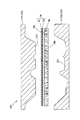
FIG. 4 is a side view illustrating the main part of the
形成される緩衝材40は、図5に示すように各ひだM2の折り返し面が緩衝材の幅方向D2及び厚み方向D3を通る面に合わせられ、繊維45,46が厚み方向D3へ配向している。折り返し部分47が集合した表面40a及び裏面40bは、ひだM2の積層方向D1に沿って形成されている。ここで、繊維45,46が厚み方向D3へ配向されていることは、繊維45,46の配列方向が表面40a及び裏面40bに対して直交する方向へ比較的揃っていることを意味し、繊維の折り返し部分47を有することを含む。
As shown in FIG. 5, the formed
緩衝材40を形成するための繊維45,46は、合成樹脂(エラストマーを含む)の繊維、合成樹脂に添加剤を添加した繊維、無機繊維、反毛繊維、等を用いることができる。
As the
主繊維45は、熱可塑性樹脂(熱可塑性エラストマーを含む)の繊維、熱可塑性樹脂に添加剤を添加した繊維、無機繊維、反毛繊維、等を用いることができ、PET等のポリエステル、PP等のポリオレフィン、ポリアミド、等の熱可塑性樹脂からなる繊維、これらの熱可塑性樹脂を変性させて融点を調整した熱可塑性樹脂からなる繊維、ガラス繊維、レーヨン繊維、衣料反毛繊維、さらに添加剤を添加した材質の繊維、これらの繊維の組合せ、等を用いることができる。主繊維45の繊維径は5〜60μm程度とすることができ、主繊維45の繊維長は10〜100mm程度とすることができる。
試験を行ったところ、主繊維45の少なくとも一部に反毛繊維(好ましくは衣料反毛繊維)を用いることにより緩衝材40の吸音性が向上することが判った。
The
As a result of the test, it was found that the sound absorbing property of the
接着性繊維46は、熱可塑性樹脂の繊維、熱可塑性樹脂に添加剤を添加した繊維、等を用いることができ、PET等のポリエステル、PPやPE(ポリエチレン)等のポリオレフィン、ポリアミド、等の熱可塑性樹脂からなる繊維、これらの熱可塑性樹脂を変性させて融点を調整した熱可塑性樹脂からなる繊維、さらに添加剤を添加した材質の繊維、等を用いることができる。主繊維が熱可塑性繊維である場合、接着性繊維には主繊維よりも低い融点を持つ熱可塑性の繊維を用いるのが好ましい。例えば、接着性繊維に主繊維と相溶性のある繊維を用いると、主繊維と接着性繊維との接着性が良好になり、緩衝材層50に十分な形状保持性を付与することができる。接着性繊維の融点は、100〜220℃程度とすることができる。
また、接着性繊維に使用可能な繊維を鞘部とし、該鞘部よりも融点の高い芯部の外周を該鞘部で囲んだ芯鞘構造の繊維を接着性繊維46として用いてもよい。この場合、芯部には、主繊維45に使用可能な繊維を用いることができる。
The
Alternatively, a fiber having a core-sheath structure in which a fiber that can be used as the adhesive fiber is used as a sheath and the outer periphery of the core having a melting point higher than that of the sheath is surrounded by the sheath may be used as the
接着性繊維46の繊維径は10〜45μm程度とすることができ、接着性繊維46の繊維長は10〜100mm程度とすることができる。主繊維45と接着性繊維46の配合比は、主繊維を30〜95重量%程度、接着性繊維を5〜70重量%程度とすることができる。
なお、接着性繊維の代わりに繊維状でないバインダを用いて緩衝材40を形成してもよい。
The fiber diameter of the
In addition, you may form the
緩衝材40の目付けは、300〜1500g/m2の範囲とすることが好ましく、500〜800g/m2の範囲とすることがさらに好ましい。また、緩衝材40の厚みは、10〜50mmの間で適用される車両形状に応じて適宜設計される。緩衝材40の密度は、0.01〜0.15g/cm 3の範囲とすることが好ましく、0.02〜0.08g/cm 3の範囲とすることがさらに好ましい。
緩衝材40の圧縮強度を実測したところ、密度が0.01〜0.15g/cm 3のときに1.5〜40kPaとなり、0.02〜0.08g/cm 3のときに2〜15kPaとなった。これに対して、繊維が厚み方向と直交する方向に配向した従来のフェルトの圧縮強度を実測したところ、密度0.055g/cm 3のときに2kPaとなった。また、主に嵩上材として従来用いられているウレタンスラブフォーム等の廃材にイソシアネート等のバインダーを散布して加熱成形されるウレタンチップモールドであっても、密度0.15g/cm 3のときに圧縮強度が25kPaとなった。このように、緩衝材40は、ウレタンチップモールドのような従来品と比べても低密度で同等の圧縮強度が得られることがわかる。
ここで、上述の圧縮強度は、島津製作所製の精密万能試験機AG-500Aを使用して25%ひずみ時の圧縮応力を測定して得られる値である。この測定の試験条件は、試験片サイズが50mm×50mm×厚さ20mmであり、圧縮速度が10mm/minであり、圧縮部位が全面、予備圧縮無しである。
プレス成形後の緩衝材層50の厚みは、プレス成形前の緩衝材40の厚みの50〜90%であることが好ましい。厚みが50%以上であると、厚み方向へ繊維が配行された繊維構造がプレス成形により破壊され難く、より高い圧縮強度を得ることができるため、好ましい。また、厚みが90%以下であると、プレス成形により隣接層と接着するための良好な反発力が得られ、良好な接着強度が得られるため、好ましい。
Basis weight of the
Was measured compressive strength of the
Here, the above-described compressive strength is a value obtained by measuring the compressive stress at 25% strain using a precision universal testing machine AG-500A manufactured by Shimadzu Corporation. The test conditions for this measurement are: the test piece size is 50 mm × 50 mm ×
The thickness of the
緩衝材層50を形成するための緩衝材は、厚み方向へ繊維が配向されていればよい。そこで、図6に示すように、上述した緩衝材40の表面40a及び裏面40bの折り返し部分47を切除したような緩衝材41を用いてもよい。
The buffer material for forming the
なお、意匠層30が車室SP1の底部に配置されるカーペットであり、緩衝材40が厚み方向へ繰り返しウェブが折り返されてひだM2が形成された波形形状とされている場合、図7に示すように、プレス成形する緩衝材40のひだM2の積層方向D1は、車幅方向に向いているのが好ましい。すなわち、図7に示すフロアカーペットの緩衝材層は、ひだM2の積層方向D1を車室SP1の車幅方向に向けた緩衝材40がプレス成形されることにより形成される。
自動車のフロア部の車体パネル80における車幅方向の中央部には、図2で示したように上へ膨出して前後に延びたトンネル部TU1が形成されている。これにより、車体パネル80の車幅方向に沿った垂直断面(例えば図2のA1−A1断面)における上下の凹凸は、車体パネル80の前後方向に沿った垂直断面(例えば図3のA2−A2断面)における上下の凹凸よりも大きくなっている。そこで、緩衝材40のひだM2の積層方向D1を車幅方向に向けることにより、プレス成形時にひだM2がアコーディオン状に展開するため、深い凹凸形状への追従性が向上する。図2で示したように、車体パネル80の車幅方向の両縁部81,81が車幅方向外側に向かって立ち上がっている場合も、同様の効果が得られる。
In addition, when the
As shown in FIG. 2, a tunnel portion TU <b> 1 that bulges upward and extends back and forth is formed in the vehicle width direction center portion of the
(2)車両用成形敷設内装材の製造方法、並びに、作用及び効果:
図8は、フロアカーペット10の製造方法の一例を示している。本フロアカーペットの製造工程は、成形前のカーペット本体20の原反ロールが所定の場所に置かれ、形成するフロアカーペット10の大きさに合わせて切断した成形前の緩衝材40がカットフェルト置き場に置かれた状態で、開始される。
(2) Manufacturing method of molded laying interior material for vehicle, operation and effect:
FIG. 8 shows an example of a method for manufacturing the
まず、カーペット本体の原反ロールからカーペット本体20が裁断機に搬入され(工程S1)、形成するフロアカーペット10の大きさに合わせてカーペット本体20が定尺に裁断される(工程S2)。裁断されたカーペット本体20は、赤外線ヒーター等の加熱機に搬入され、輻射加熱等により両面加熱されて、基層25が軟化する(工程S3)。加熱軟化したカーペット本体20は、図9に示すようなプレス成形機200に搬入される(工程S4)。
一方、カットフェルト置き場の緩衝材40は、サクションヒーター(熱風循環ヒーター)等の加熱機に搬入され(工程S5)、熱風加熱等により加熱されて、接着性繊維46が軟化する(工程S6)。加熱された緩衝材40は、プレス成形機200に搬入される(工程S7)。
フロアカーペット10の製造方法は、上記方法に限定されない。例えば、工程S3において、カーペット本体20をサクションヒーターで加熱してもよい。また、カーペット本体20と緩衝材40を重ねた状態でサクションヒーターによって同時に加熱しても良い。この際に十分な熱量を確保するため、サクションヒーターによる加熱に加えて赤外線ヒーターによる輻射加熱を同時に行うことも好ましい。
First, the
On the other hand, the
The manufacturing method of the
図9は、カーペット本体20と緩衝材40を重ねた状態で同時にプレス成形する場合の様子を模式的に示す垂直端面図である。図9に示すプレス成形機200は、プレス成形型210を構成する上型212及び下型214が近接及び離反可能に設けられている。ここで、上型212は、フロアカーペットの車室側の凹凸形状31に合わせた成形面213を下面に有する金型とされている。下型214は、フロアカーペットの車体パネル側の凹凸形状51に合わせた成形面215を上面に有する金型とされている。加熱されたカーペット本体20及び緩衝材40は、上型212側にカーペット本体20が配置され、下型214側に緩衝材40が配置される。むろん、カーペット本体の基層25と緩衝材の表面40a(又は裏面40b)とが対向して配置され、カーペット本体のパイル26が上型212に対向して配置され、緩衝材の裏面40b(又は表面40a)が下型214に対向して配置される。間にカーペット本体20及び緩衝材40を配置した両型212,214を近接させると、トリミング前のフロアカーペット10がプレス成形される。この工程は、図8に示す工程S8に相当する。
緩衝材40に接着性繊維46等のバインダが含まれている場合、カーペット本体の基層25に接着性の裏打ちが無くても、緩衝材40のバインダによりカーペット層30と緩衝材層50とが接着する。
FIG. 9 is a vertical end view schematically showing a state in which the
When the
トリミング前のフロアカーペット10は、冷却後にプレス成形機200から取り出されて外周裁断機へ搬入される(工程S9)。脱型後、トリミング前のフロアカーペット10は、外周裁断機で外周が裁断される(工程S10)。これにより、図10に示すようなフロアカーペット10が形成される。尚、工程S10における裁断方法は、裁断刃による裁断またはウォータージェット裁断とすることができる。また、工程S9及び工程S10を省略して、工程S8の型212,214を近接させた、フロアカーペット10がプレス成形された状態で、カッターを用いた手裁断によって外周を裁断してもよい。
フロアカーペット10を形成するための緩衝材40に厚み方向D3へ繊維が配向された繊維構造体が用いられているので、緩衝材40がプレス成形されても緩衝材層50が厚み方向D3への深い成形に追従し、緩衝材層50の厚みが部分的に変わっている。これにより、緩衝材層50は、上述したプレス成形により車体パネル80側の凹凸形状51が形成され、固化した接着性繊維46により凹凸形状51が保持される。むろん、カーペット層30は、上述したプレス成形により車室SP1側の凹凸形状31が形成され、固化した基層25によりパイル26の凹凸形状31が保持される。従って、形成されるフロアカーペット10は、凹凸形状31に保持されたカーペット層30と凹凸形状51に保持された緩衝材層50とが少なくとも積層されて一体化されている。
The
Since the fiber structure in which fibers are oriented in the thickness direction D3 is used for the
以上説明したように、上記フロアカーペット10に例示される車両用成形敷設内装材は、車体パネルの凹凸を埋める緩衝材層が車両用成形敷設内装材のプレス成形と同時に一体成形されるため、従来のようにフェルトを後貼りすることが不要となり、製造工数及び製造コストを低減させることが可能となり、緩衝材層の位置ずれ等の発生を可及的に低減することも可能となる。また、緩衝材層に厚み方向へ繊維が配向した繊維成形体が用いられているので、厚み方向への深い絞り変形が可能となり、車体パネルに形成された深い凹凸に追従した緩衝材層が一体化された新規な車両用成形敷設内装材を提供することができる。
As described above, the molded laying interior material for a vehicle exemplified by the
なお、従来のようにフェルトの構成繊維がカーペット本体の裏面に並行して配向している場合、乗員の足踏み等により厚み方向へ継続的に力を受けると、フェルトが厚み方向に潰されて元の厚みに回復できなくなる、所謂「へたり」が発生し易い。従って、従来のフェルトは、所要の踏み心地等の感触を確保するために高密度にすることが必要である。このため、従来のフロアカーペットは、製品重量が増加することとなり、また、車体パネルの凹凸形状に対応させるために異なる厚みのフェルトを裏面に複数貼る必要がある。このことは、フロアカーペットの部位によって厚み方向の流れ抵抗差が大きくなることに繋がり、防音性能の最適設計を困難にさせることとなる。
本車両用成形敷設内装材は、緩衝材層の繊維が厚み方向へ配列されているため、厚み方向の反発力が高く、従来よりも低密度で所要の踏み心地性や耐へたり性を確保することができる。このため、本車両用成形敷設内装材は、密度を低減させて軽量化させることが可能となり、低コスト化を図ることができるといった優れた効果が得られる。
In addition, when the felt constituent fibers are oriented in parallel with the back surface of the carpet body as in the prior art, if the force is continuously applied in the thickness direction due to the stepping of the occupant, the felt is crushed in the thickness direction and the original The so-called “sagging” that cannot be recovered to the thickness is likely to occur. Therefore, the conventional felt needs to have a high density in order to ensure a feeling such as a required treading feeling. For this reason, the product weight of the conventional floor carpet increases, and a plurality of felts having different thicknesses need to be pasted on the back surface in order to correspond to the uneven shape of the vehicle body panel. This leads to an increase in the flow resistance difference in the thickness direction depending on the portion of the floor carpet, and makes it difficult to optimally design the soundproofing performance.
The molded laying interior material for this vehicle has a high resilience in the thickness direction because the fibers of the cushioning material layer are arranged in the thickness direction, ensuring the required stepping comfort and sag resistance at a lower density than before. can do. For this reason, the molded laying interior material for a vehicle can be reduced in density and reduced in weight, and an excellent effect can be obtained, such as cost reduction.
また、本車両用成形敷設内装材は、従来のフェルトに比べて緩衝材を低密度とすることができるため、成形時に高いプレス圧をかける必要が無く、成形コストを低減することも可能となる。 Further, the molded laying interior material for this vehicle can reduce the density of the cushioning material as compared with the conventional felt, so that it is not necessary to apply a high press pressure at the time of molding, and the molding cost can be reduced. .
(3)変形例:
なお、本発明は、種々の変形例が考えられる。
例えば、本発明を適用可能な車両用成形敷設内装材は、フロアカーペット以外にも、ドアトリム、ラゲージサイドトリム、ピラーガーニッシュ内装材といった側壁トリム、ダッシュサイレンサ、ルーフライナ内装材、等でもよい。従って、意匠層を形成するための意匠材は、カーペット地の他、不織布、織物、編物、レザー、等でもよい。これらの意匠材から、不織布層、織物層、編物層、レザー層、等の意匠層が形成される。
上述した意匠層及び緩衝材層は、別々にプレス成形された後に接着されてもよい。また、緩衝材のみをプレス成形して緩衝材層を形成した後に該緩衝材層と意匠材とを少なくとも重ねて一緒にプレス成形してもよい。さらに、意匠材のみをプレス成形して意匠層のみを形成した後に該意匠層と緩衝材とを少なくとも重ねて一緒にプレス成形してもよい。これらの方法により形成される車両用成形敷設内装材も、本発明に含まれる。
車両用成形敷設内装材には、意匠層と緩衝材層との間に別の層が設けられてもよい。
(3) Modification:
The present invention can be modified in various ways.
For example, the molded laying interior material for vehicles to which the present invention can be applied may be a side wall trim such as a door trim, a luggage side trim, and a pillar garnish interior material, a dash silencer, a roof liner interior material, and the like in addition to a floor carpet. Therefore, the design material for forming the design layer may be non-woven fabric, woven fabric, knitted fabric, leather, etc., in addition to carpet. Design layers such as a nonwoven fabric layer, a woven fabric layer, a knitted layer, and a leather layer are formed from these design materials.
The design layer and the buffer material layer described above may be bonded after being separately press-molded. Alternatively, after the buffer material only is press-molded to form the buffer material layer, the buffer material layer and the design material may be overlapped and press-molded together. Furthermore, after only the design material is press-molded to form only the design layer, the design layer and the buffer material may be overlapped and press-molded together. A molded laying interior material for a vehicle formed by these methods is also included in the present invention.
Another layer may be provided between the design layer and the cushioning material layer in the molded laying interior material for a vehicle.
図11は、カーペット層(意匠層)30と緩衝材層50との間に開孔樹脂層61及び吸音層62を設けたフロアカーペット11を示している。図11に示すフロアカーペット11は、図1のA2−A2に相当する位置で切断したときの垂直端面を示している。本フロアカーペット11は、車室SP1から車体パネル80に向かって順にカーペット層(意匠層)30、開孔樹脂層61、吸音層62、緩衝材層50が積層されて一体化されている。
本変形例のカーペット層30を形成するためのカーペット本体(意匠材)20(図9参照)は、該カーペット本体20の厚み方向への通気性を有する。この通気性は、カーペット本体20の厚み方向への流れ抵抗値(ISO 9053に規定される流れ抵抗値)として50〜500N・s/m3が好ましい。カーペット本体の基層25に通気性を阻害する裏打ちを設けないようにして、パイル26の繊維長や繊維径を調整したり、ニードルパンチカーペットの場合はニードリングの度合いを調整したりすることにより、カーペット本体20の通気性を調節することができる。
FIG. 11 shows the
The carpet body (design material) 20 (see FIG. 9) for forming the
開孔樹脂層61は、厚み方向に貫通した開孔61aが複数形成され、カーペット層30と吸音層62とを高通気状態で接着する。開孔樹脂層61を形成する材料は、樹脂(エラストマーを含む)のみからなる材料でもよいし、添加剤が添加された材料でもよい。前記樹脂は、合成樹脂が好ましく、熱可塑性樹脂が特に好ましい。この熱可塑性樹脂は、低融点(100〜300℃)の熱可塑性樹脂が好ましく、PEやPPといったオレフィン系樹脂、オレフィン系熱可塑性エラストマー、変成ポリエステル、等を用いることができる。
上述した材料のフィルムに多数の微小開孔を形成すると、開孔樹脂層61を形成することができる。
A plurality of
When a large number of minute openings are formed in the film of the above-described material, the opening
開孔樹脂層の各開孔61aの直径は、0.5〜3mm程度とすることができる。単位面積当たりの開孔61aの数は、40〜500個/cm2程度とすることができる。開孔樹脂層61の流れ抵抗値は、良好な吸音性能を発揮させる観点から、300〜3500N・s/m3が好ましい。各開孔61aの直径や開孔61aの数を調整することにより、開孔樹脂層61の流れ抵抗値を前述の範囲内にすることができる。例えば、各開孔61aの直径を大きくしたり開孔61aの数を多くしたりすると流れ抵抗値を小さくさせることができ、各開孔61aの直径を小さくしたり開孔61aの数を少なくしたりすると流れ抵抗値を大きくさせることができる。
The diameter of each
吸音層62は、開孔樹脂層61と緩衝材層50との間に積層されている。吸音層62は、吸音性が付与され、フロアカーペット11の形状を保持する。吸音層62はカーペット層30よりも剛性が高くされ、フロアカーペット11はプレス成形時に吸音層62を賦形することによって本質的に形状が保持される。
繊維を集合させて成形して吸音層62とする場合、該繊維は、合成樹脂(エラストマーを含む)の繊維、合成樹脂に添加剤を添加した繊維、無機繊維、反毛繊維、等を用いることができ、PET等のポリエステル、PP等のポリオレフィン、ポリアミド、等の熱可塑性樹脂からなる繊維、これらの熱可塑性樹脂を変性させて融点を調整した熱可塑性樹脂からなる繊維、ガラス繊維、レーヨン繊維、衣料反毛繊維、さらに添加剤を添加した材質の繊維、これらの繊維の組合せ、等を用いることができる。繊維径は5〜60μm程度とすることができ、繊維長は10〜100mm程度とすることができる。
The
When the fibers are assembled and formed into the
吸音層62の厚みは、2〜5mm程度とすることができる。吸音層62の密度は、50〜300kg/m3とすることができる。吸音層62の流れ抵抗値は、50〜500N・s/m3が好ましい。
The thickness of the
本フロアカーペット11は、例えば、以下のようにして製造することができる。
まず、開孔樹脂層61となる樹脂材料をフィルム状に押し出し、吸音層62となる成形前の吸音材に重ねてローラー等で押圧して積層する。続いて、長尺ドラムの外周に多数の熱針を植設した開孔機によって、所要の開孔径、開孔数で開孔61aを樹脂フィルムに形成する。次に、この積層物の樹脂フィルム側に基層25を対向させて通気性のカーペット本体20を重ねるとともに、該積層物の吸音材側に厚み方向D3へ繊維45,46が配向した緩衝材40を重ね、この状態でサクションヒーターにより該積層物とカーペット本体20と緩衝材層50とを同時に熱風加熱する。加熱後、これらを図9で示したような型212,214の間に搬入し、プレス成形を行う。冷却後、トリミング前のフロアカーペット11を外周裁断機へ搬入し、外周をウォータージェットで裁断すると、フロアカーペット11が形成される。
The
First, the resin material that becomes the
上述したフロアカーペット11の製造方法は、特開2007-161153号公報に示された製法によっても行うことができる。樹脂フィルムに開孔61aを形成する際には、吸音材に重ねる前に開孔機によって形成してもよい。熱針の代わりに、非加熱の針刺し加工を行ってもよい。
また、特開2007-161153号公報に示されるように、パウダー方式、メルト繊維方式、常温ニードリング方式により開孔樹脂層を形成してもよい。
The manufacturing method of the
Further, as disclosed in JP-A-2007-161153, the open resin layer may be formed by a powder method, a melt fiber method, or a room temperature needling method.
以上説明したように、上記フロアカーペット11に例示される車両用成形敷設内装材は、意匠層と緩衝材層との間に開孔樹脂層が設けられ、意匠層が通気性とされていることにより、車室からの音が吸音層や緩衝材層に入射して吸収される。すなわち、車両用成形敷設内装材で反射して車室に戻る車室からの音が少なくなるので、本車両用成形敷設内装材は、吸音性が向上している。
また、開孔樹脂層で車両用成形敷設内装材の通気度を制御することが可能となり、車両に応じた吸音性能を付与することができる。ここで、緩衝材層は繊維が厚み方向に配向されている繊維成形体で低密度とされているため、プレス成形時に圧縮量の大きい部位の反撥力を低減することができ、開孔樹脂層に設けた開孔が潰れて塞がれる可能性を可及的に低減することができる。
さらに、緩衝材層50は、厚み方向のクッション性が優れているため、圧縮量が小さい部位においても一定の反発力が得られる。従って、緩衝材層の接着力不足による剥がれが生じる可能性を低減させることも可能となる。
As described above, the molded laying interior material for a vehicle exemplified by the
In addition, it is possible to control the air permeability of the molded laying interior material for a vehicle with the open resin layer, and it is possible to provide a sound absorbing performance corresponding to the vehicle. Here, the buffer material layer is a fiber molded body in which fibers are oriented in the thickness direction, and has a low density. It is possible to reduce as much as possible the possibility of crushing and closing the aperture provided in the.
Furthermore, since the
なお、吸音層62と緩衝材層50との間に非通気性の樹脂層を積層してもよい。この非通気性の樹脂層は、遮音層となり、車外から車室へ侵入しようとする騒音を遮断する。これにより、車室内の静粛性を高めることができる。また、非通気性の樹脂層は、吸音層62と緩衝材層50とを接着する機能も有する。
A non-breathable resin layer may be laminated between the
さらに、図12は、カーペット層(意匠層)30と緩衝材層50との間に開孔樹脂層61のみを設けたフロアカーペット12を示している。図12に示すフロアカーペット12も、図1のA2−A2に相当する位置で切断したときの垂直端面を示している。すなわち、本フロアカーペット12は、車室SP1から車体パネル80に向かって順にカーペット層(意匠層)30、開孔樹脂層61、緩衝材層50が積層されて一体化されている。各層は、図11で示したフロアカーペット11と同様の構成とすることができる。
Further, FIG. 12 shows the
本フロアカーペット12は、例えば、以下のようにして製造することができる。
まず、開孔樹脂層61となる樹脂材料をフィルム状に押し出し、緩衝材40に重ねてローラー等で押圧して積層する。続いて、長尺ドラムの外周に多数の熱針を植設した開孔機によって、所要の開孔径、開孔数で開孔61aを樹脂フィルムに形成する。次に、この積層物の樹脂フィルム側に基層25を対向させて通気性のカーペット本体20を重ね、この状態でサクションヒーターにより該積層物とカーペット本体20とを同時に熱風加熱する。加熱後、プレス成形を行い、冷却後に外周を裁断すると、フロアカーペット12が形成される。本フロアカーペット12の製造方法も、特開2007-161153号公報に示された各種製法によって行うことができる。
The
First, the resin material to be the
本フロアカーペット12に例示される車両用成形敷設内装材は、意匠層と緩衝材層との間に開孔樹脂層が設けられ、意匠層が通気性とされていることにより、車室からの音が緩衝材層に入射して吸収される。すなわち、車両用成形敷設内装材で反射して車室に戻る車室からの音が少なくなるので、本車両用成形敷設内装材は、吸音性が向上している。
The molded laying interior material for a vehicle exemplified in the
さらに、図13は、車体パネル80側の面32にフェルト70を後貼りしたフロアカーペット13を示している。本フロアカーペット13は、緩衝材層50が車体パネル80側の面の一部、例えば、30〜70%の範囲に積層されている。本フロアカーペット13は、プレス成形の後に緩衝材層50が設けられていない車体パネル80側の面32にフェルト70が後貼りされている。フェルト70は、構成繊維がフェルト面に対して略平行に配向した従来のフェルトでもよいし、上述した緩衝材40のように構成繊維が厚み方向へ配向した繊維構造体でもよい。また、フェルト70は、平物のフェルトでもよいし、成形されたフェルトでもよい。
Further, FIG. 13 shows the
フェルト70を用いることによって、自動車のフロア面の形状を変更する場合であってもプレス成形型を変えずに対応することができる。例えば、フロアパネル上にダクトの設定がある場合とない場合とがあるように、同じ車両であってもグレードによってフロア面の凹凸形状が一部異なる場合がある。本フロアカーペット13に例示される車両用成形敷設内装材は、車体パネルの形状が一部変わっても、フェルトを後貼りすることにより一つの成形型で対応することができ、車両用成形敷設内装材の裏面形状の自由度を高めることができ、製造コストを低減させることができる。
なお、プレス成形の後に緩衝材層50が設けられた車体パネル80側の面52にフェルト70を後貼りしてもよい。
By using the felt 70, even if the shape of the floor surface of the automobile is changed, it can be handled without changing the press mold. For example, as in the case where the duct is set on the floor panel, there are cases where the uneven shape of the floor surface is partially different depending on the grade even in the same vehicle. The molded laying interior material for a vehicle exemplified in the
In addition, the felt 70 may be post-applied to the
図14は、緩衝材層50の車体パネル80側の面52にフェルト70を後貼りしたフロアカーペット14を示している。このフェルト70は、構成繊維がフェルト面に対して略平行に配向した従来のフェルトとされている。
図15は、緩衝材層50の車体パネル80側の面52に緩衝材42を後貼りしたフロアカーペット15を示している。この緩衝材42は、上述した緩衝材40のように構成繊維が厚み方向へ配向した繊維構造体とされている。
FIG. 14 shows the
FIG. 15 shows the
上記フロアカーペット14,15に例示される車両用成形敷設内装材は、車体パネルに局所的に深い凹部がある場合等にフェルト70又は緩衝材42で車体パネルの深い凹凸形状に対応させることができ、一つの成形型で対応することができる。従って、本変形例は、さらに、フロアカーペットの踏み心地性等、車両用成形敷設内装材の良好な感触を確保することができる。
The molded laying interior material for vehicles exemplified in the
緩衝材層50に緩衝材42を後貼りする場合、図16に示すように、構成繊維(図4に示す繊維45,46)の折り畳み方向を直交する向きとする等、構成繊維の折り畳み方向を異ならせる向きに後貼りするのが好ましい。これにより、緩衝材層50及び緩衝材42の反発力が高まり、フロアカーペットの踏み心地性及び耐へたり性が高められる等、車両用成形敷設内装材の良好な感触及び耐へたり性が高められる。
When the
(4)緩衝材の吸音試験:
以下、本車両用成形敷設内装材を形成するために使用可能な緩衝材の吸音試験の実施例を示して具体的に本発明を説明するが、本発明は実施例により限定されるものではない。
(4) Sound absorption test of cushioning material:
Hereinafter, the present invention will be specifically described with reference to an example of a sound absorption test of a cushioning material that can be used to form the molded laying interior material for a vehicle. However, the present invention is not limited to the example. .
[緩衝材サンプルの調整]
実施例1の主繊維には、PET繊維及び衣料反毛繊維(ロット1)を用いた。実施例2の主繊維には、衣料反毛繊維(ロット1)のみを用いた。実施例3の主繊維には、PET繊維及び衣料反毛繊維(ロット2)を用いた。実施例4の主繊維には、衣料反毛繊維(ロット2)のみを用いた。比較例の主繊維には、PET繊維のみを用いた。実施例1〜4及び比較例の接着性繊維には、PET/PETの芯鞘繊維を用いた。
[Adjustment of buffer material sample]
As the main fibers of Example 1, PET fibers and clothing anti-hair fibers (Lot 1) were used. For the main fiber of Example 2, only clothing anti-fiber fibers (lot 1) were used. As the main fibers of Example 3, PET fibers and clothing anti-hair fibers (Lot 2) were used. For the main fibers of Example 4, only clothing anti-fiber fibers (Lot 2) were used. Only PET fiber was used for the main fiber of the comparative example. PET / PET core-sheath fibers were used for the adhesive fibers of Examples 1 to 4 and Comparative Example.
以下の配合比(単位;重量%)の繊維ウェブを特表2008-538130号公報に記載のテキスタイルラップ装置でプリーツ状に折り畳み、目付け600g/m2、厚み20mmの緩衝材サンプルを形成した。

[吸音性の評価方法]
実施例1〜4及び比較例の緩衝材サンプルを用い、緩衝材の厚み方向へノイズを入射させたときの200〜6300Hzにおける垂直入射吸音率を測定した。垂直入射吸音率は、JIS A1405:2007-2「音響管による吸音率及びインピーダンスの測定−第2部:伝達関数法」に規定される管内法に準拠して1/3オクターブバンド中心周波数(Hz)の吸音率を測定した。
[Sound absorption evaluation method]
Using the buffer material samples of Examples 1 to 4 and the comparative example, the normal incident sound absorption coefficient at 200 to 6300 Hz when noise was incident in the thickness direction of the buffer material was measured. The normal incidence sound absorption coefficient is 1/3 octave band center frequency (Hz) in accordance with the pipe method specified in JIS A1405: 2007-2 “Measurement of sound absorption coefficient and impedance by acoustic tube—Part 2: Transfer function method” ) Was measured.
[結果]
結果を、図17に示す。図17は、各実施例及び比較例について200〜6300Hzの1/3オクターブバンド毎の中心周波数(単位:Hz)に対する垂直入射吸音率(単位:無し)の測定結果をグラフにより示している。
上記実施例より、緩衝材に衣料反毛繊維を入れると吸音性能が向上することが判った。従って、本発明の車両用成形敷設内装材は、緩衝材層に反毛繊維を入れると吸音性能が向上することが期待される。
[result]
The results are shown in FIG. FIG. 17 is a graph showing the measurement results of the normal incident sound absorption coefficient (unit: none) with respect to the center frequency (unit: Hz) for each 1/3 octave band of 200 to 6300 Hz for each example and comparative example.
From the above examples, it was found that the sound absorbing performance was improved by adding clothing anti-hair fibers to the cushioning material. Therefore, the molded laying interior material for a vehicle of the present invention is expected to have improved sound absorption performance when an anti-fiber is put in the cushioning material layer.
(5)まとめ:
上述した実施形態により、本発明は、車室に面する意匠層と車体パネルに面する緩衝材層とを有する車両用成形敷設内装材であって、
前記意匠層となる成形前の意匠材と、厚み方向へ繊維が配向された繊維構造体とされるとともに前記緩衝材層となる成形前の緩衝材と、が少なくとも重ねられた状態で同時にプレス成形され、該プレス成形により前記車室側の凹凸形状が形成された前記意匠層と、前記プレス成形により前記車体パネル側の凹凸形状が形成された前記緩衝材層と、が少なくとも積層されて一体化された、側面1を有する。
(5) Summary:
According to the embodiment described above, the present invention is a molded laying interior material for a vehicle having a design layer facing a passenger compartment and a cushioning material layer facing a vehicle body panel,
Simultaneously press-molding the design material before molding serving as the design layer and the cushioning material before molding serving as the cushioning material layer with a fiber structure in which fibers are oriented in the thickness direction. The design layer in which the concave-convex shape on the vehicle compartment side is formed by the press molding and the cushioning material layer in which the concave-convex shape on the vehicle body panel side is formed by the press molding are laminated and integrated at least. And has a side surface 1.
また、本発明は、車室に面する意匠層と車体パネルに面する緩衝材層とを有する車両用成形敷設内装材であって、
前記意匠層となる成形前の意匠材と、厚み方向へ繰り返しウェブが折り返された波形形状とされるとともに前記緩衝材層となる成形前の緩衝材と、が少なくとも重ねられた状態で同時にプレス成形され、該プレス成形により前記車室側の凹凸形状が形成された前記意匠層と、前記プレス成形により前記車体パネル側の凹凸形状が形成された前記緩衝材層と、が少なくとも積層されて一体化された、側面2を有する。
Further, the present invention is a molded laying interior material for a vehicle having a design layer facing the vehicle compartment and a cushioning material layer facing the vehicle body panel,
Simultaneously press-molding the design material before molding to be the design layer and the waveform material in which the web is repeatedly folded back in the thickness direction and the cushioning material to be the cushioning material layer before molding are at least overlapped The design layer in which the concave-convex shape on the vehicle compartment side is formed by the press molding and the cushioning material layer in which the concave-convex shape on the vehicle body panel side is formed by the press molding are laminated and integrated at least. And has a
さらに、本発明は、車室に面する意匠層と車体パネルに面する緩衝材層とを有する車両用成形敷設内装材であって、
前記意匠層となる成形前の意匠材と、厚み方向へ繊維が配向された繊維構造体とされた緩衝材が第一のプレス成形により前記車体パネル側の凹凸形状が形成された前記緩衝材層と、が少なくとも重ねられた状態で第二のプレス成形が行われ、該第二のプレス成形により前記車室側の凹凸形状が形成された前記意匠層と、前記緩衝材層と、が少なくとも積層されて一体化された、側面3を有する。
Furthermore, the present invention is a molded laying interior material for a vehicle having a design layer facing the passenger compartment and a cushioning material layer facing the vehicle body panel,
The cushioning material layer in which the concave and convex shape on the side of the vehicle body panel is formed by first press molding of a cushioning material made into a design material before molding to be the design layer and a fiber structure in which fibers are oriented in the thickness direction And the second press molding is performed at least in a state of being stacked, and the design layer in which the concavo-convex shape on the passenger compartment side is formed by the second press molding and the buffer material layer are at least laminated. And has an integrated side surface 3.
さらに、本発明は、車室に面する意匠層と車体パネルに面する緩衝材層とを有する車両用成形敷設内装材であって、
前記意匠層となる成形前の意匠材と、厚み方向へ繰り返しウェブが折り返されて波形形状とされた緩衝材が第一のプレス成形により前記車体パネル側の凹凸形状が形成された前記緩衝材層と、が少なくとも重ねられた状態で第二のプレス成形が行われ、該第二のプレス成形により前記車室側の凹凸形状が形成された前記意匠層と、前記緩衝材層と、が少なくとも積層されて一体化された、側面4を有する。
Furthermore, the present invention is a molded laying interior material for a vehicle having a design layer facing the passenger compartment and a cushioning material layer facing the vehicle body panel,
The cushioning material layer in which the concave and convex shape on the vehicle body panel side is formed by the first press molding of the design material before molding to be the design layer and the cushioning material in which the web is repeatedly folded back in the thickness direction into a corrugated shape And the second press molding is performed at least in a state of being stacked, and the design layer in which the concavo-convex shape on the passenger compartment side is formed by the second press molding and the buffer material layer are at least laminated. And has an integrated
さらに、本発明は、車室に面する意匠層と車体パネルに面する緩衝材層とを有する車両用成形敷設内装材であって、
前記意匠層となる成形前の意匠材が第一のプレス成形により前記車室側の凹凸形状が形成された前記意匠層と、厚み方向へ繊維が配向された繊維構造体とされるとともに前記緩衝材層となる成形前の緩衝材と、が少なくとも重ねられた状態で第二のプレス成形が行われ、前記意匠層と、前記第二のプレス成形により前記車体パネル側の凹凸形状が形成された前記緩衝材層と、が少なくとも積層されて一体化された、側面5を有する。
Furthermore, the present invention is a molded laying interior material for a vehicle having a design layer facing the passenger compartment and a cushioning material layer facing the vehicle body panel,
The design material before molding to be the design layer is the design layer in which the concavo-convex shape on the passenger compartment side is formed by first press molding, and the fiber structure in which fibers are oriented in the thickness direction, and the buffer A second press molding is performed in a state where at least the buffer material before molding that becomes the material layer is overlapped, and the uneven shape on the vehicle body panel side is formed by the design layer and the second press molding. The buffer layer has at least a
さらに、本発明は、車室に面する意匠層と車体パネルに面する緩衝材層とを有する車両用成形敷設内装材であって、
前記意匠層となる成形前の意匠材が第一のプレス成形により前記車室側の凹凸形状が形成された前記意匠層と、厚み方向へ繰り返しウェブが折り返された波形形状とされるとともに前記緩衝材層となる成形前の緩衝材と、が少なくとも重ねられた状態で第二のプレス成形が行われ、前記意匠層と、前記第二のプレス成形により前記車体パネル側の凹凸形状が形成された前記緩衝材層と、が少なくとも積層されて一体化された、側面6を有する。
Furthermore, the present invention is a molded laying interior material for a vehicle having a design layer facing the passenger compartment and a cushioning material layer facing the vehicle body panel,
The design material before being formed as the design layer is formed into a corrugated shape in which the web side is repeatedly folded back in the thickness direction, and the buffer layer is formed with the design layer in which the concave-convex shape on the vehicle compartment side is formed by first press molding. A second press molding is performed in a state where at least the buffer material before molding that becomes the material layer is overlapped, and the uneven shape on the vehicle body panel side is formed by the design layer and the second press molding. The buffer layer has at least a side surface 6 laminated and integrated.
上述した側面1〜6により、車体パネルに形成された深い凹凸形状に追従した緩衝材層がプレス成形により一体化された新規な車両用成形敷設内装材を提供することができる。 By the side surfaces 1 to 6 described above, it is possible to provide a novel molded laying interior material for a vehicle in which a cushioning material layer following a deep uneven shape formed on the vehicle body panel is integrated by press molding.
なお、緩衝材に反毛繊維が含まれていなくても、得られる車両用成形敷設内装材は車体パネルに形成された深い凹凸形状に追従した緩衝材層が一体化された新規な内装材となる。
また、緩衝材を構成する繊維が一種類であっても、厚み方向へ配向されていれば、得られる車両用成形敷設内装材は車体パネルに形成された深い凹凸形状に追従した緩衝材層が一体化された新規な内装材となる。
すなわち、従属請求項に係る構成要件を有しておらず独立請求項に係る構成要件のみからなる車両用内装部品でも、上述した基本的な作用、効果が得られる。
Even if the cushioning material does not contain repellent fibers, the resulting molded laying interior material for a vehicle is a new interior material in which a cushioning material layer that follows the deep uneven shape formed on the vehicle body panel is integrated. Become.
Moreover, even if there is only one type of fiber constituting the cushioning material, if it is oriented in the thickness direction, the resulting molded laying interior material for the vehicle has a cushioning material layer that follows the deep irregular shape formed on the vehicle body panel. It becomes a new integrated interior material.
That is, the above-described basic functions and effects can be obtained even with an interior part for a vehicle that does not have the constituent requirements according to the dependent claims but only the constituent requirements according to the independent claims.
以上説明したように、本発明によると、種々の態様により、車体パネルに形成された深い凹凸形状に追従した緩衝材層が一体化された新規な車両用成形敷設内装材を提供することができる。
また、上述した実施形態及び変形例の中で開示した各構成を相互に置換したり組み合わせを変更したりして本発明を実施することも可能であり、公知技術並びに上述した実施形態及び変形例の中で開示した各構成を相互に置換したり組み合わせを変更したりして本発明を実施することも可能である。従って、本発明は、上述した実施形態や変形例に限られず、公知技術並びに上述した実施形態及び変形例の中で開示した各構成を相互に置換したり組み合わせを変更したりした構成等も含まれる。
As described above, according to the present invention, according to various aspects, it is possible to provide a novel molded laying interior material for a vehicle in which a cushioning material layer following a deep uneven shape formed on a vehicle body panel is integrated. .
In addition, it is also possible to implement the present invention by mutually replacing the configurations disclosed in the above-described embodiments and modifications, and changing the combination. It is also possible to carry out the present invention by substituting each component disclosed in the above or changing the combination. Therefore, the present invention is not limited to the above-described embodiments and modifications, and includes configurations in which the configurations disclosed in the publicly known technology and the above-described embodiments and modifications are mutually replaced or combinations thereof are changed. It is.
10,11,12,13,14,15…フロアカーペット(車両用成形敷設内装材)、
20…カーペット本体(意匠材)、25…基層、26…パイル、
30…カーペット層(意匠層)、31…車室側の凹凸形状、
32…緩衝材層が設けられていない車体パネル側の面、
40,41,42…緩衝材、40a…表面、40b…裏面、
45…主繊維、46…接着性繊維(バインダ)、47…折り返し部分、
50…緩衝材層、51…車体パネル側の凹凸形状、52…車体パネル側の面、
61…開孔樹脂層、62…吸音層、70…フェルト、
80…車体パネル、
200…プレス成形機、
D1…ひだの積層方向、D2…幅方向、D3…厚み方向、
M2…ひだ、
SP1…車室。
10, 11, 12, 13, 14, 15 ... floor carpet (molded interior material for vehicles),
20 ... carpet body (design material), 25 ... base layer, 26 ... pile,
30 ... Carpet layer (design layer), 31 ... Uneven shape on the passenger compartment side,
32 ... the surface on the side of the vehicle body panel where no cushioning material layer is provided,
40, 41, 42 ... cushioning material, 40a ... front surface, 40b ... back surface,
45 ... main fiber, 46 ... adhesive fiber (binder), 47 ... folded portion,
50 ... cushioning material layer, 51 ... uneven shape on the vehicle body panel side, 52 ... surface on the vehicle body panel side,
61 ... Open-hole resin layer, 62 ... Sound absorbing layer, 70 ... Felt,
80 ... body panel,
200 ... press molding machine,
D1 ... fold stacking direction, D2 ... width direction, D3 ... thickness direction,
M2 ... folds,
SP1 ... Car compartment.
Claims (3)
厚み方向に貫通した開孔が複数形成された開孔樹脂層が前記意匠層と前記緩衝材層との間に設けられ、前記意匠層と前記開孔樹脂層と前記緩衝材層とが少なくとも積層されて一体化され、厚み方向へ配向した繊維を有する前記緩衝材から形成された前記緩衝材層の厚みが部分的に変わっており、
前記カーペット本体の流れ抵抗値を50〜500N・s/m 3 とし、前記開孔の直径を0.5〜3mmとし、単位面積当たりの前記開孔の数を40〜500個/cm 2 とし、前記開孔樹脂層の流れ抵抗値を300〜3500N・s/m 3 とした、車両用成形敷設内装材。 Possess a buffer material layer facing the decorative layer and the body panel facing the passenger compartment, and the decorative layer in which a concavo-convex shape of the casing side is formed by the carpet body is press-molded, the fibers in the thickness direction And a cushioning material layer in which the concave and convex shape on the side of the vehicle body panel is formed by press molding a cushioning material that is oriented fiber structure, and is molded and laid for a vehicle. In interior materials ,
An aperture resin layer having a plurality of apertures penetrating in the thickness direction is provided between the design layer and the buffer material layer, and at least the design layer, the aperture resin layer, and the buffer material layer are laminated. The thickness of the cushioning material layer formed from the cushioning material having fibers that are integrated and oriented in the thickness direction is partially changed,
The flow resistance value of the carpet body is 50 to 500 N · s / m 3 , the diameter of the openings is 0.5 to 3 mm, and the number of openings per unit area is 40 to 500 pieces / cm 2 . A molded laying interior material for a vehicle in which the flow resistance value of the apertured resin layer is 300 to 3500 N · s / m 3 .
厚み方向に貫通した開孔が複数形成された開孔樹脂層が前記意匠層と前記緩衝材層との間に設けられ、前記意匠層と前記開孔樹脂層と前記緩衝材層とが少なくとも積層されて一体化され、厚み方向へ繰り返しウェブが折り返されて波形形状とされた前記緩衝材から形成された前記緩衝材層の厚みが部分的に変わっており、
前記カーペット本体の流れ抵抗値を50〜500N・s/m 3 とし、前記開孔の直径を0.5〜3mmとし、単位面積当たりの前記開孔の数を40〜500個/cm 2 とし、前記開孔樹脂層の流れ抵抗値を300〜3500N・s/m 3 とした、車両用成形敷設内装材。 Possess a buffer material layer facing the decorative layer and the body panel facing the passenger compartment, and the decorative layer in which a concavo-convex shape of the casing side is formed by the carpet body is press-molded repeatedly in the thickness direction Molded laying for a vehicle in which the cushioning material layer having a corrugated shape on the side of the vehicle body panel formed by press molding a corrugated cushioning material by folding the web is at least laminated and integrated In interior materials ,
An aperture resin layer having a plurality of apertures penetrating in the thickness direction is provided between the design layer and the buffer material layer, and at least the design layer, the aperture resin layer, and the buffer material layer are laminated. And the thickness of the cushioning material layer formed from the cushioning material which is formed into a wavy shape by repeatedly folding the web in the thickness direction is partially changed,
The flow resistance value of the carpet body is 50 to 500 N · s / m 3 , the diameter of the openings is 0.5 to 3 mm, and the number of openings per unit area is 40 to 500 pieces / cm 2 . A molded laying interior material for a vehicle in which the flow resistance value of the apertured resin layer is 300 to 3500 N · s / m 3 .
該吸音層の流れ抵抗値を50〜500N・s/m 3 とした、請求項1又は請求項2に記載の車両用成形敷設内装材。 A sound absorbing layer is further provided between the design layer and the cushioning material layer,
The flow resistance of the sound absorbing layer was 50~500N · s / m 3, the molded laying interior material for a vehicle according to claim 1 or claim 2.
Priority Applications (5)
| Application Number | Priority Date | Filing Date | Title |
|---|---|---|---|
| JP2010037091A JP5491232B2 (en) | 2010-02-23 | 2010-02-23 | Molded laying interior materials for vehicles |
| US13/004,895 US8727417B2 (en) | 2010-02-23 | 2011-01-12 | Molded laying interior material for vehicle |
| CA2728367A CA2728367C (en) | 2010-02-23 | 2011-01-17 | Molded laying interior material for vehicle |
| EP11151445.1A EP2361803B1 (en) | 2010-02-23 | 2011-01-19 | Molded laying interior material for vehicle |
| CN201110036193.2A CN102161330B (en) | 2010-02-23 | 2011-02-09 | Molded laying interior material for vehicle |
Applications Claiming Priority (1)
| Application Number | Priority Date | Filing Date | Title |
|---|---|---|---|
| JP2010037091A JP5491232B2 (en) | 2010-02-23 | 2010-02-23 | Molded laying interior materials for vehicles |
Publications (2)
| Publication Number | Publication Date |
|---|---|
| JP2011173446A JP2011173446A (en) | 2011-09-08 |
| JP5491232B2 true JP5491232B2 (en) | 2014-05-14 |
Family
ID=44247913
Family Applications (1)
| Application Number | Title | Priority Date | Filing Date |
|---|---|---|---|
| JP2010037091A Active JP5491232B2 (en) | 2010-02-23 | 2010-02-23 | Molded laying interior materials for vehicles |
Country Status (5)
| Country | Link |
|---|---|
| US (1) | US8727417B2 (en) |
| EP (1) | EP2361803B1 (en) |
| JP (1) | JP5491232B2 (en) |
| CN (1) | CN102161330B (en) |
| CA (1) | CA2728367C (en) |
Families Citing this family (23)
| Publication number | Priority date | Publication date | Assignee | Title |
|---|---|---|---|---|
| JP5520963B2 (en) | 2009-11-13 | 2014-06-11 | 株式会社Uacj | Plate material having concavo-convex portions, laminated structure using the same, and vehicle panel |
| JP5829112B2 (en) * | 2011-12-13 | 2015-12-09 | 林テレンプ株式会社 | Molded interior material for vehicle and manufacturing method thereof |
| JP5977574B2 (en) * | 2012-05-10 | 2016-08-24 | 林テレンプ株式会社 | Method for producing laying material and method for producing molded interior material for vehicle |
| CN103240864B (en) * | 2013-05-23 | 2015-12-09 | 柳州市方鑫汽车装饰件有限公司 | Car carpeting hot-press molding method |
| JP6426707B2 (en) * | 2014-03-25 | 2018-11-21 | 林テレンプ株式会社 | Automotive silencer |
| JP2016020158A (en) * | 2014-07-14 | 2016-02-04 | 寿屋フロンテ株式会社 | Vehicular interior material |
| EP3012155A1 (en) * | 2014-10-20 | 2016-04-27 | Autoneum Management AG | Main floor part for a small utility vehicle |
| JP6430284B2 (en) * | 2015-02-25 | 2018-11-28 | 林テレンプ株式会社 | Silencer for automobile and manufacturing method thereof |
| JP6564656B2 (en) * | 2015-09-08 | 2019-08-21 | 株式会社クラレ | Designable sheet and method for producing the designed sheet |
| US10807509B2 (en) | 2015-12-28 | 2020-10-20 | Thermoflex Corporation | Vehicle floor mat with supports for irregular vehicle floor |
| US10377068B2 (en) * | 2016-09-23 | 2019-08-13 | Inteva Products, Llc | Method and apparatus for non-woven trim panels |
| DE102017000638A1 (en) * | 2017-01-25 | 2018-07-26 | GM Global Technology Operations LLC | Insulation module for motor vehicle and motor vehicle |
| EP3636425A4 (en) * | 2017-06-09 | 2021-01-20 | Seiren Co., Ltd. | Composite material for vehicle interior |
| US20200232133A1 (en) * | 2017-07-18 | 2020-07-23 | Zephyros, Inc. | Nonwoven composite for high temperature applications requiring low flammability, smoke, and toxicity |
| FR3069210B1 (en) * | 2017-07-24 | 2020-12-11 | Faurecia Automotive Ind | AUTOMOTIVE VEHICLE SOUNDPROOFING PART AND ASSOCIATED MANUFACTURING PROCESS |
| JP7187053B2 (en) * | 2019-01-25 | 2022-12-12 | MT-Tec合同会社 | Vehicle interior materials |
| US11390226B2 (en) | 2020-07-17 | 2022-07-19 | Toyota Motor Engineering & Manufacturing North America, Inc. | Vehicle floor silencer with wall support element |
| KR20220061560A (en) * | 2020-11-06 | 2022-05-13 | 현대자동차주식회사 | Light and thin sound-absorbing material, and manufacturing method thereof |
| CN112677895A (en) * | 2021-01-20 | 2021-04-20 | 重庆长安汽车股份有限公司 | Automobile roof lining structure |
| CN114619935A (en) * | 2022-01-26 | 2022-06-14 | 上汽通用五菱汽车股份有限公司 | Matching structure of front carpet assembly, front floor and auxiliary instrument panel |
| CN114687060A (en) * | 2022-03-18 | 2022-07-01 | 惠州市众畅汽车部件有限公司 | Steam forming method of lining non-woven fabric |
| WO2023181566A1 (en) * | 2022-03-22 | 2023-09-28 | 林テレンプ株式会社 | Vehicle floor carpet |
| CN115012121A (en) * | 2022-06-16 | 2022-09-06 | 赵俊 | Production method and equipment of automotive carpet |
Family Cites Families (13)
| Publication number | Priority date | Publication date | Assignee | Title |
|---|---|---|---|---|
| US3673034A (en) * | 1969-05-05 | 1972-06-27 | William H Squier | Method for coating,laminating,and molding automobile floor coverings |
| JP2631792B2 (en) * | 1992-03-18 | 1997-07-16 | 池田物産株式会社 | Carpet for car floor |
| JP2682368B2 (en) | 1993-02-04 | 1997-11-26 | 池田物産株式会社 | Vehicle floor carpet manufacturing method |
| JP2974920B2 (en) * | 1994-11-08 | 1999-11-10 | トヨタ車体株式会社 | Silencer pad for car floor |
| US5897734A (en) | 1995-11-30 | 1999-04-27 | Sugihara Housei Kogyo Co., Ltd. | Method for producing a covering |
| JPH11301328A (en) * | 1998-04-20 | 1999-11-02 | Hayashi Telempu Co Ltd | Molded soundproof material |
| JP2002193014A (en) * | 2000-12-25 | 2002-07-10 | Kasai Kogyo Co Ltd | Vehicular floor carpet |
| US20040180177A1 (en) * | 2003-03-12 | 2004-09-16 | Ray Kyle A. | Thermoformable acoustic material |
| GB0307672D0 (en) * | 2003-04-03 | 2003-05-07 | Nottinghamshire Sports And Saf | Playing surface structure and method of construction of a playing surface |
| JP4001588B2 (en) * | 2004-04-09 | 2007-10-31 | 株式会社林技術研究所 | Molded interior materials for automobiles |
| ES2394514T3 (en) * | 2005-03-02 | 2013-02-01 | V-Lap Pty. Ltd | Textile pleating machine |
| JP4394638B2 (en) | 2005-12-15 | 2010-01-06 | 株式会社林技術研究所 | Molded interior materials for automobiles |
| JP2008068799A (en) * | 2006-09-15 | 2008-03-27 | Teijin Fibers Ltd | Sound absorber and vehicular floor sheet |
-
2010
- 2010-02-23 JP JP2010037091A patent/JP5491232B2/en active Active
-
2011
- 2011-01-12 US US13/004,895 patent/US8727417B2/en active Active
- 2011-01-17 CA CA2728367A patent/CA2728367C/en active Active
- 2011-01-19 EP EP11151445.1A patent/EP2361803B1/en active Active
- 2011-02-09 CN CN201110036193.2A patent/CN102161330B/en active Active
Also Published As
| Publication number | Publication date |
|---|---|
| CN102161330B (en) | 2015-05-20 |
| EP2361803A2 (en) | 2011-08-31 |
| US8727417B2 (en) | 2014-05-20 |
| US20110206891A1 (en) | 2011-08-25 |
| EP2361803B1 (en) | 2016-12-14 |
| CA2728367A1 (en) | 2011-08-23 |
| EP2361803A3 (en) | 2013-05-22 |
| CN102161330A (en) | 2011-08-24 |
| CA2728367C (en) | 2015-06-02 |
| JP2011173446A (en) | 2011-09-08 |
Similar Documents
| Publication | Publication Date | Title |
|---|---|---|
| JP5491232B2 (en) | Molded laying interior materials for vehicles | |
| JP5829112B2 (en) | Molded interior material for vehicle and manufacturing method thereof | |
| EP3212468B1 (en) | Light weight acoustic trim part | |
| WO2015146428A1 (en) | Automobile silencer | |
| JP6430284B2 (en) | Silencer for automobile and manufacturing method thereof | |
| KR100920859B1 (en) | Molded interior trim installation material for automobile | |
| EP3212467B1 (en) | Fibrous automotive cladding | |
| US11285689B2 (en) | Multi-layer acoustic and/or reinforcing nonwoven fabric | |
| JP6005914B2 (en) | Method for manufacturing cushioning material for vehicle provided on vehicle body panel side of floor carpet | |
| JP4209723B2 (en) | Molded laying material | |
| CN110234500A (en) | Noise absorption multilayer system for vehicle | |
| JP5977574B2 (en) | Method for producing laying material and method for producing molded interior material for vehicle | |
| JP4022568B2 (en) | Molded interior materials for automobiles | |
| WO2002095111A1 (en) | Vertically lapped material for acoustic applications |
Legal Events
| Date | Code | Title | Description |
|---|---|---|---|
| A621 | Written request for application examination |
Free format text: JAPANESE INTERMEDIATE CODE: A621 Effective date: 20121030 |
|
| A977 | Report on retrieval |
Free format text: JAPANESE INTERMEDIATE CODE: A971007 Effective date: 20131212 |
|
| A131 | Notification of reasons for refusal |
Free format text: JAPANESE INTERMEDIATE CODE: A131 Effective date: 20131217 |
|
| A521 | Request for written amendment filed |
Free format text: JAPANESE INTERMEDIATE CODE: A523 Effective date: 20140128 |
|
| TRDD | Decision of grant or rejection written | ||
| A01 | Written decision to grant a patent or to grant a registration (utility model) |
Free format text: JAPANESE INTERMEDIATE CODE: A01 Effective date: 20140225 |
|
| A61 | First payment of annual fees (during grant procedure) |
Free format text: JAPANESE INTERMEDIATE CODE: A61 Effective date: 20140227 |
|
| R150 | Certificate of patent or registration of utility model |
Ref document number: 5491232 Country of ref document: JP Free format text: JAPANESE INTERMEDIATE CODE: R150 |
|
| S111 | Request for change of ownership or part of ownership |
Free format text: JAPANESE INTERMEDIATE CODE: R313113 |
|
| R350 | Written notification of registration of transfer |
Free format text: JAPANESE INTERMEDIATE CODE: R350 |
|
| R250 | Receipt of annual fees |
Free format text: JAPANESE INTERMEDIATE CODE: R250 |
|
| R250 | Receipt of annual fees |
Free format text: JAPANESE INTERMEDIATE CODE: R250 |
|
| R250 | Receipt of annual fees |
Free format text: JAPANESE INTERMEDIATE CODE: R250 |
|
| R250 | Receipt of annual fees |
Free format text: JAPANESE INTERMEDIATE CODE: R250 |