WO2020152810A1 - カメラ情報算出装置、システム、カメラ情報算出方法およびプログラム - Google Patents
カメラ情報算出装置、システム、カメラ情報算出方法およびプログラム Download PDFInfo
- Publication number
- WO2020152810A1 WO2020152810A1 PCT/JP2019/002137 JP2019002137W WO2020152810A1 WO 2020152810 A1 WO2020152810 A1 WO 2020152810A1 JP 2019002137 W JP2019002137 W JP 2019002137W WO 2020152810 A1 WO2020152810 A1 WO 2020152810A1
- Authority
- WO
- WIPO (PCT)
- Prior art keywords
- camera
- information
- marker
- coordinate system
- image
- Prior art date
- Legal status (The legal status is an assumption and is not a legal conclusion. Google has not performed a legal analysis and makes no representation as to the accuracy of the status listed.)
- Ceased
Links
Images






Classifications
-
- G—PHYSICS
- G01—MEASURING; TESTING
- G01B—MEASURING LENGTH, THICKNESS OR SIMILAR LINEAR DIMENSIONS; MEASURING ANGLES; MEASURING AREAS; MEASURING IRREGULARITIES OF SURFACES OR CONTOURS
- G01B11/00—Measuring arrangements characterised by the use of optical techniques
- G01B11/02—Measuring arrangements characterised by the use of optical techniques for measuring length, width or thickness
- G01B11/03—Measuring arrangements characterised by the use of optical techniques for measuring length, width or thickness by measuring coordinates of points
-
- G—PHYSICS
- G03—PHOTOGRAPHY; CINEMATOGRAPHY; ANALOGOUS TECHNIQUES USING WAVES OTHER THAN OPTICAL WAVES; ELECTROGRAPHY; HOLOGRAPHY
- G03B—APPARATUS OR ARRANGEMENTS FOR TAKING PHOTOGRAPHS OR FOR PROJECTING OR VIEWING THEM; APPARATUS OR ARRANGEMENTS EMPLOYING ANALOGOUS TECHNIQUES USING WAVES OTHER THAN OPTICAL WAVES; ACCESSORIES THEREFOR
- G03B37/00—Panoramic or wide-screen photography; Photographing extended surfaces, e.g. for surveying; Photographing internal surfaces, e.g. of pipe
- G03B37/04—Panoramic or wide-screen photography; Photographing extended surfaces, e.g. for surveying; Photographing internal surfaces, e.g. of pipe with cameras or projectors providing touching or overlapping fields of view
-
- G—PHYSICS
- G03—PHOTOGRAPHY; CINEMATOGRAPHY; ANALOGOUS TECHNIQUES USING WAVES OTHER THAN OPTICAL WAVES; ELECTROGRAPHY; HOLOGRAPHY
- G03B—APPARATUS OR ARRANGEMENTS FOR TAKING PHOTOGRAPHS OR FOR PROJECTING OR VIEWING THEM; APPARATUS OR ARRANGEMENTS EMPLOYING ANALOGOUS TECHNIQUES USING WAVES OTHER THAN OPTICAL WAVES; ACCESSORIES THEREFOR
- G03B15/00—Special procedures for taking photographs; Apparatus therefor
-
- G—PHYSICS
- G06—COMPUTING OR CALCULATING; COUNTING
- G06T—IMAGE DATA PROCESSING OR GENERATION, IN GENERAL
- G06T7/00—Image analysis
- G06T7/70—Determining position or orientation of objects or cameras
- G06T7/73—Determining position or orientation of objects or cameras using feature-based methods
- G06T7/74—Determining position or orientation of objects or cameras using feature-based methods involving reference images or patches
-
- G—PHYSICS
- G06—COMPUTING OR CALCULATING; COUNTING
- G06T—IMAGE DATA PROCESSING OR GENERATION, IN GENERAL
- G06T7/00—Image analysis
- G06T7/80—Analysis of captured images to determine intrinsic or extrinsic camera parameters, i.e. camera calibration
-
- H—ELECTRICITY
- H04—ELECTRIC COMMUNICATION TECHNIQUE
- H04N—PICTORIAL COMMUNICATION, e.g. TELEVISION
- H04N23/00—Cameras or camera modules comprising electronic image sensors; Control thereof
- H04N23/60—Control of cameras or camera modules
-
- H—ELECTRICITY
- H04—ELECTRIC COMMUNICATION TECHNIQUE
- H04N—PICTORIAL COMMUNICATION, e.g. TELEVISION
- H04N23/00—Cameras or camera modules comprising electronic image sensors; Control thereof
- H04N23/60—Control of cameras or camera modules
- H04N23/66—Remote control of cameras or camera parts, e.g. by remote control devices
- H04N23/661—Transmitting camera control signals through networks, e.g. control via the Internet
-
- H—ELECTRICITY
- H04—ELECTRIC COMMUNICATION TECHNIQUE
- H04N—PICTORIAL COMMUNICATION, e.g. TELEVISION
- H04N23/00—Cameras or camera modules comprising electronic image sensors; Control thereof
- H04N23/90—Arrangement of cameras or camera modules, e.g. multiple cameras in TV studios or sports stadiums
-
- H—ELECTRICITY
- H04—ELECTRIC COMMUNICATION TECHNIQUE
- H04N—PICTORIAL COMMUNICATION, e.g. TELEVISION
- H04N25/00—Circuitry of solid-state image sensors [SSIS]; Control thereof
- H04N25/60—Noise processing, e.g. detecting, correcting, reducing or removing noise
- H04N25/61—Noise processing, e.g. detecting, correcting, reducing or removing noise the noise originating only from the lens unit, e.g. flare, shading, vignetting or "cos4"
-
- G—PHYSICS
- G06—COMPUTING OR CALCULATING; COUNTING
- G06T—IMAGE DATA PROCESSING OR GENERATION, IN GENERAL
- G06T2207/00—Indexing scheme for image analysis or image enhancement
- G06T2207/30—Subject of image; Context of image processing
- G06T2207/30204—Marker
- G06T2207/30208—Marker matrix
-
- H—ELECTRICITY
- H04—ELECTRIC COMMUNICATION TECHNIQUE
- H04N—PICTORIAL COMMUNICATION, e.g. TELEVISION
- H04N2201/00—Indexing scheme relating to scanning, transmission or reproduction of documents or the like, and to details thereof
- H04N2201/32—Circuits or arrangements for control or supervision between transmitter and receiver or between image input and image output device, e.g. between a still-image camera and its memory or between a still-image camera and a printer device
- H04N2201/3201—Display, printing, storage or transmission of additional information, e.g. ID code, date and time or title
- H04N2201/3204—Display, printing, storage or transmission of additional information, e.g. ID code, date and time or title of data relating to a user, sender, addressee, machine or electronic recording medium
- H04N2201/3205—Display, printing, storage or transmission of additional information, e.g. ID code, date and time or title of data relating to a user, sender, addressee, machine or electronic recording medium of identification information, e.g. name or ID code
-
- H—ELECTRICITY
- H04—ELECTRIC COMMUNICATION TECHNIQUE
- H04N—PICTORIAL COMMUNICATION, e.g. TELEVISION
- H04N2201/00—Indexing scheme relating to scanning, transmission or reproduction of documents or the like, and to details thereof
- H04N2201/32—Circuits or arrangements for control or supervision between transmitter and receiver or between image input and image output device, e.g. between a still-image camera and its memory or between a still-image camera and a printer device
- H04N2201/3201—Display, printing, storage or transmission of additional information, e.g. ID code, date and time or title
- H04N2201/3225—Display, printing, storage or transmission of additional information, e.g. ID code, date and time or title of data relating to an image, a page or a document
- H04N2201/3253—Position information, e.g. geographical position at time of capture, GPS data
Definitions
- the present invention relates to a camera information calculation device, system, camera information calculation method, and program.
- the present invention aims to provide a camera information calculation device, a system, a camera information calculation method, and a program capable of obtaining the positional relationship between a plurality of cameras installed separately.
- a camera information calculation device includes a first image including a first subject captured by a first camera and the first subject captured by a third camera.
- a first calculator that calculates first camera position information indicating the position of the first camera based on the first moving image
- a second calculator that is arranged apart from the first camera. The position of the second camera based on a second image including a second subject captured by the camera and a second moving image including the second subject captured by the third camera
- a second calculator that calculates second camera position information indicating
- the camera information calculation device it is possible to obtain the positional relationship between a plurality of cameras installed separately.
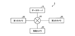
- FIG. 1 is a diagram showing an example of the configuration of the system of the embodiment.
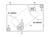
- FIG. 2 is a plan view of a store to which the system of the embodiment is applied.
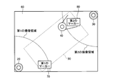
- FIG. 3 is a plan view of a store to which the system of the embodiment is applied.
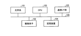
- FIG. 4 is a diagram illustrating an example of a basic hardware configuration of the first camera, the second camera, and the moving camera according to the embodiment.
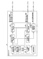
- FIG. 5 is a diagram showing an example of functions of the first camera of the embodiment.
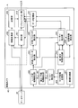
- FIG. 6 is a diagram illustrating an example of functions of the second camera of the embodiment.
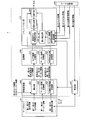
- FIG. 7 is a diagram illustrating an example of functions of the mobile camera according to the embodiment.
- FIG. 8 is a diagram showing a detailed example of functions of the mobile camera of the embodiment.
- FIG. 1 is a diagram showing an example of the configuration of the system of the embodiment.
- FIG. 2 is a plan view of a store to which the system of the embodiment is applied.
- FIG. 3 is a plan view
- FIG. 9 is a diagram illustrating an example of functions of the calculation unit according to the embodiment.
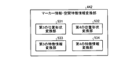
- FIG. 10 is a diagram illustrating an example of functions of the marker information conversion unit according to the embodiment.
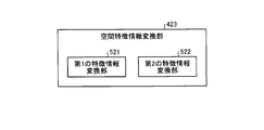
- FIG. 11 is a diagram illustrating an example of functions of the spatial feature information conversion unit according to the embodiment.
- FIG. 12 is a diagram showing an example of functions of the marker information/spatial feature information conversion unit of the embodiment.
- FIG. 13 is a flowchart showing an operation example of the mobile camera of the embodiment.
- FIG. 14 is a diagram showing an example of the configuration of a system of the modified example.
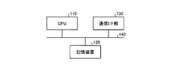
- FIG. 15 is a diagram illustrating an example of the hardware configuration of the server of the modified example.
- FIG. 16 is a diagram illustrating an example of functions of the server of the modification.
- FIG. 1 is a diagram showing an example of the configuration of the system 1 of this embodiment.
- the system 1 of the present embodiment includes a data server 10, a first camera 20, a second camera 30, and a moving camera 40.
- the first camera 20 and the second camera 30 are cameras that can be installed at arbitrary positions and orientations.
- the data server 10 is communicably connected to each of the first camera 20, the second camera 30, and the mobile camera 40 via a network 50 such as the Internet.
- FIG. 2 is a plan view of a place to which the system 1 of this embodiment is applied, for example, a store.
- the first marker 70 and the second marker 80 having different patterns are installed on the floor (floor surface) 60 of the store.
- each of the first marker 70 and the second marker 80 is a flat plate-shaped member having an 8 ⁇ 8 rectangular matrix pattern.
- the first marker 70 and the second marker 80 may be simply referred to as “markers”.
- the first marker 70 is an example of a “first subject” included in the image captured by the first camera 20, and has a first pattern corresponding to the first identification information.
- the first identification information may be an ID indicating “1”
- the first pattern may be a pattern indicating an ID “1”.
- the image captured by the first camera 20 includes the first marker 70.
- the image captured by the first camera 20 may be referred to as the “first image”. That is, the first camera 20 captures the first image including the first marker 70.
- the second marker 80 is an example of the “second subject” included in the image captured by the second camera 30, and has the second pattern corresponding to the second identification information.
- the second identification information may be an ID indicating “2”
- the second pattern may be a pattern indicating an ID “2”.
- the image picked up by the second camera 30 includes the second marker 80.
- the image captured by the second camera 30 may be referred to as a “second image”. That is, the second camera 30 captures the second image including the second marker 80.
- the first camera 20 and the second camera 30 are arranged apart from each other, and are arranged at a position where a common marker cannot be picked up in each picked-up image.
- the first camera 20 and the second camera 30 are arranged at a certain distance or more so that their imaging areas do not overlap.
- the present invention is not limited to this.
- the first camera 20 and the second camera 30 partially overlap with each other in their image capturing areas, they cannot capture a common marker in their respective captured images, or they share a common marker.
- the marker pattern may be arranged at a position where it cannot be recognized.
- the moving camera 40 that takes an image while moving on the floor 60 exists at a position where at least a part of the first imaging area can be taken.
- the moving camera 40 is present at a position where the first marker 70 can be imaged.
- the moving camera 40 can take an image while moving within a range 90 shown in FIG. 2, for example, as shown in FIG. 3, move at least a part of the second image pickup area to a position where an image can be picked up.
- the moving camera 40 is present at a position where the second marker 80 can be imaged.
- the moving camera 40 is a camera capable of capturing an image while moving between a position capable of capturing at least a part of the first imaging region and a position capable of capturing at least a part of the second imaging region. ..
- the moving camera 40 can capture images continuously or multiple times so that a plurality of imaging regions overlap.
- the moving camera 40 is an example of a “third camera”, and captures a first moving image including the first marker 70 and a second moving image including the second marker 80.
- the form of the “third camera” is not limited to the moving camera 40.
- at least a part of the imaging area of the first moving image and at least a part of the imaging area of the second moving image overlap, but the present invention is not limited to this.
- the mobile camera 40 may be, for example, a portable device with a camera (for example, a smartphone, a tablet, a drone, etc.).
- a portable device with a camera for example, a smartphone, a tablet, a drone, etc.
- the case where the mobile camera 40 is a terminal with a camera carried by a user who moves on the floor 60 of the store will be described as an example, but the present invention is not limited to this.
- FIG. 4 is a diagram showing an example of a basic hardware configuration of the first camera 20, the second camera 30, and the moving camera 40. Although the minimum required hardware elements are illustrated in the example of FIG. 4, the hardware elements are not limited to this, and the first camera 20, the second camera 30, and the moving camera 40 may include other hardware elements ( For example, an input device, a display device, etc.) may be provided.
- the hardware elements are not limited to this, and the first camera 20, the second camera 30, and the moving camera 40 may include other hardware elements ( For example, an input device, a display device, etc.) may be provided.
- each of the first camera 20, the second camera 30, and the moving camera 40 includes an optical system 101 such as a lens, an image sensor 102, a CPU (Central Processing Unit) 103, and a storage device. 104 and a communication I/F unit 105 are included.
- the optical system 101, the image sensor 102, the CPU 103, the storage device 104, and the communication I/F unit 105 are connected to each other via a bus 106.
- the image pickup element 102 is an element (element for performing image pickup) that converts an image of an image pickup target formed by the optical system 101 such as a lens into an electric signal.
- the CPU 103 corresponds to an example of a hardware processor.
- the CPU 103 controls the operation of the device (any one of the first camera 20, the second camera 30, and the moving camera 40).
- the CPU 103 realizes various functions of the device by executing the programs stored in the storage device 104. Various functions of each of the first camera 20, the second camera 30, and the moving camera 40 will be described later.
- the storage device 104 stores various data such as programs.
- the storage device 104 includes a ROM (Read Only Memory) that is a non-volatile memory that stores a program, a RAM (Random Access Memory) that is a volatile memory that has a work area of the CPU 103, and the like.
- the communication I/F unit 105 is an interface for connecting to the network 50.
- FIG. 5 is a diagram showing an example of functions of the first camera 20.
- the functions related to the present embodiment are mainly illustrated, but the functions of the first camera 20 are not limited to these.
- the first camera 20 includes an image acquisition unit 201, a point/line segment feature detection unit 202, an internal parameter calculation unit 203, a first marker detection unit 204, an external parameter calculation unit 205, and a spatial feature.
- the detection unit 206, the lens distortion information calculation unit 250, the line segment/arc feature detection unit 251, the marker detection unit 252, and the marker information storage unit 253 are included.
- the image acquisition unit 201 acquires the first image captured by the first camera 20. Specifically, the image acquisition unit 201 acquires the first image captured by the image sensor 102.
- the lens distortion information calculation unit 250 analyzes the first image acquired by the image acquisition unit 201, and detects line segment data (straight line or arc) by the line segment/arc feature detection unit 251.
- the lens distortion information calculation unit 250 calculates the lens distortion information of the first camera 20 based on the line segment data detected by the line segment/arc characteristic detection unit 251.
- the marker detection unit 252 detects the marker based on the line segment data, and the lens distortion information calculation unit 250 calculates the lens distortion information using the shape and size information of the marker detected by the marker detection unit 252. May be.
- the lens distortion model formula is expressed by a higher-order formula using the distortion coefficient in the radial direction of the lens and the distortion coefficient in the circumferential direction, and the lens distortion information is expressed by these coefficients.
- the lens distortion information calculation unit 250 transmits the calculated lens distortion information to the internal parameter calculation unit 203. Further, the lens distortion information calculation unit 250 transmits the lens distortion information and the image from which the distortion of the first image has been removed to the point/line segment feature detection unit 202. Alternatively, when the lens distortion information calculation unit 250 does not generate an image from which distortion has been removed, the lens distortion information and the first image are transmitted to the point/line segment feature detection unit 202. In this example, the lens distortion information is calculated using the first image captured by the first camera 20, but the present invention is not limited to this, and known lens distortion information may be given in advance.
- the point/line segment feature detection unit 202 analyzes the lens distortion information calculated by the lens distortion information calculation unit 250 and the first image or the image from which the distortion of the first image has been removed. More specifically, the point/line segment feature detection unit 202 uses the features of the first marker 70, the peripheral information of the first marker 70, and the spatial features of the entire image (such as a straight line or a plane corresponding to the ground or a wall). Feature data such as (feature) is extracted. Instead of analyzing the image from which the lens distortion is removed, the line segment data detected by the line/arc characteristic detecting unit 251 may be extracted as the characteristic data by correcting the line segment data using the lens distortion information.
- the first marker detection unit 204 based on the feature data detected by the point/line segment feature detection unit 202 and the marker identification information stored in the marker information storage unit 253, sets the first marker in the first image.
- the marker 70 is detected, and first marker information indicating the position and shape of the detected first marker 70 is transmitted to the internal parameter calculation unit 203, the external parameter calculation unit 205, and the data server 10.
- the first marker detection unit 204 recognizes the first identification information corresponding to the first pattern of the detected first marker 70, and recognizes the recognized first identification information. It transmits to the data server 10 together with the first marker information.
- the first marker information includes, for example, the size of one side of the first marker 70, the size of one side of the rectangle that forms the first pattern, information indicating the position of the first marker 70 in the first image, and the like. ..
- the internal parameter calculation unit 203 is based on the lens distortion information received from the lens distortion information calculation unit 250, the known lens focal length of the first camera 20, the first marker information received from the first marker detection unit 204, and the like. Then, the first internal parameter indicating the internal parameter of the first camera 20 is calculated.
- the first internal parameter is a coordinate point of a three-dimensional coordinate system of the camera of the first camera 20 (for example, a three-dimensional coordinate system whose origin is the lens center of the camera), and a first image captured by the first camera 20. It is represented by a matrix that determines the correspondence with the coordinate points of the coordinate system (two-dimensional coordinate system) of one image.
- the internal parameter calculation unit 203 transmits the calculated first internal parameter and the lens distortion information received from the lens distortion information calculation unit 250 to the external parameter calculation unit 205.
- the lens distortion information may be one piece of internal parameter, and hereinafter, when referred to as “first internal parameter”, the lens distortion information is included.
- first internal parameter Various known techniques can be used as the method of calculating the first internal parameter. Further, in this example, the first internal parameter is calculated using the first image captured by the first camera 20, but the present invention is not limited to this, and a known first internal parameter is given in advance. May be
- the external parameter calculation unit 205 based on the first internal parameter received from the internal parameter calculation unit 203 and the first marker information received from the first marker detection unit 204, the external parameter of the first camera 20.
- a first external parameter indicating is calculated.
- the external parameter calculation unit 205 sets the first marker 70 detected by the first marker detection unit 204 as the origin (for example, one of the center or the four corners of the first marker 70).
- the three-dimensional coordinate system on the camera 20 side of No. 1 is set.
- the external parameter calculation unit 205 creates a matrix that determines the correspondence relationship between the set coordinate points of the three-dimensional coordinate system on the first camera 20 side and the coordinate points of the camera of the first camera 20 described above. , As the first external parameter.
- the first external parameter calculated by the external parameter calculation unit 205 is information that can specify the position and orientation of the first camera 20 in the three-dimensional coordinate system on the first camera 20 side. Then, the external parameter calculation unit 205 uses the calculated first external parameter and the first internal parameter received from the internal parameter calculation unit 203 as the first camera information indicating the camera information of the first camera 20. The data is transmitted to the data server 10.
- the spatial feature detection unit 206 receives the first marker based on the first internal parameter and the first external parameter received from the external parameter calculation unit 205, and the feature data received from the point/line segment feature detection unit 202.
- the spatial features around 70 are detected.
- the first spatial characteristic information indicating the peripheral information of the first marker 70 and the spatial characteristic of the entire image is transmitted to the data server 10.
- the information on spatial features may include a set of identifiers such as straight lines, planes, and corners, and position information.
- the data server 10 manages (stores) the first camera information, the first marker information, the first spatial feature information, and the first identification information transmitted from the first camera 20 in association with each other.
- the plurality of functions of the first camera 20 described above are realized by the CPU 103 executing the programs stored in the storage device 104.
- the present invention is not limited to this, and all or some of the plurality of functions of the above-described first camera 20 may be realized by a dedicated hardware circuit.
- FIG. 6 is a diagram showing an example of functions of the second camera 30.
- the functions related to the present embodiment are mainly illustrated, but the functions of the second camera 30 are not limited to these.
- the second camera 30 includes an image acquisition unit 301, a point/line segment feature detection unit 302, an internal parameter calculation unit 303, a second marker detection unit 304, an external parameter calculation unit 305, a spatial feature.
- the detection unit 306, the lens distortion information calculation unit 350, the line segment/arc characteristic detection unit 351, the marker detection unit 352, and the marker information storage unit 353 are included. Since the basic functions are the same as the functions on the first camera 20 side, the functions of the second camera 30 will be described below with appropriate simplification.
- the image acquisition unit 301 acquires the second image captured by the second camera 30. Specifically, the image acquisition unit 301 acquires the second image captured by the image sensor 102.
- the lens distortion information calculation unit 350 analyzes the second image acquired by the image acquisition unit 301, and detects line segment data (straight line or arc) by the line segment/arc feature detection unit 351.
- the lens distortion information calculation unit 350 calculates the lens distortion information of the second camera 30 based on the line segment data detected by the line segment/arc characteristic detection unit 351.
- the marker detection unit 352 detects the marker based on the line segment data, and the lens distortion information calculation unit 350 calculates the lens distortion information using the shape and size information of the marker detected by the marker detection unit 352. May be.
- the lens distortion model formula is expressed by a higher-order formula using the distortion coefficient in the radial direction of the lens and the distortion coefficient in the circumferential direction, and the lens distortion information is expressed by these coefficients.
- the lens distortion information calculation unit 350 transmits the calculated lens distortion information to the internal parameter calculation unit 303.
- the lens distortion information calculation unit 350 also transmits the lens distortion information and the image from which the distortion of the second image has been removed to the point/line segment feature detection unit 302.
- the lens distortion information and the second image are transmitted to the point/line segment feature detection unit 302.
- the lens distortion information is calculated using the second image captured by the second camera 30, but the present invention is not limited to this, and known lens distortion information may be given in advance. Good.
- the point/line segment feature detection unit 302 analyzes the lens distortion information calculated by the lens distortion information calculation unit 350 and the second image or the image from which the distortion of the second image has been removed. More specifically, the point/line segment feature detection unit 302 extracts feature data such as features of the second marker 80, peripheral information of the second marker 80, and spatial features of the entire image. Instead of analyzing the image from which the lens distortion is removed, the line segment data detected by the line segment/arc characteristic detecting unit 351 may be corrected as the feature data by using the lens distortion information.
- the second marker detection unit 304 based on the feature data detected by the point/line segment feature detection unit 302 and the marker identification information stored in the marker information storage unit 353, sets the second marker in the second image.
- the marker 80 is detected, and second marker information indicating the position and shape of the detected second marker 80 is transmitted to the internal parameter calculation unit 303, the external parameter calculation unit 305, and the data server 10.
- the second marker detection unit 304 recognizes the second identification information corresponding to the second pattern of the detected second marker 80, and uses the recognized second identification information as the second marker. It is transmitted to the data server 10 together with the information.
- the second marker information includes, for example, the size of one side of the second marker 80, the size of one side of the rectangle that forms the second pattern, information indicating the position of the second marker 80 in the second image, and the like. ..
- the internal parameter calculation unit 303 is based on the lens distortion information received from the lens distortion information calculation unit 350, the known lens focal length of the second camera 30, the second marker information received from the second marker detection unit 304, and the like. Then, a second internal parameter indicating the internal parameter of the second camera 30 is calculated.
- the second internal parameter is a coordinate point of a three-dimensional coordinate system of the camera of the second camera 30 (for example, a three-dimensional coordinate system having the center of the lens of the camera as an origin) and a second image captured by the second camera 30. It is represented by a matrix that determines the correspondence with the coordinate points of the coordinate system (two-dimensional coordinate system) of the two images.
- the internal parameter calculation unit 303 transmits the calculated second internal parameter and the lens distortion information received from the lens distortion information calculation unit 350 to the external parameter calculation unit 305.
- the lens distortion information may be one of the internal parameters, and hereinafter, when referred to as a "second internal parameter", the lens distortion information is included.
- Various known techniques can be used as the method of calculating the second internal parameter. Further, in this example, the second internal parameter is calculated using the second image captured by the second camera 30, but the present invention is not limited to this, and the known internal parameter may be given in advance. Good.
- the external parameter calculation unit 305 based on the second internal parameter received from the internal parameter calculation unit 303 and the second marker information received from the second marker detection unit 304, the external parameter of the second camera 30.
- a second external parameter indicating is calculated.
- the external parameter calculation unit 305 uses the second marker 80 detected by the second marker detection unit 304 as the origin (for example, the center of the second marker 80 or any one of the four corners) of the second camera 30. Set the side 3D coordinate system.
- the external parameter calculation unit 305 calculates a matrix that determines the correspondence between the set coordinate points of the three-dimensional coordinate system on the side of the second camera 30 and the coordinate points of the three-dimensional coordinate system of the camera of the second camera 30, It is calculated as an external parameter of 2.
- the second external parameter calculated by the external parameter calculation unit 305 is information that can specify the position and orientation of the second camera 30 in the three-dimensional coordinate system on the second camera 30 side. Then, the external parameter calculation unit 305 sets the calculated second external parameter and the second internal parameter received from the internal parameter calculation unit 303 as second camera information indicating the camera information of the second camera 30. The data is transmitted to the data server 10.
- the spatial feature detection unit 306 receives the second marker based on the second internal parameter and the second external parameter received from the external parameter calculation unit 305, and the feature data received from the point/line segment feature detection unit 302. Detect spatial features around 80. Then, the second spatial characteristic information indicating the peripheral information of the second marker 80 and the spatial characteristic of the entire image is transmitted to the data server 10.
- the data server 10 manages (stores) the second camera information, the second marker information, the second spatial feature information, and the second identification information transmitted from the second camera 30 in association with each other.
- the first marker information and the second marker information managed by the data server 10 may be simply referred to as “marker information” when they are not distinguished from each other.
- first identification information and the second identification information managed by the data server 10 are not distinguished from each other, they are simply referred to as “identification information” and the first spatial feature information and the second spatial feature information are distinguished from each other. If not, it may be simply referred to as "spatial feature information”.
- the plurality of functions of the second camera 30 described above are realized by the CPU 103 executing the programs stored in the storage device 104.
- the present invention is not limited to this.
- all or some of the plurality of functions of the second camera 30 described above may be realized by a dedicated hardware circuit.
- FIG. 7 is a diagram showing an example of functions of the mobile camera 40.
- the moving camera 40 includes an image acquisition unit 401, a point/line segment feature detection unit 402, an internal parameter calculation unit 403, a marker detection unit 404, an external parameter calculation unit 405, a spatial feature detection unit 406, and a lens. It has a distortion information calculation unit 450, a line segment/arc feature detection unit 451, a marker detection unit 452, and a marker information storage unit 453.
- the mobile camera 40 has a collation unit 407, an information conversion unit 408, a storage unit 409, a simulation unit 410, and a data storage unit 454.
- the image acquisition unit 401 acquires a moving image captured by the mobile camera 40. More specifically, the image acquisition unit 401 sequentially acquires the third images captured in time series by the image sensor 102 (acquires moving images).
- the lens distortion information calculation unit 450 analyzes the third image acquired by the image acquisition unit 401, and detects line segment data (straight line or arc) by the line segment/arc feature detection unit 451.
- the lens distortion information calculation unit 450 calculates the lens distortion information of the moving camera 40 based on the line segment data detected by the line segment/circular arc feature detection unit 451.
- the marker detection unit 452 detects the marker based on the line segment data, and the lens distortion information calculation unit 450 calculates the lens distortion information using the shape and size information of the marker detected by the marker detection unit 452. May be.
- the lens distortion model formula is expressed by a higher-order formula using the distortion coefficient in the radial direction of the lens and the distortion coefficient in the circumferential direction, and the lens distortion information is expressed by these coefficients.
- the lens distortion information calculation unit 450 transmits the calculated lens distortion information to the internal parameter calculation unit 403. Further, the lens distortion information calculation unit 450 transmits the lens distortion information and the image from which the distortion of the third image is removed to the point/line segment feature detection unit 402. Alternatively, when the lens distortion information calculation unit 450 does not generate an image from which distortion has been removed, the lens distortion information and the third image are transmitted to the point/line segment feature detection unit 402. Further, in this example, the lens distortion information is calculated using the image of the moving image (third image) captured by the moving camera 40, but the present invention is not limited to this, and the known lens distortion information is given in advance. May be
- the point/line segment feature detection unit 402 analyzes the lens distortion information calculated by the lens distortion information calculation unit 450 and the third image or the image from which the distortion of the third image has been removed. More specifically, the point/line segment feature detection unit 402 detects the moving image such as the marker feature, the marker peripheral information, and the spatial feature of the entire image (straight line or plane feature corresponding to the ground or wall). Extract included feature data. Instead of analyzing the image from which the lens distortion is removed, the line segment data detected by the line/arc characteristic detecting unit 451 may be corrected as the characteristic data by using the lens distortion information.
- the marker detection unit 404 based on the feature data detected by the point/line segment feature detection unit 402 and the marker identification information stored in the marker information storage unit 453, the marker in the moving image (first marker in this example).
- the marker 70 or the second marker 80) is detected.
- the marker detection unit 404 transmits the third marker information indicating the position and shape of the detected marker to the internal parameter calculation unit 403 and the external parameter calculation unit 405.
- the third marker information includes, for example, the size of one side of the marker, the size of one side of the rectangle forming the pattern of the marker, information indicating the position of the marker in the moving image, and the like.
- the marker detection unit 404 recognizes the identification information corresponding to the pattern of the detected marker, and combines the recognized third identification information with the third marker information, the external parameter calculation unit 405, and the data storage. It is transmitted to the section 454.
- the marker detection unit 404 can also perform marker detection and third identification information recognition using images of a plurality of frames.
- the internal parameter calculation unit 403 is based on the lens distortion information received from the lens distortion information calculation unit 450, the known lens focal length of the moving camera 40, the lens distortion coefficient, the third marker information received from the marker detection unit 404, and the like. Then, a third internal parameter indicating the internal parameter of the mobile camera 40 is calculated.
- the third internal parameter is a coordinate point of a three-dimensional coordinate system of the camera of the moving camera 40 (for example, a three-dimensional coordinate system whose origin is the lens center of the camera) and an image of a moving image taken by the moving camera 40 ( The third image) is represented by a matrix that determines the correspondence with the coordinate points of the coordinate system (two-dimensional coordinate system).
- the internal parameter calculation unit 403 transmits the calculated third internal parameter and the lens distortion information received from the lens distortion information calculation unit 450 to the external parameter calculation unit 405.
- the lens distortion information may be one piece of internal parameter, and hereinafter, when referred to as “third internal parameter”, the lens distortion information is included.
- Various known techniques can be used as the method of calculating the internal parameter. Further, in this example, the internal parameter is calculated using the image of the moving image (third image) captured by the moving camera 40, but the present invention is not limited to this, and the known internal parameter is given in advance. May be.
- the external parameter calculation unit 405 indicates the external parameter of the mobile camera 40 based on the third internal parameter received from the internal parameter calculation unit 403 and the third marker information received from the marker detection unit 404. Calculate external parameters.
- the external parameter calculation unit 405 uses the first marker (the first marker 70 in this example) detected by the marker detection unit 404 as the origin (for example, the center or the four corners of the first marker 70).
- the three-dimensional coordinate system on the side of the moving camera 40 is set.
- the external parameter calculation unit 405 creates a matrix that determines the correspondence between the set coordinate points of the three-dimensional coordinate system on the side of the moving camera 40 and the coordinate points of the three-dimensional coordinate system of the camera of the moving camera 40 described above. Calculate as an external parameter.
- the third external parameter calculated by the external parameter calculation unit 405 is information that can specify the position and orientation of the moving camera 40 in the three-dimensional coordinate system on the moving camera 40 side.
- the external parameter calculation unit 405 does not change the origin even when the second and subsequent markers (the second marker 80 in this example) are detected, and the moving camera 40 sequentially captures images.
- a third external parameter is calculated based on the moving image (the amount of movement and acceleration of the subject obtained from the moving image can also be used).
- the external parameter calculation unit 405 calculates the third external parameter of the mobile camera 40 each time it receives the third marker information from the marker detection unit 404 (that is, each time a new marker is detected). Then, the external parameter calculation unit 405 stores the calculated third external parameter and the third internal parameter received from the internal parameter calculation unit 403 as the third camera information indicating the camera information of the mobile camera 40. It is transmitted to the storage unit 454. In addition, the external parameter calculation unit 405 transmits the third marker information received from the marker detection unit 404 to the data storage unit 454. That is, in this example, every time the marker detection unit 404 detects a marker, the third camera information and the third marker information corresponding to the marker are transmitted to the data storage unit 454.
- the spatial feature detection unit 406 detects the vicinity of the marker based on the third internal parameter and the third external parameter received from the external parameter calculation unit 405 and the feature data received from the point/line segment feature detection unit 402. Detect spatial features. Then, the third spatial feature information indicating the peripheral information of the marker and the spatial feature of the entire image is transmitted to the data storage unit 454.
- the third spatial feature information may include a set of identifiers such as a straight line, a plane, and a corner, and position information.
- the data storage unit 454 stores the third camera information of the mobile camera 40, the third marker information, the third spatial feature information, and the third identification information.
- the collation unit 407 reads the set of the third marker information and the third identification information from the data storage unit 454, and determines whether the data server 10 has the identification information that matches the third identification information included in the set. Check if The collating unit 407 sets the reference coordinate system when the confirmed identification information exists in the data server 10. Specifically, the first marker 70 detected from the first image captured by the first camera 20, or the second marker 80 detected from the second image captured by the second camera 30, and the moving camera 40. The marker detected from the captured moving image is associated with the same marker, the reference coordinates are set, and the identification information of the marker set in the reference coordinate system is transmitted to the data server 10. In this example, the reference coordinate system is based on the first marker 70.
- the third identification information set as the reference coordinate includes the identification information set in the reference coordinate system and is transmitted to the information conversion unit 408 and the simulation unit 410.
- the matching unit 407 causes the matching unit 407 to associate the identification information with the first or second camera information, the first or second marker information, and the first or second camera information.
- the data server 10 is instructed to transmit the spatial feature information of No. 2 to the information conversion unit 408. Upon receiving this instruction, the data server 10 transmits the first or second camera information, the first or second marker information, and the first or second spatial feature information to the information conversion unit 408.
- the information conversion unit 408 receives the first or second camera information, the first or second marker information, and the first or second spatial feature information from the data server 10, the information conversion unit 408 receives the first or second camera information.
- the first or second marker information and the first or second spatial feature information are converted according to the above-mentioned reference coordinate system. That is, the information conversion unit 408 captures the moving image captured by the moving camera 40 with the first marker 70 included in the first image captured by the first camera 20 or the second camera 30 capturing the captured image.
- the second marker 80 included in the captured second image is detected, the first camera information or the like of the first camera 20 or the second camera information or the like of the second camera 30 is used as reference coordinates. Convert according to the system. The specific content of the information conversion unit 408 will be described later.
- the information converted by the information conversion unit 408 (converted information) is stored in the storage unit 409.
- the simulation unit 410 reads the converted information of each of the first camera 20 and the second camera 30 stored in the storage unit 409, reads the information from the data storage unit 454 on the mobile camera 40 side, and converts the information. The difference is detected by comparison. More specific functions of the simulation unit 410 will be described later.
- FIG. 8 is a functional block diagram for explaining more specific contents of the information conversion unit 408, the storage unit 409, and the simulation unit 410.
- the portion A shown in FIG. 8 corresponds to the portion A shown in FIG. 7.
- the collation unit 407 associates the first camera with the identification information.
- a data server so as to transmit information of the 20 or second camera 30 (first or second camera information, first or second marker information, first or second spatial feature information) to the information conversion unit 408.
- the data server 10 that has received this instruction transmits the information of the first camera 20 or the second camera 30 to the information conversion unit 408.
- the information conversion unit 408 receives the third identification information including the identification information set in the reference coordinate system from the collation unit 407.
- the first marker 70 included in the first image captured by the first camera 20 or the second image captured by the second camera 30 is input to the information conversion unit 408, and the information conversion unit 408 performs conversion.
- the first marker 70 is detected from the moving image of the moving camera 40
- the first camera information of the first camera 20 the first marker information, and the first spatial feature information are converted into information. It is input to the unit 408.
- the second marker 80 is detected from the moving image of the moving camera 40 that has moved to the position where the second imaging region can be imaged
- the second camera information of the second camera 30 and the second marker information are detected.
- the second spatial feature information are input to the information conversion unit 408.
- the information conversion unit 408 includes a calculation unit 421, a marker information conversion unit 422, and a spatial feature information conversion unit 423.
- the calculation unit 421 converts the first camera information of the first camera 20 or the second camera information of the second camera 30 in accordance with the above-described reference coordinate system, and the first or second reference coordinate system camera. Output information.
- FIG. 9 is a diagram illustrating an example of functions of the calculation unit 421. As shown in FIG. 9, for example, the calculation unit 421 has a first calculation unit 501 and a second calculation unit 502. Note that the example of FIG. 9 mainly illustrates the functions related to the present embodiment, but the functions of the calculation unit 421 are not limited to these.
- the first calculation unit 501 includes a first image including the first marker 70 captured by the first camera 20 and a first moving image including the first marker 70 captured by the moving camera 40. Based on the first reference coordinate system camera information indicating the position of the first camera 20. More specifically, when the first marker 70 is detected from the moving image captured by the moving camera 40, the first calculator 501 uses the first camera information as a reference based on the first image. It is converted into the first reference coordinate system camera information indicating the position of the first camera 20 in the coordinate system. In this example, the moving image including the first marker 70 captured by the moving camera 40 corresponds to the “first moving image”, but the present invention is not limited to this.
- the first reference coordinate system camera information determines the correspondence between the coordinate points of the reference coordinate system and the coordinate points of the three-dimensional coordinate system of the camera of the first camera 20.
- the first external parameter which may be referred to as a “converted first external parameter” hereinafter
- the first reference coordinate system camera information is information indicating a correspondence relationship between the reference coordinate system common to the first camera 20, the second camera 30, and the moving camera 40 and the coordinate system of the first camera 20. If Hereinafter, a specific method of calculating the first reference coordinate system camera information will be described.
- the first calculator 501 of the present embodiment receives the information of the first camera 20 from the data server 10, that is, the first marker 70 is detected from the moving image captured by the moving camera 40. , The first external parameter is converted into the first reference coordinate system camera information. The first calculator 501 calculates the three-dimensional position (x, y, z) and the orientation (rotation) of the first marker 70 in the reference coordinate system, the first internal parameter of the first camera 20, and the first internal parameter. Based on the position and orientation of the first marker 70 in the image, the first external parameter of the first camera 20 that matches the reference coordinate system is calculated as the first reference coordinate system camera information.
- the first internal parameter of the first camera 20 is included in the first camera information of the first camera 20 received from the data server 10.
- the information indicating the position of the first marker 70 in the first image is included in the first marker information received from the data server 10.
- the first camera information and the first marker information of the first camera 20 received from the data server 10 are obtained based on the first image.
- the position of the first marker 70 in the reference coordinate system is set to the origin of the reference coordinate system, so that the position can be specified without using the moving image of the moving camera 40. Therefore, it can be considered that the first calculation unit 501 calculates the first reference coordinate system camera information indicating the position of the first camera 20 in the reference coordinate system based on the first image.
- the first reference coordinate system camera information is an example of “first camera position information”, but is not limited to this.
- the first reference coordinate system camera information is the converted first external parameter of the first camera 20, but the present invention is not limited to this.
- the second calculation unit 502 includes a second image including the second marker 80 captured by the second camera 30 that is arranged apart from the first camera 20, and a second image captured by the moving camera 40.
- the second reference coordinate system camera information indicating the position of the second camera 30 is calculated based on the second moving image including the two markers 80. More specifically, when the second marker 80 is detected from the moving image captured by the moving camera 40, the second calculating unit 502 determines the second image and the moving image captured by the moving camera 40.
- the second camera information is converted into the second reference coordinate system camera information indicating the position of the second camera 30 in the reference coordinate system based on In this example, the moving image including the second marker 80 captured by the moving camera 40 corresponds to the “second moving image”, but the present invention is not limited to this.
- the second reference coordinate system camera information is the second camera 30 that determines the correspondence between the coordinate points of the reference coordinate system and the coordinate points of the three-dimensional coordinate system of the camera of the second camera 30.
- Second external parameter (the second external parameter matched to the reference coordinate system, hereinafter may be referred to as “converted second external parameter”), but is not limited thereto.
- the second reference coordinate system camera information may be information indicating the correspondence relationship between the reference coordinate system and the coordinate system of the second camera 30.
- a specific method of calculating the second reference coordinate system camera information will be described.
- the second calculation unit 502 of the present embodiment receives the information of the second camera 30 from the data server 10, that is, the second marker 80 is detected from the moving image captured by the moving camera 40. , The second external parameter is converted into second reference coordinate system camera information. As described above, when the second marker 80 is detected, the third camera information and the third marker information corresponding to the second marker 80 are transmitted from the data storage unit 454 to the information conversion unit 408. .. The second calculation unit 502, based on the third camera information and the third marker information corresponding to the second marker 80 received from the data storage unit 454, the reference coordinate system (the first marker 70 in this example). The three-dimensional position (x, y, z) and the orientation (rotation) of the second marker 80 at the origin is specified.
- the second calculation unit 502 determines the position and orientation of the second marker 80 indicated by the third marker information, the third external parameter included in the third camera information, and the third internal parameter.
- the position and orientation of the second marker 80 in the reference coordinate system are specified based on the parameters and.
- the third external parameter included in the third camera information is, for example, the movement amount and the rotation amount of the moving camera 40, that is, the orientation of the moving camera 40 when the first marker 70 is detected, and the second marker 80 when the second marker 80 is detected. Represents the difference from the direction of the moving camera 40.
- the third camera information and the third marker information corresponding to the second marker 80 are obtained based on the moving image captured by the moving camera 40. Therefore, it can be considered that the second calculator 502 specifies the position and orientation of the second marker 80 in the reference coordinate system based on the moving image captured by the moving camera 40.
- the second calculation unit 502 calculates the position and orientation of the second marker 80 in the reference coordinate system, the second internal parameter of the second camera 30, and the second marker 80 in the second image. Based on the position and the orientation, the second external parameter of the second camera 30 that matches the reference coordinate system is calculated as the second reference coordinate system camera information.
- the second internal parameter of the second camera 30 is included in the second camera information received from the data server 10.
- the information indicating the position of the second marker 80 in the second image is included in the second marker information received from the data server 10.
- the second camera information of the second camera 30 and the second marker information are obtained based on the second image.
- the second calculation unit 502 of the present exemplary embodiment based on the second image and the moving image captured by the moving camera 40, is the second position indicating the position of the second camera 30 in the reference coordinate system. It can be considered that the reference coordinate system camera information is calculated.
- the second reference coordinate system camera information is an example of “second camera position information”, but is not limited to this.
- the second reference coordinate system camera information is the converted second external parameter of the second camera 30, but it is not limited to this.
- the first reference coordinate system camera information and the second reference coordinate system camera information calculated by the calculation unit 421 as described above are stored in the storage unit 409. In the following description, when the first reference coordinate system camera information and the second reference coordinate system camera information are not distinguished, they may be referred to as “reference coordinate system camera information”.
- the marker information conversion unit 422 is an example of a “first conversion unit”, and converts the information on the position and shape of the first marker 70 included in the first image according to the reference coordinate system to convert the first information.
- the converted information is output, or the information on the position and shape of the second marker 80 included in the second image is converted according to the reference coordinate system and the second converted information is output.
- the marker information conversion unit 422 converts the first marker information or the second marker information according to the above-mentioned reference coordinate system.
- the marker information conversion unit 422 includes the first reference coordinate system camera information or the second reference coordinate system camera information calculated by the calculation unit 421, and the first internal parameter of the first camera 20 or the second camera.
- the above conversion can be performed.
- the first marker information converted by the marker information conversion unit 422 is referred to as “converted first marker information”
- the second marker information converted by the marker information conversion unit 422 is referred to as “converted”. It may be referred to as "already used second marker information”. When the two are not distinguished, they are referred to as "converted marker information”.
- the converted marker information is stored in the storage unit 409.
- the converted first marker information corresponds to the above-mentioned "first converted information”
- the converted second marker information corresponds to the above-mentioned "second converted information”.
- FIG. 10 is a diagram showing an example of functions of the marker information conversion unit 422.
- the marker information conversion unit 422 includes a first position shape conversion unit 511 and a second position shape conversion unit 512.
- the function of the marker information conversion unit 422 is not limited to these.
- the first position/shape conversion unit 511 converts the position and shape information of the first marker 70 in the first image into the above-described position and shape information in the reference coordinate system.
- the first position/shape conversion unit 511 uses the above-described first reference coordinate system camera information (in this example, the converted first external parameter) and the first camera 20 of the first camera 20 acquired from the data server 10.
- the first marker information acquired from the data server 10 is converted using the internal parameter of 1 according to the reference coordinate system.
- the first marker information converted according to the reference coordinate system will be referred to as “converted first marker information”.
- the second position/shape conversion unit 512 converts the position and shape information of the second marker 80 in the second image into the above-described position and shape information in the reference coordinate system.
- the second position/shape conversion unit 512 may use the above-described second reference coordinate system camera information (in this example, the converted second external parameter) and the second camera 30 of the second camera 30 acquired from the data server 10.
- the second marker information acquired from the data server 10 is converted using the internal parameters of 2 according to the reference coordinate system.
- the second marker information converted according to the reference coordinate system will be referred to as "converted second marker information".
- the spatial feature information conversion unit 423 converts the first or second spatial feature information according to the above-mentioned reference coordinate system.
- the spatial feature information conversion unit 423 uses the first or second reference coordinate system camera information calculated by the calculation unit 421, the known first internal parameter of the first camera 20, or the second internal parameter of the second camera 30.
- the above conversion can be performed using two internal parameters.
- the first spatial feature information converted by the spatial feature information conversion unit 423 is referred to as “converted first spatial feature information”
- the converted second spatial feature information is referred to as “converted It may be referred to as "second spatial feature information”.
- the converted spatial feature information is stored in the storage unit 409.
- FIG. 11 is a diagram showing an example of functions of the spatial feature information conversion unit 423.
- the spatial feature information conversion unit 423 includes a first feature information conversion unit 521 and a second feature information conversion unit 522.
- the function of the spatial feature information conversion unit 423 is not limited to these.
- the first feature information conversion unit 521 converts the first spatial feature information described above according to the reference coordinate system described above.
- the first feature information conversion unit 521 performs conversion such as scale, parallel movement, and rotational movement.
- the first feature information conversion unit 521 uses the above-described first reference coordinate system camera information (in this example, the converted first external parameter) and the first camera 20 of the first camera 20 acquired from the data server 10.
- the first spatial feature information acquired from the data server 10 is converted using the internal parameter of 1 according to the reference coordinate system.
- the second feature information conversion unit 522 converts the second spatial feature information described above according to the reference coordinate system described above.
- the second feature information conversion unit 522 uses the above-described second reference coordinate system camera information (in this example, the converted second external parameter) and the second camera 30 of the second camera 30 acquired from the data server 10.
- the second spatial characteristic information acquired from the data server 10 is converted according to the reference coordinate system by using the internal parameters of 2.
- the storage unit 409 includes a camera information storage unit 431, a marker information storage unit 432, and a spatial feature information storage unit 433.
- the camera information storage unit 431 is a storage area for storing the reference coordinate system camera information calculated by the calculation unit 421.
- the marker information storage unit 432 is a storage area for storing the converted marker information converted by the marker information conversion unit 422.
- the spatial feature information storage unit 433 is a storage area for storing the converted spatial feature information converted by the spatial feature information conversion unit 423.
- the simulation unit 410 includes a converted information acquisition unit 441, a marker information/spatial feature information conversion unit 442, a difference detection unit 443, a recalculation unit 444, and a correction unit 445.
- the converted information acquisition unit 441 acquires converted information (including reference coordinate system camera information, converted marker information, and converted spatial feature information) from the storage unit 409.
- the converted information acquisition unit 441 converts each of the first camera 20 and the second camera 30 at the timing when the converted information of each of the first camera 20 and the second camera 30 is acquired.
- the completed information is transmitted to the difference detection unit 443.
- the marker information/spatial characteristic information conversion unit 442 receives the third identification information including the identification information set in the reference coordinate system from the matching unit 407, and converts the information on the side of the mobile camera 40 according to the reference coordinate system. And transmits it to the difference detection unit 443.
- the marker information/spatial characteristic information conversion unit 442 has a function of converting the third marker information of the moving camera 40 according to the above-mentioned reference coordinate system.
- the marker information/spatial feature information conversion unit 442 is an example of a “second conversion unit”, and uses the position and shape information of the first marker 70 included in the moving image captured by the moving camera 40 as a reference coordinate system. It is also converted and the third converted information is output.
- the marker information/spatial feature information conversion unit 442 converts the position and shape information of the second marker 80 included in the moving image captured by the moving camera 40 according to the reference coordinate system to perform the fourth conversion. Output the completed information. More specific contents will be described later. Further, the marker information/spatial characteristic information conversion unit 442 also has a function of converting the third spatial characteristic information of the moving camera 40 according to the above-mentioned reference coordinate system.
- FIG. 12 is a diagram showing an example of functions of the marker information/spatial feature information conversion unit 442.
- the marker information/spatial feature information conversion unit 442 includes a third position shape conversion unit 531, a fourth position shape conversion unit 532, a third feature information conversion unit 533, and 4 feature information conversion unit 534.
- the functions of the marker information/spatial feature information conversion unit 442 are not limited to these.
- the marker information/spatial characteristic information conversion unit 442 has a function of constructing a space of the above-mentioned reference coordinate system (for example, constructing a 3D model showing a three-dimensional point group) based on a moving image captured by the moving camera 40. You may have.
- the third position/shape conversion unit 531 converts the position and shape information of the first marker 70 in the moving image captured by the moving camera 40 into the above-described position and shape information in the reference coordinate system.
- the marker information/spatial feature information conversion unit 442 performs the above conversion by using the third internal parameter and the third external parameter of the moving camera 40 when the first marker 70 is detected by the moving camera 40. be able to.
- the position of the first marker 70 in the reference coordinate system is set to the origin of the reference coordinate system, the position and shape of the first marker 70 in the moving image captured by the moving camera 40 can be changed. Information can also be used.
- the position and shape information of the first marker 70 converted by the third position/shape converting unit 531 corresponds to the above-mentioned “third converted information”, but the information is not limited to this. Not a thing.
- the fourth position/shape conversion unit 532 converts the position and shape information of the second marker 80 in the moving image captured by the moving camera 40 into the position and shape information in the reference coordinate system described above.
- the marker information/spatial characteristic information conversion unit 442 performs the above conversion using the third internal parameter and the third external parameter of the moving camera 40 when the second marker 80 is detected by the moving camera 40. be able to.
- the position and shape information of the second marker 80 converted by the fourth position/shape conversion unit 532 corresponds to the above-mentioned “fourth converted information”, but the information is not limited to this. Not a thing.
- the third characteristic information conversion unit 533 converts the characteristic information of the peripheral information of the first marker 70 in the moving image captured by the moving camera 40 into the characteristic information in the reference coordinate system described above.
- the marker information/spatial feature information conversion unit 442 performs the above conversion by using the third internal parameter and the third external parameter of the moving camera 40 when the first marker 70 is detected by the moving camera 40. be able to.
- the characteristics of the peripheral information of the first marker 70 in the moving image captured by the moving camera 40. Information can also be used.
- the fourth characteristic information conversion unit 534 converts the characteristic information of the peripheral information of the second marker 80 in the moving image captured by the moving camera 40 into the characteristic information in the reference coordinate system described above.
- the marker information/spatial characteristic information conversion unit 442 performs the above conversion using the third internal parameter and the third external parameter of the moving camera 40 when the second marker 80 is detected by the moving camera 40. be able to.
- the difference detection unit 443 detects a difference between the converted marker information on the first camera 20 and second camera 30 side and the converted marker information on the moving camera 40 side.
- the difference detection unit 443 detects the position and shape information of the first marker 70 based on the first image and the position and shape of the first marker 70 based on the moving image captured by the moving camera 40.
- the first difference indicating the difference from the information is detected.
- the difference detection unit 443 stores information on the position and shape of the second marker 80 based on the second image, and information on the position and shape of the second marker 80 based on the moving image captured by the moving camera 40.
- the second difference indicating the difference between the two is detected. More specifically, it is as follows.
- the difference detection unit 443 includes information on the position and shape of the first marker 70 converted by the above-described first position/shape conversion unit 511 (corresponding to “first converted information” in this example) and the above-mentioned information.
- the first difference indicating the difference from the position and shape information of the first marker 70 converted by the third position shape conversion unit 531 (corresponding to “third converted information” in this example) is detected. .. That is, the difference detection unit 443 detects the first difference by comparing the above-mentioned first converted information and the above-mentioned third converted information.
- the information on the position and shape of the first marker 70 converted by the first position shape conversion unit 511 is based on the position and shape of the first marker 70 in the first image in the reference coordinate system. It is converted into position and shape information.
- the position and shape information of the first marker 70 converted by the third position shape conversion unit 531 is the position and shape of the first marker 70 in the moving image captured by the moving camera 40 in the reference coordinate system. And the shape information.
- the difference detection unit 443 stores information on the position and shape of the second marker 80 converted by the above-described second position shape conversion unit 512 (corresponding to “second converted information” in this example), A second difference indicating a difference from the position and shape information of the second marker 80 converted by the above-mentioned fourth position shape conversion unit 532 (corresponding to “fourth converted information” in this example) To detect. That is, the difference detection unit 443 detects the second difference by comparing the above-mentioned second converted information with the above-mentioned fourth converted information. As described above, the information on the position and shape of the second marker 80 converted by the second position/shape converting unit 512 is the position and shape of the second marker 80 in the second image in the reference coordinate system.
- the position and shape information of the second marker 80 converted by the fourth position shape conversion unit 532 is the reference coordinates. It is converted into the position and shape in the system.
- the difference detection unit 443 may be configured to detect the first difference and the second difference by converting the viewpoint of the marker viewed from the fixed camera using the third external parameter of the moving camera 40.
- the difference detection unit 443 indicates the difference between the spatial feature information converted by the first feature information conversion unit 521 and the spatial feature information converted by the third feature information conversion unit 533.
- the difference of 3 is detected. That is, the difference detection unit 443 performs detailed matching including spatial feature information (not only complete matching, but partial matching or approximation-based matching may be performed) to detect the above-described third difference.
- the spatial feature information converted by the first feature information conversion unit 521 is the feature information of the peripheral information of the first marker 70 in the first image converted to the feature information in the reference coordinate system described above. It has been converted.
- the spatial feature information converted by the third feature information conversion unit 533 is the feature information of the peripheral information of the first marker 70 in the moving image captured by the moving camera 40, which is converted into the feature information in the reference coordinate system. It has been converted.
- the difference detection unit 443 indicates the difference between the spatial feature information converted by the second feature information conversion unit 522 described above and the spatial feature information converted by the fourth feature information conversion unit 534 described above.
- the fourth difference is detected.
- the spatial feature information converted by the second feature information conversion unit 522 is the feature information of the peripheral information of the second marker 80 in the second image converted to the feature information in the reference coordinate system. It is a thing.
- the spatial feature information converted by the fourth feature information conversion unit 534 converts the feature information of the peripheral information of the second marker 80 in the moving image captured by the moving camera 40 into the spatial feature information in the reference coordinate system. It was done.
- the first to fourth differences detected by the difference detection unit 443 as described above are input to the correction unit 445.
- the difference detection unit 443 transmits the respective values of the first difference and the third difference or the second difference and the fourth difference to the correction unit 445.
- the present invention is not limited to this, and only the first difference or the second difference may be detected and transmitted to the correction unit 445.
- the correction unit 445 corrects the above-described first reference coordinate system camera information (in this example, the converted first external parameter) based on the first difference, and based on the second difference, the above-mentioned first reference coordinate system camera information.
- the second reference coordinate system camera information (in this example, the converted second external parameter) is corrected.
- the correction unit 445 corrects the above-described first reference coordinate system camera information (in this example, the converted first external parameter) based on the first difference and the third difference, and the second The second reference coordinate system camera information (in this example, the converted second external parameter) may be corrected based on the difference and the fourth difference. More specifically, the correction unit 445 uses the above-described first reference coordinate so that each of the first difference, the third difference, the second difference, and the fourth difference is equal to or less than the allowable value. The system camera information and the second reference coordinate system camera information are corrected. The permissible value can be arbitrarily changed according to design conditions and the like.
- the corrected first reference coordinate system camera information and the second reference coordinate system camera information are It is input to the calculation unit 444.
- the recalculation unit 444 acquires the corrected first reference coordinate system camera information and the second reference coordinate system camera information from the correction unit 445
- the converted marker information and the converted spatial feature are acquired.
- the information is acquired from the converted information acquisition unit 441.
- the recalculation unit 444 uses the corrected first reference coordinate system camera information and the second reference coordinate system camera information acquired from the correction unit 445 to obtain the converted information acquired from the converted information acquisition unit 441. Recalculate marker information and transformed spatial feature information.
- the recalculation unit 444 inputs the recalculated marker information and spatial feature information to the difference detection unit 443. Then, the difference detection unit 443 detects again the above-mentioned first difference, third difference, and second difference and fourth difference, and inputs them to the correction unit 445.
- the correction unit 445 determines whether the first reference coordinate system camera at that time is present.
- the information and the second reference coordinate system camera information are output, and at the same time, the converted spatial feature information (spatial feature information converted according to the reference coordinate system) is output.
- the output destinations of the first reference coordinate system camera information, the second reference coordinate system camera information, and the converted spatial feature information from the correction unit 445 are an information processing device, an edge server (in-store server), and a cloud server.
- a server for providing a final service may be used.
- the server can generate service information based on processing using these pieces of information and provide the service information to the user (for example, output to the terminal (the mobile camera 40) owned by the user).
- various processing in the recognition processing using the image of the first camera 20 or the second camera 30 after position correction is assumed.
- a process of determining that a person or an object cannot move due to the presence of an obstacle with a height a process of determining an overlap of a person or an object, data such as a movement route, and the like are stored in the first camera 20.
- a process of superimposing the image on the second camera 30 and a process of drawing a 3D space are assumed.
- the above processing is not limited to the above examples.
- the plurality of functions of the mobile camera 40 described above are realized by the CPU 103 executing a program stored in the storage device 104.
- the present invention is not limited to this.
- all or some of the plurality of functions of the mobile camera 40 described above may be realized by a dedicated hardware circuit.
- the marker information storage unit 253, the marker information storage unit 353, the marker information storage unit 453, the data storage unit 454, and the storage unit 409 may be, for example, the storage device 104 or the like.
- the moving camera 40 functions as a “camera information calculation device” that calculates the above-described first reference coordinate system camera information and second reference coordinate system camera information.
- FIG. 13 is a flowchart showing an operation example of the mobile camera 40 of this embodiment. Since the specific contents of each step are as described above, the description will be omitted as appropriate. Note that the order of each step can be arbitrarily changed and is not limited to the example of FIG.
- the marker detection unit 404 detects the first pattern (first marker 70) (step S1)
- the marker information/spatial feature information conversion unit 442 in the simulation unit 410 is located on the moving camera 40 side.
- the information is converted (step S2).
- the marker information/spatial feature information conversion unit 442 converts the position and shape information of the first marker 70 detected by the marker detection unit 404 according to the reference coordinate system.
- the marker information/spatial characteristic information conversion unit 442 converts the characteristic information of the peripheral information of the first marker 70 detected by the spatial characteristic detection unit 406 according to the reference coordinate system.
- the specific content is as described above.
- the matching unit 407 matches whether or not the first identification information corresponding to the first pattern (first marker 70) detected by the marker detection unit 404 exists in the data server 10 (step S3). ).
- the description will be continued assuming that the first identification information exists in the data server 10.
- the information conversion unit 408 acquires the first camera information, the first marker information, and the first spatial feature information from the data server 10 (step S4).
- the information conversion unit 408 converts the information (first camera information, first marker information, and first spatial feature information) acquired in step S4 according to the above-described reference coordinate system (step S5).
- the specific content is as described above.
- the marker information/spatial feature information converting unit 442. Converts the information on the mobile camera 40 side (step S7).
- the marker information/spatial feature information conversion unit 442 converts the position and shape information of the second marker 80 detected by the marker detection unit 404 according to the reference coordinate system.
- the feature information of the peripheral information of the second marker 80 detected by the spatial feature detection unit 406 is converted according to the reference coordinate system. The specific content is as described above.
- the matching unit 407 matches whether or not the second identification information corresponding to the second pattern (second marker 80) detected by the marker detection unit 404 exists in the data server 10 (step S8). ).
- the description will be continued assuming that the second identification information exists in the data server 10.
- the information conversion unit 408 acquires the second camera information, the second marker information, and the second spatial feature information from the data server 10 (step S9).
- the information conversion unit 408 converts the information (camera information of the second camera 30, second marker information, and second spatial feature information) acquired in step S9 according to the above-mentioned reference coordinate system. (Step S10).
- the specific content is as described above.
- the difference detection unit 443 in the simulation unit 410 detects the above-mentioned first difference or second difference (step S11).
- the specific content is as described above. If the first difference or the second difference detected in step S11 is greater than or equal to the allowable value (step S12: Yes), the correction unit 445 determines that the above-described first reference coordinate system camera information and second reference coordinates have been set.
- the system camera information is corrected (step S13).
- the recalculation unit 444 uses the corrected first reference coordinate system camera information and second reference coordinate system camera information to make marker information and spatial features on the side of the first camera 20 or the second camera 30.
- the information is recalculated (step S14), and the processing after step S11 is repeated.
- step S11 when the first difference or the second difference detected in step S11 is smaller than the allowable value (step S12: No), the first reference coordinate system camera information and the second reference coordinate system camera at that time are detected. In addition to outputting the information, the converted spatial feature information at that time is output (step S15).
- the moving camera 40 includes the first image including the first marker 70 captured by the first camera 20 and the first image including the first marker 70 captured by the moving camera 40.
- the first reference coordinate system camera information indicating the position of the first camera 20 is calculated based on the moving image of FIG.
- the moving camera 40 includes a second image including the second marker 80 imaged by the second camera 30 arranged apart from the first camera 20 and a second image captured by the moving camera 40.
- the second reference coordinate system camera information indicating the position of the second camera 30 is calculated based on the second moving image including the marker 80. More specifically, when the moving camera 40 detects the first marker 70 from a moving image captured while moving, in the reference coordinate system with the first marker 70 as a reference, based on the first image.
- First reference coordinate system camera information indicating the position of the first camera 20 is calculated. After that, when the moving camera 40 detects the second marker 80 from the moving image captured while moving, the moving camera 40 detects the second camera 30 in the reference coordinate system based on the second image and the captured moving image.
- the second reference coordinate system camera information indicating the position is calculated. That is, in the present embodiment, the moving image of the moving camera 40 recognizes the image capturing area of the first camera 20 and the image capturing area of the second camera 30, and the moving camera 40 has the first image in the reference coordinate system. Each of the camera 20 and the second camera 30 is mapped.
- the first camera 20 in the reference coordinate system The positional relationship between the second camera 30 and That is, according to the present embodiment, it is possible to obtain the positional relationship between a plurality of cameras that cannot capture a common subject in each captured image.
- the moving camera 40 has information on the position and shape of the first marker 70 based on the first image and information on the position and shape of the first marker 70 based on the moving image of the moving camera 40.
- the first difference difference of the first marker 70
- the moving camera 40 also shows the difference between the position and shape information of the second marker 80 based on the second image and the position and shape information of the second marker 80 based on the moving image of the moving camera 40.
- the second difference (difference of the second marker 80) is detected. Then, the moving camera 40 corrects the first reference coordinate system camera information and the second reference coordinate system camera information so that the first difference or the second difference becomes equal to or less than the allowable value.
- the positions of the first camera 20 and the second camera 30 in the reference coordinate system are obtained based on the first difference or the second difference, but the present invention is not limited to this, and the first difference and The first camera in the reference coordinate system based on the third difference (difference in the peripheral information of the first marker 70) or the second difference and the fourth difference (difference in the peripheral information of the second marker 80)
- the positions of 20 and the second camera 30 may be obtained.
- the camera information calculation device, the system, the camera information calculation method, and the program disclosed in the present application are not limited to the above-described embodiments as they are, and the scope of the invention does not depart from the gist of the embodiments.
- the components can be modified and embodied with. Further, various inventions can be formed by appropriately combining a plurality of constituent elements disclosed in the above-described embodiments. For example, some components may be deleted from all the components shown in the embodiment.
- the moving camera 40 functions as a “camera information calculating device” that calculates the above-described first reference coordinate system camera information and second reference coordinate system camera information. May be a mode in which another device functions as a “camera information calculation device”.
- the server 100 functioning as a “camera information calculation device” may be provided separately from the mobile camera 40.
- the system 2 of this modified example includes a data server 10, a server 100, a first camera 20, a second camera 30, and a moving camera 40.
- the server 100 is communicably connected to each of the data server 10, the first camera 20, the second camera 30, and the mobile camera 40 via the network 50.
- FIG. 15 is a diagram showing an example of the hardware configuration of the server 100. Although the minimum required hardware elements are illustrated in the example of FIG. 15, the present invention is not limited to this, and the server 100 has a form including other hardware elements (for example, an input device, a display device, a camera, etc.). It doesn't matter. As shown in FIG. 15, the server 100 includes a CPU 110, a storage device 120, a communication I/F unit 130, and a bus 140 interconnecting these.
- the CPU 110 corresponds to an example of a hardware processor.
- the CPU 110 controls the operation of the server 100.
- the CPU 110 realizes various functions of the server 100 by executing the programs stored in the storage device 120.
- the storage device 120 stores various data such as programs.
- the storage device 120 includes a ROM that is a non-volatile memory that stores a program, a RAM that is a volatile memory having a work area of the CPU 110, and the like.
- the communication I/F unit 130 is an interface for connecting to the network 50.
- FIG. 16 is a diagram showing an example of functions of the server 100.
- the function of the server 100 is not limited to the example shown in FIG.
- the server 100 includes a mobile camera information acquisition unit 111, a collation unit 407, an information conversion unit 408, a storage unit 409, a simulation unit 410, and an output unit 112.
- some of the plurality of functions of the mobile camera 40 described in the above-described embodiment are installed in the server 100. ..
- the mobile camera information acquisition unit 111 shown in FIG. 16 acquires the third camera information of the mobile camera 40, the third marker information, the third identification information, and the third spatial feature information from the mobile camera 40. Further, the output unit 112 illustrated in FIG. 16 generates service information based on a process using the first reference coordinate system camera information and the second reference coordinate system camera information calculated by the server 100, and the generated service. The information is output to the mobile camera 40 (user's terminal).
- the server 100 may be configured by one computer or may be configured by a plurality of computers (computer group).
- the server 100 may be configured by a plurality of computers, and the plurality of functions of the server 100 described above may be distributed and installed in the plurality of computers.
- the first pattern (first marker 70) corresponding to the first identification information is used as an example.
- the present invention is not limited to this, and for example, the first marker 70 may not be provided, and a subject other than the first marker 70 may be the first subject. That is, a subject other than the first marker 70 existing in the imaging region of the first camera 20 and commonly included in the first image of the first camera 20 and the moving image of the moving camera 40, for example, the size The object whose shape is well known, or the boundary between the ground and the wall can be used as the first subject.
- the second pattern (the second pattern) corresponding to the second identification information is used as an example for the explanation.
- the present invention is not limited to this, and for example, the second marker 80 may not be provided, and a subject other than the second marker 80 may be the second subject. That is, a subject other than the second marker 80 existing in the imaging region of the second camera 30 and commonly included in the second image of the second camera 30 and the moving image of the moving camera 40, for example, the size.
- the object whose shape is well known or the boundary between the ground and the wall can be used as the second subject.
- the system 1 of the above-described embodiment is applied to the inside of a store (indoor), but the present invention is not limited to this, and may be applied to the outside, for example.
- a fixed camera may be installed near the traffic signal, and a vehicle equipped with the camera may be used as a moving camera.
- System 10 Data Server 20 First Camera 30 Second Camera 40 Mobile Camera 50 Network 100 Server 111 Mobile Camera Information Acquisition Unit 112 Output Unit 401 Image Acquisition Unit 402 Point/Line Segment Feature Detection Unit 403 Internal Parameter Calculation Unit 404 Marker Detection unit 405 External parameter calculation unit 406 Spatial feature detection unit 407 Collation unit 408 Information conversion unit 409 Storage unit 410 Simulation unit 421 Calculation unit 422 Marker information conversion unit 423 Spatial feature information conversion unit 441 Converted information acquisition unit 442 Marker information/space Feature information conversion unit 443 Difference detection unit 444 Recalculation unit 445 Correction unit 501 First calculation unit 502 Second calculation unit 511 First position shape conversion unit 512 Second position shape conversion unit 521 First feature information conversion Part 522 Second feature information converter 531 Third position shape converter 532 Fourth position shape converter 533 Third feature information converter 534 Fourth feature information converter
Landscapes
- Engineering & Computer Science (AREA)
- Physics & Mathematics (AREA)
- General Physics & Mathematics (AREA)
- Multimedia (AREA)
- Signal Processing (AREA)
- Computer Vision & Pattern Recognition (AREA)
- Theoretical Computer Science (AREA)
- Studio Devices (AREA)
- Length Measuring Devices By Optical Means (AREA)
- Image Analysis (AREA)
Abstract
カメラ情報算出装置は、一つの態様において、第1の算出部と第2の算出部とを備える。第1の算出部は、第1のカメラにより撮像される第1の被写体を含む第1の画像と、第3のカメラにより撮像される第1の被写体を含む第1の動画像とに基づいて、第1のカメラの位置を示す第1のカメラ位置情報を算出する。第2の算出部は、第1のカメラと離間して配置される第2のカメラにより撮像される第2の被写体を含む第2の画像と、第3のカメラにより撮像される第2の被写体を含む第2の動画像とに基づいて、第2のカメラの位置を示す第2のカメラ位置情報を算出する。
Description
本発明は、カメラ情報算出装置、システム、カメラ情報算出方法およびプログラムに関する。
従来、カメラを利用した映像解析を行う際に、マーカーを用いて、カメラの位置を特定可能なカメラ情報を算出する装置が知られている(例えば特許文献1および2参照)。
しかしながら、従来においては、設置されたカメラが複数あり、それらの位置関係を求める場合は、各カメラが撮像した画像の中に、共通のマーカーが含まれるようにしなければならない。例えば複数のカメラ間の距離が離れていて、該複数のカメラ間の撮像領域が重ならず、共通のマーカーを各カメラの撮像画像に撮像することができない場合においては、カメラの位置関係を求めることが困難であるという問題がある。
1つの側面では、本発明は、離間して設置された複数のカメラの位置関係を求めることが可能なカメラ情報算出装置、システム、カメラ情報算出方法およびプログラムを提供することを目的とする。
本願の開示するカメラ情報算出装置は、一つの態様において、第1のカメラにより撮像される第1の被写体を含む第1の画像と、第3のカメラにより撮像される前記第1の被写体を含む第1の動画像とに基づいて、前記第1のカメラの位置を示す第1のカメラ位置情報を算出する第1の算出部と、前記第1のカメラと離間して配置される第2のカメラにより撮像される第2の被写体を含む第2の画像と、前記第3のカメラにより撮像される前記第2の被写体を含む第2の動画像とに基づいて、前記第2のカメラの位置を示す第2のカメラ位置情報を算出する第2の算出部と、を備える。
本願の開示するカメラ情報算出装置の一つの態様によれば、離間して設置された複数のカメラの位置関係を求めることができる。
以下、添付図面を参照しながら、本願の開示するカメラ情報算出装置、システム、カメラ情報算出方法およびプログラムの実施形態を詳細に説明する。
図1は、本実施形態のシステム1の構成の一例を示す図である。図1に示すように、本実施形態のシステム1は、データサーバ10と、第1のカメラ20と、第2のカメラ30と、移動カメラ40と、を含む。第1のカメラ20と第2のカメラ30は、任意の位置・向きで設置可能なカメラである。データサーバ10は、例えばインターネットなどのネットワーク50を介して、第1のカメラ20、第2のカメラ30、および、移動カメラ40の各々と通信可能に接続される。
図2は、本実施形態のシステム1が適用される場所、例えば店舗の平面図である。図2の例では、互いに異なるパターンを有する第1のマーカー70および第2のマーカー80が店舗のフロア(床面)60に設置されている。この例では、第1のマーカー70および第2のマーカー80の各々は、8×8の矩形マトリクスのパターンを有する平板状の部材である。以下の説明では、第1のマーカー70と第2のマーカー80とを区別しない場合は、単に「マーカー」と称する場合がある。
第1のマーカー70は、第1のカメラ20により撮像された画像に含まれる「第1の被写体」の一例であり、第1の識別情報に対応する第1のパターンを有している。例えば第1の識別情報は「1」を示すIDであり、第1のパターンは、ID「1」を表すパターンであってもよい。
第1のマーカー70は、第1のカメラ20の撮像領域(第1の撮像領域)に設置されるので、第1のカメラ20により撮像された画像には、第1のマーカー70が含まれる。以下の説明では、第1のカメラ20により撮像された画像を「第1の画像」と称する場合がある。つまり、第1のカメラ20は、第1のマーカー70を含む第1の画像を撮像する。
第2のマーカー80は、第2のカメラ30により撮像された画像に含まれる「第2の被写体」の一例であり、第2の識別情報に対応する第2のパターンを有している。例えば第2の識別情報は「2」を示すIDであり、第2のパターンは、ID「2」を表すパターンであってもよい。
第2のマーカー80は、第2のカメラ30の撮像領域(第2の撮像領域)に配置されるので、第2のカメラ30により撮像された画像には、第2のマーカー80が含まれる。以下の説明では、第2のカメラ30により撮像された画像を「第2の画像」と称する場合がある。つまり、第2のカメラ30は、第2のマーカー80を含む第2の画像を撮像する。
ここでは、第1のカメラ20および第2のカメラ30は、互いに離間して配置され、それぞれの撮像画像に共通のマーカーを撮像することができない位置に配置される。この例では、第1のカメラ20および第2のカメラ30は一定以上の距離を空けて配置され、互いの撮像領域が重ならないように配置されている。ただし、これに限らず、例えば第1のカメラ20および第2のカメラ30は、互いの撮像領域の一部が重なるものの、それぞれの撮像画像に共通のマーカーを撮像することができない、又は共通のマーカーのパターンを認識できない位置に配置される形態でもよい。
図2の例では、フロア60を移動しながら撮像を行う移動カメラ40は、第1の撮像領域の少なくとも一部を撮像可能な位置に存在している。図2の例では、移動カメラ40は、第1のマーカー70を撮像可能な位置に存在している。移動カメラ40は、例えば図2に示す範囲90内を移動しながら撮像を行うことができ、例えば図3に示すように、第2の撮像領域の少なくとも一部を撮像可能な位置に移動することもできる。図3の例では、移動カメラ40は、第2のマーカー80を撮像可能な位置に存在している。つまり、移動カメラ40は、第1の撮像領域の少なくとも一部を撮像可能な位置と、第2の撮像領域の少なくとも一部を撮像可能な位置との間を移動しながら撮像可能なカメラである。移動カメラ40は、連続して撮像する、または、複数の撮像領域が重複するように複数回数撮像することができる。移動カメラ40は、「第3のカメラ」の一例であり、第1のマーカー70を含む第1の動画像と、第2のマーカー80を含む第2の動画像とを撮像する。ただし、「第3のカメラ」の形態は、移動カメラ40に限られるものではない。また、この例では、第1の動画像の撮像領域の少なくとも一部と、第2の動画像の撮像領域の少なくとも一部とが重複しているが、これに限られるものではない。
移動カメラ40は、例えばカメラ付きの可搬型の装置(例えばスマートフォン、タブレット、ドローン等)であってもよい。本実施形態では、移動カメラ40は、店舗のフロア60を移動するユーザが所持するカメラ付きの端末である場合を例に挙げて説明するが、これに限られるものではない。
図4は、第1のカメラ20、第2のカメラ30、および、移動カメラ40の基本的なハードウェア構成の一例を示す図である。図4の例では、最低限必要なハードウェア要素を例示しているが、これに限らず、第1のカメラ20、第2のカメラ30、および、移動カメラ40は、他のハードウェア要素(例えば入力デバイス、表示デバイス等)を備える形態であっても構わない。
図4に示すように、第1のカメラ20、第2のカメラ30、移動カメラ40の各々は、レンズなどの光学系101と、撮像素子102と、CPU(Central Processing Unit)103と、記憶装置104と、通信I/F部105と、を含む。光学系101、撮像素子102、CPU103、記憶装置104、通信I/F部105は、バス106を介して相互に接続される。
撮像素子102は、レンズなどの光学系101により結像された撮像対象の像を、電気信号に変換する素子(撮像を行うための素子)である。CPU103は、ハードウェアプロセッサの一例に対応する。CPU103は、装置(第1のカメラ20、第2のカメラ30、および、移動カメラ40のうちの何れか)の動作を制御する。CPU103は、記憶装置104に格納されたプログラムを実行することにより、装置が有する各種の機能を実現する。第1のカメラ20、第2のカメラ30、および、移動カメラ40の各々が有する各種の機能については後述する。
記憶装置104は、プログラム等の各種のデータを記憶する。例えば記憶装置104は、プログラムを格納する不揮発性のメモリであるROM(Read Only Memory)、CPU103の作業領域を有する揮発性のメモリであるRAM(Random Access Memory)などを含む。通信I/F部105は、ネットワーク50に接続するためのインタフェースである。
図5は、第1のカメラ20が有する機能の一例を示す図である。なお、図5の例では、本実施形態に関する機能を主に例示しているが、第1のカメラ20が有する機能はこれらに限られるものではない。図5に示すように、第1のカメラ20は、画像取得部201、点・線分特徴検出部202、内部パラメータ算出部203、第1のマーカー検出部204、外部パラメータ算出部205、空間特徴検出部206、レンズ歪情報算出部250、線分・円弧特徴検出部251、マーカー検出部252、マーカー情報記憶部253、を有する。
画像取得部201は、第1のカメラ20が撮像した第1の画像を取得する。具体的には、画像取得部201は、撮像素子102により撮像された第1の画像を取得する。
レンズ歪情報算出部250は、画像取得部201により取得された第1の画像を解析し、線分データ(直線または円弧)を線分・円弧特徴検出部251で検出する。レンズ歪情報算出部250は、線分・円弧特徴検出部251で検出された線分データに基づいて、第1のカメラ20のレンズ歪情報を算出する。なお、線分データに基づいてマーカーをマーカー検出部252が検出し、レンズ歪情報算出部250は、マーカー検出部252で検出されたマーカーの形状およびサイズ情報を利用してレンズ歪情報を算出してもよい。レンズ歪のモデル式はレンズの半径方向の歪係数、円周方向の歪係数を用いた高次式で表され、レンズ歪情報はこれらの係数で表される。レンズ歪情報算出部250は、算出したレンズ歪情報を内部パラメータ算出部203へ送信する。また、レンズ歪情報算出部250は、レンズ歪情報と第1の画像の歪を除去した画像を点・線分特徴検出部202へ送信する。あるいは、レンズ歪情報算出部250で、歪を除去した画像を生成することが無い場合は、レンズ歪情報と第1の画像を点・線分特徴検出部202へ送信する。この例では、第1のカメラ20が撮像した第1の画像を用いてレンズ歪情報を算出しているが、これに限らず、既知のレンズ歪情報が予め与えられる形態であってもよい。
点・線分特徴検出部202は、レンズ歪情報算出部250によって算出されたレンズ歪情報と、第1の画像あるいは第1の画像の歪を除去した画像とを解析する。より具体的には、点・線分特徴検出部202は、第1のマーカー70の特徴および第1のマーカー70の周辺情報および画像全体の空間特徴(地面または壁などに対応する直線または平面の特徴)などの特徴データを抽出する。なお、レンズ歪を除去した画像を解析するのではなく、線分・円弧特徴検出部251で検出した線分データを、レンズ歪情報を用いて補正した結果を特徴データとして抽出してもよい。
第1のマーカー検出部204は、点・線分特徴検出部202で検出した特徴データと、マーカー情報記憶部253に格納されるマーカー識別情報とに基づいて、第1の画像内の第1のマーカー70を検出し、検出された第1のマーカー70の位置および形状を示す第1のマーカー情報を、内部パラメータ算出部203、外部パラメータ算出部205、およびデータサーバ10へ送信する。また、この例では、第1のマーカー検出部204は、検出した第1のマーカー70が有する第1のパターンに対応する第1の識別情報を認識し、その認識した第1の識別情報を、第1のマーカー情報と併せてデータサーバ10へ送信する。第1のマーカー情報は、例えば第1のマーカー70の一辺のサイズ、第1のパターンを構成する矩形の一辺のサイズ、第1の画像内の第1のマーカー70の位置を示す情報などを含む。
内部パラメータ算出部203は、レンズ歪情報算出部250から受信したレンズ歪み情報、既知の第1のカメラ20のレンズ焦点距離、第1のマーカー検出部204から受信した第1のマーカー情報などに基づいて、第1のカメラ20の内部パラメータを示す第1の内部パラメータを算出する。第1の内部パラメータは、第1のカメラ20のカメラの3次元座標系(例えばカメラのレンズ中心を原点とする3次元の座標系)の座標点と、第1のカメラ20により撮像された第1の画像の座標系(2次元の座標系)の座標点との対応関係を決める行列で表される。内部パラメータ算出部203は、算出した第1の内部パラメータと、レンズ歪情報算出部250から受信したレンズ歪情報と、を外部パラメータ算出部205へ送信する。レンズ歪情報は、内部パラメータの1つの情報とすることもでき、以後、「第1の内部パラメータ」と称した場合は、レンズ歪情報が含まれるものとする。なお、第1の内部パラメータを算出する方法としては公知の様々な技術を利用することができる。また、この例では、第1のカメラ20が撮像した第1の画像を用いて第1の内部パラメータを算出しているが、これに限らず、既知の第1の内部パラメータが予め与えられる形態であってもよい。
外部パラメータ算出部205は、内部パラメータ算出部203から受信した第1の内部パラメータと、第1のマーカー検出部204から受信した第1のマーカー情報とに基づいて、第1のカメラ20の外部パラメータを示す第1の外部パラメータを算出する。この例では、外部パラメータ算出部205は、第1のマーカー検出部204により検出された第1のマーカー70を原点(例えば第1のマーカー70の中心または4隅の何れか1つ)とする第1のカメラ20側の3次元座標系を設定する。外部パラメータ算出部205は、設定した第1のカメラ20側の3次元座標系の座標点と、上述の第1のカメラ20のカメラの3次元座標系の座標点との対応関係を決める行列を、第1の外部パラメータとして算出する。外部パラメータ算出部205が算出した第1の外部パラメータは、第1のカメラ20側の3次元座標系における第1のカメラ20の位置および姿勢を特定可能な情報である。そして、外部パラメータ算出部205は、算出した第1の外部パラメータと、内部パラメータ算出部203から受信した第1の内部パラメータとを、第1のカメラ20のカメラ情報を示す第1のカメラ情報としてデータサーバ10へ送信する。
空間特徴検出部206は、外部パラメータ算出部205から受信する第1の内部パラメータおよび第1の外部パラメータと、点・線分特徴検出部202から受信する特徴データとに基づいて、第1のマーカー70の周辺の空間特徴を検出する。そして、第1のマーカー70の周辺情報および画像全体の空間特徴に関する情報を示す第1の空間特徴情報をデータサーバ10へ送信する。空間特徴に関する情報(空間特徴情報)には、例えば直線、平面、角などの識別子と、位置情報との組が含まれてもよい。データサーバ10は、第1のカメラ20から送信された第1のカメラ情報、第1のマーカー情報、第1の空間特徴情報、および、第1の識別情報を紐付けて管理(記憶)する。
以上に説明した、第1のカメラ20が有する複数の機能は、CPU103が記憶装置104に格納されたプログラムを実行することにより実現される。ただし、これに限らず、上述の第1のカメラ20が有する複数の機能の全部または一部が専用のハードウェア回路で実現される形態であってもよい。
図6は、第2のカメラ30が有する機能の一例を示す図である。なお、図6の例では、本実施形態に関する機能を主に例示しているが、第2のカメラ30が有する機能はこれらに限られるものではない。図6に示すように、第2のカメラ30は、画像取得部301、点・線分特徴検出部302、内部パラメータ算出部303、第2のマーカー検出部304、外部パラメータ算出部305、空間特徴検出部306、レンズ歪情報算出部350、線分・円弧特徴検出部351、マーカー検出部352、マーカー情報記憶部353、を有する。基本的な機能は、第1のカメラ20側の機能と同様であるため、以下では適宜に簡略しながら、第2のカメラ30が有する機能を説明する。
画像取得部301は、第2のカメラ30が撮像した第2の画像を取得する。具体的には、画像取得部301は、撮像素子102により撮像された第2の画像を取得する。
レンズ歪情報算出部350は、画像取得部301により取得された第2の画像を解析し、線分データ(直線または円弧)を線分・円弧特徴検出部351で検出する。レンズ歪情報算出部350は、線分・円弧特徴検出部351で検出された線分データに基づいて、第2のカメラ30のレンズ歪情報を算出する。なお、線分データに基づいてマーカーをマーカー検出部352が検出し、レンズ歪情報算出部350は、マーカー検出部352で検出されたマーカーの形状およびサイズ情報を利用してレンズ歪情報を算出してもよい。レンズ歪のモデル式はレンズの半径方向の歪係数、円周方向の歪係数を用いた高次式で表され、レンズ歪情報はこれらの係数で表される。レンズ歪情報算出部350は、算出したレンズ歪情報を内部パラメータ算出部303へ送信する。また、レンズ歪情報算出部350は、レンズ歪情報と第2の画像の歪を除去した画像を点・線分特徴検出部302へ送信する。あるいは、レンズ歪情報算出部350で、歪を除去した画像を生成することが無い場合は、レンズ歪情報と第2の画像を点・線分特徴検出部302へ送信する。また、この例では、第2のカメラ30が撮像した第2の画像を用いてレンズ歪情報を算出しているが、これに限らず、既知のレンズ歪情報が予め与えられる形態であってもよい。
点・線分特徴検出部302は、レンズ歪情報算出部350によって算出されたレンズ歪情報と、第2の画像あるいは第2の画像の歪を除去した画像とを解析する。より具体的には、点・線分特徴検出部302は、第2のマーカー80の特徴、第2のマーカー80の周辺情報および画像全体の空間特徴などの特徴データを抽出する。なお、レンズ歪を除去した画像を解析するのではなく、線分・円弧特徴検出部351で検出した線分データを、レンズ歪情報を用いて補正した結果を特徴データとして抽出してもよい。
第2のマーカー検出部304は、点・線分特徴検出部302で検出した特徴データと、マーカー情報記憶部353に格納されるマーカー識別情報とに基づいて、第2の画像内の第2のマーカー80を検出し、検出された第2のマーカー80の位置および形状を示す第2のマーカー情報を、内部パラメータ算出部303、外部パラメータ算出部305、およびデータサーバ10へ送信する。また、第2のマーカー検出部304は、検出した第2のマーカー80が有する第2のパターンに対応する第2の識別情報を認識し、その認識した第2の識別情報を、第2のマーカー情報と併せてデータサーバ10へ送信する。第2のマーカー情報は、例えば第2のマーカー80の一辺のサイズ、第2のパターンを構成する矩形の一辺のサイズ、第2の画像内の第2のマーカー80の位置を示す情報などを含む。
内部パラメータ算出部303は、レンズ歪情報算出部350から受信したレンズ歪み情報、既知の第2のカメラ30のレンズ焦点距離、第2のマーカー検出部304から受信した第2のマーカー情報などに基づいて、第2のカメラ30の内部パラメータを示す第2の内部パラメータを算出する。第2の内部パラメータは、第2のカメラ30のカメラの3次元座標系(例えばカメラのレンズ中心を原点とする3次元の座標系)の座標点と、第2のカメラ30により撮像された第2の画像の座標系(2次元の座標系)の座標点との対応関係を決める行列で表される。内部パラメータ算出部303は、算出した第2の内部パラメータと、レンズ歪情報算出部350から受信したレンズ歪情報とを外部パラメータ算出部305へ送信する。レンズ歪情報は内部パラメータの1つの情報とすることもでき、以後、「第2の内部パラメータ」と称した場合は、レンズ歪情報が含まれるものとする。なお、第2の内部パラメータを算出する方法としては公知の様々な技術を利用することができる。また、この例では、第2のカメラ30が撮像した第2の画像を用いて第2の内部パラメータを算出しているが、これに限らず、既知の内部パラメータが予め与えられる形態であってもよい。
外部パラメータ算出部305は、内部パラメータ算出部303から受信した第2の内部パラメータと、第2のマーカー検出部304から受信した第2のマーカー情報とに基づいて、第2のカメラ30の外部パラメータを示す第2の外部パラメータを算出する。外部パラメータ算出部305は、第2のマーカー検出部304により検出された第2のマーカー80を原点(例えば第2のマーカー80の中心または4隅の何れか1つ)とする第2のカメラ30側の3次元座標系を設定する。外部パラメータ算出部305は、設定した第2のカメラ30側の3次元座標系の座標点と、第2のカメラ30のカメラの3次元座標系の座標点との対応関係を決める行列を、第2の外部パラメータとして算出する。外部パラメータ算出部305が算出した第2の外部パラメータは、第2のカメラ30側の3次元座標系における第2のカメラ30の位置および姿勢を特定可能な情報である。そして、外部パラメータ算出部305は、算出した第2の外部パラメータと、内部パラメータ算出部303から受信した第2の内部パラメータとを、第2のカメラ30のカメラ情報を示す第2のカメラ情報としてデータサーバ10へ送信する。
空間特徴検出部306は、外部パラメータ算出部305から受信する第2の内部パラメータおよび第2の外部パラメータと、点・線分特徴検出部302から受信する特徴データとに基づいて、第2のマーカー80の周辺の空間特徴を検出する。そして、第2のマーカー80の周辺情報および画像全体の空間特徴に関する情報を示す第2の空間特徴情報をデータサーバ10へ送信する。データサーバ10は、第2のカメラ30から送信された第2のカメラ情報、第2のマーカー情報、第2の空間特徴情報、および、第2の識別情報を紐付けて管理(記憶)する。以下の説明では、データサーバ10が管理する第1のマーカー情報および第2のマーカー情報を互いに区別しない場合は単に「マーカー情報」と称する場合がある。同様に、データサーバ10が管理する第1の識別情報および第2の識別情報を互いに区別しない場合は単に「識別情報」と称し、第1の空間特徴情報および第2の空間特徴情報を互いに区別しない場合は単に「空間特徴情報」と称する場合がある。
以上に説明した、第2のカメラ30が有する複数の機能は、CPU103が記憶装置104に格納されたプログラムを実行することにより実現される。ただし、これに限らず、例えば上述の第2のカメラ30が有する複数の機能の全部または一部が専用のハードウェア回路で実現される形態であってもよい。
図7は、移動カメラ40が有する機能の一例を示す図である。なお、図7の例では、本実施形態に関する機能を主に例示しているが、移動カメラ40が有する機能はこれらに限られるものではない。図7に示すように、移動カメラ40は、画像取得部401、点・線分特徴検出部402、内部パラメータ算出部403、マーカー検出部404、外部パラメータ算出部405、空間特徴検出部406、レンズ歪情報算出部450、線分・円弧特徴検出部451、マーカー検出部452、マーカー情報記憶部453を有する。さらに、移動カメラ40は、照合部407、情報変換部408、記憶部409、シミュレーション部410、データ記憶部454を有する。
以下、移動カメラ40が有する機能について説明する。画像取得部401は、移動カメラ40が撮像した動画像を取得する。より具体的には、画像取得部401は、撮像素子102により時系列に撮像された第3の画像を順次に取得(動画像を取得)する。
レンズ歪情報算出部450は、画像取得部401により取得された第3の画像を解析し、線分データ(直線または円弧)を線分・円弧特徴検出部451で検出する。レンズ歪情報算出部450は、線分・円弧特徴検出部451で検出された線分データに基づいて、移動カメラ40のレンズ歪情報を算出する。なお、線分データに基づいてマーカーをマーカー検出部452が検出し、レンズ歪情報算出部450は、マーカー検出部452で検出されたマーカーの形状およびサイズ情報を利用してレンズ歪情報を算出してもよい。レンズ歪のモデル式はレンズの半径方向の歪係数、円周方向の歪係数を用いた高次式で表され、レンズ歪情報はこれらの係数で表される。レンズ歪情報算出部450は、算出したレンズ歪情報を内部パラメータ算出部403へ送信する。また、レンズ歪情報算出部450は、レンズ歪情報と、第3の画像の歪を除去した画像とを点・線分特徴検出部402へ送信する。あるいは、レンズ歪情報算出部450で、歪を除去した画像を生成することが無い場合は、レンズ歪情報と第3の画像とを点・線分特徴検出部402へ送信する。また、この例では、移動カメラ40が撮像した動画像の画像(第3の画像)を用いてレンズ歪情報を算出しているが、これに限らず、既知のレンズ歪情報が予め与えられる形態であってもよい。
点・線分特徴検出部402は、レンズ歪情報算出部450によって算出されたレンズ歪情報と、第3の画像あるいは第3の画像の歪を除去した画像とを解析する。より具体的には、点・線分特徴検出部402は、マーカーの特徴、マーカーの周辺情報および画像全体の空間特徴(地面または壁などに対応する直線または平面の特徴)などの、動画像に含まれる特徴データを抽出する。なお、レンズ歪を除去した画像を解析するのではなく、線分・円弧特徴検出部451で検出した線分データを、レンズ歪情報を用いて補正した結果を特徴データとして抽出してもよい。
マーカー検出部404は、点・線分特徴検出部402で検出した特徴データと、マーカー情報記憶部453に格納されるマーカー識別情報とに基づいて、動画像内のマーカー(この例では第1のマーカー70または第2のマーカー80)を検出する。マーカー検出部404は、検出したマーカーの位置および形状を示す第3のマーカー情報を、内部パラメータ算出部403および外部パラメータ算出部405へ送信する。第3のマーカー情報は、例えばマーカーの一辺のサイズ、マーカーが有するパターンを構成する矩形の一辺のサイズ、動画像内のマーカーの位置を示す情報などを含む。また、マーカー検出部404は、検出したマーカーが有するパターンに対応する識別情報を認識し、その認識した第3の識別情報を、第3のマーカー情報と併せて外部パラメータ算出部405、およびデータ記憶部454へ送信する。例えばマーカー検出部404は、複数フレームの画像を用いて、マーカーの検出および第3の識別情報の認識を実施することもできる。
内部パラメータ算出部403は、レンズ歪情報算出部450から受信したレンズ歪み情報、既知の移動カメラ40のレンズ焦点距離、レンズの歪み係数、マーカー検出部404から受信した第3のマーカー情報などに基づいて、移動カメラ40の内部パラメータを示す第3の内部パラメータを算出する。第3の内部パラメータは、移動カメラ40のカメラの3次元座標系(例えばカメラのレンズ中心を原点とする3次元の座標系)の座標点と、移動カメラ40により撮像された動画像の画像(第3の画像)の座標系(2次元の座標系)の座標点との対応関係を決める行列で表される。内部パラメータ算出部403は、算出した第3の内部パラメータと、レンズ歪情報算出部450から受信したレンズ歪情報とを外部パラメータ算出部405へ送信する。レンズ歪情報は、内部パラメータの1つの情報とすることもでき、以後、「第3の内部パラメータ」と称した場合は、レンズ歪情報が含まれるものとする。なお、内部パラメータを算出する方法としては公知の様々な技術を利用することができる。また、この例では、移動カメラ40が撮像した動画像の画像(第3の画像)を用いて内部パラメータを算出しているが、これに限らず、既知の内部パラメータが予め与えられる形態であってもよい。
外部パラメータ算出部405は、内部パラメータ算出部403から受信した第3の内部パラメータと、マーカー検出部404から受信した第3のマーカー情報とに基づいて、移動カメラ40の外部パラメータを示す第3の外部パラメータを算出する。この例では、外部パラメータ算出部405は、マーカー検出部404により検出された1つ目のマーカー(この例では第1のマーカー70)を原点(例えば第1のマーカー70の中心または4隅の何れか1つ)とする移動カメラ40側の3次元座標系を設定する。外部パラメータ算出部405は、設定した移動カメラ40側の3次元座標系の座標点と、上述の移動カメラ40のカメラの3次元座標系の座標点との対応関係を決める行列を、第3の外部パラメータとして算出する。外部パラメータ算出部405により算出された第3の外部パラメータは、移動カメラ40側の3次元座標系における移動カメラ40の位置および姿勢を特定可能な情報である。この例では、外部パラメータ算出部405は、2つ目以降のマーカー(この例では第2のマーカー80)が検出されても原点を変更することはせず、移動カメラ40により順次に撮像される動画像に基づいて(動画像から求められる被写体の移動量および加速度等も利用可能)、第3の外部パラメータを算出する。
外部パラメータ算出部405は、マーカー検出部404から第3のマーカー情報を受信するたびに(つまり新たにマーカーが検出されるたびに)、移動カメラ40の第3の外部パラメータを算出する。そして、外部パラメータ算出部405は、その算出した第3の外部パラメータと、内部パラメータ算出部403から受信した第3の内部パラメータとを、移動カメラ40のカメラ情報を示す第3のカメラ情報としてデータ記憶部454へ送信する。また、外部パラメータ算出部405は、マーカー検出部404から受信した第3のマーカー情報をデータ記憶部454へ送信する。つまり、この例では、マーカー検出部404によりマーカーが検出されるたびに、該マーカーに対応する第3のカメラ情報および第3のマーカー情報がデータ記憶部454へ送信される。
空間特徴検出部406は、外部パラメータ算出部405から受信する第3の内部パラメータおよび第3の外部パラメータと、点・線分特徴検出部402から受信する特徴データとに基づいて、マーカーの周辺の空間特徴を検出する。そして、マーカーの周辺情報および画像全体の空間特徴に関する情報を示す第3の空間特徴情報をデータ記憶部454へ送信する。この例では、第3の空間特徴情報には、例えば直線、平面、角などの識別子と、位置情報との組が含まれてもよい。データ記憶部454は、移動カメラ40の第3のカメラ情報、第3のマーカー情報、第3の空間特徴情報、および、第3の識別情報が格納される。
照合部407は、データ記憶部454から第3のマーカー情報と第3の識別情報の組を読出し、当該組に含まれる第3の識別情報と一致する識別情報がデータサーバ10に存在するか否かを確認する。照合部407は、確認した識別情報がデータサーバ10に存在する場合は、基準座標系を設定する。具体的には、第1のカメラ20が撮像した第1画像から検出した第1のマーカー70又は、第2のカメラ30が撮像した第2画像から検出した第2のマーカー80と、移動カメラ40が撮像した動画像から検出したマーカーが同一であると関連づけ、基準座標を設定し、基準座標系に設定されたマーカーの識別情報であることをデータサーバ10に送信する。この例では、基準座標系は第1のマーカー70を基準とする。複数の第3の識別情報のうち、基準座標として設定された第3の識別情報は、基準座標系に設定された識別情報を含み、情報変換部408と、シミュレーション部410へ送信する。また、確認した識別情報がデータサーバ10に存在する場合、照合部407は、該識別情報に紐付く第1又は第2のカメラ情報、第1又は第2のマーカー情報、および、第1又は第2の空間特徴情報を情報変換部408へ送信するようにデータサーバ10へ指示する。この指示を受けたデータサーバ10は、第1又は第2のカメラ情報、第1又は第2のマーカー情報、および、第1又は第2の空間特徴情報を情報変換部408へ送信する。
情報変換部408は、データサーバ10から第1又は第2のカメラ情報、第1又は第2のマーカー情報および第1又は第2の空間特徴情報を受信した場合、第1又は第2のカメラ情報、第1又は第2のマーカー情報および第1又は第2の空間特徴情報を、上述の基準座標系に合わせて変換する。つまり、情報変換部408は、移動カメラ40により撮像された動画像から、第1のカメラ20により撮像された第1の画像に含まれる第1のマーカー70、又は、第2のカメラ30により撮像された第2の画像に含まれる第2のマーカー80が検出された場合、第1のカメラ20の第1のカメラ情報等、又は、第2のカメラ30の第2のカメラ情報等を基準座標系に合わせて変換する。情報変換部408の具体的な内容については後述する。情報変換部408により変換された情報(変換済みの情報)は記憶部409に記憶される。
シミュレーション部410は、記憶部409に記憶された第1のカメラ20および第2のカメラ30の各々の変換済みの情報を読出し、移動カメラ40側のデータ記憶部454から情報を読出して変換し、比較して差分を検出する。シミュレーション部410のより具体的な機能については後述する。
図8は、情報変換部408、記憶部409、シミュレーション部410のより具体的な内容を説明するための機能ブロック図である。図8に示すAの部分は、図7に示すAの部分に対応している。上述したように、照合部407は、データ記憶部454から読出した組に含まれる第3の識別情報と一致する識別情報がデータサーバ10に存在する場合、該識別情報に紐付く第1のカメラ20又は第2のカメラ30の情報(第1又は第2のカメラ情報、第1又は第2のマーカー情報、第1又は第2の空間特徴情報)を情報変換部408へ送信するようにデータサーバ10へ指示する。この指示を受けたデータサーバ10は、第1のカメラ20又は第2のカメラ30の情報を情報変換部408へ送信する。また、情報変換部408は、照合部407から基準座標系に設定された識別情報を含む第3の識別情報を受信する。
つまり、移動カメラ40により撮像された動画像から、第1のカメラ20により撮像された第1の画像に含まれる第1のマーカー70、または、第2のカメラ30により撮像された第2の画像に含まれる第2のマーカー80が検出されるたびに、第1のカメラ20又は第2のカメラ30の情報が情報変換部408に入力され、情報変換部408による変換が行われる。この例では、移動カメラ40の動画像から第1のマーカー70が検出された場合、第1のカメラ20の第1のカメラ情報、第1のマーカー情報、および第1の空間特徴情報が情報変換部408に入力される。その後、第2の撮像領域を撮像可能な位置に移動した移動カメラ40の動画像から第2のマーカー80が検出された場合、第2のカメラ30の第2のカメラ情報、第2のマーカー情報、および第2の空間特徴情報が情報変換部408に入力される。
図8に示すように、情報変換部408は、算出部421、マーカー情報変換部422、および、空間特徴情報変換部423を有する。
算出部421は、上述の基準座標系に合わせて第1のカメラ20の第1のカメラ情報又は第2のカメラ30の第2のカメラ情報を変換し、第1又は第2の基準座標系カメラ情報を出力する。図9は、算出部421が有する機能の一例を示す図である。図9に示すように、例えば算出部421は、第1の算出部501と、第2の算出部502とを有する。なお、図9の例では、本実施形態に関する機能を主に例示しているが、算出部421が有する機能はこれらに限られるものではない。
第1の算出部501は、第1のカメラ20により撮像される第1のマーカー70を含む第1の画像と、移動カメラ40により撮像される第1のマーカー70を含む第1の動画像とに基づいて、第1のカメラ20の位置を示す第1の基準座標系カメラ情報を算出する。より具体的には、第1の算出部501は、移動カメラ40により撮像された動画像から第1のマーカー70が検出された場合、第1の画像に基づいて、第1のカメラ情報を基準座標系の第1のカメラ20の位置を示す第1の基準座標系カメラ情報に変換する。この例では、移動カメラ40により撮像される第1のマーカー70を含む動画像が「第1の動画像」に対応しているが、これに限られるものではない。また、この例では、第1の基準座標系カメラ情報は、基準座標系の座標点と、第1のカメラ20のカメラの3次元座標系の座標点との対応関係を決める第1のカメラ20の第1の外部パラメータ(基準座標系に合わせた第1の外部パラメータ、以下「変換済みの第1の外部パラメータ」と称する場合がある)であるが、これに限られるものではない。第1の基準座標系カメラ情報は、第1のカメラ20、第2のカメラ30、および、移動カメラ40に共通の基準座標系と、第1のカメラ20の座標系との対応関係を示す情報であればよい。以下、第1の基準座標系カメラ情報の具体的な算出方法を説明する。
本実施形態の第1の算出部501は、データサーバ10から第1のカメラ20の情報を受信した場合、つまり、移動カメラ40により撮像された動画像から第1のマーカー70が検出された場合、第1の外部パラメータを第1の基準座標系カメラ情報に変換する。第1の算出部501は、基準座標系における第1のマーカー70の3次元位置(x,y,z)および向き(回転)と、第1のカメラ20の第1の内部パラメータと、第1の画像内の第1のマーカー70の位置および向きとに基づいて、基準座標系に合わせた第1のカメラ20の第1の外部パラメータを第1の基準座標系カメラ情報として算出する。
この例では、第1のカメラ20の第1の内部パラメータは、データサーバ10から受信した第1のカメラ20の第1のカメラ情報に含まれている。また、第1の画像内の第1のマーカー70の位置を示す情報は、データサーバ10から受信した第1のマーカー情報に含まれている。上述したように、データサーバ10から受信した第1のカメラ20の第1のカメラ情報および第1のマーカー情報は、第1の画像を元に求められる。また、この例では、基準座標系における第1のマーカー70の位置は基準座標系の原点に設定されるため、移動カメラ40の動画像を用いなくても特定できる。したがって、第1の算出部501は、第1の画像に基づいて、基準座標系における第1のカメラ20の位置を示す第1の基準座標系カメラ情報を算出していると考えることができる。第1の基準座標系カメラ情報は、「第1のカメラ位置情報」の一例であるが、これに限定されない。また、上述したように、この例では、第1の基準座標系カメラ情報は、第1のカメラ20の変換済みの第1の外部パラメータであるが、これに限られるものではない。
第2の算出部502は、第1のカメラ20と離間して配置される第2のカメラ30により撮像される第2のマーカー80を含む第2の画像と、移動カメラ40により撮像される第2のマーカー80を含む第2の動画像とに基づいて、第2のカメラ30の位置を示す第2の基準座標系カメラ情報を算出する。より具体的には、第2の算出部502は、移動カメラ40により撮像された動画像から第2のマーカー80が検出された場合、第2の画像と、移動カメラ40により撮像された動画像とに基づいて、第2のカメラ情報を基準座標系の第2のカメラ30の位置を示す第2の基準座標系カメラ情報に変換する。この例では、移動カメラ40により撮像される第2のマーカー80を含む動画像が「第2の動画像」に対応しているが、これに限られるものではない。また、この例では、第2の基準座標系カメラ情報は、基準座標系の座標点と、第2のカメラ30のカメラの3次元座標系の座標点との対応関係を決める第2のカメラ30の第2の外部パラメータ(基準座標系に合わせた第2の外部パラメータ、以下「変換済みの第2の外部パラメータ」と称する場合がある)であるが、これに限られるものではない。第2の基準座標系カメラ情報は、基準座標系と、第2のカメラ30の座標系との対応関係を示す情報であればよい。以下、第2の基準座標系カメラ情報の具体的な算出方法を説明する。
本実施形態の第2の算出部502は、データサーバ10から第2のカメラ30の情報を受信した場合、つまり、移動カメラ40により撮像された動画像から第2のマーカー80が検出された場合、第2の外部パラメータを第2の基準座標系カメラ情報に変換する。上述したように、第2のマーカー80が検出された場合、第2のマーカー80に対応する第3のカメラ情報および第3のマーカー情報が、データ記憶部454から情報変換部408へ送信される。第2の算出部502は、データ記憶部454から受信した第2のマーカー80に対応する第3のカメラ情報および第3のマーカー情報に基づいて、基準座標系(この例では第1のマーカー70を原点)における第2のマーカー80の3次元位置(x,y,z)および向き(回転)を特定する。より具体的には、第2の算出部502は、第3のマーカー情報が示す第2のマーカー80の位置および向きと、第3のカメラ情報に含まれる第3の外部パラメータおよび第3の内部パラメータとに基づいて、基準座標系における第2のマーカー80の位置および向きを特定する。第3のカメラ情報に含まれる第3の外部パラメータは、例えば移動カメラ40の移動量と回転量、つまり、第1のマーカー70検出時の移動カメラ40の向きと、第2のマーカー80検出時の移動カメラ40の向きとの差分を表している。
上述したように、この例では、第2のマーカー80に対応する第3のカメラ情報および第3のマーカー情報は、移動カメラ40により撮像された動画像を元に求められる。したがって、第2の算出部502は、移動カメラ40により撮像された動画像に基づいて、基準座標系における第2のマーカー80の位置および向きを特定していると考えることができる。
そして、第2の算出部502は、基準座標系における第2のマーカー80の位置および向きと、第2のカメラ30の第2の内部パラメータと、第2の画像内の第2のマーカー80の位置および向きとに基づいて、基準座標系に合わせた第2のカメラ30の第2の外部パラメータを第2の基準座標系カメラ情報として算出する。この例では、第2のカメラ30の第2の内部パラメータは、データサーバ10から受信した第2のカメラ情報に含まれている。また、第2の画像内の第2のマーカー80の位置を示す情報は、データサーバ10から受信した第2のマーカー情報に含まれている。上述したように、第2のカメラ30の第2のカメラ情報および第2のマーカー情報は、第2の画像を元に求められる。
以上より、本実施形態の第2の算出部502は、第2の画像と、移動カメラ40により撮像された動画像とに基づいて、基準座標系における第2のカメラ30の位置を示す第2の基準座標系カメラ情報を算出していると考えることができる。第2の基準座標系カメラ情報は、「第2のカメラ位置情報」の一例であるが、これに限定されない。また、上述したように、この例では、第2の基準座標系カメラ情報は、第2のカメラ30の変換済みの第2の外部パラメータであるが、これに限られるものではない。以上のようにして算出部421により算出された第1の基準座標系カメラ情報および第2の基準座標系カメラ情報は、記憶部409に記憶される。以下の説明では、第1の基準座標系カメラ情報および第2の基準座標系カメラ情報を区別しない場合は、「基準座標系カメラ情報」と称する場合がある。
図8に戻って説明を続ける。マーカー情報変換部422は、「第1の変換部」の一例であり、第1の画像に含まれる第1のマーカー70の位置および形状の情報を基準座標系に合わせて変換して第1の変換済情報を出力、又は第2の画像に含まれる第2のマーカー80の位置および形状の情報を基準座標系に合わせて変換して第2の変換済情報を出力する。以下、具体的に説明する。この例では、マーカー情報変換部422は、第1のマーカー情報又は第2のマーカー情報を上述の基準座標系に合わせて変換する。例えばマーカー情報変換部422は、算出部421により算出された第1の基準座標系カメラ情報又は第2の基準座標系カメラ情報と、第1のカメラ20の第1の内部パラメータ又は第2のカメラ30の第2の内部パラメータとを用いて、上記変換を行うことができる。以下では、マーカー情報変換部422により変換された第1のマーカー情報を、「変換済みの第1のマーカー情報」と称し、マーカー情報変換部422により変換された第2のマーカー情報を、「変換済みの第2のマーカー情報」と称する場合がある。両者を区別しない場合は、「変換済みのマーカー情報」と称する。変換済みのマーカー情報は、記憶部409に記憶される。この例では、変換済みの第1のマーカー情報は上述の「第1の変換済情報」に対応し、変換済みの第2のマーカー情報は上述の「第2の変換済情報」に対応しているが、これに限られるものではない。
図10は、マーカー情報変換部422が有する機能の一例を示す図である。図10に示すように、マーカー情報変換部422は、第1の位置形状変換部511と、第2の位置形状変換部512とを有する。なお、マーカー情報変換部422が有する機能はこれらに限られるものではない。
第1の位置形状変換部511は、第1の画像内の第1のマーカー70の位置および形状の情報を、上述の基準座標系における位置および形状の情報に変換する。例えば第1の位置形状変換部511は、上述の第1の基準座標系カメラ情報(この例では、変換済みの第1の外部パラメータ)と、データサーバ10から取得した第1のカメラ20の第1の内部パラメータとを用いて、データサーバ10から取得した第1のマーカー情報を基準座標系に合わせて変換する。以下では、基準座標系に合わせて変換された第1のマーカー情報を、「変換済みの第1のマーカー情報」と称する。
同様に、第2の位置形状変換部512は、第2の画像内の第2のマーカー80の位置および形状の情報を、上述の基準座標系における位置および形状の情報に変換する。例えば第2の位置形状変換部512は、上述の第2の基準座標系カメラ情報(この例では、変換済みの第2の外部パラメータ)と、データサーバ10から取得した第2のカメラ30の第2の内部パラメータとを用いて、データサーバ10から取得した第2のマーカー情報を基準座標系に合わせて変換する。以下では、基準座標系に合わせて変換された第2のマーカー情報を、「変換済みの第2のマーカー情報」と称する。
図8に戻って説明を続ける。空間特徴情報変換部423は、第1又は第2の空間特徴情報を上述の基準座標系に合わせて変換する。例えば空間特徴情報変換部423は、算出部421により算出された第1又は第2の基準座標系カメラ情報と、既知の第1のカメラ20の第1の内部パラメータ又は第2のカメラ30の第2の内部パラメータとを用いて、上記変換を行うことができる。以下では、空間特徴情報変換部423により変換された第1の空間特徴情報を、「変換済みの第1の空間特徴情報」と称し、変換された第2の空間特徴情報を、「変換済みの第2の空間特徴情報」と称する場合がある。両者を区別しない場合は、「変換済みの空間特徴情報」と称する。変換済みの空間特徴情報は、記憶部409に記憶される。
図11は、空間特徴情報変換部423が有する機能の一例を示す図である。図11に示すように、空間特徴情報変換部423は、第1の特徴情報変換部521と、第2の特徴情報変換部522とを有する。なお、空間特徴情報変換部423が有する機能はこれらに限られるものではない。
第1の特徴情報変換部521は、上述の第1の空間特徴情報を、上述の基準座標系に合わせて変換する。第1の特徴情報変換部521は、例えばスケール、並行移動、回転移動などの変換を行う。例えば第1の特徴情報変換部521は、上述の第1の基準座標系カメラ情報(この例では、変換済みの第1の外部パラメータ)と、データサーバ10から取得した第1のカメラ20の第1の内部パラメータとを用いて、データサーバ10から取得した第1の空間特徴情報を基準座標系に合わせて変換する。
同様に、第2の特徴情報変換部522は、上述の第2の空間特徴情報を、上述の基準座標系に合わせて変換する。例えば第2の特徴情報変換部522は、上述の第2の基準座標系カメラ情報(この例では、変換済みの第2の外部パラメータ)と、データサーバ10から取得した第2のカメラ30の第2の内部パラメータとを用いて、データサーバ10から取得した第2の空間特徴情報を基準座標系に合わせて変換する。
図8に戻って説明を続ける。図8に示すように、記憶部409は、カメラ情報記憶部431と、マーカー情報記憶部432と、空間特徴情報記憶部433と、を有する。カメラ情報記憶部431は、算出部421により算出された基準座標系カメラ情報を記憶する記憶領域である。マーカー情報記憶部432は、マーカー情報変換部422により変換された変換済みのマーカー情報を記憶する記憶領域である。空間特徴情報記憶部433は、空間特徴情報変換部423により変換された変換済みの空間特徴情報を記憶する記憶領域である。
図8に示すように、シミュレーション部410は、変換済み情報取得部441、マーカー情報・空間特徴情報変換部442、差分検出部443、再計算部444、および補正部445を有する。
変換済み情報取得部441は、変換済み情報(基準座標系カメラ情報、変換済みマーカー情報、および、変換済み空間特徴情報を含む)を記憶部409から取得する。この例では、変換済み情報取得部441は、第1のカメラ20および第2のカメラ30の各々の変換済み情報を取得したタイミングで、第1のカメラ20および第2のカメラ30の各々の変換済み情報を差分検出部443へ送信する。
マーカー情報・空間特徴情報変換部442は、照合部407から基準座標系に設定された識別情報を含む第3の識別情報を受信し、移動カメラ40側の情報を基準座標系に合わせて変換して差分検出部443へ送信する。例えばマーカー情報・空間特徴情報変換部442は、移動カメラ40の第3のマーカー情報を上述の基準座標系に合わせて変換する機能を有している。マーカー情報・空間特徴情報変換部442は「第2の変換部」の一例であり、移動カメラ40により撮像される動画像に含まれる第1のマーカー70の位置および形状の情報を基準座標系に合わせて変換して第3の変換済情報を出力する。また、マーカー情報・空間特徴情報変換部442は、移動カメラ40により撮像される動画像に含まれる第2のマーカー80の位置および形状の情報を基準座標系に合わせて変換して第4の変換済情報を出力する。より具体的な内容については後述する。さらに、マーカー情報・空間特徴情報変換部442は、移動カメラ40の第3の空間特徴情報を上述の基準座標系に合わせて変換する機能も有している。
図12は、マーカー情報・空間特徴情報変換部442が有する機能の一例を示す図である。図12に示すように、例えばマーカー情報・空間特徴情報変換部442は、第3の位置形状変換部531と、第4の位置形状変換部532と、第3の特徴情報変換部533と、第4の特徴情報変換部534と、を有する。なお、マーカー情報・空間特徴情報変換部442が有する機能はこれらに限られるものではない。例えばマーカー情報・空間特徴情報変換部442は、移動カメラ40により撮像された動画像に基づいて、上述の基準座標系の空間を構築(例えば3次元点群を示す3Dモデルを構築)する機能を有していてもよい。
第3の位置形状変換部531は、移動カメラ40により撮像された動画像内の第1のマーカー70の位置および形状の情報を、上述の基準座標系における位置および形状の情報に変換する。例えばマーカー情報・空間特徴情報変換部442は、移動カメラ40により第1のマーカー70が検出されたときの移動カメラ40の第3の内部パラメータおよび第3の外部パラメータを用いて、上記変換を行うことができる。また、この例では、基準座標系における第1のマーカー70の位置は基準座標系の原点に設定されるため、移動カメラ40により撮像された動画像内の第1のマーカー70の位置および形状の情報を用いることもできる。この例では、第3の位置形状変換部531により変換された第1のマーカー70の位置および形状の情報は、上述の「第3の変換済情報」に対応しているが、これに限られるものではない。同様に、第4の位置形状変換部532は、移動カメラ40により撮像された動画像内の第2のマーカー80の位置および形状の情報を、上述の基準座標系における位置および形状の情報に変換する。例えばマーカー情報・空間特徴情報変換部442は、移動カメラ40により第2のマーカー80が検出されたときの移動カメラ40の第3の内部パラメータおよび第3の外部パラメータを用いて、上記変換を行うことができる。この例では、第4の位置形状変換部532により変換された第2のマーカー80の位置および形状の情報は、上述の「第4の変換済情報」に対応しているが、これに限られるものではない。
第3の特徴情報変換部533は、移動カメラ40により撮像された動画像内の第1のマーカー70の周辺情報の特徴情報を、上述の基準座標系における特徴情報に変換する。例えばマーカー情報・空間特徴情報変換部442は、移動カメラ40により第1のマーカー70が検出されたときの移動カメラ40の第3の内部パラメータおよび第3の外部パラメータを用いて、上記変換を行うことができる。また、この例では、基準座標系における第1のマーカー70の位置は基準座標系の原点に設定されるため、移動カメラ40により撮像された動画像内の第1のマーカー70の周辺情報の特徴情報を用いることもできる。同様に、第4の特徴情報変換部534は、移動カメラ40により撮像された動画像内の第2のマーカー80の周辺情報の特徴情報を、上述の基準座標系における特徴情報に変換する。例えばマーカー情報・空間特徴情報変換部442は、移動カメラ40により第2のマーカー80が検出されたときの移動カメラ40の第3の内部パラメータおよび第3の外部パラメータを用いて、上記変換を行うことができる。
図8に戻って説明を続ける。差分検出部443は、第1のカメラ20および第2のカメラ30側の変換済みのマーカー情報と、移動カメラ40側の変換済みのマーカー情報との差分を検出する。この例では、差分検出部443は、第1の画像に基づく第1のマーカー70の位置および形状の情報と、移動カメラ40により撮像された動画像に基づく第1のマーカー70の位置および形状の情報との差分を示す第1の差分を検出する。また、差分検出部443は、第2の画像に基づく第2のマーカー80の位置および形状の情報と、移動カメラ40により撮像された動画像に基づく第2のマーカー80の位置および形状の情報との差分を示す第2の差分を検出する。より具体的には、以下のとおりである。
差分検出部443は、上述の第1の位置形状変換部511により変換された第1のマーカー70の位置および形状の情報(この例では「第1の変換済情報」に対応)と、上述の第3の位置形状変換部531により変換された第1のマーカー70の位置および形状の情報(この例では「第3の変換済情報」に対応)との差分を示す第1の差分を検出する。つまり、差分検出部443は、上述の第1の変換済情報と、上述の第3の変換済情報とを比較して第1の差分を検出する。上述したように、第1の位置形状変換部511により変換された第1のマーカー70の位置および形状の情報は、第1の画像内の第1のマーカー70の位置および形状を基準座標系における位置および形状の情報に変換されたものである。第3の位置形状変換部531により変換された第1マーカー70の位置および形状の情報は、移動カメラ40により撮像された動画像内の第1のマーカー70の位置および形状が基準座標系における位置および形状の情報に変換されたものである。
また、差分検出部443は、上述の第2の位置形状変換部512により変換された第2のマーカー80の位置および形状の情報(この例では「第2の変換済情報」に対応)と、上述の第4の位置形状変換部532により変換された第2のマーカー80の位置および形状の情報(この例では「第4の変換済情報」に対応)との差分を示す第2の差分を検出する。つまり、差分検出部443は、上述の第2の変換済情報と、上述の第4の変換済情報とを比較して第2の差分を検出する。上述したように、第2の位置形状変換部512により変換された第2のマーカー80の位置および形状の情報は、第2の画像内の第2のマーカー80の位置および形状が基準座標系における位置および形状の情報に変換されたものである。第4の位置形状変換部532により変換された第2のマーカー80の位置および形状の情報は、移動カメラ40により撮像された動画像内の第2のマーカー80の位置および形状の情報が基準座標系における位置および形状に変換されたものである。なお、例えば差分検出部443は、移動カメラ40の第3の外部パラメータを用いて固定カメラから見たマーカーを視点変換して第1の差分および第2の差分を検出する形態であってもよいし、それとは逆の視点変換を行う形態であってもよい。
さらに、差分検出部443は、上述の第1の特徴情報変換部521により変換された空間特徴情報と、上述の第3の特徴情報変換部533により変換された空間特徴情報との差分を示す第3の差分を検出する。つまり、差分検出部443は、空間特徴情報を含めた詳細な照合(完全一致に限らず、部分一致または近似に基づく照合でもよい)を行って、上述の第3の差分を検出する。上述したように、第1の特徴情報変換部521により変換された空間特徴情報は、第1の画像内の第1のマーカー70の周辺情報の特徴情報を、上述の基準座標系における特徴情報に変換したものである。第3の特徴情報変換部533により変換された空間特徴情報は、移動カメラ40により撮像された動画像内の第1のマーカー70の周辺情報の特徴情報を、上述の基準座標系における特徴情報に変換したものである。
同様に、差分検出部443は、上述の第2の特徴情報変換部522により変換された空間特徴情報と、上述の第4の特徴情報変換部534により変換された空間特徴情報との差分を示す第4の差分を検出する。上述したように、第2の特徴情報変換部522により変換された空間特徴情報は、第2の画像内の第2のマーカー80の周辺情報の特徴情報を、基準座標系における特徴情報に変換したものである。第4の特徴情報変換部534により変換された空間特徴情報は、移動カメラ40により撮像された動画像内の第2のマーカー80の周辺情報の特徴情報を、基準座標系における空間特徴情報に変換したものである。
以上のように差分検出部443により検出された第1乃至第4の差分は補正部445へ入力する。差分検出部443は、第1の差分及び第3の差分、又は第2の差分及び第4の差分の各々の値を、補正部445へ送信する。これに限定されず、第1の差分、又は第2の差分のみを検出し、補正部445へ送信してもよい。補正部445は、第1の差分に基づいて上述の第1の基準座標系カメラ情報(この例では、変換済みの第1の外部パラメータ)を補正し、第2の差分に基づいて上述の第2の基準座標系カメラ情報(この例では、変換済みの第2の外部パラメータ)を補正する。又は、補正部445は、第1の差分及び第3の差分に基づいて上述の第1の基準座標系カメラ情報(この例では、変換済みの第1の外部パラメータ)を補正し、第2の差分及び第4の差分に基づいて上述の第2の基準座標系カメラ情報(この例では、変換済みの第2の外部パラメータ)を補正してもよい。より具体的には、補正部445は、第1の差分、第3の差分、第2の差分、および、第4の差分の各々が許容値以下となるように、上述の第1の基準座標系カメラ情報および第2の基準座標系カメラ情報を補正する。上記許容値は設計条件等に応じて任意に変更可能である。
補正部445により第1の基準座標系カメラ情報および第2の基準座標系カメラ情報が補正された場合、補正後の第1の基準座標系カメラ情報および第2の基準座標系カメラ情報は、再計算部444に入力される。この例では、再計算部444は、補正後の第1の基準座標系カメラ情報および第2の基準座標系カメラ情報を補正部445から取得した場合、変換済みのマーカー情報および変換済みの空間特徴情報を変換済み情報取得部441から取得する。そして、再計算部444は、補正部445から取得した補正後の第1の基準座標系カメラ情報および第2の基準座標系カメラ情報を用いて、変換済み情報取得部441から取得した変換済みのマーカー情報および変換済みの空間特徴情報を再計算する。そして、再計算部444は、再計算後のマーカー情報および空間特徴情報を差分検出部443へ入力する。そして、差分検出部443は、再度、上述の第1の差分と第3の差分および第2の差分と第4の差分を検出して補正部445に入力する。
補正部445は、差分検出部443から入力された第1の差分、第3の差分、第2の差分および第4の差分が許容値以下の場合は、そのときの第1の基準座標系カメラ情報および第2の基準座標系カメラ情報を出力するとともに、そのときの変換済みの空間特徴情報(基準座標系に合わせて変換された空間特徴情報)を出力する。
例えば、補正部445からの第1の基準座標系カメラ情報、第2の基準座標系カメラ情報および変換済みの空間特徴情報の出力先は、情報処理装置、エッジサーバ(店舗内サーバ)、クラウドサーバなど最終的なサービスを提供するためのサーバなどでもよい。例えばサーバは、これらの情報を用いた処理に基づくサービス情報を生成して、ユーザに提供(例えばユーザが所持する端末(移動カメラ40)に出力)することができる。上記処理としては、例えば位置補正後の第1のカメラ20又は第2のカメラ30の画像を用いた認識処理における様々な処理が想定される。例えば、高さのある障害物が存在するために人または物が移動できない領域であることを判定する処理、人または物の重なりなどを判定する処理、移動経路などのデータを第1のカメラ20又は第2のカメラ30の画像に重畳する処理、3D空間を描画する処理などが想定される。ただし、上記処理は、以上の例示に限られるものではない。
以上に説明した移動カメラ40が有する複数の機能は、CPU103が記憶装置104に格納されたプログラムを実行することにより実現される。ただし、これに限らず、例えば上述の移動カメラ40が有する複数の機能の全部または一部が専用のハードウェア回路で実現される形態であってもよい。また、マーカー情報記憶部253、マーカー情報記憶部353、マーカー情報記憶部453、データ記憶部454、記憶部409は、例えば記憶装置104等であってもよい。本実施形態においては、移動カメラ40は、上述の第1の基準座標系カメラ情報および第2の基準座標系カメラ情報を算出する「カメラ情報算出装置」として機能する。
図13は、本実施形態の移動カメラ40の動作例を示すフローチャートである。各ステップの具体的な内容は上述したとおりであるので、適宜に省略して説明する。なお、各ステップの順番は任意に変更可能であり、図13の例に限られるものではない。
図13に示すようにマーカー検出部404が第1のパターン(第1のマーカー70)を検出すると(ステップS1)、シミュレーション部410内のマーカー情報・空間特徴情報変換部442は移動カメラ40側の情報を変換する(ステップS2)。上述したように、マーカー情報・空間特徴情報変換部442は、マーカー検出部404により検出された第1のマーカー70の位置および形状の情報を基準座標系に合わせて変換する。また、マーカー情報・空間特徴情報変換部442は、空間特徴検出部406により検出された第1のマーカー70の周辺情報の特徴情報を基準座標系に合わせて変換する。具体的な内容は上述したとおりである。
また、照合部407は、マーカー検出部404により検出された第1のパターン(第1のマーカー70)に対応する第1の識別情報がデータサーバ10に存在するか否かを照合する(ステップS3)。ここでは、第1の識別情報がデータサーバ10に存在するとして説明を続ける。次に、情報変換部408は、データサーバ10から、第1のカメラ情報、第1のマーカー情報および第1の空間特徴情報を取得する(ステップS4)。
次に、情報変換部408は、ステップS4で取得した情報(第1のカメラ情報、第1のマーカー情報および第1の空間特徴情報)を、上述の基準座標系に合わせて変換する(ステップS5)。具体的な内容は上述したとおりである。
その後、第2のカメラ30の撮像領域を撮像可能な位置に移動した移動カメラ40が第2のパターン(第2のマーカー80)を検出すると(ステップS6)、マーカー情報・空間特徴情報変換部442は移動カメラ40側の情報を変換する(ステップS7)。上述したように、マーカー情報・空間特徴情報変換部442は、マーカー検出部404により検出された第2のマーカー80の位置および形状の情報を基準座標系に合わせて変換する。また、空間特徴検出部406により検出された第2のマーカー80の周辺情報の特徴情報を基準座標系に合わせて変換する。具体的な内容は上述したとおりである。
また、照合部407は、マーカー検出部404により検出された第2のパターン(第2のマーカー80)に対応する第2の識別情報がデータサーバ10に存在するか否かを照合する(ステップS8)。ここでは、第2の識別情報がデータサーバ10に存在するとして説明を続ける。次に、情報変換部408は、データサーバ10から、第2のカメラ情報、第2のマーカー情報および第2の空間特徴情報を取得する(ステップS9)。
次に、情報変換部408は、ステップS9で取得した情報(第2のカメラ30のカメラ情報、第2のマーカー情報および第2の空間特徴情報)を、上述の基準座標系に合わせて変換する(ステップS10)。具体的な内容は上述したとおりである。
次に、シミュレーション部410内の差分検出部443は、上述の第1の差分または第2の差分を検出する(ステップS11)。具体的な内容は上述したとおりである。ステップS11で検出された第1の差分または第2の差分が許容値以上の場合は(ステップS12:Yes)、補正部445は、上述の第1の基準座標系カメラ情報および第2の基準座標系カメラ情報を補正する(ステップS13)。そして、再計算部444は、補正後の第1の基準座標系カメラ情報および第2の基準座標系カメラ情報を用いて、第1のカメラ20又は第2のカメラ30側のマーカー情報および空間特徴情報を再計算し(ステップS14)、ステップS11以降の処理が繰り返される。
一方、ステップS11で検出された第1の差分または第2の差分が許容値より小さい場合は(ステップS12:No)、そのときの第1の基準座標系カメラ情報および第2の基準座標系カメラ情報を出力するとともに、そのときの変換済みの空間特徴情報を出力する(ステップS15)。
以上に説明したように、移動カメラ40は、第1のカメラ20により撮像される第1のマーカー70を含む第1の画像と、移動カメラ40により撮像される第1のマーカー70を含む第1の動画像とに基づいて、第1のカメラ20の位置を示す第1の基準座標系カメラ情報を算出する。また、移動カメラ40は、第1のカメラ20と離間して配置される第2のカメラ30により撮像される第2のマーカー80を含む第2の画像と、移動カメラ40により撮像される第2のマーカー80を含む第2の動画像とに基づいて、第2のカメラ30の位置を示す第2の基準座標系カメラ情報を算出する。より具体的には、移動カメラ40は、移動しながら撮像した動画像から第1のマーカー70を検出した場合、第1の画像に基づいて、第1のマーカー70を基準とする基準座標系における第1のカメラ20の位置を示す第1の基準座標系カメラ情報を算出する。その後、移動カメラ40は、移動しながら撮像した動画像から第2のマーカー80を検出した場合、第2の画像と、撮像した動画像とに基づいて、基準座標系における第2のカメラ30の位置を示す第2の基準座標系カメラ情報を算出する。つまり、本実施形態では、移動カメラ40の動画像により、第1のカメラ20の撮像領域と、第2のカメラ30の撮像領域とが認識され、移動カメラ40側の基準座標系に第1のカメラ20および第2のカメラ30の各々がマッピングされる。
本実施形態によれば、例えば第1のカメラ20および第2のカメラ30のそれぞれの撮像画像に共通の被写体を撮像することが困難な場合であっても、基準座標系における第1のカメラ20と第2のカメラ30との位置関係を求めることができる。すなわち、本実施形態によれば、それぞれの撮像画像に共通の被写体を撮像することができない複数のカメラの位置関係を求めることができる。
また、上述したように、移動カメラ40は、第1の画像に基づく第1のマーカー70の位置および形状の情報と、移動カメラ40の動画像に基づく第1のマーカー70の位置および形状の情報との差分を示す第1の差分(第1のマーカー70の差分)を検出する。また、移動カメラ40は、第2の画像に基づく第2のマーカー80の位置および形状の情報と、移動カメラ40の動画像に基づく第2のマーカー80の位置および形状の情報との差分を示す第2の差分(第2のマーカー80の差分)を検出する。そして、移動カメラ40は、第1の差分または第2の差分が許容値以下になるよう、第1の基準座標系カメラ情報および第2の基準座標系カメラ情報を補正する。これにより、基準座標系における第1のカメラ20および第2のカメラ30の位置関係をより精度良く求めることができる。本実施形態では第1の差分又は第2の差分に基づいて、基準座標系における第1のカメラ20および第2のカメラ30の位置を求めたが、これに限定されず、第1の差分及び第3の差分(第1のマーカー70の周辺情報の差分)又は第2の差分及び第4の差分(第2のマーカー80の周辺情報の差分)に基づいて、基準座標系における第1のカメラ20および第2のカメラ30の位置を求めてもよい。
以上、実施形態について説明したが、本願の開示するカメラ情報算出装置、システム、カメラ情報算出方法およびプログラムは、上述の実施形態そのままに限定されるものではなく、実施段階ではその要旨を逸脱しない範囲で構成要素を変形して具体化できる。また、上述の実施形態に開示されている複数の構成要素の適宜な組み合わせにより、種々の発明を形成できる。例えば、実施形態に示される全構成要素から幾つかの構成要素を削除してもよい。
以下に変形例を記載する。例えば、以下の変形例同士を任意に組み合わせることもできる。
(1)変形例1
上述の実施形態では、移動カメラ40が、上述の第1の基準座標系カメラ情報および第2の基準座標系カメラ情報を算出する「カメラ情報算出装置」として機能していたが、移動カメラ40とは別の装置が「カメラ情報算出装置」として機能する形態であってもよい。例えば図14に示すように、「カメラ情報算出装置」として機能するサーバ100が移動カメラ40とは別に設けられる形態であってもよい。図14に示すように、本変形例のシステム2は、データサーバ10、サーバ100、第1のカメラ20、第2のカメラ30、移動カメラ40を備える。サーバ100は、ネットワーク50を介して、データサーバ10、第1のカメラ20、第2のカメラ30、および、移動カメラ40の各々と通信可能に接続される。
上述の実施形態では、移動カメラ40が、上述の第1の基準座標系カメラ情報および第2の基準座標系カメラ情報を算出する「カメラ情報算出装置」として機能していたが、移動カメラ40とは別の装置が「カメラ情報算出装置」として機能する形態であってもよい。例えば図14に示すように、「カメラ情報算出装置」として機能するサーバ100が移動カメラ40とは別に設けられる形態であってもよい。図14に示すように、本変形例のシステム2は、データサーバ10、サーバ100、第1のカメラ20、第2のカメラ30、移動カメラ40を備える。サーバ100は、ネットワーク50を介して、データサーバ10、第1のカメラ20、第2のカメラ30、および、移動カメラ40の各々と通信可能に接続される。
図15は、サーバ100のハードウェア構成の一例を示す図である。図15の例では、最低限必要なハードウェア要素を例示しているが、これに限らず、サーバ100は、他のハードウェア要素(例えば入力デバイス、表示デバイス、カメラ等)を備える形態であっても構わない。図15に示すように、サーバ100は、CPU110と、記憶装置120と、通信I/F部130と、これらを相互に接続するバス140と、を含む。
CPU110は、ハードウェアプロセッサの一例に対応する。CPU110は、サーバ100の動作を制御する。CPU110は、記憶装置120に格納されたプログラムを実行することにより、サーバ100が有する各種の機能を実現する。記憶装置120は、プログラム等の各種のデータを記憶する。例えば記憶装置120は、プログラムを格納する不揮発性のメモリであるROM、CPU110の作業領域を有する揮発性のメモリであるRAMなどを含む。通信I/F部130は、ネットワーク50に接続するためのインタフェースである。
図16は、サーバ100が有する機能の一例を示す図である。なお、サーバ100が有する機能は図16の例に限られるものではない。図16に示すように、サーバ100は、移動カメラ情報取得部111、照合部407、情報変換部408、記憶部409、シミュレーション部410、出力部112を有する。この例では、上述の実施形態で説明した移動カメラ40が有する複数の機能のうちの一部(照合部407、情報変換部408、記憶部409およびシミュレーション部410)がサーバ100に搭載されている。
図16に示す移動カメラ情報取得部111は、移動カメラ40の第3のカメラ情報、第3のマーカー情報、第3の識別情報、第3の空間特徴情報を移動カメラ40から取得する。また、図16に示す出力部112は、サーバ100で算出した第1の基準座標系カメラ情報と第2の基準座標系カメラ情報とを用いた処理に基づくサービス情報を生成し、その生成したサービス情報を移動カメラ40(ユーザの端末)へ出力する。
なお、例えばサーバ100は、1台のコンピュータで構成されてもよいし、複数台のコンピュータ(コンピュータ群)で構成されてもよい。例えばサーバ100が複数台のコンピュータで構成され、上述したサーバ100が有する複数の機能が複数台のコンピュータに分散されて搭載される形態であってもよい。
(2)変形例2
上述の実施形態では、第1のカメラ20により撮像された第1の画像に含まれる「第1の被写体」の一例として、第1の識別情報に対応する第1のパターン(第1のマーカー70)を例に挙げて説明した。ただし、これに限らず、例えば第1のマーカー70が設けられず、第1のマーカー70以外の被写体を第1の被写体とする形態であってもよい。つまり、第1のカメラ20の撮像領域に存在し、かつ、第1のカメラ20の第1の画像と移動カメラ40の動画像とに共通に含まれる第1のマーカー70以外の被写体、例えばサイズ・形状が良く知られた物体、または、地面と壁との境目などを第1の被写体とすることもできる。
上述の実施形態では、第1のカメラ20により撮像された第1の画像に含まれる「第1の被写体」の一例として、第1の識別情報に対応する第1のパターン(第1のマーカー70)を例に挙げて説明した。ただし、これに限らず、例えば第1のマーカー70が設けられず、第1のマーカー70以外の被写体を第1の被写体とする形態であってもよい。つまり、第1のカメラ20の撮像領域に存在し、かつ、第1のカメラ20の第1の画像と移動カメラ40の動画像とに共通に含まれる第1のマーカー70以外の被写体、例えばサイズ・形状が良く知られた物体、または、地面と壁との境目などを第1の被写体とすることもできる。
同様に、上述の実施形態では、第2のカメラ30により撮像された第2の画像に含まれる「第2の被写体」の一例として、第2の識別情報に対応する第2のパターン(第2のマーカー80)を例に挙げて説明した。ただし、これに限らず、例えば第2のマーカー80が設けられず、第2のマーカー80以外の被写体を第2の被写体とする形態であってもよい。つまり、第2のカメラ30の撮像領域に存在し、かつ、第2のカメラ30の第2の画像と移動カメラ40の動画像とに共通に含まれる第2のマーカー80以外の被写体、例えばサイズ・形状が良く知られた物体、または、地面と壁との境目などを第2の被写体とすることもできる。
(3)変形例3
上述の実施形態では、任意の位置・向きで設置可能な2台のカメラと、2台のカメラそれぞれと1対1に対応する2つのマーカーとが設けられていたが、カメラおよびマーカーの数は2つに限られるものではない。例えば3台以上の任意の位置・向きで設置可能なカメラと、3台以上のカメラそれぞれと1対1に対応する3つ以上のマーカーとが設けられる形態であってもよい。また、任意の位置・向きで設置可能なカメラから少なくとも1つのマーカーが撮像できれば、マーカーはカメラに対して1対1ではなく、カメラより少なく設けられる形態であってもよい。このような形態であっても、上述の実施形態と同様の方法を実施可能である。これにより、3台以上のカメラごとに、移動カメラ40により最初に検出されたマーカーを基準とする移動カメラ40側の基準座標系における該カメラの位置を特定するカメラ情報を算出することができる。
上述の実施形態では、任意の位置・向きで設置可能な2台のカメラと、2台のカメラそれぞれと1対1に対応する2つのマーカーとが設けられていたが、カメラおよびマーカーの数は2つに限られるものではない。例えば3台以上の任意の位置・向きで設置可能なカメラと、3台以上のカメラそれぞれと1対1に対応する3つ以上のマーカーとが設けられる形態であってもよい。また、任意の位置・向きで設置可能なカメラから少なくとも1つのマーカーが撮像できれば、マーカーはカメラに対して1対1ではなく、カメラより少なく設けられる形態であってもよい。このような形態であっても、上述の実施形態と同様の方法を実施可能である。これにより、3台以上のカメラごとに、移動カメラ40により最初に検出されたマーカーを基準とする移動カメラ40側の基準座標系における該カメラの位置を特定するカメラ情報を算出することができる。
(4)変形例4
上述の実施形態のシステム1は、店舗内(屋内)に適用されているが、これに限らず、例えば屋外に適用することもできる。例えば信号機の付近に固定カメラを設置し、カメラが搭載された車を移動カメラとして運用する形態であってもよい。
上述の実施形態のシステム1は、店舗内(屋内)に適用されているが、これに限らず、例えば屋外に適用することもできる。例えば信号機の付近に固定カメラを設置し、カメラが搭載された車を移動カメラとして運用する形態であってもよい。
1 システム
10 データサーバ
20 第1のカメラ
30 第2のカメラ
40 移動カメラ
50 ネットワーク
100 サーバ
111 移動カメラ情報取得部
112 出力部
401 画像取得部
402 点・線分特徴検出部
403 内部パラメータ算出部
404 マーカー検出部
405 外部パラメータ算出部
406 空間特徴検出部
407 照合部
408 情報変換部
409 記憶部
410 シミュレーション部
421 算出部
422 マーカー情報変換部
423 空間特徴情報変換部
441 変換済み情報取得部
442 マーカー情報・空間特徴情報変換部
443 差分検出部
444 再計算部
445 補正部
501 第1の算出部
502 第2の算出部
511 第1の位置形状変換部
512 第2の位置形状変換部
521 第1の特徴情報変換部
522 第2の特徴情報変換部
531 第3の位置形状変換部
532 第4の位置形状変換部
533 第3の特徴情報変換部
534 第4の特徴情報変換部
10 データサーバ
20 第1のカメラ
30 第2のカメラ
40 移動カメラ
50 ネットワーク
100 サーバ
111 移動カメラ情報取得部
112 出力部
401 画像取得部
402 点・線分特徴検出部
403 内部パラメータ算出部
404 マーカー検出部
405 外部パラメータ算出部
406 空間特徴検出部
407 照合部
408 情報変換部
409 記憶部
410 シミュレーション部
421 算出部
422 マーカー情報変換部
423 空間特徴情報変換部
441 変換済み情報取得部
442 マーカー情報・空間特徴情報変換部
443 差分検出部
444 再計算部
445 補正部
501 第1の算出部
502 第2の算出部
511 第1の位置形状変換部
512 第2の位置形状変換部
521 第1の特徴情報変換部
522 第2の特徴情報変換部
531 第3の位置形状変換部
532 第4の位置形状変換部
533 第3の特徴情報変換部
534 第4の特徴情報変換部
Claims (9)
- 第1のカメラにより撮像される第1の被写体を含む第1の画像と、第3のカメラにより撮像される前記第1の被写体を含む第1の動画像とに基づいて、前記第1のカメラの位置を示す第1のカメラ位置情報を算出する第1の算出部と、
前記第1のカメラと離間して配置される第2のカメラにより撮像される第2の被写体を含む第2の画像と、前記第3のカメラにより撮像される前記第2の被写体を含む第2の動画像とに基づいて、前記第2のカメラの位置を示す第2のカメラ位置情報を算出する第2の算出部と、を備える、
カメラ情報算出装置。 - 前記第1のカメラ位置情報は、前記第1ないし第3のカメラに共通の基準座標系と、前記第1のカメラの座標系との対応関係を示す情報であり、
前記第2のカメラ位置情報は、前記基準座標系と、前記第2のカメラの座標系との対応関係を示す情報である、
請求項1に記載のカメラ情報算出装置。 - 前記第1の画像に含まれる前記第1の被写体の位置および形状の情報を前記基準座標系に合わせて変換して第1の変換済情報を出力し、
前記第2の画像に含まれる前記第2の被写体の位置および形状の情報を前記基準座標系に合わせて変換して第2の変換済情報を出力する第1の変換部と、
前記第1の動画像に含まれる前記第1の被写体の位置および形状の情報を前記基準座標系に合わせて変換して第3の変換済情報を出力し、
前記第2の動画像に含まれる前記第2の被写体の位置および形状の情報を前記基準座標系に合わせて変換して第4の変換済情報を出力する第2の変換部と、
前記第1の変換済情報と前記第3の変換済情報とを比較して第1の差分を検出し、
前記第2の変換済情報と前記第4の変換済情報とを比較して第2の差分を検出する差分検出部と、を備える、
請求項2に記載のカメラ情報算出装置。 - 前記第1の差分に基づいて前記第1のカメラ位置情報を補正し、前記第2の差分に基づいて前記第2のカメラ位置情報を補正する補正部を備える、
請求項3に記載のカメラ情報算出装置。 - 前記第1の動画像の撮像領域の少なくとも一部と、前記第2の動画像の撮像領域の少なくとも一部とが重複している、
請求項1乃至4のうちの何れか1項に記載のカメラ情報算出装置。 - 第1の被写体を含む第1の画像を撮像する第1のカメラと、
第2の被写体を含む第2の画像を撮像する第2のカメラと、
前記第1の被写体を含む第1の動画像と、前記第2の被写体を含む第2の動画像とを撮像すると共に、前記第1の画像と前記第1の動画像とに基づいて、前記第1のカメラの位置を示す第1のカメラ位置情報を算出する第1算出部と、前記第2の画像と前記第2の動画像とに基づいて、前記第2のカメラの位置を示す第2のカメラ位置情報を算出する第2算出部とを有する第3のカメラと、を備える、
システム。 - 第1の被写体を含む第1の画像を撮像する第1のカメラと、
第2の被写体を含む第2の画像を撮像する第2のカメラと、
前記第1の被写体を含む第1の動画像と、前記第2の被写体を含む第2の動画像とを撮像する第3のカメラと、
前記第1の画像と前記第1の動画像とに基づいて、前記第1のカメラの位置を示す第1のカメラ位置情報を算出する第1算出部と、前記第2の画像と前記第2の動画像とに基づいて、前記第2のカメラの位置を示す第2のカメラ位置情報を算出する第2算出部とを有するサーバと、を備える、
システム。 - 第1のカメラにより撮像される第1の被写体を含む第1の画像と、第3のカメラにより撮像される前記第1の被写体を含む第1の動画像とに基づいて、前記第1のカメラの位置を示す第1のカメラ位置情報を算出し、
前記第1のカメラと離間して配置される第2のカメラにより撮像される第2の被写体を含む第2の画像と、前記第3のカメラにより撮像される前記第2の被写体を含む第2の動画像とに基づいて、前記第2のカメラの位置を示す第2のカメラ位置情報を算出する、
処理をコンピュータが実行するカメラ情報算出方法。 - 第1のカメラにより撮像される第1の被写体を含む第1の画像と、第3のカメラにより撮像される前記第1の被写体を含む第1の動画像とに基づいて、前記第1のカメラの位置を示す第1のカメラ位置情報を算出し、
前記第1のカメラと離間して配置される第2のカメラにより撮像される第2の被写体を含む第2の画像と、前記第3のカメラにより撮像される前記第2の被写体を含む第2の動画像とに基づいて、前記第2のカメラ位置情報を算出する、
処理をコンピュータに実行させるためのプログラム。
Priority Applications (4)
| Application Number | Priority Date | Filing Date | Title |
|---|---|---|---|
| CN201980089997.3A CN113330275B (zh) | 2019-01-23 | 2019-01-23 | 相机信息计算装置、系统、相机信息计算方法及记录介质 |
| JP2020567303A JP7310835B2 (ja) | 2019-01-23 | 2019-01-23 | カメラ情報算出装置、システム、カメラ情報算出方法およびプログラム |
| PCT/JP2019/002137 WO2020152810A1 (ja) | 2019-01-23 | 2019-01-23 | カメラ情報算出装置、システム、カメラ情報算出方法およびプログラム |
| US17/381,071 US12025423B2 (en) | 2019-01-23 | 2021-07-20 | Camera information calculation device and system |
Applications Claiming Priority (1)
| Application Number | Priority Date | Filing Date | Title |
|---|---|---|---|
| PCT/JP2019/002137 WO2020152810A1 (ja) | 2019-01-23 | 2019-01-23 | カメラ情報算出装置、システム、カメラ情報算出方法およびプログラム |
Related Child Applications (1)
| Application Number | Title | Priority Date | Filing Date |
|---|---|---|---|
| US17/381,071 Continuation US12025423B2 (en) | 2019-01-23 | 2021-07-20 | Camera information calculation device and system |
Publications (1)
| Publication Number | Publication Date |
|---|---|
| WO2020152810A1 true WO2020152810A1 (ja) | 2020-07-30 |
Family
ID=71736855
Family Applications (1)
| Application Number | Title | Priority Date | Filing Date |
|---|---|---|---|
| PCT/JP2019/002137 Ceased WO2020152810A1 (ja) | 2019-01-23 | 2019-01-23 | カメラ情報算出装置、システム、カメラ情報算出方法およびプログラム |
Country Status (4)
| Country | Link |
|---|---|
| US (1) | US12025423B2 (ja) |
| JP (1) | JP7310835B2 (ja) |
| CN (1) | CN113330275B (ja) |
| WO (1) | WO2020152810A1 (ja) |
Cited By (1)
| Publication number | Priority date | Publication date | Assignee | Title |
|---|---|---|---|---|
| JP2024093110A (ja) * | 2022-12-27 | 2024-07-09 | 陽程科技股▲ふん▼有限公司 | 自動組立機の光モジュール位置合わせ方法 |
Citations (4)
| Publication number | Priority date | Publication date | Assignee | Title |
|---|---|---|---|---|
| JP2005241323A (ja) * | 2004-02-25 | 2005-09-08 | Advanced Telecommunication Research Institute International | 撮像システム及び校正方法 |
| WO2008087974A1 (ja) * | 2007-01-16 | 2008-07-24 | Panasonic Corporation | データ処理装置、方法、記録媒体 |
| US20080240612A1 (en) * | 2007-03-30 | 2008-10-02 | Intel Corporation | Non-overlap region based automatic global alignment for ring camera image mosaic |
| WO2017149869A1 (ja) * | 2016-02-29 | 2017-09-08 | ソニー株式会社 | 情報処理装置、方法、プログラム及びマルチカメラシステム |
Family Cites Families (10)
| Publication number | Priority date | Publication date | Assignee | Title |
|---|---|---|---|---|
| ES2302750T3 (es) * | 2000-08-28 | 2008-08-01 | Cognitens Ltd. | Alineamiento preciso de imagenes en sistemas de imagenes digitales emparejando puntos en las imagenes. |
| JP2004279049A (ja) | 2003-03-12 | 2004-10-07 | Matsushita Electric Ind Co Ltd | カメラ位置算出システム |
| JP4708752B2 (ja) * | 2004-09-28 | 2011-06-22 | キヤノン株式会社 | 情報処理方法および装置 |
| JP4960754B2 (ja) * | 2007-04-25 | 2012-06-27 | キヤノン株式会社 | 情報処理装置、情報処理方法 |
| AU2011253973B2 (en) | 2011-12-12 | 2015-03-12 | Canon Kabushiki Kaisha | Keyframe selection for parallel tracking and mapping |
| JP6237326B2 (ja) * | 2014-02-25 | 2017-11-29 | 富士通株式会社 | 姿勢推定装置、姿勢推定方法及び姿勢推定用コンピュータプログラム |
| JP2015204512A (ja) | 2014-04-14 | 2015-11-16 | パナソニックIpマネジメント株式会社 | 情報処理装置、情報処理方法、カメラ、受信装置、受信方法 |
| US11361466B2 (en) * | 2018-11-30 | 2022-06-14 | Casio Computer Co., Ltd. | Position information acquisition device, position information acquisition method, recording medium, and position information acquisition system |
| CN113226952B (zh) * | 2018-12-27 | 2023-04-18 | 日本电气通信系统株式会社 | 物品位置管理装置、物品位置管理系统、物品位置管理方法和程序 |
| JP7124840B2 (ja) * | 2020-03-24 | 2022-08-24 | カシオ計算機株式会社 | 情報処理装置、情報処理システム、情報処理方法及びプログラム |
-
2019
- 2019-01-23 WO PCT/JP2019/002137 patent/WO2020152810A1/ja not_active Ceased
- 2019-01-23 JP JP2020567303A patent/JP7310835B2/ja active Active
- 2019-01-23 CN CN201980089997.3A patent/CN113330275B/zh active Active
-
2021
- 2021-07-20 US US17/381,071 patent/US12025423B2/en active Active
Patent Citations (4)
| Publication number | Priority date | Publication date | Assignee | Title |
|---|---|---|---|---|
| JP2005241323A (ja) * | 2004-02-25 | 2005-09-08 | Advanced Telecommunication Research Institute International | 撮像システム及び校正方法 |
| WO2008087974A1 (ja) * | 2007-01-16 | 2008-07-24 | Panasonic Corporation | データ処理装置、方法、記録媒体 |
| US20080240612A1 (en) * | 2007-03-30 | 2008-10-02 | Intel Corporation | Non-overlap region based automatic global alignment for ring camera image mosaic |
| WO2017149869A1 (ja) * | 2016-02-29 | 2017-09-08 | ソニー株式会社 | 情報処理装置、方法、プログラム及びマルチカメラシステム |
Cited By (2)
| Publication number | Priority date | Publication date | Assignee | Title |
|---|---|---|---|---|
| JP2024093110A (ja) * | 2022-12-27 | 2024-07-09 | 陽程科技股▲ふん▼有限公司 | 自動組立機の光モジュール位置合わせ方法 |
| JP7580442B2 (ja) | 2022-12-27 | 2024-11-11 | 陽程科技股▲ふん▼有限公司 | 自動組立機の光モジュール位置合わせ方法 |
Also Published As
| Publication number | Publication date |
|---|---|
| US20210348915A1 (en) | 2021-11-11 |
| JP7310835B2 (ja) | 2023-07-19 |
| CN113330275A (zh) | 2021-08-31 |
| JPWO2020152810A1 (ja) | 2021-12-02 |
| CN113330275B (zh) | 2023-05-09 |
| US12025423B2 (en) | 2024-07-02 |
Similar Documents
| Publication | Publication Date | Title |
|---|---|---|
| CN110568447B (zh) | 视觉定位的方法、装置及计算机可读介质 | |
| US8508527B2 (en) | Apparatus and method of building map for mobile robot | |
| JP6394005B2 (ja) | 投影画像補正装置、投影する原画像を補正する方法およびプログラム | |
| JP6465789B2 (ja) | デプスカメラの内部パラメータを算出するプログラム、装置及び方法 | |
| CN105453546B (zh) | 图像处理装置、图像处理系统和图像处理方法 | |
| CN115345942B (zh) | 空间标定方法、装置、计算机设备和存储介质 | |
| JP2004334819A (ja) | ステレオキャリブレーション装置とそれを用いたステレオ画像監視装置 | |
| WO2014061372A1 (ja) | 画像処理装置、画像処理方法および画像処理プログラム | |
| JP2008506953A5 (ja) | ||
| WO2012008618A1 (en) | Position/orientation measurement apparatus, measurement processing method thereof, and non-transitory computer-readable storage medium | |
| CN105026997A (zh) | 投影系统、半导体集成电路及图像修正方法 | |
| JP2016197287A (ja) | 情報処理装置、情報処理方法、プログラム | |
| JP2020047049A (ja) | 画像処理装置及び画像処理方法 | |
| WO2018216341A1 (ja) | 情報処理装置、情報処理方法、及びプログラム | |
| WO2019176450A1 (ja) | 情報処理装置、情報処理方法、及びプログラム | |
| JPWO2018154634A1 (ja) | 投写型表示装置、投写型表示装置の制御方法、及びプログラム | |
| JP6956051B2 (ja) | 画像処理装置、運転支援システム、画像処理方法及びプログラム | |
| CN112288821A (zh) | 一种相机外参标定的方法及装置 | |
| WO2017163527A1 (ja) | 画像処理システム、画像処理方法及びプログラム | |
| JP7310835B2 (ja) | カメラ情報算出装置、システム、カメラ情報算出方法およびプログラム | |
| JP5083715B2 (ja) | 三次元位置姿勢計測方法および装置 | |
| CN112329649B (zh) | 一种城市植被种类识别方法、系统、设备以及介质 | |
| JP2010041416A (ja) | 画像処理装置、画像処理方法、画像処理プログラム、及び、撮像装置 | |
| CN113269824A (zh) | 一种基于图像的距离确定方法及系统 | |
| CN117994354A (zh) | 手眼标定方法、装置、存储介质及计算机设备 |
Legal Events
| Date | Code | Title | Description |
|---|---|---|---|
| 121 | Ep: the epo has been informed by wipo that ep was designated in this application |
Ref document number: 19911158 Country of ref document: EP Kind code of ref document: A1 |
|
| ENP | Entry into the national phase |
Ref document number: 2020567303 Country of ref document: JP Kind code of ref document: A |
|
| NENP | Non-entry into the national phase |
Ref country code: DE |
|
| 122 | Ep: pct application non-entry in european phase |
Ref document number: 19911158 Country of ref document: EP Kind code of ref document: A1 |