WO2020152744A1 - 宇宙機、制御システム - Google Patents
宇宙機、制御システム Download PDFInfo
- Publication number
- WO2020152744A1 WO2020152744A1 PCT/JP2019/001655 JP2019001655W WO2020152744A1 WO 2020152744 A1 WO2020152744 A1 WO 2020152744A1 JP 2019001655 W JP2019001655 W JP 2019001655W WO 2020152744 A1 WO2020152744 A1 WO 2020152744A1
- Authority
- WO
- WIPO (PCT)
- Prior art keywords
- laser
- spacecraft
- debris
- irradiation
- output value
- Prior art date
- Legal status (The legal status is an assumption and is not a legal conclusion. Google has not performed a legal analysis and makes no representation as to the accuracy of the status listed.)
- Ceased
Links
Images


Classifications
-
- B—PERFORMING OPERATIONS; TRANSPORTING
- B64—AIRCRAFT; AVIATION; COSMONAUTICS
- B64G—COSMONAUTICS; VEHICLES OR EQUIPMENT THEREFOR
- B64G1/00—Cosmonautic vehicles
- B64G1/22—Parts of, or equipment specially adapted for fitting in or to, cosmonautic vehicles
- B64G1/24—Guiding or controlling apparatus, e.g. for attitude control
-
- B—PERFORMING OPERATIONS; TRANSPORTING
- B64—AIRCRAFT; AVIATION; COSMONAUTICS
- B64G—COSMONAUTICS; VEHICLES OR EQUIPMENT THEREFOR
- B64G1/00—Cosmonautic vehicles
- B64G1/10—Artificial satellites; Systems of such satellites; Interplanetary vehicles
-
- B—PERFORMING OPERATIONS; TRANSPORTING
- B64—AIRCRAFT; AVIATION; COSMONAUTICS
- B64G—COSMONAUTICS; VEHICLES OR EQUIPMENT THEREFOR
- B64G1/00—Cosmonautic vehicles
- B64G1/10—Artificial satellites; Systems of such satellites; Interplanetary vehicles
- B64G1/1078—Maintenance satellites
- B64G1/1081—Maintenance satellites for debris removal
-
- B—PERFORMING OPERATIONS; TRANSPORTING
- B64—AIRCRAFT; AVIATION; COSMONAUTICS
- B64G—COSMONAUTICS; VEHICLES OR EQUIPMENT THEREFOR
- B64G1/00—Cosmonautic vehicles
- B64G1/22—Parts of, or equipment specially adapted for fitting in or to, cosmonautic vehicles
- B64G1/226—Special coatings for spacecraft
-
- B—PERFORMING OPERATIONS; TRANSPORTING
- B64—AIRCRAFT; AVIATION; COSMONAUTICS
- B64G—COSMONAUTICS; VEHICLES OR EQUIPMENT THEREFOR
- B64G1/00—Cosmonautic vehicles
- B64G1/22—Parts of, or equipment specially adapted for fitting in or to, cosmonautic vehicles
- B64G1/24—Guiding or controlling apparatus, e.g. for attitude control
- B64G1/242—Orbits and trajectories
-
- B—PERFORMING OPERATIONS; TRANSPORTING
- B64—AIRCRAFT; AVIATION; COSMONAUTICS
- B64G—COSMONAUTICS; VEHICLES OR EQUIPMENT THEREFOR
- B64G1/00—Cosmonautic vehicles
- B64G1/22—Parts of, or equipment specially adapted for fitting in or to, cosmonautic vehicles
- B64G1/24—Guiding or controlling apparatus, e.g. for attitude control
- B64G1/244—Spacecraft control systems
-
- B—PERFORMING OPERATIONS; TRANSPORTING
- B64—AIRCRAFT; AVIATION; COSMONAUTICS
- B64G—COSMONAUTICS; VEHICLES OR EQUIPMENT THEREFOR
- B64G1/00—Cosmonautic vehicles
- B64G1/22—Parts of, or equipment specially adapted for fitting in or to, cosmonautic vehicles
- B64G1/62—Systems for re-entry into the earth's atmosphere; Retarding or landing devices
-
- B—PERFORMING OPERATIONS; TRANSPORTING
- B64—AIRCRAFT; AVIATION; COSMONAUTICS
- B64G—COSMONAUTICS; VEHICLES OR EQUIPMENT THEREFOR
- B64G1/00—Cosmonautic vehicles
- B64G1/22—Parts of, or equipment specially adapted for fitting in or to, cosmonautic vehicles
- B64G1/66—Arrangements or adaptations of apparatus or instruments, not otherwise provided for
- B64G1/68—Arrangements or adaptations of apparatus or instruments, not otherwise provided for of meteoroid or space debris detectors
-
- B—PERFORMING OPERATIONS; TRANSPORTING
- B64—AIRCRAFT; AVIATION; COSMONAUTICS
- B64G—COSMONAUTICS; VEHICLES OR EQUIPMENT THEREFOR
- B64G3/00—Observing or tracking cosmonautic vehicles
-
- B—PERFORMING OPERATIONS; TRANSPORTING
- B64—AIRCRAFT; AVIATION; COSMONAUTICS
- B64G—COSMONAUTICS; VEHICLES OR EQUIPMENT THEREFOR
- B64G1/00—Cosmonautic vehicles
- B64G1/22—Parts of, or equipment specially adapted for fitting in or to, cosmonautic vehicles
- B64G1/24—Guiding or controlling apparatus, e.g. for attitude control
- B64G1/28—Guiding or controlling apparatus, e.g. for attitude control using inertia or gyro effect
- B64G1/283—Guiding or controlling apparatus, e.g. for attitude control using inertia or gyro effect using reaction wheels
-
- B—PERFORMING OPERATIONS; TRANSPORTING
- B64—AIRCRAFT; AVIATION; COSMONAUTICS
- B64G—COSMONAUTICS; VEHICLES OR EQUIPMENT THEREFOR
- B64G1/00—Cosmonautic vehicles
- B64G1/22—Parts of, or equipment specially adapted for fitting in or to, cosmonautic vehicles
- B64G1/24—Guiding or controlling apparatus, e.g. for attitude control
- B64G1/28—Guiding or controlling apparatus, e.g. for attitude control using inertia or gyro effect
- B64G1/285—Guiding or controlling apparatus, e.g. for attitude control using inertia or gyro effect using momentum wheels
Definitions
- the present invention relates to a spacecraft and a control system.
- debris space debris
- debris space debris
- the debris has a risk of colliding with an artificial satellite in operation, and even if the debris of several centimeters collide with the artificial satellite, it causes catastrophic damage to the artificial satellite.
- the debris increases explosively due to collision with an artificial satellite (Kessler syndrome).
- it is necessary to incinerate it or move it to an orbit that does not collide with other artificial satellites (graveyard orbit).
- Patent Document 1 As a method for removing debris, a technology has been proposed in which the debris is intimately attached to an artificial satellite (for removing debris) and both enter the atmosphere to incinerate and remove the debris (Patent Document 1). In addition, a technique has been proposed in which debris is controlled by ejecting gas from an artificial satellite to apply a force to the debris (Patent Document 2).
- Patent Document 1 has a problem that it is difficult to approach when the debris is rotating, and if the collision occurs, the debris is increased.
- the artificial satellite for debris removal itself is also incinerated, which causes a problem of enormous cost.
- the gas injected by the artificial satellite needs to approach the debris in order to apply a force to the debris, which involves a risk of collision.
- an object of the present invention is to provide a technique for safely changing the trajectory or attitude of an object in outer space.
- One embodiment of the present invention is a spacecraft that irradiates a target object with a laser to change the trajectory or attitude of the target object in space, and includes a laser device that generates a laser, and a focus unit that focuses the laser.
- a detection means for obtaining detection information including a distance between the spacecraft and the object, and an irradiation control means for controlling the focusing means so that the laser converges on the object based on the distance. It is a spacecraft characterized by that.
- the spacecraft can change the orbit or posture of the target by irradiating the laser from a distant position by converging the laser using the focusing means.
- the spacecraft is, for example, an artificial satellite that irradiates an object with a laser to control the orbit or attitude of the object in outer space.
- the target object is an artificial object including debris (space dust, space debris) existing in outer space, or an object other than the artificial object (for example, meteorite).
- a small object for example, debris of 10 cm or less
- the orbit and posture can be changed by laser irradiation.
- the irradiation control means may determine an irradiation position of the laser on the object and/or an output value of the laser based on the detection information. According to this configuration, it is possible to irradiate a laser with an appropriate output value at an appropriate location according to the detection information (state) of the object. Further, it is possible to determine the irradiation position while avoiding a place where danger may occur due to the laser irradiation.
- the irradiation control means may determine a new irradiation position and/or a new output value based on the detection information after the laser irradiation. According to this configuration, it is possible to aim the laser while irradiating the laser. Further, appropriate laser irradiation can be performed according to the change (position, rotation speed, etc.) of the object due to laser irradiation.
- the detection information may include at least one of a distance between the spacecraft and the object, a position, a size, a shape of the object, a captured image, and a rotation state.
- the irradiation control means controls to output the laser at a first output value (small output) when aiming the laser, and when changing the trajectory or the posture of the object,
- the laser may be controlled to be output at a second output value (large output) that is larger than the first output value.
- the irradiation control means may change the irradiation direction of the laser using the mirror.
- the emission direction of the laser can be easily changed.
- the laser emission direction may be changed by changing the orientation of the focusing means or the orientation of the spacecraft itself.
- the irradiation control means controls the focusing means so that the laser is converged in the propulsive force enhancing member attached to the object, and the irradiation position is controlled so that the laser is irradiated to the propulsive force enhancing member.
- the propulsive force enhancing member is provided between a transparent member that transmits the irradiated laser and between the transparent member and the object, absorbs the laser, and at least part of the energy is increased by the energy of the laser. And an opaque member that evaporates.
- the transparent member is a member that transmits laser light, and is, for example, a sheet-shaped member, a microsphere, or the like. Further, it is desirable that the transparent member is made of a material that is transparent even when it is exposed to atomic oxygen, radiation, etc. in outer space during the operation period of the artificial satellite (for example, 10 to 15 years). Having transparency means that laser (light) absorption or scattering does not occur or is within a predetermined range.
- the material of the transparent member for example, fluororesin, pure acrylic, quartz glass, or the like may be used.
- the opaque member is, for example, a sheet-shaped member, and is preferably made of a material having a property of absorbing a laser and expanding.
- the opaque member is irradiated with the laser, at least a part of the opaque member is evaporated by the energy of the laser, turned into plasma, and jetted.
- the reaction force ⁇ v of the ejected force the propulsive force is applied to the object to which the propulsive force enhancing member is attached.
- One aspect of the present invention is a control system including the above spacecraft provided in outer space and a monitoring device provided on the earth, wherein the monitoring device detects the position of the object. Means and a transmitting means for transmitting position information of the object to the spacecraft, the spacecraft further comprising receiving means for receiving the position from the monitoring device. Control system.
- the present invention can be regarded as a laser device having at least a part of the above configuration. Further, the present invention can be regarded as a control method including at least a part of the above processing, or a program for causing a computer to execute the method, and a computer-readable storage medium in which the program is stored non-temporarily. ..
- the above configurations and processings can be combined with each other to configure the present invention as long as no technical contradiction occurs.
- the figure which shows an example of the debris control which concerns on this embodiment The figure which shows an example of the laser irradiation which concerns on this embodiment.
- the figure which shows an example of the business model of the debris control which concerns on this embodiment The figure which shows an example of the business model of the debris control which concerns on this embodiment.
- the figure which shows an example of the business model of the debris control which concerns on this embodiment The figure which shows an example of the business model of the debris control which concerns on this embodiment.
- Flowchart showing an example of processing according to the present embodiment The figure which shows an example of the irradiation position which concerns on this embodiment.
- the figure which shows an example of the propulsive force reinforcement of the special pad which concerns on this embodiment The figure which shows an example of the special pad which concerns on this embodiment.
- the spacecraft according to the present embodiment is an artificial satellite that irradiates a target with a laser to control the orbit or attitude of the target in outer space. By controlling the trajectory or posture of the object, for example, unnecessary objects are removed.
- the target object is an artificial object containing debris (space dust, space debris) existing in outer space, or an object other than the artificial object (for example, a meteorite).
- Debris includes artificial satellites that are out of control, artificial satellites that are no longer needed after the end of operation, and some artificial satellites that have been released due to collisions. In this embodiment, an example in which debris is an object will be described.
- Orbital or attitude control means changing the orbit or attitude of an object (debris) existing in outer space.
- Changing the orbit is, for example, raising or lowering the altitude of debris. This will allow the debris to re-enter the atmosphere and be removed by incineration, moved to an orbit that does not collide with other satellites (graveyard orbit), and to temporarily avoid the collision of the debris with other objects.
- Changing the posture means, for example, suppressing rotation of debris. This reduces the risk of collision when physically accessing.
- an artificial satellite is used as the spacecraft
- the spacecraft is not limited to the unmanned spacecraft, and a manned spacecraft may be used as the spacecraft.
- a device (child device) mounted on an artificial satellite (master device) or the like may be a spacecraft.
- FIG. 1 is a diagram showing an example of debris removal according to the present embodiment.
- FIG. 1 shows the earth 11, an atmosphere 12 that covers the earth 11, and an orbit 13 that is an orbit around the earth.
- the spacecraft 100 is an artificial satellite that irradiates a target with a laser.
- the debris 200 is an artificial satellite that moves in the orbit 13 at a speed v, and it is assumed that the debris 200 becomes unnecessary due to the expiration of the operation period.
- the spacecraft 100 generates a reaction force ⁇ v on the debris 200 by irradiating the debris 200 with a laser. Due to the reaction force, the debris 200 is lowered in altitude and re-enters the atmosphere, and is incinerated and removed.
- the debris removal method is not limited to the above, and for example, the altitude of the debris 200 may be raised (or lowered) to move it to an orbit (graveyard orbit) where no other artificial satellite exists.
- FIG. 2 is a diagram showing a reaction force generated by laser irradiation.
- the laser 21 is a laser emitted by the spacecraft 100.
- the substance on the surface of the debris 200 is evaporated, turned into plasma, and ejected (plasma ablation).
- a reaction force ⁇ v (arrow 23) is generated by the debris 200 receiving the reaction of the force (arrow 22) ejected by the substance.
- FIG. 3 is a diagram showing an example of a business model using the spacecraft according to the present embodiment.
- the space user 31 is a country, a space agency, an operator, or the like.
- the space environment maintenance institution 32 is an institution that collects carry-out money from the space user 31 and observes debris, requests debris removal, and the like.
- the debris removal agent 33 is a company that actually removes debris using the spacecraft or the like according to the present embodiment. For example, the debris removal agent 33 receives the debris removal cost (debris removal request) from the space environment maintenance agency 32, and moves the debris (orbit control). This reduces the risk of collision between the debris and the artificial satellite or the like operated by the space user 31.
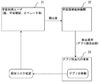
- FIG. 4A is a diagram showing an example of a business model using the spacecraft according to the present embodiment.
- the constellation user 41 is a space agency, an operator, or the like constructing a satellite constellation.
- a satellite constellation is a group of satellite systems that covers the entire surface of the earth by arranging a plurality of artificial satellites so that their communication ranges do not overlap with each other.
- the debris removal agent 42 is a company that receives a spacecraft placement fee (placement request) from the constellation user 41 and places the spacecraft on the plurality of artificial satellites.
- placement request spacecraft placement fee
- many satellites are put in the same orbit, so if one satellite becomes uncontrollable (artificial satellite failure), there is a risk that the satellite will collide with another satellite (business continuity crisis) ..
- the debris removal agent 42 changes the orbits of uncontrollable satellites by using the spacecraft according to the present embodiment in response to the orbit departure request from the constellation user 41, and Reduce (avoid) the risk of colliding with a constellation satellite. Then, the debris removal agent 42 receives the success fee from the constellation user 41.
- the debris is not limited to the above, but one or a small number of spacecraft are arranged for one orbit, and the propulsion unit mounted on the spacecraft is used to approach the debris to remove the debris. Can be removed.
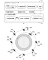
- FIG. 4B shows a plurality of artificial satellites 200a to 200h forming a satellite constellation and spacecrafts 100a to 100h arranged for the plurality of artificial satellites, respectively.
- FIG. 4B shows an example in which the orbit is changed (the altitude is lowered) by the spacecraft 100a when the artificial satellite 200a fails.
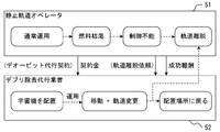
- FIG. 5 is a diagram showing an example of a business model using the spacecraft according to the present embodiment.
- the geostationary orbit operator 51 is an operator who operates a geostationary satellite.
- a geostationary satellite is an artificial satellite that orbits a circular orbit with an altitude of about 36,000 km at the same cycle as the earth's rotation cycle.
- the debris removal agent 52 is a agent that acts on behalf of the deorbit of the geostationary satellite operated by the geostationary orbit operator 51.
- Deorbit refers to removing the satellite from orbit. For example, the geostationary orbit operator 51 pays a contract fee to the debris removal agent 52 to enter into a deorbit agent contract.
- the geostationary orbit operator 51 requests the debris removal agent 52 to leave the artificial satellite orbit.
- the debris removal agent 52 changes the orbit of the uncontrollable artificial satellite.
- the uncontrollable satellite is deorbited (de-orbit).
- the departure from the orbit includes, for example, moving to an orbit where no other artificial satellite exists.
- the debris removal agent 52 receives a reward for success from the geostationary orbit operator.
- the fuel is depleted during the operation of the satellite.
- the residual amount of fuel in the satellite is highly uncertain, and the margin is required to ensure deorbit. Need to have.
- the satellite operator does not need to secure a fuel uncertainty margin or fuel for deorbit. As a result, the satellite operator can use it for orbit control etc. until the fuel is exhausted.
- FIG. 6 is a diagram showing the configuration of the laser irradiation system according to the present embodiment.
- the laser irradiation system includes a spacecraft 100, a monitoring device 110, and the like.
- the spacecraft 100 is an artificial satellite having a laser irradiation function.
- the spacecraft 100 includes an acquisition unit 101, a detection unit 102, a control unit 103, a propulsion unit 104, a communication unit 105, a laser device 106, a focus unit 107, a steering unit 108, and the like.
- the spacecraft 100 irradiates the debris 200 with the laser beam output by the laser device 106 via the focus unit 107 and the steering unit 108.
- the acquisition unit 101 is a functional unit that acquires an image using an imaging unit (not shown). In addition, the acquisition unit 101 acquires the reflected light of the search laser output from the laser device 106 described later.
- the acquisition unit 101 can also be regarded as various sensors.
- the detection unit 102 is a functional unit that acquires the detection information of the debris 200 based on the image or the reflected light acquired by the acquisition unit 101.
- the detection information includes the distance between the spacecraft 100 and the debris 200, the position, size, shape, captured image, rotation state (orientation), etc. of the debris 200.
- the detecting unit 102 acquires the distance between the spacecraft 100 and the debris 200 using Lidar (Light Detection and Ranging).
- the control unit 103 controls the focus unit 107 so that the laser emitted from the laser device 106 is focused on the debris 200 based on the distance between the spacecraft 100 and the debris 200. For example, when the focus unit 107 is an optical system, the focal length of the optical system is adjusted.
- the control unit 103 is a functional unit that determines the laser irradiation position on the debris 200 and the laser output value based on the detection information acquired by the detection unit 102. For example, the control unit 103 determines the laser irradiation position based on the position and orientation of the debris 200 detected by the detection unit 102, and the region suitable for laser irradiation.
- the region suitable for laser irradiation is a region excluding a portion (for example, a fuel tank) where danger may occur due to laser irradiation.
- the control unit 103 may determine the position and timing of laser irradiation in consideration of a safe area on the ground.
- the safe area is an area for dropping debris and the like that remain without being burned out when the debris 200 re-enters the atmosphere.
- the safe area is the sea which is more than tens to hundreds of nautical miles away from the routes and land of ships and aircrafts.
- the control unit 103 may acquire information regarding a region suitable for laser irradiation or a safe region from the monitoring device 110 described later via the communication unit 105.
- the propulsion unit 104 is a functional unit that controls the attitude or orbit of the spacecraft 100 by using a thrust generator (actuator) such as a thruster or a wheel to adjust the attitude required for laser irradiation.
- a thrust generator actuator
- the attitude control method is not particularly limited, and an existing method such as a triaxial stabilization method, a bias momentum method, a zero momentum method, or the like can be adopted.
- the communication unit 105 is a functional unit for communicating with the ground monitoring device 110. Through the communication unit 105, the spacecraft 100 acquires information about a rough position (coarse orbital position) of the debris 200, the area suitable for laser irradiation and a safe area, and the like.
- the laser device 106 is a device that outputs a laser.
- the laser device 106 outputs a high-intensity (high-power) laser by using a pulse laser system using fiber lasers in parallel. It is desirable that the laser device 106 be capable of outputting about three times the output value required to generate the ablation described below.
- the laser is not limited to the above, and various lasers such as a solid-state laser may be output. For example, when searching for the debris 200 or aiming the laser at the debris 200, a laser with a small output may be output.
- the light source for aiming and the light source for laser irradiation may be separate bodies. The aiming light source may also emit visible light.
- the focus unit 107 is a member for focusing the laser emitted by the laser device 106. Through the focus unit 107, the spacecraft 100 can emit a laser to the debris 200 even from a remote location.
- the focus unit 107 uses a general telescope, but is not limited to the telescope as long as it is a member for focusing the laser.
- the remote location is assumed to be located at a distance of about 20 to 1000 meters from the debris 200, but the distance between the spacecraft 100 and the debris 200 is not particularly limited.
- the steering unit 108 is a member for changing the irradiation direction of the laser output by the focus unit 107.
- a movable mirror can be used as the steering unit 108.
- the spacecraft 100 can easily direct the laser irradiation direction to the debris 200 even from a remote location. Further, even if the spacecraft 100 and the debris 200 do not exist in the same orbit, the laser irradiation direction can be easily directed to the debris 200 even from a remote place, so that there is a risk that the spacecraft 100 collides with the debris 200. It is reducing.
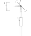
- FIG. 7 is a diagram showing an example of configurations of the focus unit 107 and the steering unit 108 according to the present embodiment.
- the laser output from the laser device 106 is gradually converged by passing through the focus unit 107. Then, the irradiation direction of the laser is changed by being reflected by the steering unit 108.
- the method of pointing the laser to the target is not limited to the above.
- the direction in which the laser is emitted may be changed by controlling the attitude of the spacecraft 100 itself without using the steering unit 108.
- the direction in which the laser is emitted may be changed by changing the direction of the focus unit 107.
- the focus unit 107 and the steering unit 108 are provided as a part of the spacecraft 100 in the present embodiment, they may be provided separately from the spacecraft 100.
- the monitoring device 110 is a device that detects a rough position of the debris 200 and transmits information on the detected debris 200 to the spacecraft 100. Further, the monitoring device 110 may transmit information about the area suitable for laser irradiation or a safe area, etc., to the spacecraft 100.
- the debris 200 is part of an artificial satellite or the like released from a collision or the like from a large satellite such as an uncontrollable artificial satellite or an artificial satellite that has become unnecessary after the operation ends (for example, Parts such as screws) may be included.
- the target of the debris 200 is not limited to the above, and includes objects existing in outer space (for example, meteorites).
- the size of the debris 200 is not particularly limited. Generally, an object existing in outer space can be detected from the ground with a size of 10 [cm] or more. However, the spacecraft 100 according to the present embodiment can detect debris 200 in outer space. Therefore, even an object of 10 cm or less can be detected.
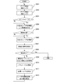
- FIG. 8 is a flowchart showing an example of processing according to this embodiment.
- step S801 the monitoring device 110 detects a rough orbit (position) of the debris 200. Then, the monitoring device 110 transmits the detected position of the debris 200 to the spacecraft 100.
- the detection unit 102 searches the debris 200 based on the rough position acquired above, and acquires the detection information of the debris 200. For example, the detection unit 102 acquires the distance between the spacecraft 100 and the debris 200, the position, size, shape, captured image, rotation state (posture), etc. of the debris 200 as the detection information.
- step S803 the control unit 103 determines whether the irradiation mode of the spacecraft 100 is the lock mode.
- the lock mode is a mode in which the debris 200 detected by the spacecraft 100 is irradiated with a laser. If it is the lock mode, the process proceeds to step S804, and if not, the process returns to step S801.
- step S804 the spacecraft 100 emits a laser and aims the laser. Specifically, the laser emitted by the laser device 106 converges by passing through the focus unit 107. Then, the steering unit 108 changes the irradiation direction.
- the control unit 103 controls the focus unit 107 so that the laser is focused on the debris 200 based on the distance (detection information) between the spacecraft 100 and the debris 200.
- the control unit 103 when aiming the laser, sets the output value of the laser to "small (first output value)".
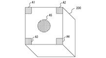
- FIG. 9 is a diagram showing an example of the irradiation position on the debris 200.
- a rotational torque is generated by irradiating a corner (for example, the areas A1 to A4) on each surface of the debris with a laser.
- an external force for moving the debris 200 can be applied.
- Alternately radiating laser light diagonally means, for example, radiating laser light in the order of area A1 ⁇ area A4 ⁇ area A1 ⁇ area A4.
- an external force for moving the debris 200 may be applied by irradiating the central portion (for example, the region A5) with a laser.
- step S805 the control unit 103 determines whether or not the aiming position and the actually irradiated position match.
- the control unit 103 acquires the actually irradiated position based on the image acquired by the acquisition unit 101, for example. If they match, the process proceeds to step S806; otherwise, the process returns to step S804.
- step S806 the spacecraft 100 emits a laser to irradiate the debris 200.
- the control unit 103 sets the laser output value to “large (second output value)”.
- step S807 the detection unit 102 detects the trajectory or attitude of the debris 200.
- step S808 the control unit 103 determines whether the control of the debris 200 is completed.
- the case where the control is completed is, for example, when the orbit control moves to a target orbit or when the debris 200 stops rotating (spins) in the attitude control. If the control is completed, this process is terminated, and if not, the process proceeds to step S809.
- step S809 the control unit 103 obtains the moment of inertia I or the center of gravity G of the debris 200 based on the above detection information.
- step S810 the control unit 103 updates various parameters. For example, when the attitude control of the debris 200 is performed, the control unit 103 matches the torque measured based on the above-described detection information (referred to as measured torque N1) and the assumed torque (referred to as assumed torque N2). To update the parameters.
- the assumed thrust F and the length r from the focus position to the center of gravity are updated (adjusted) as parameters.
- the assumed thrust F can be adjusted, for example, by changing the intensity (level) of the laser to be applied.
- the measured torque N1 is obtained as follows using the assumed acceleration ⁇ , the moment of inertia I, the measured initial posture change amount ⁇ 0, and the post-irradiation posture change amount ⁇ 1.
- the assumed torque N2 is obtained as follows using the above-described assumed thrust F and length r.
- a conversion table for holding and managing the above parameters for each debris may be provided.
- ⁇ Assumed torque N2 ⁇ N2 F ⁇ r
- step S811 the control unit 103 calculates the torque required to change the attitude of the debris 200 or move the debris 200.
- step S812 the control unit 103 obtains the laser irradiation position based on the above required torque.
- the irradiation position of the laser may be any position of the debris 200, but the irradiation position may be determined so that the laser is irradiated to a propulsive force enhancing member (special pad) described later. In addition, it is preferable to determine the irradiation position while avoiding a place where danger may occur due to laser irradiation.
- the control unit 103 may acquire, from the monitoring device 110 via the communication unit 105, a location where the above danger may occur. Further, the control unit 103 calculates the output value of the laser based on the above required torque. Then, the process returns to step S806.
- the trajectory or posture of the target object after laser irradiation is detected and fed back to the control of the laser irradiation position or output value to control the trajectory or posture of the target object.
- the special pad attached to the debris 200 in this embodiment will be described.
- the special pad according to the present embodiment is a member for generating ablation by irradiating the laser and increasing the reaction force of the plasma generated as a result.
- the special pad can be regarded as a propulsive force enhancing member.
- the special pad is supposed to be installed in advance before launching the satellite, but it may be installed in outer space. Further, the special pad is preferably attached to the areas A1 to A5 in FIG. 9, but the attachment position, shape, and size of the special pad are not particularly limited. For example, it may be attached to the surface of the debris 200 in a band shape, or may be attached to the entire surface of the debris 200. Further, a plurality of strip-shaped special pads may be provided so that the angle of the special pads can be changed.
- FIG. 10A shows the basic structure of the special pad 900 according to this embodiment.
- the special pad 900 is a member attached to the surface of the debris 200, and has a transparent member 901, an opaque member 902, and the like. Details of the structure of the special pad 900 will be described later.
- FIG. 10B shows a force (arrow 22) ejected by a part of the opaque member 902 and its reaction force ⁇ v (arrow 23) due to ablation as a result of the laser irradiation shown in FIG. 10A.
- FIG. 10B shows a force (arrow 22) ejected by a part of the opaque member 902 and its reaction force ⁇ v (arrow 23) due to ablation as a result of the laser irradiation shown in FIG. 10A.
- FIG. 10C shows an example in which the surface of the debris 200 is irradiated with the laser 21 without using the special pad 900.
- FIG. 10D shows a force (arrow 22) and a reaction force ⁇ v (arrow 23) thereof that eject a part of the debris 200 by ablation as a result of the laser irradiation shown in FIG. 10C.
- the reaction force ⁇ v is generated by the force (arrow 22) of the ejected substance released into outer space
- the reaction force ⁇ v which is several orders of magnitude, is generated by the force of the substance pushing the transparent member 901.
- FIG. 11 is a diagram showing an example of the special pad 900 according to the present embodiment.
- the special pad 900 according to this embodiment has a transparent member 901, an opaque member 902, a protective member 903, and the like.
- the transparent member 901 is a member that transmits the above laser.
- the shape of the transparent member 901 is not particularly limited, but in the present embodiment, an example of a sheet-shaped member will be described. It is desirable that the transparent member 901 is made of a material that is transparent even when it is exposed to atomic oxygen or radiation in outer space during the operation period of the artificial satellite (for example, 10 to 15 years). Having transparency means that laser (light) absorption or scattering does not occur or is within a predetermined range.
- the transparent member 901 is made of fluororesin will be described. This is because the bond energy of the C—F bond in the fluororesin is strong and it has heat resistance and oxidation resistance.
- the transparent member 901 may be transparent, and may be pure acrylic, quartz glass, or the like.
- the opaque member 902 is a member provided between the debris 200 and the transparent member 901.
- the shape of the opaque member 902 is not particularly limited, but in the present embodiment, an example of a sheet-shaped member will be described.
- the opaque member 902 has a characteristic that it absorbs and expands the laser described above, and at least a part of it is evaporated by the energy of the laser, turned into plasma, and ejected.
- the opaque member 902 is preferably an opaque member made of a material that easily evaporates (has a low boiling point) and has a boiling point that does not evaporate by solar heat.
- the opaque member 902 can be made of acrylic containing a black material (for example, black rhedium), for example.
- the opaque member 902 is not limited to the above acrylic. For example, alcohol may be used as the opaque member.
- the protection member 903 is a member provided on at least one surface of the special pad 900, and is used to protect the transparent member 901 and the like during the operation period of the artificial satellite.
- the protective member 903 preferably has at least one function of radiation resistance, light shielding property (prevents heat input by sunlight), and oxidation resistance (atomic oxygen resistance). Note that the protective member 903 may have a function of preventing rubbing with another object.
- the material of the protective member 903 is not particularly limited, but perfluorocarbon, silica, fluororesin, polyimide film (for example, Kapton (registered trademark)), metal such as aluminum, or the like can be used.
- the protective member 903 is preferably vaporized by laser irradiation. Note that the protective member 903 does not necessarily have to be provided.
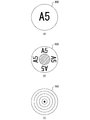
- a mark such as a symbol is added to the surface of the special pad 900 (for example, the surface of the protection member 903). This is for facilitating detection of the position of the special pad 900 and for identification when aiming the laser.
- 12A to 12C are diagrams showing an example of the mark.
- FIG. 12A shows an example in which characters are added to the surface of the special pad 900.
- the content of the character is not particularly limited.
- the character “A5” indicates that it is attached to the area A5 shown in FIG.
- the mark may be a symbol, a character, a figure, a one-dimensional code, a two-dimensional code, or the like.
- the surface may be colored as a mark.
- a region for laser irradiation hatchched portion in FIG. 12B
- a region for adding a mark may be separated.
- a line indicating the target may be added to the surface of the special pad 900 (FIG. 12C). Note that the above is an example, and can be appropriately changed according to the shape of the special pad 900 and the attachment site.
- the special pad 900 according to the present embodiment has a structure in which one or more transparent members 901 and opaque members 902 are alternately laminated.
- the number of layers is not particularly limited, but 10 to 100 layers are preferable.
- FIG. 11 shows an example of 50 layers.
- the transparent member 901 and the opaque member 902 have a laminated structure. Therefore, even if the laser irradiation is performed once and the opaque member 902 (Layer 1) is evaporated, the laser 21 is transmitted through the second-layer transparent member 901 (Layer 2) when the laser irradiation is performed next, The opaque member 902 (Layer 2) of the second layer is evaporated. With such a configuration, even when laser irradiation is repeated, the reaction force can be increased as long as one or more layers of the transparent member 901 and the opaque member 902 remain.
- the spacecraft 100 having the above configuration can remotely change the orbit and attitude of the debris 200. This eliminates the need for the spacecraft 100 to approach the debris 200, and the risk of collision between the spacecraft 100 and the debris 200 can be reduced.
- the spacecraft 100 since the spacecraft 100 has the above-described configuration, it can perform debris orbit control and attitude control of about 1 [t] even when using a small laser device with an output value of about 100 [w]. You can As a result, it is possible to reduce the size and cost of the spacecraft equipped with the laser device. Further, by performing laser irradiation on the above-mentioned special pad, it is possible to change the trajectory and posture of the debris even with a smaller laser device.
- the spacecraft 100 has the above-mentioned configuration, even if the debris 200 is not tracked, the orbit and attitude of the debris 200 can be changed by changing the direction of the laser with the steering means, for example. Thereby, the fuel for moving the spacecraft 100 can be reduced.
- the spacecraft 100 since the spacecraft 100 has the above configuration, it is possible to control the orbit and attitude of the spacecraft 100 itself and the debris 200 only by laser irradiation without using a propulsion device (for example, a thruster). As a result, it is not necessary to secure fuel or the like for the artificial satellite to move after it has finished operating, so that operating costs can be suppressed.
- a propulsion device for example, a thruster
Landscapes
- Engineering & Computer Science (AREA)
- Remote Sensing (AREA)
- Aviation & Aerospace Engineering (AREA)
- Physics & Mathematics (AREA)
- Astronomy & Astrophysics (AREA)
- General Physics & Mathematics (AREA)
- Radar, Positioning & Navigation (AREA)
- Chemical & Material Sciences (AREA)
- Combustion & Propulsion (AREA)
- Automation & Control Theory (AREA)
- Control Of Position, Course, Altitude, Or Attitude Of Moving Bodies (AREA)
- Optical Radar Systems And Details Thereof (AREA)
- On-Site Construction Work That Accompanies The Preparation And Application Of Concrete (AREA)
- Length Measuring Devices By Optical Means (AREA)
- Investigating Materials By The Use Of Optical Means Adapted For Particular Applications (AREA)
Priority Applications (6)
| Application Number | Priority Date | Filing Date | Title |
|---|---|---|---|
| EP19910932.3A EP3915883A4 (en) | 2019-01-21 | 2019-01-21 | SPACECRAFT AND CONTROL SYSTEM |
| CN201980089674.4A CN113348133B (zh) | 2019-01-21 | 2019-01-21 | 航天器、控制系统 |
| PCT/JP2019/001655 WO2020152744A1 (ja) | 2019-01-21 | 2019-01-21 | 宇宙機、制御システム |
| CA3127293A CA3127293C (en) | 2019-01-21 | 2019-01-21 | Spacecraft and control system |
| US17/423,995 US12049331B2 (en) | 2019-01-21 | 2019-01-21 | Spacecraft and control system |
| JP2020567677A JP7117399B2 (ja) | 2019-01-21 | 2019-01-21 | 宇宙機、制御システム |
Applications Claiming Priority (1)
| Application Number | Priority Date | Filing Date | Title |
|---|---|---|---|
| PCT/JP2019/001655 WO2020152744A1 (ja) | 2019-01-21 | 2019-01-21 | 宇宙機、制御システム |
Publications (1)
| Publication Number | Publication Date |
|---|---|
| WO2020152744A1 true WO2020152744A1 (ja) | 2020-07-30 |
Family
ID=71735652
Family Applications (1)
| Application Number | Title | Priority Date | Filing Date |
|---|---|---|---|
| PCT/JP2019/001655 Ceased WO2020152744A1 (ja) | 2019-01-21 | 2019-01-21 | 宇宙機、制御システム |
Country Status (6)
| Country | Link |
|---|---|
| US (1) | US12049331B2 (https=) |
| EP (1) | EP3915883A4 (https=) |
| JP (1) | JP7117399B2 (https=) |
| CN (1) | CN113348133B (https=) |
| CA (1) | CA3127293C (https=) |
| WO (1) | WO2020152744A1 (https=) |
Cited By (3)
| Publication number | Priority date | Publication date | Assignee | Title |
|---|---|---|---|---|
| JPWO2022234669A1 (https=) * | 2021-05-07 | 2022-11-10 | ||
| JPWO2022249430A1 (https=) * | 2021-05-28 | 2022-12-01 | ||
| WO2022249428A1 (ja) * | 2021-05-28 | 2022-12-01 | 三菱電機株式会社 | 測距機能を備える衛星減速装置 |
Families Citing this family (6)
| Publication number | Priority date | Publication date | Assignee | Title |
|---|---|---|---|---|
| TWI396824B (zh) * | 2010-03-02 | 2013-05-21 | Witrins S R O | 用於光學測量產品表面之方法及器件 |
| WO2021221035A1 (ja) * | 2020-04-27 | 2021-11-04 | 三菱電機株式会社 | 宇宙状況監視事業装置、地上設備、宇宙交通事業装置、宇宙交通管理システム、および観測衛星 |
| CA3214943A1 (en) * | 2021-05-03 | 2023-01-12 | Kerri Cahoy | Localizing, waking-up, and estimating direction of femto-satellites |
| CN115402540B (zh) * | 2022-11-02 | 2023-02-28 | 哈尔滨工业大学 | 一种用于辅助变轨的适配装置和变轨方法 |
| US12560737B2 (en) | 2023-03-08 | 2026-02-24 | Eagle Technology, Llc | Outer space-based debris detection system and associated methods |
| CN118913310A (zh) * | 2024-07-22 | 2024-11-08 | 华中科技大学 | 一种重力卫星星间测距地面验证系统及验证方法 |
Citations (6)
| Publication number | Priority date | Publication date | Assignee | Title |
|---|---|---|---|---|
| US5153407A (en) * | 1989-12-30 | 1992-10-06 | Deutsche Forschungsanstalt Fuer Luft- Und Raumfahrt E.V. | Method and device for removing space debris |
| JPH0628696A (ja) * | 1993-06-28 | 1994-02-04 | Hitachi Ltd | 情報記録方法 |
| JPH10244651A (ja) * | 1997-03-06 | 1998-09-14 | Sony Corp | レーザ製版装置 |
| JP2013512145A (ja) * | 2009-11-25 | 2013-04-11 | ポウロス エアー アンド スペース | 不安定なスペース・デブリスの安定化 |
| CN104155747A (zh) * | 2014-07-29 | 2014-11-19 | 中国科学院长春光学精密机械与物理研究所 | 基于分离式多望远镜形式的激光合束空间碎片清除系统 |
| JP2015174647A (ja) | 2014-03-18 | 2015-10-05 | アストロスケール プライベート リミテッド | 宇宙用装置、デブリ除去システム及びデブリ除去方法 |
Family Cites Families (8)
| Publication number | Priority date | Publication date | Assignee | Title |
|---|---|---|---|---|
| JPH05254500A (ja) * | 1992-03-13 | 1993-10-05 | Mitsubishi Electric Corp | 宇宙浮遊物検出および粉砕方法 |
| US5421540A (en) * | 1992-08-26 | 1995-06-06 | Ting; Paul C. | Method and apparatus for disposal/recovery of orbiting space debris |
| US6530212B1 (en) * | 2000-02-25 | 2003-03-11 | Photonic Associates | Laser plasma thruster |
| JP5519123B2 (ja) * | 2008-06-10 | 2014-06-11 | 株式会社片岡製作所 | レーザ加工機 |
| US20110302906A1 (en) * | 2010-06-15 | 2011-12-15 | John Elihu Sinko | Laser Tractor Beam |
| JP5952875B2 (ja) | 2014-09-30 | 2016-07-13 | 株式会社片岡製作所 | レーザ加工機、レーザ加工機のワーク歪補正方法 |
| US20180222604A1 (en) * | 2017-02-09 | 2018-08-09 | Thales | Satellite propelled by laser ablation |
| CN108263641A (zh) * | 2018-01-25 | 2018-07-10 | 中国人民解放军战略支援部队航天工程大学 | 一种天基激光飞行装置 |
-
2019
- 2019-01-21 CN CN201980089674.4A patent/CN113348133B/zh active Active
- 2019-01-21 US US17/423,995 patent/US12049331B2/en active Active
- 2019-01-21 EP EP19910932.3A patent/EP3915883A4/en active Pending
- 2019-01-21 WO PCT/JP2019/001655 patent/WO2020152744A1/ja not_active Ceased
- 2019-01-21 CA CA3127293A patent/CA3127293C/en active Active
- 2019-01-21 JP JP2020567677A patent/JP7117399B2/ja active Active
Patent Citations (6)
| Publication number | Priority date | Publication date | Assignee | Title |
|---|---|---|---|---|
| US5153407A (en) * | 1989-12-30 | 1992-10-06 | Deutsche Forschungsanstalt Fuer Luft- Und Raumfahrt E.V. | Method and device for removing space debris |
| JPH0628696A (ja) * | 1993-06-28 | 1994-02-04 | Hitachi Ltd | 情報記録方法 |
| JPH10244651A (ja) * | 1997-03-06 | 1998-09-14 | Sony Corp | レーザ製版装置 |
| JP2013512145A (ja) * | 2009-11-25 | 2013-04-11 | ポウロス エアー アンド スペース | 不安定なスペース・デブリスの安定化 |
| JP2015174647A (ja) | 2014-03-18 | 2015-10-05 | アストロスケール プライベート リミテッド | 宇宙用装置、デブリ除去システム及びデブリ除去方法 |
| CN104155747A (zh) * | 2014-07-29 | 2014-11-19 | 中国科学院长春光学精密机械与物理研究所 | 基于分离式多望远镜形式的激光合束空间碎片清除系统 |
Cited By (8)
| Publication number | Priority date | Publication date | Assignee | Title |
|---|---|---|---|---|
| JPWO2022234669A1 (https=) * | 2021-05-07 | 2022-11-10 | ||
| WO2022234669A1 (ja) * | 2021-05-07 | 2022-11-10 | スカパーJsat株式会社 | 推力発生装置、宇宙機 |
| JP7717155B2 (ja) | 2021-05-07 | 2025-08-01 | スカパーJsat株式会社 | 推力発生装置、宇宙機 |
| JPWO2022249430A1 (https=) * | 2021-05-28 | 2022-12-01 | ||
| WO2022249430A1 (ja) * | 2021-05-28 | 2022-12-01 | 三菱電機株式会社 | 宇宙物体軌道変更装置 |
| WO2022249428A1 (ja) * | 2021-05-28 | 2022-12-01 | 三菱電機株式会社 | 測距機能を備える衛星減速装置 |
| JPWO2022249428A1 (https=) * | 2021-05-28 | 2022-12-01 | ||
| JP7325691B2 (ja) | 2021-05-28 | 2023-08-14 | 三菱電機株式会社 | 宇宙物体軌道変更装置 |
Also Published As
| Publication number | Publication date |
|---|---|
| CN113348133A (zh) | 2021-09-03 |
| CA3127293C (en) | 2023-09-19 |
| JP7117399B2 (ja) | 2022-08-12 |
| US12049331B2 (en) | 2024-07-30 |
| CA3127293A1 (en) | 2020-07-30 |
| JPWO2020152744A1 (https=) | 2020-07-30 |
| US20220127018A1 (en) | 2022-04-28 |
| EP3915883A1 (en) | 2021-12-01 |
| CN113348133B (zh) | 2024-10-11 |
| EP3915883A4 (en) | 2022-08-31 |
Similar Documents
| Publication | Publication Date | Title |
|---|---|---|
| JP7117399B2 (ja) | 宇宙機、制御システム | |
| Bonnal et al. | Just in time collision avoidance–A review | |
| US20240300221A1 (en) | Propulsion Strengthening Member | |
| Soulard et al. | ICAN: A novel laser architecture for space debris removal | |
| Ebisuzaki et al. | Demonstration designs for the remediation of space debris from the International Space Station | |
| KR101872612B1 (ko) | 우주 쓰레기 제거용 위성 | |
| Phipps et al. | A spaceborne, pulsed UV laser system for re-entering or nudging LEO debris, and re-orbiting GEO debris | |
| US20110302906A1 (en) | Laser Tractor Beam | |
| Kumar et al. | Despinning orbital debris before docking using laser ablation | |
| Quinn et al. | Space-based application of the CAN laser to LIDAR and orbital debris remediation | |
| Khomich et al. | Laser-optical technologies for space debris removal | |
| Gibbings et al. | Potential of laser-induced ablation for future space applications | |
| Phipps et al. | Is laser space propulsion practical? | |
| H Choi et al. | Assessment study of small space debris removal by laser satellites | |
| RU2781066C1 (ru) | Космический аппарат и система управления | |
| Vasile et al. | Orbital debris removal with solar concentrators | |
| Phipps | Laser space debris removal: now, not later | |
| Avdeev et al. | Nuclear powered spaceborne laser for orbital debris removal | |
| Huang et al. | Space Debris Removal Ground-Based Laser Nudge De-Orbiting System and Modeling Process | |
| Scholl et al. | Using the Useless: Laser Propulsion Unit for Post-Mission Disposal using a Launch Adapter as Propellant Material | |
| JP7717155B2 (ja) | 推力発生装置、宇宙機 | |
| Zhang et al. | Technologies of Active Debris Removal | |
| Scharring et al. | Orbital Re-focusing of High Energy Laser Beams from Ground for Laser-ablative Post-Mission Disposal and Debris Removal | |
| Maddock et al. | Conceptual design of a multi-mirror system for asteroid deflection | |
| Peeters et al. | Active small-scale space debris removal by a space-based laser |
Legal Events
| Date | Code | Title | Description |
|---|---|---|---|
| 121 | Ep: the epo has been informed by wipo that ep was designated in this application |
Ref document number: 19910932 Country of ref document: EP Kind code of ref document: A1 |
|
| ENP | Entry into the national phase |
Ref document number: 2020567677 Country of ref document: JP Kind code of ref document: A Ref document number: 3127293 Country of ref document: CA |
|
| NENP | Non-entry into the national phase |
Ref country code: DE |
|
| WWE | Wipo information: entry into national phase |
Ref document number: 2021122409 Country of ref document: RU |
|
| ENP | Entry into the national phase |
Ref document number: 2019910932 Country of ref document: EP Effective date: 20210823 |