WO2020149160A1 - 極低温冷凍機、冷凍能力抑制器、および冷凍能力抑制器の使用方法 - Google Patents
極低温冷凍機、冷凍能力抑制器、および冷凍能力抑制器の使用方法 Download PDFInfo
- Publication number
- WO2020149160A1 WO2020149160A1 PCT/JP2020/000023 JP2020000023W WO2020149160A1 WO 2020149160 A1 WO2020149160 A1 WO 2020149160A1 JP 2020000023 W JP2020000023 W JP 2020000023W WO 2020149160 A1 WO2020149160 A1 WO 2020149160A1
- Authority
- WO
- WIPO (PCT)
- Prior art keywords
- pipe
- suppressor
- cryogenic refrigerator
- refrigerating capacity
- pressure
- Prior art date
- Legal status (The legal status is an assumption and is not a legal conclusion. Google has not performed a legal analysis and makes no representation as to the accuracy of the status listed.)
- Ceased
Links
Images



Classifications
-
- F—MECHANICAL ENGINEERING; LIGHTING; HEATING; WEAPONS; BLASTING
- F25—REFRIGERATION OR COOLING; COMBINED HEATING AND REFRIGERATION SYSTEMS; HEAT PUMP SYSTEMS; MANUFACTURE OR STORAGE OF ICE; LIQUEFACTION SOLIDIFICATION OF GASES
- F25B—REFRIGERATION MACHINES, PLANTS OR SYSTEMS; COMBINED HEATING AND REFRIGERATION SYSTEMS; HEAT PUMP SYSTEMS
- F25B41/00—Fluid-circulation arrangements
- F25B41/20—Disposition of valves, e.g. of on-off valves or flow control valves
- F25B41/24—Arrangement of shut-off valves for disconnecting a part of the refrigerant cycle, e.g. an outdoor part
-
- F—MECHANICAL ENGINEERING; LIGHTING; HEATING; WEAPONS; BLASTING
- F25—REFRIGERATION OR COOLING; COMBINED HEATING AND REFRIGERATION SYSTEMS; HEAT PUMP SYSTEMS; MANUFACTURE OR STORAGE OF ICE; LIQUEFACTION SOLIDIFICATION OF GASES
- F25B—REFRIGERATION MACHINES, PLANTS OR SYSTEMS; COMBINED HEATING AND REFRIGERATION SYSTEMS; HEAT PUMP SYSTEMS
- F25B41/00—Fluid-circulation arrangements
- F25B41/30—Expansion means; Dispositions thereof
-
- F—MECHANICAL ENGINEERING; LIGHTING; HEATING; WEAPONS; BLASTING
- F25—REFRIGERATION OR COOLING; COMBINED HEATING AND REFRIGERATION SYSTEMS; HEAT PUMP SYSTEMS; MANUFACTURE OR STORAGE OF ICE; LIQUEFACTION SOLIDIFICATION OF GASES
- F25B—REFRIGERATION MACHINES, PLANTS OR SYSTEMS; COMBINED HEATING AND REFRIGERATION SYSTEMS; HEAT PUMP SYSTEMS
- F25B9/00—Compression machines, plants or systems, in which the refrigerant is air or other gas of low boiling point
Definitions
- the present invention relates to a cryogenic refrigerator, a refrigerating capacity suppressor, and a method of using the refrigerating capacity suppressor.
- a helium compressor unit that supplies helium gas discharged from a helium compressor to a refrigerator is provided with a controller that changes the capacity of the compressor according to the load of the refrigerator.
- Cryogenic refrigerators are often used for recondensing liquid helium among liquid refrigerants.
- Liquid helium is stored in a helium liquid tank and is used for cooling equipment contained in the liquid tank, for example, superconducting equipment including a superconducting coil.
- Helium vaporized from the liquid tank is condensed by the cryogenic refrigerator and returned to the liquid tank as liquid helium again.
- Such circulation of helium is also referred to as zero boil-off technology, which can minimize evaporation loss of liquid helium.
- an electric heater or other heating device can be installed in the helium bath.
- the heat generated from the superconducting equipment and the vaporization of helium by heating equipment, which is performed as necessary, and the recondensation of helium by the cryogenic refrigerator balance, and the helium liquid tank is continuously maintained at the desired positive pressure.
- this balance may be lost.
- the amount of heat generated from the superconducting device decreases, such as when the superconducting device is not used, the helium recondensation by the cryogenic refrigerator becomes excessive, the pressure in the helium liquid tank decreases, and further negative pressure can occur.
- the cryogenic refrigerator is new, the refrigerating capacity is maximized, so that such supercooling is likely to occur.
- a safety device can be installed in a system applying a zero boil-off technology such as a magnetic resonance imaging (MRI) system. If the heating by the electric heater is continued for a long time (for example, half a day or more), the safety device may be activated, and as a result, the energization of the heater may be stopped. The safety device can shut down the entire system, not just the heater. In that case, the system must be restarted after manually confirming that it is in a safe situation, which is complicated. In addition, the system may not be able to operate as planned, which is a problem.
- MRI magnetic resonance imaging
- Another method for recovering the pressure in the helium liquid tank is to measure the pressure in the liquid tank and control the refrigerating capacity of the cryogenic refrigerator based on the measured pressure.
- the configuration for controlling the refrigerating capacity is often not incorporated in the cryogenic refrigerator. Even with such a cryogenic refrigerator, it would be convenient if the refrigerating capacity could be temporarily changed in order to prevent supercooling that could cause imbalance in the helium circulation.
- One of the exemplary objects of an aspect of the present invention is to provide a cryogenic refrigerator and a refrigerating capacity suppressor capable of adjusting the refrigerating capacity.
- a cryogenic refrigerator includes a compressor, a cold head, a high pressure line connecting the compressor to the cold head, a gas inlet for receiving a refrigerant gas from the high pressure line, and a refrigerant gas in the high pressure line.
- a refrigerating capacity suppressor including a plurality of internal pipes that connect the gas inlet to the gas outlet in parallel, and a switching valve that switches the plurality of internal pipes. The plurality of internal pipes cause different pressure drops in the refrigerant gas flow from the gas inlet to the gas outlet.
- a refrigerating capacity suppressor of a cryogenic refrigerator is connected to a gas inlet connectable to a compressor or a refrigerant gas pipe connected to the compressor, a cold head, or a cold head.
- a gas outlet connectable to the refrigerant gas pipe, a plurality of internal pipes that connect the gas inlet to the gas outlet in parallel, and a switching valve that switches the plurality of internal pipes are provided.
- the plurality of internal pipes cause different pressure drops in the refrigerant gas flow from the gas inlet to the gas outlet.
- the plurality of internal pipes of the refrigeration capacity suppressor include a main pipe and a pressure loss pipe that causes a large pressure loss in the refrigerant gas flow as compared with the main pipe.
- This method is to switch the switching valve to the pressure loss pipe during new installation of the cryogenic refrigerator at the site where the cryogenic refrigerator is used, or during maintenance of the existing cryogenic refrigerator, and During maintenance of the cryogenic refrigerator, the switching valve is switched to the main pipe or another pressure loss pipe that causes a pressure loss smaller than the pressure loss pipe among the plurality of internal pipes.
- FIG. 3A to 3E are perspective views schematically showing an example of internal piping of the refrigeration capacity suppressor according to the embodiment.
- FIG. 4A to FIG. 4C are schematic diagrams for explaining the operation and usage of the refrigeration capacity suppressor according to the embodiment.
- FIG. 1 is a diagram schematically showing a cryogenic refrigerator 10 according to an embodiment.
- the cryogenic refrigerator 10 includes a compressor 12, a cold head 14, a piping system 16, and a refrigerating capacity suppressor 18.
- the cryogenic refrigerator 10 is used as a recondenser for a liquid refrigerant provided in a superconducting system (for example, a magnetic resonance imaging (MRI) system) having a superconducting device such as a superconducting electromagnet.
- the superconducting device is cooled below the critical temperature by being immersed in liquid helium or other suitable liquid refrigerant or in thermal contact with the liquid refrigerant.
- Such systems typically have a magnetic shield 20 to prevent high magnetic field leakage to the outside.
- the cold head 14 is located within the magnetic shield 20 along with the superconducting equipment, while the compressor 12 is typically located outside the magnetic shield 20.
- the compressor 12 is configured to collect the refrigerant gas from the cold head 14, pressurize the collected refrigerant gas, and supply the refrigerant gas to the cold head 14 again.
- the cold head 14, also called an expander, has a room temperature part 21 and at least one low temperature part 22. As shown in the figure, when the cold head 14 is a two-stage type, the cold head 14 has a low temperature section 22 in each of the first stage and the second stage. The cold head 14 may be a single stage type.
- the low temperature section 22 is also called a cooling stage.
- the refrigeration cycle of the cryogenic refrigerator 10 is configured by circulating the refrigerant gas between the compressor 12 and the cold head 14 with an appropriate combination of pressure fluctuation and volume fluctuation of the refrigerant gas in the cold head 14. Then, the low temperature section 22 is cooled to a desired cryogenic temperature.
- the low temperature section 22 cools a condenser (not shown). Thereby, the low temperature part 22 liquefies the vaporized liquid refrigerant again. Alternatively, the low temperature section 22 can cool the thermally coupled object to be cooled to the target cooling temperature.
- the refrigerant gas for the cryogenic refrigerator 10 is typically helium gas, but any other suitable gas may be used. For the sake of understanding, the direction in which the refrigerant gas flows is shown by an arrow in FIG.
- the cryogenic refrigerator 10 is, for example, a two-stage Gifford-McMahon (GM) refrigerator, but may be a pulse tube refrigerator, a Stirling refrigerator, or another type of cryogenic refrigerator. May be.
- the cold head 14 has different configurations depending on the type of cryogenic refrigerator.
- the compressor 12 can use the same structure regardless of the type of the cryogenic refrigerator.
- the pressure of the refrigerant gas supplied from the compressor 12 to the cold head 14 and the pressure of the refrigerant gas recovered from the cold head 14 to the compressor 12 are both considerably higher than the atmospheric pressure, and the first high pressure and the high pressure, respectively. It can be called the second high pressure.
- the first high pressure and the second high pressure are also simply referred to as high pressure and low pressure, respectively.
- the high pressure is in the range of about 2-3 MPa and the low pressure is in the range of about 0.5-1.5 MPa.
- the pressure of the liquid refrigerant recondensed by the cold head 14 is about atmospheric pressure.
- the compressor 12 has a discharge port 12a and a suction port 12b.
- the discharge port 12a is a refrigerant gas outlet provided in the compressor 12 for delivering the refrigerant gas whose pressure has been increased to a high pressure by the compressor 12, and the suction port 12b compresses the low pressure refrigerant gas. Is an inlet for refrigerant gas provided in the compressor 12 for reception in the machine 12.
- the cold head 14 has a high pressure port 14a and a low pressure port 14b.
- the high-pressure port 14 a is an inlet for the refrigerant gas provided in the room temperature portion 21 of the cold head 14 to receive the high-pressure working gas inside the low temperature portion 22 of the cold head 14.
- the low-pressure port 14 b is provided in the room temperature part 21 of the cold head 14 in order to discharge the low-pressure refrigerant gas decompressed by the expansion of the refrigerant gas inside the low temperature part 22 of the cold head 14 from the cold head 14. Is the exit.
- the piping system 16 connects the compressor 12 and the cold head 14 so as to circulate the refrigerant gas between them.
- the piping system 16 is provided separately from a circulation circuit of a refrigerant fluid that cools a superconducting device such as liquid helium. Therefore, the refrigerant gas such as helium gas flowing through the piping system 16 is not mixed with the refrigerant fluid.
- the piping system 16 also penetrates the magnetic shield 20 because the compressor 12 is outside the magnetic shield 20 and the cold head 14 is inside the magnetic shield 20 as described above.
- the piping system 16 includes a high pressure line 24 connecting the discharge port 12a of the compressor 12 to the high pressure port 14a of the cold head 14, and a low pressure line 26 connecting the suction port 12b of the compressor 12 to the low pressure port 14b of the cold head 14. Equipped with. Therefore, the high-pressure refrigerant gas is supplied from the compressor 12 to the cold head 14 through the high-pressure line 24, and the low-pressure refrigerant gas is recovered from the cold head 14 through the low-pressure line 26 to the compressor 12.
- the high pressure line 24 has a high pressure upstream pipe 24a connected to the discharge port 12a and a high pressure downstream pipe 24b connected to the high pressure port 14a.
- the high-pressure upstream pipe 24a and the high-pressure downstream pipe 24b are, for example, flexible pipes or flexible hoses, or may be rigid pipes.
- the low pressure line 26 may be formed of a flexible tube or a rigid tube.
- the refrigeration capacity suppressor 18 is provided separately from the compressor 12 and is provided in the piping system 16.
- the refrigeration capacity suppressor 18 is connected in the middle of the high pressure line 24.
- the refrigeration capacity suppressor 18 is arranged on the cold head 14 side with respect to the magnetic shield 20, for example.
- the refrigerating capacity suppressor 18 includes one gas inlet 28 that receives the refrigerant gas from the high-pressure line 24 and one gas outlet 30 that sends the refrigerant gas to the high-pressure line 24.
- the gas inlet 28 and the gas outlet 30 are detachably connected to the high pressure upstream pipe 24a and the high pressure downstream pipe 24b, respectively.
- An exemplary internal configuration of the refrigeration capacity suppressor 18 will be described later in detail.
- the gas inlet 28 and the gas outlet 30 are detachable joints such as a self-sealing coupling, and the high pressure upstream pipe 24a and the high pressure downstream pipe 24b are easily attached to the gas inlet 28 and the gas outlet 30, respectively. Or it can be removed.
- the gas outlet 30 may not be detachably connected to the cold head 14 via the high pressure downstream pipe 24b, but may be directly connectable to the high pressure port 14a of the cold head 14.
- the gas inlet 28 may be directly connectable to the discharge port 12a of the compressor 12 rather than being removably connected to the compressor 12 via the high pressure upstream pipe 24a.
- the refrigerating capacity suppressor 18 includes a gas discharge port 32 and a relief line 34.
- the relief line 34 connects the gas discharge port 32 to the low pressure line 26.
- the relief line 34 is detachably connected to the low pressure line 26.
- the relief line 34 may be detachably connected to the gas outlet 32.
- the refrigeration capacity suppressor 18 is detachably connected to the compressor 12 and the cold head 14 and is configured as a portable unit.
- the high pressure line 24 is composed of one pipe like the low pressure line 26 instead of the refrigerating capacity suppressor 18, the high pressure upstream pipe 24a, and the high pressure downstream pipe 24b. sell.
- the high-pressure upstream pipe 24a and the high-pressure downstream pipe 24b may be directly connected.
- the refrigerating capacity suppressor 18 is manufactured, for example, by the manufacturer of the cryogenic refrigerator 10 and provided to the user as an accessory to the cryogenic refrigerator 10.
- the main power source 19 may be, for example, a commercial power source or a power supply device connected to the commercial power source.
- the compressor 12, the cold head 14, and the refrigerating capacity suppressor 18 are each connected to the main power source 19 by power supply wiring. Therefore, it is not necessary to separately prepare a dedicated power source for the refrigeration capacity suppressor 18.
- various known configurations can be adopted for the power supply system of the cryogenic refrigerator 10.
- the compressor 12 may be connected to the main power supply 19, and the cold head 14 and the refrigerating capacity suppressor 18 may be powered by the compressor 12.
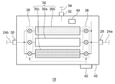
- FIG. 2 is a diagram schematically showing the refrigerating capacity suppressor 18 according to the embodiment.
- the refrigerating capacity suppressor 18 includes a plurality of internal pipes 36 that connect the gas inlet 28 to the gas outlet 30 in parallel, and a switching valve 38 that switches the plurality of internal pipes 36.
- the plurality of internal pipes 36 and the switching valve 38 are housed in a housing 40.
- the gas inlet 28, the gas outlet 30, and the gas discharge port 32 are provided on the surface of the housing 40.
- the plurality of internal pipes 36 cause different pressure losses in the refrigerant gas flow from the gas inlet 28 to the gas outlet 30.
- the plurality of internal pipes 36 includes one main pipe 36a and at least one pressure loss pipe.
- the main pipe 36a refers to a pipe of the plurality of internal pipes 36 that brings a minimum pressure loss to the refrigerant gas flow.
- the pressure loss pipe brings a large pressure loss to the refrigerant gas flow flowing through the pipe as compared with the main pipe 36a. Where multiple pressure drop lines are provided, they cause different pressure drops in the refrigerant gas flow from the gas inlet 28 to the gas outlet 30.
- the number of pressure loss pipes is not particularly limited, and may be only one, or may be three or more. Considering the ease of handling such as carrying the refrigerating capacity suppressor 18, the pressure loss piping may be, for example, 2 to 4. Including the main pipe 36a, the number of the internal pipes 36 may be, for example, 3 to 5.
- two pressure loss pipes are incorporated in the refrigerating capacity suppressor 18, and these are hereinafter referred to as a first pressure loss pipe 36b and a second pressure loss pipe 36c.
- the second pressure loss pipe 36c brings about a larger pressure loss in the refrigerant gas flow than the main pipe 36a. Therefore, the pressure loss given to the refrigerant gas flow increases in the order of the main pipe 36a, the first pressure loss pipe 36b, and the second pressure loss pipe 36c.
- the internal pipe 36 is made of a non-magnetic material, for example, a non-magnetic metal such as copper.
- the internal pipe 36 may be formed of a synthetic resin material.
- each component of the refrigerating capacity suppressor 18, for example, the housing 40 may also be formed of a non-magnetic material.
- the refrigeration capacity suppressor 18 it is advantageous to use the refrigeration capacity suppressor 18 in whole or in large part with a non-magnetic material for use in a strong magnetic field environment such as the magnetic shield 20.
- the components of the refrigerating capacity suppressor 18 such as the internal piping 36 and the housing 40 are made of a radiation resistant material or a material compatible with the environment. May be done.
- a plurality of internal pipes 36 branch from the gas inlet 28 and join the gas outlet 30.
- the plurality of internal pipes 36 are arranged in parallel with each other.
- Each internal pipe 36 extends linearly.
- Each internal pipe 36 has the same length and the same width (for example, diameter).
- the arrangement, shape, and size of the internal pipe 36 are merely examples and are not particularly limited.
- the internal pipe 36 may be a cylindrical pipe or a rectangular pipe.
- the internal pipe 36 is not limited to a straight pipe and may be curved.
- the internal pipes 36 may have different dimensions.
- the switching valve 38 is operable so that the gas inlet 28 and the gas outlet 30 are connected by any one internal pipe 36.
- the refrigerant gas may flow from the gas inlet 28 to the gas outlet 30 through the selected one internal pipe 36. Refrigerant gas does not flow to the other unselected internal pipes 36.
- the switching valve 38 operates to connect the gas inlet 28 and the gas outlet 30 at the same time with two or more internal pipes 36 when necessary, for example, to increase the refrigerant gas flow rate. May be.
- the switching valve 38 is provided at both a branch portion from the gas inlet 28 to the internal pipe 36 and a confluence portion from the internal pipe 36 to the gas outlet 30.
- the branch portions are provided with the same number of opening/closing valves as the number of internal pipes 36, and each opening/closing valve opens/closes the upstream end of the corresponding internal pipe 36.
- the merging portion is provided with the same number of open/close valves as the number of internal pipes 36, and each open/close valve opens/closes the downstream end of the corresponding internal pipe 36.
- the on-off valve may be an electrically driven valve such as a solenoid valve or an electric valve.
- the open/close valve may be a manual valve.
- the open/close valves at both the upstream and downstream ends of any one of the internal pipes 36 are opened, and the open/close valves at both the upstream and downstream ends of the other internal pipe 36 are closed.
- the refrigerant gas flows from the gas inlet 28 to the gas outlet 30 through the internal pipe 36 in which the upstream and downstream open/close valves are opened.
- the refrigerant gas flows from the high pressure upstream pipe 24a to the high pressure downstream pipe 24b through the refrigeration capacity suppressor 18.
- the switching valve 38 be composed of a plurality of open/close valves.
- the specific configuration of the switching valve 38 is not particularly limited, and may be a three-way valve, a four-way valve, a five-way valve, or another switching valve. Further, the switching valve 38 may be installed only on one side (for example, the branch portion) instead of both the branch portion and the merging portion.
- the refrigerating capacity suppressor 18 may include the operation unit 42 of the switching valve 38.
- the operation unit 42 may include an operation tool such as an operation switch or an operation button that is installed in the housing 40 and that can be operated manually. When the operation unit 42 is operated, the switching valve 38 switches the internal pipe 36.
- the relief line 34 branches between the gas inlet 28 and the switching valve 38.
- the relief line 34 has a relief valve 44.
- the relief valve 44 is closed when the refrigerant gas pressure at the gas inlet 28 (or the differential pressure between the high pressure line 24 and the low pressure line 26) is below a specified pressure value, and is opened when it exceeds the specified pressure value. Should the pressure at the gas inlet 28 become excessively high due to clogging of the internal piping 36 or malfunction of the switching valve 38, the pressure causes the relief valve 44 to open and the pressure to be released to the low pressure line 26.
- FIGS. 3B to 3E are perspective views schematically showing an example of the internal pipe 36 of the refrigerating capacity suppressor 18 according to the embodiment.
- FIG. 3A shows the main pipe 36a
- FIGS. 3B to 3E show the first pressure loss pipe 36b.
- the example illustrated in FIGS. 3B to 3E may be used as the second pressure loss pipe 36c.
- the main pipe 36a is a single pipe.
- the main pipe 36a is, for example, a cylindrical straight pipe.
- the inside of the main pipe 36a is a single cavity and is not provided with protrusions or other structures that hinder the flow of the refrigerant gas. Therefore, the main pipe 36a causes almost no loss in the pressure and flow rate of the refrigerant gas.
- the first pressure loss pipe 36b may be a cylindrical double pipe.
- the inner pipe 46b is arranged at the center of the outer pipe 46a.
- the refrigerant gas can flow in the region between the outer pipe 46a and the inner pipe 46b and the inside of the inner pipe 46b. Since the contact area between the refrigerant gas and the pipe is larger than that of the single pipe, the first pressure loss pipe 36b causes a slightly larger pressure loss to the refrigerant gas flow than the main pipe 36a.
- the first pressure drop pipe 36b may be a triple pipe or other multiple pipes.
- the first pressure loss pipe 36b may be a double pipe.
- the inner tube 46b has a star-shaped cross section, and the apex contacts the outer tube 46a. Therefore, the region between the outer pipe 46a and the inner pipe 46b is divided into a plurality of sections. Since the surface area of the inner pipe 46b is increased, the contact area between the refrigerant gas and the pipe is increased, and the first pressure loss pipe 36b of FIG. 3(c) is more effective than the first pressure loss pipe 36b of FIG. 3(b). It causes a large pressure drop in the refrigerant gas flow.
- the first pressure drop pipe 36b may have a partition plate 48 inside.
- the partition plate 48 divides the space in the pipe into a plurality of sections. Since the contact area between the refrigerant gas and the pipe is larger than that of the single pipe, the first pressure loss pipe 36b causes a slightly larger pressure loss to the refrigerant gas flow than the main pipe 36a.
- the first pressure loss pipe 36 b may have a filler 50 inside.
- Filler 50 may be, for example, a sponge-like metal or other material.
- the filler 50 may be a sandy or granular filler.
- the filler 50 may be a laminate of wire mesh. Since the filler 50 is filled in the pipe, the void volume becomes small, and the first pressure loss pipe 36b brings a relatively large pressure loss to the refrigerant gas flow.
- pressure drop piping there are various other configurations of pressure drop piping.
- a spiral or other shaped protrusion may be formed on the inner surface of the tube.
- baffles or orifices may be provided at the end or middle of the tube.
- FIGS. 4A to 4C are schematic views for explaining the operation and usage of the refrigeration capacity suppressor 18 according to the embodiment.
- a new cryogenic refrigerator 10 has the highest refrigerating capacity, and the refrigerating capacity tends to gradually decrease due to wear that is usually assumed such as deterioration over time with long-term use.
- the switching valve 38 is switched to the second pressure loss pipe 36c when the cryogenic refrigerator 10 is newly installed on the site where the cryogenic refrigerator 10 is used. This step is performed by the operator operating the operation unit 42. Then, the refrigerant gas supplied from the compressor 12 to the cold head 14 through the high pressure line 24 flows through the second pressure loss pipe 36c in the refrigeration capacity suppressor 18.
- the second pressure loss pipe 36c brings the largest pressure loss among the plurality of internal pipes 36 to the refrigerant gas flow.
- the refrigerant gas pressure supplied to the cold head 14 is lower than the discharge pressure of the compressor 12. Since the refrigerating capacity is proportional to the differential pressure between the high pressure and the low pressure acting on the cold head 14, the refrigerating capacity suppressor 18 can suppress the refrigerating capacity of the cryogenic refrigerator 10.
- the next maintenance timing comes after a few weeks or months.
- the switching valve 38 is switched from the second pressure loss pipe 36c to the first pressure loss pipe 36b.
- the refrigerant gas supplied to the cold head 14 flows through the first pressure loss pipe 36b in the refrigeration capacity suppressor 18. Since the first pressure loss pipe 36b has a smaller pressure loss than the second pressure loss pipe 36c, the suppression of the refrigerating capacity of the cryogenic refrigerator 10 by the refrigerating capacity suppressor 18 is alleviated. As a result, even if the refrigerating capacity is lowered to some extent due to the previous use, it can be recovered.
- the switching valve 38 is switched from the first pressure loss pipe 36b to the main pipe 36a.
- the refrigerant gas supplied to the cold head 14 flows through the main pipe 36a in the refrigerating capacity suppressor 18.
- the main pipe 36a has the smallest pressure loss, and the refrigerating capacity suppressor 18 does not substantially suppress the refrigerating capacity of the cryogenic refrigerator 10. As a result, even if the refrigerating capacity is somewhat lowered due to the use of the cryogenic refrigerator 10, it can be recovered.
- the switching valve 38 Even when the switching valve 38 is switched to the second pressure loss pipe 36c or to another pressure loss pipe having a large pressure loss not only when newly installing the cryogenic refrigerator but also when performing maintenance on the existing cryogenic refrigerator. Good.
- the cold head 14 may be replaced or repaired with a new one, and the refrigerating capacity may be improved compared to before maintenance. In this way, the refrigerating capacity of the cryogenic refrigerator 10 may be suppressed by using the refrigerating capacity suppressor 18.
- the switching valve 38 may be gradually switched to the internal pipe 36 with a small pressure loss and finally switched to the main pipe 36a, for example, every time maintenance is performed.
- the refrigerating capacity suppressor 18 can adjust the refrigerating capacity of the cryogenic refrigerator 10 by a simple operation of switching the switching valve 38.
- the refrigerating capacity can be suppressed by switching to the internal pipe 36 having a larger pressure loss. Further, the refrigerating capacity can be increased by switching to the internal pipe 36 having a smaller pressure loss.
- the refrigeration capacity suppressor 18 may be particularly advantageous in the case where the cryogenic refrigerator 10 is used as a liquid helium recondenser in a system to which a zero boil-off technique such as a magnetic resonance imaging (MRI) system is applied.
- MRI magnetic resonance imaging
- the refrigerating capacity suppressor 18 is used to refrigerate the cryogenic refrigerator 10. The ability can be suppressed. As a result, continuous energization of a heating device such as an electric heater installed in the helium liquid tank is suppressed, and the helium circulation balance is properly maintained.
- the refrigeration capacity suppressor 18 helps prevent an undesired situation such as a sudden stop of the system due to the operation of a safety device on the system side.
- the refrigeration capacity suppressor 18 is detachably connected to the compressor 12 and the cold head 14, and is configured as a portable unit. This is convenient because the refrigerating capacity suppressor 18 can be additionally installed in the cryogenic refrigerator later.
- the refrigerating capacity suppressor 18 can be carried and attached to the existing cryogenic refrigerator 10 as an accessory or an accessory of the cryogenic refrigerator 10. Even if the configuration for controlling the refrigerating capacity is not incorporated in the cryogenic refrigerator 10, the refrigerating capacity can be adjusted by adding the refrigerating capacity suppressor 18. On the contrary, when it is not necessary to provide the refrigerating capacity suppressor 18, it can be removed.
- the present invention can be used in the fields of a cryogenic refrigerator, a refrigerating capacity suppressor, and a method of using the refrigerating capacity suppressor.
- cryogenic refrigerators 12 compressors, 14 cold heads, 18 refrigeration capacity suppressors, 24 high pressure lines, 26 low pressure lines, 28 gas inlets, 30 gas outlets, 34 relief lines, 36 internal pipes, 36a main pipes, 36b No. 1 pressure loss pipe, 36c second pressure loss pipe, 38 switching valve, 44 relief valve, 48 partition plate, 50 filling material.
Landscapes
- Engineering & Computer Science (AREA)
- Physics & Mathematics (AREA)
- Mechanical Engineering (AREA)
- Thermal Sciences (AREA)
- General Engineering & Computer Science (AREA)
- Containers, Films, And Cooling For Superconductive Devices (AREA)
Abstract
極低温冷凍機(10)は、圧縮機(12)と、コールドヘッド(14)と、圧縮機(12)をコールドヘッド(14)に接続する高圧ライン(24)と、冷凍能力抑制器(18)とを備える。冷凍能力抑制器(18)は、高圧ライン(24)から冷媒ガスを受け入れるガス入口(28)と、高圧ライン(24)に冷媒ガスを送り出すガス出口(30)と、ガス入口(28)をガス出口(30)に並列に接続する複数の内部配管と、複数の内部配管を切り替える切替バルブとを備える。複数の内部配管は、ガス入口(28)からガス出口(30)への冷媒ガス流れに、互いに異なる圧力損失をもたらす。
Description
本発明は、極低温冷凍機、冷凍能力抑制器、および冷凍能力抑制器の使用方法に関する。
従来から、ヘリウム圧縮機から吐出されたヘリウムガスを冷凍機に供給するヘリウム圧縮機ユニットにおいて、冷凍機の負荷に応じて圧縮機の能力を可変するコントローラを備えることが知られている。
本発明者らは、極低温冷凍機の用途のひとつである液体冷媒の再凝縮について検討したところ、以下の課題を認識するに至った。極低温冷凍機は、液体冷媒のなかでもとくに液体ヘリウムの再凝縮によく利用される。液体ヘリウムはヘリウム液槽に貯留され、液槽内に収容された機器、たとえば超電導コイルなどを含む超電導機器の冷却に利用される。液槽から気化したヘリウムは、極低温冷凍機によって凝縮され、再び液体ヘリウムとして液槽に戻される。こうしたヘリウムの循環は、ゼロボイルオフ技術とも呼ばれ、それにより、液体ヘリウムの蒸発による損失を最小限に抑えることができる。
ゼロボイルオフ技術では、ヘリウム循環を維持するためにヘリウム液槽を常時陽圧に維持することが望まれる。そのため、電気ヒータまたはその他の加熱器具がヘリウム液槽に設置されうる。超電導機器の稼動中、そこからの発熱および必要に応じて行われる加熱器具によるヘリウムの気化と、極低温冷凍機によるヘリウム再凝縮がバランスし、ヘリウム液槽は所望の陽圧に継続的に保たれる。
ところが、状況によってはこのバランスが失われうる。たとえば、超電導機器の不使用時など超電導機器からの発熱量が低下すると、極低温冷凍機によるヘリウム再凝縮が過剰となり、ヘリウム液槽の圧力は低下し、さらには負圧となりうる。とりわけ、極低温冷凍機が新品である場合には冷凍能力が最大化されているので、こうした過冷却がおこりやすくなる。
加熱器具の発熱量を増加させれば、気化される液体ヘリウムの量が増え、ヘリウム液槽の圧力は回復される。しかし、これには消費電力の増加という不利益がある。
たとえば磁気共鳴イメージング(MRI)システムなどのゼロボイルオフ技術を適用したシステムには安全装置が装備されうる。仮に、電気ヒータによる加熱が長時間(たとえば半日以上)にわたって継続されたとすると、安全装置が作動し、その結果、ヒータへの通電が停止されうる。安全装置は、ヒータだけでなく、システム全体を停止させうる。その場合、人手により安全な状況にあることを確認したうえでシステムを再起動しなければならず、煩雑である。加えて、予定どおりにシステムを稼動することができなくなるかもしれず、問題である。
ヘリウム液槽の圧力を回復するための他の方法として、液槽の圧力を測定し、測定圧力に基づいて極低温冷凍機の冷凍能力を制御することが考えられる。しかし、低コスト指向など、市場の実情として、冷凍能力を制御する構成が極低温冷凍機に組み込まれていないこともしばしばある。そのような極低温冷凍機であっても、ヘリウム循環のアンバランスを生じさせうる過冷却を防ぐために、冷凍能力を一時的に変更することができれば便利である。
他の用途における極低温冷凍機についても、冷凍能力の変更は望まれうる。
なお、本発明者らによって認識されたこうした課題は、本発明者らの独自の考察にもとづくものであり、当業者に一般的な認識であると理解されるべきではない。
本発明のある態様の例示的な目的のひとつは、冷凍能力の調整を可能とする極低温冷凍機、冷凍能力抑制器を提供することにある。
本発明のある態様によると、極低温冷凍機は、圧縮機と、コールドヘッドと、圧縮機をコールドヘッドに接続する高圧ラインと、高圧ラインから冷媒ガスを受け入れるガス入口と、高圧ラインに冷媒ガスを送り出すガス出口と、ガス入口をガス出口に並列に接続する複数の内部配管と、複数の内部配管を切り替える切替バルブとを備える冷凍能力抑制器と、を備える。複数の内部配管は、ガス入口からガス出口への冷媒ガス流れに、互いに異なる圧力損失をもたらす。
本発明のある態様によると、極低温冷凍機の冷凍能力抑制器は、圧縮機、または圧縮機に接続された冷媒ガス配管に接続可能なガス入口と、コールドヘッド、またはコールドヘッドに接続された冷媒ガス配管に接続可能なガス出口と、ガス入口をガス出口に並列に接続する複数の内部配管と、複数の内部配管を切り替える切替バルブと、を備える。複数の内部配管は、ガス入口からガス出口への冷媒ガス流れに、互いに異なる圧力損失をもたらす。
本発明の別の態様は、冷凍能力抑制器の使用方法である。冷凍能力抑制器の複数の内部配管は、主配管と、主配管に比べて冷媒ガス流れに大きい圧力損失をもたらす圧損配管とを含む。この方法は、極低温冷凍機が使用される現場への極低温冷凍機の新規据え付けの際に、または既設の極低温冷凍機のメンテナンスの際に、圧損配管に切替バルブを切り替えることと、以降に行われる極低温冷凍機のメンテナンスの際に、主配管、または複数の内部配管のうち圧損配管より小さい圧力損失をもたらす他の圧損配管に切替バルブを切り替えることと、を備える。
なお、以上の構成要素の任意の組み合わせや本発明の構成要素や表現を、方法、装置、システムなどの間で相互に置換したものもまた、本発明の態様として有効である。
本発明によれば、冷凍能力の調整を可能とする極低温冷凍機、冷凍能力抑制器を提供することができる。
以下、図面を参照しながら、本発明を実施するための形態について詳細に説明する。説明および図面において同一または同等の構成要素、部材、処理には同一の符号を付し、重複する説明は適宜省略する。図示される各部の縮尺や形状は、説明を容易にするために便宜的に設定されており、特に言及がない限り限定的に解釈されるものではない。実施の形態は例示であり、本発明の範囲を何ら限定するものではない。実施の形態に記述されるすべての特徴やその組み合わせは、必ずしも発明の本質的なものであるとは限らない。
図1は、実施の形態に係る極低温冷凍機10を概略的に示す図である。極低温冷凍機10は、圧縮機12、コールドヘッド14、配管システム16、冷凍能力抑制器18を備える。
極低温冷凍機10は、超電導電磁石など超電導機器を有する超電導システム(たとえば磁気共鳴イメージング(MRI)システム)に備えられた液体冷媒の再凝縮器として使用される。超電導機器は、液体ヘリウムまたはその他の適切な液体冷媒に浸漬され、または液体冷媒と熱接触することにより、臨界温度以下に冷却される。こうしたシステムは通例、外部への高磁場の漏洩を防ぐために磁気シールド20を有する。コールドヘッド14は超電導機器とともに磁気シールド20の中に配置される一方、圧縮機12は通例、磁気シールド20の外に配置される。
圧縮機12は、冷媒ガスをコールドヘッド14から回収し、回収した冷媒ガスを昇圧して、再び冷媒ガスをコールドヘッド14に供給するよう構成されている。コールドヘッド14は、膨張機とも称され、室温部21と、少なくとも1つの低温部22とを有する。図示されるように、コールドヘッド14が二段式の場合には、コールドヘッド14は第1段と第2段にそれぞれ低温部22を有する。コールドヘッド14は単段式であってもよい。低温部22は、冷却ステージとも称される。
圧縮機12とコールドヘッド14との間の冷媒ガスの循環がコールドヘッド14内での冷媒ガスの適切な圧力変動と容積変動の組み合わせをもって行われることにより、極低温冷凍機10の冷凍サイクルが構成され、低温部22が所望の極低温に冷却される。低温部22は、図示しない凝縮器を冷却する。それにより、低温部22は、気化した液体冷媒を再び液化する。あるいは、低温部22は、熱的に結合された被冷却物を目標冷却温度に冷却することができる。極低温冷凍機10の冷媒ガスは、通例はヘリウムガスであるが、適切な他のガスが用いられてもよい。理解のために、冷媒ガスの流れる方向を図1に矢印で示す。
極低温冷凍機10は、一例として、二段式のギフォード・マクマホン(Gifford-McMahon;GM)冷凍機であるが、パルス管冷凍機、スターリング冷凍機、またはそのほかのタイプの極低温冷凍機であってもよい。コールドヘッド14は、極低温冷凍機のタイプに応じて異なる構成を有する。圧縮機12は、極低温冷凍機のタイプによらず、同じ構成を用いることができる。
なお、一般に、圧縮機12からコールドヘッド14に供給される冷媒ガスの圧力と、コールドヘッド14から圧縮機12に回収される冷媒ガスの圧力は、ともに大気圧よりかなり高く、それぞれ第1高圧及び第2高圧と呼ぶことができる。説明の便宜上、第1高圧及び第2高圧はそれぞれ単に高圧及び低圧とも呼ばれる。典型的には、高圧は例えば約2~3MPaの範囲にあり、低圧は例えば約0.5~1.5MPaの範囲にある。これに対して、コールドヘッド14によって再凝縮される液体冷媒の圧力は、大気圧程度である。
圧縮機12は、吐出ポート12aと吸入ポート12bとを有する。吐出ポート12aは、圧縮機12により高圧に昇圧された冷媒ガスを圧縮機12から送出するために圧縮機12に設けられた冷媒ガスの出口であり、吸入ポート12bは、低圧の冷媒ガスを圧縮機12に受け入れるために圧縮機12に設けられた冷媒ガスの入口である。
コールドヘッド14は、高圧ポート14aと低圧ポート14bとを有する。高圧ポート14aは、コールドヘッド14の低温部22の内部に高圧の作動ガスを受け入れるためにコールドヘッド14の室温部21に設けられた冷媒ガスの入口である。低圧ポート14bは、コールドヘッド14の低温部22の内部での冷媒ガスの膨張により減圧された低圧の冷媒ガスをコールドヘッド14から排出するためにコールドヘッド14の室温部21に設けられた冷媒ガスの出口である。
配管システム16は、圧縮機12とコールドヘッド14との間で冷媒ガスを循環させるべくこれらを接続する。配管システム16は、液体ヘリウムなど超電導機器を冷却する冷媒流体の循環回路とは別個に設けられている。したがって、配管システム16を流れるヘリウムガスなどの冷媒ガスが冷媒流体と混ざり合うことはない。また、上述のように圧縮機12が磁気シールド20の外にあり、コールドヘッド14が磁気シールド20の中にあるので、配管システム16は磁気シールド20を貫通している。
配管システム16は、圧縮機12の吐出ポート12aをコールドヘッド14の高圧ポート14aに接続する高圧ライン24と、圧縮機12の吸入ポート12bをコールドヘッド14の低圧ポート14bに接続する低圧ライン26とを備える。よって、高圧の冷媒ガスは、圧縮機12から高圧ライン24を通じてコールドヘッド14に供給され、低圧の冷媒ガスは、コールドヘッド14から低圧ライン26を通じて圧縮機12に回収される。
高圧ライン24は、吐出ポート12aに接続された高圧上流管24aと、高圧ポート14aに接続された高圧下流管24bとを有する。高圧上流管24a、高圧下流管24bは、一例として、フレキシブル管またはフレキシブルホースであり、あるいはリジッド管であってもよい。同様に、低圧ライン26は、フレキシブル管またはリジッド管で形成されてもよい。
冷凍能力抑制器18は、圧縮機12とは別体であり、配管システム16に設けられている。冷凍能力抑制器18は、高圧ライン24の途中に接続されている。冷凍能力抑制器18は、一例として、磁気シールド20に対してコールドヘッド14側に配置されている。
冷凍能力抑制器18は、高圧ライン24から冷媒ガスを受け入れるひとつのガス入口28と、高圧ライン24に冷媒ガスを送り出すひとつのガス出口30と、を備える。ガス入口28およびガス出口30はそれぞれ、高圧上流管24aおよび高圧下流管24bに取り外し可能に接続されている。冷凍能力抑制器18の例示的な内部構成については、詳しく後述する。
一例として、ガス入口28とガス出口30は、セルフシーリング・カップリングのような脱着可能な継手であり、高圧上流管24aと高圧下流管24bはそれぞれガス入口28とガス出口30に容易に取り付け、または取り外すことができる。
なお、ガス出口30は、高圧下流管24bを介してコールドヘッド14に取り外し可能に接続されるのではなく、コールドヘッド14の高圧ポート14aに直接接続可能であってもよい。ガス入口28は、高圧上流管24aを介して圧縮機12に取り外し可能に接続されるのではなく、圧縮機12の吐出ポート12aに直接接続可能であってもよい。
また、冷凍能力抑制器18は、ガス放出口32と、リリーフライン34とを備える。リリーフライン34は、ガス放出口32を低圧ライン26に接続する。リリーフライン34は、低圧ライン26に取り外し可能に接続されている。リリーフライン34は、ガス放出口32に取り外し可能に接続されていてもよい。
冷凍能力抑制器18は、圧縮機12およびコールドヘッド14に取り外し可能に接続され、持ち運び可能なユニットとして構成されている。冷凍能力抑制器18が取り外された場合には、冷凍能力抑制器18、高圧上流管24a、高圧下流管24bに代えて、高圧ライン24は、低圧ライン26と同様に1本の配管で構成されうる。高圧上流管24aと高圧下流管24bが直接接続されてもよい。
冷凍能力抑制器18は、例えば、極低温冷凍機10の製造業者によって製造され、極低温冷凍機10の付属品として利用者に提供される。
極低温冷凍機10の各構成要素は、主電源19から給電される。主電源19は、例えば商用電源、または、商用電源に接続された電源装置であってもよい。圧縮機12、コールドヘッド14、および冷凍能力抑制器18はそれぞれ、給電配線により主電源19に接続されている。よって、冷凍能力抑制器18には専用の電源を別に用意する必要はない。なお、極低温冷凍機10の給電系統は、種々の既知の構成を採用可能である。例えば、圧縮機12が主電源19に接続されており、コールドヘッド14および冷凍能力抑制器18は、圧縮機12から給電されてもよい。
図2は、実施の形態に係る冷凍能力抑制器18を概略的に示す図である。冷凍能力抑制器18は、ガス入口28をガス出口30に並列に接続する複数の内部配管36と、複数の内部配管36を切り替える切替バルブ38とを備える。複数の内部配管36および切替バルブ38は、筐体40に収容されている。ガス入口28、ガス出口30、およびガス放出口32は、筐体40の表面に設けられている。
複数の内部配管36は、ガス入口28からガス出口30への冷媒ガス流れに、互いに異なる圧力損失をもたらす。複数の内部配管36は、1本の主配管36aと、少なくとも1本の圧損配管とを含む。主配管36aは、複数の内部配管36のうち冷媒ガス流れに最小の圧力損失をもたらす配管を指す。圧損配管は、当該配管を流れる冷媒ガス流れに、主配管36aに比べて大きい圧力損失をもたらす。複数の圧損配管が設けられている場合、それらは、ガス入口28からガス出口30への冷媒ガス流れに、互いに異なる圧力損失をもたらす。圧損配管の数はとくに限定されず、1本のみであってもよいし、3本またはそれより多くてもよい。冷凍能力抑制器18の持ち運びなど取り扱いのしやすさを考慮すると、圧損配管はたとえば2~4本であってもよい。主配管36aを含めると、内部配管36はたとえば3~5本であってもよい。
この実施の形態では、冷凍能力抑制器18には2本の圧損配管が組み込まれ、以下ではこれらを、第1圧損配管36b、第2圧損配管36cと称する。第2圧損配管36cは、主配管36aに比べて冷媒ガス流れに大きい圧力損失をもたらす。よって、冷媒ガス流れに与えられる圧力損失は、主配管36a、第1圧損配管36b、第2圧損配管36cの順に大きくなっている。
内部配管36は、非磁性材料、たとえば銅などの非磁性金属で形成されている。あるいは、内部配管36は、合成樹脂材料で形成されてもよい。同様に、冷凍能力抑制器18の各構成要素、たとえば筐体40も、非磁性材料で形成されてもよい。こうして、冷凍能力抑制器18の全体または大部分が非磁性材料で製作されることは、磁気シールド20内のような強磁場環境での使用にあたって有利である。冷凍能力抑制器18が放射線管理区域など他の環境で使用される場合には、内部配管36、筐体40など冷凍能力抑制器18の構成要素は耐放射線材料またはその環境に適合する材料で形成されてもよい。
複数の内部配管36は、ガス入口28から分岐し、ガス出口30へと合流している。複数の内部配管36は、互いに並列に配置されている。各内部配管36は、直線状に延びている。各内部配管36は、同じ長さを有し、同じ幅(たとえば直径)を有する。こうした内部配管36の配置、形状、寸法は例示にすぎず、とくに限定されない。内部配管36は、円筒の管であってもよいし、角形の管であってもよい。内部配管36は、直管には限られず、湾曲していてもよい。内部配管36ごとに異なる寸法を有してもよい。
切替バルブ38は、ガス入口28とガス出口30がいずれか1本の内部配管36で接続されるように動作可能である。選択された1本の内部配管36を通じてガス入口28からガス出口30へと冷媒ガスが流れることができる。選択されていない他の内部配管36には冷媒ガスは流れない。なお、たとえば冷媒ガス流量を増やすため等、必要とされる場合には、切替バルブ38は、2本またはそれより多数の内部配管36で同時にガス入口28とガス出口30を接続するように動作してもよい。
例示的な構成として、切替バルブ38は、ガス入口28から内部配管36への分岐部と、内部配管36からガス出口30への合流部の両方に設けられている。分岐部には、内部配管36の数と同数の開閉バルブが設けられ、各開閉バルブは対応する内部配管36の上流端を開閉する。同様に、合流部には、内部配管36の数と同数の開閉バルブが設けられ、各開閉バルブは対応する内部配管36の下流端を開閉する。開閉バルブは、たとえば電磁弁、電動弁などの電気的に駆動される弁であってもよい。あるいは、開閉バルブは、手動の弁であってもよい。いずれか1本の内部配管36の上下流端両方の開閉バルブが開かれるとともに、他の内部配管36の上下流端両方の開閉バルブが閉鎖される。上下流の開閉バルブが開いている内部配管36を通じてガス入口28からガス出口30へと冷媒ガスが流れる。こうして、高圧上流管24aから高圧下流管24bへと冷凍能力抑制器18を通じて冷媒ガスが流れる。
なお、切替バルブ38が複数の開閉バルブからなることは必須ではない。切替バルブ38の具体的構成はとくに限定されず、三方弁、四方弁、五方弁、またはその他の切替バルブであってもよい。また、切替バルブ38は、分岐部と合流部の両方ではなく、片側(たとえば分岐部)のみに設置されてもよい。
冷凍能力抑制器18は、切替バルブ38の操作部42を備えてもよい。操作部42は、筐体40に設置された例えば操作スイッチまたは操作ボタンのような人手により操作可能な操作具を備えてもよい。操作部42が操作されたとき切替バルブ38によって内部配管36が切り替わる。
また、リリーフライン34は、ガス入口28と切替バルブ38との間で分岐している。リリーフライン34は、リリーフバルブ44を有する。リリーフバルブ44は、ガス入口28の冷媒ガス圧力(または高圧ライン24と低圧ライン26の差圧)が規定の圧力値を下回っているとき閉じており、規定の圧力値を上回ると開く。万が一、内部配管36の詰まりや切替バルブ38の動作不良などによりガス入口28の圧力が過剰に高まったときには、その圧力の作用によりリリーフバルブ44が開き、圧力は低圧ライン26に解放される。
図3(a)から図3(e)は、実施の形態に係る冷凍能力抑制器18の内部配管36の例を概略的に示す斜視図である。図3(a)には、主配管36aを示し、図3(b)から図3(e)には第1圧損配管36bを示す。図3(b)から図3(e)に示される例は、第2圧損配管36cとして使用されてもよい。
図3(a)に示されるように、主配管36aは、一重管である。主配管36aは、たとえば円筒の直管である。主配管36aの内部は単一の空洞であり、冷媒ガス流れを妨げる突起その他の構造物は設けられていない。そのため、主配管36aは、冷媒ガスの圧力、流量にほとんど損失をもたらさない。
図3(b)に示されるように、第1圧損配管36bは、円筒の二重管であってもよい。内管46bが外管46aの中心に配置されている。冷媒ガスは、外管46aと内管46bの間の領域、および内管46bの内部を流れることができる。一重管に比べて冷媒ガスと配管の接触面積が増えるので、第1圧損配管36bは、主配管36aに比べてわずかに多くの圧力損失を冷媒ガス流れにもたらす。第1圧損配管36bは、三重管またはその他の多重管であってもよい。
図3(c)に示されるように、第1圧損配管36bは、二重管であってもよい。図3(b)に示される例とは異なり、内管46bは、星形の断面を有し、頂点が外管46aに接触している。そのため、外管46aと内管46bの間の領域が複数の区画に分割されている。内管46bの表面積が増えているので、冷媒ガスと配管の接触面積が増え、図3(c)の第1圧損配管36bは、図3(b)の第1圧損配管36bに比べて、より大きな圧力損失を冷媒ガス流れにもたらす。
図3(d)に示されるように、第1圧損配管36bは、内部に仕切板48を有してもよい。仕切板48によって、管内の空間が複数の区画に分割されている。一重管に比べて冷媒ガスと配管の接触面積が増えるので、第1圧損配管36bは、主配管36aに比べてわずかに大きい圧力損失を冷媒ガス流れにもたらす。
図3(e)に示されるように、第1圧損配管36bは、内部に充填材50を有してもよい。充填材50は、たとえば、スポンジ状の金属または他の材料であってもよい。充填材50は、砂状または粒状の充填材であってもよい。充填材50は、金網の積層物であってもよい。管内に充填材50が充填されているので、空隙容積が小さくなり、第1圧損配管36bは、比較的大きな圧力損失を冷媒ガス流れにもたらす。
圧損配管の構成はほかにも種々ありうる。たとえば、管の内面にらせん状またはその他の形状の突起物が形成されていてもよい。あるいは、管の端部または中間部にバッフルまたはオリフィスが設けられてもよい。
図4(a)から図4(c)は、実施の形態に係る冷凍能力抑制器18の動作および使用方法を説明するための模式図である。一般に、新品の極低温冷凍機10は冷凍能力が最も高く、長期の使用とともに経年劣化など通常想定される損耗により少しずつ冷凍能力は低下していく傾向にある。
そこで、図4(a)に示されるように、極低温冷凍機10が使用される現場への極低温冷凍機10の新規据え付けの際に、第2圧損配管36cに切替バルブ38を切り替える。この工程は、作業者が操作部42を操作することによって行われる。そうすると、圧縮機12から高圧ライン24を通じてコールドヘッド14に供給される冷媒ガスは、冷凍能力抑制器18において第2圧損配管36cを流れることになる。
第2圧損配管36cは、複数の内部配管36のなかで最も大きい圧力損失を冷媒ガス流れにもたらす。コールドヘッド14に供給される冷媒ガス圧力は、圧縮機12の吐出圧力に比べて低下する。冷凍能力はコールドヘッド14に作用する高圧と低圧の差圧に比例するので、冷凍能力抑制器18は、極低温冷凍機10の冷凍能力を抑制することができる。
たとえば数週間または数ヶ月後に、次回のメンテナンスタイミングがくる。そのとき、図4(b)に示されるように、第2圧損配管36cから第1圧損配管36bに切替バルブ38が切り替えられる。コールドヘッド14に供給される冷媒ガスは、冷凍能力抑制器18において第1圧損配管36bを流れることになる。第1圧損配管36bは第2圧損配管36cに比べて圧力損失が小さいので、冷凍能力抑制器18による極低温冷凍機10の冷凍能力の抑制は緩和される。これにより、それまでの使用に伴って冷凍能力がいくらか低下したとしても、回復させることができる。
同様に、極低温冷凍機10を継続して使用していくと、たとえば数週間または数ヶ月後に、さらに次回のメンテナンスタイミングがくる。今度は、図4(c)に示されるように、第1圧損配管36bから主配管36aに切替バルブ38が切り替えられる。コールドヘッド14に供給される冷媒ガスは、冷凍能力抑制器18において主配管36aを流れることになる。主配管36aは最も圧力損失が小さく、冷凍能力抑制器18は極低温冷凍機10の冷凍能力を実質的に抑制しない。これにより、極低温冷凍機10の使用に伴って冷凍能力がいくらか低下したとしても、回復させることができる。
極低温冷凍機の新規据え付けの際だけではなく、既設の極低温冷凍機のメンテナンスの際に、切替バルブ38が第2圧損配管36cに、または圧力損失の大きい他の圧損配管に切り替えられてもよい。メンテナンスの際にはコールドヘッド14の新品への交換や修理が行われ、メンテナンス前に比べて冷凍能力が向上されることがある。こうして、冷凍能力抑制器18を利用して極低温冷凍機10の冷凍能力が抑制されてもよい。以降は上述のように、切替バルブ38は、たとえばメンテナンスのたびに、圧力損失の小さい内部配管36に徐々に切り替えられ、最終的には主配管36aに切り替えられてもよい。
なお、毎回のメンテナンスで必ず切替バルブ38を切り替える必要はない。メンテナンス以外のタイミングで切替バルブ38を操作することも許される。
実施の形態に係る冷凍能力抑制器18は、切替バルブ38を切り替えるという簡単な操作によって極低温冷凍機10の冷凍能力を調整することができる。より圧力損失の大きい内部配管36に切り替えることによって冷凍能力を抑制することができる。また、より圧力損失の小さい内部配管36に切り替えることによって冷凍能力を増加することができる。
冷凍能力抑制器18は、極低温冷凍機10が磁気共鳴イメージング(MRI)システムなどのゼロボイルオフ技術を適用したシステムにおいて液体ヘリウム再凝縮器として使用される場面において、とくに有利でありうる。極低温冷凍機10が新品であるときなど、極低温冷凍機10の冷凍能力が高いためにヘリウム再凝縮が過剰となる状況では、冷凍能力抑制器18を利用して極低温冷凍機10の冷凍能力を抑制することができる。それにより、ヘリウム液槽に設置された電気ヒータなど加熱器具の連続通電は抑制され、ヘリウム循環のバランスが適正に保たれる。冷凍能力抑制器18は、システム側の安全装置の作動によるシステムの突然の停止といった望まれない事態を防ぐことに役立つ。
冷凍能力抑制器18は、圧縮機12とコールドヘッド14に取り外し可能に接続され、持ち運び可能なユニットとして構成されている。このようにすれば、冷凍能力抑制器18を極低温冷凍機に後から追加して設置することができるので、都合がよい。冷凍能力抑制器18は極低温冷凍機10の付属品またはアクセサリとして、既設の極低温冷凍機10に持ち運んで取り付けることができる。冷凍能力を制御する構成が極低温冷凍機10に組み込まれていない場合であっても、冷凍能力抑制器18を付加することによって、冷凍能力を調整することができる。逆に、冷凍能力抑制器18を設ける必要がなくなったときには取り外すことができる。
以上、本発明を実施例にもとづいて説明した。本発明は上記実施形態に限定されず、種々の設計変更が可能であり、様々な変形例が可能であること、またそうした変形例も本発明の範囲にあることは、当業者に理解されるところである。ある実施の形態に関連して説明した種々の特徴は、他の実施の形態にも適用可能である。組合せによって生じる新たな実施の形態は、組み合わされる実施の形態それぞれの効果をあわせもつ。
実施の形態にもとづき、具体的な語句を用いて本発明を説明したが、実施の形態は、本発明の原理、応用の一側面を示しているにすぎず、実施の形態には、請求の範囲に規定された本発明の思想を逸脱しない範囲において、多くの変形例や配置の変更が認められる。
本発明は、極低温冷凍機、冷凍能力抑制器、および冷凍能力抑制器の使用方法の分野における利用が可能である。
10 極低温冷凍機、 12 圧縮機、 14 コールドヘッド、 18 冷凍能力抑制器、 24 高圧ライン、 26 低圧ライン、 28 ガス入口、 30 ガス出口、 34 リリーフライン、 36 内部配管、 36a 主配管、 36b 第1圧損配管、 36c 第2圧損配管、 38 切替バルブ、 44 リリーフバルブ、 48 仕切板、 50 充填材。
Claims (11)
- 圧縮機と、
コールドヘッドと、
前記圧縮機を前記コールドヘッドに接続する高圧ラインと、
前記高圧ラインから冷媒ガスを受け入れるガス入口と、前記高圧ラインに冷媒ガスを送り出すガス出口と、前記ガス入口を前記ガス出口に並列に接続する複数の内部配管と、前記複数の内部配管を切り替える切替バルブとを備える冷凍能力抑制器と、を備え、
前記複数の内部配管は、前記ガス入口から前記ガス出口への冷媒ガス流れに、互いに異なる圧力損失をもたらすことを特徴とする極低温冷凍機。 - 前記冷凍能力抑制器は、前記圧縮機および前記コールドヘッドに取り外し可能に接続され、持ち運び可能なユニットとして構成されていることを特徴とする請求項1に記載の極低温冷凍機。
- 前記複数の内部配管は、主配管と、前記主配管に比べて前記冷媒ガス流れに大きい圧力損失をもたらす圧損配管とを含むことを特徴とする請求項1または2に記載の極低温冷凍機。
- 前記主配管は、一重管であることを特徴とする請求項3に記載の極低温冷凍機。
- 前記圧損配管は、多重管であり、または、内部に仕切板または充填材を有することを特徴とする請求項3または4に記載の極低温冷凍機。
- 前記複数の内部配管は、非磁性材料で形成されていることを特徴とする請求項1から5のいずれかに記載の極低温冷凍機。
- 前記コールドヘッドを前記圧縮機に接続する低圧ラインをさらに備え、
前記冷凍能力抑制器は、前記ガス入口と前記複数の内部配管との間で分岐し、リリーフバルブを有するリリーフラインを備え、前記リリーフラインは、前記ガス入口を前記低圧ラインに接続することを特徴とする請求項1から6のいずれかに記載の極低温冷凍機。 - 前記冷凍能力抑制器は、前記冷凍能力抑制器の筐体に設置され、前記複数の内部配管を切り替えるように前記切替バルブを操作するための操作部を備えることを特徴とする請求項1から7のいずれかに記載の極低温冷凍機。
- 前記コールドヘッドおよび前記冷凍能力抑制器は、磁気シールドの中に配置され、前記圧縮機は、前記磁気シールドの外に配置されることを特徴とする請求項1から8のいずれかに記載の極低温冷凍機。
- 圧縮機、または圧縮機に接続された冷媒ガス配管に接続可能なガス入口と、
コールドヘッド、またはコールドヘッドに接続された冷媒ガス配管に接続可能なガス出口と、
前記ガス入口を前記ガス出口に並列に接続する複数の内部配管と、
前記複数の内部配管を切り替える切替バルブと、を備え、
前記複数の内部配管は、前記ガス入口から前記ガス出口への冷媒ガス流れに、互いに異なる圧力損失をもたらすことを特徴とする極低温冷凍機の冷凍能力抑制器。 - 請求項10に記載の冷凍能力抑制器の使用方法であって、
前記複数の内部配管は、主配管と、前記主配管に比べて前記冷媒ガス流れに大きい圧力損失をもたらす圧損配管とを含み、
極低温冷凍機が使用される現場への極低温冷凍機の新規据え付けの際に、または既設の極低温冷凍機のメンテナンスの際に、前記圧損配管に前記切替バルブを切り替えることと、
以降に行われる極低温冷凍機のメンテナンスの際に、前記主配管、または前記複数の内部配管のうち前記圧損配管より小さい圧力損失をもたらす他の圧損配管に前記切替バルブを切り替えることと、を備えることを特徴とする冷凍能力抑制器の使用方法。
Applications Claiming Priority (2)
| Application Number | Priority Date | Filing Date | Title |
|---|---|---|---|
| JP2019006036A JP2020115052A (ja) | 2019-01-17 | 2019-01-17 | 極低温冷凍機、冷凍能力抑制器、および冷凍能力抑制器の使用方法 |
| JP2019-006036 | 2019-01-17 |
Publications (1)
| Publication Number | Publication Date |
|---|---|
| WO2020149160A1 true WO2020149160A1 (ja) | 2020-07-23 |
Family
ID=71613797
Family Applications (1)
| Application Number | Title | Priority Date | Filing Date |
|---|---|---|---|
| PCT/JP2020/000023 Ceased WO2020149160A1 (ja) | 2019-01-17 | 2020-01-06 | 極低温冷凍機、冷凍能力抑制器、および冷凍能力抑制器の使用方法 |
Country Status (2)
| Country | Link |
|---|---|
| JP (1) | JP2020115052A (ja) |
| WO (1) | WO2020149160A1 (ja) |
Citations (2)
| Publication number | Priority date | Publication date | Assignee | Title |
|---|---|---|---|---|
| JPH0468267A (ja) * | 1990-07-09 | 1992-03-04 | Daikin Ind Ltd | 極低温冷凍機 |
| JP2001358008A (ja) * | 2000-06-13 | 2001-12-26 | Sumitomo Heavy Ind Ltd | 超電導マグネット用冷凍機 |
-
2019
- 2019-01-17 JP JP2019006036A patent/JP2020115052A/ja active Pending
-
2020
- 2020-01-06 WO PCT/JP2020/000023 patent/WO2020149160A1/ja not_active Ceased
Patent Citations (2)
| Publication number | Priority date | Publication date | Assignee | Title |
|---|---|---|---|---|
| JPH0468267A (ja) * | 1990-07-09 | 1992-03-04 | Daikin Ind Ltd | 極低温冷凍機 |
| JP2001358008A (ja) * | 2000-06-13 | 2001-12-26 | Sumitomo Heavy Ind Ltd | 超電導マグネット用冷凍機 |
Also Published As
| Publication number | Publication date |
|---|---|
| JP2020115052A (ja) | 2020-07-30 |
Similar Documents
| Publication | Publication Date | Title |
|---|---|---|
| JP5579259B2 (ja) | 冷却システム及び冷却方法 | |
| TWI583903B (zh) | Very low temperature refrigeration equipment, and very low temperature refrigeration device control method | |
| EP3708852B1 (en) | Ejector and refrigerating system | |
| EP2888539B1 (en) | Reduction of blockages in a cryogenic refrigerator system such as for magnetic resonance imaging systems | |
| US20130283843A1 (en) | Air-conditioning apparatus | |
| US20120216989A1 (en) | Refrigeration cycle apparatus | |
| KR102456866B1 (ko) | 온조 시스템 | |
| JP7201447B2 (ja) | 極低温冷凍機の起動方法 | |
| JP6388987B1 (ja) | 液体供給装置及び液体温調システム | |
| EP1816416A1 (en) | Air conditioner | |
| JP2024045087A (ja) | 移送損失を低減した液体ヘリウム移送装置 | |
| WO2019163742A1 (ja) | 極低温冷凍機 | |
| JP4022429B2 (ja) | 極低温冷凍装置 | |
| WO2018051409A1 (ja) | 冷凍サイクル装置 | |
| JP5380310B2 (ja) | 極低温冷凍機 | |
| JP6380927B2 (ja) | 冷凍機 | |
| JP2020115052A (ja) | 極低温冷凍機、冷凍能力抑制器、および冷凍能力抑制器の使用方法 | |
| JP5699310B1 (ja) | 水素ガス冷却装置 | |
| JP3756711B2 (ja) | 極低温冷凍装置 | |
| WO2017037788A1 (ja) | 冷凍サイクル装置 | |
| CN117292914A (zh) | 超导磁体冷却系统 | |
| US20080115520A1 (en) | Rinsable cold head for a cryo refrigerator using the pulse tube principle | |
| JP5208030B2 (ja) | 空気調和装置 | |
| EP4692701A1 (en) | Gas liquefaction system | |
| JP2025001424A (ja) | 極低温冷凍機用圧縮機 |
Legal Events
| Date | Code | Title | Description |
|---|---|---|---|
| 121 | Ep: the epo has been informed by wipo that ep was designated in this application |
Ref document number: 20741709 Country of ref document: EP Kind code of ref document: A1 |
|
| NENP | Non-entry into the national phase |
Ref country code: DE |
|
| 122 | Ep: pct application non-entry in european phase |
Ref document number: 20741709 Country of ref document: EP Kind code of ref document: A1 |