WO2020149159A1 - 参照領域決定装置及びプログラム - Google Patents
参照領域決定装置及びプログラム Download PDFInfo
- Publication number
- WO2020149159A1 WO2020149159A1 PCT/JP2020/000020 JP2020000020W WO2020149159A1 WO 2020149159 A1 WO2020149159 A1 WO 2020149159A1 JP 2020000020 W JP2020000020 W JP 2020000020W WO 2020149159 A1 WO2020149159 A1 WO 2020149159A1
- Authority
- WO
- WIPO (PCT)
- Prior art keywords
- reference image
- motion vector
- block
- change amount
- position change
- Prior art date
- Legal status (The legal status is an assumption and is not a legal conclusion. Google has not performed a legal analysis and makes no representation as to the accuracy of the status listed.)
- Ceased
Links
Images





Classifications
-
- H—ELECTRICITY
- H04—ELECTRIC COMMUNICATION TECHNIQUE
- H04N—PICTORIAL COMMUNICATION, e.g. TELEVISION
- H04N19/00—Methods or arrangements for coding, decoding, compressing or decompressing digital video signals
- H04N19/10—Methods or arrangements for coding, decoding, compressing or decompressing digital video signals using adaptive coding
- H04N19/134—Methods or arrangements for coding, decoding, compressing or decompressing digital video signals using adaptive coding characterised by the element, parameter or criterion affecting or controlling the adaptive coding
- H04N19/167—Position within a video image, e.g. region of interest [ROI]
-
- H—ELECTRICITY
- H04—ELECTRIC COMMUNICATION TECHNIQUE
- H04N—PICTORIAL COMMUNICATION, e.g. TELEVISION
- H04N19/00—Methods or arrangements for coding, decoding, compressing or decompressing digital video signals
- H04N19/42—Methods or arrangements for coding, decoding, compressing or decompressing digital video signals characterised by implementation details or hardware specially adapted for video compression or decompression, e.g. dedicated software implementation
- H04N19/43—Hardware specially adapted for motion estimation or compensation
- H04N19/433—Hardware specially adapted for motion estimation or compensation characterised by techniques for memory access
-
- H—ELECTRICITY
- H04—ELECTRIC COMMUNICATION TECHNIQUE
- H04N—PICTORIAL COMMUNICATION, e.g. TELEVISION
- H04N19/00—Methods or arrangements for coding, decoding, compressing or decompressing digital video signals
- H04N19/10—Methods or arrangements for coding, decoding, compressing or decompressing digital video signals using adaptive coding
- H04N19/102—Methods or arrangements for coding, decoding, compressing or decompressing digital video signals using adaptive coding characterised by the element, parameter or selection affected or controlled by the adaptive coding
- H04N19/103—Selection of coding mode or of prediction mode
- H04N19/105—Selection of the reference unit for prediction within a chosen coding or prediction mode, e.g. adaptive choice of position and number of pixels used for prediction
-
- H—ELECTRICITY
- H04—ELECTRIC COMMUNICATION TECHNIQUE
- H04N—PICTORIAL COMMUNICATION, e.g. TELEVISION
- H04N19/00—Methods or arrangements for coding, decoding, compressing or decompressing digital video signals
- H04N19/10—Methods or arrangements for coding, decoding, compressing or decompressing digital video signals using adaptive coding
- H04N19/102—Methods or arrangements for coding, decoding, compressing or decompressing digital video signals using adaptive coding characterised by the element, parameter or selection affected or controlled by the adaptive coding
- H04N19/119—Adaptive subdivision aspects, e.g. subdivision of a picture into rectangular or non-rectangular coding blocks
-
- H—ELECTRICITY
- H04—ELECTRIC COMMUNICATION TECHNIQUE
- H04N—PICTORIAL COMMUNICATION, e.g. TELEVISION
- H04N19/00—Methods or arrangements for coding, decoding, compressing or decompressing digital video signals
- H04N19/10—Methods or arrangements for coding, decoding, compressing or decompressing digital video signals using adaptive coding
- H04N19/134—Methods or arrangements for coding, decoding, compressing or decompressing digital video signals using adaptive coding characterised by the element, parameter or criterion affecting or controlling the adaptive coding
- H04N19/136—Incoming video signal characteristics or properties
- H04N19/137—Motion inside a coding unit, e.g. average field, frame or block difference
-
- H—ELECTRICITY
- H04—ELECTRIC COMMUNICATION TECHNIQUE
- H04N—PICTORIAL COMMUNICATION, e.g. TELEVISION
- H04N19/00—Methods or arrangements for coding, decoding, compressing or decompressing digital video signals
- H04N19/10—Methods or arrangements for coding, decoding, compressing or decompressing digital video signals using adaptive coding
- H04N19/169—Methods or arrangements for coding, decoding, compressing or decompressing digital video signals using adaptive coding characterised by the coding unit, i.e. the structural portion or semantic portion of the video signal being the object or the subject of the adaptive coding
- H04N19/17—Methods or arrangements for coding, decoding, compressing or decompressing digital video signals using adaptive coding characterised by the coding unit, i.e. the structural portion or semantic portion of the video signal being the object or the subject of the adaptive coding the unit being an image region, e.g. an object
- H04N19/176—Methods or arrangements for coding, decoding, compressing or decompressing digital video signals using adaptive coding characterised by the coding unit, i.e. the structural portion or semantic portion of the video signal being the object or the subject of the adaptive coding the unit being an image region, e.g. an object the region being a block, e.g. a macroblock
-
- H—ELECTRICITY
- H04—ELECTRIC COMMUNICATION TECHNIQUE
- H04N—PICTORIAL COMMUNICATION, e.g. TELEVISION
- H04N19/00—Methods or arrangements for coding, decoding, compressing or decompressing digital video signals
- H04N19/90—Methods or arrangements for coding, decoding, compressing or decompressing digital video signals using coding techniques not provided for in groups H04N19/10-H04N19/85, e.g. fractals
- H04N19/96—Tree coding, e.g. quad-tree coding
Definitions
- the present invention relates to a reference area determination device and a program.
- Moving picture coding standards such as MPEG (Moving Picture Experts Group)-2, MPEG-4, MPEG-4/AVC (Advanced Video Coding).
- HEVC High Efficiency Video Coding
- MPEG-2 Motion Picture Experts Group-2
- MPEG-4 Motion Picture Experts Group-4
- MPEG-4/AVC Advanced Video Coding
- HEVC High Efficiency Video Coding
- the coding efficiency of HEVC is about twice that of MPEG-4/AVC, which is a conventional coding method.
- moving images with high spatial resolution such as 4K (3840 pixels ⁇ 2160 lines) or 8K (7680 pixels ⁇ 4320 lines) have come to be encoded.
- the size of the coding block that has the highest coding efficiency is selected from among the various sizes of the coding blocks, so that the coding block to be coded in the coding target frame (hereinafter referred to as “coding target”).
- coding target the coding target frame
- the encoding device performs interframe encoding that searches, estimates, and compensates for a motion vector between the encoding target frame and the reference image frame.
- the cumulative value of the difference in pixel units between the reference image in the reference image frame and the image of the encoding target block is referred to as “difference cumulative value”.
- the search module of the coding apparatus hierarchically searches for a motion vector indicating a position (coordinate) at which the difference cumulative value or the like is smallest in the reference image frame, by hierarchically searching for each of the blocks to be coded of various sizes. To estimate.
- the data representing the pixel value of each pixel of the reference image frame is referred to as “reference image data”.
- the LSI Large Scale Integration
- the LSI uses a reference image buffer provided inside the LSI to store all the reference image data out of all the reference image data. Can only store some. Therefore, it is necessary to store all the reference image data in the external memory. There is a limit to the data transfer rate at the external memory interface.
- the search module In order for the search module to read, in real time, the specific reference image data required when interframe coding is executed among all the reference image data in the external memory, the LSI uses the reference image transferred from the external memory. The data is temporarily stored in the reference image buffer provided inside the LSI. The LSI supplies the reference image data temporarily stored in the reference image buffer to the search module.
- Non-Patent Document 1 In order to suppress the transfer rate of the reference image data transferred from the external memory, a reference image buffer that stores the reference image data for the width (line) of the encoding target frame has been proposed (Non-Patent Document 1).
- the target block In an encoding standard such as HEVC, the target block is encoded in raster scan order.
- the motion vector search range is a range centered on a predetermined position in the reference image frame.
- the shape of the motion vector search range is a rectangle.
- the search module may execute the motion vector search process on condition that the position of the block to be coded in the frame to be coded and the search center position of the motion vector in the reference image frame are constant.
- the reference image buffer stores the reference image data of “(horizontal width of encoding target frame) ⁇ (vertical width of search range)” as buffer data, so that the encoding target block is on the right ( The reference image buffer does not need to update the buffer data even when it is updated to the current block to be encoded. While the encoding process of the encoding target block is executed on one line composed of a plurality of encoding blocks, a new amount of “(horizontal width of encoding target frame) ⁇ (vertical width of search range)” is added.
- the transfer rate of the reference image data transferred from the external memory to the reference image buffer is “(horizontal width of encoding target block) ⁇ (vertical width of encoding target block)/1 encoding target block processing time” It can be suppressed.
- the buffer size is almost equal to "(width of encoding target frame) x (height of search range)". Therefore, when a moving image with a high spatial resolution such as 4K or 8K is encoded, the size, size, and power of the LSI may deteriorate due to the increase in the size of the reference image buffer.
- a method of suppressing the size of the reference image buffer a method in which the reference image buffer always stores only the reference image data within the search range of the motion vector of the block to be encoded during the encoding process is considered.
- the shape of the search range centered on a position a certain distance from the target block to be encoded is a rectangle and the target block to be encoded is updated to the right of the same line, the motion vector of each encoded block
- the overlapping area of the search range of is wide.
- the reference image data that needs to be newly transferred because the block to be encoded during the encoding process is updated in the same line upward direction is the reference image for the horizontal width of the encoded block located on the right side of the search range. Only data.
- the size of the reference image buffer is approximately equal to “(width of search range) ⁇ (height of search range)”.
- the transfer rate of the reference image data transferred from the external memory to the reference image buffer is suppressed to “(horizontal width of coding block) ⁇ (vertical width of search range)/1 block processing time of coding target”. As a result, it is possible to transfer a moving image with high spatial resolution such as 4K or 8K at a realistic transfer rate.
- the reference image buffer always stores only the reference image data in the search range of the motion vector of the block to be encoded during the encoding process, some conditions need to be satisfied.
- the shape of the search range is rectangular
- the position vector of the search center for the block to be coded is constant between the frame to be coded and the reference image frame
- the position vector is the frame to be coded. It is necessary to satisfy the condition that it has been decided before the encoding process of 1. is started.
- the (best motion vector) may indicate an area of reference image data that is not stored in the reference image buffer. In this case, the code amount may increase and the coding efficiency may decrease.
- the search range of the reference image data stored in the reference image buffer is widened.
- the size of the data capacity and the transfer rate of the reference image data transferred from the external memory increase. Therefore, the position of the search center at which the motion search process is executed should be determined with a finer granularity than the encoding target frame unit (for example, encoding block unit, encoding block line unit).
- the reference image buffer stores reference image data for the horizontal width of the reference image frame, all the reference image data in the horizontal direction of the reference image frame is stored in the reference image buffer.
- the search module of the encoding device can flexibly change the position of the search center of the motion vector in the horizontal direction in the reference image frame. Moreover, the search module of the encoding device can determine the horizontal position change amount (hopping amount) of the search range of the motion vector in the reference image frame in units of encoding blocks.
- the conventional encoding device may not be able to prevent the reduction in encoding efficiency.
- the present invention provides a reference area determination device and program capable of suppressing a decrease in encoding efficiency even when a buffer stores reference image data of only a part of a reference image frame. It is an object.
- One aspect of the present invention is a reference area determination device that determines a reference area stored in a reference image buffer, and includes a motion vector acquisition unit that acquires a motion vector for each coded block, and an acquired motion vector. Based on the position change amount derivation unit that derives the position change amount of the reference area, and the position of the reference area used for encoding the block to be encoded next to the encoded block, the position A reference area determination device, comprising: a reference area determination unit that determines based on a change amount.
- One aspect of the present invention is the above reference area determination device, wherein the motion vector acquisition unit is for each of the coded blocks belonging to a line immediately preceding the line to which the block to be coded belongs, Obtain the motion vector.
- One aspect of the present invention is the reference area determination device described above, wherein the position change amount derivation unit changes the position in the vertical direction based on the representative value of the component amount in the vertical direction of the acquired motion vector. Derive the quantity.
- One aspect of the present invention is the above reference area determination device, wherein the representative value is a median value or an average value of vertical component amounts of the acquired motion vector.
- One aspect of the present invention is the above reference area determination device, wherein the position change amount deriving unit is configured to detect the position change amount based on the acquired motion vector and division information of the encoded block. Derive.
- One aspect of the present invention is the above reference area determination device, wherein the position change amount deriving unit derives the position change amount according to the accuracy of the acquired motion vector.
- One aspect of the present invention is a program for causing a computer to function as the above reference area determination device.
- the present invention it is possible to suppress a decrease in coding efficiency even when the buffer stores reference image data of only a part of the reference image frame.
- FIG. 5 is a diagram showing an example of each reference image area in which reference image data is stored in a reference image buffer in the first embodiment.
- FIG. 7 is a diagram showing an example of a reference image area when the value of an analysis frequency parameter is “3” in the first embodiment. It is a figure which shows the example of the position change of a line unit in 1st Embodiment. It is a figure which shows the example of the reference image area
- the coding block is a macro block in the “MPEG-2” or “H.264/AVC” standard.
- a coding block is a coding unit (Coding Unit: CU) or a prediction unit (Prediction Unit: PU).
- the coding unit constitutes a coding tree unit (CTU).
- FIG. 1 is a diagram showing a configuration example of the encoding system 1.
- the encoding system 1 includes an encoding device 10 and an external memory 20.
- the encoding apparatus 10 is an apparatus (reference area determination apparatus) that determines an area (reference area) of reference image data stored in a reference image buffer when encoding a moving image.
- the encoding device 10 is connected to the external memory 20.
- the encoding device 10 records the original image data (moving image frame) and the reference image data in the external memory 20.
- the encoding device 10 acquires the recorded original image data and reference image data from the external memory 20.
- the encoding device 10 encodes the original image data based on the designated parameter and the reference image data.
- the external memory 20 is a volatile recording medium such as a DRAM (Dynamic Random Access Memory).
- the external memory 20 may be a non-volatile recording medium (non-temporary recording medium) such as a flash memory.
- the external memory 20 stores, for example, the shaped original image data.
- the encoding device 10 executes a moving image encoding process such as “H.264/AVC” or HEVC as an example.
- the encoding device 10 executes the encoding process in units of encoding blocks.
- the encoding device 10 includes an encoding processing unit 100 and an encoding buffer unit 200.
- the coding processing unit 100 includes an original image shaping unit 101, an intra prediction processing unit 102, an inter prediction processing unit 103, a prediction residual signal generation unit 104, a transform/quantization processing unit 105, and an entropy coding unit.
- 106 an inverse quantization/inverse transform processing unit 107, a decoded signal generation unit 108, a loop filter processing unit 109, and a reference image acquisition position determination unit 110.
- a part or all of the functional units of the encoding device 10 are realized by using hardware such as an LSI.
- Part or all of the functional units of the encoding device 10 may be implemented as software by a processor such as a CPU (Central Processing Unit) executing a program stored in the storage unit.
- a processor such as a CPU (Central Processing Unit) executing a program stored in the storage unit.
- the encoding buffer unit 200 includes an original image buffer 201 and a reference image buffer 202.
- the encoding buffer unit 200 is a volatile recording medium such as SRAM (Static Random Access Memory).
- SRAM Static Random Access Memory
- the encoding buffer unit 200 stores, for example, original image data and reference image data.
- the original image shaping unit 101 acquires original image data (frames of moving images) in raster scan order.
- the original image shaping unit 101 shapes the original image data in coding block units.
- the original image shaping unit 101 outputs the original image data in units of encoded blocks to the external memory 20.
- the intra prediction processing unit 102 acquires the decoded signal from the decoded signal generation unit 108.
- the intra prediction processing unit 102 executes intra prediction for the target frame of the decoded signal.
- the inter prediction processing unit 103 acquires original image data in units of encoded blocks from the original image buffer 201.
- the inter prediction processing unit 103 acquires the decoded signal after the filtering process from the reference image buffer 202 as a reference image signal.
- the inter prediction processing unit 103 executes motion search processing between frames.
- the prediction residual signal generation unit 104 acquires original image data in units of encoded blocks from the original image buffer 201.
- the prediction residual signal generation unit 104 acquires a prediction signal from the intra prediction processing unit 102 or the inter prediction processing unit 103.
- the prediction signal includes information indicating the result of intra prediction.
- the prediction residual signal generation unit 104 acquires the prediction signal from the inter prediction processing unit 103, the prediction signal includes information indicating the result of inter prediction.
- the prediction residual signal generation unit 104 outputs the difference between the original image data and the prediction signal to the conversion/quantization processing unit 105 as a prediction residual signal.
- the transform/quantization processing unit 105 performs orthogonal transform such as discrete cosine transform on the prediction residual signal.
- the transform/quantization processing unit 105 quantizes the transform coefficient.
- the transform/quantization processing unit 105 outputs the quantized transform coefficient to the entropy coding unit 106 and the dequantization/inverse transform processing unit 107.
- the entropy coding unit 106 entropy codes the quantized transform coefficient.
- the entropy coding unit 106 outputs the bitstream of the entropy-coded transform coefficient to an external device such as a decoding device. In this way, the encoding device 10 transmits the search result in the motion search process to an external device such as a decoding device.
- the inverse quantization/inverse transform processing unit 107 acquires the quantized transform coefficient from the transform/quantization processing unit 105.
- the inverse quantization/inverse transform processing unit 107 performs inverse quantization and inverse orthogonal transform processing on the quantized transform coefficient.
- the inverse quantization/inverse transform processing unit 107 outputs the prediction residual decoded signal, which is the result of the inverse quantization and inverse orthogonal transform processing, to the decoded signal generation unit 108.
- the decoded signal generation unit 108 acquires a prediction signal from the intra prediction processing unit 102 or the inter prediction processing unit 103.
- the decoded signal generation unit 108 generates a decoded signal of the encoded target block by adding the prediction residual decoded signal and the prediction signal.
- the loop filter processing unit 109 executes a filtering process for reducing coding distortion on a decoded signal.
- the loop filter processing unit 109 outputs the decoded signal after the filtering process to the external memory 20 as a reference image signal.
- the reference image acquisition position determination unit 110 acquires the motion vector search result by inter prediction from the inter prediction processing unit 103.
- the reference image acquisition position determination unit 110 analyzes the motion vector information and the like based on the search result of the motion vector.
- the reference image acquisition position determination unit 110 determines the area (coordinates) of the reference image data stored in the reference image buffer 202 among the positions in the reference image frame based on the analysis result of the motion vector information and the like.
- the reference image acquisition position determination unit 110 outputs the position information of the area of the reference image data stored in the reference image buffer 202 to the reference image buffer 202.
- the original image buffer 201 outputs a read request signal (read request signal) to the external memory 20.
- the original image buffer 201 temporarily stores the original image data for each encoded block transferred from the external memory 20 in response to the read request signal in the original image buffer 201.
- the reference image buffer 202 acquires the position information of the area of the reference image data stored in the reference image buffer 202 from the reference image acquisition position determination unit 110.
- the reference image buffer 202 outputs a read request signal to the external memory 20 based on the position information of the area of the reference image data.
- the reference image buffer 202 temporarily stores the reference image data transferred from the external memory 20 in response to the read request signal in the reference image buffer 202. In this way, the reference image buffer 202 acquires the reference image data required for the motion search process from the external memory 20.
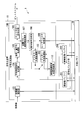
- FIG. 2 is a diagram showing a configuration example of the reference image acquisition position determination unit 110.
- the reference image acquisition position determination unit 110 includes a motion vector result storage unit 401, a position change amount derivation unit 402, and a reference position determination unit 403.
- the motion vector result storage unit 401 acquires motion vector information from the inter prediction processing unit 103.
- the motion vector result storage unit 401 sequentially stores the acquired motion vector information in the motion vector result storage unit 401.
- the motion vector result storage unit 401 acquires the analysis start position parameter representing a fixed value as one of the analysis parameters.
- the motion vector result storage unit 401 uses the position of the block to be coded during the coding process as a reference, from the coded block at the position one or more (fixed value) before, one block before.
- the motion vector information for each coding block up to the coding block at the position is stored.
- the position change amount derivation unit 402 acquires, from the motion vector result storage unit 401, one or more pieces of motion vector information of a coded block that has already been coded. That is, the position change amount derivation unit 402 acquires past motion vector information from the motion vector result storage unit 401.
- the position change amount deriving unit 402 calculates the vertical component amount (motion amount) of the motion vector in the encoded block based on the one or more analysis parameters and the motion vector given by the designer or the like. To analyze. The position change amount derivation unit 402 derives a representative value of the vertical component amount of the motion vector based on the analysis result of the vertical component amount of the motion vector. The position change amount derivation unit 402, based on the representative value of the vertical component amount of the motion vector, stores the area of the reference image data (hereinafter referred to as “reference image area”) at each position in the reference image frame. Position change amount (hopping amount) is determined.
- the reference position determination unit 403 acquires the position change amount information of the reference image area from the position change amount derivation unit 402.
- the reference position determination unit 403 determines the position of the area of the reference image data stored in the reference image buffer 202 among the positions in the reference image frame, based on the position change amount information.
- the reference position determination unit 403 outputs the position information of the area of the reference image data stored in the reference image buffer 202 to the reference image buffer 202 as reference image acquisition position information.
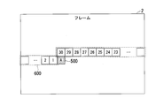
- FIG. 3 is a diagram showing an example of stored reference image data.
- the value of the analysis start position parameter is 30 as an example.
- the position vector of the search center for the coding target block is constant between the coding target frame and the reference image frame.
- the reference image frame is displayed on the entire surface of the encoding target frame 2 shown in each drawing of the embodiment so that the coordinates of the encoding target frame 2 and the coordinates of the reference image frame match. Are stacked.
- the horizontal width of the encoding target frame 2 is 1920 pixels as an example.
- the encoding target frame 2 includes a plurality of encoding blocks.
- the size of the coding block is, for example, 64 ⁇ 64 pixels.
- the motion vector result storage unit 401 stores motion vector information for each coding block from the coding block “1” to the coding block “30”.
- the motion vector result storage unit 401 changes the coding target block 500 “A” from the coding block “1” to the left of the coding target block 500 “A” that is the coding block being coded.
- the motion vector information is stored for each coding block up to the coding block “30” immediately above.
- the motion vector result storage unit 401 may store the motion vector information for each coded coded block that belongs to the line immediately preceding the line to which the coding target block 500 “A” belongs. ..
- the storage target block group 600 is a target coding block group in which motion vector information is stored.
- the motion vector result storage unit 401 obtains the final motion vector from the coding block that is the fixed value before the fixed value represented by the analysis start position parameter with reference to the position of the coding target block 500 “A”. The motion vector information of each coded block up to the latest coded block is stored.
- the motion vector result storage unit 401 deletes the oldest motion vector information stored in the reference image buffer 202 each time the coding of the current block is completed.
- the motion vector result storage unit 401 updates the internal buffer of the motion vector result storage unit 401 by newly storing the newest motion vector in the motion vector search process in the motion vector result storage unit 401.
- the position change amount derivation unit 402 acquires, from the motion vector result storage unit 401, a plurality of pieces of motion vector information of a coded block that has already been coded.
- the acquired motion vector information is specified using two parameters, an analysis start position parameter and an analysis end position parameter.
- the position change amount derivation unit 402 uses the position of the encoding target block 500 “A” as a reference, and the code block preceding by a fixed value represented by the analysis start position parameter by the fixed value represented by the analysis end position parameter. Each motion vector information up to the quantized block is acquired.
- the position change amount derivation unit 402 sets each acquired motion vector information as a motion vector to be analyzed.
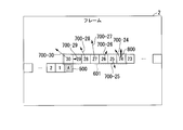
- FIG. 4 is a diagram showing an example of a motion vector to be analyzed.
- the value of the analysis start position parameter is 30 as an example.
- the value of the analysis end position parameter is 24 as an example.
- the position change amount derivation unit 402 analyzes the motion vector information for each coded block from the coded block “24” to the coded block “30”.
- the position change amount derivation unit 402 derives a representative value of the component amount of the motion vector based on the analysis result of the plurality of motion vector information.
- the position change amount derivation unit 402 as an example, derives the representative value of the vertical component amount of the motion vector.
- the position change amount deriving unit 402 determines the position change amount of the reference image area among the respective positions in the reference image frame based on the representative value of the vertical component amount of the motion vector.
- the position change vector 800 is a vector indicating the amount and direction of position change of the reference image area.
- the vertical component amount of the position change vector 800 represents the vertical position change amount of the position where the reference image data is acquired.
- the direction of the position change vector 800 represents the direction of position change of the reference image area.
- the position change amount derivation unit 402 derives the representative value of the component amount of the motion vector so as to be determined based on the magnitude of the vertical movement.
- the representative value of the component amount of the motion vector is, for example, the mode of the component amount of each motion vector.
- the mode value may be, for example, a median value or an average value.
- the vertical component amount of the motion vector 700-27 to be analyzed of the encoded block “27” is the median value of the vertical component amounts of the motion vectors 700-24 to 700-30.
- the position change amount derivation unit 402 determines the value of the position change amount of the reference image area to be equal to the vertical component amount of the motion vector 700-27. That is, the position change amount deriving unit 402 determines the value of the position change amount of the reference image area to be equal to the median value of the vertical component amounts of the motion vectors 700-24 to 700-30.
- the position change amount derivation unit 402 outputs the position change amount information to the reference position determination unit 403.
- the analysis target block group 601 is a coding block group having a motion vector to be analyzed.
- the position change amount derivation unit 402 may derive the representative value of the component amount of the motion vector so as to be determined based on the magnitude of the vertical movement. As a result, the position change amount deriving unit 402 follows the averaged image movement, so that the position change amount excessively follows the sudden (noise-like) movement occurring in the image. It is possible not to.
- the reference position determination unit 403 determines a position, from each position in the reference image frame, from which the reference image data is acquired, based on the position change amount.
- the reference image data stored in the reference image buffer 202 is reference image data in the motion vector search range in the motion search process.
- the center of the rectangular search range in the reference image frame matches the position of the coding target block in the coding target frame.
- the transfer rate of the reference image data transferred from the external memory 20 to the reference image buffer 202 is “(horizontal width of block) ⁇ (vertical width of search range)/ The processing time for one block to be encoded is suppressed.
- the vertical width of the search range affects both the size of the reference image buffer 202 and the transfer rate of the reference image data transferred from the external memory 20 to the reference image buffer 202.
- the width of the search range affects the size (data capacity) of the reference image buffer 202.
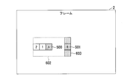
- FIG. 5 is a diagram showing an example of the search range.
- the shape of the search range 602 is a rectangle.
- the size of the search range is 320 ⁇ 192 pixels.
- the search range 602 is a range of “ ⁇ 128 ⁇ 64” pixels including the encoding target block 500 “A”. ..
- the reference image buffer 202 is set to the encoding target during the encoding process of the encoding target block 500 “A”. It is necessary to acquire from the external memory 20 the reference image data of the reference image area of the horizontal width “64” pixels from the 128th pixel to the 192nd pixel from the position of the block 500 “A” to the right (horizontal direction).
- the region including the position where the reference image data is acquired is the reference image region 603.
- the range of the horizontal width (horizontal direction) of the reference image area 603 in the reference image frame is counted rightward from this same position with reference to the same position as the position of the encoding target block 500 “A” in the encoding target frame. It is the range of the horizontal width “64” pixels from the 128th pixel to the 192nd pixel.
- the vertical range of the reference image area 603 in the reference image frame is a range of vertical width “192” pixels including the same position as the position of the encoding target block 500 “A” in the encoding target frame as a reference. Is.
- the center of the reference image area 603 (reference image reading area) and the center of the encoding target block 501 “B” that is the next encoding target block match.
- the reference image data of is acquired from the external memory 20.
- the size of the reference image data stored in the reference image buffer 202 is (320 ⁇ 192) pixels+(64 ⁇ 192) pixels.
- the reference position determination unit 403 transfers the reference image area 603 transferred from the external memory 20 to the reference image buffer 202 during the encoding processing time of one encoding target block (1 encoding target block processing time). The position of is changed in the vertical direction based on the result of the motion search process in the encoded block that has been encoded. Accordingly, the reference position determination unit 403 transfers the position of the search range having the reference image data stored in the reference image buffer 202 among the positions in the reference image frame to the data capacity (buffer size) of the reference image buffer 202. It is possible to adaptively determine in units of coding blocks based on the position change amount information without changing the rate.
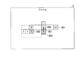
- FIG. 6 is a diagram showing an example of the search range and the acquisition position of the reference image.
- the reference position determination unit 403 determines the motion vector search range and the reference image according to the position change amount determined based on the representative value of the vertical component amount of the motion vector derived in the example shown in FIG. Change the acquisition location information.
- the vertical component amount of the position change vector 800 represents the upward position change amount.
- the reference position determination unit 403 performs the position change in the upward direction according to the position change vector 800 with the position of the block to be coded 501 “B” that is the next block to be coded as a reference.
- the determined position is determined as the center of the reference image area 603 stored in the reference image buffer 202 for encoding the encoding target block 501 “B”.
- the reference image buffer 202 acquires, from the external memory 20, the reference image data of the reference image area 603 that has been repositioned by the position relocation amount in the upward direction.
- the range of the analysis target block group 601 is based on the position of the coding block immediately above the coding target block 501 “B”. It is a range of left-right symmetry between three coding blocks in the left direction and three coding blocks in the right direction. Accordingly, the reference position determination unit 403 can sensitively reflect the motion vector in the coding block immediately above the coding target block 501 “B” in the determination of the reference image acquisition position information.
- the analysis start position parameter and the analysis end position parameter are used to change the position of the motion vector of which coding block has been coded and the reference image region that constitutes the search range of the motion vector of the coding target block to be coded next. It is a parameter that indicates whether to reflect.
- the position change amount deriving unit 402 determines the vertical component amount of the plurality of motion vectors. Based on the simple moving average value, the position change amount of the reference image area among the positions in the reference image frame is determined. In this case, as the difference between the value of the analysis start position parameter and the value of the analysis end position parameter is larger, the amount of movement of the image in the time-series encoding target frame 2 for a long period of time determines the position change amount of the reference image region. Reflected in. With this, the position change amount derivation unit 402 can determine the position change amount that represents a smoother movement.
- the position change amount derivation unit 402 may determine a coding block group (analysis target block group) having a motion vector to be analyzed, based on one or more combinations out of a plurality of prepared combinations. For example, the position change amount deriving unit 402 not only analyzes the block group 601 to be analyzed but also includes a plurality of coding blocks on the same line in the left direction of the coding target block 501 “B” (in FIG. 6, for example, the coding block “ 2”, the coding block “1”, and the coding block “A”) may be a coding block group (analysis target block group) having a motion vector to be analyzed.
- the position change amount deriving unit 402 reflects the analysis result of each motion vector of both the coding block on the upper side of the coding target block and the block on the left side of the coding target block in the position change of the reference image region. It is possible to
- the reference position determination unit 403 changes the reference image acquisition position information according to the position change amount determined based on the derived representative value of the vertical component amount of the motion vector.
- the external memory 20 stores the reference image data in the external memory 20 based on the address of each set of a plurality of pixel data included in the reference image data.
- the reference position determination unit 403 may change the reference image acquisition position in the vertical direction according to the method of storing the reference image data in the external memory 20.
- the reference position determination unit 403 changes the value of the position change amount determined by the position change amount derivation unit 402 to a predetermined integer multiple (for example, a multiple of 4). Good.
- the reference position determination unit 403 outputs the changed position change amount information to the reference image buffer 202.
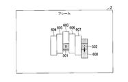
- FIG. 7 is a diagram showing an example of each reference image area in which reference image data is stored in the reference image buffer 202.
- the reference image areas 603 to 607 are a search range of the motion vector of the encoding target block 501 “B”.
- the reference image buffer 202 stores the reference image areas 603 to 607. Each reference image data is stored.
- the search range of (320 ⁇ 192) pixels is composed of the reference image areas 603 to 607. As shown in FIG. 7, the shape of the search range does not have to be rectangular.
- the reference image buffer 202 includes the reference image region included in the search range of the motion vector of the encoding target block 502 “C” that is the next encoding target block.
- the reference image data 608 is acquired from the external memory 20.
- the size of the reference image area 608 is 64 ⁇ 192 pixels.
- the size of the reference image data stored in the reference image buffer 202 is (320 ⁇ 192) pixels+(64 ⁇ 192) pixels.
- the reference position determination unit 403 determines the position of the area (search range) of the reference image data stored in the reference image buffer 202 among the respective positions in the reference image frame as the data capacity (buffer size) of the reference image buffer 202. It is possible to adaptively determine in line units based on the position change amount information without changing the transfer rate and the transfer rate.
- the reference position determination unit 403 outputs the reference image acquisition position information determined based on the position change amount to the reference image buffer 202.
- the reference image buffer 202 derives an address and the like on the external memory 20 corresponding to the reference image acquisition position.
- the reference image buffer 202 outputs a read request signal to the external memory 20 based on the derived address and the like.
- the reference position determination unit 403 determines the position of the reference image area (reference image read area) transferred from the external memory 20 to the reference image buffer 202 based on the position change amount derived for each coding block. I have decided.
- the reference position determination unit 403 may determine the position of the reference image area transferred from the external memory 20 to the reference image buffer 202, based on the position change amount derived for each of the plurality of encoded blocks.
- an “analysis frequency parameter” a parameter indicating how many coding blocks each time the analysis result of the motion vector analyzed once is reflected in the position change of the reference image area (search range) is called an “analysis frequency parameter”.
- the reference position determination unit 403 transfers the reference image to the reference image buffer 202 from the external memory 20 based on the position change amount derived for each coding block. Determine the location of the area.
- FIG. 8 is a diagram showing an example of the reference image area when the value of the analysis frequency parameter is “3”.
- the larger the value of the analysis frequency parameter the longer the horizontal width of the combination of the plurality of reference image areas (the combination of the reference image areas 603, 606, and 607 in FIG. 8) becomes. Therefore, the search including the combination of the plurality of reference image areas is performed.
- the shape of the range is close to a rectangle.
- the larger the value of the analysis frequency parameter the larger the difference in the position change amount between the combinations of the plurality of reference image regions, and thus the reference image acquisition position is likely to change more greatly.
- the reference position determination unit 403 uses the two parameters, that is, the difference between the analysis start position parameter and the analysis end position parameter and the analysis frequency parameter, to determine a plurality of motion vectors of the encoded block that has been encoded. It is possible to adjust the influence of the information on the position of the reference image area and the position change amount.
- the reference position determination unit 403 may give different weights to the motion vectors of the blocks to be analyzed, which are determined according to the analysis start position parameter and the analysis end position parameter.
- the reference position determination unit 403 may derive the weighted moving average of the vertical component amount of the motion vector based on the weighting coefficient giving the weighting.
- the reference position determination unit 403 may increase the weighting coefficient of the motion vector of the coding block at a position close to the center of the analysis target block group 601, compared with the weighting coefficient of the motion vector of another coding block. For example, in FIG. 4, the reference position determination unit 403 relatively increases the weighting factor of the motion vector 700-27 of the coding block “27”, and sets the weighting coefficient of the motion vector 700 of the coding block “24” and “30”.
- the weighting factor may be relatively small.
- the plurality of pieces of motion vector information of the coded block that has been coded are further reflected in the reference image area of the coded block near the coding target block 501 “B” illustrated in FIG. 6.
- the reference image buffer 202 can store a reference image area that can follow a complicated motion in the encoding target frame.
- FIG. 9 is a diagram showing an example of changing the position of each line.
- the value of the analysis start position parameter is 27 as an example.
- the value of the analysis end position parameter is 1, for example.
- the value of the analysis frequency parameter is 30 as an example.
- the reference position determination unit 403 may change the position of the reference image region on a line-by-line basis according to a predetermined unit parameter.
- the search range 610 includes the right end of the encoding target frame. Therefore, the reference image buffer 202 stores the reference image area 611 included in the search range of the motion vector of the encoding target block 504 “B” belonging to the line next to the line to which the encoding target block 503 “A” belongs.
- the reference image data is acquired from the external memory 20.
- the analysis start position parameter and the analysis end position parameter are devised, so that the analysis target block group 609 moves to the left in one line with reference to the position of the coding target block 503 “A”. It consists of all coding blocks. That is, the analysis target block group 609 includes many coding blocks in one line to which the coding target block 503 “A” belongs.
- the position change amount deriving unit 402 assigns the motion vector information of each coding block of the analysis target block group 609 to the code next to the line to which the coding target block 503 “A” belongs. This can be reflected in the determination of the position change amount of the reference image region 611 included in the search range of the motion vector of the block 504 “B” to be converted.
- the position change amount derivation unit 402 assigns the motion vector information of each coding block of the analysis target block group 609 including almost all the coding blocks in one line to which the coding target block 503 “A” belongs. This can be reflected in the determination of the position change amount of the reference image area 611 included in the search range of the motion vector of the encoding target block 504 “B” belonging to the line next to the existing line.
- the position change amount deriving unit 402 sets the position change vector 801-2 of the reference image region 611 included in the search range of the motion vector of the coding target block 504 “B” to each coding block of the analysis target block group 609. Is made equal to the position change vector 801-1 representing the position change amount determined based on the representative value of the component amount of the motion vector in the vertical direction.
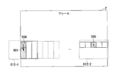
- FIG. 10 is a diagram showing an example of the reference image area.
- the value of the analysis start position parameter is 30 as an example.
- the value of the analysis end position parameter is 24 as an example.
- the value of the analysis frequency parameter is 30 as an example.
- the search range 612 has a rectangular shape.
- the reference position determination unit 403 analyzes these motion vectors for which the search process has been completed.
- the reference position determining unit 403 determines the position change amount of the reference image area included in the search range of the motion vector of each coding target block that belongs to the line next to the line of the coding target block that has become the coded block that has been coded. To decide.
- the reference position determination unit 403 can change the position of the reference image area in line units based on the analysis start position parameter, the analysis end position parameter, and the analysis frequency parameter. For example, when the shape of the search range is limited to a rectangle, the reference position determination unit 403 changes the position of the reference image area on a line-by-line basis. The reference position determination unit 403 can reduce the frequency of changing the position of the reference image area by changing the position of the reference image area on a line-by-line basis.
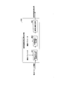
- FIG. 11 is a flowchart showing an operation example of the encoding system 1.
- the motion vector result storage unit 401 (motion vector acquisition unit) acquires a motion vector for each coded block that has been coded (step S101).
- the position change amount deriving unit 402 derives the position change amount of the area of the reference image data (reference image area) stored in the reference image buffer 202 based on the acquired motion vector (step S102).
- the reference position determination unit 403 (reference region determination unit) determines the position of the region of the reference image data used for encoding the encoding target block which is the encoding block next to the encoding target encoding block. , Based on the derived position change amount (step S103).
- the encoding device 10 determines the reference area stored in the reference image buffer.
- the encoding device 10 includes a motion vector result storage unit 401 (motion vector acquisition unit), a position change amount derivation unit 402, and a reference position determination unit 403 (reference area determination unit).
- the motion vector result storage unit 401 acquires a motion vector for each coded block.
- the position change amount deriving unit 402 derives the position change amount of the reference image area (reference area) based on the acquired motion vector.
- the reference position determination unit 403 determines the position of the reference image region (reference region) used for encoding the encoding block that is the next encoding target after the encoded encoding block, based on the amount of position change.
- the encoding device 10 of the first embodiment can suppress the decrease in encoding efficiency even when the buffer stores the reference image data of only a part of the reference image frame.
- the encoding apparatus 10 refers to the reference image frame referred to from the encoding target frame in encoding block units or line units, even when only the reference image data in the search range is stored in the reference image buffer 202. Since the position of the search range including the image area is changed, it is possible to prevent the coding efficiency from decreasing.
- the reference position determination unit 403 determines the position of the search range of the motion vector of the target block to be coded in the reference image frame in real time on a coding block basis. To decide.
- the position in the reference image frame referred to from the encoding target frame that is, the position of the region of the reference image data acquired from the external memory 20 by the reference image buffer 202 is as described with reference to FIG. 6 or 9. May be devised.
- the encoding apparatus 10 suppresses the increase in the data capacity of the reference image buffer and the transfer rate of the reference image data transferred from the external memory 20 to suppress the movement of the object image captured in the encoding target frame. It is possible to follow accurately and improve the coding efficiency.
- the second embodiment is different from the first embodiment in that the reference image acquisition position determination unit determines the position of the reference image region based on the motion vector information, the accumulated difference value, and the block size information.
- the reference image acquisition position determination unit determines the position of the reference image region based on the motion vector information, the accumulated difference value, and the block size information.
- the value such as the accumulated difference value can be an index indicating how correct the motion vector as a result of the motion search process is (the accuracy of the motion vector). Therefore, the position change amount deriving unit 402 may derive the position change amount based on a combination of a plurality of pieces of information other than the motion vector information.
- the reference position determination unit 403 may determine the area of the reference image data stored in the reference image buffer 202 based on the position change amount thus derived.
- a coding tree unit having a size of 64 ⁇ 64 pixels may be further divided into four branches. In this case, even if the number of coding tree units to be analyzed is specified using the analysis start position parameter and the analysis end position parameter, the number of motion vectors acquired by the position change amount derivation unit 402 is Is larger than the number of coding tree units to be analyzed.
- the position change amount deriving unit 402 may derive the position change amount based on the block size information (division information) and the motion vector information in the search result of the motion vector of the encoded block that has been encoded.
- FIG. 12 is a diagram showing a configuration example of the reference image acquisition position determination unit 110.
- the reference image acquisition position determination unit 110 includes a motion vector result storage unit 401, a position change amount derivation unit 402, a reference position determination unit 403, a difference cumulative value storage unit 404, and a block size storage unit 405.
- the motion vector result storage unit 401 uses the position of the block to be coded during the coding process as a reference, from the coded block at the position one or more (fixed value) before, one block before.
- the motion vector information for each coding block up to the coding block at the position is stored.
- the difference accumulated value storage unit 404 acquires, from the inter prediction processing unit 103, the difference accumulated value when the motion vector is used for encoding.
- the cumulative difference value storage unit 404 determines, based on the analysis start position parameter, from the coding block at the position one or more (fixed value) before, with respect to the position of the coding target block being coded, one position before the coding block. The cumulative difference value for each coded block up to the coded block at the position is stored.
- the difference accumulated value storage unit 404 deletes the oldest difference accumulated value stored in the difference accumulated value storage unit 404 from the difference accumulated value storage unit 404 every time the encoding of the target block is completed.
- the difference cumulative value storage unit 404 stores the latest acquired difference cumulative value in the difference cumulative value storage unit 404. In this way, the difference cumulative value storage unit 404 updates the data stored in the difference cumulative value storage unit 404.
- the block size storage unit 405 acquires, from the inter prediction processing unit 103, block size information that is information indicating what size the coding block is divided into when the motion vector is used for coding.
- the block size information for each coding block up to the coding block at the position is stored.
- the block size storage unit 405 deletes the oldest block size information stored in the block size storage unit 405 from the block size storage unit 405 each time the encoding of the target block is completed.
- the block size storage unit 405 stores the acquired newest block size information in the block size storage unit 405. In this way, the block size storage unit 405 updates the data stored in the block size storage unit 405.
- the position change amount derivation unit 402 acquires, from the motion vector result storage unit 401, one or more pieces of motion vector information of a coded block that has already been coded.
- the position change amount deriving unit 402 acquires from the difference cumulative value storage unit 404 one or more difference cumulative values of the coded blocks that have been coded.
- the position change amount derivation unit 402 acquires, from the block size storage unit 405, one or more block size information of the coded blocks that have been coded.
- the position change amount derivation unit 402 uses the one or more analysis parameters, the motion vector, the accumulated difference value, and the block size information provided by the designer, etc., in the vertical direction of the motion vector in the encoded block.
- the component amount (movement amount) of is analyzed.
- FIG. 13 is a diagram showing an example of a coding block.
- the value of the analysis start position parameter is 30 as an example.
- the value of the analysis end position parameter is 24 as an example.
- the analysis target block group 613 is seven coding blocks (coding tree unit) from the coding block “24” to the coding block “30” having the motion vector to be analyzed.
- the coding block “24”, the coding block “26”, and the coding block “29” are divided.
- the number of pieces of motion vector information to be analyzed, the number of accumulated difference values, and the number of block size information that is the size information of the encoded block are 19 pieces each.
- the position change amount deriving unit 402 calculates the block size weighting coefficient “E i ”of the i-th encoded block, the weighting coefficient “F i ”of the difference accumulated value of the i-th encoded block, and the i-th encoded block. It has three types of weighting factors including the initial weighting factor “G i ”of the block.
- the position change amount determined based on the representative value of the vertical component amount of the motion vector is calculated by using the vertical component amount (motion amount) “V yi ” of the motion vector of the i-th coded block, It is expressed as (1).
- the block size weighting factor “E i ”shown in equation (1) is set to a value corresponding to the area of the i-th encoded block, for example.
- the weighting coefficient “F i ”of the cumulative difference value is set to a smaller value as the cumulative difference value is larger. That is, the weighting factor “F i ”of the difference accumulated value is set to a smaller value as the accuracy of the searched motion vector is lower. Accordingly, the position change amount deriving unit 402 can derive the position change amount according to the accuracy of the searched motion vector.
- FIG. 14 is a diagram showing an example of a weighting coefficient table for accumulated difference values.
- the difference cumulative value weighting coefficient table the average error per pixel is associated with the difference cumulative value weighting coefficient.
- the position change amount derivation unit 402 acquires the weighting coefficient table of the difference cumulative value.
- the position change amount derivation unit 402 may store in advance a weighting coefficient table for accumulated difference values.
- the position change amount deriving unit 402 derives a normalized difference cumulative value based on the acquired difference cumulative value and block size information. That is, the position change amount deriving unit 402 derives the average error per pixel, which is the result of dividing the difference cumulative value by the block size.
- the position change amount deriving unit 402 acquires, from the difference accumulation value weight coefficient table, the “difference accumulation value weight coefficient” associated with the “average error per pixel” in the difference accumulation value weight coefficient table.
- the initial weighting factor “G i ”shown in equation (1) is the motion of each of the coded blocks in the plurality of coded blocks of the analysis target block when the block size and the difference cumulative value of the coded blocks are equal. It represents the initial value of vector weighting.
- the position change amount derivation unit 402 determines the component amount of the vertical motion vector based on the initial weighting coefficient “G i ”, according to the block size of the encoded block and the difference cumulative value (motion vector search accuracy). It is possible to derive a representative value.
- the position change amount deriving unit 402 derives the weighted moving average of the vertical component amounts of the motion vector.
- the position change amount The deriving unit 402 derives a simple moving average of vertical component amounts of the motion vector.
- the reference position determination unit 403 acquires the position change amount information of the reference image area from the position change amount derivation unit 402.
- the reference position determination unit 403 determines the position of the area of the reference image data stored in the reference image buffer 202 among the positions in the reference image frame, based on the position change amount information.
- the reference position determination unit 403 outputs the position information of the area of the reference image data stored in the reference image buffer 202 to the reference image buffer 202 as reference image acquisition position information.
- the encoding device 10 (reference area determination device) of the second embodiment includes the position change amount derivation unit 402.
- the position change amount deriving unit 402 derives the position change amount of the reference image area (search range) based on the acquired motion vector and block size information (division information) of the coded block that has been coded.
- the position change amount deriving unit 402 may derive the position change amount according to the accuracy (for example, difference accumulated value) of the acquired motion vector.
- the encoding device 10 can suppress the decrease in encoding efficiency even when the buffer stores the reference image data of only a part of the reference image frame.
- the encoding device 10 can change the vertical position of the search range in units of encoding blocks without increasing the buffer size and the transfer rate of the reference image data transferred from the external memory 20. is there.
- the encoding apparatus 10 changes the position of the search range of the motion vector of the next encoding target block, which is the encoding target, in units of encoding blocks according to the search result of the motion vector of the encoded block that has been encoded. It is possible to Since the shape of the search range is not limited to a rectangle on the assumption that the area of the search range is constant, the encoding device 10 uses the reference image buffer 202 having a low transfer rate of reference image data and a small buffer size to perform encoding. It is possible to improve the conversion efficiency.
- the encoding device 10 includes a reference image buffer 202 and a reference image acquisition position determination unit 110.
- the reference image buffer 202 stores a reference image stored in the external memory 20 when performing motion vector search processing and pixel value prediction on an input image by using temporal correlation with the reference image in moving image encoding. Is temporarily stored for the motion vector search process.
- the reference image acquisition position determination unit 110 includes a motion vector result storage unit 401, a position change amount derivation unit 402, and a reference position determination unit 403.
- the motion vector result storage unit 401 acquires an analysis start position parameter that can be set to an arbitrary natural number.
- the reference image acquisition position determination unit 110 specifies a start block and a storage end block.
- the start block is a macroblock or a coding block that is a macroblock or a coding tree unit that is performing a motion vector search process at a certain time.
- ⁇ It is a tree unit.
- the storage end block is a block (macro block or CTU) whose motion vector search process has been completed and whose encoding process is closest to the encoding target block.
- the motion vector result storage unit 401 stores the motion search result in the internal buffer of the motion vector result storage unit 401 for the block to be stored.
- the storage target block group is all macroblocks or coding tree units located from the start block to the storage end block in the order of encoding processing.
- the motion vector result storage unit 401 updates the data stored in the buffer by updating the storage target block group each time the coding target block advances by one macro block or CTU.
- the position change amount derivation unit 402 (vertical hopping amount analysis unit) acquires an analysis end position parameter and an analysis frequency parameter that can be set to arbitrary natural numbers.
- the position change amount derivation unit 402 determines the analysis end block.
- the analysis end block is a macro block or CTU located before the encoding target block by the number of analysis end position parameters.
- the position change amount derivation unit 402 acquires, from the buffer of the motion vector result storage unit 401, an analysis target motion search result that is a motion search result of the analysis target block group for the analysis target block group.
- the analysis target block group is all macroblocks or CTUs located from the start block to the analysis end block in the order of encoding processing.
- the position change amount deriving unit 402 is a typical vertical motion amount in the past based on the analysis of the motion search result of the analysis target at a timing of once for each macro block or CTU of the number of analysis frequency parameters.
- the position change amount (hopping amount) in the vertical direction is determined and updated.
- the reference position determination unit 403 acquires the vertical position change amount from the vertical position change amount analysis unit.
- the reference position determination unit 403 acquires a search vertical width parameter corresponding to the vertical width of the search range of the motion search and a search horizontal width parameter corresponding to the horizontal width of the search range of the motion search.
- the reference position determination unit 403 determines the position of the reference image area in the rectangular range of “search vertical width parameter ⁇ (horizontal width of encoding target block)” for each macroblock or coding tree unit.
- the reference position determination unit 403 sets, as a reference point, a position advanced from the encoding target block in the processing order by the number of pixels of the search width parameter, and a position distant from the reference point by a position change amount in the vertical direction is defined as a rectangular range.
- the position of the reference image area is determined.
- the reference image buffer 202 acquires the position of the reference image area in the rectangular range from the reference position determination unit 403.
- the reference image buffer 202 derives an address on the external memory 20 corresponding to the data of the reference image area in the rectangular range.
- the reference image buffer 202 sends a read request to the external memory 20.
- the reference image buffer 202 temporarily stores reference image data transferred from the external memory 20 in response to a read request.
- the motion vector result storage unit 401 stores the motion vector information of the past motion search result as the analysis target motion search result for all macro blocks or CTUs corresponding to the analysis target block group.
- the position change amount derivation unit 402 derives an average value or a median value of the values in the vertical direction in the motion vector of the analysis target block group.
- the position change amount deriving unit 402 makes the value of the vertical position change amount equal to the derived average value or median value.
- the position change amount derivation unit 402 acquires a relative distance weighting coefficient.
- the relative distance weighting coefficient is a parameter that is uniquely determined according to how far the macroblock or the coding tree unit is away from the block to be coded in the processing order.
- the position change amount derivation unit 402 derives the weighted average value based on the relative distance weighting coefficient (weighted average weighting of the vertical value of the motion vector) and the vertical value of the motion vector.
- the position change amount deriving unit 402 makes the value of the vertical position change amount equal to the weighted average value.
- the motion vector result storage unit 401 stores a block area value indicating how much area each of the motion vectors has for each of the macroblocks or coding tree units corresponding to the analysis target block group.
- the motion vector information is stored as the analysis target motion search result.
- the position change amount derivation unit 402 calculates the weighted average based on the block area value (weighted average weighting of the vertical values of the motion vector corresponding to each block area information) and the vertical value of the motion vector. Derive the value.
- the position change amount derivation unit 402 makes the value of the vertical position change amount equal to the weighted average value.
- the motion vector result storage unit 401 sets, as an analysis target motion search result, a cumulative difference value and motion vector information indicating motion search error in each motion vector for all macro blocks or CTUs corresponding to the analysis target block group. save.
- the position change amount derivation unit 402 acquires the weighting coefficient table of the difference cumulative value.
- the position change amount derivation unit 402 extracts the weighting coefficient of the difference accumulated value associated with the magnitude of the difference accumulated value from the weighting coefficient table of the difference accumulated value. That is, the motion vector result storage unit 401 converts each of the difference cumulative values of the analysis target block group into the weight coefficient of the difference cumulative value using the weight coefficient table of the difference cumulative value.
- the position change amount derivation unit 402 based on the weighting coefficient of the accumulated difference value (weighted average weighting for the vertical value of the motion vector corresponding to each of the block area information) and the vertical value of the motion vector, , Derive the weighted average value.
- the position change amount derivation unit 402 makes the value of the vertical position change amount equal to the weighted average value.
- the motion vector result storage unit 401 stores the motion vector information, the block area value, and the accumulated difference value as the analysis target motion search result for all macro blocks or coding tree units corresponding to the analysis target block group.
- the position change amount derivation unit 402 converts each of the difference cumulative values of the analysis target block group into the weight coefficient of the difference cumulative value using the weight coefficient table of the difference cumulative value.
- the position change amount deriving unit 402 calculates the result of multiplication of the weighting coefficient of the accumulated difference value, the block area value, and the relative distance weighting coefficient (the weighted average weighting result of each vertical value of the motion vector) and the motion.
- the weighted average value is derived regardless of the vertical value of the vector.
- the position change amount derivation unit 402 makes the value of the vertical position change amount equal to the weighted average value.
- the reference area determination device in the above-described embodiment may be realized by a computer.
- the program for realizing this function may be recorded in a computer-readable recording medium, and the program recorded in this recording medium may be read by a computer system and executed.
- the “computer system” mentioned here includes an OS and hardware such as peripheral devices.
- the “computer-readable recording medium” refers to a portable medium such as a flexible disk, a magneto-optical disk, a ROM, a CD-ROM, or a storage device such as a hard disk built in a computer system.
- the "computer-readable recording medium” means to hold a program dynamically for a short time like a communication line when transmitting the program through a network such as the Internet or a communication line such as a telephone line.
- a volatile memory inside a computer system that serves as a server or a client in that case may hold a program for a certain period of time.
- the program may be for realizing a part of the above-mentioned functions, or may be a program for realizing the above-mentioned functions in combination with a program already recorded in a computer system, It may be realized using a programmable logic device such as FPGA (Field Programmable Gate Array).
- the present invention can be applied to an encoding device that encodes moving images and the like.
- 1... Encoding system 2... Encoding target frame, 10... Encoding device, 20... External memory, 101... Original image shaping section, 102... Intra prediction processing section, 103... Inter prediction processing section, 104... Prediction residual Signal generation unit, 105... Transform/quantization processing unit, 106... Entropy coding unit, 107... Inverse quantization/inverse transformation processing unit, 108... Decoded signal generation unit, 109... Loop filter processing unit, 110... Reference image acquisition Position determination unit, 200... Encoding buffer unit, 201... Original image buffer, 202... Reference image buffer, 401... Motion vector result storage unit, 402... Position change amount derivation unit, 403... Reference position determination unit, 404... Difference accumulation Value storage unit, 405... Block size storage unit, 500 to 505...
- Encoding target block 600... Storage target block group, 601... Analysis target block group, 602... Search range, 603 to 608... Reference image area, 609... Analysis Target block group, 610... Search range, 611... Reference image area, 612... Search range, 613... Analysis target block group, 700... Motion vector, 800-801... Position change vector
Landscapes
- Engineering & Computer Science (AREA)
- Multimedia (AREA)
- Signal Processing (AREA)
- Compression Or Coding Systems Of Tv Signals (AREA)
Abstract
参照領域決定装置は、参照画像バッファに格納される参照領域を決定する参照領域決定装置であって、符号化済みのブロックごとに動きベクトルを取得する動きベクトル取得部と、取得された動きベクトルに基づいて、参照領域の位置変更量を導出する位置変更量導出部と、符号化済みのブロックの次の符号化対象のブロックの符号化に用いられる参照領域の位置を、位置変更量に基づいて決定する参照領域決定部とを備える。
Description
本発明は、参照領域決定装置及びプログラムに関する。
MPEG(Moving Picture Experts Group)-2、MPEG-4、MPEG-4/AVC(Advanced Video Coding)等の動画像符号化規格がある。HEVC(High Efficiency Video Coding)は、今後の普及が見込まれている次世代の動画像符号化規格である。
HEVCの符号化効率は、従来の符号化方式であるMPEG-4/AVCの符号化効率の約2倍である。符号化効率の向上に伴い、4K(3840画素×2160ライン)又は8K(7680画素×4320ライン)等の高い空間解像度の動画像も、符号化対象とされるようになった。階層的符号化処理では、符号化ブロックの様々なサイズのうち、符号化効率が最も高くなるサイズが選択されることによって、符号化対象フレームにおける符号化対象の符号化ブロック(以下「符号化対象ブロック」という。)の符号化効率が向上する。
階層的符号化処理では、符号化装置は、符号化対象フレームと参照画像フレームとの間の動きベクトルを探索、推定及び補償するフレーム間符号化を実行する。以下、参照画像フレームにおける参照画像と符号化対象ブロックの画像との画素単位の差分の累積値を「差分累積値」という。符号化装置の探索モジュールは、参照画像フレームにおいて差分累積値等が最も小さくなる位置(座標)を示す動きベクトルを、様々なサイズの符号化対象ブロックごとに階層的に探索することによって、動きベクトルを推定する。以下、参照画像フレームの各画素の画素値を表すデータを「参照画像データ」という。
階層的符号化処理では、非常に多くの参照画像データが必要とされる。全ての参照画像フレームに相当する全ての参照画像データのデータサイズは非常に大きいので、LSI(Large Scale Integration)は、LSIの内部に設けられた参照画像バッファに、全ての参照画像データのうちの一部しか格納することができない。このため、全ての参照画像データを外部メモリが格納しておく必要がある。外部メモリのインタフェースにおけるデータ転送速度には制限がある。外部メモリ内の全ての参照画像データのうちフレーム間符号化が実行される際に必要となる特定の参照画像データをリアルタイムに探索モジュールが読み込むために、LSIは、外部メモリから転送された参照画像データを、LSIの内部に設けられた参照画像バッファに一時的に格納する。LSIは、参照画像バッファに一時的に格納された参照画像データを、探索モジュールに供給する。
外部メモリから転送される参照画像データの転送レートを抑えるため、符号化対象フレームの横幅分(ライン分)の参照画像データを格納する参照画像バッファが提案されている(非特許文献1)。HEVC等の符号化規格では、符号化対象ブロックは、ラスタスキャン順に符号化される。動きベクトルの探索範囲は、参照画像フレームにおける所定位置を中心とする範囲である。動きベクトルの探索範囲の形状は、矩形である。
符号化対象フレームにおける符号化対象ブロックの位置と、参照画像フレームにおける動きベクトルの探索中心位置との位置関係が一定であるという条件で、探索モジュールは動きベクトルの探索処理を実行する場合がある。この場合、「(符号化対象フレームの横幅)×(探索範囲の縦幅)」分の参照画像データをバッファデータとして参照画像バッファが格納することによって、同一ライン上で符号化対象ブロックが右(水平方向)の符号化対象ブロックに更新されても、参照画像バッファはバッファデータを更新する必要がない。複数の符号化ブロックから構成された1本のラインにおいて符号化対象ブロックの符号化処理が実行される間に、「(符号化対象フレームの横幅)×(探索範囲の縦幅)」分の新たなデータを、外部メモリは参照画像バッファに転送する。このため、外部メモリから参照画像バッファに転送される参照画像データの転送レートは、「(符号化対象ブロックの横幅)×(符号化対象ブロックの縦幅)/1符号化対象ブロック処理時間」に抑えられる。
バッファサイズは、「(符号化対象フレームの横幅)×(探索範囲の縦幅)」にほぼ等しい。このため、4K又は8K等の高い空間解像度の動画像が符号化される場合、参照画像バッファのサイズが大きくなることによって、LSIの規模、サイズ及び電力が悪化する場合がある。
参照画像バッファのサイズを抑える方法として、符号化処理中の符号化対象ブロックの動きベクトルの探索範囲の参照画像データのみを参照画像バッファが常に格納する方法が考えられる。符号化対象ブロックから一定距離の位置を中心とした探索範囲の形状が矩形であり、符号化処理中の符号化対象ブロックが同一ラインの右方向に更新される場合、各符号化ブロックの動きベクトルの探索範囲の重複面積は広くなる。符号化処理中の符号化対象ブロックが同一ライン上方向に更新されたことによって転送が新たに必要となる参照画像データは、探索範囲の右側に位置している符号化ブロックの横幅分の参照画像データのみである。この場合、参照画像バッファのサイズは、「(探索範囲の横幅)×(探索範囲の縦幅)」にほぼ等しい。外部メモリから参照画像バッファに転送される参照画像データの転送レートは、「(符号化ブロックの横幅)×(探索範囲の縦幅)/1符号化対象ブロック処理時間」に抑えられる。これによって、4K又は8K等の高い空間解像度の動画像の転送は、現実的な転送レートで可能である。
Takayuki Onishi, Takashi Sano, Yukikuni Nishida, Kazuya Yokohari, Jia Su, Ken Nakamura, Koyo Nitta, Kimiko Kawashima, Jun Okamoto, Naoki Ono, Ritsu Kusaba, Atsushi Sagata, Hiroe Iwasaki, Mitsuo Ikeda, and Atsushi Shimizu, "Single-chip 4K 60 fps 4:2:2 HEVC video encoder LSI with 8K scalability," Symposium on VLSI Circuits Digest of Technical Papers, C54-C55, 2015.
しかしながら、符号化処理中の符号化対象ブロックの動きベクトルの探索範囲の参照画像データのみを参照画像バッファが常に格納する場合、いくつかの条件が満たされる必要がある。具体的には、探索範囲の形状が矩形であり、符号化対象ブロックに対する探索中心の位置ベクトルが符号化対象フレーム及び参照画像フレームの間で一定であり、かつ、その位置ベクトルが符号化対象フレームの符号化処理の開始前に決定済みである、という条件が満たされる必要がある。
同一の符号化対象フレーム内であっても符号化ブロックごとに様々な動きベクトルが生じ得る。このため、符号化ブロックに対する探索中心の位置ベクトルが符号化対象フレーム及び参照画像フレームの間で一定であるという条件が満たされた場合、符号化ブロックによっては、差分累積値が最小となる動きベクトル(最良の動きベクトル)が、参照画像バッファには格納されていない参照画像データの領域を示す場合がある。この場合、符号量の増加と符号化効率の低下とが発生し得る。
参照画像バッファに格納されている参照画像データの領域を、最良の動きベクトルがなるべく示すようにするには、参照画像バッファに格納される参照画像データの探索範囲が広くなるので、参照画像バッファのデータ容量のサイズと外部メモリから転送される参照画像データの転送レートとが増大する。このため、動き探索処理が実行される探索中心の位置は、符号化対象フレーム単位よりも細かい粒度(例えば、符号化ブロック単位、符号化ブロックのライン単位)で決定されるべきである。参照画像フレームの横幅分の参照画像データを参照画像バッファが格納している場合、参照画像フレームの水平方向の全ての参照画像データが参照画像バッファに格納されている。これによって、符号化装置の探索モジュールは、動きベクトルの探索中心の位置を、参照画像フレームにおいて水平方向に柔軟に位置変更させることが可能である。また、符号化装置の探索モジュールは、参照画像フレームにおける動きベクトルの探索範囲の水平方向の位置変更量(ホッピング量)を、符号化ブロック単位で決定することが可能である。
しかしながら、従来の符号化装置(参照領域決定装置)は、参照画像フレームの一部分のみの参照画像データをバッファが格納する場合、符号化効率の低下を抑止することができない場合がある。
上記事情に鑑み、本発明は、参照画像フレームの一部分のみの参照画像データをバッファが格納する場合でも、符号化効率の低下を抑止することが可能である参照領域決定装置及びプログラムを提供することを目的としている。
本発明の一態様は、参照画像バッファに格納される参照領域を決定する参照領域決定装置であって、符号化済みのブロックごとに動きベクトルを取得する動きベクトル取得部と、取得された動きベクトルに基づいて、前記参照領域の位置変更量を導出する位置変更量導出部と、前記符号化済みのブロックの次の符号化対象のブロックの符号化に用いられる前記参照領域の位置を、前記位置変更量に基づいて決定する参照領域決定部と、を備える参照領域決定装置である。
本発明の一態様は、上記の参照領域決定装置であって、前記動きベクトル取得部は、前記符号化対象のブロックが属するラインの1本前のラインに属する前記符号化済みのブロックごとに、前記動きベクトルを取得する。
本発明の一態様は、上記の参照領域決定装置であって、前記位置変更量導出部は、取得された前記動きベクトルの垂直方向の成分量の代表値に基づいて、垂直方向の前記位置変更量を導出する。
本発明の一態様は、上記の参照領域決定装置であって、前記代表値は、取得された前記動きベクトルの垂直方向の成分量の中央値又は平均値である。
本発明の一態様は、上記の参照領域決定装置であって、前記位置変更量導出部は、取得された前記動きベクトルと前記符号化済みのブロックの分割情報とに基づいて、前記位置変更量を導出する。
本発明の一態様は、上記の参照領域決定装置であって、前記位置変更量導出部は、取得された前記動きベクトルの精度に応じて前記位置変更量を導出する。
本発明の一態様は、上記の参照領域決定装置としてコンピュータを機能させるためのプログラムである。
本発明により、参照画像フレームの一部分のみの参照画像データをバッファが格納する場合でも、符号化効率の低下を抑止することが可能である。
本発明の実施形態について、図面を参照して詳細に説明する。
以下、符号化ブロックは、「MPEG-2」又は「H.264/AVC」規格では、マクロブロックである。符号化ブロックは、HEVCでは、コーディング・ユニット(Coding Unit: CU)、又は、プレディクション・ユニット(Prediction Unit: PU)である。コーディング・ユニットは、コーディング・ツリー・ユニット(Coding Tree Unit: CTU)を構成する。
以下、符号化ブロックは、「MPEG-2」又は「H.264/AVC」規格では、マクロブロックである。符号化ブロックは、HEVCでは、コーディング・ユニット(Coding Unit: CU)、又は、プレディクション・ユニット(Prediction Unit: PU)である。コーディング・ユニットは、コーディング・ツリー・ユニット(Coding Tree Unit: CTU)を構成する。
(第1実施形態)
図1は、符号化システム1の構成例を示す図である。符号化システム1は、符号化装置10と、外部メモリ20とを備える。符号化装置10は、動画像を符号化する際に参照画像バッファに格納される参照画像データの領域(参照領域)を決定する装置(参照領域決定装置)である。符号化装置10は、外部メモリ20に接続される。符号化装置10は、原画像データ(動画像のフレーム)及び参照画像データを、外部メモリ20に記録する。
符号化装置10は、記録された原画像データ及び参照画像データを、外部メモリ20から取得する。符号化装置10は、指定されたパラメータと参照画像データとに基づいて、原画像データを符号化する。
図1は、符号化システム1の構成例を示す図である。符号化システム1は、符号化装置10と、外部メモリ20とを備える。符号化装置10は、動画像を符号化する際に参照画像バッファに格納される参照画像データの領域(参照領域)を決定する装置(参照領域決定装置)である。符号化装置10は、外部メモリ20に接続される。符号化装置10は、原画像データ(動画像のフレーム)及び参照画像データを、外部メモリ20に記録する。
符号化装置10は、記録された原画像データ及び参照画像データを、外部メモリ20から取得する。符号化装置10は、指定されたパラメータと参照画像データとに基づいて、原画像データを符号化する。
外部メモリ20は、例えばDRAM(Dynamic Random Access Memory)などの揮発性の記録媒体である。外部メモリ20は、例えばフラッシュメモリなどの不揮発性の記録媒体(非一時的な記録媒体)でもよい。外部メモリ20は、例えば、整形された原画像データを記憶する。
以下では、符号化装置10は、一例として、「H.264/AVC」又はHEVC等の動画像符号化処理を実行する。符号化装置10は、符号化処理を符号化ブロック単位で実行する。
符号化装置10の構成例の詳細を説明する。
符号化装置10は、符号化処理部100と、符号化バッファ部200とを備える。符号化処理部100は、原画像整形部101と、イントラ予測処理部102と、インター予測処理部103と、予測残差信号生成部104と、変換・量子化処理部105と、エントロピー符号化部106と、逆量子化・逆変換処理部107と、復号信号生成部108と、ループフィルタ処理部109と、参照画像取得位置決定部110とを備える。
符号化装置10は、符号化処理部100と、符号化バッファ部200とを備える。符号化処理部100は、原画像整形部101と、イントラ予測処理部102と、インター予測処理部103と、予測残差信号生成部104と、変換・量子化処理部105と、エントロピー符号化部106と、逆量子化・逆変換処理部107と、復号信号生成部108と、ループフィルタ処理部109と、参照画像取得位置決定部110とを備える。
符号化装置10の各機能部のうち一部又は全部は、例えば、LSI等のハードウェアを用いて実現される。符号化装置10の各機能部のうちの一部又は全部は、CPU(Central Processing Unit)等のプロセッサが、記憶部に記憶されたプログラムを実行することにより、ソフトウェアとして実現されてもよい。
符号化バッファ部200は、原画像バッファ201と、参照画像バッファ202とを備える。符号化バッファ部200は、例えばSRAM(Static Random Access Memory)などの揮発性の記録媒体である。符号化バッファ部200は、例えば、原画像データ、参照画像データを記憶する。
符号化処理部100の構成例の詳細を説明する。
原画像整形部101は、原画像データ(動画像のフレーム)を、ラスタスキャン順で取得する。原画像整形部101は、原画像データを符号化ブロック単位に整形する。原画像整形部101は、符号化ブロック単位の原画像データを、外部メモリ20に出力する。
原画像整形部101は、原画像データ(動画像のフレーム)を、ラスタスキャン順で取得する。原画像整形部101は、原画像データを符号化ブロック単位に整形する。原画像整形部101は、符号化ブロック単位の原画像データを、外部メモリ20に出力する。
イントラ予測処理部102は、復号信号を復号信号生成部108から取得する。イントラ予測処理部102は、復号信号の対象フレームに対して、イントラ予測を実行する。
インター予測処理部103は、符号化ブロック単位の原画像データを、原画像バッファ201から取得する。インター予測処理部103は、フィルタリング処理後の復号信号を、参照画像信号として、参照画像バッファ202から取得する。インター予測処理部103は、フレームの間の動き探索処理を実行する。
予測残差信号生成部104は、符号化ブロック単位の原画像データを、原画像バッファ201から取得する。予測残差信号生成部104は、予測信号をイントラ予測処理部102又はインター予測処理部103から取得する。予測残差信号生成部104が予測信号をイントラ予測処理部102から取得する場合、予測信号は、イントラ予測の結果を表す情報を含む。予測残差信号生成部104が予測信号をインター予測処理部103から取得する場合、予測信号は、インター予測の結果を表す情報を含む。予測残差信号生成部104は、原画像データと予測信号との差分を、予測残差信号として変換・量子化処理部105に出力する。
変換・量子化処理部105は、離散コサイン変換等の直交変換を予測残差信号に対して実行する。変換・量子化処理部105は、変換係数を量子化する。変換・量子化処理部105は、量子化された変換係数を、エントロピー符号化部106と逆量子化・逆変換処理部107とに出力する。
エントロピー符号化部106は、量子化された変換係数をエントロピー符号化する。エントロピー符号化部106は、エントロピー符号化された変換係数のビットストリームを、復号装置等である外部装置に出力する。このように、符号化装置10は、動き探索処理における探索結果を、復号装置等である外部装置に送信する。
逆量子化・逆変換処理部107は、量子化された変換係数を、変換・量子化処理部105から取得する。逆量子化・逆変換処理部107は、量子化された変換係数に対して、逆量子化及び逆直交変換処理を実行する。逆量子化・逆変換処理部107は、逆量子化及び逆直交変換処理の結果である予測残差復号信号を、復号信号生成部108に出力する。
復号信号生成部108は、予測信号をイントラ予測処理部102又はインター予測処理部103から取得する。復号信号生成部108は、予測残差復号信号と予測信号とを加算することによって、符号化された対象ブロックの復号信号を生成する。
ループフィルタ処理部109は、符号化歪みが低減されるフィルタリング処理を、復号信号に対して実行する。ループフィルタ処理部109は、フィルタリング処理後の復号信号を、参照画像信号として、外部メモリ20に出力する。
参照画像取得位置決定部110は、インター予測による動きベクトルの探索結果を、インター予測処理部103から取得する。参照画像取得位置決定部110は、動きベクトルの探索結果に基づいて、動きベクトル情報等を解析する。参照画像取得位置決定部110は、参照画像フレームにおける各位置のうち、参照画像バッファ202が格納する参照画像データの領域(座標)を、動きベクトル情報等の解析結果に基づいて決定する。参照画像取得位置決定部110は、参照画像バッファ202が格納する参照画像データの領域の位置情報を、参照画像バッファ202に出力する。
原画像バッファ201は、読み出し要求信号(リード要求信号)を、外部メモリ20に出力する。原画像バッファ201は、読み出し要求信号に応じて外部メモリ20から転送された符号化ブロックごとの原画像データを、原画像バッファ201に一時的に格納する。
参照画像バッファ202は、参照画像バッファ202が格納する参照画像データの領域の位置情報を、参照画像取得位置決定部110から取得する。参照画像バッファ202は、参照画像データの領域の位置情報に基づいて、読み出し要求信号を外部メモリ20に出力する。参照画像バッファ202は、読み出し要求信号に応じて外部メモリ20から転送された参照画像データを、参照画像バッファ202に一時的に格納する。このようにして、参照画像バッファ202は、動き探索処理に必要とされる参照画像データを、外部メモリ20から取得する。
図2は、参照画像取得位置決定部110の構成例を示す図である。参照画像取得位置決定部110は、動きベクトル結果格納部401と、位置変更量導出部402と、参照位置決定部403とを備える。
動きベクトル結果格納部401は、動きベクトル情報をインター予測処理部103から取得する。動きベクトル結果格納部401は、取得された動きベクトル情報を、動きベクトル結果格納部401に順次格納する。
動きベクトル結果格納部401は、固定値を表す解析開始位置パラメータを、解析パラメータの一つとして取得する。動きベクトル結果格納部401は、解析開始位置パラメータに基づいて、符号化処理中の符号化対象ブロックの位置を基準として、1個以上(固定値)前の位置の符号化ブロックから、1個前の位置の符号化ブロックまでの符号化ブロックごとの動きベクトル情報を格納する。
位置変更量導出部402は、符号化済みの符号化ブロックの1個以上の動きベクトル情報を、動きベクトル結果格納部401から取得する。すなわち、位置変更量導出部402は、過去の動きベクトル情報を、動きベクトル結果格納部401から取得する。
位置変更量導出部402は、設計者等から与えられた1個以上の解析パラメータと動きベクトルとに基づいて、符号化済みの符号化ブロックにおける動きベクトルの垂直方向の成分量(動き量)を解析する。位置変更量導出部402は、動きベクトルの垂直方向の成分量の解析結果に基づいて、動きベクトルの垂直方向の成分量の代表値を導出する。位置変更量導出部402は、動きベクトルの垂直方向の成分量の代表値に基づいて、参照画像フレームにおける各位置のうち、格納される参照画像データの領域(以下「参照画像領域」という。)の位置変更量(ホッピング量)を決定する。
参照位置決定部403は、参照画像領域の位置変更量情報を、位置変更量導出部402から取得する。参照位置決定部403は、参照画像フレームにおける各位置のうち、参照画像バッファ202が格納する参照画像データの領域の位置を、位置変更量情報に基づいて決定する。参照位置決定部403は、参照画像バッファ202が格納する参照画像データの領域の位置情報を、参照画像取得位置情報として参照画像バッファ202に出力する。
図3は、格納されている参照画像データの例を示す図である。解析開始位置パラメータの値は、一例として30である。符号化対象ブロックに対する探索中心の位置ベクトルは、符号化対象フレーム及び参照画像フレームの間で一定である。説明を簡単にする目的で、実施形態の各図に示された符号化対象フレーム2の全面には、符号化対象フレーム2の座標と参照画像フレームの座標とが一致するように、参照画像フレームが重ねられている。符号化対象フレーム2の横幅は、一例として1920画素である。符号化対象フレーム2は、複数の符号化ブロックを含む。符号化ブロックのサイズは、一例として、64×64画素である。
符号化対象フレームの1本のラインには、符号化ブロック「1」から符号化ブロック「30」までの30(=1920/64)個の符号化ブロックが配列されている。所定時刻において、動きベクトル結果格納部401は、符号化ブロック「1」から符号化ブロック「30」までの符号化ブロックごとに、動きベクトル情報を格納する。図3では、動きベクトル結果格納部401は、符号化処理中の符号化ブロックである符号化対象ブロック500「A」の左の符号化ブロック「1」から、符号化対象ブロック500「A」の直上の符号化ブロック「30」までの符号化ブロックごとに、動きベクトル情報を格納する。このように、動きベクトル結果格納部401は、符号化対象ブロック500「A」が属するラインの1本前のラインに属する符号化済みの符号化ブロックごとに、動きベクトル情報を格納してもよい。格納対象ブロック群600は、動きベクトル情報が格納される対象の符号化ブロック群である。
符号化装置10の各機能部の一部又は全部が例えばLSIを用いて実現されている場合、LSIのパイプライン処理によって、複数の符号化ブロックに対して互いに異なる処理が並行して実行される。このため、符号化対象ブロック500「A」に近い符号化ブロック「1」及び符号化ブロック「2」等における最終的な動きベクトルは、得られていなくてもよい。この場合、動きベクトル結果格納部401は、符号化対象ブロック500「A」の位置を基準として、解析開始位置パラメータが表す固定値だけ前の符号化ブロックから、最終的な動きベクトルが得られている最新の符号化ブロックまでの各符号化ブロックの動きベクトル情報を格納する。動きベクトル結果格納部401は、参照画像バッファ202に格納された最も古い動きベクトル情報を、符号化対象ブロックの符号化が完了するごとに削除する。動きベクトル結果格納部401は、動きベクトルの探索処理において最も新しい動きベクトルを動きベクトル結果格納部401に新たに格納することで、動きベクトル結果格納部401の内部バッファを更新する。
位置変更量導出部402は、符号化済みの符号化ブロックの複数の動きベクトル情報を、動きベクトル結果格納部401から取得する。取得される動きベクトル情報は、解析開始位置パラメータと解析終了位置パラメータとの2個のパラメータを用いて指定される。
位置変更量導出部402は、符号化対象ブロック500「A」の位置を基準として、解析開始位置パラメータが表す固定値だけ前の符号化ブロックから、解析終了位置パラメータが表す固定値だけ前の符号化ブロックまでにおける各動きベクトル情報を取得する。位置変更量導出部402は、取得された各動きベクトル情報を、解析対象の動きベクトルとする。
位置変更量導出部402は、符号化対象ブロック500「A」の位置を基準として、解析開始位置パラメータが表す固定値だけ前の符号化ブロックから、解析終了位置パラメータが表す固定値だけ前の符号化ブロックまでにおける各動きベクトル情報を取得する。位置変更量導出部402は、取得された各動きベクトル情報を、解析対象の動きベクトルとする。
図4は、解析対象の動きベクトルの例を示す図である。解析開始位置パラメータの値は、一例として30である。解析終了位置パラメータの値は、一例として24である。位置変更量導出部402は、符号化ブロック「24」から符号化ブロック「30」までの符号化ブロックごとに、動きベクトル情報を解析する。
位置変更量導出部402は、複数の動きベクトル情報の解析結果に基づいて、動きベクトルの成分量の代表値を導出する。図4では、位置変更量導出部402は、一例として、動きベクトルの垂直方向の成分量の代表値を導出する。位置変更量導出部402は、動きベクトルの垂直方向の成分量の代表値に基づいて、参照画像フレームにおける各位置のうち、参照画像領域の位置変更量を決定する。位置変更ベクトル800は、参照画像領域の位置変更の量及び向きを表すベクトルである。位置変更ベクトル800の垂直方向の成分量は、参照画像データが取得される位置の垂直方向の位置変更量を表す。位置変更ベクトル800の向きは、参照画像領域の位置変更の向きを表す。
参照画像バッファ202に格納される参照画像領域の垂直方向の位置変更量が、符号化対象ブロック500「A」のラインの1本前(1本上)のラインに位置する解析対象ブロック群601の垂直方向の動きの大きさに基づいて決定されるように、位置変更量導出部402は、動きベクトルの成分量の代表値を導出する。動きベクトルの成分量の代表値は、例えば、各動きベクトルの成分量の最頻値である。この最頻値は、例えば、中央値又は平均値でもよい。図4では、符号化ブロック「27」の解析対象の動きベクトル700-27の垂直方向の成分量が、動きベクトル700-24~700-30の垂直方向の成分量の中央値である。このため、位置変更量導出部402は、参照画像領域の位置変更量の値を、動きベクトル700-27の垂直方向の成分量と等しい値に決定する。すなわち、位置変更量導出部402は、参照画像領域の位置変更量の値を、動きベクトル700-24~700-30の垂直方向の成分量の中央値と等しい値に決定する。位置変更量導出部402は、位置変更量情報を参照位置決定部403に出力する。解析対象ブロック群601は、解析対象の動きベクトルを持つ符号化ブロック群である。
なお、参照画像バッファ202に格納される参照画像領域の垂直方向の位置変更量が、符号化対象ブロック500「A」のラインよりも上で連続する複数のラインに位置する解析対象ブロック群601の垂直方向の動きの大きさに基づいて決定されるように、位置変更量導出部402は、動きベクトルの成分量の代表値を導出してもよい。これによって、位置変更量導出部402は、平均化された画像の動きに位置変更量が追従するようになるので、画像に生じた突発的(ノイズ的)な動きに位置変更量が過度に追従しないようにすることが可能である。
参照位置決定部403は、参照画像フレームにおける各位置のうち、参照画像データが取得される位置を、位置変更量に基づいて決定する。参照画像バッファ202のサイズ(データ容量)を削減するため、参照画像バッファ202に格納される参照画像データは、動き探索処理における動きベクトルの探索範囲の参照画像データである。
位置変更量に応じて探索範囲の位置が変更されない場合、参照画像フレームにおける矩形の探索範囲の中心は、符号化対象フレームにおける符号化対象ブロックの位置と一致する。参照画像フレームにおいて矩形の探索範囲の位置が変更されない場合、外部メモリ20から参照画像バッファ202に転送される参照画像データの転送レートは、「(ブロックの横幅)×(探索範囲の縦幅)/1符号化対象ブロック処理時間」に抑えられる。このように、探索範囲の縦幅は、参照画像バッファ202のサイズと、外部メモリ20から参照画像バッファ202に転送される参照画像データの転送レートとの両方に影響を与える。探索範囲の横幅は、参照画像バッファ202のサイズ(データ容量)に影響を与える。
図5は、探索範囲の例を示す図である。図5では、探索範囲602の形状は矩形である。探索範囲のサイズは、320×192画素である。符号化対象ブロック500「A」の符号化処理中に探索範囲の位置が変更されない場合、探索範囲602は、符号化対象ブロック500「A」を含む「±128×±64」画素の範囲である。探索範囲602の参照画像データが水平方向に途切れることなく参照画像バッファ202に格納されるためには、符号化対象ブロック500「A」の符号化処理中に、参照画像バッファ202は、符号化対象ブロック500「A」の位置から右方向(水平方向)に第128画素から第192画素までの横幅「64」画素の参照画像領域の参照画像データを、外部メモリ20から取得する必要がある。
図5では、符号化対象ブロック500「A」の符号化処理中に探索範囲の位置が変更されない場合、参照画像データが取得される位置を含む領域は、参照画像領域603である。参照画像フレームにおける参照画像領域603の横幅(水平方向)の範囲は、符号化対象フレームにおける符号化対象ブロック500「A」の位置と同じ位置を基準として、この同じ位置から右方向に計数された第128画素から第192画素までの横幅「64」画素の範囲である。参照画像フレームにおける参照画像領域603の垂直方向の範囲は、符号化対象フレームにおける符号化対象ブロック500「A」の位置と同じ位置を基準として、この同じ位置を含む縦幅「192」画素の範囲である。
図5では、参照画像領域603(参照画像読み出し領域)の中心と、次の符号化対象のブロックである符号化対象ブロック501「B」の中心とが一致している。符号化対象ブロック500「A」の符号化処理中に、参照画像バッファ202は、「(符号化ブロックの横幅)×(探索範囲の縦幅)(=64×192)」画素の参照画像領域603の参照画像データを、外部メモリ20から取得する。参照画像バッファ202に格納されている参照画像データのサイズは、(320×192)画素+(64×192)画素となる。
このように、参照位置決定部403は、1個の符号化対象ブロックの符号化処理の時間(1符号化対象ブロック処理時間)において参照画像バッファ202に外部メモリ20から転送される参照画像領域603の位置を、符号化済みの符号化ブロックにおける動き探索処理の結果に基づいて、垂直方向に変更する。これによって、参照位置決定部403は、参照画像フレームにおける各位置のうち、参照画像バッファ202が格納する参照画像データを有する探索範囲の位置を、参照画像バッファ202のデータ容量(バッファサイズ)と転送レートとが変更されることなく、位置変更量情報に基づいて適応的に符号化ブロック単位で決定することが可能である。
図6は、探索範囲と参照画像の取得位置との例を示す図である。参照位置決定部403は、図4に示された例において導出された動きベクトルの垂直方向の成分量の代表値に基づいて決定された位置変更量に応じて、動きベクトルの探索範囲と参照画像取得位置情報とを変更する。
解析対象ブロック群601について動きベクトルの垂直方向の成分量の代表値が導出された結果、位置変更ベクトル800の垂直方向の成分量は、上方向の位置変更量を表す。
この場合、参照位置決定部403は、次の符号化対象のブロックである符号化対象ブロック501「B」の位置を基準として、位置変更ベクトル800に応じて上方向に位置変更量だけ位置変更された位置を、符号化対象ブロック501「B」の符号化のために参照画像バッファ202に格納される参照画像領域603の中心と決定する。符号化対象ブロック500「A」の符号化処理中に、参照画像バッファ202は、上方向に位置変更量だけ位置変更された参照画像領域603の参照画像データを、外部メモリ20から取得する。
この場合、参照位置決定部403は、次の符号化対象のブロックである符号化対象ブロック501「B」の位置を基準として、位置変更ベクトル800に応じて上方向に位置変更量だけ位置変更された位置を、符号化対象ブロック501「B」の符号化のために参照画像バッファ202に格納される参照画像領域603の中心と決定する。符号化対象ブロック500「A」の符号化処理中に、参照画像バッファ202は、上方向に位置変更量だけ位置変更された参照画像領域603の参照画像データを、外部メモリ20から取得する。
図6では、解析開始位置パラメータと解析終了位置パラメータとが工夫されることによって、解析対象ブロック群601の範囲は、符号化対象ブロック501「B」の直上の符号化ブロックの位置を基準として、左方向に3個の符号化ブロックと右方向に3個の符号化ブロックとの左右対称の範囲となっている。これによって、参照位置決定部403は、符号化対象ブロック501「B」の直上の符号化ブロックにおける動きベクトルを、参照画像取得位置情報の決定に敏感に反映させることが可能である。
解析開始位置パラメータ及び解析終了位置パラメータは、どの符号化済みの符号化ブロックの動きベクトルを、次に符号化される符号化対象ブロックの動きベクトルの探索範囲を構成する参照画像領域の位置変更に反映させるかを示すパラメータとなる。
複数の動きベクトルの垂直方向の成分量の代表値が複数の動きベクトルの垂直方向の成分量の平均値である場合、位置変更量導出部402は、複数の動きベクトルの垂直方向の成分量の単純移動平均値に基づいて、参照画像フレームにおける各位置のうち、参照画像領域の位置変更量を決定する。この場合、解析開始位置パラメータの値と解析終了位置パラメータの値との差分が大きいほど、長期間の時系列の符号化対象フレーム2における画像の動き量が、参照画像領域の位置変更量の決定に反映される。これによって、位置変更量導出部402は、より平滑化された動きを表す位置変更量を決定することが可能である。
解析開始位置パラメータ及び解析終了位置パラメータの組み合わせは、複数用意されてもよい。位置変更量導出部402は、複数用意されている組み合わせのうちの1個以上の組み合わせに基づいて、解析対象の動きベクトルを持つ符号化ブロック群(解析対象ブロック群)を定めてもよい。例えば、位置変更量導出部402は、解析対象ブロック群601だけでなく、符号化対象ブロック501「B」の左方向の同一ラインの複数の符号化ブロック(図6では、例えば、符号化ブロック「2」、符号化ブロック「1」及び符号化ブロック「A」)を、解析対象の動きベクトルを持つ符号化ブロック群(解析対象ブロック群)としてもよい。これによって、位置変更量導出部402は、符号化対象ブロックの上側の符号化ブロックと符号化対象ブロックの左側のブロックとの両方の各動きベクトルの解析結果を、参照画像領域の位置変更に反映させることが可能である。
図6では、導出された動きベクトルの垂直方向の成分量の代表値に基づいて決定された位置変更量に応じて、参照位置決定部403は、参照画像取得位置情報を変更している。
ここで、外部メモリ20は、参照画像データに含まれている複数の画素データの集合ごとのアドレスに基づいて、外部メモリ20に参照画像データを格納する。参照位置決定部403は、このような外部メモリ20における参照画像データの格納方法に応じて、垂直方向の参照画像取得位置を変更してもよい。
ここで、外部メモリ20は、参照画像データに含まれている複数の画素データの集合ごとのアドレスに基づいて、外部メモリ20に参照画像データを格納する。参照位置決定部403は、このような外部メモリ20における参照画像データの格納方法に応じて、垂直方向の参照画像取得位置を変更してもよい。
例えば、8×4画素の参照画像データの集合が1個のアドレスに基づいて外部メモリ20に格納されており、位置変更量の値が4の倍数でない場合、位置変更量の値が4の倍数である場合と比較して、転送処理に必要とされるアドレス情報が1個増えてしまうので、不要なデータが発生し、転送レートが増加する。転送レートが増加しないようにするため、参照位置決定部403は、位置変更量導出部402によって決定された位置変更量の値を、所定の整数の倍数(例えば、4の倍数)に変更してもよい。参照位置決定部403は、変更後の位置変更量情報を、参照画像バッファ202に出力する。
図7は、参照画像バッファ202に参照画像データが格納される各参照画像領域の例を示す図である。参照画像領域603~607は、符号化対象ブロック501「B」の動きベクトルの探索範囲である。図6に示された符号化対象ブロック500「A」から符号化対象ブロック501「B」までの各符号化対象ブロックが符号化された場合、参照画像バッファ202は、参照画像領域603~607の各参照画像データを格納している。
図7では、符号化ブロックごとに参照画像領域の位置が垂直方向に変更されているので、(320×192)画素の探索範囲は、参照画像領域603~607から構成されている。図7に示されているように、探索範囲の形状が矩形である必要はない。
符号化対象ブロック501「B」の符号化処理中に、参照画像バッファ202は、次の符号化対象のブロックである符号化対象ブロック502「C」の動きベクトルの探索範囲に含まれる参照画像領域608の参照画像データを、外部メモリ20から取得する。参照画像領域608のサイズは、64×192画素である。参照画像バッファ202に格納されている参照画像データのサイズは、(320×192)画素+(64×192)画素となる。
これによって、参照位置決定部403は、参照画像フレームにおける各位置のうち、参照画像バッファ202が格納する参照画像データの領域(探索範囲)の位置を、参照画像バッファ202のデータ容量(バッファサイズ)と転送レートとが変更されることなく、位置変更量情報に基づいて適応的に、ライン単位で決定することが可能である。参照位置決定部403は、位置変更量に基づいて決定された参照画像取得位置情報を、参照画像バッファ202に出力する。参照画像バッファ202は、参照画像取得位置に対応する外部メモリ20上のアドレス等を導出する。参照画像バッファ202は、導出されたアドレス等に基づいて、読み出し要求信号を外部メモリ20に出力する。
図7では、参照位置決定部403は、符号化ブロックごとに導出された位置変更量に基づいて、参照画像バッファ202に外部メモリ20から転送される参照画像領域(参照画像読み出し領域)の位置を決定している。参照位置決定部403は、複数の符号化ブロックごとに導出された位置変更量に基づいて、参照画像バッファ202に外部メモリ20から転送される参照画像領域の位置を決定してもよい。
以下、何個の符号化ブロックごとに1回の頻度で解析された動きベクトルの解析結果を参照画像領域(探索範囲)の位置変更に反映させるかを表すパラメータを「解析頻度パラメータ」という。解析頻度パラメータの値が例えば「1」である場合、参照位置決定部403は、符号化ブロックごとに導出された位置変更量に基づいて、参照画像バッファ202に外部メモリ20から転送される参照画像領域の位置を決定する。
図8は、解析頻度パラメータの値が「3」である場合の参照画像領域の例を示す図である。解析頻度パラメータの値が大きいほど、複数の参照画像領域の組み合わせ(図8では、参照画像領域603、606及び607の組み合わせ)の横幅は長くなるので、これら複数の参照画像領域の組み合わせを含む探索範囲の形状は長方形に近くなる。解析頻度パラメータの値が大きいほど、複数の参照画像領域の組み合わせ同士の位置変更量の差は大きくなるので、参照画像取得位置はより大きく変化しやすい。
このように、参照位置決定部403は、解析開始位置パラメータ及び解析終了位置パラメータの間の差分と解析頻度パラメータとの2個のパラメータを用いて、符号化済みの符号化ブロックの複数の動きベクトル情報が参照画像領域の位置に与える影響と位置変更量とを調整することが可能である。
参照位置決定部403は、解析開始位置パラメータ及び解析終了位置パラメータに応じて定まる各解析対象ブロックの動きベクトルに、互いに異なる重み付けを与えてもよい。
参照位置決定部403は、重み付けを与える重み係数に基づいて、動きベクトルの垂直方向の成分量の加重移動平均を導出してもよい。参照位置決定部403は、解析対象ブロック群601の中心に近い位置の符号化ブロックの動きベクトルの重み係数を、他の符号化ブロックの動きベクトルの重み係数と比較して大きくしてもよい。例えば図4では、参照位置決定部403は、符号化ブロック「27」の動きベクトル700-27の重み係数を相対的に大きくし、符号化ブロック「24」及び「30」の各動きベクトル700の重み係数を相対的に小さくしてもよい。これによって、図6に示された符号化対象ブロック501「B」に近い符号化ブロックの参照画像領域には、符号化済みの符号化ブロックの複数の動きベクトル情報がより反映される。参照画像バッファ202は、符号化対象フレームにおける複雑な動きに追従可能な参照画像領域を格納することが可能である。
参照位置決定部403は、重み付けを与える重み係数に基づいて、動きベクトルの垂直方向の成分量の加重移動平均を導出してもよい。参照位置決定部403は、解析対象ブロック群601の中心に近い位置の符号化ブロックの動きベクトルの重み係数を、他の符号化ブロックの動きベクトルの重み係数と比較して大きくしてもよい。例えば図4では、参照位置決定部403は、符号化ブロック「27」の動きベクトル700-27の重み係数を相対的に大きくし、符号化ブロック「24」及び「30」の各動きベクトル700の重み係数を相対的に小さくしてもよい。これによって、図6に示された符号化対象ブロック501「B」に近い符号化ブロックの参照画像領域には、符号化済みの符号化ブロックの複数の動きベクトル情報がより反映される。参照画像バッファ202は、符号化対象フレームにおける複雑な動きに追従可能な参照画像領域を格納することが可能である。
図9は、ライン単位の位置変更の例を示す図である。解析開始位置パラメータの値は、一例として27である。解析終了位置パラメータの値は、一例として1である。解析頻度パラメータの値は、一例として30である。参照位置決定部403は、予め定められた単位パラメータに応じて、参照画像領域の位置をライン単位で変更してもよい。符号化対象ブロック503「A」の符号化処理中に、探索範囲610が符号化対象フレームの右端を含んでいる。このため、参照画像バッファ202は、符号化対象ブロック503「A」が属しているラインの次のラインに属する符号化対象ブロック504「B」の動きベクトルの探索範囲に含まれる参照画像領域611の参照画像データを、外部メモリ20から取得する。
図9では、解析開始位置パラメータと解析終了位置パラメータとが工夫されることによって、解析対象ブロック群609は、符号化対象ブロック503「A」の位置を基準として、1本のラインにおける左方向の全ての符号化ブロックから構成されている。すなわち、解析対象ブロック群609は、符号化対象ブロック503「A」が属する1本のラインにおける多くの符号化ブロックを含む。これによって、位置変更量導出部402は、このような解析対象ブロック群609の各符号化ブロックの動きベクトル情報を、符号化対象ブロック503「A」が属しているラインの次のラインに属する符号化対象ブロック504「B」の動きベクトルの探索範囲に含まれる参照画像領域611の位置変更量の決定に反映させることが可能である。
図9では、位置変更量導出部402は、1ラインにおけるほぼ全ての符号化ブロックを含む解析対象ブロック群609の各符号化ブロックの動きベクトル情報を、符号化対象ブロック503「A」が属しているラインの次のラインに属する符号化対象ブロック504「B」の動きベクトルの探索範囲に含まれる参照画像領域611の位置変更量の決定に反映させることが可能である。例えば、位置変更量導出部402は、符号化対象ブロック504「B」の動きベクトルの探索範囲に含まれる参照画像領域611の位置変更ベクトル801-2を、解析対象ブロック群609の各符号化ブロックの動きベクトルの垂直方向の成分量の代表値に基づいて決定された位置変更量を表す位置変更ベクトル801-1と等しくする。
図10は、参照画像領域の例を示す図である。解析開始位置パラメータの値は、一例として30である。解析終了位置パラメータの値は、一例として24である。解析頻度パラメータの値は、一例として30である。符号化対象ブロック504「B」が符号化された場合、参照画像バッファ202は、探索範囲612-1の各参照画像領域の参照画像データを格納している。符号化対象ブロック505「C」が符号化された場合、参照画像バッファ202は、探索範囲612-2の各参照画像領域の参照画像データを格納している。
解析頻度パラメータの値と探索範囲612-1の水平方向の符号化ブロックの個数とが等しい場合、符号化対象フレームのラインの左端における符号化対象ブロック504「B」の位置変更ベクトル801-2が表す位置変更量及び位置変更方向は、同一ラインの右端における符号化対象ブロック505「C」の動きベクトルの探索処理が完了するまで変更されない。このため、図10では、探索範囲612の形状は矩形である。
符号化処理中の符号化ブロックが符号化対象ブロック505「C」である場合、符号化済みの符号化ブロックとなった符号化対象ブロック503「A」を含む30(=1920/64)個の符号化ブロックの各動きベクトルの探索処理が完了している。このため、参照位置決定部403は、探索処理が完了しているこれらの動きベクトルを解析する。参照位置決定部403は、符号化済みの符号化ブロックとなった符号化対象ブロックのラインの次のラインに属する各符号化対象ブロックの動きベクトルの探索範囲に含まれる参照画像領域の位置変更量を決定する。
このように、参照位置決定部403は、解析開始位置パラメータと解析終了位置パラメータと解析頻度パラメータとに基づいて、ライン単位で参照画像領域の位置を変更することが可能である。例えば、探索範囲の形状が矩形に限定される場合、参照位置決定部403は、ライン単位で参照画像領域の位置を変更する。参照位置決定部403は、ライン単位で参照画像領域の位置を変更することによって、参照画像領域の位置の変更頻度を低くすることが可能である。
次に、符号化システム1の動作例を説明する。
図11は、符号化システム1の動作例を示すフローチャートである。動きベクトル結果格納部401(動きベクトル取得部)は、符号化済みの符号化ブロックごとに、動きベクトルを取得する(ステップS101)。位置変更量導出部402は、参照画像バッファ202に格納される参照画像データの領域(参照画像領域)の位置変更量を、取得された動きベクトルに基づいて導出する(ステップS102)。参照位置決定部403(参照領域決定部)は、符号化済みの符号化ブロックの次の符号化対象の符号化ブロックである符号化対象ブロックの符号化に用いられる参照画像データの領域の位置を、導出された位置変更量に基づいて決定する(ステップS103)。
図11は、符号化システム1の動作例を示すフローチャートである。動きベクトル結果格納部401(動きベクトル取得部)は、符号化済みの符号化ブロックごとに、動きベクトルを取得する(ステップS101)。位置変更量導出部402は、参照画像バッファ202に格納される参照画像データの領域(参照画像領域)の位置変更量を、取得された動きベクトルに基づいて導出する(ステップS102)。参照位置決定部403(参照領域決定部)は、符号化済みの符号化ブロックの次の符号化対象の符号化ブロックである符号化対象ブロックの符号化に用いられる参照画像データの領域の位置を、導出された位置変更量に基づいて決定する(ステップS103)。
以上のように、第1実施形態の符号化装置10(参照領域決定装置)は、参照画像バッファに格納される参照領域を決定する。符号化装置10は、動きベクトル結果格納部401(動きベクトル取得部)と、位置変更量導出部402と、参照位置決定部403(参照領域決定部)とを備える。動きベクトル結果格納部401は、符号化済みのブロックごとに動きベクトルを取得する。位置変更量導出部402は、取得された動きベクトルに基づいて、参照画像領域(参照領域)の位置変更量を導出する。参照位置決定部403は、符号化済みの符号化ブロックの次の符号化対象の符号化ブロックの符号化に用いられる参照画像領域(参照領域)の位置を、位置変更量に基づいて決定する。
これにより、第1実施形態の符号化装置10は、参照画像フレームの一部分のみの参照画像データをバッファが格納する場合でも、符号化効率の低下を抑止することが可能である。
すなわち、符号化装置10は、探索範囲の参照画像データのみが参照画像バッファ202に格納される場合でも、符号化対象フレームから参照される参照画像フレームにおいて、符号化ブロック単位又はライン単位で、参照画像領域を含む探索範囲の位置を変更するので、符号化効率の低下を抑止することが可能である。
参照位置決定部403は、インター予測処理部103によって探索された過去の動きベクトル情報に基づいて、参照画像フレームにおける、符号化対象ブロックの動きベクトルの探索範囲の位置を、符号化ブロック単位でリアルタイムに決定する。符号化対象フレームから参照される参照画像フレームにおける位置であって、参照画像バッファ202が外部メモリ20から取得する参照画像データの領域の位置は、図6又は図9を用いて説明されたように工夫されてもよい。これによって、符号化装置10は、参照画像バッファのデータ容量の増加と、外部メモリ20から転送される参照画像データの転送レートとを抑えて、符号化対象フレームに撮像された物体画像の動きに的確に追従し、符号化効率を向上させることが可能である。
(第2実施形態)
第2実施形態では、動きベクトル情報と差分累積値とブロックサイズ情報とに基づいて参照画像領域の位置を参照画像取得位置決定部が決定する点が、第1実施形態と相違する。第2実施形態では第1実施形態との相違点を説明する。
第2実施形態では、動きベクトル情報と差分累積値とブロックサイズ情報とに基づいて参照画像領域の位置を参照画像取得位置決定部が決定する点が、第1実施形態と相違する。第2実施形態では第1実施形態との相違点を説明する。
差分累積値等の値は、動き探索処理の結果である動きベクトルがどの程度正しいか(動きベクトルの精度)を示す指標となり得る。このため、位置変更量導出部402は、動きベクトル情報以外の複数の情報の組み合わせに基づいて、位置変更量を導出してもよい。
参照位置決定部403は、このように導出された位置変更量に基づいて、参照画像バッファ202に格納される参照画像データの領域を決定してもよい。
参照位置決定部403は、このように導出された位置変更量に基づいて、参照画像バッファ202に格納される参照画像データの領域を決定してもよい。
H.265/HEVCなどの動画像符号化規格では、64×64画素等のサイズのコーディング・ツリー・ユニットが四分岐でさらに細かく分割される場合がある。この場合、解析開始位置パラメータ及び解析終了位置パラメータを用いて解析対象のコーディング・ツリー・ユニットの個数が指定されたとしても、位置変更量導出部402によって取得される動きベクトルの本数は、動きベクトルの解析対象のコーディング・ツリー・ユニットの個数よりも多くなる。
したがって、動きベクトルを有する符号化ブロックのサイズは、符号化ブロック同士で異なる場合がある。そこで、位置変更量導出部402は、符号化済みの符号化ブロックの動きベクトルの探索結果における、ブロックサイズ情報(分割情報)及び動きベクトル情報に基づいて、位置変更量を導出してもよい。
図12は、参照画像取得位置決定部110の構成例を示す図である。参照画像取得位置決定部110は、動きベクトル結果格納部401と、位置変更量導出部402と、参照位置決定部403と、差分累積値格納部404と、ブロックサイズ格納部405とを備える。
動きベクトル結果格納部401は、解析開始位置パラメータに基づいて、符号化処理中の符号化対象ブロックの位置を基準として、1個以上(固定値)前の位置の符号化ブロックから、1個前の位置の符号化ブロックまでの符号化ブロックごとの動きベクトル情報を格納する。
差分累積値格納部404は、動きベクトルが符号化に用いられた際の差分累積値を、インター予測処理部103から取得する。差分累積値格納部404は、解析開始位置パラメータに基づいて、符号化処理中の符号化対象ブロックの位置を基準として、1個以上(固定値)前の位置の符号化ブロックから、1個前の位置の符号化ブロックまでの符号化ブロックごとの差分累積値を格納する。
差分累積値格納部404は、差分累積値格納部404に格納されている最も古い差分累積値を、符号化対象ブロックの符号化が完了するごとに、差分累積値格納部404から削除する。差分累積値格納部404は、取得された最も新しい差分累積値を、差分累積値格納部404に格納する。このようにして、差分累積値格納部404は、差分累積値格納部404に格納されているデータを更新する。
ブロックサイズ格納部405は、動きベクトルが符号化に用いられた際に符号化ブロックがどのようなサイズに分割されたかを表す情報であるブロックサイズ情報を、インター予測処理部103から取得する。ブロックサイズ格納部405は、解析開始位置パラメータに基づいて、符号化処理中の符号化対象ブロックの位置を基準として、1個以上(固定値)前の位置の符号化ブロックから、1個前の位置の符号化ブロックまでの符号化ブロックごとのブロックサイズ情報を格納する。
ブロックサイズ格納部405は、ブロックサイズ格納部405に格納されている最も古いブロックサイズ情報を、符号化対象ブロックの符号化が完了するごとに、ブロックサイズ格納部405から削除する。ブロックサイズ格納部405は、取得された最も新しいブロックサイズ情報を、ブロックサイズ格納部405に格納する。このようにして、ブロックサイズ格納部405は、ブロックサイズ格納部405に格納されているデータを更新する。
位置変更量導出部402は、符号化済みの符号化ブロックの1個以上の動きベクトル情報を、動きベクトル結果格納部401から取得する。位置変更量導出部402は、符号化済みの符号化ブロックの1個以上の差分累積値を、差分累積値格納部404から取得する。位置変更量導出部402は、符号化済みの符号化ブロックの1個以上のブロックサイズ情報を、ブロックサイズ格納部405から取得する。
位置変更量導出部402は、設計者等から与えられた1個以上の解析パラメータと動きベクトルと差分累積値とブロックサイズ情報とに基づいて、符号化済みの符号化ブロックにおける動きベクトルの垂直方向の成分量(動き量)を解析する。
図13は、符号化ブロックの例を示す図である。解析開始位置パラメータの値は、一例として30である。解析終了位置パラメータの値は、一例として24である。解析対象ブロック群613は、解析対象の動きベクトルを持つ符号化ブロック「24」から符号化ブロック「30」までの7個の符号化ブロック(コーディング・ツリー・ユニット)である。
解析対象ブロック群613において、一例として、符号化ブロック「24」と符号化ブロック「26」と符号化ブロック「29」とが分割されている。解析対象の動きベクトル情報の個数と、差分累積値の個数と、符号化ブロックのサイズ情報であるブロックサイズ情報の個数とは、各19個である。位置変更量導出部402は、i番目の符号化ブロックのブロックサイズの重み係数「Ei」と、i番目の符号化ブロックの差分累積値の重み係数「Fi」と、i番目の符号化ブロックの初期重み係数「Gi」との3種類の重み係数を持つ。動きベクトルの垂直方向の成分量の代表値に基づいて決定される位置変更量は、i番目の符号化ブロックの動きベクトルの垂直方向の成分量(動き量)「Vyi」を用いて、式(1)のように表される。

式(1)に示されたブロックサイズの重み係数「Ei」は、例えば、i番目の符号化ブロックの面積に応じた値に定められる。この場合、動きベクトル情報は、その動きベクトルを持つ符号化ブロックの面積が広いほど、位置変更量に強く反映される。差分累積値の重み係数「Fi」は、差分累積値が大きいほど、小さい値に定められる。すなわち、差分累積値の重み係数「Fi」は、探索された動きベクトルの精度が低いほど、小さい値に定められる。これによって、位置変更量導出部402は、探索された動きベクトルの精度に応じて位置変更量を導出することが可能である。
図14は、差分累積値の重み係数テーブルの例を示す図である。差分累積値の重み係数テーブルでは、1画素当りの平均誤差と、差分累積値の重み係数とが対応付けられている。位置変更量導出部402は、差分累積値の重み係数テーブルを取得する。位置変更量導出部402は、差分累積値の重み係数テーブルを予め記憶してもよい。
位置変更量導出部402は、取得された差分累積値及びブロックサイズ情報に基づいて、正規化された差分累積値を導出する。すなわち、位置変更量導出部402は、差分累積値がブロックサイズで除算された結果である1画素当りの平均誤差を導出する。位置変更量導出部402は、差分累積値の重み係数テーブルにおいて「1画素当りの平均誤差」に対応付けられた「差分累積値の重み係数」を、差分累積値の重み係数テーブルから取得する。
式(1)に示された初期重み係数「Gi」は、解析対象ブロック群の複数の符号化ブロックにおいて符号化ブロックのブロックサイズ及び差分累積値が等しい場合における、それら各符号化ブロックの動きベクトルの重み付けの初期値を表す。位置変更量導出部402は、初期重み係数「Gi」に基づいて、符号化ブロックのブロックサイズと差分累積値(動きベクトルの探索精度)とに応じて、垂直方向の動きベクトルの成分量の代表値を導出することが可能である。
解析対象ブロック群の複数の符号化ブロックにおいて、符号化ブロックのブロックサイズ及び差分累積値が等しい場合、位置変更量導出部402は、動きベクトルの垂直方向の成分量の加重移動平均を導出する。解析対象ブロック群の複数の符号化ブロックにおいて、符号化ブロックのブロックサイズ及び差分累積値が等しく、かつ、全ての符号化ブロックの初期重み係数「Gi」が固定値である場合、位置変更量導出部402は、動きベクトルの垂直方向の成分量の単純移動平均を導出する。
参照位置決定部403は、参照画像領域の位置変更量情報を、位置変更量導出部402から取得する。参照位置決定部403は、参照画像フレームにおける各位置のうち、参照画像バッファ202が格納する参照画像データの領域の位置を、位置変更量情報に基づいて決定する。参照位置決定部403は、参照画像バッファ202が格納する参照画像データの領域の位置情報を、参照画像取得位置情報として参照画像バッファ202に出力する。
以上のように、第2実施形態の符号化装置10(参照領域決定装置)は、位置変更量導出部402を備える。位置変更量導出部402は、取得された動きベクトルと符号化済みの符号化ブロックのブロックサイズ情報(分割情報)とに基づいて、参照画像領域(探索範囲)の位置変更量を導出する。位置変更量導出部402は、取得された動きベクトルの精度(例えば、差分累積値)に応じて位置変更量を導出してもよい。
これにより、第2実施形態の符号化装置10は、参照画像フレームの一部分のみの参照画像データをバッファが格納する場合でも、符号化効率の低下を抑止することが可能である。
符号化装置10は、バッファサイズと外部メモリ20から転送される参照画像データの転送レートとを増加させないようにして、符号化ブロック単位で、探索範囲の垂直方向の位置を変更することが可能である。符号化装置10は、符号化済みの符号化ブロックの動きベクトルの探索結果に応じて、次の符号化対象となる符号化対象ブロックの動きベクトルの探索範囲の位置を、符号化ブロック単位で変更することが可能である。探索範囲の面積が一定であるという前提で、探索範囲の形状が矩形に限定されないので、符号化装置10は、参照画像データの低転送レートと小さいバッファサイズの参照画像バッファ202を用いて、符号化効率を向上させることが可能である。
以上をまとめると、一例として以下のようになる。
符号化装置10は、参照画像バッファ202と、参照画像取得位置決定部110とを備える。参照画像バッファ202は、動画像符号化において、入力画像に対し参照画像との時間的相関を利用して動きベクトルの探索処理及び画素値予測を行う際に、外部メモリ20に記憶された参照画像を、動きベクトルの探索処理のために一時記憶する。
符号化装置10は、参照画像バッファ202と、参照画像取得位置決定部110とを備える。参照画像バッファ202は、動画像符号化において、入力画像に対し参照画像との時間的相関を利用して動きベクトルの探索処理及び画素値予測を行う際に、外部メモリ20に記憶された参照画像を、動きベクトルの探索処理のために一時記憶する。
参照画像取得位置決定部110は、動きベクトル結果格納部401と、位置変更量導出部402と、参照位置決定部403とを備える。動きベクトル結果格納部401は、任意の自然数に設定可能な解析開始位置パラメータを取得する。参照画像取得位置決定部110は、開始ブロックと格納終了ブロックとを特定する。
開始ブロックとは、ある時刻において動きベクトルの探索処理を実行中のマクロブロック又はコーディング・ツリー・ユニットである符号化対象ブロックに対して、解析開始位置パラメータの数だけ前に位置するマクロブロック又はコーディング・ツリー・ユニットである。格納終了ブロックとは、動きベクトルの探索処理が終了済み、かつ、符号化処理の順序が符号化対象ブロックに最も近いブロック(マクロブロック又はCTU)である。
動きベクトル結果格納部401は、格納対象ブロック群について、動きベクトル結果格納部401の内部バッファに動き探索結果を格納する。格納対象ブロック群とは、符号化処理の順序において、開始ブロックから格納終了ブロックまでに位置する全てのマクロブロック又はコーディング・ツリー・ユニットである。動きベクトル結果格納部401は、1個のマクロブロック又はCTUの分だけ符号化対象ブロックが進むごとに格納対象ブロック群を更新することによって、バッファに格納されているデータを更新する。
位置変更量導出部402(垂直方向ホッピング量解析部)は、任意の自然数に設定可能な解析終了位置パラメータ及び解析頻度パラメータを取得する。位置変更量導出部402は、解析終了ブロックを決定する。解析終了ブロックとは、符号化対象ブロックに対して解析終了位置パラメータの数だけ前に位置するマクロブロック又はCTUである。位置変更量導出部402は、解析対象ブロック群について、解析対象ブロック群の動き探索結果である解析対象動き探索結果を、動きベクトル結果格納部401のバッファから取得する。解析対象ブロック群とは、符号化処理の順序において開始ブロックから解析終了ブロックまでに位置する全てのマクロブロック又はCTUである。位置変更量導出部402は、解析頻度パラメータの数のマクロブロック又はCTUごとに1回のタイミングで、解析対象の動き探索結果の解析に基づいて、過去の垂直方向の代表的な動き量である垂直方向の位置変更量(ホッピング量)を決定及び更新する。
参照位置決定部403は、垂直方向の位置変更量解析部から垂直方向の位置変更量を取得する。参照位置決定部403は、動き探索の探索範囲の縦幅に相当する探索縦幅パラメータと、動き探索の探索範囲の横幅に相当する探索横幅パラメータをを取得する。参照位置決定部403は、「探索縦幅パラメータ×(符号化対象ブロックの横幅)」の矩形範囲の参照画像領域の位置を、マクロブロック又はコーディング・ツリー・ユニットごとに決定する。参照位置決定部403は、探索横幅パラメータの画素数の分だけ符号化対象ブロックから処理順に進んだ位置を基準点とし、この基準点から垂直方向に位置変更量だけ離れた位置を、矩形範囲の参照画像領域の位置と決定する。
参照画像バッファ202は、矩形範囲の参照画像領域の位置を参照位置決定部403から取得する。参照画像バッファ202は、矩形範囲の参照画像領域のデータに対応する外部メモリ20上のアドレスを導出する。参照画像バッファ202は、読み出し要求を外部メモリ20に送信する。参照画像バッファ202は、リード要求に応じて外部メモリ20から転送される参照画像データを一時記憶する。
動きベクトル結果格納部401は、解析対象ブロック群に相当するマクロブロック又はCTUの全てについて、過去の動き探索結果の動きベクトル情報を、解析対象動き探索結果として保存する。位置変更量導出部402は、解析対象ブロック群の動きベクトルにおける垂直方向の値について、平均値又は中央値を導出する。位置変更量導出部402は、垂直方向の位置変更量の値を、導出された平均値又は中央値と等しくする。
位置変更量導出部402は、相対距離重み係数を取得する。相対距離重み係数とは、処理順で、マクロブロック又はコーディング・ツリー・ユニットが符号化対象ブロックからどの程度離れているかに応じて一意に定まるパラメータである。位置変更量導出部402は、相対距離重み係数(動きベクトルの垂直方向の値に対する加重平均の重み付け)と、動きベクトルの垂直方向の値とに基づいて、加重平均値を導出する。位置変更量導出部402は、垂直方向の位置変更量の値を加重平均値と等しくする。
動きベクトル結果格納部401は、解析対象ブロック群に相当するマクロブロック又はコーディング・ツリー・ユニットの全てについて、動きベクトルのそれぞれをどの程度の面積のブロックが有しているのかを表すブロック面積値と動きベクトル情報とを、解析対象動き探索結果として保存する。位置変更量導出部402は、ブロック面積値(ブロック面積情報のそれぞれに相当する動きベクトルの垂直方向の値に対する、加重平均の重み付け)と、動きベクトルの垂直方向の値とに基づいて、加重平均値を導出する。位置変更量導出部402は、垂直方向の位置変更量の値を、加重平均値と等しくする。
動きベクトル結果格納部401は、解析対象ブロック群に相当するマクロブロック又はCTUの全てについて、動きベクトルのそれぞれでの動き探索誤差を表す差分累積値と動きベクトル情報とを、解析対象動き探索結果として保存する。位置変更量導出部402は、差分累積値の重み係数テーブルを取得する。位置変更量導出部402は、差分累積値の大きさに対応付けられている差分累積値の重み係数を、差分累積値の重み係数テーブルから抽出する。すなわち、動きベクトル結果格納部401は、差分累積値の重み係数テーブルを用いて、解析対象ブロック群の差分累積値のそれぞれを、差分累積値の重み係数に変換する。位置変更量導出部402は、差分累積値の重み係数(ブロック面積情報のそれぞれに相当する動きベクトルの垂直方向の値に対する、加重平均の重み付け)と、動きベクトルの垂直方向の値とに基づいて、加重平均値を導出する。位置変更量導出部402は、垂直方向の位置変更量の値を、加重平均値と等しくする。
動きベクトル結果格納部401は、解析対象ブロック群に相当するマクロブロック又はコーディング・ツリー・ユニットの全てについて、動きベクトル情報とブロック面積値と差分累積値とを、解析対象動き探索結果として保存する。位置変更量導出部402は、差分累積値の重み係数テーブルを用いて、解析対象ブロック群の差分累積値のそれぞれを、差分累積値の重み係数に変換する。位置変更量導出部402は、差分累積値の重み係数とブロック面積値と相対距離重み係数との乗算結果(動きベクトルの垂直方向の値のそれぞれに対する、加重平均の重み付けの乗算結果)と、動きベクトルの垂直方向の値とにもかくにも、加重平均値を導出する。位置変更量導出部402は、垂直方向の位置変更量の値を、加重平均値と等しくする。
上述した実施形態における参照領域決定装置をコンピュータで実現するようにしてもよい。その場合、この機能を実現するためのプログラムをコンピュータ読み取り可能な記録媒体に記録して、この記録媒体に記録されたプログラムをコンピュータシステムに読み込ませ、実行することによって実現してもよい。なお、ここでいう「コンピュータシステム」とは、OSや周辺機器等のハードウェアを含むものとする。また、「コンピュータ読み取り可能な記録媒体」とは、フレキシブルディスク、光磁気ディスク、ROM、CD-ROM等の可搬媒体、コンピュータシステムに内蔵されるハードディスク等の記憶装置のことをいう。さらに「コンピュータ読み取り可能な記録媒体」とは、インターネット等のネットワークや電話回線等の通信回線を介してプログラムを送信する場合の通信線のように、短時間の間、動的にプログラムを保持するもの、その場合のサーバやクライアントとなるコンピュータシステム内部の揮発性メモリのように、一定時間プログラムを保持しているものも含んでもよい。また上記プログラムは、前述した機能の一部を実現するためのものであってもよく、さらに前述した機能をコンピュータシステムにすでに記録されているプログラムとの組み合わせで実現できるものであってもよく、FPGA(Field Programmable Gate Array)等のプログラマブルロジックデバイスを用いて実現されるものであってもよい。
以上、この発明の実施形態について図面を参照して詳述してきたが、具体的な構成はこの実施形態に限られるものではなく、この発明の要旨を逸脱しない範囲の設計等も含まれる。
本発明は、動画像等を符号化する符号化装置に適用可能である。
1…符号化システム、2…符号化対象フレーム、10…符号化装置、20…外部メモリ、101…原画像整形部、102…イントラ予測処理部、103…インター予測処理部、104…予測残差信号生成部、105…変換・量子化処理部、106…エントロピー符号化部、107…逆量子化・逆変換処理部、108…復号信号生成部、109…ループフィルタ処理部、110…参照画像取得位置決定部、200…符号化バッファ部、201…原画像バッファ、202…参照画像バッファ、401…動きベクトル結果格納部、402…位置変更量導出部、403…参照位置決定部、404…差分累積値格納部、405…ブロックサイズ格納部、500~505…符号化対象ブロック、600…格納対象ブロック群、601…解析対象ブロック群、602…探索範囲、603~608…参照画像領域、609…解析対象ブロック群、610…探索範囲、611…参照画像領域、612…探索範囲、613…解析対象ブロック群、700…動きベクトル、800~801…位置変更ベクトル
Claims (7)
- 参照画像バッファに格納される参照領域を決定する参照領域決定装置であって、
符号化済みのブロックごとに動きベクトルを取得する動きベクトル取得部と、
取得された動きベクトルに基づいて、前記参照領域の位置変更量を導出する位置変更量導出部と、
前記符号化済みのブロックの次の符号化対象のブロックの符号化に用いられる前記参照領域の位置を、前記位置変更量に基づいて決定する参照領域決定部と、
を備える参照領域決定装置。 - 前記動きベクトル取得部は、前記符号化対象のブロックが属するラインの1本前のラインに属する前記符号化済みのブロックごとに、前記動きベクトルを取得する、
請求項1に記載の参照領域決定装置。 - 前記位置変更量導出部は、取得された前記動きベクトルの垂直方向の成分量の代表値に基づいて、垂直方向の前記位置変更量を導出する、
請求項2に記載の参照領域決定装置。 - 前記代表値は、取得された前記動きベクトルの垂直方向の成分量の中央値又は平均値である、
請求項3に記載の参照領域決定装置。 - 前記位置変更量導出部は、取得された前記動きベクトルと前記符号化済みのブロックの分割情報とに基づいて、前記位置変更量を導出する、
請求項1から請求項4のいずれか一項に記載の参照領域決定装置。 - 前記位置変更量導出部は、取得された前記動きベクトルの精度に応じて前記位置変更量を導出する、
請求項5に記載の参照領域決定装置。 - 請求項1から請求項6のいずれか一項に記載の参照領域決定装置としてコンピュータを機能させるためのプログラム。
Priority Applications (1)
| Application Number | Priority Date | Filing Date | Title |
|---|---|---|---|
| US17/422,425 US11930188B2 (en) | 2019-01-15 | 2020-01-06 | Reference region determination apparatus and program |
Applications Claiming Priority (2)
| Application Number | Priority Date | Filing Date | Title |
|---|---|---|---|
| JP2019004728A JP7201906B2 (ja) | 2019-01-15 | 2019-01-15 | 参照領域決定装置及びプログラム |
| JP2019-004728 | 2019-01-15 |
Publications (1)
| Publication Number | Publication Date |
|---|---|
| WO2020149159A1 true WO2020149159A1 (ja) | 2020-07-23 |
Family
ID=71613790
Family Applications (1)
| Application Number | Title | Priority Date | Filing Date |
|---|---|---|---|
| PCT/JP2020/000020 Ceased WO2020149159A1 (ja) | 2019-01-15 | 2020-01-06 | 参照領域決定装置及びプログラム |
Country Status (3)
| Country | Link |
|---|---|
| US (1) | US11930188B2 (ja) |
| JP (1) | JP7201906B2 (ja) |
| WO (1) | WO2020149159A1 (ja) |
Citations (4)
| Publication number | Priority date | Publication date | Assignee | Title |
|---|---|---|---|---|
| JPH10336666A (ja) * | 1997-05-28 | 1998-12-18 | Nec Corp | 動きベクトル検出装置 |
| JP2011151509A (ja) * | 2010-01-20 | 2011-08-04 | Hitachi Kokusai Electric Inc | 画像処理装置 |
| JP2013157681A (ja) * | 2012-01-27 | 2013-08-15 | Fujitsu Semiconductor Ltd | 動画像復号装置及び動画像復号方法 |
| JP2013172350A (ja) * | 2012-02-21 | 2013-09-02 | Fujitsu Ltd | 動画像符号化装置及び動画像符号化方法 |
Family Cites Families (20)
| Publication number | Priority date | Publication date | Assignee | Title |
|---|---|---|---|---|
| JP3764505B2 (ja) * | 1995-03-20 | 2006-04-12 | 株式会社大宇エレクトロニクス | 階層的動き推定を採用した動きベクトル決定方法 |
| KR0182058B1 (ko) * | 1995-05-10 | 1999-05-01 | 김광호 | 움직임 추정을 위한 다중 해상도 순환 탐색 장치 및 그 방법 |
| JP4294743B2 (ja) * | 1996-12-13 | 2009-07-15 | 富士通株式会社 | 動きベクトル探索装置および動画像符号化装置 |
| JP3753578B2 (ja) * | 1999-12-07 | 2006-03-08 | Necエレクトロニクス株式会社 | 動きベクトル探索装置および方法 |
| KR100446235B1 (ko) * | 2001-05-07 | 2004-08-30 | 엘지전자 주식회사 | 다중 후보를 이용한 움직임 벡터 병합 탐색 방법 |
| US7342962B2 (en) * | 2003-09-17 | 2008-03-11 | Texas Instruments Incorporated | Transcoders and methods |
| US7412003B2 (en) * | 2003-09-17 | 2008-08-12 | Texas Instruments Incorporated | Transcoders and methods |
| US7203237B2 (en) * | 2003-09-17 | 2007-04-10 | Texas Instruments Incorporated | Transcoders and methods |
| KR100728587B1 (ko) * | 2006-01-05 | 2007-06-14 | 건국대학교 산학협력단 | 하이브리드 에러 은닉 방법 |
| JP2009010492A (ja) * | 2007-06-26 | 2009-01-15 | Hitachi Ltd | 画像復号化装置及び画像変換回路 |
| US9762904B2 (en) * | 2011-12-22 | 2017-09-12 | Qualcomm Incorporated | Performing motion vector prediction for video coding |
| JP6032367B2 (ja) * | 2013-07-16 | 2016-11-24 | 富士通株式会社 | 動画像符号化装置、動画像符号化方法及び動画像復号装置ならびに動画像復号方法 |
| KR101382367B1 (ko) * | 2013-11-13 | 2014-04-09 | 주식회사 아나패스 | 움직임 추정 방법 및 이를 이용한 영상 처리 장치 |
| US10554965B2 (en) * | 2014-08-18 | 2020-02-04 | Google Llc | Motion-compensated partitioning |
| CN106331703B (zh) * | 2015-07-03 | 2020-09-08 | 华为技术有限公司 | 视频编码和解码方法、视频编码和解码装置 |
| JP6610115B2 (ja) * | 2015-09-17 | 2019-11-27 | 富士通株式会社 | 動画像符号化装置、動画像符号化方法、及び動画像符号化プログラム |
| US10701366B2 (en) * | 2017-02-21 | 2020-06-30 | Qualcomm Incorporated | Deriving motion vector information at a video decoder |
| US10448014B2 (en) * | 2017-05-23 | 2019-10-15 | Intel Corporation | Content adaptive motion compensated temporal filtering for denoising of noisy video for efficient coding |
| US10812810B2 (en) * | 2018-02-06 | 2020-10-20 | Tencent America LLC | Method and apparatus for video coding in merge mode |
| JP7284375B2 (ja) * | 2019-01-15 | 2023-05-31 | 富士通株式会社 | 動画像符号化プログラム、及び動画像符号化装置 |
-
2019
- 2019-01-15 JP JP2019004728A patent/JP7201906B2/ja active Active
-
2020
- 2020-01-06 WO PCT/JP2020/000020 patent/WO2020149159A1/ja not_active Ceased
- 2020-01-06 US US17/422,425 patent/US11930188B2/en active Active
Patent Citations (4)
| Publication number | Priority date | Publication date | Assignee | Title |
|---|---|---|---|---|
| JPH10336666A (ja) * | 1997-05-28 | 1998-12-18 | Nec Corp | 動きベクトル検出装置 |
| JP2011151509A (ja) * | 2010-01-20 | 2011-08-04 | Hitachi Kokusai Electric Inc | 画像処理装置 |
| JP2013157681A (ja) * | 2012-01-27 | 2013-08-15 | Fujitsu Semiconductor Ltd | 動画像復号装置及び動画像復号方法 |
| JP2013172350A (ja) * | 2012-02-21 | 2013-09-02 | Fujitsu Ltd | 動画像符号化装置及び動画像符号化方法 |
Non-Patent Citations (2)
| Title |
|---|
| JUNG, JONGPIL ET AL.: "A Dynamic Search Range Algorithm for Stabilized Reduction of Memory Traffic in Video Encoder", IEEE TRANSACTIONS ON CIRCUITS AND SYSTEMS FOR VIDEO TECHNOLOGY, vol. 20, no. 7, 18 March 2010 (2010-03-18), pages 1041 - 1046, XP011305247 * |
| LUO, LIJUN ET AL.: "A new prediction search algorithm for block motion estimation in video coding", IEEE TRANSACTIONS ON CONSUMER ELECTRONICS, vol. 43, no. 1, February 1997 (1997-02-01), pages 56 - 61, XP011008356 * |
Also Published As
| Publication number | Publication date |
|---|---|
| JP2020113934A (ja) | 2020-07-27 |
| US20220124350A1 (en) | 2022-04-21 |
| JP7201906B2 (ja) | 2023-01-11 |
| US11930188B2 (en) | 2024-03-12 |
Similar Documents
| Publication | Publication Date | Title |
|---|---|---|
| US11509914B2 (en) | Method and device for decoding image by using partition unit including additional region | |
| US12574528B2 (en) | Method and device for decoding image by using partition unit including additional region | |
| US10291925B2 (en) | Techniques for hardware video encoding | |
| KR100688383B1 (ko) | 파노라마 영상의 움직임 추정 및 보상 | |
| US11025913B2 (en) | Encoding video using palette prediction and intra-block copy | |
| JP6636615B2 (ja) | 動きベクトル場の符号化方法、復号方法、符号化装置、および復号装置 | |
| CN101326832A (zh) | 用于视频编码的可缩放运动估计 | |
| US20070076795A1 (en) | Method and apparatus for determining inter-mode in video encoding | |
| US20120076207A1 (en) | Multiple-candidate motion estimation with advanced spatial filtering of differential motion vectors | |
| JP4746550B2 (ja) | 画像符号化装置 | |
| WO2024104503A1 (zh) | 图像编解码 | |
| US9930357B2 (en) | Systems and methods for motion estimation for coding a video sequence | |
| JP2012129791A (ja) | 画像符号化装置 | |
| JP7201906B2 (ja) | 参照領域決定装置及びプログラム | |
| KR20130095322A (ko) | 양자화 제어 장치 및 방법, 및 양자화 제어 프로그램 | |
| US11528485B2 (en) | Encoding apparatus and program | |
| KR101691380B1 (ko) | 시프팅 매트릭스를 이용한 dct 기반의 부화소 단위 움직임 예측 방법 | |
| CN111869211A (zh) | 图像编码装置和方法 | |
| JP4785769B2 (ja) | 符号化装置及び符号化プログラム | |
| JP2008072608A (ja) | 画像符号化装置及び画像符号化方法 | |
| CN120602654A (zh) | 基于率失真代价的编码方法、装置、设备、介质及产品 | |
| JP2019216324A (ja) | バッファ装置 |
Legal Events
| Date | Code | Title | Description |
|---|---|---|---|
| 121 | Ep: the epo has been informed by wipo that ep was designated in this application |
Ref document number: 20741626 Country of ref document: EP Kind code of ref document: A1 |
|
| NENP | Non-entry into the national phase |
Ref country code: DE |
|
| 122 | Ep: pct application non-entry in european phase |
Ref document number: 20741626 Country of ref document: EP Kind code of ref document: A1 |