WO2020147245A1 - 基于眼底彩照图像的图像优化方法及相关设备 - Google Patents
基于眼底彩照图像的图像优化方法及相关设备 Download PDFInfo
- Publication number
- WO2020147245A1 WO2020147245A1 PCT/CN2019/089751 CN2019089751W WO2020147245A1 WO 2020147245 A1 WO2020147245 A1 WO 2020147245A1 CN 2019089751 W CN2019089751 W CN 2019089751W WO 2020147245 A1 WO2020147245 A1 WO 2020147245A1
- Authority
- WO
- WIPO (PCT)
- Prior art keywords
- channel image
- image
- rgb
- channel
- brightness
- Prior art date
- Legal status (The legal status is an assumption and is not a legal conclusion. Google has not performed a legal analysis and makes no representation as to the accuracy of the status listed.)
- Ceased
Links
Images


Classifications
-
- G—PHYSICS
- G06—COMPUTING OR CALCULATING; COUNTING
- G06T—IMAGE DATA PROCESSING OR GENERATION, IN GENERAL
- G06T5/00—Image enhancement or restoration
- G06T5/40—Image enhancement or restoration using histogram techniques
-
- G—PHYSICS
- G06—COMPUTING OR CALCULATING; COUNTING
- G06T—IMAGE DATA PROCESSING OR GENERATION, IN GENERAL
- G06T5/00—Image enhancement or restoration
- G06T5/50—Image enhancement or restoration using two or more images, e.g. averaging or subtraction
-
- G—PHYSICS
- G06—COMPUTING OR CALCULATING; COUNTING
- G06T—IMAGE DATA PROCESSING OR GENERATION, IN GENERAL
- G06T7/00—Image analysis
-
- G—PHYSICS
- G06—COMPUTING OR CALCULATING; COUNTING
- G06T—IMAGE DATA PROCESSING OR GENERATION, IN GENERAL
- G06T7/00—Image analysis
- G06T7/90—Determination of colour characteristics
-
- Y—GENERAL TAGGING OF NEW TECHNOLOGICAL DEVELOPMENTS; GENERAL TAGGING OF CROSS-SECTIONAL TECHNOLOGIES SPANNING OVER SEVERAL SECTIONS OF THE IPC; TECHNICAL SUBJECTS COVERED BY FORMER USPC CROSS-REFERENCE ART COLLECTIONS [XRACs] AND DIGESTS
- Y02—TECHNOLOGIES OR APPLICATIONS FOR MITIGATION OR ADAPTATION AGAINST CLIMATE CHANGE
- Y02T—CLIMATE CHANGE MITIGATION TECHNOLOGIES RELATED TO TRANSPORTATION
- Y02T10/00—Road transport of goods or passengers
- Y02T10/10—Internal combustion engine [ICE] based vehicles
- Y02T10/40—Engine management systems
Definitions
- This application relates to the field of artificial intelligence, and in particular to an image optimization method and related equipment based on fundus color photograph images.
- the fundus image contains a variety of physiological structures such as blood vessels, optic discs, and macular regions. As we age, lesions are extremely prone to occur. Due to the different degree of fundus lesions of different patients, different types of diseases, different races, and different models and brands of fundus image cameras, the generated fundus image styles are difficult to be unified, which is not conducive to the learning of artificial intelligence algorithms.
- the fundus image optimization methods on the market such as CLAHE and other algorithms, all enhance specific areas of the fundus image to segment blood vessels and lesions.
- these optimization methods will cause serious distortion of the fundus image and uneven tones, which is not conducive to the learning of artificial intelligence algorithms.
- image software such as Photoshop can be used to optimize and adjust the image according to research methods such as AREDS, it consumes manpower and time and is inefficient.
- the purpose of this application is to address the deficiencies of the prior art, and provide an image optimization method and related equipment based on the fundus color photograph image.
- the fundus image is separated by three channels, and the separated channels are optimized separately, and then the optimized
- the fusion of the three-channel images of, generates an optimized fundus image, which can enhance the fundus image, which is more in line with human visual habits and avoids image distortion.
- the technical solution of the present application provides an image optimization method and related equipment based on fundus color photograph images.
- This application discloses an image optimization method based on fundus color photos, which includes the following steps:
- the three-channel images in the third RGB three-channel image are fused to generate an optimized fundus color photograph image.
- the application also discloses an image optimization device based on fundus color photograph images, the device comprising:
- the first channel image generation module set to obtain a color fundus photo image to be optimized, perform RGB three-channel separation on the color fundus photo image to obtain a first RGB three-channel image, and according to each of the first RGB three-channel images Channel image to obtain the gray histogram of each channel image;
- the second channel image generation module set to transform the non-extreme point area in the grayscale histogram of each channel image to the brightness space to obtain the second RGB three-channel image;
- the third channel image generation module set to adjust the extreme point of each channel image in the second RGB three-channel image, adjust the brightness of each channel image in the second RGB three-channel image, and obtain the third RGB three-channel image Channel image
- Channel image fusion module set to fuse the three channel images of the third RGB three-channel image to generate an optimized fundus color photo image.
- the application also discloses a computer device, the computer device includes a memory and a processor, the memory stores computer-readable instructions, and when the computer-readable instructions are executed by one or more of the processors, One or more of the processors perform the following steps:
- the three-channel images in the third RGB three-channel image are fused to generate an optimized fundus color photograph image.
- the application also discloses a storage medium that can be read and written by a processor, and the storage medium stores computer instructions.
- the computer-readable instructions are executed by one or more processors, one or more Each processor performs the following steps:
- the three-channel images in the third RGB three-channel image are fused to generate an optimized fundus color photograph image.
- this application performs three-channel separation of the fundus image, optimizes the separated channels, and then fuses the optimized three-channel image to generate an optimized fundus image, which can enhance the fundus image , It is more in line with human visual habits and avoid image distortion.
- FIG. 1 is a schematic flowchart of an image optimization method based on fundus color photograph images according to the first embodiment of the application;
- FIG. 2 is a schematic flowchart of an image optimization method based on fundus color photograph images according to a second embodiment of this application;
- FIG. 3 is a schematic flow chart of an image optimization method based on fundus color photograph images according to a third embodiment of the application.
- FIG. 4 is a schematic flowchart of an image optimization method based on fundus color photograph images according to a fourth embodiment of this application;
- Fig. 5 is a schematic flowchart of an image optimization method based on fundus color photograph images according to a fifth embodiment of the application;
- FIG. 6 is a schematic flowchart of an image optimization method based on fundus color photograph images according to a sixth embodiment of this application;
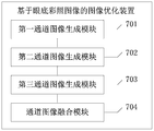
- FIG. 7 is a schematic structural diagram of an image optimization device based on fundus color photograph images according to an embodiment of the application.
- FIG. 1 The flow of an image optimization method based on a color fundus photo image of the first embodiment of the present application is shown in FIG. 1, and this embodiment includes the following steps:
- Step s101 Obtain a color fundus photo image to be optimized, perform RGB three-channel separation on the color fundus photo image to obtain a first RGB three-channel image, and obtain each channel according to each channel image in the first RGB three-channel image Grayscale histogram of the image;
- the fundus color photograph image refers to a fundus image newly taken by the patient, that is, a hospital clinical fundus color photograph examination result map.
- the fundus color photograph image can generally be obtained through the hospital, or can be automatically obtained by accessing the database of the hospital electronic system .
- the RGB three-channel separation of the color fundus photo image includes separating the color fundus photo image into three channels of red (R), green (G), and blue (B); because the color fundus photo image is being generated and stored At times, they are stored in RGB three channels, so through channel separation, the images of the R, G, and B channels can be extracted; in addition, usually 2D images are stored in three-dimensional information, including width, height and channel Therefore, through the channel separation, the width and height of each channel can be obtained; when the RGB three-channel separation is completed, the red (R), green (G) and blue (B) images of the three channels can be obtained, namely the first One RGB three-channel image.
- the gray level histogram is a function of the gray level distribution, and is a statistics of the gray level distribution in the image.
- the gray histogram is to count all the pixels in the digital image according to the size of the gray value, and count the frequency of their appearance.
- the gray-level histogram is a function of gray-level, it represents the number of pixels with a certain gray-level in the image, and reflects the frequency of a certain gray-level in the image.
- step s102 the non-extreme point region in the grayscale histogram of each channel image is subjected to brightness space transformation to obtain a second RGB three-channel image;
- the non-extreme point area refers to the one with the smallest pixel value removed.
- the part and the largest part of the point area can also be understood as the most of the pixels in the middle of the normal distribution.
- the extreme point area includes the maximum value and the minimum value.
- Step s103 adjusting the extreme point of each channel image in the second RGB three-channel image, adjusting the brightness of each channel image in the second RGB three-channel image, to obtain a third RGB three-channel image;
- the influence brought by the extreme points can be reduced by adjusting the extreme points of each channel image.
- the coordinate position and pixel value of the extreme point will not change, but in the second RGB three-channel image
- the pixel value of the non-extreme point area has changed, so the pixel value of the extreme point in the non-extreme point area of each channel image in the second RGB three-channel image can be replaced The extreme point of each channel image in the first RGB three-channel image before the brightness space transformation.
- the brightness of each channel image in the second RGB three-channel image may also be adjusted.
- the brightness can be adjusted by setting the target overall average brightness in advance, then calculating the current overall average brightness of each channel image, and adjusting the brightness according to the target overall average brightness of each channel image and the current overall average brightness to obtain a new R , G, B three-channel image, that is, the third RGB three-channel image.
- Step s104 fusing the three-channel images in the third RGB three-channel image to generate an optimized fundus color photo image.
- the channel image fusion is the reverse process of channel image separation.
- the channel image is separated, only the width and height of the channel are output, and when the channel image is fused, only the width and height of all channels are output at the same time.
- channel image fusion can be achieved; when the R, G, and B three-channel images in the third RGB three-channel image are fused, it can be generated Optimize the fundus color photo image.
- the fundus image can be enhanced and more in line with humans. Eye and vision habits to avoid image distortion.
- step s101 is obtained according to each channel image in the first RGB three-channel image Grayscale histogram of each channel image, including:
- Step s201 Calculate the gray value distribution of each channel image in the first RGB three-channel image
- the distribution of the image pixels of each channel image of R, G, and B in the gray value range of 0-255 can be calculated.
- step s202 a grayscale histogram of each channel image is generated according to the grayscale value distribution of each channel image.
- the gray level histogram of each channel image can be generated according to the distribution of the image pixels of each channel image of R, G, and B in the range of 0-255 gray value, where the abscissa is the pixel value of 0-255 , The ordinate is the number of pixels corresponding to the pixel value.
- the step s102, performing luminance space transformation on the non-extreme point area in the grayscale histogram of each channel image includes:
- x is the pixel value after transformation
- X O is the pixel value of the corresponding coordinate point before transformation
- P OL is the minimum gray value in the image before transformation
- P DL is the minimum value of the target image
- C before converting the contrast is O
- C D is the contrast of the image the target image.
- the image contrast can be changed through the brightness space conversion.
- the image contrast refers to the difference between the brightest and darkest parts of various colors in an image. The larger the difference, the higher the contrast. This has nothing to do with the resolution, only the darkest and the brightest. The higher the contrast, the more dazzling, brighter and more prominent an image is; the lower the contrast, the less obvious the change. The smaller is, the contrast in a given image is related to the change of color brightness in the image; while the contrast in the grayscale histogram refers to the distribution range of the grayscale histogram, that is, the "width", by changing the original image The grayscale distribution can change the contrast of the image.
- the pixels in the middle area of the grayscale histogram can be transformed into brightness space.
- the middle area refers to the area where the smallest part and the largest part of the pixel value are removed, which can also be understood as normal In the distribution, most of the pixels in the middle.
- x is the pixel value after transformation
- X O is the pixel value of the corresponding coordinate point before transformation
- P OL is the minimum gray value in the image before transformation
- P DL is the minimum value of the target image
- C O is before transformation
- C D is the contrast of the target image.
- the image contrast can be changed and the image can be optimized.
- Fig. 3 is a schematic flow chart of an image optimization method based on fundus color photograph images according to a third embodiment of the application. As shown in the figure, in step s103, the polarities of each channel image in the second RGB three-channel image are adjusted. Value points, including:
- Step s301 pre-store the extreme points of each channel image of the second RGB three-channel image that have not undergone brightness space conversion
- the position coordinates of these extreme points may be pre-stored before the luminance space transformation.
- the position coordinates of the extreme points include the position coordinates of the extreme points of each channel image, and the extreme points include the maximum value and the minimum value.
- Step s302 query the extreme points of the brightness space conversion area in each channel image of the second RGB three-channel image, and check the brightness space conversion area in each channel image of the second RGB three-channel image
- the extreme point value is assigned to the extreme point corresponding to the channel image of the second RGB three-channel image that has not undergone brightness space conversion.
- the non-extremum point area will generate a new non-extreme point area, and the new non-extreme point area will be generated.
- the extreme point areas that have not been transformed by the brightness space can be queried in each channel image of the second RGB three-channel image. When these extreme point areas are queried Then, the extreme point value of the brightness space conversion area in each channel image of the second RGB three-channel image can be assigned to the channel image of the second RGB three-channel image that has not been subjected to brightness space conversion. Extreme point.
- FIG. 4 is a schematic flowchart of an image optimization method based on fundus color photograph images according to a fourth embodiment of the application. As shown in the figure, the step s103 adjusts the brightness of each channel image in the second RGB three-channel image ,include:
- Step s401 preset the target overall average brightness of each channel image in the second RGB three-channel image
- the target overall average brightness of each channel image may be preset; the target overall average brightness is in line with human vision Habitual brightness; the preset target overall average brightness is also an empirical value, that is, obtained through experiments.
- Step s402 Calculate the current overall average brightness of each channel image in the second RGB three-channel image, and adjust the brightness of each channel image according to the target overall average brightness of each channel image and the current overall average brightness.
- the image brightness refers to an intuitive feeling of an image. If it is a grayscale image, it is related to the grayscale value. The higher the grayscale value, the brighter the image.
- After the image of each channel is transformed add up the values of all pixels in the transformed channel image and divide by the number of image pixels to obtain the overall average brightness, and the overall average brightness obtained after the calculation Adjust to be equal to the overall average brightness of the target.
- the fundus color photo image can be optimized.
- Fig. 5 is a schematic flow chart of an image optimization method based on fundus color photograph images according to the fifth embodiment of the application. As shown in the figure, in step s402, the current value of each channel image in the second RGB three-channel image is calculated.
- the overall average brightness including:
- Step s501 Obtain the number of pixels of each channel image according to the grayscale histogram of each channel image in the second RGB three-channel image, and count the total pixel value of each channel;
- the abscissa in the grayscale histogram is the pixel value, and the ordinate corresponds to the number of pixel values, it is easy to obtain the pixels of each channel image through the grayscale histogram of each channel image The number and total pixel value.
- step s502 the current overall average brightness of each channel image is calculated according to the total pixel value and the number of pixels of each channel.
- the median pixel value of each channel image is divided by the number of image pixels to obtain the current overall average brightness of each channel image.
- FIG. 6 is a schematic flow chart of an image optimization method based on fundus color photograph images according to the sixth embodiment of the application.
- the step s402 is based on the target overall average brightness and current overall average brightness of each channel image Brightness adjusts the brightness of each channel image, including:
- Step s601 obtaining the overall average brightness difference of each channel image according to the target overall average brightness of each channel image and the current overall average brightness;
- the overall target average brightness of each channel image is subtracted from the current overall average brightness to obtain the overall average brightness of each channel image
- the average brightness is poor.
- Step s602 obtaining the overall average brightness difference of each pixel in each channel image according to the number of pixels of each channel image and the overall average brightness difference;
- the overall average brightness difference of each channel image is divided by the number of pixels in each channel image to obtain each channel image.
- the overall average brightness difference of pixels is divided by the number of pixels in each channel image.
- step s603 the pixel value of each pixel is adjusted according to the overall average brightness difference of each pixel in the image of each channel.
- the overall average brightness difference of each pixel in each channel image is obtained, the overall average brightness difference of each pixel is added to the pixel value corresponding to each pixel in each channel image.
- the brightness of each channel image can be adjusted, and the entire image can be optimized.
- FIG. 7 The structure of an image optimization device based on fundus color photograph images according to an embodiment of the application is shown in FIG. 7, and includes:
- the first channel image generation module includes:
- a statistical unit configured to separately count the gray value distribution of each channel image in the first RGB three-channel image
- the generating unit is configured to generate a grayscale histogram of each channel image according to the grayscale value distribution of each channel image.
- the second channel image generation module is configured to set the non-extreme point area in the grayscale histogram of each channel image according to the formula: Perform brightness space transformation, where x is the pixel value after transformation, X O is the pixel value of the corresponding coordinate point before transformation, P OL is the minimum gray value in the image before transformation, P DL is the minimum value of the target image, C before converting the contrast is O, C D is the contrast of the image the target image.
- the third channel image generation module includes:
- a pre-storage unit configured to pre-store the extreme points of each channel image of the second RGB three-channel image that have not undergone brightness space conversion
- the query unit is configured to query the extreme points of the brightness space conversion area in each channel image of the second RGB three-channel image, and perform brightness space conversion on each channel image of the second RGB three-channel image
- the extreme point value of the area is assigned to the extreme point corresponding to the channel image of the second RGB three-channel image that has not undergone brightness space conversion.
- the third channel image generation module further includes:
- a preset unit configured to preset the target overall average brightness of each channel image in the second RGB three-channel image
- the adjustment unit is configured to calculate the current overall average brightness of each channel image in the second RGB three-channel image, and adjust the brightness of each channel image according to the target overall average brightness of each channel image and the current overall average brightness.
- the third channel image generation module further includes:
- a pixel acquisition unit configured to acquire the number of pixels of each channel image according to the grayscale histogram of each channel image in the second RGB three-channel image, and count the total pixel value of each channel;
- the calculation unit is configured to calculate the current overall average brightness of each channel image according to the total pixel value and the number of pixels of each channel.
- the third channel image generation module further includes:
- the first brightness difference obtaining unit is configured to obtain the overall average brightness difference of each channel image according to the target overall average brightness of each channel image and the current overall average brightness;
- the second brightness difference obtaining unit is configured to obtain the overall average brightness difference of each pixel in each channel image according to the number of pixels of each channel image and the overall average brightness difference;
- the pixel value adjustment unit is configured to adjust the pixel value of each pixel according to the overall average brightness difference of each pixel in each channel image.
- An embodiment of the present application also discloses a computer device that includes a memory and a processor.
- the memory stores computer-readable instructions.
- the computer-readable instructions are executed by one or more of the processors, , Enabling one or more of the processors to execute the steps in the image optimization method in the foregoing embodiments.
- the embodiment of the present application also discloses a storage medium that can be read and written by a processor, and the memory stores computer-readable instructions.
- the computer-readable instructions are executed by one or more processors, One or more processors execute the steps in the image optimization method described in the foregoing embodiments.
- the computer program can be stored in a computer readable storage medium. When executed, it may include the procedures of the above-mentioned method embodiments.
- the aforementioned storage medium may be a non-volatile storage medium such as a magnetic disk, an optical disc, a read-only memory (Read-Only Memory, ROM), or a random access memory (Random Access Memory, RAM), etc.
Landscapes
- Engineering & Computer Science (AREA)
- Physics & Mathematics (AREA)
- General Physics & Mathematics (AREA)
- Theoretical Computer Science (AREA)
- Computer Vision & Pattern Recognition (AREA)
- Image Processing (AREA)
- Eye Examination Apparatus (AREA)
Abstract
本申请涉及人工智能领域,本申请公开了一种基于眼底彩照图像的图像优化方法及相关设备,所述方法包括:获取待优化眼底彩照图像,对所述眼底彩照图像进行RGB三通道分离,对分离后的通道图像进行优化处理,并对优化处理的通道图像进行融合,生成优化眼底彩照图像。本申请通过对眼底图像进行三通道分离,并对分离后的通道分别进行优化,再对优化后的三通道图像进行融合,生成优化眼底图像,可使得眼底图像得到增强,更加符合人眼视觉习惯,避免图像失真。
Description
本申请要求于2019年01月18日提交中国专利局、申请号为201910046451.1、发明名称为“基于眼底彩照图像的图像优化方法及相关设备”的中国专利申请的优先权,其全部内容通过引用结合在本申请中。
本申请涉及人工智能领域,特别涉及一种基于眼底彩照图像的图像优化方法及相关设备。
眼底图像包含血管、视盘、黄斑区域等多种生理结构,随着年龄的增长,极易发生病变。由于不同病人眼底病变程度的不同,生病种类的不同,人种的不同,以及获取眼底图像相机的型号,品牌的不同,所生成的眼底图像风格很难统一,不利于人工智能算法进行学习。
目前市面上的眼底图像优化方法,例如CLAHE等算法,都是对眼底图像特定区域进行增强,以进行血管和病灶的分割。但是这些优化方法都会使眼底图像失真严重,色调不统一,不利于人工智能算法进行学习。尽管目前,可以通过Photo Shop等图像软件,根据AREDS等研究方法,对图像进行优化调整,但耗费人力和时间,效率低下。
发明内容
本申请的目的在于针对现有技术的不足,提供一种基于眼底彩照图像的图像优化方法及相关设备,通过对眼底图像进行三通道分离,并对分离后的通道分别进行优化,再对优化后的三通道图像进行融合,生成优化眼底图像,可使得眼底图像得到增强,更加符合人眼视觉习惯,避免图像失真。
为达到上述目的,本申请的技术方案提供一种基于眼底彩照图像的图像优化方法及相关设备。
本申请公开了一种基于眼底彩照图像的图像优化方法,包括以下步骤:
获取待优化眼底彩照图像,对所述眼底彩照图像进行RGB三通道分离,获 得第一RGB三通道图像,并根据所述第一RGB三通道图像中的每个通道图像获得每个通道图像的灰度直方图;
将每个通道图像的灰度直方图中的非极值点区域进行亮度空间变换,获得第二RGB三通道图像;
调整所述第二RGB三通道图像中每个通道图像的极值点,调整所述第二RGB三通道图像中每个通道图像的亮度,获得第三RGB三通道图像;
对所述第三RGB三通道图像中的三个通道图像进行融合,生成优化眼底彩照图像。
本申请还公开了一种基于眼底彩照图像的图像优化装置,所述装置包括:
第一通道图像生成模块:设置为获取待优化眼底彩照图像,对所述眼底彩照图像进行RGB三通道分离,获得第一RGB三通道图像,并根据所述第一RGB三通道图像中的每个通道图像获得每个通道图像的灰度直方图;
第二通道图像生成模块:设置为将每个通道图像的灰度直方图中的非极值点区域进行亮度空间变换,获得第二RGB三通道图像;
第三通道图像生成模块:设置为调整所述第二RGB三通道图像中每个通道图像的极值点,调整所述第二RGB三通道图像中每个通道图像的亮度,获得第三RGB三通道图像;
通道图像融合模块:设置为对所述第三RGB三通道图像中的三个通道图像进行融合,生成优化眼底彩照图像。
本申请还公开了一种计算机设备,所述计算机设备包括存储器和处理器,所述存储器中存储有计算机可读指令,所述计算机可读指令被一个或多个所述处理器执行时,使得一个或多个所述处理器执行以下步骤:
获取待优化眼底彩照图像,对所述眼底彩照图像进行RGB三通道分离,获得第一RGB三通道图像,并根据所述第一RGB三通道图像中的每个通道图像获得每个通道图像的灰度直方图;
将每个通道图像的灰度直方图中的非极值点区域进行亮度空间变换,获得第二RGB三通道图像;
调整所述第二RGB三通道图像中每个通道图像的极值点,调整所述第二RGB 三通道图像中每个通道图像的亮度,获得第三RGB三通道图像;
对所述第三RGB三通道图像中的三个通道图像进行融合,生成优化眼底彩照图像。
本申请还公开了一种存储介质,所述存储介质可被处理器读写,所述存储介质存储有计算机指令,所述计算机可读指令被一个或多个处理器执行时,使得一个或多个处理器执行以下步骤:
获取待优化眼底彩照图像,对所述眼底彩照图像进行RGB三通道分离,获得第一RGB三通道图像,并根据所述第一RGB三通道图像中的每个通道图像获得每个通道图像的灰度直方图;
将每个通道图像的灰度直方图中的非极值点区域进行亮度空间变换,获得第二RGB三通道图像;
调整所述第二RGB三通道图像中每个通道图像的极值点,调整所述第二RGB三通道图像中每个通道图像的亮度,获得第三RGB三通道图像;
对所述第三RGB三通道图像中的三个通道图像进行融合,生成优化眼底彩照图像。
本申请的有益效果是:本申请通过对眼底图像进行三通道分离,并对分离后的通道分别进行优化,再对优化后的三通道图像进行融合,生成优化眼底图像,可使得眼底图像得到增强,更加符合人眼视觉习惯,避免图像失真。
图1为本申请第一个实施例的一种基于眼底彩照图像的图像优化方法的流程示意图;
图2为本申请第二个实施例的一种基于眼底彩照图像的图像优化方法的流程示意图;
图3为本申请第三个实施例的一种基于眼底彩照图像的图像优化方法的流程示意图;
图4为本申请第四个实施例的一种基于眼底彩照图像的图像优化方法的流程示意图;
图5为本申请第五个实施例的一种基于眼底彩照图像的图像优化方法的流 程示意图;
图6为本申请第六个实施例的一种基于眼底彩照图像的图像优化方法的流程示意图;
图7为本申请实施例的一种基于眼底彩照图像的图像优化装置结构示意图。
为了使本申请的目的、技术方案及优点更加清楚明白,以下结合附图及实施例,对本申请进行进一步详细说明。应当理解,此处所描述的具体实施例仅仅用以解释本申请,并不用于限定本申请。
本技术领域技术人员可以理解,除非特意声明,这里使用的单数形式“一”、“一个”、“所述”和“该”也可包括复数形式。应该进一步理解的是,本申请的说明书中使用的措辞“包括”是指存在所述特征、整数、步骤、操作、元件和/或组件,但是并不排除存在或添加一个或多个其他特征、整数、步骤、操作、元件、组件和/或它们的组。
本申请第一个实施例的一种基于眼底彩照图像的图像优化方法流程如图1所示,本实施例包括以下步骤:
步骤s101,获取待优化眼底彩照图像,对所述眼底彩照图像进行RGB三通道分离,获得第一RGB三通道图像,并根据所述第一RGB三通道图像中的每个通道图像获得每个通道图像的灰度直方图;
具体的,所述眼底彩照图像指的是病人新拍摄的眼底图像,即医院临床眼底彩照检查结果图,所述眼底彩照图像一般可通过医院获得,,也可通过访问医院电子系统的数据库自动获取。
具体的,所述对所述眼底彩照图像进行RGB三通道分离包括将眼底彩照图像分离成红(R)、绿(G)及蓝(B)三个通道;由于眼底彩照图像在生成及存储的时候都是以RGB三通道存储的,因此通过通道分离,可以将R、G、B三个通道的图像都提取出来;此外,通常2D图像在存储时存储的是三维信息,包括宽度高度和通道数,因此通过通道分离,可获得每个通道的宽度和高度;当完成RGB三通道分离之后,就可获得红(R)、绿(G)及蓝(B)三个通道的图像,即第一RGB三通道图像。
具体的,所述灰度直方图是关于灰度级分布的函数,是对图像中灰度级分布的统计。灰度直方图是将数字图像中的所有像素,按照灰度值的大小,统计其出现的频率。灰度直方图是灰度级的函数,它表示图像中具有某种灰度级的像素的个数,反映了图像中某种灰度出现的频率。当获得第一RGB三通道图像后,可对第一RGB三通道图像中的R、G、B三个通道的灰度级分布分别进行统计,并生成每个通道的灰度直方图。
步骤s102,将每个通道图像的灰度直方图中的非极值点区域进行亮度空间变换,获得第二RGB三通道图像;
具体的,当对所述第一RGB三通道图像的每个通道图像进行亮度空间变换时,只对非极值点区域进行变换,所述非极值点区域指的是去掉像素值最小的那部分和最大的那部分点的区域,也可理解为正态分布中,位于中间的大部分像素点,所述极值点区域包括极大值和极小值,当对每个通道图像的灰度直方图中的非极值点区域进行亮度空间变换之后,会获得新的R、G、B三个通道图像,即第二RGB三通道图像。
步骤s103,调整所述第二RGB三通道图像中每个通道图像的极值点,调整所述第二RGB三通道图像中每个通道图像的亮度,获得第三RGB三通道图像;
具体的,可通过调整每个通道图像的极值点来减小所述极值点带来的影响,在对所述第一RGB三通道图像中每个通道图像进行亮度空间变换之前,可预先存储所述第一RGB三通道图像中每个通道图像的极值点,当进行亮度空间变换之后,所述极值点的坐标位置和像素值不会发生变化,但是在所述第二RGB三通道图像中每个通道图像中,非极值点区域的像素值已经发生变化,因此可将所述第二RGB三通道图像中每个通道图像中非极值点区域的极值点像素值替换亮度空间变换之前的所述第一RGB三通道图像中每个通道图像的极值点。
具体的,调整所述第二RGB三通道图像中每个通道图像的极值点之后,还可对所述第二RGB三通道图像中每个通道图像的亮度进行调整,所述每个通道图像的亮度的调整可通过预先设置目标整体平均亮度,然后计算当前每个通道图像的整体平均亮度,根据所述每个通道图像的目标整体平均亮度和当前整体平均亮度进行亮度调整,获得新的R、G、B三个通道图像,即第三RGB三通道 图像。
步骤s104,对所述第三RGB三通道图像中的三个通道图像进行融合,生成优化眼底彩照图像。
具体的,所述通道图像融合是通道图像分离的逆过程,在通道图像分离时,只需将通道的宽度和高度输出,而在通道图像融合时,只需将所有通道的宽度和高度同时输出,因此只要将R、G、B三通道的图像同时显示,即可实现通道图像融合;当对第三RGB三通道图像中的R、G、B三个通道的图像进行融合之后,就可生成优化眼底彩照图像。
本实施例中,通过对眼底图像进行三通道分离,并对分离后的通道分别进行优化,再对优化后的三通道图像进行融合,生成优化眼底图像,可使得眼底图像得到增强,更加符合人眼视觉习惯,避免图像失真。
图2为本申请第二个实施例的一种基于眼底彩照图像的图像优化方法流程示意图,如图所示,所述步骤s101,根据所述第一RGB三通道图像中的每个通道图像获得每个通道图像的灰度直方图,包括:
步骤s201,对所述第一RGB三通道图像中的每个通道图像分别统计灰度值分布;
具体的,当获取第一RGB三通道图像中的每个通道图像后,可计算R、G、B每一通道图像的图像像素在0-255灰度值区间的分布情况。
步骤s202,根据所述每个通道图像的灰度值分布分别生成所属每个通道图像的灰度直方图。
具体的,可根据R、G、B每一通道图像的图像像素在0-255灰度值区间的分布情况生成每个通道图像的灰度直方图,其中,横坐标是0-255的像素值,纵坐标是对应像素值的像素的个数。
本实施例中,通过生成灰度直方图,可以更加直观了解灰度值的分布情况,有利于对图像进行后续优化处理。
在一个实施例中,所述步骤s102,将每个通道图像的灰度直方图中的非极值点区域进行亮度空间变换,包括:
将每个通道图像的灰度直方图中的非极值点区域根据公式:

具体的,可通过所述亮度空间变换改变图像对比度,所述图像对比度指的是,在一幅图像中,各种不同颜色最亮处和最暗处之间的差别,差别越大对比度越高,这个跟分辨率没有多少关系,只跟最暗和最亮有关系,对比度越高,一个图像给人的感觉就越刺眼,更加鲜亮,突出;越低则给人感觉变化不明显,反差就越小,因此对比度在给定的图像中,与图像中颜色亮度的变化有关;而对比度在灰度直方图中,就是指灰度直方图的分布范围,即“宽度”,通过改变原有图像的灰度分布就能改变图像的对比度。
具体的,可将所述灰度直方图中中间区域的像素进行亮度空间变换,所述中间区域指的是去掉像素值最小的那部分和最大的那部分点的区域,也可理解为正态分布中,位于中间的大部分像素点。
具体的,在进行亮度空间变换过程中,需满足以下公式:

其中,x为变换之后的像素值,X
O为变换之前对应坐标点的像素值,P
OL为变换之前图像中灰度极小值,P
DL为目标图像的极小值,C
O为变换之前图像的对比度,C
D为目标图像的对比度。
本实施例中,通过对通道图像进行亮度空间变换,可改变图像对比度,对图像进行优化。
图3为本申请第三个实施例的一种基于眼底彩照图像的图像优化方法流程示意图,如图所示,所述步骤s103,调整所述第二RGB三通道图像中每个通道图像的极值点,包括:
步骤s301,预先存储所述第二RGB三通道图像的每个通道图像中未进行亮度空间变换的极值点;
具体的,当在步骤s102中对所述第一RGB三通道图像的每个通道图像进行 亮度空间变换时,只对非极值点区域进行变换,因此当进行亮度空间变换后,这些极值点区域没有经过任何处理,且这些极值点区域的坐标位置和数值在所述第二RGB三通道图像的每个通道图像中不会有任何改变,会对图像的优化形成很大的干扰,因此可以在亮度空间变换前预先存储这些极值点的位置坐标,所述极值点的位置坐标包括每个通道图像的极值点位置坐标,所述极值点包括极大值和极小值。
步骤s302,查询所述第二RGB三通道图像的每个通道图像中进行亮度空间变换区域的极值点,并将所述第二RGB三通道图像的每个通道图像中进行亮度空间变换区域的极值点数值分配给与所述第二RGB三通道图像的通道图像对应的未进行亮度空间变换的极值点。
具体的,当对每个通道图像的灰度直方图中的非极值点区域进行亮度空间变换之后,所述非极值点区域会生成新的非极值点区域,而所述新的非极值点区域中也会有极值点,这时可以在所述第二RGB三通道图像的每个通道图像中查询未经过亮度空间变换的极值点区域,当查询到这些极值点区域后,可将所述第二RGB三通道图像的每个通道图像中进行亮度空间变换区域的极值点数值分配给与所述第二RGB三通道图像的通道图像对应的未进行亮度空间变换的极值点。
本实施例中,通过调整每个通道图像的极值点,可以减小极值点对图像优化的影响,提高优化效率。
图4为本申请第四个实施例的一种基于眼底彩照图像的图像优化方法流程示意图,如图所示,所述步骤s103,调整所述第二RGB三通道图像中每个通道图像的亮度,包括:
步骤s401,预设所述第二RGB三通道图像中每个通道图像的目标整体平均亮度;
具体的,在调整所述第二RGB三通道图像中每个通道图像的整体平均亮度之前,可预先设定每个通道图像的目标整体平均亮度;所述的目标整体平均亮度是符合人眼视觉习惯的亮度;所述预设的目标整体平均亮度也为经验值,即通过实验所得。
步骤s402,计算所述第二RGB三通道图像中每个通道图像的当前整体平均亮度,根据所述每个通道图像的目标整体平均亮度及当前整体平均亮度调整每个通道图像的亮度。
具体的,所述图像亮度指的是一幅图像给人的一种直观感受,如果是灰度图像,则跟灰度值有关,灰度值越高则图像越亮。当每个通道的图像经过变换之后,将变换后的通道图像中所有像素的值相加然后除以图像像素的个数,即可得到整体平均亮度,并将所述计算后得到的整体平均亮度调整到与目标整体平均亮度相等。
本实施例中,通过调整每个通道图像的整体平均亮度,可对眼底彩照图像进行优化。
图5为本申请第五个实施例的一种基于眼底彩照图像的图像优化方法流程示意图,如图所示,所述步骤s402,计算所述第二RGB三通道图像中每个通道图像的当前整体平均亮度,包括:
步骤s501,根据所述第二RGB三通道图像中每个通道图像的灰度直方图获取每个通道图像的像素个数,并统计每个通道的总像素值;
具体的,由于灰度直方图中,横坐标是像素值,纵坐标对应的是所属像素值的个数,因此可通过每个通道图像的灰度直方图,很容易获得每个通道图像的像素个数和总的像素值。
步骤s502,根据所述每个通道的总像素值及像素个数计算获得每个通道图像的当前整体平均亮度。
具体的,当获取到每个通道的总像素值及像素个数之后,将每个通道图像的中像素值然后除以图像像素的个数,即可得到每个通道图像的当前整体平均亮度。
本实施例中,通过获取当前整体平均亮度,有利于对整体平均亮度进行调整,进一步对眼底彩照图像进行优化。
图6为本申请第六个实施例的一种基于眼底彩照图像的图像优化方法流程示意图,如图所示,所述步骤s402,根据所述每个通道图像的目标整体平均亮度及当前整体平均亮度调整每个通道图像的亮度,包括:
步骤s601,根据所述每个通道图像的目标整体平均亮度及当前整体平均亮度获取每个通道图像的整体平均亮度差;
具体的,当获取到每个通道图像的目标整体平均亮度及当前整体平均亮度之后,将每个通道图像的目标整体平均亮度与当前整体平均亮度进行相减,即可获得每个通道图像的整体平均亮度差。
步骤s602,根据所述每个通道图像的像素个数及整体平均亮度差获取每个通道图像中每个像素的整体平均亮度差;
具体的,当获取到每个通道图像的整体平均亮度差之后,将所述每个通道图像的整体平均亮度差除以每个通道图像的像素个数,即可获得每个通道图像中每个像素的整体平均亮度差。
步骤s603,根据所述每个通道图像中每个像素的整体平均亮度差调整每个像素的像素值。
具体的,当获取到每个通道图像中每个像素的整体平均亮度差之后,在每个通道图像中的每个像素对应的像素值上加上所述每个像素的整体平均亮度差。
本实施例中,通过调整每个像素的像素值,可调整每个通道图像的亮度,对整个图像进行优化。
本申请实施例的一种基于眼底彩照图像的图像优化装置结构如图7所示,包括:
第一通道图像生成模块701、第二通道图像生成模块702、第三通道图像生成模块703及通道图像融合模块704;其中,第一通道图像生成模块701与第二通道图像生成模块702相连,第二通道图像生成模块702与第三通道图像生成模块703相连,第三通道图像生成模块703与通道图像融合模块704相连;第一通道图像生成模块701设置为获取待优化眼底彩照图像,对所述眼底彩照图像进行RGB三通道分离,获得第一RGB三通道图像,并根据所述第一RGB三通道图像中的每个通道图像获得每个通道图像的灰度直方图;第二通道图像生成模块702设置为将每个通道图像的灰度直方图中的非极值点区域进行亮度空间变换,获得第二RGB三通道图像;第三通道图像生成模块703设置为调整所述 第二RGB三通道图像中每个通道图像的极值点,调整所述第二RGB三通道图像中每个通道图像的亮度,获得第三RGB三通道图像;通道图像融合模块704设置为对所述第三RGB三通道图像中的三个通道图像进行融合,生成优化眼底彩照图像。
在一个实施例中,第一通道图像生成模块,包括:
统计单元,设置为对所述第一RGB三通道图像中的每个通道图像分别统计灰度值分布;
生成单元,设置为根据所述每个通道图像的灰度值分布分别生成所属每个通道图像的灰度直方图。
在一个实施例中,第二通道图像生成模块设置为将每个通道图像的灰度直方图中的非极值点区域根据公式:
 进行亮度空间变换,其中x为变换之后的像素值,X
O为变换之前对应坐标点的像素值,P
OL为变换之前图像中灰度极小值,P
DL为目标图像的极小值,C
O为变换之前图像的对比度,C
D为目标图像的对比度。
进行亮度空间变换,其中x为变换之后的像素值,X
O为变换之前对应坐标点的像素值,P
OL为变换之前图像中灰度极小值,P
DL为目标图像的极小值,C
O为变换之前图像的对比度,C
D为目标图像的对比度。
在一个实施例中,第三通道图像生成模块,包括:
预存储单元,设置为预先存储所述第二RGB三通道图像的每个通道图像中未进行亮度空间变换的极值点;
查询单元,设置为查询所述第二RGB三通道图像的每个通道图像中进行亮度空间变换区域的极值点,并将所述第二RGB三通道图像的每个通道图像中进行亮度空间变换区域的极值点数值分配给与所述第二RGB三通道图像的通道图像对应的未进行亮度空间变换的极值点。
在一个实施例中,第三通道图像生成模块,还包括:
预设单元,设置为预设所述第二RGB三通道图像中每个通道图像的目标整体平均亮度;
调整单元,设置为计算所述第二RGB三通道图像中每个通道图像的当前整体平均亮度,根据所述每个通道图像的目标整体平均亮度及当前整体平均亮度 调整每个通道图像的亮度。
在一个实施例中,第三通道图像生成模块,还包括:
像素获取单元,设置为根据所述第二RGB三通道图像中每个通道图像的灰度直方图获取每个通道图像的像素个数,并统计每个通道的总像素值;
计算单元,设置为根据所述每个通道的总像素值及像素个数计算获得每个通道图像的当前整体平均亮度。
在一个实施例中,第三通道图像生成模块,还包括:
第一亮度差获取单元,设置为根据所述每个通道图像的目标整体平均亮度及当前整体平均亮度获取每个通道图像的整体平均亮度差;
第二亮度差获取单元,设置为根据所述每个通道图像的像素个数及整体平均亮度差获取每个通道图像中每个像素的整体平均亮度差;
像素值调整单元,设置为根据所述每个通道图像中每个像素的整体平均亮度差调整每个像素的像素值。
本申请实施例还公开了一种计算机设备,所述计算机设备包括存储器和处理器,所述存储器中存储有计算机可读指令,所述计算机可读指令被一个或多个所述处理器执行时,使得一个或多个所述处理器执行上述各实施例中所述图像优化方法中的步骤。
本申请实施例还公开了一种存储介质,所述存储介质可被处理器读写,所述存储器存储有计算机可读指令,所述计算机可读指令被一个或多个处理器执行时,使得一个或多个处理器执行上述各实施例中所述图像优化方法中的步骤。
本领域普通技术人员可以理解实现上述实施例方法中的全部或部分流程,是可以通过计算机程序来指令相关的硬件来完成,该计算机程序可存储于一计算机可读取存储介质中,该程序在执行时,可包括如上述各方法的实施例的流程。其中,前述的存储介质可为磁碟、光盘、只读存储记忆体(Read-Only Memory,ROM)等非易失性存储介质,或随机存储记忆体(Random Access Memory,RAM)等。
以上所述实施例的各技术特征可以进行任意的组合,为使描述简洁,未对上述实施例中的各个技术特征所有可能的组合都进行描述,然而,只要这些技 术特征的组合不存在矛盾,都应当认为是本说明书记载的范围。
以上所述实施例仅表达了本申请的几种实施方式,其描述较为具体和详细,但并不能因此而理解为对本申请专利范围的限制。应当指出的是,对于本领域的普通技术人员来说,在不脱离本申请构思的前提下,还可以做出若干变形和改进,这些都属于本申请的保护范围。因此,本申请专利的保护范围应以所附权利要求为准。
Claims (20)
- 一种基于眼底彩照图像的图像优化方法,包括以下步骤:获取待优化眼底彩照图像,对所述眼底彩照图像进行RGB三通道分离,获得第一RGB三通道图像,并根据所述第一RGB三通道图像中的每个通道图像获得每个通道图像的灰度直方图;将每个通道图像的灰度直方图中的非极值点区域进行亮度空间变换,获得第二RGB三通道图像;调整所述第二RGB三通道图像中每个通道图像的极值点,调整所述第二RGB三通道图像中每个通道图像的亮度,获得第三RGB三通道图像;对所述第三RGB三通道图像中的三个通道图像进行融合,生成优化眼底彩照图像。
- 如权利要求1所述的基于眼底彩照图像的图像优化方法,其中,所述根据所述第一RGB三通道图像中的每个通道图像获得每个通道图像的灰度直方图,包括:对所述第一RGB三通道图像中的每个通道图像分别统计灰度值分布;根据所述每个通道图像的灰度值分布分别生成所属每个通道图像的灰度直方图。
- 如权利要求1所述的基于眼底彩照图像的图像优化方法,其中,所述将每个通道图像的灰度直方图中的非极值点区域进行亮度空间变换,包括:将每个通道图像的灰度直方图中的非极值点区域根据公式:进行亮度空间变换,其中x为变换之后的像素值,X O为变换之前对应坐标点的像素值,P OL为变换之前图像中灰度极小值,P DL为目标图像的极小值,C O为变换之前图像的对比度,C D为目标图像的对比度。

- 如权利要求1所述的基于眼底彩照图像的图像优化方法,其中,所述调整所述第二RGB三通道图像中每个通道图像的极值点,包括:预先存储所述第二RGB三通道图像的每个通道图像中未进行亮度空间变换的极值点;查询所述第二RGB三通道图像的每个通道图像中进行亮度空间变换区域的极值点,并将所述第二RGB三通道图像的每个通道图像中进行亮度空间变换区域的极值点数值分配给与所述第二RGB三通道图像的通道图像对应的未进行亮度空间变换的极值点。
- 如权利要求1所述的基于眼底彩照图像的图像优化方法,其中,所述调整所述第二RGB三通道图像中每个通道图像的亮度,包括:预设所述第二RGB三通道图像中每个通道图像的目标整体平均亮度;计算所述第二RGB三通道图像中每个通道图像的当前整体平均亮度,根据所述每个通道图像的目标整体平均亮度及当前整体平均亮度调整每个通道图像的亮度。
- 如权利要求5所述的基于眼底彩照图像的图像优化方法,其中,所述计算所述第二RGB三通道图像中每个通道图像的当前整体平均亮度,包括:根据所述第二RGB三通道图像中每个通道图像的灰度直方图获取每个通道图像的像素个数,并统计每个通道的总像素值;根据所述每个通道的总像素值及像素个数计算获得每个通道图像的当前整体平均亮度。
- 如权利要求6所述的基于眼底彩照图像的图像优化方法,其中,所述根据所述每个通道图像的目标整体平均亮度及当前整体平均亮度调整每个通道图像的亮度,包括:根据所述每个通道图像的目标整体平均亮度及当前整体平均亮度获取每个通道图像的整体平均亮度差;根据所述每个通道图像的像素个数及整体平均亮度差获取每个通道图像中每个像素的整体平均亮度差;根据所述每个通道图像中每个像素的整体平均亮度差调整每个像素的像素值。
- 一种基于眼底彩照图像的图像优化装置,所述装置包括:第一通道图像生成模块:设置为获取待优化眼底彩照图像,对所述眼底彩照图像进行RGB三通道分离,获得第一RGB三通道图像,并根据所述第一RGB 三通道图像中的每个通道图像获得每个通道图像的灰度直方图;第二通道图像生成模块:设置为将每个通道图像的灰度直方图中的非极值点区域进行亮度空间变换,获得第二RGB三通道图像;第三通道图像生成模块:设置为调整所述第二RGB三通道图像中每个通道图像的极值点,调整所述第二RGB三通道图像中每个通道图像的亮度,获得第三RGB三通道图像;通道图像融合模块:设置为对所述第三RGB三通道图像中的三个通道图像进行融合,生成优化眼底彩照图像。
- 根据权利要求8所述的基于眼底彩照图像的图像优化装置,其中,所述第一通道图像生成模块,包括:统计单元,设置为对所述第一RGB三通道图像中的每个通道图像分别统计灰度值分布;生成单元,设置为根据所述每个通道图像的灰度值分布分别生成所属每个通道图像的灰度直方图。
- 根据权利要求8所述的基于眼底彩照图像的图像优化装置,其中,所述第二通道图像生成模块,设置为将每个通道图像的灰度直方图中的非极值点区域根据公式:进行亮度空间变换,其中x为变换之后的像素值,X O为变换之前对应坐标点的像素值,P OL为变换之前图像中灰度极小值,P DL为目标图像的极小值,C O为变换之前图像的对比度,C D为目标图像的对比度。

- 根据权利要求8所述的基于眼底彩照图像的图像优化装置,其中,所述第三通道图像生成模块,包括:预存储单元,设置为预先存储所述第二RGB三通道图像的每个通道图像中未进行亮度空间变换的极值点;查询单元,设置为查询所述第二RGB三通道图像的每个通道图像中进行亮度空间变换区域的极值点,并将所述第二RGB三通道图像的每个通道图像中进行亮度空间变换区域的极值点数值分配给与所述第二RGB三通道图像的通道图 像对应的未进行亮度空间变换的极值点。
- 根据权利要求8所述的基于眼底彩照图像的图像优化装置,其中,所述第三通道图像生成模块,包括:预设单元,设置为预设所述第二RGB三通道图像中每个通道图像的目标整体平均亮度;调整单元,设置为计算所述第二RGB三通道图像中每个通道图像的当前整体平均亮度,根据所述每个通道图像的目标整体平均亮度及当前整体平均亮度调整每个通道图像的亮度。
- 根据权利要求8所述的基于眼底彩照图像的图像优化装置,其中,所述第三通道图像生成模块,包括:像素获取单元,设置为根据所述第二RGB三通道图像中每个通道图像的灰度直方图获取每个通道图像的像素个数,并统计每个通道的总像素值;计算单元,设置为根据所述每个通道的总像素值及像素个数计算获得每个通道图像的当前整体平均亮度。
- 根据权利要求8所述的基于眼底彩照图像的图像优化装置,其中,所述第三通道图像生成模块,包括:第一亮度差获取单元,设置为根据所述每个通道图像的目标整体平均亮度及当前整体平均亮度获取每个通道图像的整体平均亮度差;第二亮度差获取单元,设置为根据所述每个通道图像的像素个数及整体平均亮度差获取每个通道图像中每个像素的整体平均亮度差;像素值调整单元,设置为根据所述每个通道图像中每个像素的整体平均亮度差调整每个像素的像素值。
- 一种计算机设备,所述计算机设备包括存储器和处理器,所述存储器中存储有计算机可读指令,所述计算机可读指令被一个或多个所述处理器执行时,使得一个或多个所述处理器执行以下步骤:获取待优化眼底彩照图像,对所述眼底彩照图像进行RGB三通道分离,获得第一RGB三通道图像,并根据所述第一RGB三通道图像中的每个通道图像获得每个通道图像的灰度直方图;将每个通道图像的灰度直方图中的非极值点区域进行亮度空间变换,获得第二RGB三通道图像;调整所述第二RGB三通道图像中每个通道图像的极值点,调整所述第二RGB三通道图像中每个通道图像的亮度,获得第三RGB三通道图像;对所述第三RGB三通道图像中的三个通道图像进行融合,生成优化眼底彩照图像。
- 根据权利要求15所述的计算机设备,其中,所述调整所述第二RGB三通道图像中每个通道图像的极值点时,使得所述处理器执行以下步骤:预先存储所述第二RGB三通道图像的每个通道图像中未进行亮度空间变换的极值点;查询所述第二RGB三通道图像的每个通道图像中进行亮度空间变换区域的极值点,并将所述第二RGB三通道图像的每个通道图像中进行亮度空间变换区域的极值点数值分配给与所述第二RGB三通道图像的通道图像对应的未进行亮度空间变换的极值点。
- 根据权利要求15所述的计算机设备,其中,所述调整所述第二RGB三通道图像中每个通道图像的亮度时,使得所述处理器执行以下步骤:预设所述第二RGB三通道图像中每个通道图像的目标整体平均亮度;计算所述第二RGB三通道图像中每个通道图像的当前整体平均亮度,根据所述每个通道图像的目标整体平均亮度及当前整体平均亮度调整每个通道图像的亮度。
- 一种存储介质,所述存储介质可被处理器读写,所述存储介质存储有计算机指令,所述计算机可读指令被一个或多个处理器执行时,使得一个或多个处理器执行以下步骤:获取待优化眼底彩照图像,对所述眼底彩照图像进行RGB三通道分离,获得第一RGB三通道图像,并根据所述第一RGB三通道图像中的每个通道图像获得每个通道图像的灰度直方图;将每个通道图像的灰度直方图中的非极值点区域进行亮度空间变换,获得第二RGB三通道图像;调整所述第二RGB三通道图像中每个通道图像的极值点,调整所述第二RGB三通道图像中每个通道图像的亮度,获得第三RGB三通道图像;对所述第三RGB三通道图像中的三个通道图像进行融合,生成优化眼底彩照图像。
- 根据权利要求18所述的存储介质,其中,所述调整所述第二RGB三通道图像中每个通道图像的极值点时,使得一个或多个所述处理器执行以下步骤:预先存储所述第二RGB三通道图像的每个通道图像中未进行亮度空间变换的极值点;查询所述第二RGB三通道图像的每个通道图像中进行亮度空间变换区域的极值点,并将所述第二RGB三通道图像的每个通道图像中进行亮度空间变换区域的极值点数值分配给与所述第二RGB三通道图像的通道图像对应的未进行亮度空间变换的极值点。
- 根据权利要求18所述的存储介质,其中,所述调整所述第二RGB三通道图像中每个通道图像的亮度时,使得一个或多个所述处理器执行以下步骤:预设所述第二RGB三通道图像中每个通道图像的目标整体平均亮度;计算所述第二RGB三通道图像中每个通道图像的当前整体平均亮度,根据所述每个通道图像的目标整体平均亮度及当前整体平均亮度调整每个通道图像的亮度。
Applications Claiming Priority (2)
| Application Number | Priority Date | Filing Date | Title |
|---|---|---|---|
| CN201910046451.1A CN109919882B (zh) | 2019-01-18 | 2019-01-18 | 基于眼底彩照图像的图像优化方法及相关设备 |
| CN201910046451.1 | 2019-01-18 |
Publications (1)
| Publication Number | Publication Date |
|---|---|
| WO2020147245A1 true WO2020147245A1 (zh) | 2020-07-23 |
Family
ID=66960357
Family Applications (1)
| Application Number | Title | Priority Date | Filing Date |
|---|---|---|---|
| PCT/CN2019/089751 Ceased WO2020147245A1 (zh) | 2019-01-18 | 2019-06-03 | 基于眼底彩照图像的图像优化方法及相关设备 |
Country Status (2)
| Country | Link |
|---|---|
| CN (1) | CN109919882B (zh) |
| WO (1) | WO2020147245A1 (zh) |
Cited By (4)
| Publication number | Priority date | Publication date | Assignee | Title |
|---|---|---|---|---|
| CN113989137A (zh) * | 2021-10-21 | 2022-01-28 | 武汉博视电子有限公司 | 一种脸部肌肤图像色素沉着提取并形成棕区光谱的方法 |
| CN114663277A (zh) * | 2020-12-23 | 2022-06-24 | 比亚迪股份有限公司 | 图像处理方法、存储介质及智能终端 |
| CN115526980A (zh) * | 2022-10-12 | 2022-12-27 | 网易(杭州)网络有限公司 | 光效实现方法、装置、存储介质及计算机设备 |
| CN117876242A (zh) * | 2024-03-11 | 2024-04-12 | 深圳大学 | 眼底图像增强方法、装置、设备及可读存储介质 |
Families Citing this family (2)
| Publication number | Priority date | Publication date | Assignee | Title |
|---|---|---|---|---|
| CN115222607B (zh) * | 2021-04-20 | 2025-10-31 | Oppo广东移动通信有限公司 | 眼部图像的处理方法、装置、电子设备和存储介质 |
| CN113344809B (zh) * | 2021-05-27 | 2022-09-09 | 同济大学 | 一种超声图像增强方法、系统和设备 |
Citations (3)
| Publication number | Priority date | Publication date | Assignee | Title |
|---|---|---|---|---|
| JP2014083147A (ja) * | 2012-10-22 | 2014-05-12 | Canon Inc | 眼科システム及びその制御方法、画像処理装置、並びに、プログラム |
| CN106558031A (zh) * | 2016-12-02 | 2017-04-05 | 北京理工大学 | 一种基于成像模型的彩色眼底图的图像增强方法 |
| CN109166095A (zh) * | 2018-07-11 | 2019-01-08 | 广东技术师范学院 | 一种基于生成对抗机制的眼底影像杯盘分割方法 |
Family Cites Families (5)
| Publication number | Priority date | Publication date | Assignee | Title |
|---|---|---|---|---|
| US7664302B2 (en) * | 2003-07-18 | 2010-02-16 | Hologic, Inc. | Simultaneous grayscale and geometric registration of images |
| US7386186B2 (en) * | 2004-08-27 | 2008-06-10 | Micron Technology, Inc. | Apparatus and method for processing images |
| CN101873429B (zh) * | 2010-04-16 | 2012-09-05 | 杭州海康威视软件有限公司 | 图像对比度的处理方法及装置 |
| CN103455994A (zh) * | 2012-05-28 | 2013-12-18 | 佳能株式会社 | 图像模糊度的确定方法和设备 |
| CN107292835B (zh) * | 2017-05-31 | 2020-03-13 | 瑞达昇医疗科技(大连)有限公司 | 一种眼底图像视网膜血管自动矢量化的方法及装置 |
-
2019
- 2019-01-18 CN CN201910046451.1A patent/CN109919882B/zh active Active
- 2019-06-03 WO PCT/CN2019/089751 patent/WO2020147245A1/zh not_active Ceased
Patent Citations (3)
| Publication number | Priority date | Publication date | Assignee | Title |
|---|---|---|---|---|
| JP2014083147A (ja) * | 2012-10-22 | 2014-05-12 | Canon Inc | 眼科システム及びその制御方法、画像処理装置、並びに、プログラム |
| CN106558031A (zh) * | 2016-12-02 | 2017-04-05 | 北京理工大学 | 一种基于成像模型的彩色眼底图的图像增强方法 |
| CN109166095A (zh) * | 2018-07-11 | 2019-01-08 | 广东技术师范学院 | 一种基于生成对抗机制的眼底影像杯盘分割方法 |
Cited By (5)
| Publication number | Priority date | Publication date | Assignee | Title |
|---|---|---|---|---|
| CN114663277A (zh) * | 2020-12-23 | 2022-06-24 | 比亚迪股份有限公司 | 图像处理方法、存储介质及智能终端 |
| CN113989137A (zh) * | 2021-10-21 | 2022-01-28 | 武汉博视电子有限公司 | 一种脸部肌肤图像色素沉着提取并形成棕区光谱的方法 |
| CN115526980A (zh) * | 2022-10-12 | 2022-12-27 | 网易(杭州)网络有限公司 | 光效实现方法、装置、存储介质及计算机设备 |
| CN117876242A (zh) * | 2024-03-11 | 2024-04-12 | 深圳大学 | 眼底图像增强方法、装置、设备及可读存储介质 |
| CN117876242B (zh) * | 2024-03-11 | 2024-05-28 | 深圳大学 | 眼底图像增强方法、装置、设备及可读存储介质 |
Also Published As
| Publication number | Publication date |
|---|---|
| CN109919882A (zh) | 2019-06-21 |
| CN109919882B (zh) | 2023-07-21 |
Similar Documents
| Publication | Publication Date | Title |
|---|---|---|
| WO2020147245A1 (zh) | 基于眼底彩照图像的图像优化方法及相关设备 | |
| CN103024300B (zh) | 一种高动态范围图像显示方法及装置 | |
| CN104754239B (zh) | 拍照方法及装置 | |
| JP3959909B2 (ja) | ホワイトバランス調整方法及び調整装置 | |
| CN106060493A (zh) | 多源投影无缝边缘拼接方法及系统 | |
| CN111583127B (zh) | 人脸肤色校正方法、装置、计算机设备和可读存储介质 | |
| CN113298744B (zh) | 一种端到端的红外与可见光图像融合方法 | |
| WO2020140728A1 (en) | Image processing method, image processing apparatus and display apparatus | |
| WO2019061766A1 (zh) | 一种图像处理方法及装置 | |
| WO2017049703A1 (zh) | 图像对比度增强方法 | |
| WO2020135234A1 (zh) | 一种图像处理方法及装置 | |
| CN111292251B (zh) | 图像偏色校正方法、装置以及计算机存储介质 | |
| US12309536B2 (en) | Image processing method and apparatus, computer device, and storage medium | |
| CN114066780B (zh) | 4k内窥镜图像去雾方法、装置、电子设备及存储介质 | |
| CN103957396A (zh) | 利用智能设备进行舌诊时的图像处理方法、装置及设备 | |
| WO2020029877A1 (zh) | 多相机拼接的亮度调整方法及便携式终端 | |
| WO2019184667A1 (zh) | 一种全景图像的颜色校正方法和电子设备 | |
| WO2019200640A1 (zh) | 色域映射的方法和装置 | |
| WO2025189937A9 (zh) | 图像处理方法及电子设备 | |
| WO2022179087A1 (zh) | 视频处理方法及装置 | |
| CN116271386A (zh) | 一种具有成像增强功能的可视双腔气管插管及其成像增强方法 | |
| CN121056712A (zh) | 一种内窥镜多区域语义感知时域融合自适应白平衡算法 | |
| CN106686320A (zh) | 一种基于数密度均衡的色调映射方法 | |
| CN107358592B (zh) | 一种迭代式全局自适应图像增强方法 | |
| WO2020118977A1 (zh) | 图像色温校正方法及装置 |
Legal Events
| Date | Code | Title | Description |
|---|---|---|---|
| 121 | Ep: the epo has been informed by wipo that ep was designated in this application |
Ref document number: 19910564 Country of ref document: EP Kind code of ref document: A1 |
|
| NENP | Non-entry into the national phase |
Ref country code: DE |
|
| 122 | Ep: pct application non-entry in european phase |
Ref document number: 19910564 Country of ref document: EP Kind code of ref document: A1 |