WO2020145687A1 - 카메라 모듈 - Google Patents
카메라 모듈 Download PDFInfo
- Publication number
- WO2020145687A1 WO2020145687A1 PCT/KR2020/000396 KR2020000396W WO2020145687A1 WO 2020145687 A1 WO2020145687 A1 WO 2020145687A1 KR 2020000396 W KR2020000396 W KR 2020000396W WO 2020145687 A1 WO2020145687 A1 WO 2020145687A1
- Authority
- WO
- WIPO (PCT)
- Prior art keywords
- disposed
- liquid lens
- heating
- unit
- lens
- Prior art date
Links
Images


Classifications
-
- G—PHYSICS
- G03—PHOTOGRAPHY; CINEMATOGRAPHY; ANALOGOUS TECHNIQUES USING WAVES OTHER THAN OPTICAL WAVES; ELECTROGRAPHY; HOLOGRAPHY
- G03B—APPARATUS OR ARRANGEMENTS FOR TAKING PHOTOGRAPHS OR FOR PROJECTING OR VIEWING THEM; APPARATUS OR ARRANGEMENTS EMPLOYING ANALOGOUS TECHNIQUES USING WAVES OTHER THAN OPTICAL WAVES; ACCESSORIES THEREFOR
- G03B3/00—Focusing arrangements of general interest for cameras, projectors or printers
- G03B3/10—Power-operated focusing
-
- G—PHYSICS
- G02—OPTICS
- G02B—OPTICAL ELEMENTS, SYSTEMS OR APPARATUS
- G02B13/00—Optical objectives specially designed for the purposes specified below
- G02B13/001—Miniaturised objectives for electronic devices, e.g. portable telephones, webcams, PDAs, small digital cameras
- G02B13/0055—Miniaturised objectives for electronic devices, e.g. portable telephones, webcams, PDAs, small digital cameras employing a special optical element
- G02B13/0075—Miniaturised objectives for electronic devices, e.g. portable telephones, webcams, PDAs, small digital cameras employing a special optical element having an element with variable optical properties
-
- G—PHYSICS
- G02—OPTICS
- G02B—OPTICAL ELEMENTS, SYSTEMS OR APPARATUS
- G02B27/00—Optical systems or apparatus not provided for by any of the groups G02B1/00 - G02B26/00, G02B30/00
- G02B27/64—Imaging systems using optical elements for stabilisation of the lateral and angular position of the image
- G02B27/646—Imaging systems using optical elements for stabilisation of the lateral and angular position of the image compensating for small deviations, e.g. due to vibration or shake
-
- G—PHYSICS
- G02—OPTICS
- G02B—OPTICAL ELEMENTS, SYSTEMS OR APPARATUS
- G02B3/00—Simple or compound lenses
- G02B3/12—Fluid-filled or evacuated lenses
-
- G—PHYSICS
- G02—OPTICS
- G02B—OPTICAL ELEMENTS, SYSTEMS OR APPARATUS
- G02B7/00—Mountings, adjusting means, or light-tight connections, for optical elements
- G02B7/02—Mountings, adjusting means, or light-tight connections, for optical elements for lenses
- G02B7/028—Mountings, adjusting means, or light-tight connections, for optical elements for lenses with means for compensating for changes in temperature or for controlling the temperature; thermal stabilisation
-
- G—PHYSICS
- G02—OPTICS
- G02B—OPTICAL ELEMENTS, SYSTEMS OR APPARATUS
- G02B7/00—Mountings, adjusting means, or light-tight connections, for optical elements
- G02B7/02—Mountings, adjusting means, or light-tight connections, for optical elements for lenses
- G02B7/04—Mountings, adjusting means, or light-tight connections, for optical elements for lenses with mechanism for focusing or varying magnification
- G02B7/08—Mountings, adjusting means, or light-tight connections, for optical elements for lenses with mechanism for focusing or varying magnification adapted to co-operate with a remote control mechanism
-
- G—PHYSICS
- G03—PHOTOGRAPHY; CINEMATOGRAPHY; ANALOGOUS TECHNIQUES USING WAVES OTHER THAN OPTICAL WAVES; ELECTROGRAPHY; HOLOGRAPHY
- G03B—APPARATUS OR ARRANGEMENTS FOR TAKING PHOTOGRAPHS OR FOR PROJECTING OR VIEWING THEM; APPARATUS OR ARRANGEMENTS EMPLOYING ANALOGOUS TECHNIQUES USING WAVES OTHER THAN OPTICAL WAVES; ACCESSORIES THEREFOR
- G03B17/00—Details of cameras or camera bodies; Accessories therefor
- G03B17/55—Details of cameras or camera bodies; Accessories therefor with provision for heating or cooling, e.g. in aircraft
-
- G—PHYSICS
- G03—PHOTOGRAPHY; CINEMATOGRAPHY; ANALOGOUS TECHNIQUES USING WAVES OTHER THAN OPTICAL WAVES; ELECTROGRAPHY; HOLOGRAPHY
- G03B—APPARATUS OR ARRANGEMENTS FOR TAKING PHOTOGRAPHS OR FOR PROJECTING OR VIEWING THEM; APPARATUS OR ARRANGEMENTS EMPLOYING ANALOGOUS TECHNIQUES USING WAVES OTHER THAN OPTICAL WAVES; ACCESSORIES THEREFOR
- G03B30/00—Camera modules comprising integrated lens units and imaging units, specially adapted for being embedded in other devices, e.g. mobile phones or vehicles
-
- G—PHYSICS
- G03—PHOTOGRAPHY; CINEMATOGRAPHY; ANALOGOUS TECHNIQUES USING WAVES OTHER THAN OPTICAL WAVES; ELECTROGRAPHY; HOLOGRAPHY
- G03B—APPARATUS OR ARRANGEMENTS FOR TAKING PHOTOGRAPHS OR FOR PROJECTING OR VIEWING THEM; APPARATUS OR ARRANGEMENTS EMPLOYING ANALOGOUS TECHNIQUES USING WAVES OTHER THAN OPTICAL WAVES; ACCESSORIES THEREFOR
- G03B5/00—Adjustment of optical system relative to image or object surface other than for focusing
-
- H—ELECTRICITY
- H05—ELECTRIC TECHNIQUES NOT OTHERWISE PROVIDED FOR
- H05B—ELECTRIC HEATING; ELECTRIC LIGHT SOURCES NOT OTHERWISE PROVIDED FOR; CIRCUIT ARRANGEMENTS FOR ELECTRIC LIGHT SOURCES, IN GENERAL
- H05B1/00—Details of electric heating devices
- H05B1/02—Automatic switching arrangements specially adapted to apparatus ; Control of heating devices
- H05B1/0227—Applications
- H05B1/0252—Domestic applications
-
- H—ELECTRICITY
- H05—ELECTRIC TECHNIQUES NOT OTHERWISE PROVIDED FOR
- H05B—ELECTRIC HEATING; ELECTRIC LIGHT SOURCES NOT OTHERWISE PROVIDED FOR; CIRCUIT ARRANGEMENTS FOR ELECTRIC LIGHT SOURCES, IN GENERAL
- H05B3/00—Ohmic-resistance heating
- H05B3/84—Heating arrangements specially adapted for transparent or reflecting areas, e.g. for demisting or de-icing windows, mirrors or vehicle windshields
-
- G—PHYSICS
- G03—PHOTOGRAPHY; CINEMATOGRAPHY; ANALOGOUS TECHNIQUES USING WAVES OTHER THAN OPTICAL WAVES; ELECTROGRAPHY; HOLOGRAPHY
- G03B—APPARATUS OR ARRANGEMENTS FOR TAKING PHOTOGRAPHS OR FOR PROJECTING OR VIEWING THEM; APPARATUS OR ARRANGEMENTS EMPLOYING ANALOGOUS TECHNIQUES USING WAVES OTHER THAN OPTICAL WAVES; ACCESSORIES THEREFOR
- G03B2205/00—Adjustment of optical system relative to image or object surface other than for focusing
- G03B2205/0007—Movement of one or more optical elements for control of motion blur
-
- G—PHYSICS
- G03—PHOTOGRAPHY; CINEMATOGRAPHY; ANALOGOUS TECHNIQUES USING WAVES OTHER THAN OPTICAL WAVES; ELECTROGRAPHY; HOLOGRAPHY
- G03B—APPARATUS OR ARRANGEMENTS FOR TAKING PHOTOGRAPHS OR FOR PROJECTING OR VIEWING THEM; APPARATUS OR ARRANGEMENTS EMPLOYING ANALOGOUS TECHNIQUES USING WAVES OTHER THAN OPTICAL WAVES; ACCESSORIES THEREFOR
- G03B2205/00—Adjustment of optical system relative to image or object surface other than for focusing
- G03B2205/0053—Driving means for the movement of one or more optical element
- G03B2205/0084—Driving means for the movement of one or more optical element using other types of actuators
-
- G—PHYSICS
- G03—PHOTOGRAPHY; CINEMATOGRAPHY; ANALOGOUS TECHNIQUES USING WAVES OTHER THAN OPTICAL WAVES; ELECTROGRAPHY; HOLOGRAPHY
- G03B—APPARATUS OR ARRANGEMENTS FOR TAKING PHOTOGRAPHS OR FOR PROJECTING OR VIEWING THEM; APPARATUS OR ARRANGEMENTS EMPLOYING ANALOGOUS TECHNIQUES USING WAVES OTHER THAN OPTICAL WAVES; ACCESSORIES THEREFOR
- G03B2217/00—Details of cameras or camera bodies; Accessories therefor
- G03B2217/007—Details of energy supply or management
-
- H—ELECTRICITY
- H05—ELECTRIC TECHNIQUES NOT OTHERWISE PROVIDED FOR
- H05B—ELECTRIC HEATING; ELECTRIC LIGHT SOURCES NOT OTHERWISE PROVIDED FOR; CIRCUIT ARRANGEMENTS FOR ELECTRIC LIGHT SOURCES, IN GENERAL
- H05B2203/00—Aspects relating to Ohmic resistive heating covered by group H05B3/00
- H05B2203/002—Heaters using a particular layout for the resistive material or resistive elements
-
- H—ELECTRICITY
- H05—ELECTRIC TECHNIQUES NOT OTHERWISE PROVIDED FOR
- H05B—ELECTRIC HEATING; ELECTRIC LIGHT SOURCES NOT OTHERWISE PROVIDED FOR; CIRCUIT ARRANGEMENTS FOR ELECTRIC LIGHT SOURCES, IN GENERAL
- H05B2203/00—Aspects relating to Ohmic resistive heating covered by group H05B3/00
- H05B2203/016—Heaters using particular connecting means
-
- H—ELECTRICITY
- H05—ELECTRIC TECHNIQUES NOT OTHERWISE PROVIDED FOR
- H05B—ELECTRIC HEATING; ELECTRIC LIGHT SOURCES NOT OTHERWISE PROVIDED FOR; CIRCUIT ARRANGEMENTS FOR ELECTRIC LIGHT SOURCES, IN GENERAL
- H05B2213/00—Aspects relating both to resistive heating and to induction heating, covered by H05B3/00 and H05B6/00
- H05B2213/07—Heating plates with temperature control means
Definitions
- the embodiment relates to a camera module.
- the various shooting functions include at least one of an optical zoom function (zoom-in/zoom-out), an auto-focusing (AF) function, or an image stabilization or image stabilization (OIS) function.
- an optical zoom function zoom-in/zoom-out
- AF auto-focusing
- OIS image stabilization or image stabilization
- the autofocus and image stabilization functions are fixed to the lens holder and are performed by tilting or tilting a plurality of lenses aligned with the optical axis in the vertical direction of the optical axis or optical axis.
- a separate lens driving device for driving is required.
- the lens driving device has high power consumption, and there is a problem in that the overall size of the existing camera module is increased, such as adding a cover glass separately from the camera module to protect it.
- studies have been conducted on a liquid lens unit that performs autofocus and image stabilization functions by electrically adjusting the curvatures of the interfaces of two liquids.
- the liquid lens unit may not be able to accurately perform the above-described function by causing a phase change at a low temperature. Particularly, when the liquid contained in the liquid lens unit changes phase from a low temperature to a solid, the liquid lens unit has a slow reaction speed, and thus cannot perform the OIS function properly, thereby deteriorating its performance.
- the embodiment is to provide a camera module capable of maintaining the same temperature despite changes in the temperature of the surrounding environment.
- the technical problem to be solved in the embodiment is not limited to the technical problem mentioned above, and another technical problem not mentioned will be clearly understood by a person having ordinary knowledge in the technical field to which the present invention belongs from the following description. Will be able to.
- a camera module includes a liquid lens; A first connecting substrate disposed above or below the liquid lens; A second connecting substrate disposed on the other of the liquid lens above or below; A temperature sensor for sensing the temperature of the liquid lens; And a control unit outputting a heating voltage corresponding to the sensed temperature, wherein at least one of the first or second connection substrates includes a heating unit that generates heat in response to the heating voltage, and the heating unit is the liquid. It may be disposed at a position corresponding to the upper or lower surface of the lens.
- the liquid lens may include a first plate including a cavity in which an inclined surface is formed to place a conductive liquid and a non-conductive liquid; A first electrode disposed on one surface of the first plate and electrically connected to the first connection substrate; A second electrode disposed on the other surface of the first plate and electrically connected to the second connection substrate; A second plate disposed above or below the first plate; And a third plate disposed on the other of the first or above the first plate, wherein the first plate is formed at a position corresponding to the third plate and a first opening formed at a position corresponding to the second plate. And a second opening having a different size from the first opening.
- the heating unit may be disposed around the opening having a small size among the first opening and the second opening.
- the heating unit is disposed on the second connection substrate, and is disposed around the second opening having a larger size among the first and second openings, and is applied to the second heating voltage included in the heating voltage.
- the second heating unit that is heated may be further included.
- the first connecting substrate may include a first hollow having a diameter equal to or greater than the diameter of the first opening; A first support portion disposed around the first hollow; And a first heating wire disposed as the first heating portion in the first support portion.
- the first heating wire may be embedded in the first support.
- the first connection substrate further includes a first connection pad electrically connected to the control unit, and the first connection pad comprises: a first electrode terminal connecting the first electrode to the control unit; And a first heating terminal connecting the first heating wire to the control unit.
- the second connecting substrate may include a second hollow having a diameter equal to or greater than the diameter of the second opening; A second support portion disposed around the second hollow; And a second heating wire disposed as the second heating portion in the second support portion.
- the second heating wire may be embedded in the second support.
- the second connection substrate may further include a second connection pad electrically connected to the control unit, and the second connection pad may include a second electrode terminal connecting the second electrode to the control unit; And a second heating terminal connecting the second heating wire to the control unit.
- the second connection pad may further include a temperature terminal connecting the temperature sensor to the control unit.
- At least one of the first or second heating wires may have a heating pattern.
- the camera module may be disposed to surround the liquid lens, and may further include a spacer including a receiving groove accommodating the temperature sensing unit.
- the receiving groove may be formed inside the spacer facing the liquid lens.
- the camera module according to the embodiment can help the liquid lens maintain the same temperature even at low temperatures by transferring heat to the liquid lens by using a heating unit when the temperature of the liquid lens is low, so that its function, in particular, the OIS function is applied to the temperature. It can be performed accurately regardless of
- the camera module according to the embodiment may stably fix or couple the liquid lens unit to the holder using an adhesive member.
- the manufacturing process and manufacturing cost may not be increased.
- FIG. 1 is a schematic side view of a camera module according to an embodiment.
- FIG. 2 is an exploded perspective view according to an embodiment of the camera module shown in FIG. 1.
- FIG. 3 is a cross-sectional view of the camera module shown in FIG. 2 taken along line A-A'.
- FIGS. 2 and 3 are views for explaining the holder, the liquid lens unit, and the first and second adhesive members shown in FIGS. 2 and 3.
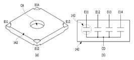
- 5A and 5B show a top perspective view and a bottom view, respectively, of a first connecting substrate.
- 6A, 6B, and 6C show a front top perspective view, a rear top perspective view, and a top view, respectively, of the second connecting substrate.
- FIG. 7 is a sectional view showing an embodiment of the liquid lens unit described above.
- FIG. 8 is a schematic block diagram of a camera module.
- 9A and 9B are views for explaining a liquid lens whose interface is adjusted in response to a driving voltage.
- the top (top) or bottom (bottom) (on or under) when described as being formed on the “top (top)” or “bottom (bottom) (on or under)” of each element, the top (top) or bottom (bottom) (on or under) ) Includes both two elements directly contacting each other or one or more other elements formed indirectly between the two elements.
- the top (top) or bottom (bottom) (on or under) when expressed as “up (up)” or “down (down)” (on or under), it may include the meaning of the downward direction as well as the upward direction based on one element.
- the variable lens may be a variable focus lens. Also, the variable lens may be a lens whose focus is adjusted.
- the variable lens may be at least one of a liquid lens, a polymer lens, a liquid crystal lens, a VCM type, and an SMA type.
- the liquid lens may include a liquid lens including one liquid and a liquid lens including two liquids.
- the liquid lens including one liquid may change the focus by adjusting the membrane disposed at a position corresponding to the liquid, and for example, the focus may be changed by pressing the membrane by the electromagnetic force of the magnet and the coil.
- the liquid lens including two liquids may control the interface formed by the conductive liquid and the non-conductive liquid by using a voltage applied to the liquid lens, including the conductive liquid and the non-conductive liquid.
- the polymer lens can change the focus of the polymer material through a driving unit such as a piezo.
- the liquid crystal lens can change the focus by controlling the liquid crystal by electromagnetic force.
- the VCM type can change the focus by adjusting the solid lens or the lens assembly including the solid lens through an electromagnetic force between the magnet and the coil.
- the SMA type may use a shape memory alloy to control a solid lens or a lens assembly including the solid lens to change focus.
- variable lens included in the camera modules 100 and 200 according to the embodiment will be described as a liquid lens, but the embodiment is not limited thereto.
- the camera module 100 will be described using a Cartesian coordinate system, but the embodiment is not limited thereto. That is, according to the Cartesian coordinate system, the x-axis, y-axis, and z-axis are orthogonal to each other, but the embodiment is not limited thereto. That is, the x-axis, y-axis, and z-axis may intersect each other instead of being orthogonal.
- FIG. 1 shows a schematic side view of a camera module 100 according to an embodiment.
- the camera module 100 may include a lens assembly 22, a control circuit 24 and an image sensor 26.
- the lens assembly 22 may include a plurality of lens units and a holder accommodating the plurality of lens units.
- the plurality of lens units may include a liquid lens unit, and may further include a first lens unit or a second lens unit.
- the plurality of lens units may include both the first and second lens units and the liquid lens unit.
- the control circuit 24 serves to supply a driving voltage (or an operating voltage) to the liquid lens unit.
- control circuit 24 and the image sensor 26 may be disposed on one printed circuit board (PCB), but this is only one example and the embodiment is not limited thereto.
- PCB printed circuit board
- the configuration of the control circuit 24 may be designed differently according to specifications required by the optical device.
- the control circuit 24 may be implemented as a single chip, thereby reducing the intensity of the driving voltage applied to the lens assembly 22. Through this, the size of the optical device mounted on the portable device can be further reduced.
- FIG. 2 is an exploded perspective view according to an embodiment of the camera module 100 shown in FIG. 1.
- the camera module 100 may include a lens assembly, a main substrate 150, an image sensor 182 and a heating unit H (not shown in FIG. 2 ).
- the camera module 100 may further include a temperature sensor 190.
- the camera module 100 may further include a middle base 172.
- the camera module 100 may further include a filter 176 and a sensor base 178.
- the camera module 100 may further include at least one adhesive member. At least one adhesive member serves to bond or fix the liquid lens unit 140 to the holder 120. 2, at least one adhesive member is illustrated as including both the first adhesive member 162 and the second adhesive member 164, but the embodiment is not limited thereto.
- the at least one adhesive member may include only some of the first adhesive member 162 and the second adhesive member 164.
- Each of the first and second adhesive members 162 and 164 may include an adhesive, an epoxy, and the like, and the adhesive may include a silicone-based material, a sealing material, or a photo-curable adhesive material.
- the embodiments are not limited to the specific materials of the first and second adhesive members 162 and 164.
- the first adhesive member 162 and the second adhesive member 164 may include the same material as each other, or may include different materials.
- At least one of the components 110 to 190 of the camera module 100 illustrated in FIG. 2 may be omitted. Alternatively, at least one component different from the components 110 to 190 illustrated in FIG. 2 may be further included in the camera module 100.
- FIG. 3 is a cross-sectional view of the camera module 100 shown in FIG. 2 taken along line A-A'.
- the lens assembly includes a first lens unit 110, a holder 120, a second lens unit 130, a liquid lens unit 140, a first adhesive member 162, or a second At least one of the adhesive member 164 may be included, and may correspond to the lens assembly 22 shown in FIG. 1.
- the lens assembly may be disposed on the main substrate 150.
- the first lens unit 110 and the second lens unit 130 may be referred to as'first solid lens unit' and'second solid lens unit', respectively.
- the first lens unit 110 is disposed on the upper side of the lens assembly, and may be a region where light is incident from the outside of the lens assembly. That is, the first lens unit 110 may be disposed on the liquid lens unit 140 in the holder 120.
- the first lens unit 110 may be embodied as one lens, or may be embodied as two or more lenses that are aligned with respect to the central axis to form an optical system.
- the central axis means the optical axis (LX) of the optical system formed by the first lens unit 110, the liquid lens unit 140, and the second lens unit 130 included in the camera module 100. It may mean, or may mean an axis parallel to the optical axis LX.
- the optical axis LX may correspond to the optical axis of the image sensor 182. That is, the first lens unit 110, the liquid lens unit 140, the second lens unit 130, and the image sensor 182 are arranged in an optical axis LX through active alignment (AA). Can be.
- the active alignment means that the optical axes of the first lens unit 110, the second lens unit 130, and the liquid lens unit 140 are matched for better image acquisition, and the image sensor 182 and the lens units are aligned. It may mean an operation of adjusting an axial or distance relationship between (110, 130, 140).
- the active alignment is generated by the image sensor 182 receiving light incident from a specific object through at least one of the first lens unit 110, the second lens unit 130, or the liquid lens unit 140. It may be performed through an operation of analyzing one image data. For example, active alignment may be performed in the following order.
- Active alignment to adjust the relative position between the liquid lens unit 140 inserted in the holder 120 and the image sensor 182 may be performed.
- the first alignment may be performed while the gripper is variable to various positions while holding the middle base 172, and the second alignment may be performed while the gripper holds the spacer 143 of the liquid lens unit 140. It can be performed with variable position.
- the active alignment may be performed in a different order from the above-described order.
- the camera module 100 may include a middle base 172 having a thicker thickness than the protrusion 124 of the holder 120.
- the thickness of the holder 120 may be necessary to form the shape of the holder 120 that is relatively more complicated than the shape of the middle base 172 using injection or the like. If the thickness of the corresponding portion of the holder 120 for active alignment is not sufficient for grip, the middle base 172 may be added to grip the middle base 172 portion to perform active alignment. However, if the thickness of the protrusion 124 is sufficiently thick, the middle base 172 may be omitted. Further, the protrusion 124 and the middle base 172 may be coupled to each other by an adhesive member, for example, epoxy.
- active alignment for adjusting a relative position between the first lens unit 110 and the second lens unit 130 and the liquid lens unit 140 fixed to the holder 120 is completed.
- an active alignment (fourth alignment) may be performed to adjust the relative position between the lens of the third alignment completed lens assembly and the image sensor 182.
- the third alignment may be performed while varying the spacer 143 of the liquid lens unit 140 to various positions while holding the spacer 143, and the fourth alignment may be performed at various positions while the gripper grips the middle base 172. It can be performed while varying.
- the first lens unit 110 may include, for example, two lenses 110-1 and 110-3, but this is exemplary and the first lens unit 110 The number of lenses included in) may be 1 or 3 or more.
- the first lens spacer 110-2 has two lenses 110-1 and 110- to maintain a constant distance between the two lenses 110-1 and 110-3 to compensate for errors in lens manufacturing. 3) can be placed between. In some cases, the lens spacer 110-2 may be omitted.
- an exposure lens may be disposed on an image side of the first lens unit 110.
- the exposure lens may mean the outermost lens among the lenses included in the first lens unit 110. That is, since the lens 110-1 positioned on the uppermost side of the first lens unit 110 protrudes upward, it can perform the function of an exposure lens.
- the exposed lens protrudes out of the holder 120 and has a possibility of damaging the surface. If the surface of the exposure lens is damaged, the image quality of the image taken by the camera module 100 may deteriorate.
- a cover glass is disposed on the top of the exposed lens, a coating layer is formed, or the rigidity of the lens of other lens parts is prevented to prevent surface damage of the exposed lens
- the exposure lens can also be implemented with a strong wear-resistant material.
- each of the lenses 110-1 and 110-3 included in the first lens unit 110 may increase toward the lower portion (eg, -z-axis direction), but embodiments are not limited thereto. Does not.
- FIGS. 4A to 4C are views illustrating the holder 120, the liquid lens unit 140, the first adhesive member 162, and the second adhesive member 164 illustrated in FIGS. 2 and 3. That is, FIG. 4A shows an exploded perspective view of the holder 120, the liquid lens unit 140, the first adhesive member 162, and the second adhesive member 164, and FIG. 4B shows the holder 120, the liquid lens unit ( 140), an exploded plan view of the first adhesive member 162 and the second adhesive member 164, and FIG. 4C shows the holder 120, the liquid lens unit 140, the first adhesive member 162, and the second adhesive It shows the bonding plan view of the member 164. In FIG. 4C, the first and second adhesive members 162 and 164 are hidden by the holder 120 and are not visible.
- the holder 120 may include first and second holes H1 and H2 and first to fourth sidewalls (or side or side parts) S1, S2, S3, and S4.
- the first and second holes H1 and H2 are formed on the upper and lower portions of the holder 120, respectively, to open the upper and lower portions of the holder 120, respectively.
- the first hole H1 and the second hole H2 may be through holes.
- the first lens unit 110 may be accommodated, mounted, seated, contacted, fixed, temporarily fixed, supported, combined, or disposed in the first hole H1 formed inside the holder 120
- the 130 may be accommodated, mounted, seated, contacted, fixed, temporarily fixed, supported, coupled, or disposed in the second hole H2 formed inside the holder 120.
- first and second sidewalls S1 and S2 of the holder 120 are disposed to face each other in a direction perpendicular to the optical axis LX direction (for example, the x-axis direction), and the third and fourth sidewalls (S3, S4) may be disposed facing each other in a direction perpendicular to the optical axis (LX) direction (for example, the y-axis direction).
- the first sidewall S1 in the holder 120 includes a first opening OP1
- the second sidewall S2 has the same or similar shape as the first opening OP1.
- the second opening OP2 may be included. Accordingly, the first opening OP1 disposed on the first sidewall S1 and the second opening OP2 disposed on the second sidewall S2 are perpendicular to the optical axis LX direction (for example, the x-axis). Direction).
- the inner space of the holder 120 in which the liquid lens unit 140 is to be disposed may be opened by the first and second openings OP1 and OP2.
- the liquid lens unit 140 is inserted through the first or second openings OP1 and OP2 to be mounted, seated, contacted, fixed, temporarily fixed, supported, combined, or disposed in the inner space of the holder 120 Can.
- the liquid lens unit 140 may be inserted into the interior space of the holder 120 through the first opening OP1.
- the liquid lens unit 140 may be inserted into the space inside the holder 120 through the first or second openings OP1 and OP2, so that the first of the holder 120 is based on the optical axis LX direction.
- the size of each of the second openings OP1 and OP2 may be larger than a cross-sectional area of the liquid lens unit 140 in the y-axis and z-axis directions.
- the height H corresponding to the size of each of the first and second openings OP1 and OP2 in the direction of the optical axis LX may be greater than the thickness T of the liquid lens unit 140.
- the second lens unit 130 may be disposed under the liquid lens unit 140 inside the holder 120.
- the second lens unit 130 may be arranged to be spaced apart from the first lens unit 110 in the optical axis direction (eg, the z-axis direction).
- the second lens unit 130 may be implemented as a single lens, or may be implemented as two or more lenses that are aligned with respect to a central axis to form an optical system.
- the second lens unit 130 may include three lenses 130-1, 130-3 and 130-5, but this is exemplary and 2
- the number of lenses included in the lens unit 130 may be 2 or less or 4 or more.
- the second and third lens spacers 130-2 and 130-4 that compensate for errors in lens manufacturing by maintaining a constant distance between the three lenses 130-1, 130-3, and 130-5 It can be disposed between adjacent lenses.
- the second lens spacer 130-2 is disposed between the two lenses 130-1 and 130-3, and the third lens spacer 130-4 is the two lenses 130-3 and 130-5. ). In some cases, at least one of the second or third lens spacers 130-2 and 130-4 may be omitted.
- each of the lenses 130-1, 130-3, and 130-5 included in the second lens unit 130 may increase toward the lower portion (eg, -z axis direction), but the embodiment Is not limited to this.
- each of the first lens unit 110 and the second lens unit 130 is a solid lens, and may be implemented as glass or plastic, but an embodiment includes the first lens unit 110 and The second lens unit 130 is not limited to each specific material.
- the liquid lens unit 140 may include first portions 140-1 to fifth portions 140-5.
- the first portion 140-1 is the first hole H1 of the holder 120 in an optical axis (LX) direction or a direction parallel to the optical axis (LX) direction (eg, z-axis direction).
- the second hole H2 may be a part that is mounted, seated, contacted, fixed, temporarily fixed, supported, coupled, or disposed in the inner space. That is, the first portion 140-1 of the liquid lens unit 140 may be disposed between the first lens unit 110 and the second lens unit 130.
- the embodiment is not limited to this.
- the first lens unit 110 or the second lens unit 130 may be omitted, and the liquid lens unit 140 may be a holder 120 rather than the first lens unit 110.
- the liquid lens unit 140 may be disposed on the lower side in the holder 120 than the second lens unit 130.
- the first portion 140-1 of the liquid lens unit 140 is provided with a first opening OP1 of the holder 120 in a direction perpendicular to the optical axis LX direction (eg, the x-axis direction). It may be a part that is mounted, seated, contacted, fixed, temporarily fixed, supported, coupled, or disposed in the interior space between the two openings OP2.
- the second and third portions 140-2 and 140-3 of the liquid lens unit 140 may be portions disposed in the first and second openings OP1 and OP2 of the holder 120, respectively.
- the second and third portions 140-2 and 140-3 are described in detail when the first and second adhesive members 162 and 164 are described.
- the fourth portion 140-4 of the liquid lens unit 140 may be a portion protruding from the first sidewall S1 of the holder 120.
- the fourth portion 140-4 of the liquid lens unit 140 protrudes from the first opening OP1 formed in the first sidewall S1 of the holder 120.
- the fourth portion 140-4 may be a portion protruding out of the holder 120 from the first opening OP1 side.
- the fifth portion 140-5 of the liquid lens unit 140 may be a portion protruding from the second side wall S2 of the holder 120.
- the fifth portion 140-5 of the liquid lens unit 140 protrudes from the second opening OP2 formed in the second sidewall S2 of the holder 120.
- the fifth part 140-5 may be a part protruding out of the holder 120 from the second opening OP2 side.
- the liquid lens unit 140 may include first to fifth regions A1, A2, A3, A4, and A5.
- the first area A1 is an area between the second area A2 and the third area A3, which corresponds to the first portion 140-1 shown in FIG. 4C, and the second area A2 is a holder ( The area disposed inside the first opening OP1 of 120 corresponds to the second part 140-2 shown in FIG. 4C, and the third area A3 is the second opening OP2 of the holder 120 ), which corresponds to the third portion 140-3 shown in FIG. 4C.
- the fourth area A4 is an area protruding from the first opening OP1 of the holder 120 and corresponds to the fourth part 140-4 shown in FIG. 4C. That is, the fourth area A4 is an area disposed outside the holder 120 on the first opening OP1 side.
- the fifth region A5 is a region protruding from the second opening OP2 of the holder 120 and may correspond to the fifth portion 140-5 illustrated in FIG. 4C. That is, the fifth area A5 is an area disposed outside the holder 120 on the second opening OP2 side.
- the liquid lens unit 140 includes a first connecting substrate 141, a liquid lens (or liquid lens body) 142, a spacer 143, and a second connecting substrate 144. It can contain.
- the first connection substrate 141 may be disposed above or below the liquid lens 142.
- the first connection substrate 141 may be a separate electrode connection substrate disposed on the liquid lens 142, as shown in FIGS. 2 and 3.
- the first connection substrate 141 and the second connection substrate 144 serve to supply voltage to the liquid lens 142.
- the first connection substrate 141 may electrically connect a plurality of first electrodes (not shown) included in the liquid lens 142 to the main substrate 150.
- the first connection board 141 may be implemented as a flexible printed circuit board (FPCB).
- 5A and 5B show a top perspective view and a bottom view of the first connecting substrate 141, respectively.
- the first connection substrate 141 is electrically connected to each of the plurality of first electrodes through first to fourth wirings W1 to W4, and first to electrically connected to the first to fourth wirings W1 to W4.
- the first substrate pad 150-1 formed on the main substrate 150 may be electrically connected through the connection pad ET. To this end, after the liquid lens unit 140 is inserted into the inner space of the holder 120, the first connecting substrate 141 is bent toward the main substrate 150 in the -z axis direction, and then 1
- the connection pad ET and the first substrate pad 150-1 may be electrically connected by conductive epoxy or soldering.
- the first connecting substrate 141 is connected to a conductive first holder surface electrode disposed, formed, or coated on the surface of the holder 120 to form a conductive first holder surface electrode disposed on the surface of the holder 120. It may be electrically connected to the main substrate 150 through, but the embodiment is not limited thereto.
- the second connection substrate 144 may be disposed on the liquid lens 142 above or below the other.
- the second connection substrate 144 may be a common electrode connection substrate disposed under the liquid lens 142, as shown in FIGS. 2 and 3.
- the first connection substrate 141 and the second connection substrate 144 serve to supply voltage to the liquid lens 142.
- the second connection substrate 144 may electrically connect a second electrode (not shown) included in the liquid lens 142 to the main substrate 150.
- the first and second electrodes will be described in detail with reference to FIG. 7 described below.
- the second connection substrate 144 may be implemented as an FPCB or a single metal substrate (conductive metal plate).
- 6A, 6B, and 6C show a front top perspective view, a rear top perspective view, and a top view, respectively, of the second connection substrate 144.
- the second connection substrate 144 is electrically connected to the second electrode through the fifth and sixth wirings W5, W5-1, W6, and W6-1, and the fifth and sixth wirings W5 and W5-1 , W6, W6-1) may be electrically connected to the second substrate pad 150-2 formed on the main substrate 150 through a second connection pad CT commonly connected to the W6-1 (eg, CT1). .
- CT commonly connected to the W6-1
- the second connection substrate 144 is disposed on, formed, or coated on the surface of the holder 120 and is connected to the conductive second holder surface electrode to form a conductive second holder surface electrode on the surface of the holder 120. It may be electrically connected to the main substrate 150 through, but the embodiment is not limited thereto.
- the liquid lens 142 may include a cavity (CA). As illustrated in FIG. 3, the opening area in the direction in which light is incident from the cavity CA may be smaller than the opening area in the opposite direction. Alternatively, the liquid lens 142 may be disposed such that the inclined direction of the cavity CA is opposite. That is, as illustrated in FIG. 3, the opening area in the direction in which light is incident from the cavity CA may be larger than the opening area in the opposite direction. In addition, when the liquid lens 142 is disposed such that the inclined direction of the cavity CA is opposite, all or part of the arrangement of the components included in the liquid lens 142 is changed together according to the inclined direction of the liquid lens 142 Alternatively, only the inclined direction of the cavity CA may be changed, and the arrangement of the remaining components may not be changed. Other detailed configuration of the liquid lens 142 will be described later in detail with reference to FIG. 7.
- the spacer 143 is disposed to surround the side surface of the liquid lens 142 in a ring shape, thereby protecting the liquid lens 142 from external impact.
- the spacer 143 may have a shape in which the liquid lens 142 can be mounted, seated, contacted, fixed, temporarily fixed, supported, coupled, or disposed therein.
- the spacer 143 may include a hollow 143H1 receiving the liquid lens 142 and a frame surrounding the hollow 143H1 formed in the middle.
- the spacer 143 may have a square planar shape (hereinafter, referred to as a ‘ ⁇ ’ shape) with a center hole, but the embodiment is not limited thereto.
- the spacer 143 may be disposed between the first connecting substrate 141 and the second connecting substrate 144.
- the upper and lower portions of the spacer 143 may include concave-convex portions to increase the bonding force with the first and second connecting substrates 141 and 144 through an adhesive material.
- the spacer 143 may be disposed to protrude from at least one of the first or second openings OP1 and OP2 of the holder 120.
- the spacer 143 is the first or second of the holder 120 in a direction perpendicular to the optical axis LX (eg, in the x-axis direction) together with the first and second connecting substrates 141 and 144 It may have a shape protruding from at least one of the second side walls S1 and S2. This is because the length of the spacer 143 in the x-axis direction is longer than the length of the holder 120 in the x-axis direction. Accordingly, the portions protruding from the first and second sidewalls S1 and S2 in the spacer 143 are the fourth and fifth portions 140-4 and 140-5 of the liquid lens unit 140 shown in FIG. 4C. 3, that is, each of the fourth region A4 and the fifth region A5 illustrated in FIG. 3.
- the spacer 143 when the spacer 143 is inserted into the holder 120 and in an active alignment process, the spacer 143 may contact the gripper.
- the spacer 143 may not be disposed in the first opening OP1 and the second opening OP2. Alternatively, at least a portion of the spacer 143 may be disposed inside at least one of the first opening OP1 or the second opening OP2. As illustrated in FIGS. 2, 4A, and 4B, since the spacer 143 has a'W' shape and surrounds the liquid lens 142, at least a portion of the spacer 143 has first and second openings ( It can be seen that it may be disposed inside each of OP1 and OP2).
- the liquid lens 142 may be disposed inside at least one of the first opening OP1 or the second opening OP2. Referring to FIG. 3, it can be seen that the first plate 147 of the liquid lens 142, which is a component of the liquid lens 142, is disposed in each of the first and second openings OP1 and OP2.
- the first adhesive member 162 may be disposed between the holder 120 and the liquid lens unit 140 in the first opening OP1 of the holder 120. As illustrated in FIG. 3, the first adhesive member 162 is disposed in the second area A2 of the liquid lens unit 140, and the upper surface of the second portion 140-2 of the liquid lens unit 140. , It can be arranged on the lower surface and the side.
- the second adhesive member 164 may be disposed between the holder 120 and the liquid lens unit 140 in the second opening OP2 of the holder 120. As illustrated in FIG. 3, the second adhesive member 164 is disposed in the third area A3 of the liquid lens unit 140, and an upper surface of the third portion 140-3 of the liquid lens unit 140. , It can be arranged on the lower surface and the side.
- the holder 120 may include a holder upper region 120U disposed on the liquid lens unit 140 and a holder lower region 120D disposed under the liquid lens unit 140.
- each of the first and second adhesive members 162 and 164 may combine the upper portion of the holder 120U and the lower portion of the holder 120D with the liquid lens unit 140.
- the liquid lens unit 140 may be stably fixed to and coupled to the holder 120.
- each of the first and second adhesive members 162 and 164 illustrated in FIG. 2 is illustrated as being a hexahedron, but the embodiment is not limited thereto. That is, if the first and second adhesive members 162 and 164 can be disposed between the liquid lens unit 140 and the holder 120 in the first and second openings OP1 and OP2, respectively, the first and second 2 It is not limited to the specific shape of the adhesive members 162 and 164. That is, the first and second adhesive members 162 and 164 may have shapes corresponding to the shapes of the first and second openings OP1 and OP2. In addition, each of the first and second adhesive members 162 and 164 may be integral as shown in FIG. 2, or may be divided into a plurality of segments as shown in FIG. 2.
- the middle base 172 may be disposed while surrounding the second hole H2 of the holder 120.
- the middle base 172 may include an accommodation hole 172H for accommodating the second hole H2.
- the inner diameter of the middle base 172 ie, the diameter of the receiving hole 172H
- the shapes of the receiving holes 172H and the second holes H2 of the middle base 172 are shown to be circular, but the embodiment is not limited thereto and may be changed to various shapes.
- the filter 176 is disposed between the middle base 172 and the image sensor 182, and a specific wavelength for light passing through the first lens unit 110, the liquid lens 142, and the second lens unit 130
- the light corresponding to the range can be filtered.
- the filter 176 may be an infrared (IR) blocking filter or an ultraviolet (UV) blocking filter, but embodiments are not limited thereto.
- the filter 176 can block ultraviolet light that may be transmitted from the lens assembly, particularly light in the UV-A region.
- UV-C has a relatively short wavelength, so its penetration is small, so most of it is blocked from the ozone layer, and UV-B is blocked by ordinary glass, but UV-A passes through ordinary glass, and a separate blocking layer may be particularly necessary.
- the filter 176 may block light in the infrared (IR) region.
- filter 176 is shown as a single layer, it is only intended to indicate the presence of filter 176. That is, the filter 176 may be a single layer as illustrated in FIG. 2, or may be multi-layered as illustrated in FIG. 2.
- the filter 176 may be disposed inside the sensor base 178.
- the filter 176 may be disposed or mounted in the inner groove or step of the sensor base 178.
- the sensor base 178 may be disposed under the middle base 172 and attached to the main substrate 150.
- the sensor base 178 may surround the image sensor 182 and protect the image sensor 182 from external foreign matter or impact. In some cases, at least one of the filter 176 or the sensor base 178 may be omitted.
- the camera module 100 may further include first and second covers (not shown).
- the first cover is disposed to surround the holder 120, the liquid lens unit 140, and the middle base 172, thereby protecting a plurality of lenses (eg, 120, 140) forming an optical system from external impact can do.
- the first cover may include an upper opening formed on its upper surface so that the first lens unit 110 disposed on the holder 120 is exposed to external light.
- a window made of a light-transmitting material may be disposed in the upper opening, whereby foreign matter such as dust or moisture can be prevented from entering the camera module 100.
- the receiving hole 172H may be formed at a position corresponding to the position of the image sensor 182 disposed in the camera module 100 near the center of the middle base 172.
- the second cover is mounted on the main substrate 150 to protect the circuit element 151 disposed on the main substrate 150 from external impact.
- the second cover may include a space for accommodating the circuit element 151 in consideration of the shape and position of the circuit element 151 disposed on the main substrate 150.
- the plurality of circuit elements 151 may cause electromagnetic interference (EMI) or noise.
- the power inductor among the plurality of circuit elements 151 may cause more EMI than other elements.
- the second cover may be disposed to cover the circuit element 151 disposed in the element area of the main substrate 150.
- the circuit element 151 disposed on the main substrate 150 may be protected from external impact.
- the main substrate 150 includes a groove 150H, a circuit element 151, and a connection part (or FPCB) in which the image sensor 182 can be mounted, seated, contacted, fixed, temporarily fixed, supported, coupled, or accommodated. 152) and a connector 153.
- a connection part or FPCB
- the main substrate 150 may include a holder region in which the holder 120 is disposed and an element region in which a plurality of circuit elements 151 are disposed.
- the sensor base 178 may be mounted in the holder area spaced apart from the device area of the main substrate 150.
- the holder base 120 on which the middle base 172, the second lens unit 130, the liquid lens unit 140, and the first lens unit 110 are disposed may be disposed on the sensor base 178.
- the circuit element 151 of the main substrate 150 may constitute a control module that controls the liquid lens unit 140 and the image sensor 182.
- the circuit element 151 may include at least one of a passive element and an active element, and may have various widths and heights.
- a plurality of circuit elements 151 may be provided and may protrude to the outside while having a height higher than that of the main substrate 150.
- the element region in which the circuit element 151 is disposed on the main substrate 150 and the holder region in which the holder 120 is disposed may be disposed so as not to overlap in a direction parallel to the optical axis LX.
- the plurality of circuit elements 151 may include a power inductor and a gyro sensor, but the embodiment is not limited to a specific type of the circuit element 151.
- the connector 153 may electrically connect the main board 150 to a power source external to the camera module 100 or other devices (for example, an application processor).
- the main substrate 150 may be implemented as a Rigid Flexible Printed Circuit Board (RFPCB) including the FPCB 152.
- the FPCB 152 may be bent as required by the space where the camera module 100 is mounted.
- the image sensor 182 images light passing through the first lens unit 110, the liquid lens unit 140, and the second lens unit 130 of the lens assemblies 110, 120, 130, 140, 162, and 164. It can perform the function of converting to data. More specifically, the image sensor 182 may convert light into an analog signal through a pixel array including a plurality of pixels, and synthesize digital signals corresponding to the analog signals to generate image data.
- liquid lens unit 140 included in the camera module 100 will be described with reference to FIG. 7 as follows.
- FIG. 7 shows a cross-sectional view according to the embodiment 140A of the liquid lens unit 140 described above.
- the liquid lens unit 140A illustrated in FIG. 7 may include a first connection substrate 141, a liquid lens 142, a spacer 143, and a second connection substrate 144.
- a first connection substrate 141 For convenience of description, the illustration of the spacer 143 in FIG. 7 is omitted, and the description of the spacer 143 is the same as described above, so a duplicate description is omitted.
- the liquid lens 142 includes a plurality of different types of liquids LQ1 and LQ2, the first to third plates 147, 145, and 146, the first and second electrodes E1 and E2, and the insulating layer 148. It may include.
- the plurality of liquids LQ1 and LQ2 may include a first liquid LQ1 having conductivity and a second liquid (or insulating liquid) LQ2 having nonconductivity.
- the first liquid LQ1 and the second liquid LQ2 do not mix with each other, and an interface BO may be formed at a contact portion between the first and second liquids LQ1 and LQ2.
- the second liquid LQ2 may be disposed on the first liquid LQ1, but embodiments are not limited thereto.
- the edges of the first and second liquids LQ2 and LQ1 may be thinner than the center portion.
- the inner surface of the first plate 147 may form a side wall i of the cavity CA.
- the first plate 147 may include upper and lower third and fourth openings having predetermined slopes. That is, the cavity CA may be defined as an area surrounded by an inclined surface of the first plate 147, a third opening on the second plate 145 side, and a fourth opening on the third plate 146 side.
- the diameter of the wider fourth opening among the third and fourth openings may vary depending on the field of view (FOV) required by the liquid lens 142 or the role that the liquid lens 142 should play in the camera module 100.
- the size (or area, or width or diameter) O2 of the fourth opening may be larger than the size (or area, or width or diameter) O1 of the third opening.
- the size of each of the third and fourth openings may be a cross-sectional area in the horizontal direction (eg, x-axis and y-axis).
- the size of each of the third and fourth openings may mean a diameter if the opening is circular, and a length of a diagonal line if the opening is square.
- the interface BO formed by the two liquids LQ1 and LQ2 may move along the inclined surface of the cavity CA by the driving voltage.
- the cavity CA in which the first liquid LQ1 and the second liquid LQ2 are formed, and the inclined surface is formed, is a portion through which the light passing through the first lens unit 110 is transmitted. Therefore, the first plate 147 may be made of a transparent material, or may contain impurities so that light is not easily transmitted.
- Electrodes may be disposed on one surface and the other surface of the first plate 147, respectively.
- the plurality of first electrodes E1 may be disposed to be spaced apart from the second electrode E2, and may be disposed on one surface (eg, an upper surface, side surfaces, and lower surfaces) of the first plate 147.
- the second electrode E2 is disposed on at least a portion of the other surface (eg, a lower surface) of the first plate 147 and may directly contact the first liquid LQ1.
- first electrode E1 may be n electrodes (hereinafter referred to as “individual electrodes”), and the second electrode E2 may be one electrode (hereinafter referred to as “common electrodes”).
- n may be a positive integer of 2 or more.
- Each of the first and second electrodes E1 and E2 may include at least one electrode sector.
- the first electrode E1 may include a plurality of first electrode sectors electrically spaced from each other, and the second electrode E2 may include at least one second electrode sector.
- the electrode sector may mean a part of the electrode.
- the plurality of first electrode sectors may be sequentially arranged along the optical axis in a clockwise direction (or counterclockwise direction).
- the first electrode E1 may be electrically connected to the control unit through the first connection substrate 141 and the first substrate pad 150-1. To this end, the first electrode E1 is electrically connected to the first connection substrate 141, and the first connection substrate 141 is provided with a first substrate pad 150 through a plurality of wires and a first connection pad ET. -1) and the first substrate pad 150-1 may be electrically connected to the control unit. To this end, the first connection substrate 141 may include a plurality of wires and a first connection pad ET.
- the control unit may be included in the control circuit 24 described above.
- the first connection pad ET includes four first electrode terminals ET1 to ET4, and the other side of the first to fourth wirings W1 to W4 is provided with the first electrode terminals ET1 to ET4. Each can be electrically connected.
- one side of the first wire W1 is connected to one of the four first electrode sectors, and the other side of the first wire W1 is electrically connected to one of the first electrode terminals ET1 to ET4 (ET1).
- one side of each of the second to fourth wirings W2 to W4 is electrically connected to a corresponding electrode sector among the first electrode sectors, and the other side corresponds to a corresponding electrode terminal of the first electrode terminals ET2 to ET4. It can be electrically connected.
- the first electrode terminals ET1 to ET4 of the first connection pad ET may be electrically connected to the control unit through the first substrate pad 150-1 of the main substrate 150.
- the second electrode E2 may be electrically connected to the control unit through the second connection substrate 144 and the second substrate pad 150-2.
- the second electrode E2 is electrically connected to the second connection substrate 144, and the second connection substrate 144 is provided with a second substrate pad 150 through a plurality of wires and a second connection pad CT. -2), and the second substrate pad 150-2 may be electrically connected to the control unit.
- the second connection substrate 144 may include a plurality of wires and a second connection pad CT.
- the fifth and sixth wirings W5, W5-1, W6, and W6- 1) Each side is electrically connected to the four second electrode sectors, and the other side of each of the fifth and sixth wires W5, W5-1, W6, and W6-1 is electrically connected to the second connection pad CT.
- the wiring W5-1 may be a branch wiring of the fifth wiring W5
- the wiring W6-1 may be a branch wiring of the sixth wiring W6.
- the second connection pad CT includes the second electrode terminal CT1, and the other side of the fifth and sixth wirings W5, W5-1, W6, and W6-1 is the second electrode terminal CT1. ).
- the first to fourth wirings W1 to W4 included in the first connection substrate 141 are electrically separated from each other, whereas the fifth and sixth wirings W5 and W5- included in the second connection substrate 144 1, W6, W6-1) are electrically connected to each other.
- the second electrode terminal CT1 of the second connection pad CT may be electrically connected to the control unit through the second substrate pad 150-2 of the main substrate 150.
- a part of the second electrode E2 (ie, the second electrode sector of the second electrode E2) disposed on the other surface of the first plate 147 is exposed to the first liquid LQ1 having conductivity, and the first It can be electrically connected to the liquid (LQ1).
- Each of the first and second electrodes E1 and E2 may be made of a conductive material.
- the second plate 145 may be disposed above or below the first plate 147.
- the second plate 145 may be disposed on the first plate 147 and on the first electrode E1.
- the second plate 145 may be disposed on the upper surface of the first electrode E1 and the cavity CA.
- the third plate 146 may be disposed above or below the first plate 147.
- the third plate 146 may be disposed below the first plate 147 and below the second electrode E2.
- the third plate 146 may be disposed under the lower surface of the first and second electrodes E1 and E2 and under the cavity CA.
- the second plate 145 and the third plate 146 may be disposed to face each other with the first plate 147 therebetween. Also, at least one of the second plate 145 or the third plate 146 may be omitted.
- At least one of the second or third plates 145 and 146 may have a rectangular planar shape.
- the third plate 146 may be in contact with and adhered to the first plate 147 and the bonding region around the edge, but the embodiment is not limited thereto.
- the third plate 146 may include a central portion (SEC), first and second peripheral portions (SEP1, SEP2). 3 and 7, the thickness of the second plate 145 is uniform, while the thickness of the first and second peripheral portions SEP1 and SEP2 in the third plate 146 is that of the central portion SEC. It can be greater than the thickness.
- the embodiment is not limited to this. According to another embodiment, unlike in FIGS. 3 and 7, the thicknesses of the first and second peripheral parts SEP1 and SEP2 and the central part SEC in the third plate 146 may be the same.
- Each of the second and third plates 145 and 146 is an area through which light passes, and may be made of a translucent material.
- each of the second and third plates 145 and 146 may be made of glass, and may be formed of the same material for convenience of processing.
- the edges of each of the second and third plates 145 and 146 may have a rectangular shape, but are not limited thereto.
- the second plate 145 may have a configuration that allows light incident from the first lens unit 110 to proceed into the cavity CA of the first plate 147.
- the third plate 146 may have a configuration that allows light passing through the cavity CA of the first plate 147 to proceed to the second lens unit 130.
- the third plate 146 may directly contact the first liquid LQ1.
- the third plate 146 may have a diameter larger than the diameter of the wide opening among the third and fourth openings of the first plate 147.
- the effective effective lens area of the liquid lens 142 may be narrower than the diameter of the wider opening (eg, O2) among the third and fourth openings of the first plate 147.
- the insulating layer 148 may be disposed while covering a part of the lower surface of the second plate 145 in the upper region of the cavity CA. That is, the insulating layer 148 may be disposed between the second liquid LQ2 and the second plate 145.
- the insulating layer 148 may be disposed while covering a part of the first electrode E1 forming the sidewall of the cavity CA. In addition, the insulating layer 148 may be disposed on the lower surface of the first plate 147 while covering a portion of the first electrode E1 and the first plate 147 and the second electrode E2. Due to this, the contact between the first electrode E1 and the first liquid LQ1 and the contact between the first electrode E1 and the second liquid LQ2 may be blocked by the insulating layer 148.
- the insulating layer 148 covers one electrode (eg, the first electrode E1) of the first and second electrodes E1 and E2, and the other electrode (eg, the second electrode E2). )) to expose a portion of the first liquid (LQ1) having conductivity so that electrical energy is applied.
- one electrode eg, the first electrode E1 of the first and second electrodes E1 and E2, and the other electrode (eg, the second electrode E2).
- At least one of the first or second connection substrates 141 and 144 described above may include a heating unit H.
- the heating unit H serves to generate heat in response to the heating voltage.
- the heat generating unit H may be disposed facing the liquid lens 142 or disposed near the liquid lens 142 so that the generated heat can be transferred to the liquid lens 142, or the liquid lens ( 142).
- the heating part H may be disposed at a position corresponding to the upper or lower surface of the liquid lens 142.
- the heating voltage that operates the heating unit H may be generated by the control unit.
- the control unit may be included in the control circuit 24 described above.
- the control unit may generate a heating voltage corresponding to the temperature of the liquid lens 142, and output the generated heating voltage to the heating unit H.
- the heating unit H may include at least one of the first or second heating units H1 and H2, and the heating voltage may include at least one of the first or second heating voltage.
- the first heating part H1 may be disposed on the first connection substrate 141 and may be disposed around a third opening having a smaller size among the third and fourth openings.
- the first plate 147 has a third opening formed at a position corresponding to the second plate 145 and a fourth opening formed at a position corresponding to the third plate 146 and having a different size from the third opening. It can contain.
- the third opening is an opening in contact with the second plate 145
- the fourth opening is an opening in contact with the third plate 146
- the size O1 of the third opening is fourth It may be smaller than the size of the opening (O2).
- the first heating unit H1 generates heat in response to the first heating voltage generated by the control unit, and heat generated by the first heating unit H1 may be transferred to the liquid lens 142.
- the second heating part H2 is disposed on the second connection substrate 144 and may be disposed around a fourth opening having a larger size among the third and fourth openings.
- the second heating unit H2 generates heat in response to the second heating voltage generated by the control unit, and heat generated by the second heating unit H2 may be transferred to the liquid lens 142.
- the heating unit H may include only the first heating unit H1, and according to another embodiment, the heating unit H may include the first and second heating units H1 and H2. It can include all.
- the first connection substrate 141 may include a first hollow 141H, a first support 141-1 and a first heating wire HW1.
- the first hollow 141H may have a diameter equal to or greater than the diameter O1 of the third opening. This is because when the diameter of the first hollow 141H is smaller than the diameter O1 of the third opening, it is possible to interfere with the incidence of light.
- the diameter of the first hollow 141H may be the same as the diameter O1 of the third opening, or different from the diameter O1 of the third opening as illustrated in FIG. 7 It can be big.
- the first support part 141-1 may be disposed around the first hollow 141H.
- the first heating wire HW1 is disposed on the first support portion 141-1 and corresponds to the first heating portion H1 described above.
- the first heating wires H1: HW1 may be disposed to be embedded in the first support part 141-1.
- the first heating wire HW1 is not visible.
- the first heating unit H1 may be embedded in the first support unit 141-1 in the form of a hot wire.
- the first heating wire HW1 is not buried in the first support part 141-1, and the liquid lens 142 in the first support part 141-1 It can also be placed exposed on the opposite floor.
- the first heating wire HW1 generates heat in response to the first heating voltage output from the control unit.
- the first connection pad ET may further include first heating terminals ET5 and ET6.
- the first heating terminals ET5 and ET6 may electrically connect the first heating wire HW1 to the control unit.
- one side of the first heating wire HW1 is electrically connected to one of the first heating terminals ET5 and ET6 ET5, and the other side of the first heating wire HW1 is the first heating terminal ET5, ET6) may be electrically connected to the other one (ET6). Therefore, since the first heating terminals ET5 and ET6 are connected to the first substrate pad 150-1, the first heating voltage output from the control unit is the first substrate pad 150-1 and the first heating terminal ET5. , It can be transferred to the first heating wire (HW1) through ET6).
- the second connection substrate 144 may include a second hollow 144H, a second support 144-1, and a second heating wire HW2.
- the second hollow 144H may have a diameter equal to or greater than the diameter O2 of the fourth opening. This is because when the diameter of the second hollow 144H is smaller than the diameter O2 of the fourth opening, it is possible to interfere with the incidence of light.
- the diameter O3 of the second hollow 144H may be larger than the diameter O2 of the fourth opening.
- the diameter O3 of the second hollow 144H may be the same as the diameter O2 of the fourth opening.
- the thickness of the central portion SEC in the third plate 176 is smaller than the thickness of each of the first and second peripheral portions SEP1 and SEP2.
- the thickness of the third plate 146 is different as illustrated in FIG. 7, when the second heating wire WH2 is extended to the outer regions SEC1 and SEC2 of the central portion SEC, the second plate
- the vertical distance between the heating wires WH2 and the outer regions SEC1 and SEC2 in the z-axis direction is the vertical distance between the second heating wires WH2 and the first and second peripheral parts SEP1 and SEP2 in the z-axis direction. Since it is larger than the distance, the heat transfer efficiency of heat generated from the heating wire WH2 to the liquid lens 142 through the third plate 146 may be reduced.
- the second heating wire WH2 may be disposed only under the first and second peripheral parts SEP1 and SEP2. This is to allow heat generated from the second heating wire WH2 to be more efficiently transferred to the liquid lens 142 via the third plate 146.
- the embodiment is not limited thereto, and the second heating wire WH2 may be disposed to extend to the outer regions SEC1 and SEC2.
- the diameter O3 of the second hollow 144H is the fourth opening. It may be the same as the diameter O2. That is, the second heating wire WH2 may be disposed to extend from the central portion SEC to the outer regions SEC1 and SEC2 excluding the fourth opening. At this time, heat generated from the second heating wire HW2 may be high in heat transfer efficiency, which is transferred to the liquid lens 142 via the third plate 146.
- the second support part 144-1 may be disposed around the second hollow 144H.
- the second heating wire HW2 is disposed on the second support portion 144-1 and corresponds to the second heating portion H2 described above.
- the second heating wires H2: HW2 may be disposed to be embedded in the second support part 144-1. In this case, the second heating wire HW2 is not visible.
- the second heating wire HW2 is not buried in the second support portion 144-1, and the liquid lens in the second support portion 144-1 ( 142) and may be disposed exposed on the top surface.
- the second heating wire HW2 generates heat in response to the second heating voltage output from the control unit.
- the second connection pad CT may further include second heating terminals CT2 and CT3.
- the second heating terminals CT2 and CT3 may electrically connect the second heating wire HW2 to the control unit.
- One side of the second heating wire (HW2) is electrically connected to one of the second heating terminals (CT2, CT3) (CT2), the other side of the second heating wire (HW2) of the second heating terminal (CT2, CT3) It can be electrically connected to the other (CT3).
- CT2 and CT3 are connected to the second substrate pad 150-2, so that the second heating voltage output from the control unit is the second substrate pad 150-2 and the second heating terminal CT2. , It may be transferred to the second heating wire (HW2) through CT3).
- the temperature sensing unit 190 may sense the temperature of the liquid lens 142 and output the detected temperature to the control unit.
- the position where the temperature sensing unit 190 is disposed may vary, and the embodiment is not limited to a specific position where the temperature sensing unit 190 is disposed.
- the temperature sensing unit 190 may be disposed on the spacer 143.
- the spacer 143 may further include a receiving groove 143H2 that accommodates the temperature sensing unit 190.
- the receiving groove 143H2 may be formed inside the spacer 143 facing the liquid lens 142.
- the temperature sensing unit 190 may be disposed outside or above or below the spacer 143.
- the temperature sensor 190 may be disposed on the liquid lens 142 itself.
- the temperature sensed by the temperature sensing unit 190 may be provided to the control unit through the first or second connecting substrates 141 and 144.
- the temperature sensed by the temperature sensing unit 190 may be provided to the control unit through the second connection substrate 144.
- the second connection substrate 144 may further include seventh and eighth wirings W7 and W8.
- One side of the temperature sensing unit 190 may be electrically connected to the seventh wiring W7, and the other side of the temperature sensing unit 190 may be electrically connected to the eighth wiring W8.
- the second connection pad CT may further include temperature terminals CT4 and CT5. The temperature terminals CT4 and CT5 may connect the temperature sensing unit 190 to the control unit.
- the seventh wiring W7 is connected to one of the temperature terminals CT4 and CT5 (CT4), and the eighth wiring W8 is connected to the other one of the temperature terminals CT4 and CT5 (CT5), and the temperature is Since the terminals CT4 and CT5 are connected to the second substrate pad 150-2, the temperature sensed by the temperature sensing unit 190 may be provided to the control unit.
- first or second heating wires HW1 and HW2 may have a heating pattern.
- the first heating wire HW1 may be arranged in a zigzag pattern around the first hollow 141H.
- the second heating wire HW2 may be arranged in a zigzag pattern around the second hollow 144H in a similar shape to the first heating wire HW1.
- the heat generated by each of the first and second heating wires HW1 and HW2 is faster and faster than that of the liquid lens 142. And it can be evenly transmitted to the liquid lens 142.
- the camera module 100 may also be manufactured by a method different from the manufacturing method described below. have.
- the image sensor 182 is mounted on the main substrate 150, and the holder 120 coupled with the middle base 172 is mounted on the main substrate 150, seated, contacted, temporarily fixed, supported, combined, or Can be placed.
- active alignment between the first lens unit 110, the second lens unit 130, and the image sensor 182 mounted on the holder 120 may be performed.
- the first alignment may be performed by adjusting the positions of the middle base 172 and the holder 120 while supporting both sides of the middle base 172.
- the first alignment may be performed while moving the jig for pressing and fixing both sides of the middle base 172.
- the middle base 172 may be fixed to the main substrate 150 while the first alignment is completed.
- the liquid lens unit 140 is inserted into the holder 120 through at least one of the first or second openings OP1 and OP2 of the holder 120, and the liquid lens unit 140 and the image sensor 182 are inserted.
- Active alignment between can be performed as the second alignment.
- the second alignment may be performed by controlling the position of the liquid lens unit 140 by supporting the liquid lens unit 140 in the x-axis direction.
- the second alignment may be performed while moving the jig for pressing and fixing the liquid lens unit 140 in the x-axis direction.
- first and second adhesive members 162 and 164 are respectively formed in empty spaces between the holder 120 and the liquid lens unit 140 in the first and second openings OP1 and OP2, respectively, and the liquid lens The unit 140 is fixed to the holder 120.
- each of the first connecting substrate 141 and the second connecting substrate 144 is bent to electrically connect to the first substrate pad 150-1 and the second substrate pad 150-2 of the main substrate 150, respectively. Connect. After the bending process, a soldering process is performed for electrical connection between each of the first connecting substrate 141 and the second connecting substrate 144 and the main substrate 150.
- the first module unit 110, the holder 120, the second lens unit 130, the liquid lens unit 140 and the middle base 172 are covered with the first cover to complete the camera module 100. .
- each of the components 110 to 190 described in FIGS. 1 to 7 may be contacted, bonded, fixed, or adhered to each other through an epoxy.
- coating of epoxy UV curing and thermal curing may be sequentially performed.
- any one curing process may be omitted, or another adhesion process may be added.
- the interface BO is deformed so that at least one of a shape or a focal length, such as a curvature of the liquid lens 142, can be changed (or adjusted).
- the focal length of the liquid lens 142 may be adjusted while at least one of the curvature or inclination of the interface BO formed in the liquid lens 142 changes in response to the driving voltage.
- the liquid lens 142 When the deformation and curvature radius of the interface BO are controlled, the liquid lens 142, the lens assembly 110 including the liquid lens 142 (110, 120, 130, 140, 162, 164), the camera module 100 and
- the optical device may perform an auto-focusing (AF) function, image stabilization or optical image stabilizer (OIS) function.
- AF auto-focusing
- OIS optical image stabilizer
- the first connection substrate 141 may transfer four different driving voltages (hereinafter referred to as'individual voltages') to the liquid lens 142, and the second connection substrate 144 may have one driving voltage (hereinafter, The “common voltage”) may be transmitted to the liquid lens 142.
- the common voltage may include a DC voltage or an AC voltage, and when the common voltage is applied in the form of a pulse, the width or duty cycle of the pulse may be constant.
- Individual voltages supplied through the first connection substrate 141 may be applied to a plurality of first electrodes E1 (or a plurality of electrode sectors) exposed at each edge of the liquid lens 142.
- the common voltage supplied through the second connection substrate 144 may be applied to the plurality of second electrodes E2 (or a plurality of electrode sectors) exposed at each edge of the liquid lens 142.
- Conductive epoxy is disposed between the first connection substrate 141 and the plurality of first electrodes E1, so that the first connection substrate 141 and the plurality of first electrodes E1 may be contacted, coupled, and energized.
- a conductive epoxy is disposed between the second connection substrate 144 and the second electrode E2, so that the second connection substrate 144 and the second electrode E2 can be contacted, coupled, and energized.
- first connection substrate 141 and the plurality of first electrodes E1 may be implemented as separate elements from each other or may be implemented integrally.
- second connection substrate 144 and the second electrode E2 may be implemented as separate elements from each other, or may be implemented integrally.
- FIG. 8 is a schematic block diagram of the camera module 200.
- the camera module 200 may include a control circuit 210 and a lens assembly 250.
- the control circuit 210 corresponds to the control circuit 24 shown in FIG. 1, and the lens assembly 250 is the lens assembly 22 shown in FIG. 1 or the lens assembly 110, 120, 130 shown in FIG. 2 , 140, 162, 164).
- the control circuit 210 may include a control unit 220 and control the operation of the liquid lens unit 140 including the liquid lens 280.
- the control unit 220 may correspond to the aforementioned control unit that generates a heating voltage and outputs it to the heating unit H.
- the control unit 220 has a configuration for performing an AF function and an OIS function, and a liquid lens included in the lens assembly 250 using a user's request or detection result (eg, a motion signal of the gyro sensor 225, etc.) 280 can be controlled.
- a liquid lens 280 may correspond to the liquid lens 142 described above.
- the control unit 220 may include a gyro sensor 225, a controller 230, and a voltage driver 235.
- the gyro sensor 225 may be an independent component that is not included in the control unit 220 or may be included in the control unit 220.
- the gyro sensor 225 may sense the angular velocity of movement in two directions, the yaw axis and the pitch axis, to compensate for shaking of the optical device up and down and left and right.
- the gyro sensor 225 may generate a motion signal corresponding to the sensed angular velocity and provide it to the controller 230.
- the controller 230 removes a high frequency noise component from a motion signal using a low pass filter (LPF), extracts only a desired band, and uses a motion signal from which noise has been removed to shake.
- LPF low pass filter
- a driving voltage corresponding to a shape that the liquid lens 280 of the liquid lens module 260 should have may be calculated.
- the controller 230 is the information for the AF function from the inside (eg, the image sensor 182) or the outside (eg, a distance sensor or an application processor) of the optical device or the camera module 200 (ie, distance information to the object)
- the driving voltage corresponding to the shape that the liquid lens 280 should have may be calculated according to the focal length for focusing on the object through the distance information.
- the controller 230 may store a driving voltage table mapping a driving voltage code for causing the voltage driver 235 to generate a driving voltage and a driving voltage, and the driving voltage table corresponding to the calculated driving voltage. Obtained by reference, the obtained driving voltage code can be output to the voltage driver 235.
- the controller 230 analyzes the temperature of the liquid lens 142 sensed by the temperature sensing unit 190 and, through the analyzed result, heats the heating unit H when the temperature of the liquid lens 142 is low.
- the heating voltage can be calculated.
- the controller 230 may store an exothermic voltage table that maps exothermic voltage codes for causing the voltage driver 235 to generate an exothermic voltage and an exothermic voltage. Obtained by reference, the obtained heating voltage code may be output to the voltage driver 235.
- the voltage driver 235 generates a driving voltage and a heating voltage in an analog form corresponding to the driving voltage code and the heating voltage code, based on the digital driving voltage code and the heating voltage code provided from the controller 230, and thus the lens assembly 250.
- the voltage driver 235 receives a supply voltage (for example, a voltage supplied from a separate power circuit) to increase the voltage level, a voltage booster for stabilizing the output of the voltage booster, and each terminal of the liquid lens 280 It may include a switching unit for selectively supplying the output of the voltage booster.
- a supply voltage for example, a voltage supplied from a separate power circuit
- the switching unit may include a configuration of a circuit called H Bridge.
- the high voltage output from the voltage booster is applied as the power supply voltage of the switching unit.
- the switching unit may selectively supply the applied power voltage and ground voltage as driving voltages to both ends of the liquid lens 280.
- the liquid lens 280 includes four first electrodes E1, a first connection substrate 141, one second electrode E2, and a second connection substrate 144 including four electrode sectors for driving. ) Is as described above.
- Both ends of the liquid lens 280 may mean any one of the plurality of first electrodes E1 and the second electrode E2.
- both ends of the liquid lens 280 may mean any one of four electrode sectors of the four first electrodes E1 and one electrode sector of the second electrode E2.
- a pulse-type driving voltage having a predetermined width may be applied to each electrode sector of the liquid lens 280, and the driving voltage applied to the liquid lens 280 is the first electrode E1 and the second electrode E2. It is the difference of the voltage applied to each.
- the switching unit may selectively supply the applied power voltage and the ground voltage as the heating voltage to both ends of the heating unit H.
- the voltage booster controls the increased voltage level, and the switching unit By controlling the phase of the pulse voltage applied to the common electrode and the individual electrode, an analog form driving voltage corresponding to the driving voltage code is generated.
- the voltage booster controls the increased voltage level, and the switching unit By controlling the phase of the pulse voltage applied to both ends of the heating unit H, an analog type heating voltage corresponding to the heating voltage code is generated.
- control unit 220 may control the driving voltage applied to each of the first electrode E1 and the second electrode E2 and the heating voltage applied to both ends of the heating unit H.
- the control circuit 210 may further include a connector (not shown) that performs a function of communication or interface of the control circuit 210.
- a connector for communication between a control circuit 210 using an Inter-Integrated Circuit (I2C) communication method and a lens assembly 250 using a Mobile Industry Processor Interface (MIPI) communication method, the connector performs communication protocol conversion. can do.
- the connector may be supplied with power from an external (eg, battery), and supply power required for the operation of the control unit 220 and the lens assembly 250.
- the connector may correspond to the connector 153 shown in FIG. 2.
- the lens assembly 250 may include a liquid lens module 260, and the liquid lens module 260 may include a voltage providing unit 270 and a liquid lens 280.
- the voltage providing unit 270 may receive a driving voltage and a heating voltage from the voltage driver 235, provide a driving voltage to the liquid lens 280, and provide a heating voltage to the heating unit H.
- the driving voltage may be an analog voltage applied between one individual electrode and one common electrode among n individual electrodes.
- the voltage providing unit 270 may include a voltage adjustment circuit (not shown) or a noise cancellation circuit (not shown) to compensate for loss due to terminal connection between the control circuit 210 and the lens assembly 250, or
- the driving voltage provided from the voltage driver 235 may be bypassed to the liquid lens 280 or the heating voltage provided from the voltage driver 235 may be bypassed to the heating unit H.
- the voltage providing unit 270 may be disposed on the FPCB (or substrate) constituting at least a part of the connection unit 152, but the embodiment is not limited thereto.
- the connection unit 152 may include a voltage providing unit 270.
- the liquid lens 280 may deform the interface BO between the first liquid LQ1 and the second liquid LQ2 according to the driving voltage to perform at least one of an AF function or an OIS function.
- the heating unit H may generate heat according to the heating voltage and provide it to the liquid lens 142.
- FIG. 9A and 9B are views for explaining the liquid lens 142 whose interface is adjusted in response to the driving voltage.
- Figure 9 (a) shows a perspective view of the liquid lens 142 according to the embodiment
- Figure 9 (b) shows an equivalent circuit of the liquid lens 142.
- the liquid lens 142 is the same as the liquid lens 142 of FIG. 2, the same reference numerals are used.
- the liquid lens 142 whose shape of the interface BO is adjusted in response to the driving voltage is disposed in four different directions with the same angular distance, and the plurality of first electrodes E1 ), the driving voltage may be applied through the plurality of electrode sectors E11, E12, E13, and E14 and the electrode sector C0 of the second electrode E2.
- the cavity CA is applied.
- the shape of the interface BO between the disposed first liquid LQ1 and the second liquid LQ2 may be deformed.
- the degree and shape of deformation of the interface BO between the first liquid LQ1 and the second liquid LQ2 may be controlled by the controller 230 to implement at least one of an AF function or an OIS function.
- the liquid lens 142 is applied with a voltage from different electrode sectors E11, E12, E13, E14 of one side of the first electrode E1.
- the other side of the 142 may be described as a plurality of capacitors 143 connected to the electrode sector C0 of the second electrode E2 to receive a voltage.
- FIG. 9A the number of different electrode sectors E11, E12, E13, and E14 included in the plurality of first electrodes E1 is illustrated, but the embodiment is not limited thereto.
- the first and second adhesive members 162 and 164 are empty spaces between the holder 120 and the liquid lens unit 140 in the first and second openings OP1 and OP2, respectively. Since the second and third regions A2 and A3 of the holder 120 and the liquid lens unit 140 are respectively disposed in the liquid lens unit 140, the liquid lens unit 140 may be firmly fixed to the holder 120.
- FIG. 10 is a graph showing the OIS reaction rate according to temperature, the horizontal axis represents temperature, and the vertical axis represents OIS reaction rate.
- the liquid lens 142 may also be low temperature. At low temperatures, the liquid lens 142 can cause a phase change from a liquid state to a solid state.
- the first liquid LQ1 having electrical conductivity may cause a phase change from a liquid state to a solid state. Due to this, as shown in FIG. 10, as the temperature of the liquid lens 142 decreases, the performance of the camera module 100 may deteriorate, such as the OIS reaction speed slows down.
- the temperature sensor 190 senses the temperature of the liquid lens 142 and outputs the detected result to the control unit. At this time, when the temperature of the liquid lens 142 is low through the sensed result, the control unit generates heat by using the heating voltage and transmits it to the liquid lens 142 by generating heat. The low temperature of the lens 142 can be increased. As described above, according to the embodiment, by keeping the temperature of the liquid lens 142 constant, the OIS reaction rate is maintained constant regardless of the temperature at which the camera module 100 is disposed, so that the camera module 100 Performance degradation can be prevented. For example, when the temperature of the liquid lens 142 is up to -20°C, deterioration of the performance of the camera module 100 may be prevented by using the heating unit H.
- first and second heat generating units H1 and H2 are disposed and buried in the first and second supporting portions 141-1 and 144-1 of the first and second connecting substrates 141 and 144, respectively.
- a separate manufacturing process of arranging the first and second heating units H1 and H2 in the first and second support units 141-1 and 144-1 is omitted, thereby manufacturing the camera module 100. It can be simplified and manufacturing costs can be reduced.
- the first to eighth wirings W1 to W8 are formed, the first and second heating wires WH1 and WH2 are formed together, and the first and second supporting portions 141-1 are formed using epoxy or the like. This is because the first and second heating wires WH1 and WH2 may also be buried when the first to eighth wirings W1 to W8 are buried inside the 144-1).
- an optical device may be implemented using the camera module 100 including the lens assembly according to the above-described embodiment.
- the optical device may include a device capable of processing or analyzing an optical signal.
- Examples of the optical device may include a camera/video device, a telescope device, a microscope device, an interferometer device, a photometer device, a polarimeter device, a spectrometer device, a reflectometer device, an autocollimator device, a lens meter device, etc., and may include a lens assembly. This embodiment can be applied to a possible optical device.
- the optical device may be implemented as a portable device such as a smart phone, a notebook computer, and a tablet computer.
- These optical devices include a camera module 100, a display unit (not shown) for outputting an image, a battery (not shown) for supplying power to the camera module 100, a camera module 100, a display unit and a battery mounted thereon.
- It may include a body housing.
- the optical device may further include a communication module capable of communicating with other devices and a memory unit capable of storing data. The communication module and the memory unit may also be mounted in the body housing.
- the camera module includes a camera/video device, a telescope device, a microscope device, an interferometer device, a photometer device, a polarimeter device, a spectrometer device, a reflectometer device, an autocollimator device, a lens meter device, a smart phone, a laptop computer, and a tablet computer. It can be used for.
Landscapes
- Physics & Mathematics (AREA)
- General Physics & Mathematics (AREA)
- Optics & Photonics (AREA)
- Engineering & Computer Science (AREA)
- Aviation & Aerospace Engineering (AREA)
- Studio Devices (AREA)
- Lens Barrels (AREA)
Abstract
실시 예에 의한 카메라 모듈은, 액체 렌즈와, 액체 렌즈의 위 또는 아래 중 하나에 배치된 제1 연결 기판과, 액체 렌즈의 위 또는 아래 중 다른 하나에 배치된 제2 연결 기판과, 액체 렌즈의 온도를 감지하는 온도 감지부 및 감지된 온도에 상응하여 발열 전압을 출력하는 제어부를 포함하고, 제1 또는 제2 연결 기판 중 적어도 하나는 발열 전압에 응답하여 열을 발생하여 액체 렌즈로 전달하는 발열부를 포함한다.
Description
실시 예는 카메라 모듈에 관한 것이다.
휴대용 장치의 사용자는 고해상도를 가지며 크기가 작고 다양한 촬영 기능을 갖는 광학 기기를 원하고 있다. 예를 들어, 다양한 촬영 기능이란, 광학 줌 기능(zoom-in/zoom-out), 오토 포커싱(AF:Auto-Focusing) 기능 또는 손떨림 보정 내지 영상 흔들림 방지(OIS:Optical Image Stabilizer) 기능 중 적어도 하나를 의미할 수 있다.
기존의 경우, 전술한 다양한 촬영 기능을 구현하기 위해, 여러 개의 렌즈를 조합하고, 조합된 렌즈를 직접 움직이는 방법을 이용하였다. 그러나, 이와 같이 렌즈의 수를 증가시킬 경우 광학 기기의 크기가 커질 수 있다.
오토 포커스와 손떨림 보정 기능은, 렌즈 홀더에 고정되며 광축으로 정렬된 여러 개의 렌즈가, 광축 또는 광축의 수직 방향으로 이동하거나 틸팅(Tilting)하여 수행되며, 이를 위해, 복수의 렌즈로 구성된 렌즈 어셈블리를 구동시키는 별도의 렌즈 구동 장치가 요구된다. 그러나 렌즈 구동 장치는 전력 소모가 높으며, 이를 보호하기 위해서 카메라 모듈과 별도로 커버 글라스를 추가하여야 하는 등, 기존의 카메라 모듈의 전체 크기가 커지는 문제가 있다. 이를 해소하기 위해, 두 가지 액체의 계면의 곡률을 전기적으로 조절하여 오토 포커스와 손떨림 보정 기능을 수행하는 액체 렌즈부에 대한 연구가 이루어지고 있다.
이러한 액체 렌즈부는 저온에서 상변화를 일으켜 전술한 기능을 정확하게 수행할 수 없을 수 있다. 특히, 액체 렌즈부에 포함된 액체가 저온에서 고체로 상 변화할 경우, 액체 렌즈부는 반응 속도가 느려 OIS 기능을 제대로 수행할 수 없어 그의 성능이 저하될 수 있다.
실시 예는 주변 환경의 온도 변화에도 불구하고 동일한 온도를 유지할 수 있는 카메라 모듈을 제공하기 위한 것이다.
실시 예에서 해결하고자 하는 기술적 과제는 이상에서 언급한 기술적 과제로 제한되지 않으며, 언급하지 않은 또 다른 기술적 과제는 아래의 기재로부터 본 발명이 속하는 기술 분야에서 통상의 지식을 가진 자에게 명확하게 이해될 수 있을 것이다.
일 실시 예에 의한 카메라 모듈은, 액체 렌즈; 상기 액체 렌즈의 위 또는 아래 중 하나에 배치된 제1 연결 기판; 상기 액체 렌즈의 위 또는 아래 중 다른 하나에 배치된 제2 연결 기판; 상기 액체 렌즈의 온도를 감지하는 온도 감지부; 및 상기 감지된 온도에 상응하여 발열 전압을 출력하는 제어부를 포함하고, 상기 제1 또는 제2 연결 기판 중 적어도 하나는 상기 발열 전압에 응답하여 열을 발생하는 발열부를 포함하고, 상기 발열부는 상기 액체 렌즈의 상면 또는 하면에 대응되는 위치에 배치될 수 있다.
예를 들어, 상기 액체 렌즈는 경사면이 형성되어 전도성 액체와 비전도성 액체가 배치되는 캐비티를 포함하는 제1 플레이트; 상기 제1 플레이트 일면에 배치되며 상기 제1 연결 기판과 전기적으로 연결된 제1 전극; 상기 제1 플레이트 타면에 배치되며 상기 제2 연결 기판과 전기적으로 연결된 제2 전극; 상기 제1 플레이트 위 또는 아래 중 하나에 배치된 제2 플레이트; 및 상기 제1 플레이트 위 또는 아래 중 다른 하나에 배치된 제3 플레이트를 포함하고, 상기 제1 플레이트는 상기 제2 플레이트와 대응되는 위치에 형성된 제1 개구와 상기 제3 플레이트와 대응되는 위치에 형성되고 상기 제1 개구와 다른 크기를 갖는 제2 개구를 포함할 수 있다.
예를 들어, 상기 발열부는 상기 제1 개구와 및 제2 개구 중에서 작은 크기를 갖는 상기 개구의 주변에 배치될 수 있다.
예를 들어, 상기 발열부는 상기 제2 연결 기판에 배치되되, 상기 제1 및 제2 개구 중에서 더 큰 크기를 갖는 상기 제2 개구의 주변에 배치되며, 상기 발열 전압에 포함되는 제2 발열 전압에 응답하여 발열된 제2 발열부를 더 포함할 수 있다.
예를 들어, 상기 제1 연결 기판은 상기 제1 개구의 직경 이상의 직경을 갖는 제1 중공; 상기 제1 중공의 주변에 배치된 제1 지지부; 및 상기 제1 지지부에 상기 제1 발열부로서 배치된 제1 발열 와이어를 포함할 수 있다.
예를 들어, 상기 제1 발열 와이어는 상기 제1 지지부에 매립될 수 있다.
예를 들어, 상기 제1 연결 기판은 상기 제어부와 전기적으로 연결된 제1 연결 패드를 더 포함하고, 상기 제1 연결 패드는 상기 제1 전극을 상기 제어부에 연결시키는 제1 전극 단자; 및 상기 제1 발열 와이어를 상기 제어부에 연결시키는 제1 발열 단자를 포함할 수 있다.
예를 들어, 상기 제2 연결 기판은 상기 제2 개구의 직경 이상의 직경을 갖는 제2 중공; 상기 제2 중공의 주변에 배치된 제2 지지부; 및 상기 제2 지지부에 상기 제2 발열부로서 배치된 제2 발열 와이어를 포함할 수 있다.
예를 들어, 상기 제2 발열 와이어는 상기 제2 지지부에 매립될 수 있다.
예를 들어, 상기 제2 연결 기판은 상기 제어부와 전기적으로 연결된 제2 연결 패드를 더 포함하고, 상기 제2 연결 패드는 상기 제2 전극을 상기 제어부에 연결시키는 제2 전극 단자; 및 상기 제2 발열 와이어를 상기 제어부에 연결시키는 제2 발열 단자를 포함할 수 있다.
예를 들어, 상기 제2 연결 패드는 상기 온도 감지부를 상기 제어부에 연결시키는 온도 단자를 더 포함할 수 있다.
예를 들어, 상기 제1 또는 제2 발열 와이어 중 적어도 하나는 발열 패턴을 가질 수 있다.
예를 들어, 상기 카메라 모듈은, 상기 액체 렌즈를 감싸도록 배치되며, 상기 온도 감지부를 수용하는 수용홈을 포함하는 스페이서를 더 포함할 수 있다. 상기 수용홈은 상기 스페이서에서 상기 액체 렌즈와 마주하는 내측에 형성될 수 있다.
실시 예에 따른 카메라 모듈은 액체 렌즈의 온도가 낮을 때 발열부를 이용하여 액체 렌즈로 열을 전달함으로써 저온에서도 액체 렌즈가 동일한 온도를 유지하도록 도울 수 있기 때문에, 자신의 기능 특히, OIS 기능을 온도에 무관하게 정확하게 수행할 수 있다.
실시 예에 따른 카메라 모듈은 접착 부재를 이용하여 홀더에 액체 렌즈부를 안정적으로 고정시키거나 결합시킬 수 있다.
실시 예에 따른 카메라 모듈은 발열부를 제조하기 위한 별도의 공정이 추가되지 않으므로, 제조 공정과 제조 비용을 증가시키지 않을 수 있다.
또한, 본 실시 예에서 얻을 수 있는 효과는 이상에서 언급한 효과들로 제한되지 않으며 언급하지 않은 또 다른 효과는 아래의 기재로부터 본 발명이 속하는 분야에서 통상의 지식을 가진 자에게 명확하게 이해될 수 있을 것이다.
도 1은 일 실시 예에 따른 카메라 모듈의 개략적인 측면도를 나타낸다.
도 2는 도 1에 도시된 카메라 모듈의 일 실시 예에 의한 분해 사시도를 나타낸다.
도 3은 도 2에 도시된 카메라 모듈을 A-A’선을 따라 절취한 단면도를 나타낸다.
도 4a 내지 도 4c는 도 2 및 도 3에 도시된 홀더, 액체 렌즈부, 제1 및 제2 접착 부재를 설명하기 위한 도면이다.
도 5a 및 도 5b는 제1 연결 기판의 상부 사시도 및 저면도를 각각 나타낸다.
도 6a, 도 6b 및 도 6c는 제2 연결 기판의 정면 상부 사시도, 배면 상부 사시도 및 평면도를 각각 나타낸다.
도 7은 전술한 액체 렌즈부의 실시 예에 의한 단면도를 나타낸다.
도 8은 카메라 모듈의 개략적인 블럭도이다.
도 9 (a) 및 (b)는 구동 전압에 대응하여 계면이 조정되는 액체 렌즈를 설명하기 위한 도면이다.
도 10은 온도에 따른 OIS 반응 속도를 나타내는 그래프이다.
이하, 첨부된 도면들을 참조하여 실시 예를 상세히 설명한다. 실시 예는 다양한 변경을 가할 수 있고 여러 가지 형태를 가질 수 있는 바, 특정 실시 예들을 도면에 예시하고 본문에 상세하게 설명하고자 한다. 그러나 이는 실시 예를 특정한 개시 형태에 대해 한정하려는 것이 아니며, 실시 예의 사상 및 기술 범위에 포함되는 모든 변경, 균등물 내지 대체물을 포함하는 것으로 이해되어야 한다.
"제1", "제2" 등의 용어는 다양한 구성요소들을 설명하는 데 사용될 수 있지만, 이러한 구성요소들은 상기 용어들에 의해 한정되어서는 안 된다. 상기 용어들은 하나의 구성요소를 다른 구성요소로부터 구별하는 목적으로 사용된다. 또한, 실시 예의 구성 및 작용을 고려하여 특별히 정의된 용어들은 실시 예를 설명하기 위한 것일 뿐이고, 실시 예의 범위를 한정하는 것이 아니다.
실시 예의 설명에 있어서, 각 element의 "상(위)" 또는 "하(아래)(on or under)"에 형성되는 것으로 기재되는 경우에 있어, 상(위) 또는 하(아래)(on or under)는 두 개의 element가 서로 직접(directly)접촉되거나 하나 이상의 다른 element가 상기 두 element사이에 배치되어(indirectly) 형성되는 것을 모두 포함한다. 또한 “상(위)" 또는 "하(아래)(on or under)”로 표현되는 경우 하나의 element를 기준으로 위쪽 방향뿐만 아니라 아래쪽 방향의 의미도 포함할 수 있다.
또한, 이하에서 이용되는 "상/상부/위" 및 "하/하부/아래" 등과 같은 관계적 용어들은, 그런 실체 또는 요소들 간의 어떠한 물리적 또는 논리적 관계 또는 순서를 반드시 요구하거나 내포하지는 않으면서, 어느 한 실체 또는 요소를 다른 실체 또는 요소와 구별하기 위해서 이용될 수도 있다.
가변 렌즈는 초점 가변 렌즈일 수 있다. 또한 가변 렌즈는 초점이 조절되는 렌즈일 수 있다. 가변 렌즈는 액체 렌즈, 폴리머 렌즈, 액정 렌즈, VCM 타입, SMA 타입 중 적어도 하나일 수 있다. 액체 렌즈는 하나의 액체를 포함하는 액체 렌즈와 두개의 액체를 포함하는 액체 렌즈를 포함할 수 있다. 하나의 액체를 포함하는 액체 렌즈는 액체와 대응되는 위치에 배치되는 멤브레인을 조절하여 초점을 가변시킬 수 있으며, 예를들어 마그넷과 코일의 전자기력에 의해 멤브레인을 가압하여 초점을 가변시킬 수 있다. 두개의 액체를 포함하는 액체 렌즈는 전도성 액체와 비전도성 액체를 포함하여 액체 렌즈에 인가되는 전압을 이용하여 전도성 액체와 비전도성 액체가 형성하는 계면을 조절할 수 있다. 폴리머 렌즈는 고분자 물질을 피에조 등의 구동부를 통해 초점을 가변시킬 수 있다. 액정 렌즈는 전자기력에 의해 액정을 제어하여 초점을 가변시킬 수 있다. VCM 타입은 고체 렌즈 또는 고체 렌즈를 포함하는 렌즈 어셈블리를 마그넷과 코일간의 전자기력을 통해 조절하여 초점을 가변시킬 수 있다. SMA 타입은 형상기억합금을 이용하여 고체 렌즈 또는 고체 렌즈를 포함하는 렌즈 어셈블리를 제어하여 초점을 가변시킬 수 있다.
이하, 실시 예에 의한 카메라 모듈(100, 200)에 포함되는 가변 렌즈는 액체 렌즈인 것으로 설명하지만, 실시 예는 이에 국한되지 않는다.
이하, 실시 예에 의한 카메라 모듈(100)을 데카르트 좌표계를 이용하여 설명하지만, 실시 예는 이에 국한되지 않는다. 즉, 데카르트 좌표계에 의하면, x축, y축 및 z축은 서로 직교하지만, 실시 예는 이에 국한되지 않는다. 즉, x축, y축, z축은 직교하는 대신에 서로 교차할 수 있다.
이하, 일 실시 예에 따른 카메라 모듈(100)을 첨부된 도면을 참조하여 다음과 같이 살펴본다.
도 1은 일 실시 예에 따른 카메라 모듈(100)의 개략적인 측면도를 나타낸다.
도 1을 참조하면, 카메라 모듈(100)은 렌즈 어셈블리(22), 제어 회로(24) 및 이미지 센서(26)를 포함할 수 있다.
먼저, 렌즈 어셈블리(22)는 복수의 렌즈부 및 복수의 렌즈부를 수용하는 홀더를 포함할 수 있다. 후술되는 바와 같이, 복수의 렌즈부는 액체 렌즈부를 포함할 수 있고, 제1 렌즈부 또는 제2 렌즈부를 더 포함할 수 있다. 또는, 복수의 렌즈부는 제1 및 제2 렌즈부 및 액체 렌즈부를 모두 포함할 수도 있다.
제어 회로(24)는 액체 렌즈부에 구동 전압(또는, 동작 전압)을 공급하는 역할을 수행한다.
전술한 제어 회로(24)와 이미지 센서(26)는 하나의 인쇄회로기판(PCB:Printed Circuit Board) 상에 배치될 수 있으나, 이는 하나의 예에 불과할 뿐 실시 예는 이에 국한되지 않는다.
실시 예에 의한 카메라 모듈(100)이 광학 기기(Optical Device, Optical Instrument)에 적용될 경우, 제어 회로(24)의 구성은 광학 기기에서 요구하는 사양에 따라 다르게 설계될 수 있다. 특히, 제어 회로(24)는 하나의 칩(single chip)으로 구현되어, 렌즈 어셈블리(22)로 인가되는 구동 전압의 세기를 줄일 수 있다. 이를 통해, 휴대용 장치에 탑재되는 광학 기기의 크기가 더욱 작아질 수 있다.
도 2는 도 1에 도시된 카메라 모듈(100)의 일 실시 예에 의한 분해 사시도를 나타낸다.
도 2를 참조하면, 카메라 모듈(100)은 렌즈 어셈블리, 메인 기판(150), 이미지 센서(182) 및 발열부(H, 도 2에 미도시)를 포함할 수 있다. 또한, 카메라 모듈(100)은 온도 감지부(190)를 더 포함할 수 있다. 또한, 카메라 모듈(100)은 미들 베이스(middle base)(172)를 더 포함할 수 있다. 또한, 카메라 모듈(100)은 필터(176)와 센서 베이스(sensor base)(178)를 더 포함할 수 있다. 또한, 카메라 모듈(100)은 적어도 하나의 접착 부재를 더 포함할 수 있다. 적어도 하나의 접착 부재는 홀더(120)에 액체 렌즈부(140)를 결합시키거나 고정시키는 역할을 한다. 도 2의 경우, 적어도 하나의 접착 부재는 제1 접착 부재(162) 및 제2 접착 부재(164)를 모두 포함하는 것으로 예시되어 있으나, 실시 예는 이에 국한되지 않는다. 즉, 다른 실시 예에 의하면, 적어도 하나의 접착 부재는 제1 접착 부재(162) 및 제2 접착 부재(164) 중 일부만을 포함할 수도 있다. 이러한 제1 및 제2 접착 부재(162, 164) 각각은 접착제, 에폭시 등을 포함할 수 있으며, 접착제는 실리콘 계열의 물질, 밀봉 물질 또는 광 경화형 접착 물질을 포함할 수 있다. 그러나, 실시 예는 제1 및 제2 접착 부재(162, 164)의 특정한 물질에 국한되지 않는다.
제1 접착 부재(162)와 제2 접착 부재(164)는 서로 동일한 물질을 포함할 수도 있고, 서로 다른 물질을 포함할 수도 있다.
실시 예에 의하면, 도 2에 도시된 카메라 모듈(100)의 구성 요소(110 내지 190) 중 적어도 하나는 생략될 수 있다. 또는, 도 2에 도시된 구성 요소(110 내지 190)와 다른 적어도 하나의 구성 요소가 카메라 모듈(100)에 더 추가되어 포함될 수도 있다.
도 3은 도 2에 도시된 카메라 모듈(100)을 A-A’선을 따라 절취한 단면도를 나타낸다.
도 2 및 도 3을 참조하면, 렌즈 어셈블리는 제1 렌즈부(110), 홀더(120), 제2 렌즈부(130), 액체 렌즈부(140), 제1 접착 부재(162) 또는 제2 접착 부재(164) 중 적어도 하나를 포함할 수 있으며, 도 1에 도시된 렌즈 어셈블리(22)에 해당할 수 있다. 이러한 렌즈 어셈블리는 메인 기판(150)의 위에 배치될 수 있다.
렌즈 어셈블리에서 액체 렌즈부(140)와 구별하기 위하여 제1 렌즈부(110) 및 제2 렌즈부(130)를 '제1 고체 렌즈부' 및 '제2 고체 렌즈부'라고 각각 칭할 수도 있다.
제1 렌즈부(110)는 렌즈 어셈블리의 상측에 배치되며, 렌즈 어셈블리의 외부로부터 광이 입사되는 영역일 수 있다. 즉, 제1 렌즈부(110)는 홀더(120) 내에서 액체 렌즈부(140) 위에 배치될 수 있다. 제1 렌즈부(110)는 하나의 렌즈로 구현될 수도 있고, 중심축을 기준으로 정렬되어 광학계를 형성하는 2개 이상의 복수의 렌즈로 구현될 수도 있다.
여기서, 중심축이란, 카메라 모듈(100)에 포함된 제1 렌즈부(110), 액체 렌즈부(140) 및 제2 렌즈부(130)가 형성하는 광학계의 광축(Optical axis)(LX)을 의미할 수도 있고, 광축(LX)과 나란한 축을 의미할 수도 있다. 광축(LX)은 이미지 센서(182)의 광축에 해당할 수 있다. 즉, 제1 렌즈부(110), 액체 렌즈부(140), 제2 렌즈부(130) 및 이미지 센서(182)는 액티브 얼라인(AA:Active Align)을 통해 광축(LX)으로 정렬되어 배치될 수 있다.
여기서, 액티브 얼라인이란, 보다 나은 이미지 획득을 위해 제1 렌즈부(110), 제2 렌즈부(130) 및 액체 렌즈부(140) 각각의 광축을 일치시키고, 이미지 센서(182)와 렌즈부들(110, 130, 140) 간의 축 또는 거리 관계를 조절하는 동작을 의미할 수 있다.
실시 예로, 액티브 얼라인은 특정 객체로부터 입사되는 광을 제1 렌즈부(110), 제2 렌즈부(130) 또는 액체 렌즈부(140) 중 적어도 하나를 통해 이미지 센서(182)가 수신하여 생성한 이미지 데이터를 분석하는 동작을 통해 수행될 수 있다. 예를 들어, 액티브 얼라인은 다음과 같은 순서로 수행될 수 있다.
일 례로, 홀더(120)에 고정되어 장착된 제1 렌즈부(110)와 제2 렌즈부(130) 및 이미지 센서(182) 간의 상대적 위치를 조절하는 액티브 얼라인(제1 정렬)이 완료된 뒤, 홀더(120)에 삽입된 액체 렌즈부(140)와 이미지 센서(182) 간 상대적 위치를 조절하는 액티브 얼라인(제2 정렬)이 수행될 수 있다. 제1 정렬은 그리퍼(gripper)가 미들 베이스(172)를 잡은 상태로 다양한 위치로 가변시키면서 수행될 수 있고, 제2 정렬은 그리퍼가 액체 렌즈부(140)의 스페이서(143)를 잡은 상태로 다양한 위치로 가변시키면서 수행될 수 있다.
그러나, 액티브 얼라인은 전술한 순서와 다른 순서로 수행될 수도 있다.
만일, 미들 베이스(172)가 생략될 경우, 그리퍼가 홀더(120)의 돌출부(124)를 잡은 상태로 액티브 얼라인이 수행될 수 있다. 이때, 돌출부(124)의 두께가 얇을 경우, 액티브 얼라인이 정확하게 수행되지 않을 수도 있다. 이를 방지하기 위해, 카메라 모듈(100)은 홀더(120)의 돌출부(124)보다 더 두꺼운 두께를 갖는 미들 베이스(172)를 포함할 수 있다. 미들 베이스(172)의 형상보다 상대적으로 복잡한 홀더(120)의 형상을 사출 등을 이용하여 형성하기 위해서 홀더(120)의 두께 관리가 필요할 수 있다. 액티브 얼라인을 위한 홀더(120)의 해당하는 부분의 두께가 그립을 위해 충분하지 않은 경우 미들 베이스(172)를 추가하여 미들 베이스(172) 부분을 그립하여 액티브 얼라인을 수행할 수 있다. 그러나, 돌출부(124)의 두께가 충분히 두꺼울 경우, 미들 베이스(172)는 생략될 수도 있다. 또한, 돌출부(124)와 미들 베이스(172)는 접착 부재 예를 들어, 에폭시에 의해 서로 결합될 수 있다.
다른 예로, 홀더(120)에 고정되어 장착된 제1 렌즈부(110)와 제2 렌즈부(130) 및 액체 렌즈부(140) 간의 상대적 위치를 조절하는 액티브 얼라인(제3 정렬)이 완료된 뒤, 제3 정렬이 완료된 렌즈 어셈블리의 렌즈와 이미지 센서(182) 간의 상대적 위치를 조절하는 액티브 얼라인(제4 정렬)이 수행될 수 있다. 제3 정렬은 액체 렌즈부(140)의 스페이서(143)를 잡은 상태로 다양한 위치로 가변시키면서 수행될 수 있고, 제4 정렬은 그리퍼(gripper)가 미들 베이스(172)를 잡은 상태로 다양한 위치로 가변시키면서 수행될 수 있다.
또한, 도 3에 예시된 바와 같이, 제1 렌즈부(110)는 예를 들어, 2개의 렌즈(110-1, 110-3)를 포함할 수 있으나, 이는 예시적인 것이며 제1 렌즈부(110)에 포함된 렌즈의 개수는 1개 또는 3개 이상일 수 있다. 또한, 2개의 렌즈(110-1, 110-3) 간의 간격을 일정하게 유지시켜, 렌즈 제조 상의 오차를 보상하기 위해 제1 렌즈 스페이서(110-2)가 2개의 렌즈(110-1, 110-3) 사이에 배치될 수 있다. 경우에 따라, 렌즈 스페이서(110-2)는 생략될 수도 있다.
또한, 제1 렌즈부(110)의 상측에 노출렌즈가 배치될 수 있다. 여기서, 노출 렌즈란, 제1 렌즈부(110)에 포함된 렌즈 중에서 최외곽 렌즈를 의미할 수 있다. 즉, 제1 렌즈부(110)의 최상측에 위치한 렌즈(110-1)가 상부로 돌출되므로, 노출 렌즈의 기능을 수행할 수 있다. 노출 렌즈는 홀더(120) 외부로 돌출되어 표면이 손상될 가능성을 갖는다. 만일, 노출 렌즈의 표면이 손상될 경우, 카메라 모듈(100)에서 촬영되는 이미지의 화질이 저하될 수 있다. 따라서, 노출 렌즈의 표면 손상을 방지 및 억제하기 위해, 노출 렌즈의 상부에 커버 글래스(cover glass)를 배치하거나, 코팅층을 형성하거나, 노출 렌즈의 표면 손상을 방지하기 위해 다른 렌즈부의 렌즈보다 강성이 강한 내마모성 재질로 노출 렌즈를 구현할 수도 있다.
또한, 제1 렌즈부(110)에 포함된 렌즈(110-1, 110-3) 각각의 외경은 하부(예를 들어, -z축 방향)로 갈수록 증가할 수 있으나, 실시 예는 이에 한정되지 않는다.
도 4a 내지 도 4c는 도 2 및 도 3에 도시된 홀더(120), 액체 렌즈부(140), 제1 접착 부재(162) 및 제2 접착 부재(164)를 설명하기 위한 도면이다. 즉, 도 4a는 홀더(120), 액체 렌즈부(140), 제1 접착 부재(162) 및 제2 접착 부재(164)의 분해 사시도를 나타내고, 도 4b는 홀더(120), 액체 렌즈부(140), 제1 접착 부재(162) 및 제2 접착 부재(164)의 분해 평면도를 나타내고, 도 4c는 홀더(120), 액체 렌즈부(140), 제1 접착 부재(162) 및 제2 접착 부재(164)의 결합 평면도를 나타낸다. 도 4c에서 제1 및 제2 접착 부재(162, 164)는 홀더(120)에 의해 가려져서 외관상 보이지 않는다.
홀더(120)는 제1 및 제2 홀(H1, H2)과 제1 내지 제4 측벽(또는, 측면 또는 측부)(S1, S2, S3, S4)을 포함할 수 있다.
제1 및 제2 홀(H1, H2)은 홀더(120)의 상부와 하부에 각각 형성되어, 홀더(120)의 상부와 하부를 각각 개방시킬 수 있다. 여기서, 제1 홀(H1) 및 제2 홀(H2)은 관통 홀일 수 있다. 제1 렌즈부(110)는 홀더(120)의 내부에 형성된 제1 홀(H1)에 수용, 장착, 안착, 접촉, 고정, 가고정, 지지, 결합, 또는 배치될 수 있고, 제2 렌즈부(130)는 홀더(120)의 내부에 형성된 제2 홀(H2)에 수용, 장착, 안착, 접촉, 고정, 가고정, 지지, 결합, 또는 배치될 수 있다.
또한, 홀더(120)의 제1 및 제2 측벽(S1, S2)은 광축(LX) 방향과 수직하는 방향(예를 들어, x축 방향)으로 서로 대면하여 배치되고, 제3 및 제4 측벽(S3, S4)은 광축(LX) 방향과 수직하는 방향(예를 들어, y축 방향)으로 서로 대면하여 배치될 수 있다. 또한, 도 4a에 예시된 바와 같이 홀더(120)에서 제1 측벽(S1)은 제1 개구(OP1)를 포함하고, 제2 측벽(S2)은 제1 개구(OP1)와 같은 또는 유사한 형상의 제2 개구(OP2)를 포함할 수 있다. 따라서, 제1 측벽(S1)에 배치된 제1 개구(OP1)와 제2 측벽(S2)에 배치된 제2 개구(OP2)는 광축(LX) 방향과 수직인 방향(예를 들어, x축 방향)으로 서로 대면하여 배치될 수 있다.
제1 및 제2 개구(OP1, OP2)에 의해 액체 렌즈부(140)가 배치될 홀더(120)의 내부 공간이 개방될 수 있다. 이때, 액체 렌즈부(140)는 제1 또는 제2 개구(OP1, OP2)를 통해 삽입되어 홀더(120)의 내부 공간에 장착, 안착, 접촉, 고정, 가고정, 지지, 결합, 또는 배치될 수 있다. 예를 들어, 액체 렌즈부(140)는 제1 개구(OP1)를 통해 홀더(120)의 내부 공간에 출입하여 삽입될 수 있다.
이와 같이, 액체 렌즈부(140)가 제1 또는 제2 개구(OP1, OP2)를 통해 홀더(120) 내부 공간으로 삽입될 수 있도록, 광축(LX) 방향을 기준으로 홀더(120)의 제1 또는 제2 개구(OP1, OP2) 각각의 크기는 액체 렌즈부(140)의 y축과 z축 방향으로의 단면적보다 클 수 있다. 예를 들어, 광축(LX) 방향으로 제1 및 제2 개구(OP1, OP2) 각각의 크기에 해당하는 높이(H)는 액체 렌즈부(140)의 두께(T)보다 클 수 있다.
제2 렌즈부(130)는 홀더(120) 내부에서 액체 렌즈부(140)의 아래에 배치될 수 있다. 제2 렌즈부(130)는 제1 렌즈부(110)와 광축 방향(예를 들어, z축 방향)으로 이격되어 배치될 수 있다.
카메라 모듈(100)의 외부로부터 제1 렌즈부(110)로 입사된 광은 액체 렌즈부(140)를 통과하여 제2 렌즈부(130)로 입사될 수 있다. 제2 렌즈부(130)는 하나의 렌즈로 구현될 수도 있고, 중심축을 기준으로 정렬되어 광학계를 형성하는 2개 이상의 복수의 렌즈로 구현될 수도 있다. 예를 들어, 도 2 및 도 3에 예시된 바와 같이, 제2 렌즈부(130)는 3개의 렌즈(130-1, 130-3, 130-5)를 포함할 수 있으나, 이는 예시적인 것이며 제2 렌즈부(130)에 포함된 렌즈의 개수는 2개 이하 또는 4개 이상일 수 있다. 또한, 3개의 렌즈(130-1, 130-3, 130-5) 간의 간격을 일정하게 유지시켜, 렌즈 제조 상의 오차를 보상하는 제2 및 제3 렌즈 스페이서(130-2, 130-4)가 인접하는 렌즈 사이에 배치될 수 있다. 즉, 제2 렌즈 스페이서(130-2)는 2개의 렌즈(130-1, 130-3) 사이에 배치되고, 제3 렌즈 스페이서(130-4)는 2개의 렌즈(130-3, 130-5) 사이에 배치될 수 있다. 경우에 따라, 제2 또는 제3 렌즈 스페이서(130-2, 130-4) 중 적어도 하나는 생략될 수도 있다.
또한, 제2 렌즈부(130)에 포함된 렌즈(130-1, 130-3, 130-5) 각각의 외경은 하부(예를 들어, -z축 방향)로 갈수록 증가할 수 있으나, 실시 예는 이에 한정되지 않는다.
액체 렌즈부(140)와 달리, 제1 렌즈부(110) 및 제2 렌즈부(130) 각각은 고체 렌즈로서, 유리 또는 플라스틱으로 구현될 수 있으나, 실시 예는 제1 렌즈부(110) 및 제2 렌즈부(130) 각각의 특정한 재질에 국한되지 않는다.
도 4c를 참조하면, 액체 렌즈부(140)는 제1 부분(140-1) 내지 제5 부분(140-5)을 포함할 수 있다.
액체 렌즈부(140)에서 제1 부분(140-1)은 광축(LX) 방향 또는 광축(LX) 방향과 나란한 방향(예를 들어, z축 방향)으로 홀더(120)의 제1 홀(H1)과 제2 홀(H2) 사이의 내부 공간에 장착, 안착, 접촉, 고정, 가고정, 지지, 결합, 또는 배치되는 부분일 수 있다. 즉, 액체 렌즈부(140)의 제1 부분(140-1)은 제1 렌즈부(110)와 제2 렌즈부(130) 사이에 배치될 수 있다. 그러나, 실시 예는 이에 국한되지 않는다. 예를 들어, 다른 실시 예에 의하면, 제1 렌즈부(110) 또는 제2 렌즈부(130)가 생략될 수도 있으며, 액체 렌즈부(140)가 제1 렌즈부(110)보다 홀더(120) 내에서 상측에 배치될 수도 있고, 액체 렌즈부(140)가 제2 렌즈부(130)보다 홀더(120) 내에서 하측에 배치될 수도 있다. 또한, 액체 렌즈부(140)의 제1 부분(140-1)은 광축(LX) 방향과 수직인 방향(예를 들어, x축 방향)으로 홀더(120)의 제1 개구(OP1)과 제2 개구(OP2) 사이의 내부 공간에 장착, 안착, 접촉, 고정, 가고정, 지지, 결합, 또는 배치되는 부분일 수 있다.
또한, 액체 렌즈부(140)의 제2 및 제3 부분(140-2, 140-3)은 홀더(120)의 제1 및 제2 개구(OP1, OP2) 내에 각각 배치되는 부분일 수 있다. 제2 및 제3 부분(140-2 및 140-3)에 대해서는 제1 및 제2 접착 부재(162, 164)를 설명할 때 상세히 설명된다.
또한, 액체 렌즈부(140)의 제4 부분(140-4)은 홀더(120)의 제1 측벽(S1)으로부터 돌출된 부분일 수 있다. 예를 들어, 도 4c에 도시된 바와 같이 액체 렌즈부(140)의 제4 부분(140-4)은 홀더(120)의 제1 측벽(S1)에 형성된 제1 개구(OP1)로부터 돌출된 부분일 수 있다. 즉, 제4 부분(140-4)은 제1 개구(OP1) 측에서 홀더(120)의 외부로 돌출된 부분일 수 있다.
또한, 액체 렌즈부(140)의 제5 부분(140-5)은 홀더(120)의 제2 측벽(S2)으로부터 돌출된 부분일 수 있다. 예를 들어, 도 4c에 도시된 바와 같이 액체 렌즈부(140)의 제5 부분(140-5)은 홀더(120)의 제2 측벽(S2)에 형성된 제2 개구(OP2)로부터 돌출된 부분일 수 있다. 즉, 제5 부분(140-5)은 제2 개구(OP2) 측에서 홀더(120)의 외부로 돌출된 부분일 수 있다.
또한, 도 3을 참조하면, 액체 렌즈부(140)는 제1 내지 제5 영역(A1, A2, A3, A4, A5)을 포함할 수 있다.
제1 영역(A1)은 제2 영역(A2)과 제3 영역(A3) 사이의 영역으로서 도 4c에 도시된 제1 부분(140-1)에 해당하고, 제2 영역(A2)은 홀더(120)의 제1 개구(OP1)의 내부에 배치된 영역으로서 도 4c에 도시된 제2 부분(140-2)에 해당하고, 제3 영역(A3)은 홀더(120)의 제2 개구(OP2)의 내부에 배치된 영역으로서 도 4c에 도시된 제3 부분(140-3)에 해당한다. 제4 영역(A4)은 홀더(120)의 제1 개구(OP1)로부터 돌출되는 영역으로서 도 4c에 도시된 제4 부분(140-4)에 해당한다. 즉, 제4 영역(A4)은 제1 개구(OP1) 측에서 홀더(120)의 외부에 배치된 영역이다. 제5 영역(A5)은 홀더(120)의 제2 개구(OP2)로부터 돌출되는 영역으로서 도 4c에 도시된 제5 부분(140-5)에 해당할 수 있다. 즉, 제5 영역(A5)은 제2 개구(OP2) 측에서 홀더(120)의 외부에 배치된 영역이다.
또한, 도 2에 도시된 바와 같이 액체 렌즈부(140)는 제1 연결 기판(141), 액체 렌즈(또는, 액체 렌즈 본체)(142), 스페이서(143) 및 제2 연결 기판(144)을 포함할 수 있다.
제1 연결 기판(141)은 액체 렌즈(142) 위 또는 아래 중 하나에 배치될 수 있다. 예를 들어, 제1 연결 기판(141)은 도 2 및 도 3에 도시된 바와 같이, 액체 렌즈(142) 위에 배치된 개별 전극 연결 기판일 수 있다. 제1 연결 기판(141)과 제2 연결 기판(144)은 액체 렌즈(142)에 전압을 공급하는 역할을 한다. 이를 위해, 제1 연결 기판(141)은 액체 렌즈(142)에 포함된 복수의 제1 전극(미도시)을 메인 기판(150)에 전기적으로 연결할 수 있다. 제1 연결 기판(141)은 연성회로기판(FPCB: Flexible Printed Circuit Board)으로 구현될 수 있다.
도 5a 및 도 5b는 제1 연결 기판(141)의 상부 사시도 및 저면도를 각각 나타낸다.
제1 연결 기판(141)은 복수의 제1 전극 각각과 제1 내지 제4 배선(W1 내지 W4)을 통해 전기적으로 연결되고, 제1 내지 제4 배선(W1 내지 W4)과 전기적으로 연결된 제1 연결 패드(ET)를 통해 메인 기판(150) 상에 형성된 제1 기판 패드(150-1)와 전기적으로 연결될 수 있다. 이를 위해, 액체 렌즈부(140)가 홀더(120)의 내부 공간에 삽입된 후, 제1 연결 기판(141)은 메인 기판(150)을 향해 -z축 방향으로 벤딩(bending)된 후, 제1 연결 패드(ET)와 제1 기판 패드(150-1)는 전도성 에폭시(conductive epoxy) 또는 솔더링에 의해 전기적으로 연결될 수 있다. 다른 실시 예로 제1 연결 기판(141)은 홀더(120)의 표면에 배치, 형성, 또는 코팅된 도전성 제1 홀더 표면 전극과 연결되어 홀더(120)의 표면에 배치된 도전성 제1 홀더 표면 전극을 통해 메인 기판(150)과 전기적으로 연결될 수 있으나, 실시 예는 이에 한정되지 않는다.
제2 연결 기판(144)은 액체 렌즈(142) 위 또는 아래 중 다른 하나에 배치될 수 있다. 예를 들어, 제2 연결 기판(144)은 도 2 및 도 3에 도시된 바와 같이, 액체 렌즈(142) 아래에 배치된 공통 전극 연결 기판일 수 있다. 제1 연결 기판(141)과 제2 연결 기판(144)은 액체 렌즈(142)에 전압을 공급하는 역할을 한다. 이를 위해, 제2 연결 기판(144)은 액체 렌즈(142)에 포함된 제2 전극(미도시)을 메인 기판(150)에 전기적으로 연결할 수 있다. 여기서, 제1 및 제2 전극에 대해서는 후술되는 도 7을 참조하여 상세히 설명된다. 제2 연결 기판(144)은 FPCB 또는 단일 메탈 기판(전도성 메탈 플레이트)으로 구현될 수 있다.
도 6a, 도 6b 및 도 6c는 제2 연결 기판(144)의 정면 상부 사시도, 배면 상부 사시도 및 평면도를 각각 나타낸다.
제2 연결 기판(144)은 제2 전극과 제5 및 제6 배선(W5, W5-1, W6, W6-1)을 통해 전기적으로 연결되고, 제5 및 제6 배선(W5, W5-1, W6, W6-1)과 공통으로 연결된 제2 연결 패드(CT)(예를 들어, CT1)를 통해 메인 기판(150) 상에 형성된 제2 기판 패드(150-2)와 전기적으로 연결될 수 있다. 이를 위해, 액체 렌즈부(140)가 홀더(120)의 내부 공간에 삽입된 후, 제2 연결 기판(144)은 메인 기판(150)을 향해 -z축 방향으로 벤딩된 후, 제2 연결 패드(CT)와 제2 기판 패드(150-2)는 전도성 에폭시 또는 솔더링에 의해 전기적으로 연결될 수 있다. 다른 실시 예로 제2 연결 기판(144)은 홀더(120)의 표면에 배치, 형성, 또는 코팅된 도전성 제2 홀더 표면 전극과 연결되어 홀더(120)의 표면에 배치된 도전성 제2 홀더 표면 전극을 통해 메인 기판(150)과 전기적으로 연결될 수 있으나, 실시 예는 이에 한정되지 않는다.
액체 렌즈(142)는 캐비티(CA:cavity)를 포함할 수 있다. 도 3에 도시된 바와 같이 캐비티(CA)에서 광이 입사되는 방향의 개구 면적은 반대 방향의 개구 면적보다 좁을 수 있다. 또는, 캐비티(CA)의 경사 방향이 반대가 되도록 액체 렌즈(142)가 배치될 수도 있다. 즉, 도 3에 도시된 바와 달리 캐비티(CA)에서 광이 입사되는 방향의 개구 면적은 반대 방향의 개구 면적보다 클 수도 있다. 또한, 캐비티(CA)의 경사 방향이 반대가 되도록 액체 렌즈(142)가 배치될 때, 액체 렌즈(142)의 경사 방향에 따라서 액체 렌즈(142)에 포함된 구성의 배치 전체 또는 일부가 함께 바뀌거나, 캐비티(CA)의 경사 방향만 변경되고 나머지 구성의 배치는 바뀌지 않을 수도 있다. 그 밖에 액체 렌즈(142)의 세부적인 구성에 대해서는 도 7을 참조하여 상세히 후술된다.
스페이서(143)는 링 형상으로 액체 렌즈(142)의 측면을 둘러싸도록 배치되어, 액체 렌즈(142)를 외부 충격으로부터 보호할 수 있다. 이를 위해, 스페이서(143)는 액체 렌즈(142)가 그의 내부에 장착, 안착, 접촉, 고정, 가고정, 지지, 결합, 또는 배치될 수 있는 형상을 가질 수 있다.
예를 들어, 스페이서(143)는 액체 렌즈(142)를 수용되는 중공(143H1) 및 가운데에 형성된 중공(143H1)을 에워싸는 프레임을 포함할 수 있다. 이와 같이, 스페이서(143)는 가운데가 뚫린 사각형 평면 형상(이하, ‘ㅁ’ 자 형성이라 함)을 가질 수 있으나, 실시 예는 이에 국한되지 않는다.
또한, 스페이서(143)는 제1 연결 기판(141)과 제2 연결 기판(144) 사이에 배치될 수 있다. 스페이서(143)의 상부와 하부에는 접착물질을 통한 제1 및 제2 연결 기판(141, 144)과의 결합력을 높이기 위해 요철부를 포함할 수 있다. 스페이서(143)는 홀더(120)의 제1 또는 제2 개구(OP1, OP2) 중 적어도 한 곳으로부터 돌출되어 배치될 수 있다. 즉, 스페이서(143)의 적어도 일부는 제1 및 제2 연결 기판(141, 144)과 함께 광축(LX)과 수직한 방향(예를 들어, x축 방향)으로 홀더(120)의 제1 또는 제2 측벽(S1, S2) 중 적어도 한 곳으로부터 돌출된 형상을 가질 수 있다. 이는 스페이서(143)의 x축 방향으로의 길이가 홀더(120)의 x축 방향으로의 길이보다 길기 때문이다. 따라서, 스페이서(143)에서 제1 및 제2 측벽(S1, S2)으로부터 돌출된 부분은 도 4c에 도시된 액체 렌즈부(140)의 제4 및 제5 부분(140-4, 140-5)[즉, 도 3에 도시된 제4 영역(A4) 및 제5 영역(A5)]에 각각 해당할 수 있다.
또한, 스페이서(143)가 홀더(120)에 삽입될 때와 액티브 얼라인 과정에서, 스페이서(143)는 그리퍼와 접촉할 수 있다.
스페이서(143)는 제1 개구(OP1)와 제2 개구(OP2)에 배치되지 않을 수 있다. 또는, 스페이서(143)의 적어도 일부는 제1 개구(OP1) 또는 제2 개구(OP2) 중 적어도 한 곳의 내부에 배치될 수 있다. 도 2, 도 4a 및 도 4b에 예시된 바와 같이, 스페이서(143)는 'ㅁ'자 형상을 가지며 액체 렌즈(142)를 에워싸므로 스페이서(143)의 적어도 일부가 제1 및 제2 개구(OP1, OP2) 각각의 내부에 배치될 수 있음을 알 수 있다.
또한, 액체 렌즈(142)의 적어도 일부는 제1 개구(OP1) 또는 제2 개구(OP2) 중 적어도 한 곳의 내부에 배치될 수 있다. 도 3을 참조하면, 액체 렌즈(142)의 구성 요소인 액체 렌즈(142)의 제1 플레이트(147)가 제1 및 제2 개구(OP1, OP2) 각각에 배치됨을 알 수 있다.
또한, 도 3에 예시된 바와 달리, 제1 및 제2 개구(OP1, OP2) 각각의 내부에 스페이서(143)의 적어도 일부만이 배치되고, 액체 렌즈(142)는 배치되지 않을 수도 있다.
한편, 제1 접착 부재(162)는 홀더(120)의 제1 개구(OP1) 내에서 홀더(120)와 액체 렌즈부(140) 사이에 배치될 수 있다. 도 3에 도시된 바와 같이, 제1 접착 부재(162)는 액체 렌즈부(140)의 제2 영역(A2)에 배치되며, 액체 렌즈부(140)의 제2 부분(140-2)의 상면, 하면 및 측부에 배치될 수 있다.
또한, 제2 접착 부재(164)는 홀더(120)의 제2 개구(OP2) 내에서 홀더(120)와 액체 렌즈부(140) 사이에 배치될 수 있다. 도 3에 도시된 바와 같이, 제2 접착 부재(164)는 액체 렌즈부(140)의 제3 영역(A3)에 배치되며, 액체 렌즈부(140)의 제3 부분(140-3)의 상면, 하면 및 측부에 배치될 수 있다.
또한, 도 3을 참조하면, 홀더(120)는 액체 렌즈부(140) 위에 배치된 홀더 상부 영역(120U) 및 액체 렌즈부(140) 아래에 배치된 홀더 하부 영역(120D)을 포함할 수 있다. 이때, 제1 및 제2 접착 부재(162, 164) 각각은 홀더 상부 영역(120U)과 홀더 하부 영역(120D) 각각과 액체 렌즈부(140)를 결합시킬 수 있다.
전술한 바와 같이, 제1 및 제2 접착 부재(162, 164)가 배치될 때, 액체 렌즈부(140)는 홀더(120)에 안정적으로 고정되어 결합될 수 있다.
또한, 도 2에 도시된 제1 및 제2 접착 부재(162, 164) 각각은 육면체인 것으로 예시되어 있지만, 실시 예는 이에 국한되지 않는다. 즉, 제1 및 제2 접착 부재(162, 164)가 제1 및 제2 개구(OP1, OP2) 각각에서 액체 렌즈부(140)와 홀더(120) 사이에 배치될 수 있다면, 제1 및 제2 접착 부재(162, 164)의 특정한 형상에 국한되지 않는다. 즉, 제1 및 제2 접착 부재(162, 164)는 제1 및 제2 개구(OP1, OP2)의 형상과 대응하는 형상을 가질 수 있다. 또한, 제1 및 제2 접착 부재(162, 164) 각각은 도 2에 도시된 바와 같이 일체일 수도 있고, 도 2에 도시된 바와 달리 다수 개의 세그먼트들로 분할될 수도 있다.
한편, 도 2 및 도 3을 참조하면, 미들 베이스(172)는 홀더(120)의 제2 홀(H2)을 둘러싸면서 배치될 수 있다. 이를 위해, 미들 베이스(172)는 제2 홀(H2)을 수용하기 위한 수용홀(172H)을 포함할 수 있다. 미들 베이스(172)의 내경(즉, 수용홀(172H)의 직경)은 제2 홀(H2)의 외경 이상일 수 있다.
여기서, 미들 베이스(172)의 수용홀(172H)과 제2 홀(H2)의 형상은 각각 원형인 것으로 도시되어 있으나, 실시 예는 이에 한정되지 않고 다양한 형상으로 변경될 수도 있다.
필터(176)는 미들 베이스(172)와 이미지 센서(182) 사이에 배치되어, 제1 렌즈부(110), 액체 렌즈(142) 및 제2 렌즈부(130)를 통과한 광에 대해 특정 파장 범위에 해당하는 광을 필터링할 수 있다. 예를 들어, 필터(176)는 적외선(IR) 차단 필터 또는 자외선(UV) 차단 필터일 수 있으나, 실시 예는 이에 한정되지 않는다. 필터(176)는 렌즈 어셈블리로부터 전달될 수 있는 자외선 특히 UV-A 영역의 광을 차단할 수 있다. UV-C는 파장이 상대적으로 짧아서 침투력이 작아서 오존층에서 대부분이 차단되고, UV-B는 일반적인 유리에 차단되나, UV-A는 일반적인 유리를 통과하여 별도의 차단층이 특히 필요할 수 있다. 또는, 필터(176)는 적외선(IR) 영역의 광을 차단할 수도 있다.
필터(176)가 단일층인 것으로 도시되어 있지만, 이는 필터(176)의 존재를 표시하기 위함일 뿐이다. 즉, 필터(176)는 도 2에 도시된 바와 같이 단일층일 수도 있고, 도 2에 예시된 바와 달리 다층일 수도 있다.
또한, 필터(176)는 센서 베이스(178)의 내부에 배치될 수 있다. 예를 들어, 필터(176)는 센서 베이스(178)의 내부 홈 또는 단차에 배치되거나 장착될 수 있다.
센서 베이스(178)는 미들 베이스(172)의 하부에 배치되고 메인 기판(150)에 부착될 수 있다. 센서 베이스(178)는 이미지 센서(182)를 둘러싸고 이미지 센서(182)를 외부의 이물질 또는 충격으로부터 보호할 수 있다. 경우에 따라, 필터(176) 또는 센서 베이스(178) 중 적어도 하나는 생략될 수 있다.
비록 도시되지는 않았지만, 카메라 모듈(100)은 제1 및 제2 커버(미도시)를 더 포함할 수 있다.
제1 커버는 홀더(120), 액체 렌즈부(140) 및 미들 베이스(172)를 둘러싸도록 배치되어, 광학계를 형성하는 복수의 렌즈들(예를 들어, 120, 140)을 외부의 충격으로부터 보호할 수 있다. 또한, 홀더(120)에 배치되는 제1 렌즈부(110)가 외부광에 노출될 수 있도록, 제1 커버는 그의 상부면에 형성된 상측 개구를 포함할 수 있다. 또한, 상측 개구에는 광투과성 물질로 구성된 윈도우가 배치될 수 있고, 이로 인해 카메라 모듈(100)의 내부로 먼지나 수분 등의 이물질이 침투하는 것이 방지될 수 있다. 제1 커버의 상측 개구와 마찬가지로 수용홀(172H)은 미들 베이스(172)의 중앙 부근에서, 카메라 모듈(100)에 배치된 이미지 센서(182)의 위치에 대응되는 위치에 형성될 수 있다.
제2 커버는 메인 기판(150)의 상부에 장착되어, 메인 기판(150)의 상부에 배치된 회로 소자(151)를 외부 충격으로부터 보호할 수 있다. 이를 위해 제2 커버는 메인 기판(150)에 배치된 회로 소자(151)의 형상 및 위치를 고려하여 회로 소자(151)를 수용하기 위한 공간을 포함할 수 있다.
복수의 회로 소자(151) 중 일부는 전자 방해(EMI: electromagnetic interference)나 노이즈를 야기할 수 있다. 특히, 복수의 회로 소자(151) 중 파워 인덕터는 다른 소자보다 더 많은 EMI를 야기할 수 있다. 이와 같이, EMI나 노이즈를 차단하기 위해, 제2 커버는 메인 기판(150)의 소자 영역에 배치된 회로 소자(151)를 덮도록 배치될 수 있다. 제2 커버가 회로 소자(151)를 덮도록 배치될 경우, 메인 기판(150)의 상부에 배치된 회로 소자(151)가 외부 충격으로부터 보호될 수 있다.
메인 기판(150)은 이미지 센서(182)가 장착, 안착, 접촉, 고정, 가고정, 지지, 결합, 또는 수용될 수 있는 홈(150H), 회로 소자(151), 연결부(또는, FPCB)(152) 및 커넥터(153)를 포함할 수 있다.
메인 기판(150)은 홀더(120)가 배치되는 홀더 영역과 복수의 회로 소자(151)가 배치되는 소자 영역을 포함할 수 있다.
메인 기판(150)의 소자 영역과 이격된 홀더 영역에 센서 베이스(178)가 장착될 수 있다. 센서 베이스(178)의 위로 미들 베이스(172), 제2 렌즈부(130), 액체 렌즈부(140) 및 제1 렌즈부(110)가 배치된 홀더(120)가 배치될 수 있다.
메인 기판(150)의 회로 소자(151)는 액체 렌즈부(140) 및 이미지 센서(182)를 제어하는 제어 모듈을 구성할 수 있다. 여기서, 제어 모들에 대해서는 첨부된 도 8을 참조하여 후술된다. 회로 소자(151)는 수동 소자 및 능동 소자 중 적어도 하나를 포함할 수 있으며, 다양한 넓이 및 높이를 가질 수 있다. 회로 소자(151)는 복수 개일 수 있으며, 메인 기판(150)의 높이보다 높은 높이를 가지면서 외부로 돌출될 수 있다. 메인 기판(150)에서 회로 소자(151)가 배치되는 소자 영역과 홀더(120)가 배치되는 홀더 영역은 광축(LX)에 평행한 방향상에서 오버랩 되지 않도록 배치될 수 있다. 예를 들어, 복수의 회로 소자(151)는 파워 인덕터(power inductor) 및 자이로 센서 등을 포함할 수 있으나, 실시 예는 회로 소자(151)의 특정한 종류에 국한되지 않는다.
커넥터(153)는 메인 기판(150)을 카메라 모듈(100) 외부의 전원 또는 기타 다른 장치(예를 들어, application processor)와 전기적으로 연결할 수 있다.
메인 기판(150)은 FPCB(152)를 포함하는 RFPCB(Rigid Flexible Printed Circuit Board)로 구현될 수 있다. FPCB(152)는 카메라 모듈(100)이 장착되는 공간이 요구하는 바에 따라 벤딩될 수 있다.
이미지 센서(182)는 렌즈 어셈블리(110, 120, 130, 140, 162, 164)의 제1 렌즈부(110), 액체 렌즈부(140) 및 제2 렌즈부(130)를 통과한 광을 이미지 데이터로 변환하는 기능을 수행할 수 있다. 보다 구체적으로, 이미지 센서(182)는 복수의 픽셀을 포함하는 픽셀 어레이를 통해 광을 아날로그 신호로 변환하고, 아날로그 신호에 상응하는 디지털 신호를 합성하여 이미지 데이터를 생성할 수 있다.
이하, 전술한 실시 예에 의한 카메라 모듈(100)에 포함된 액체 렌즈부(140)의 실시 예를 첨부된 도 7을 참조하여 다음과 같이 살펴본다.
도 7은 전술한 액체 렌즈부(140)의 실시 예(140A)에 의한 단면도를 나타낸다.
도 7에 도시된 액체 렌즈부(140A)는 제1 연결 기판(141), 액체 렌즈(142), 스페이서(143) 및 제2 연결 기판(144)을 포함할 수 있다. 설명의 편의상, 도 7에서 스페이서(143)의 도시는 생략되었으며, 스페이서(143)에 대한 설명은 전술한 바와 같으므로 중복되는 설명을 생략한다.
액체 렌즈(142)는 서로 다른 종류의 복수의 액체(LQ1, LQ2), 제1 내지 제3 플레이트(147, 145, 146), 제1 및 제2 전극(E1, E2) 및 절연층(148)을 포함할 수 있다.
복수의 액체(LQ1, LQ2)는 전도성을 갖는 제1 액체(LQ1)와 비전도성을 갖는 제2 액체(또는, 절연 액체)(LQ2)를 포함할 수 있다. 제1 액체(LQ1)와 제2 액체(LQ2)는 서로 섞이지 않으며, 제1 및 제2 액체(LQ1, LQ2) 사이의 접하는 부분에 계면(BO)이 형성될 수 있다. 예를 들어, 제1 액체(LQ1) 위에 제2 액체(LQ2)가 배치될 수 있으나, 실시 예는 이에 국한되지 않는다.
또한, 액체 렌즈(142)의 단면 형상에서 제1 및 제2 액체(LQ2, LQ1)의 가장 자리는 중심부보다 두께가 얇을 수 있다.
제1 플레이트(147)의 내측면은 캐비티(CA)의 측벽(i)을 이룰 수 있다. 제1 플레이트(147)는 기 설정된 경사면을 갖는 상하의 제3 및 제4 개구를 포함할 수 있다. 즉, 캐비티(CA)는 제1 플레이트(147)의 경사면, 제2 플레이트(145) 측의 제3 개구 및 제3 플레이트(146) 측의 제4 개구로 둘러싸인 영역으로 정의될 수 있다.
제3 및 제4 개구 중에서 보다 넓은 제4 개구의 직경은 액체 렌즈(142)에서 요구하는 화각(FOV) 또는 액체 렌즈(142)가 카메라 모듈(100)에서 수행해야 할 역할에 따라 달라질 수 있다. 실시 예에 의하면, 제3 개구의 크기(또는, 면적, 또는 폭 또는 직경)(O1)보다 제4 개구의 크기(또는, 면적, 또는 폭 또는 직경)(O2)가 더 클 수 있다. 여기서, 제3 및 제4 개구들 각각의 크기는 수평 방향(예를 들어, x축과 y축 뱡항)의 단면적일 수도 있다. 또는, 제3 및 제4 개구들 각각의 크기란, 개구가 원형이면 직경을 의미하고, 개구가 정사각형이면 대각선의 길이를 의미할 수 있다.
두 액체(LQ1, LQ2)가 형성한 계면(BO)은 구동 전압에 의해 캐비티(CA)의 경사면을 따라 움직일 수 있다.
경사면이 형성되어 제1 액체(LQ1) 및 제2 액체(LQ2)가 충진, 수용 또는 배치되는 캐비티(CA)는 제1 렌즈부(110)를 통과한 광이 투과하는 부위이다. 따라서, 제1 플레이트(147)는 투명한 재료로 이루어질 수도 있고, 광의 투과가 용이하지 않도록 불순물을 포함할 수도 있다.
제1 플레이트(147)의 일면과 타면에 전극이 각각 배치될 수 있다. 복수의 제1 전극(E1)은 제2 전극(E2)과 이격되어 배치되고, 제1 플레이트(147)의 일면(예를 들어, 상부면과 측면 및 하부면)에 배치될 수 있다. 제2 전극(E2)은 제1 플레이트(147)의 타면(예를 들어, 하부면)의 적어도 일부 영역에 배치되고, 제1 액체(LQ1)와 직접 접촉할 수 있다.
또한, 제1 전극(E1)은 n개의 전극(이하, '개별 전극'이라 함)일 수 있고, 제2 전극(E2)은 한 개의 전극(이하, '공통 전극'이라 함)일 수 있다. 여기서, n은 2 이상의 양의 정수일 수 있다.
제1 및 제2 전극(E1, E2) 각각은 적어도 하나의 전극 섹터를 포함할 수 있다. 예를 들어, 제1 전극(E1)은 서로 전기적으로 이격된 복수의 제1 전극 섹터를 포함하고, 제2 전극(E2)은 적어도 하나의 제2 전극 섹터를 포함할 수 있다. 여기서, 전극 섹터란, 전극의 일부분을 의미할 수 있다. 예를 들어, 복수의 제1 전극 섹터는 광축을 중심으로 시계 방향(또는, 반시계 방향)을 따라 순차적으로 배치될 수 있다.
제1 전극(E1)은 제1 연결 기판(141)과 제1 기판 패드(150-1)를 통해 제어부와 전기적으로 연결될 수 있다. 이를 위해, 제1 전극(E1)은 제1 연결 기판(141)과 전기적으로 연결되고, 제1 연결 기판(141)은 복수의 배선 및 제1 연결 패드(ET)를 통해 제1 기판 패드(150-1)와 전기적으로 연결되고, 제1 기판 패드(150-1)는 제어부와 전기적으로 연결될 수 있다. 이를 위해, 제1 연결 기판(141)은 복수의 배선 및 제1 연결 패드(ET)를 포함할 수 있다. 여기서, 제어부는 전술한 제어 회로(24)에 포함될 수 있다.
예를 들어, 도 5a 및 도 5b를 참조하면, 제1 전극(E1)에 포함된 제1 전극 섹터의 개수가 4개일 경우, 제1 내지 제4 배선(W1 내지 W4) 각각의 일측은 4개의 제1 전극 섹터와 전기적으로 연결되고, 제1 내지 제4 배선(W1 내지 W4) 각각의 타측은 제1 연결 패드(ET)와 전기적으로 연결될 수 있다. 구체적으로, 제1 연결 패드(ET)는 4개의 제1 전극 단자(ET1 내지 ET4)를 포함하고, 제1 내지 제4 배선(W1 내지 W4)의 타측은 제1 전극 단자(ET1 내지 ET4)와 각각 전기적으로 연결될 수 있다. 즉, 제1 배선(W1)의 일측은 4개의 제1 전극 섹터 중 하나와 연결되고, 제1 배선(W1)의 타측은 제1 전극 단자(ET1 내지 ET4) 중 하나(ET1)와 전기적으로 연결될 수 있다. 이와 마찬가지로, 제2 내지 제4 배선(W2 내지 W4) 각각의 일측은 제1 전극 섹터 중 해당하는 전극 섹터와 전기적으로 연결되고, 타측은 제1 전극 단자(ET2 내지 ET4) 중 해당하는 전극 단자와 전기적으로 연결될 수 있다.
제1 연결 패드(ET)의 제1 전극 단자(ET1 내지 ET4)는 메인 기판(150)의 제1 기판 패드(150-1)를 통해 제어부와 전기적으로 연결될 수 있다.
제2 전극(E2)은 제2 연결 기판(144)과 제2 기판 패드(150-2)를 통해 제어부와 전기적으로 연결될 수 있다. 이를 위해, 제2 전극(E2)은 제2 연결 기판(144)과 전기적으로 연결되고, 제2 연결 기판(144)은 복수의 배선 및 제2 연결 패드(CT)를 통해 제2 기판 패드(150-2)와 전기적으로 연결되고, 제2 기판 패드(150-2)는 제어부와 전기적으로 연결될 수 있다. 이를 위해, 제2 연결 기판(144)은 복수의 배선 및 제2 연결 패드(CT)를 포함할 수 있다.
예를 들어, 도 6a 내지 도 6c를 참조하면, 제2 전극(E2)에 포함된 제2 전극 섹터의 개수가 4개일 경우, 제5 및 제6 배선(W5, W5-1, W6, W6-1) 각각의 일측은 4개의 제2 전극 섹터와 전기적으로 연결되고, 제5 및 제6 배선(W5, W5-1, W6, W6-1) 각각의 타측은 제2 연결 패드(CT)와 전기적으로 연결될 수 있다. 여기서, 배선(W5-1)은 제5 배선(W5)의 가지 배선이고, 배선(W6-1)은 제6 배선(W6)의 가지 배선일 수 있다. 구체적으로, 제2 연결 패드(CT)는 제2 전극 단자(CT1)를 포함하고, 제5 및 제6 배선(W5, W5-1, W6, W6-1)의 타측은 제2 전극 단자(CT1)와 전기적으로 연결될 수 있다. 제1 연결 기판(141)에 포함된 제1 내지 제4 배선(W1 내지 W4)이 서로 전기적으로 이격된 반면, 제2 연결 기판(144)에 포함된 제5 및 제6 배선(W5, W5-1, W6, W6-1)은 서로 전기적으로 연결된다.
제2 연결 패드(CT)의 제2 전극 단자(CT1)는 메인 기판(150)의 제2 기판 패드(150-2)를 통해 제어부와 전기적으로 연결될 수 있다.
제1 플레이트(147)의 타면에 배치된 제2 전극(E2)의 일부(즉, 제2 전극(E2)의 제2 전극 섹터)가 전도성을 갖는 제1 액체(LQ1)에 노출되어, 제1 액체(LQ1)와 전기적으로 연결될 수 있다.
제1 및 제2 전극(E1, E2) 각각은 도전성 재료로 이루어질 수 있다. 또한, 제2 플레이트(145)는 제1 플레이트(147)의 위 또는 아래 중 하나에 배치될 수 있다. 예를 들어, 도 7에 도시된 바와 같이, 제2 플레이트(145)는 제1 플레이트(147)의 위와 제1 전극(E1) 위에 배치될 수 있다. 구체적으로, 제2 플레이트(145)는 제1 전극(E1)의 상면과 캐비티(CA) 위에 배치될 수 있다.
제3 플레이트(146)는 제1 플레이트(147)의 위 또는 아래 중 다른 하나에 배치될 수 있다. 예를 들어, 도 7에 도시된 바와 같이, 제3 플레이트(146)는 제1 플레이트(147)의 아래와 제2 전극(E2)의 아래에 배치될 수 있다. 구체적으로, 제3 플레이트(146)는 제1 및 제2 전극(E1, E2)의 하면과 캐비티(CA) 아래에 배치될 수 있다.
제2 플레이트(145)와 제3 플레이트(146)는 제1 플레이트(147)를 사이에 두고 서로 대향하여 배치될 수 있다. 또한, 제2 플레이트(145) 또는 제3 플레이트(146) 중 적어도 하나는 생략될 수도 있다.
제2 또는 제3 플레이트(145, 146) 중 적어도 하나는 사각형 평면 형상을 가질 수 있다. 제3 플레이트(146)는 제1 플레이트(147)와 에지(edge) 주변의 접합 영역에서 맞닿아 접착될 수 있으나, 실시 예는 이에 국한되지 않는다.
또한, 제3 플레이트(146)는 중앙부(SEC), 제1 및 제2 주변부(SEP1, SEP2)를 포함할 수 있다. 도 3 및 도 7에 도시된 바와 같이, 제2 플레이트(145)의 두께는 균일한 반면, 제3 플레이트(146)에서 제1 및 제2 주변부(SEP1, SEP2)의 두께는 중앙부(SEC)의 두께보다 클 수 있다. 그러나, 실시 예는 이에 국한되지 않는다. 다른 실시 예에 의하면, 도 3 및 도 7에 도시된 바와 달리, 제3 플레이트(146)에서 제1 및 제2 주변부(SEP1, SEP2) 및 중앙부(SEC)의 두께는 서로 동일할 수도 있다.
제2 및 제3 플레이트(145, 146) 각각은 광이 통과하는 영역으로서, 투광성 재료로 이루어질 수 있다. 예를 들면, 제2 및 제3 플레이트(145, 146) 각각은 유리(glass)로 이루어질 수 있으며, 공정의 편의상 동일한 재료로 형성될 수 있다. 또한, 제2 및 제3 플레이트(145, 146) 각각의 가장 자리는 사각형 형상일 수 있으나, 반드시 이에 한정하지는 않는다.
제2 플레이트(145)는 제1 렌즈부(110)로부터 입사되는 광이 제1 플레이트(147)의 캐비티(CA) 내부로 진행하도록 허용하는 구성을 가질 수 있다.
제3 플레이트(146)는 제1 플레이트(147)의 캐비티(CA)를 통과한 광이 제2 렌즈부(130)로 진행하도록 허용하는 구성을 가질 수 있다. 제3 플레이트(146)는 제1 액체(LQ1)와 직접 접촉할 수 있다.
실시 예에 의하면, 제3 플레이트(146)는 제1 플레이트(147)의 제3 및 제4 개구 중에서 넓은 개구의 직경보다 큰 직경을 가질 수 있다.
또한, 액체 렌즈(142)의 실제 유효 렌즈영역은 제1 플레이트(147)의 제3 및 제4 개구 중에서 넓은 개구의 직경(예를 들어, O2)보다 좁을 수 있다.
절연층(148)은 캐비티(CA)의 상부 영역에서 제2 플레이트(145)의 하부면의 일부를 덮으면서 배치될 수 있다. 즉, 절연층(148)은 제2 액체(LQ2)와 제2 플레이트(145)의 사이에 배치될 수 있다.
또한, 절연층(148)은 캐비티(CA)의 측벽을 이루는 제1 전극(E1)의 일부를 덮으면서 배치될 수 있다. 또한, 절연층(148)은 제1 플레이트(147)의 하부면에서, 제1 전극(E1)과 제1 플레이트(147) 및 제2 전극(E2)의 일부를 덮으며 배치될 수 있다. 이로 인해, 제1 전극(E1)과 제1 액체(LQ1) 간의 접촉 및 제1 전극(E1)과 제2 액체(LQ2) 간의 접촉이 절연층(148)에 의해 차단될 수 있다.
절연층(148)은 제1 및 제2 전극(E1, E2) 중 하나의 전극(예를 들어, 제1 전극(E1))을 덮고, 다른 하나의 전극(예를 들어, 제2 전극(E2))의 일부를 노출시켜 전도성을 갖는 제1 액체(LQ1)에 전기 에너지가 인가되도록 할 수 있다.
한편, 전술한 제1 또는 제2 연결 기판(141, 144) 중 적어도 하나는 발열부(H)를 포함할 수 있다.
발열부(H)는 발열 전압에 응답하여 열을 발생하는 역할을 한다. 발생된 열이 액체 렌즈(142)로 전달될 수 있도록, 발열부(H)는 액체 렌즈(142)와 마주하며 배치될 수도 있고, 액체 렌즈(142)의 근처에 배치될 수도 있고, 액체 렌즈(142)와 접하여 배치될 수도 있다. 발열부(H)는 액체 렌즈(142)의 상면 또는 하면에 대응되는 위치에 배치될 수 있다.
발열부(H)를 동작시키는 발열 전압은 제어부에서 생성될 수 있다. 제어부는 전술한 제어 회로(24)에 포함될 수 있다. 제어부는 액체 렌즈(142)의 온도에 상응하여 발열 전압을 생성하고, 생성된 발열 전압을 발열부(H)로 출력할 수 있다.
발열부(H)는 제1 또는 제2 발열부(H1, H2) 중 적어도 하나를 포함하고, 발열 전압은 제1 또는 제2 발열 전압 중 적어도 하나를 포함할 수 있다.
제1 발열부(H1)는 제1 연결 기판(141)에 배치되고, 제3 및 제4 개구 중에서 더 작은 크기를 갖는 제3 개구의 주변에 배치될 수 있다. 여기서, 제1 플레이트(147)는 제2 플레이트(145)와 대응되는 위치에 형성된 제3 개구와 제3 플레이트(146)와 대응되는 위치에 형성되고 제3 개구와 다른 크기를 갖는 제4 개구를 포함할 수 있다. 도 7에서 전술한 바와 같이, 제3 개구는 제2 플레이트(145)와 접촉하는 개구이고 제4 개구는 제3 플레이트(146)와 접촉하는 개구이며, 제3 개구의 크기(O1)는 제4 개구의 크기(O2)보다 작을 수 있다. 제1 발열부(H1)는 제어부에서 생성된 제1 발열 전압에 응답하여 발열하며, 제1 발열부(H1)에서 발생된 열은 액체 렌즈(142)로 전달될 수 있다.
제2 발열부(H2)는 제2 연결 기판(144)에 배치되고, 제3 및 제4 개구 중에서 더 큰 크기를 갖는 제4 개구의 주변에 배치될 수 있다. 제2 발열부(H2)는 제어부에서 생성된 제2 발열 전압에 응답하여 발열하며, 제2 발열부(H2)에서 발생된 열을 액체 렌즈(142)로 전달될 수 있다.
적은 크기를 갖는 제3 개구의 주변에 배치된 제1 발열부(H1)에서 발생된 열이 큰 크기를 갖는 제4 개구의 주변에 배치된 제2 발열부(H2)에서 발생된 열보다 액체 렌즈(142)로 더 많이 전달될 수 있다. 따라서, 일 실시 예에 의하면 발열부(H)는 제1 발열부(H1)만을 포함할 수도 있고, 다른 실시 예에 의하면 발열부(H)는 제1 및 제2 발열부(H1, H2)를 모두 포함할 수도 있다.
도 5a 및 도 5b를 참조하면, 제1 연결 기판(141)은 제1 중공(141H), 제1 지지부(141-1) 및 제1 발열 와이어(HW1)를 포함할 수 있다.
제1 중공(141H)은 제3 개구의 직경(O1) 이상의 직경을 가질 수 있다. 이는, 제1 중공(141H)의 직경이 제3 개구의 직경(O1)보다 작을 경우, 광의 입사를 방해할 수 있기 때문이다. 예를 들어, 도 7에 도시된 바와 같이 제1 중공(141H)의 직경은 제3 개구의 직경(O1)과 동일할 수도 있고, 도 7에 도시된 바와 달리 제3 개구의 직경(O1)보다 클 수도 있다.
제1 지지부(141-1)는 제1 중공(141H)의 주변에 배치될 수 있다.
제1 발열 와이어(HW1)는 제1 지지부(141-1)에 배치되며, 전술한 제1 발열부(H1)에 해당한다.
일 실시 예에 의하면, 도 7에 도시된 바와 같이 제1 발열 와이어(H1:HW1)는 제1 지지부(141-1)에 매립되어 배치될 수도 있다. 이 경우 외관상 제1 발열 와이어(HW1)는 보이지 않는다. 이와 같이, 제1 발열부(H1)는 열선 형태로 제1 지지부(141-1)에 매립될 수 있다.
다른 실시 예에 의하면, 도 5b에 도시된 바와 같이, 제1 발열 와이어(HW1)는 제1 지지부(141-1)에 매립되지 않고, 제1 지지부(141-1)에서 액체 렌즈(142)와 마주보는 바닥면 위에 노출되어 배치될 수도 있다.
제1 발열 와이어(HW1)는 제어부로부터 출력되는 제1 발열 전압에 응답하여 발열한다. 이를 위해, 제1 연결 패드(ET)는 제1 발열 단자(ET5, ET6)를 더 포함할 수 있다. 제1 발열 단자(ET5, ET6)는 제1 발열 와이어(HW1)를 제어부와 전기적으로 연결시킬 수 있다. 구체적으로, 제1 발열 와이어(HW1)의 일측은 제1 발열 단자(ET5, ET6) 중 하나(ET5)와 전기적으로 연결되고, 제1 발열 와이어(HW1)의 타측은 제1 발열 단자(ET5, ET6) 중 다른 하나(ET6)와 전기적으로 연결될 수 있다. 따라서, 제1 발열 단자(ET5, ET6)가 제1 기판 패드(150-1)와 연결됨으로써, 제어부로부터 출력되는 제1 발열 전압이 제1 기판 패드(150-1)와 제1 발열 단자(ET5, ET6)를 통해 제1 발열 와이어(HW1)로 전달될 수 있다.
도 6a 내지 도 6c를 참조하면, 제2 연결 기판(144)은 제2 중공(144H), 제2 지지부(144-1) 및 제2 발열 와이어(HW2)를 포함할 수 있다.
제2 중공(144H)은 제4 개구의 직경(O2) 이상의 직경을 가질 수 있다. 이는, 제2 중공(144H)의 직경이 제4 개구의 직경(O2)보다 작을 경우, 광의 입사를 방해할 수 있기 때문이다.
일 실시 예에 의하면, 도 7에 도시된 바와 같이, 제2 중공(144H)의 직경(O3)은 제4 개구의 직경(O2)보다 클 수 있다.
다른 실시 예에 의하면, 도 7에 도시된 바와 달리, 제2 중공(144H)의 직경(O3)은 제4 개구의 직경(O2)과 동일할 수도 있다.
도 7에서 제3 플레이트(176)에서 중앙부(SEC)의 두께는 제1 및 제2 주변부(SEP1, SEP2) 각각의 두께보다 작다. 제3 플레이트(146)의 두께가 도 7에 도시된 바와 같이 다름에도 불구하고, 제2 발열 와이어(WH2)를 중앙부(SEC)의 외곽 영역(SEC1, SEC2)까지 연장하여 배치할 경우, 제2 발열 와이어(WH2)가 외곽 영역(SEC1, SEC2)과 z축 방향으로 이격된 수직 거리가 제2 발열 와이어(WH2)가 제1 및 제2 주변부(SEP1, SEP2)와 z축 방향으로 이격된 수직 거리보다 더 크기 때문에, 발열 와이어(WH2)에서 발생된 열이 제3 플레이트(146)를 통해 액체 렌즈(142)로 전달되는 열 전달 효율이 저하될 수 있다. 따라서, 제2 발열 와이어(WH2)는 제1 및 제2 주변부(SEP1, SEP2)의 아래에만 배치될 수 있다. 이는 제2 발열 와이어(WH2)에서 발생된 열이 제3 플레이트(146)를 경유하여 보다 효율적으로 액체 렌즈(142)로 전달되도록 하기 위함이다. 그러나, 실시 예는 이에 국한되지 않으며, 제2 발열 와이어(WH2)는 외곽 영역(SEC1, SEC2)까지 연장되어 배치될 수도 있다.
또한, 제3 플레이트(176)의 중앙부(SEC)의 두께와 제1 및 제2 주변부(SEP1, SEP2)의 두께가 동일할 경우, 제2 중공(144H)의 직경(O3)은 제4 개구의 직경(O2)과 동일할 수도 있다. 즉, 제2 발열 와이어(WH2)는 중앙부(SEC)에서 제4 개구를 제외한 외곽 영역(SEC1, SEC2)까지 연장되어 배치될 수도 있다. 이때, 제2 발열 와이어(HW2)에서 발생된 열이 제3 플레이트(146)를 경유하여 액체 렌즈(142)로 전달되는 열 전달 효율이 높을 수 있다.
제2 지지부(144-1)는 제2 중공(144H)의 주변에 배치될 수 있다.
제2 발열 와이어(HW2)는 제2 지지부(144-1)에 배치되며, 전술한 제2 발열부(H2)에 해당한다.
일 실시 예에 의하면, 도 7에 도시된 바와 같이, 제2 발열 와이어(H2:HW2)는 제2 지지부(144-1)에 매립되어 배치될 수도 있다. 이 경우 외관상 제2 발열 와이어(HW2)는 보이지 않는다.
다른 실시 예에 의하면, 도 6a 내지 도 6c에 도시된 바와 같이, 제2 발열 와이어(HW2)는 제2 지지부(144-1)에 매립되지 않고, 제2 지지부(144-1)에서 액체 렌즈(142)와 마주보는 탑면 위에 노출되어 배치될 수도 있다.
제2 발열 와이어(HW2)는 제어부로부터 출력되는 제2 발열 전압에 응답하여 발열한다. 이를 위해, 제2 연결 패드(CT)는 제2 발열 단자(CT2, CT3)를 더 포함할 수 있다. 제2 발열 단자(CT2, CT3)는 제2 발열 와이어(HW2)를 제어부와 전기적으로 연결시킬 수 있다.
제2 발열 와이어(HW2)의 일측은 제2 발열 단자(CT2, CT3) 중 하나(CT2)와 전기적으로 연결되고, 제2 발열 와이어(HW2)의 타측은 제2 발열 단자(CT2, CT3) 중 다른 하나(CT3)와 전기적으로 연결될 수 있다. 따라서, 제2 발열 단자(CT2, CT3)가 제2 기판 패드(150-2)와 연결됨으로써, 제어부로부터 출력되는 제2 발열 전압이 제2 기판 패드(150-2)와 제2 발열 단자(CT2, CT3)를 통해 제2 발열 와이어(HW2)로 전달될 수 있다.
전술한 바와 같이, 제어부가 발열 전압을 생성하기 위해, 액체 렌즈의 온도를 측정해야 한다. 이를 위해, 온도 감지부(190)는 액체 렌즈(142)의 온도를 감지하고, 감지된 온도를 제어부로 출력할 수 있다. 액체 렌즈(142)의 온도를 감지하기 위해, 온도 감지부(190)가 배치되는 위치는 다양할 수 있으며, 실시 예는 온도 감지부(190)가 배치되는 특정한 위치에 국한되지 않는다.
일 실시 예에 의하면, 온도 감지부(190)는 스페이서(143)에 배치될 수 있다. 예를 들어, 도 2에 도시된 바와 같이 스페이서(143)는 온도 감지부(190)를 수용하는 수용홈(143H2)을 더 포함할 수 있다. 수용홈(143H2)은 스페이서(143)에서 액체 렌즈(142)와 마주하는 내측에 형성될 수 있다.
다른 실시 예에 의하면, 온도 감지부(190)는 스페이서(143)의 외측이나 상부나 하부에 배치될 수도 있다.
또 다른 실시 예에 의하면, 온도 감지부(190)는 액체 렌즈(142) 자체에 배치될 수도 있다.
온도 감지부(190)에서 감지된 온도는 제1 또는 제2 연결 기판(141, 144)을 통해 제어부로 제공될 수 있다. 예를 들어, 도 6a 내지 도 6c에 도시된 바와 같이, 온도 감지부(190)에서 감지된 온도는 제2 연결 기판(144)을 통해 제어부로 제공될 수 있다. 이를 위해, 제2 연결 기판(144)은 제7 및 제8 배선(W7, W8)을 더 포함할 수 있다. 온도 감지부(190)의 일측은 제7 배선(W7)과 전기적으로 연결되고, 온도 감지부(190)의 타측은 제8 배선(W8)과 전기적으로 연결될 수 있다. 또한, 제2 연결 패드(CT)는 온도 단자(CT4, CT5)를 더 포함할 수 있다. 온도 단자(CT4, CT5)는 온도 감지부(190)를 제어부와 연결시킬 수 있다. 즉, 제7 배선(W7)이 온도 단자(CT4, CT5) 중 하나(CT4)와 연결되고, 제8 배선(W8)이 온도 단자(CT4, CT5) 중 다른 하나(CT5)와 연결되고, 온도 단자(CT4, CT5)가 제2 기판 패드(150-2)와 연결됨으로써, 온도 감지부(190)에서 감지된 온도가 제어부로 제공될 수 있다.
또한, 제1 또는 제2 발열 와이어(HW1, HW2) 중 적어도 하나는 발열 패턴을 가질 수도 있다. 예를 들어, 도 5b에 도시된 바와 같이 제1 발열 와이어(HW1)가 제1 중공(141H)의 주변에 지그재그 형태의 패턴으로 배치될 수 있다. 또한, 도 6a 내지 도 6c에 도시된 바와 같이 제1 발열 와이어(HW1)와 유사한 모습으로 제2 발열 와이어(HW2)가 제2 중공(144H)의 주변에 지그재그 형태의 패턴으로 배치될 수 있다. 이와 같이, 제1 및 제2 발열 와이어(HW1, HW2) 각각이 패턴을 가질 경우, 제1 및 제2 발열 와이어(HW1, HW2) 각각에서 발생된 열이 액체 렌즈(142)로 보다 빨리 그리고 보다 많이 그리고 액체 렌즈(142)에 골고루 전달될 수 있다.
이하, 카메라 모듈(100)의 제조 방법의 실시 예를 첨부된 도면을 참조하여 다음과 같이 설명하지만, 실시 예에 의한 카메라 모듈(100)은 이하에서 설명되는 제조 방법과 다른 방법에 의해서도 제조될 수 있다.
먼저, 메인 기판(150)에 이미지 센서(182)를 장착하고, 미들 베이스(172)와 결합된 홀더(120)를 메인 기판(150)에 장착, 안착, 접촉, 가고정, 지지, 결합, 또는 배치할 수 있다.
이때, 홀더(120)에 장착된 제1 렌즈부(110), 제2 렌즈부(130) 및 이미지 센서(182) 사이의 액티브 얼라인(제1 정렬)을 수행할 수 있다. 제1 정렬은 미들 베이스(172)의 양측을 지지하면서 미들 베이스(172)와 홀더(120)의 위치를 조절하여 수행될 수 있다. 미들 베이스(172)의 양측을 압착하여 고정하는 지그를 이동시키면서 제1 정렬이 수행될 수 있다. 제1 정렬이 완료된 상태에서 미들 베이스(172)를 메인 기판(150)에 고정시킬 수 있다.
이후, 홀더(120)의 제1 또는 제2 개구(OP1, OP2) 중 적어도 하나를 통해 액체 렌즈부(140)를 홀더(120)에 삽입하고, 액체 렌즈부(140)와 이미지 센서(182) 사이의 액티브 얼라인을 제2 정렬로서 수행할 수 있다. 제2 정렬은 액체 렌즈부(140)를 x축 방향에서 지지하여 액체 렌즈부(140)의 위치를 조절하여 수행할 수 있다. 제2 정렬은 액체 렌즈부(140)를 x축 방향에서 압착하여 고정하는 지그를 이동시키면서 진행될 수 있다.
이후, 제1 및 제2 접착 부재(162, 164)를 제1 및 제2 개구(OP1, OP2) 각각에서 홀더(120)와 액체 렌즈부(140) 사이의 빈 공간에 각각 형성하여, 액체 렌즈부(140)를 홀더(120)에 고정시킨다.
이후, 제1 연결 기판(141)과 제2 연결 기판(144) 각각을 벤딩하여 메인 기판(150)의 제1 기판 패드(150-1)와 제2 기판 패드(150-2)에 각각 전기적으로 연결한다. 벤딩 공정 이후 제1 연결 기판(141) 및 제2 연결 기판(144) 각각과 메인 기판(150) 간의 전기적인 연결을 위해 솔더링(soldering) 공정을 수행한다.
이후, 제1 커버를 제1 렌즈부(110), 홀더(120), 제2 렌즈부(130), 액체 렌즈부(140) 및 미들 베이스(172)에 씌워서, 카메라 모듈(100)을 완성한다.
한편, 도 1 내지 도 7에서 설명된 각 구성들(110 내지 190) 각각은 에폭시(epoxy)를 통해 서로 접촉, 결합, 고정 또는 접착될 수 있다. 이를 위해 구성들(110 내지 190) 중 두 구성을 접촉, 결합, 고정 또는 접착시키고자 할 때, 에폭시의 도포, UV 가 경화 및 열 경화가 순차적으로 수행될 수 있다. 실시 예에 따라, 구성의 재질 또는 성질에 따라 어느 하나의 경화 과정이 생략될 수도 있고, 다른 접착 공정이 추가될 수도 있다.
또한, 제1 연결 기판(141)과 제2 연결 기판(144)을 통해 제1 및 제2 전극(E1, E2)으로 구동 전압이 인가될 때, 제1 액체(LQ1)와 제2 액체(LQ2) 사이의 계면(BO)이 변형되어 액체 렌즈(142)의 곡률과 같은 형상 또는 초점거리 중 적어도 하나가 변경(또는, 조정)될 수 있다. 예를 들어, 구동 전압에 대응하여 액체 렌즈(142) 내에 형성되는 계면(BO)의 굴곡 또는 경사도 중 적어도 하나가 변하면서 액체 렌즈(142)의 초점 거리가 조정될 수 있다. 이러한 계면(BO)의 변형, 곡률 반경이 제어되면, 액체 렌즈(142), 액체 렌즈(142)를 포함하는 렌즈 어셈블리(110, 120, 130, 140, 162, 164), 카메라 모듈(100) 및 광학 기기는 오토포커싱(AF:Auto-Focusing) 기능, 손떨림 보정 내지 영상 흔들림 방지(OIS:Optical Image Stabilizer) 기능 등을 수행할 수 있다.
제1 연결 기판(141)은 서로 다른 4개의 구동 전압(이하, '개별 전압'이라 함)을 액체 렌즈(142)로 전달할 수 있고, 제2 연결 기판(144)은 하나의 구동 전압(이하, '공통 전압'이라 함)을 액체 렌즈(142)로 전달할 수 있다. 공통 전압은 DC 전압 또는 AC 전압을 포함할 수 있으며, 공통 전압이 펄스 형태로 인가되는 경우 펄스의 폭 또는 듀티 사이클(duty cycle)은 일정할 수 있다. 제1 연결 기판(141)을 통해 공급되는 개별 전압은 액체 렌즈(142)의 각 모서리에 노출되는 복수의 제1 전극(E1)(또는, 복수의 전극 섹터)에 인가될 수 있다. 제2 연결 기판(144)을 통해 공급되는 공통 전압은 액체 렌즈(142)의 각 모서리에 노출되는 복수의 제2 전극(E2)(또는, 복수의 전극 섹터)에 인가될 수 있다.
제1 연결 기판(141)과 복수의 제1 전극(E1) 사이에 전도성 에폭시가 배치됨으로써, 제1 연결 기판(141)과 복수의 제1 전극(E1)이 접촉, 결합 및 통전될 수 있다. 또한, 제2 연결 기판(144)과 제2 전극(E2) 사이에 전도성 에폭시가 배치됨으로써, 제2 연결 기판(144)과 제2 전극(E2)이 접촉, 결합 및 통전될 수 있다.
또한, 제1 연결 기판(141)과 복수의 제1 전극(E1)은 서로 별개의 소자로 구현될 수도 있고 일체형으로 구현될 수도 있다. 또한, 제2 연결 기판(144)과 제2 전극(E2)은 서로 별개의 소자로 구현될 수도 있고, 일체형으로 구현될 수도 있다.
도 8은 카메라 모듈(200)의 개략적인 블럭도이다.
도 8을 참조하면, 카메라 모듈(200)은 제어 회로(210) 및 렌즈 어셈블리(250)를 포함할 수 있다. 제어 회로(210)는 도 1에 도시된 제어 회로(24)에 해당하고, 렌즈 어셈블리(250)는 도 1에 도시된 렌즈 어셈블리(22) 또는 도 2에 도시된 렌즈 어셈블리(110, 120, 130, 140, 162, 164)에 해당할 수 있다.
제어 회로(210)는 제어부(220)를 포함할 수 있으며, 액체 렌즈(280)를 포함하는 액체 렌즈부(140)의 동작을 제어할 수 있다. 여기서, 제어부(220)는 발열 전압을 생성하여 발열부(H)로 출력하는 전술한 제어부에 해당할 수 있다.
제어부(220)는 AF 기능 및 OIS 기능을 수행하기 위한 구성을 가지며, 사용자의 요청 또는 감지 결과(예컨대, 자이로 센서(225)의 움직임 신호 등)를 이용하여 렌즈 어셈블리(250)에 포함된 액체 렌즈(280)를 제어할 수 있다. 여기서, 액체 렌즈(280)는 전술한 액체 렌즈(142)에 해당할 수 있다.
제어부(220)는 자이로 센서(225), 컨트롤러(230) 및 전압 드라이버(235)를 포함할 수 있다. 자이로 센서(225)는 제어부(220)에 포함되지 않는 독립된 구성일 수도 있고, 제어부(220)에 포함될 수도 있다.
자이로 센서(225)는 광학 기기의 상하 및 좌우에 대한 손떨림을 보상하기 위해 요(Yaw)축과 피치(Pitch)축 두 방향의 움직임의 각속도를 감지할 수 있다. 자이로 센서(225)는 감지된 각속도에 상응하는 움직임 신호를 생성하여 컨트롤러(230)에 제공할 수 있다.
컨트롤러(230)는 OIS 기능 구현을 위해 저역 통과 필터(LPF:Low Pass Filter)를 이용하여 움직임 신호에서 높은 주파수의 노이즈 성분을 제거하여 원하는 대역만 추출하고, 노이즈가 제거된 움직임 신호를 사용하여 손떨림량을 계산하고, 계산된 손떨림량을 보상하기 위해 액체 렌즈 모듈(260)의 액체 렌즈(280)가 가져야 할 형상에 대응하는 구동 전압을 계산할 수 있다.
컨트롤러(230)는 광학 기기 또는 카메라 모듈(200)의 내부(예컨대, 이미지 센서(182)) 또는 외부(예컨대, 거리 센서 또는 애플리케이션 프로세서)로부터 AF 기능을 위한 정보(즉, 객체와의 거리 정보)를 수신할 수 있고, 거리 정보를 통해 객체에 초점을 맞추기 위한 초점 거리에 따라 액체 렌즈(280)가 가져야 할 형상에 대응하는 구동 전압을 계산할 수 있다. 컨트롤러(230)는 구동 전압과 구동 전압을 전압 드라이버(235)가 생성하도록 하기 위한 구동 전압 코드를 맵핑한 구동 전압 테이블을 저장할 수 있고, 계산된 구동 전압에 대응하는 구동 전압 코드를 구동 전압 테이블을 참조하여 획득하고, 획득된 구동 전압 코드를 전압 드라이버(235)로 출력할 수 있다.
또한, 컨트롤러(230)는 온도 감지부(190)에서 감지된 액체 렌즈(142)의 온도를 분석하고, 분석된 결과를 통해 액체 렌즈(142)의 온도가 낮을 경우 발열부(H)를 발열시키는 발열 전압을 계산할 수 있다. 컨트롤러(230)는 발열 전압과 발열 전압을 전압 드라이버(235)가 생성하도록 하기 위한 발열 전압 코드를 맵핑한 발열 전압 테이블을 저장할 수 있고, 계산된 발열 전압에 대응하는 발열 전압 코드를 발열 전압 테이블을 참조하여 획득하고, 획득된 발열 전압 코드를 전압 드라이버(235)로 출력할 수 있다.
전압 드라이버(235)는 컨트롤러(230)로부터 제공된 디지털 형태의 구동 전압 코드 및 발열 전압 코드를 기초로, 구동 전압 코드 및 발열 전압 코드에 상응하는 아날로그 형태의 구동 전압 및 발열 전압을 생성하여, 렌즈 어셈블리(250)로 제공할 수 있다.
전압 드라이버(235)는 공급 전압(예컨대, 별도의 전원 회로로부터 공급된 전압)을 입력 받아 전압 레벨을 증가시키는 전압 부스터, 전압 부스터의 출력을 안정시키기 위한 전압 안정기 및 액체 렌즈(280)의 각 단자에 전압 부스터의 출력을 선택적으로 공급하기 위한 스위칭부를 포함할 수 있다.
여기서, 스위칭부는 에이치브릿지(H Bridge)로 불리는 회로의 구성을 포함할 수 있다. 전압 부스터에서 출력된 고전압이 스위칭부의 전원 전압으로 인가된다. 스위칭부는 인가되는 전원 전압과 그라운드 전압(ground voltage)을 선택적으로 액체 렌즈(280)의 양단에 구동 전압으로서 공급할 수 있다. 여기서, 액체 렌즈(280)는 구동을 위해 4개의 전극 섹터를 포함하는 4개의 제1 전극(E1), 제1 연결 기판(141), 1개의 제2 전극(E2) 및 제2 연결 기판(144)을 포함함은 전술한 바와 같다. 액체 렌즈(280)의 양단은 복수의 제1 전극(E1) 중 어느 하나와 제2 전극(E2)을 의미할 수 있다. 또한 액체 렌즈(280)의 양단은 4개의 제1 전극(E1)의 4개의 전극 섹터 중 어느 하나와 제2 전극(E2)의 1개의 전극 섹터를 의미할 수 있다.
액체 렌즈(280)의 각 전극 섹터에 기 설정된 폭을 가지는 펄스 형태의 구동 전압이 인가될 수 있으며, 액체 렌즈(280)에 인가되는 구동 전압은 제1 전극(E1)과 제2 전극(E2) 각각에 인가되는 전압의 차이이다.
또한, 스위칭부는 인가되는 전원 전압과 그라운드 전압(ground voltage)을 선택적으로 발열부(H)의 양단에 발열 전압으로서 공급할 수 있다.
또한, 전압 드라이버(235)가 컨트롤러(230)로부터 제공된 디지털 형태의 구동 전압 코드에 따라 액체 렌즈(280)에 인가되는 구동 전압을 제어하기 위해, 전압 부스터는 증가되는 전압 레벨을 제어하고, 스위칭부는 공통 전극과 개별 전극에 인가되는 펄스 전압의 위상을 제어함에 의해 구동 전압 코드에 상응하는 아날로그 형태의 구동 전압이 생성되도록 한다.
또한, 전압 드라이버(235)가 컨트롤러(230)로부터 제공된 디지털 형태의 발열 전압 코드에 따라 발열부(H)에 인가되는 발열 전압을 제어하기 위해, 전압 부스터는 증가되는 전압 레벨을 제어하고, 스위칭부는 발열부(H)의 양단에 인가되는 펄스 전압의 위상을 제어함에 의해 발열 전압 코드에 상응하는 아날로그 형태의 발열 전압이 생성되도록 한다.
즉, 제어부(220)는 제1 전극(E1)과 제2 전극(E2) 각각에 인가되는 구동 전압과 발열부(H)의 양단에 인가되는 발열 전압을 제어할 수 있다.
제어 회로(210)는 제어 회로(210)의 통신 또는 인터페이스의 기능을 수행하는 커넥터(미도시)를 더 포함할 수 있다. 예를 들어, I2C(Inter-Integrated Circuit) 통신 방식을 사용하는 제어 회로(210)와 MIPI(Mobile Industry Processor Interface) 통신 방식을 사용하는 렌즈 어셈블리(250) 간의 통신을 위해 커넥터는 통신 프로토콜 변환을 수행할 수 있다. 또한, 커넥터는 외부(예컨대, 배터리)로부터 전원을 공급받아, 제어부(220) 및 렌즈 어셈블리(250)의 동작에 필요한 전원을 공급할 수 있다. 이 경우 커넥터는 도 2에 도시된 커넥터(153)에 해당할 수 있다.
렌즈 어셈블리(250)는 액체 렌즈 모듈(260)을 포함할 수 있으며, 액체 렌즈 모듈(260)은 전압 제공부(270) 및 액체 렌즈(280)를 포함할 수 있다.
전압 제공부(270)는 전압 드라이버(235)로부터 구동 전압 및 발열 전압을 제공받아, 액체 렌즈(280)에 구동 전압을 제공하고, 발열부(H)에 발열 전압을 제공할 수 있다. 여기서, 구동 전압은 n개의 개별 전극 중 어느 하나의 개별 전극과 1개의 공통 전극 사이에 인가되는 아날로그 전압일 수 있다.
전압 제공부(270)는 제어 회로(210)와 렌즈 어셈블리(250) 간의 단자 연결로 인한 손실을 보상하기 위한 전압 조정 회로(미도시) 또는 노이즈 제거 회로(미도시)를 포함할 수도 있고, 또는 전압 드라이버(235)로부터 제공되는 구동 전압을 액체 렌즈(280)로 바이패스(bypass)할 수도 있고, 전압 드라이버(235)로부터 제공되는 발열 전압을 발열부(H)로 바이패스할 수도 있다.
전압 제공부(270)는 연결부(152)의 적어도 일부를 구성하는 FPCB(또는, 기판)에 배치될 수 있으나, 실시 예는 이에 한정되지 않는다. 연결부(152)는 전압 제공부(270)를 포함할 수 있다.
액체 렌즈(280)는 구동 전압에 따라 제1 액체(LQ1)와 제2 액체(LQ2) 간의 계면(BO)이 변형되어 AF 기능 또는 OIS 기능 중 적어도 하나를 수행할 수 있다. 또한, 발열부(H)는 발열 전압에 따라 열을 발생하여 액체 렌즈(142)로 제공할 수 있다.
도 9 (a) 및 (b)는 구동 전압에 대응하여 계면이 조정되는 액체 렌즈(142)를 설명하기 위한 도면이다. 구체적으로, 도 9 (a)는 실시 예에 의한 액체 렌즈(142)의 사시도를 나타내고, 도 9 (b)는 액체 렌즈(142)의 등가회로를 나타낸다. 여기서, 액체 렌즈(142)는 도 2의 액체 렌즈(142)와 동일하므로, 동일한 참조부호를 사용한다.
먼저 도 9 (a)를 참조하면, 구동 전압에 대응하여 계면(BO)의 형상이 조정되는 액체 렌즈(142)는 동일한 각 거리를 가지고 4개의 서로 다른 방향에 배치되어 복수의 제1 전극(E1)의 복수의 전극 섹터(E11, E12, E13, E14) 및 제2 전극(E2)의 전극 섹터(C0)를 통해서 구동 전압을 인가 받을 수 있다. 복수의 제1 전극(E1)의 복수의 전극 섹터(E11, E12, E13, E14) 중 어느 하나와 제2 전극(E2)의 전극 섹터(C0)를 통해서 구동 전압이 인가되면 캐비티(CA)에 배치된 제1 액체(LQ1)와 제2 액체(LQ2)의 계면(BO)의 형상이 변형될 수 있다. 제1 액체(LQ1)와 제2 액체(LQ2)의 계면(BO)의 변형의 정도 및 형태는 AF 기능 또는 OIS 기능 중 적어도 하나를 구현하기 위해, 컨트롤러(230)에 의해 제어될 수 있다.
또한, 도 9 (b)를 참조하면, 액체 렌즈(142)는 그(142)의 일측이 제1 전극(E1)의 서로 다른 전극 섹터(E11, E12, E13, E14)로부터 전압을 인가 받고, 그(142)의 타측이 제2 전극(E2)의 전극 섹터(C0)과 연결되어 전압을 인가받는 복수의 캐패시터(143)로 설명될 수 있다.
도 9 (a)에서, 복수의 제1 전극(E1)에 포함된 서로 다른 전극 섹터(E11, E12, E13, E14)의 개수가 4개인 것을 예시되어 있으나, 실시 예는 이에 한정되지 않는다.
전술한 실시 예에 의한 렌즈 어셈블리는 제1 및 제2 접착 부재(162, 164)가 제1 및 제2 개구(OP1, OP2) 각각에서 홀더(120)와 액체 렌즈부(140) 사이의 빈 공간에 각각 배치되어 홀더(120)와 액체 렌즈부(140)의 제2 및 제3 영역(A2, A3)을 결합시키므로, 액체 렌즈부(140)가 홀더(120)에 단단히 고정될 수 있다.
도 10은 온도에 따른 OIS 반응 속도를 나타내는 그래프로서, 횡축은 온도를 나타내고, 종축은 OIS 반응속도를 나타낸다.
일반적으로 카메라 모듈(100)의 주위가 저온일 경우, 액체 렌즈(142) 역시 저온일 수 있다. 저온에서 액체 렌즈(142)는 액체 상태로부터 고체 상태로 상 변화를 일으킬 수 있다. 특히, 전기적 전도성을 갖는 제1 액체(LQ1)가 액체 상태로부터 고체 상태로 상 변화를 일으킬 수 있다. 이로 인해, 도 10에 도시된 바와 같이, 액체 렌즈(142)의 온도가 감소됨에 따라 OIS 반응 속도가 느려지는 등, 카메라 모듈(100)의 성능이 저하될 수 있다.
그러나, 실시 예에 의한 카메라 모듈(100)의 경우, 온도 감지부(190)에서 액체 렌즈(142)의 온도를 감지하고, 감지된 결과를 제어부로 출력한다. 이때, 감지된 결과를 통해 액체 렌즈(142)의 온도가 낮을 경우, 제어부는 발열 전압을 이용하여 발열부(H:H1, H2)가 열을 발생시켜 액체 렌즈(142)로 전달하도록 함으로써, 액체 렌즈(142)의 낮은 온도를 상승시킬 수 있다. 이와 같이, 실시 예에 의하면, 액체 렌즈(142)의 온도를 일정하게 유지시킴으로써, OIS 반응 속도가 카메라 모듈(100)이 배치된 곳의 온도에 무관하게 일정하게 유지되어, 카메라 모듈(100)의 성능 저하를 방지할 수 있다. 예를 들어, 액체 렌즈(142)의 온도가 -20℃까지인 경우, 발열부(H)를 이용하여 카메라 모듈(100)의 성능 저하를 방지할 수 있다.
또한, 제1 및 제2 발열부(H1, H2)가 제1 및 제2 연결 기판(141, 144)의 제1 및 제2 지지부(141-1, 144-1)에 각각 매립되어 배치될 경우, 제1 및 제2 발열부(H1, H2)를 제1 및 제2 지지부(141-1, 144-1) 각각에 배치하는 별도의 제조 공정이 생략되어, 카메라 모듈(100)의 제조 공정이 간단해지고, 제조 비용이 절감될 수 있다. 왜냐하면, 제1 내지 제8 배선(W1 내지 W8)이 형성될 때 제1 및 제2 발열 와이어(WH1, WH2)를 함께 형성하고, 에폭시 등을 이용하여 제1 및 제2 지지부(141-1, 144-1)의 내부에 제1 내지 제8 배선(W1 내지 W8)을 매립할 때 제1 및 제2 발열 와이어(WH1, WH2)도 함께 매립할 수 있기 때문이다.
실시 예와 관련하여 전술한 바와 같이 몇 가지만을 기술하였지만, 이외에도 다양한 형태의 실시가 가능하다. 앞서 설명한 실시 예들의 기술적 내용들은 서로 양립할 수 없는 기술이 아닌 이상은 다양한 형태로 조합될 수 있으며, 이를 통해 새로운 실시형태로 구현될 수도 있다.
한편, 전술한 실시 예에 의한 렌즈 어셈블리를 포함하는 카메라 모듈(100)을 이용하여 광학 기기를 구현할 수 있다. 여기서, 광학 기기는 광 신호를 가공하거나 분석할 수 있는 장치를 포함할 수 있다. 광학 기기의 예로는 카메라/비디오 장치, 망원경 장치, 현미경 장치, 간섭계 장치, 광도계 장치, 편광계 장치, 분광계 장치, 반사계 장치, 오토콜리메이터 장치, 렌즈미터 장치 등이 있을 수 있으며, 렌즈 어셈블리를 포함할 수 있는 광학 기기에 본 실시 예를 적용할 수 있다.
또한, 광학 기기는 스마트폰, 노트북 컴퓨터, 태블릿 컴퓨터 등의 휴대용 장치로 구현될 수 있다. 이러한 광학 기기는 카메라 모듈(100), 영상을 출력하는 디스플레이부(미도시), 카메라 모듈(100)에 전원을 공급하는 배터리(미도시), 카메라 모듈(100)과 디스플레이부와 배터리를 실장하는 본체 하우징을 포함할 수 있다. 광학 기기는 타 기기와 통신할 수 있는 통신모듈과, 데이터를 저장할 수 있는 메모리부를 더 포함할 수 있다. 통신 모듈과 메모리부 역시 본체 하우징에 실장될 수 있다.
본 발명은 본 발명의 정신 및 필수적 특징을 벗어나지 않는 범위에서 다른 특정한 형태로 구체화될 수 있음은 당업자에게 자명하다. 따라서, 상기의 상세한 설명은 모든 면에서 제한적으로 해석되어서는 아니되고 예시적인 것으로 고려되어야 한다. 본 발명의 범위는 첨부된 청구항의 합리적 해석에 의해 결정되어야 하고, 본 발명의 등가적 범위 내에서의 모든 변경은 본 발명의 범위에 포함된다.
발명의 실시를 위한 형태는 전술한 "발명의 실시를 위한 최선의 형태"에서 충분히 설명되었다.
실시 예에 의한 카메라 모듈은 카메라/비디오 장치, 망원경 장치, 현미경 장치, 간섭계 장치, 광도계 장치, 편광계 장치, 분광계 장치, 반사계 장치, 오토콜리메이터 장치, 렌즈미터 장치, 스마트폰, 노트북 컴퓨터, 태블릿 컴퓨터 등에 이용될 수 있다.
Claims (10)
- 액체 렌즈;상기 액체 렌즈의 위 또는 아래 중 하나에 배치된 제1 연결 기판;상기 액체 렌즈의 위 또는 아래 중 다른 하나에 배치된 제2 연결 기판;상기 액체 렌즈의 온도를 감지하는 온도 감지부; 및상기 감지된 온도에 상응하여 발열 전압을 출력하는 제어부를 포함하고,상기 제1 또는 제2 연결 기판 중 적어도 하나는 상기 발열 전압에 응답하여 열을 발생하는 발열부를 포함하고,상기 발열부는 상기 액체 렌즈의 상면 또는 하면 중 적어도 하나에 대응되는 위치에 배치되는 카메라 모듈.
- 제1 항에 있어서, 상기 액체 렌즈는경사면이 형성되어 전도성 액체와 비전도성 액체가 배치되는 캐비티를 포함하는 제1 플레이트;상기 제1 플레이트 일면에 배치되며 상기 제1 연결 기판과 전기적으로 연결된 제1 전극;상기 제1 플레이트 타면에 배치되며 상기 제2 연결 기판과 전기적으로 연결된 제2 전극;상기 제1 플레이트 위 또는 아래 중 하나에 배치된 제2 플레이트; 및상기 제1 플레이트 위 또는 아래 중 다른 하나에 배치된 제3 플레이트를 포함하고,상기 제1 플레이트는 상기 제2 플레이트와 대응되는 위치에 형성된 제1 개구와 상기 제3 플레이트와 대응되는 위치에 형성되고 상기 제1 개구와 다른 크기를 갖는 제2 개구를 포함하는 카메라 모듈.
- 제2 항에 있어서, 상기 발열부는상기 제1 개구와 제2 개구 중에서 작은 크기를 갖는 상기 개구의 주변에 배치되는 제1 발열부를 포함하는 카메라 모듈.
- 제3 항에 있어서, 상기 제1 연결 기판은상기 제1 개구의 직경 이상의 직경을 갖는 제1 중공;상기 제1 중공의 주변에 배치된 제1 지지부; 및상기 제1 지지부에 상기 제1 발열부로서 배치된 제1 발열 와이어를 포함하는 카메라 모듈.
- 제4 항에 있어서, 상기 제1 발열 와이어는 상기 제1 지지부에 매립된 카메라 모듈.
- 제5 항에 있어서, 상기 제1 연결 기판은 상기 제어부와 전기적으로 연결된 제1 연결 패드를 더 포함하고,상기 제1 연결 패드는상기 제1 전극을 상기 제어부에 연결시키는 제1 전극 단자; 및상기 제1 발열 와이어를 상기 제어부에 연결시키는 제1 발열 단자를 포함하는 카메라 모듈.
- 제1 항에 있어서, 상기 액체 렌즈를 감싸도록 배치되며, 상기 온도 감지부를 수용하는 수용홈을 포함하는 스페이서를 더 포함하는 카메라 모듈.
- 제7 항에 있어서, 상기 수용홈은 상기 스페이서에서 상기 액체 렌즈와 마주하는 내측에 형성된 카메라 모듈.
- 제3 항에 있어서, 상기 발열부는상기 제1 개구와 제2 개구 중에서 더 큰 크기를 갖는 개구의 주변에 배치되는 제2 발열부를 더 포함하는 카메라 모듈.
- 제9 항에 있어서, 상기 제2 연결 기판은상기 제2 개구의 직경 이상의 직경을 갖는 제2 중공;상기 제2 중공의 주변에 배치된 제2 지지부; 및상기 제2 지지부에 상기 제2 발열부로서 배치된 제2 발열 와이어를 포함하는 카메라 모듈.
Priority Applications (2)
| Application Number | Priority Date | Filing Date | Title |
|---|---|---|---|
| US17/422,058 US20220171155A1 (en) | 2019-01-11 | 2020-01-09 | Camera module |
| CN202080008538.0A CN113272732A (zh) | 2019-01-11 | 2020-01-09 | 相机模块 |
Applications Claiming Priority (2)
| Application Number | Priority Date | Filing Date | Title |
|---|---|---|---|
| KR1020190003672A KR20200087425A (ko) | 2019-01-11 | 2019-01-11 | 카메라 모듈 |
| KR10-2019-0003672 | 2019-01-11 |
Publications (1)
| Publication Number | Publication Date |
|---|---|
| WO2020145687A1 true WO2020145687A1 (ko) | 2020-07-16 |
Family
ID=71520544
Family Applications (1)
| Application Number | Title | Priority Date | Filing Date |
|---|---|---|---|
| PCT/KR2020/000396 WO2020145687A1 (ko) | 2019-01-11 | 2020-01-09 | 카메라 모듈 |
Country Status (4)
| Country | Link |
|---|---|
| US (1) | US20220171155A1 (ko) |
| KR (1) | KR20200087425A (ko) |
| CN (1) | CN113272732A (ko) |
| WO (1) | WO2020145687A1 (ko) |
Citations (5)
| Publication number | Priority date | Publication date | Assignee | Title |
|---|---|---|---|---|
| JP2007206325A (ja) * | 2006-02-01 | 2007-08-16 | Fujinon Corp | 光学素子、光学ユニット、および撮像装置 |
| JP2008304792A (ja) * | 2007-06-08 | 2008-12-18 | Konica Minolta Business Technologies Inc | 光学素子及び光走査装置 |
| JP2009080187A (ja) * | 2007-09-25 | 2009-04-16 | Nikon Corp | 光学装置および結像方法 |
| KR20180087082A (ko) * | 2017-01-24 | 2018-08-01 | 엘지이노텍 주식회사 | 액체 렌즈 및 이를 포함하는 카메라 모듈 및 광학기기 |
| KR101908658B1 (ko) * | 2017-11-02 | 2018-12-10 | 엘지이노텍 주식회사 | 액체 렌즈를 포함하는 카메라 모듈 및 광학 기기 |
Family Cites Families (7)
| Publication number | Priority date | Publication date | Assignee | Title |
|---|---|---|---|---|
| JP2009200646A (ja) * | 2008-02-19 | 2009-09-03 | Olympus Imaging Corp | 撮像装置 |
| CN102361520B (zh) * | 2011-10-21 | 2013-11-27 | 无锡绿波新能源设备有限公司 | 温控反馈电加热板 |
| US9575221B2 (en) * | 2013-12-31 | 2017-02-21 | Cognex Corporation | Systems and methods reduce temperature induced drift effects on a liquid lens |
| US10609262B2 (en) * | 2015-06-03 | 2020-03-31 | Lg Innotek Co., Ltd. | Lens barrel and camera module comprising same |
| JP6938540B2 (ja) * | 2016-04-29 | 2021-09-22 | エルジー イノテック カンパニー リミテッド | 液体レンズを含むカメラモジュール、これを含む光学機器、及び液体レンズを含むカメラモジュールの製造方法 |
| CN107703702A (zh) * | 2017-11-20 | 2018-02-16 | 广东弘景光电科技股份有限公司 | 带去霜除雾功能的摄像模组 |
| CN208239776U (zh) * | 2017-11-20 | 2018-12-14 | 广东弘景光电科技股份有限公司 | 带去霜除雾功能的摄像模组 |
-
2019
- 2019-01-11 KR KR1020190003672A patent/KR20200087425A/ko not_active Application Discontinuation
-
2020
- 2020-01-09 US US17/422,058 patent/US20220171155A1/en active Pending
- 2020-01-09 CN CN202080008538.0A patent/CN113272732A/zh active Pending
- 2020-01-09 WO PCT/KR2020/000396 patent/WO2020145687A1/ko active Application Filing
Patent Citations (5)
| Publication number | Priority date | Publication date | Assignee | Title |
|---|---|---|---|---|
| JP2007206325A (ja) * | 2006-02-01 | 2007-08-16 | Fujinon Corp | 光学素子、光学ユニット、および撮像装置 |
| JP2008304792A (ja) * | 2007-06-08 | 2008-12-18 | Konica Minolta Business Technologies Inc | 光学素子及び光走査装置 |
| JP2009080187A (ja) * | 2007-09-25 | 2009-04-16 | Nikon Corp | 光学装置および結像方法 |
| KR20180087082A (ko) * | 2017-01-24 | 2018-08-01 | 엘지이노텍 주식회사 | 액체 렌즈 및 이를 포함하는 카메라 모듈 및 광학기기 |
| KR101908658B1 (ko) * | 2017-11-02 | 2018-12-10 | 엘지이노텍 주식회사 | 액체 렌즈를 포함하는 카메라 모듈 및 광학 기기 |
Also Published As
| Publication number | Publication date |
|---|---|
| US20220171155A1 (en) | 2022-06-02 |
| CN113272732A (zh) | 2021-08-17 |
| KR20200087425A (ko) | 2020-07-21 |
Similar Documents
| Publication | Publication Date | Title |
|---|---|---|
| WO2019146974A1 (ko) | 카메라 모듈 | |
| WO2019088353A1 (ko) | 액체 렌즈를 포함하는 카메라 모듈 및 광학 기기 | |
| WO2019221541A1 (ko) | 카메라 모듈 | |
| WO2018052228A1 (ko) | 듀얼 카메라 모듈, 광학 장치, 카메라 모듈 및 카메라 모듈의 동작 방법 | |
| WO2019164298A1 (ko) | 카메라 모듈 | |
| WO2020242202A1 (ko) | 카메라 모듈 | |
| WO2019212259A1 (ko) | 액체 렌즈 및 이를 포함하는 카메라 모듈 | |
| WO2018106073A1 (ko) | 카메라 모듈 | |
| WO2019066530A1 (ko) | 렌즈 구동 장치, 카메라 모듈 및 광학기기 | |
| WO2020189992A1 (ko) | 카메라 모듈 | |
| WO2019146993A1 (ko) | 액체 렌즈 제어 회로, 카메라 모듈 및 액체 렌즈 제어 방법 | |
| WO2019225984A1 (ko) | 액체 렌즈, 이를 포함하는 카메라 모듈 및 광학 기기 | |
| WO2019212260A1 (ko) | 카메라 모듈 | |
| WO2019147004A1 (ko) | 카메라 모듈 | |
| WO2020242039A1 (ko) | 액체렌즈 | |
| WO2022060126A1 (ko) | 카메라 모듈을 포함하는 전자 장치 | |
| WO2021221464A1 (ko) | 카메라 모듈 및 이를 포함하는 전자 장치 | |
| WO2019112119A1 (ko) | 렌즈 어셈블리 및 이를 포함하는 카메라 모듈 | |
| WO2019146980A1 (ko) | 액체 렌즈 모듈, 이를 포함하는 렌즈 어셈블리 및 이 어셈블리를 포함하는 카메라 모듈 | |
| WO2018131925A1 (ko) | 액체 렌즈의 구동 전압 인가 방법, 액체 렌즈, 카메라 모듈 및 광학 기기 | |
| WO2020145687A1 (ko) | 카메라 모듈 | |
| WO2021054740A1 (ko) | 카메라 모듈 | |
| WO2020130448A1 (ko) | 액체 렌즈를 포함하는 카메라 모듈 및 그의 제어 방법 | |
| WO2019225973A1 (ko) | 액체 렌즈 및 이를 포함하는 렌즈 어셈블리 | |
| WO2019225974A1 (ko) | 액체 렌즈, 이 렌즈를 포함하는 카메라 모듈 및 액체 렌즈의 제어 방법 |
Legal Events
| Date | Code | Title | Description |
|---|---|---|---|
| 121 | Ep: the epo has been informed by wipo that ep was designated in this application |
Ref document number: 20737885 Country of ref document: EP Kind code of ref document: A1 |
|
| NENP | Non-entry into the national phase |
Ref country code: DE |
|
| 122 | Ep: pct application non-entry in european phase |
Ref document number: 20737885 Country of ref document: EP Kind code of ref document: A1 |