WO2020145190A1 - 真空処理装置 - Google Patents
真空処理装置 Download PDFInfo
- Publication number
- WO2020145190A1 WO2020145190A1 PCT/JP2019/051352 JP2019051352W WO2020145190A1 WO 2020145190 A1 WO2020145190 A1 WO 2020145190A1 JP 2019051352 W JP2019051352 W JP 2019051352W WO 2020145190 A1 WO2020145190 A1 WO 2020145190A1
- Authority
- WO
- WIPO (PCT)
- Prior art keywords
- plate
- shower plate
- slide
- electrode
- shower
- Prior art date
- Legal status (The legal status is an assumption and is not a legal conclusion. Google has not performed a legal analysis and makes no representation as to the accuracy of the status listed.)
- Ceased
Links
Images




Classifications
-
- C—CHEMISTRY; METALLURGY
- C23—COATING METALLIC MATERIAL; COATING MATERIAL WITH METALLIC MATERIAL; CHEMICAL SURFACE TREATMENT; DIFFUSION TREATMENT OF METALLIC MATERIAL; COATING BY VACUUM EVAPORATION, BY SPUTTERING, BY ION IMPLANTATION OR BY CHEMICAL VAPOUR DEPOSITION, IN GENERAL; INHIBITING CORROSION OF METALLIC MATERIAL OR INCRUSTATION IN GENERAL
- C23C—COATING METALLIC MATERIAL; COATING MATERIAL WITH METALLIC MATERIAL; SURFACE TREATMENT OF METALLIC MATERIAL BY DIFFUSION INTO THE SURFACE, BY CHEMICAL CONVERSION OR SUBSTITUTION; COATING BY VACUUM EVAPORATION, BY SPUTTERING, BY ION IMPLANTATION OR BY CHEMICAL VAPOUR DEPOSITION, IN GENERAL
- C23C16/00—Chemical coating by decomposition of gaseous compounds, without leaving reaction products of surface material in the coating, i.e. chemical vapour deposition [CVD] processes
- C23C16/44—Chemical coating by decomposition of gaseous compounds, without leaving reaction products of surface material in the coating, i.e. chemical vapour deposition [CVD] processes characterised by the method of coating
- C23C16/50—Chemical coating by decomposition of gaseous compounds, without leaving reaction products of surface material in the coating, i.e. chemical vapour deposition [CVD] processes characterised by the method of coating using electric discharges
-
- H—ELECTRICITY
- H01—ELECTRIC ELEMENTS
- H01J—ELECTRIC DISCHARGE TUBES OR DISCHARGE LAMPS
- H01J37/00—Discharge tubes with provision for introducing objects or material to be exposed to the discharge, e.g. for the purpose of examination or processing thereof
- H01J37/32—Gas-filled discharge tubes
- H01J37/32431—Constructional details of the reactor
- H01J37/3244—Gas supply means
-
- C—CHEMISTRY; METALLURGY
- C23—COATING METALLIC MATERIAL; COATING MATERIAL WITH METALLIC MATERIAL; CHEMICAL SURFACE TREATMENT; DIFFUSION TREATMENT OF METALLIC MATERIAL; COATING BY VACUUM EVAPORATION, BY SPUTTERING, BY ION IMPLANTATION OR BY CHEMICAL VAPOUR DEPOSITION, IN GENERAL; INHIBITING CORROSION OF METALLIC MATERIAL OR INCRUSTATION IN GENERAL
- C23C—COATING METALLIC MATERIAL; COATING MATERIAL WITH METALLIC MATERIAL; SURFACE TREATMENT OF METALLIC MATERIAL BY DIFFUSION INTO THE SURFACE, BY CHEMICAL CONVERSION OR SUBSTITUTION; COATING BY VACUUM EVAPORATION, BY SPUTTERING, BY ION IMPLANTATION OR BY CHEMICAL VAPOUR DEPOSITION, IN GENERAL
- C23C16/00—Chemical coating by decomposition of gaseous compounds, without leaving reaction products of surface material in the coating, i.e. chemical vapour deposition [CVD] processes
- C23C16/44—Chemical coating by decomposition of gaseous compounds, without leaving reaction products of surface material in the coating, i.e. chemical vapour deposition [CVD] processes characterised by the method of coating
- C23C16/455—Chemical coating by decomposition of gaseous compounds, without leaving reaction products of surface material in the coating, i.e. chemical vapour deposition [CVD] processes characterised by the method of coating characterised by the method used for introducing gases into reaction chamber or for modifying gas flows in reaction chamber
- C23C16/45517—Confinement of gases to vicinity of substrate
-
- C—CHEMISTRY; METALLURGY
- C23—COATING METALLIC MATERIAL; COATING MATERIAL WITH METALLIC MATERIAL; CHEMICAL SURFACE TREATMENT; DIFFUSION TREATMENT OF METALLIC MATERIAL; COATING BY VACUUM EVAPORATION, BY SPUTTERING, BY ION IMPLANTATION OR BY CHEMICAL VAPOUR DEPOSITION, IN GENERAL; INHIBITING CORROSION OF METALLIC MATERIAL OR INCRUSTATION IN GENERAL
- C23C—COATING METALLIC MATERIAL; COATING MATERIAL WITH METALLIC MATERIAL; SURFACE TREATMENT OF METALLIC MATERIAL BY DIFFUSION INTO THE SURFACE, BY CHEMICAL CONVERSION OR SUBSTITUTION; COATING BY VACUUM EVAPORATION, BY SPUTTERING, BY ION IMPLANTATION OR BY CHEMICAL VAPOUR DEPOSITION, IN GENERAL
- C23C16/00—Chemical coating by decomposition of gaseous compounds, without leaving reaction products of surface material in the coating, i.e. chemical vapour deposition [CVD] processes
- C23C16/44—Chemical coating by decomposition of gaseous compounds, without leaving reaction products of surface material in the coating, i.e. chemical vapour deposition [CVD] processes characterised by the method of coating
- C23C16/455—Chemical coating by decomposition of gaseous compounds, without leaving reaction products of surface material in the coating, i.e. chemical vapour deposition [CVD] processes characterised by the method of coating characterised by the method used for introducing gases into reaction chamber or for modifying gas flows in reaction chamber
- C23C16/45563—Gas nozzles
- C23C16/45565—Shower nozzles
-
- C—CHEMISTRY; METALLURGY
- C23—COATING METALLIC MATERIAL; COATING MATERIAL WITH METALLIC MATERIAL; CHEMICAL SURFACE TREATMENT; DIFFUSION TREATMENT OF METALLIC MATERIAL; COATING BY VACUUM EVAPORATION, BY SPUTTERING, BY ION IMPLANTATION OR BY CHEMICAL VAPOUR DEPOSITION, IN GENERAL; INHIBITING CORROSION OF METALLIC MATERIAL OR INCRUSTATION IN GENERAL
- C23C—COATING METALLIC MATERIAL; COATING MATERIAL WITH METALLIC MATERIAL; SURFACE TREATMENT OF METALLIC MATERIAL BY DIFFUSION INTO THE SURFACE, BY CHEMICAL CONVERSION OR SUBSTITUTION; COATING BY VACUUM EVAPORATION, BY SPUTTERING, BY ION IMPLANTATION OR BY CHEMICAL VAPOUR DEPOSITION, IN GENERAL
- C23C16/00—Chemical coating by decomposition of gaseous compounds, without leaving reaction products of surface material in the coating, i.e. chemical vapour deposition [CVD] processes
- C23C16/44—Chemical coating by decomposition of gaseous compounds, without leaving reaction products of surface material in the coating, i.e. chemical vapour deposition [CVD] processes characterised by the method of coating
- C23C16/50—Chemical coating by decomposition of gaseous compounds, without leaving reaction products of surface material in the coating, i.e. chemical vapour deposition [CVD] processes characterised by the method of coating using electric discharges
- C23C16/505—Chemical coating by decomposition of gaseous compounds, without leaving reaction products of surface material in the coating, i.e. chemical vapour deposition [CVD] processes characterised by the method of coating using electric discharges using radio frequency discharges
- C23C16/509—Chemical coating by decomposition of gaseous compounds, without leaving reaction products of surface material in the coating, i.e. chemical vapour deposition [CVD] processes characterised by the method of coating using electric discharges using radio frequency discharges using internal electrodes
- C23C16/5096—Flat-bed apparatus
-
- H—ELECTRICITY
- H01—ELECTRIC ELEMENTS
- H01J—ELECTRIC DISCHARGE TUBES OR DISCHARGE LAMPS
- H01J37/00—Discharge tubes with provision for introducing objects or material to be exposed to the discharge, e.g. for the purpose of examination or processing thereof
- H01J37/32—Gas-filled discharge tubes
- H01J37/32431—Constructional details of the reactor
- H01J37/32532—Electrodes
-
- H—ELECTRICITY
- H05—ELECTRIC TECHNIQUES NOT OTHERWISE PROVIDED FOR
- H05H—PLASMA TECHNIQUE; PRODUCTION OF ACCELERATED ELECTRICALLY-CHARGED PARTICLES OR OF NEUTRONS; PRODUCTION OR ACCELERATION OF NEUTRAL MOLECULAR OR ATOMIC BEAMS
- H05H1/00—Generating plasma; Handling plasma
- H05H1/24—Generating plasma
- H05H1/46—Generating plasma using applied electromagnetic fields, e.g. high frequency or microwave energy
-
- H—ELECTRICITY
- H10—SEMICONDUCTOR DEVICES; ELECTRIC SOLID-STATE DEVICES NOT OTHERWISE PROVIDED FOR
- H10P—GENERIC PROCESSES OR APPARATUS FOR THE MANUFACTURE OR TREATMENT OF DEVICES COVERED BY CLASS H10
- H10P14/00—Formation of materials, e.g. in the shape of layers or pillars
- H10P14/60—Formation of materials, e.g. in the shape of layers or pillars of insulating materials
-
- H—ELECTRICITY
- H10—SEMICONDUCTOR DEVICES; ELECTRIC SOLID-STATE DEVICES NOT OTHERWISE PROVIDED FOR
- H10P—GENERIC PROCESSES OR APPARATUS FOR THE MANUFACTURE OR TREATMENT OF DEVICES COVERED BY CLASS H10
- H10P50/00—Etching of wafers, substrates or parts of devices
- H10P50/20—Dry etching; Plasma etching; Reactive-ion etching
- H10P50/24—Dry etching; Plasma etching; Reactive-ion etching of semiconductor materials
- H10P50/242—Dry etching; Plasma etching; Reactive-ion etching of semiconductor materials of Group IV materials
-
- H—ELECTRICITY
- H01—ELECTRIC ELEMENTS
- H01J—ELECTRIC DISCHARGE TUBES OR DISCHARGE LAMPS
- H01J2237/00—Discharge tubes exposing object to beam, e.g. for analysis treatment, etching, imaging
- H01J2237/32—Processing objects by plasma generation
- H01J2237/33—Processing objects by plasma generation characterised by the type of processing
- H01J2237/332—Coating
- H01J2237/3321—CVD [Chemical Vapor Deposition]
-
- H—ELECTRICITY
- H01—ELECTRIC ELEMENTS
- H01J—ELECTRIC DISCHARGE TUBES OR DISCHARGE LAMPS
- H01J2237/00—Discharge tubes exposing object to beam, e.g. for analysis treatment, etching, imaging
- H01J2237/32—Processing objects by plasma generation
- H01J2237/33—Processing objects by plasma generation characterised by the type of processing
- H01J2237/334—Etching
-
- H—ELECTRICITY
- H01—ELECTRIC ELEMENTS
- H01J—ELECTRIC DISCHARGE TUBES OR DISCHARGE LAMPS
- H01J37/00—Discharge tubes with provision for introducing objects or material to be exposed to the discharge, e.g. for the purpose of examination or processing thereof
- H01J37/32—Gas-filled discharge tubes
- H01J37/32431—Constructional details of the reactor
- H01J37/32458—Vessel
- H01J37/32513—Sealing means, e.g. sealing between different parts of the vessel
Definitions
- the present invention relates to a vacuum processing apparatus, and particularly to a technique suitable for use in performing processing by plasma.
- the present application claims priority based on Japanese Patent Application No. 2019-000528 filed in Japan on January 7, 2019, the contents of which are incorporated herein by reference.
- the processing chamber is constituted by an insulating flange sandwiched by the chamber and the electrode flange so as to have a film forming space (reaction chamber).
- a shower plate connected to the electrode flange and having a plurality of ejection ports, and a heater on which a substrate is arranged are provided in the processing chamber.
- the space formed between the shower plate and the electrode flange is a gas introduction space into which the source gas is introduced. That is, the shower plate divides the processing chamber into a film formation space where a film is formed on the substrate and a gas introduction space.
- a high frequency power source is connected to the electrode flange.
- the electrode flange and the shower plate function as a cathode electrode.
- Patent Documents 1 and 2 describe a configuration in which the periphery of the shower plate is directly connected to the electrode flange.
- the shower plate thermally expands and contracts when the temperature is lowered such as at the end of processing.
- the size (area) of the shower plate also increases due to the large size of the substrate. Therefore, when processing a large-area substrate that constitutes an FPD or the like having a side of 1800 mm or more, thermal expansion and thermal contraction of the shower plate become extremely large. The thermal expansion and thermal contraction of the shower plate may reach several cm to several tens of cm at the corner portion of the substrate.
- the conventional technology does not pay attention to the problems caused by the thermal expansion and thermal contraction of the shower plate, and the number of times the member supporting the shower plate is used may be reduced.
- the deformation of the member is remarkable, there is a problem that the member becomes disposable every time the maintenance work is performed once.
- the member supporting the shower plate may be rubbed, and particles or the like may be generated due to the abrasion of the member. This causes a problem in plasma processing, and there is a demand to solve this.
- the conventional technology does not describe the problem that the gas leaked to the outside of the periphery of the shower plate reaches the space facing the substrate to be processed, but there is a demand to solve this problem.
- the temperature of the shower plate has conventionally been about 200° C. to 325° C., but in recent years, plasma processing has been performed at a processing temperature such that the temperature of the shower plate exceeds 400° C. as the plasma processing temperature rises. Is required.
- the present invention has been made in view of the above circumstances, and is intended to achieve the following objects. 1. Improve the gas seal to prevent gas leakage around the shower plate. 2. To provide a processing device that solves a problem caused by thermal expansion and contraction of a shower plate having a large area. 3. (EN) Provided is a processing apparatus which performs processing such that the temperature of a shower plate exceeds 400°C and which can tolerate an increase in processing temperature. 4. To improve the temperature distribution on the shower plate.
- the vacuum processing apparatus of the present invention is a vacuum processing apparatus for performing plasma processing, and an electrode flange connected to a high frequency power source, a shower plate that is opposed to the electrode flange at a distance from the electrode flange, and serves as a cathode together with the electrode flange.
- An insulating shield provided around the shower plate, a processing chamber in which the substrate to be processed is arranged on the side opposite to the electrode flange of the shower plate, and an electrode frame attached to the shower plate side of the electrode flange.
- a slide plate attached to a peripheral portion of the shower plate on the side of the electrode frame, the shower plate having a substantially rectangular contour, and the electrode frame and the slide plate being the shower plate.
- the electrode flange and the electrode frame can be sealed, and the electrode frame is attached to the electrode flange.
- a lower plate surface portion extending toward an inner edge of the contour of the upper plate surface portion.
- the slide plate has a side slide portion corresponding to a side of the shower plate having a substantially rectangular contour, and a corner slide portion corresponding to a corner of the shower plate.
- the corner slide portion is in contact with each other by a slide seal surface that is parallel to the side of the shower plate, and the side slide portion and the corner slide portion are connected via the slide seal surface when the temperature of the shower plate is raised or lowered. It is preferably slidable while maintaining the sealed state corresponding to the thermal deformation that occurs.
- an upper end of the slip seal surface may be in contact with the electrode frame and a lower end of the slide seal surface may be in contact with the shower plate. Is.
- a plate-shaped reflector along the entire circumference of the electrode frame is provided on the inner peripheral side of the electrode frame, the upper end of the reflector is attached to the electrode flange, and the lower end of the reflector is It is also possible to employ means located near the inner end of the lower plate surface portion.
- the shower plate is supported by the electrode frame by a supporting member penetrating an elongated hole provided in the shower plate, and the supporting member of the elongated hole raises and lowers the temperature of the shower plate.
- the shower plate may be formed to be long in the direction of thermal deformation that occurs when the temperature of the shower plate is raised or lowered so that the shower plate can slide in response to the thermal deformation that occurs.
- a gap can be provided between the peripheral end surfaces of the shower plate and the slide plate and the insulating shield so that the shower plate can be thermally expanded.
- the vacuum processing apparatus of the present invention is a vacuum processing apparatus for performing plasma processing, and an electrode flange connected to a high frequency power source, a shower plate that is opposed to the electrode flange at a distance from the electrode flange, and serves as a cathode together with the electrode flange.
- An insulating shield provided around the shower plate, a processing chamber in which the substrate to be processed is arranged on the side opposite to the electrode flange of the shower plate, and an electrode frame attached to the shower plate side of the electrode flange.
- a slide plate attached to a peripheral portion of the shower plate on the side of the electrode frame, the shower plate having a substantially rectangular contour, and the electrode frame and the slide plate being the shower plate.
- the electrode flange and the electrode frame can be sealed, and the electrode frame is attached to the electrode flange.
- a lower plate surface portion extending toward an inner edge of the contour of the upper plate surface portion.
- the slide plate and the electrode frame can slide.
- the electrode frame connected to the electrode flange on the low temperature side and the shower plate on the high temperature side
- the deformation between the two can be absorbed by the slide of the slide plate with respect to the electrode frame.
- the stress applied by the thermal expansion of the shower plates is reduced in the portions from the shower plates connected in the stacked state to the slide plate, the electrode frame, and the electrode flange. As a result, it is possible to prevent the deformation of parts.
- the vertical plate surface of the electrode frame serves as a heat transfer path.
- the vertical plate surface portion is a plate body that is literally erected between the shower plate and the electrode flange in a direction in which the shower plate and the electrode flange face each other.
- the cross-sectional area serving as the heat transfer path can be made extremely small.
- the heat transfer path from the shower plate to the electrode flange is made equal to the cross section of the vertical plate surface. Therefore, the cross-sectional area of the heat transfer path can be reduced as compared with the bulk member, and the heat flow rate transmitted from the shower plate to the electrode flange can be reduced.
- the slide plate slides with respect to the electrode frame, and the dimensions of the shower plate contract. Absorbed by the slide of the slide plate against the electrode frame without affecting.
- the stress applied by the thermal contraction of the shower plates is reduced in the portions from the shower plates connected in the stacked state to the slide plate, the electrode frame, and the electrode flange. As a result, it is possible to prevent the deformation of parts.
- the slide plate slides when the shower plate heat-shrinks, so that the sealed state in the space surrounded by the shower plate, the slide plate, the electrode frame, and the electrode flange can be maintained, and the occurrence of seal failure can be prevented.
- the sealed state in the space surrounded by the shower plate, the slide plate, the electrode frame, and the electrode flange means that the source gas supplied to this space passes through a large number of through holes formed in the shower plate to be processed substrate. This means that the gas leaks along a path other than the path that moves to the side.
- the slide plate has a recessed groove formed in a portion that comes into contact with the shower plate.
- the slide plate contacts the shower plate on both sides of the groove. That is, the area in contact with the shower plate can be set smaller than the area of the slide plate in plan view. Therefore, in the heat flow path from the shower plate on the high temperature side to the electrode flange on the low temperature side, the cross-sectional area that serves as a heat transfer path in the slide plate portion can be made extremely small.
- the amount of heat that escapes from the shower plate to the electrode flange via the slide plate can be reduced. Therefore, it is possible to prevent the temperature from decreasing in the region near the edge of the shower plate during the plasma processing. Therefore, the temperature distribution in the shower plate can be made uniform during the plasma processing.
- the slide plate has a side slide portion corresponding to a side (contour side) of the shower plate having a substantially rectangular contour, and a corner slide portion corresponding to a corner of the shower plate,
- the side slide portion and the corner slide portion are in contact with each other by a slide seal surface that is parallel to the side of the shower plate, and the side slide portion and the corner slide portion are the shower plate through the slide seal surface.
- the thermal deformation that occurs when the temperature is raised or lowered it can slide while maintaining the sealed state.
- the side slide portion of the slide plate slides with respect to the corner slide portion located at the corner portion of the shower plate. At this time, the side slide portion and the corner slide portion slide so as to be separated from each other. Further, the slide seal surface of the side slide portion and the slide seal surface of the corner slide portion slide while maintaining a state of being in contact with each other.
- the deformation in which the dimension of the contour side of the shower plate extends is absorbed by the slide of the slide plate with respect to the electrode frame without affecting the electrode frame, the electrode flange, and the insulating shield. Therefore, the stress applied to the slide plate due to the thermal expansion of the shower plate is reduced. This can prevent the slide plate from being deformed.
- the side slide part of the slide plate slides with respect to the corner slide part, so that at the time of thermal expansion, it is possible to maintain a sealed state in the space surrounded by the shower plate, the slide plate, the electrode frame, and the electrode flange.
- the side slide part of the slide plate slides against the corner slide part located at the corner part of the shower plate.
- the side slide portion and the corner slide portion slide so as to approach each other.
- the slide seal surface of the side slide portion and the slide seal surface of the corner slide portion slide while maintaining a state of being in contact with each other.
- the deformation of shrinking the dimensions of the shower plate is absorbed by the slide of the slide plate with respect to the electrode frame without affecting the electrode frame, the electrode flange, and the insulating shield. Therefore, the stress applied to the slide plate due to the thermal contraction of the shower plate is reduced. This can prevent the slide plate from being deformed.
- the side slide part of the slide plate slides with respect to the corner slide part, so that at the time of heat contraction, the sealed state in the space surrounded by the shower plate, the slide plate, the electrode frame, and the electrode flange can be maintained.
- the side slide parts are arranged corresponding to the four sides of the shower plate having a rectangular contour shape, and the side slide parts and the corner slide parts slide on each other with a slip seal surface. Thereby, even if the relative position of the electrode flange and the contour of the shower plate is changed, the sealed state can be maintained.
- the upper end of the slip seal surface is in contact with the electrode frame and the lower end of the slide seal surface is in contact with the shower plate.
- the side slide part and the corner slide part where the slide seal surfaces are in contact with each other are separated by the distance between the electrode frame and the shower plate, that is, the entire length in the thickness direction of the slide plate, and the side of the outline of the slide plate. It can slide in any direction.
- the deformation of the dimension of the shower plate and the deformation of the dimension of the shower plate are not affected by the sliding of the slide plate with respect to the electrode frame without affecting the electrode frame, the electrode flange, and the insulating shield. Be absorbed. At the same time, it is possible to maintain a sealed state.
- a plate-shaped reflector along the entire circumference of the electrode frame is provided on the inner peripheral side of the electrode frame, the upper end of the reflector is attached to the electrode flange, and the lower end of the reflector is , Located near the inner end of the lower plate surface portion.
- the lower end of the reflector being located near the inner end of the lower plate surface portion means that the upper plate surface portion is seen when the electrode frame is viewed from the center side of the space surrounded by the shower plate, the slide plate, the electrode frame, and the electrode flange. It means that the opening portion of the internal space of the electrode frame formed by the vertical plate surface portion and the lower plate surface portion is hidden by the reflector and is not visible.
- the lower end of the reflector and the inner end of the lower plate surface part are separated from each other, and the raw material gas does not actively enter the opening of the internal space of the electrode frame.
- the lower end of the reflector and the inner end of the lower plate surface portion are not in contact with each other and are not hermetically sealed.
- the shower plate is supported by the electrode frame by a supporting member penetrating an elongated hole provided in the shower plate, and the supporting member of the elongated hole raises and lowers the temperature of the shower plate.
- the shower plate is formed to be long in the direction of thermal deformation that occurs when the temperature of the shower plate is raised or lowered so that it can slide in response to thermal deformation that occurs.
- the supporting member when the supporting member relatively moves in the long axis direction of the long hole, the supporting member can relatively move without being obstructed by the long hole. Therefore, when the shower plate is thermally deformed with respect to the supporting member fixed to the electrode frame, the supporting portions of the supporting member of the slide plate and the shower plate are not prevented from moving relative to each other in response to this deformation.
- the support member can move relative position within the oblong hole.
- the support member relatively moves in the elongated hole in the direction opposite to the direction of thermal deformation of the shower plate, that is, from the position outside the edge of the shower plate toward the center side position. Therefore, it is possible to slide while maintaining the supporting state of the slide plate and the shower plate with respect to the electrode frame.
- the deformation in which the outline dimension of the shower plate extends is absorbed without affecting the electrode frame, the electrode flange, and the insulating shield.
- the supporting state of the slide plate and the shower plate with respect to the electrode frame can be maintained.
- the shower plate that has been thermally expanded contracts when the shower plate is cooled, the amount of deformation in the area near the corner of the shower plate becomes the largest. At this time, the corner portion of the shower plate is moved and deformed (contracted) inward in the radial direction from the outer contour edge portion of the shower plate toward the center position. On the other hand, since the support member is fixed to the electrode frame, it does not follow the moving deformation of the shower plate.
- the support member can move in the relative position within the long hole.
- the support member relatively moves within the elongated hole from the center side of the shower plate toward the outer edge side. Therefore, it is possible to slide while maintaining the supporting state of the slide plate and the shower plate with respect to the electrode frame.
- the deformation that shrinks the dimensions of the shower plate is absorbed without affecting the electrode frame, electrode flange, and insulating shield.
- the supporting state of the slide plate and the shower plate with respect to the electrode frame can be maintained.
- the electrode flange and the shower plate can be electrically connected by the electrode frame and the slide plate, which are kept in contact with each other by the supporting member. Furthermore, the slide plate and the electrode frame can slide relative to each other on the sliding seal surface, and the relative position of the electrode flange and the shower plate contour can be moved while maintaining the sealed state.
- a gap portion is provided between the peripheral end surfaces of the shower plate and the slide plate and the insulating shield so that the shower plate can thermally expand. Accordingly, when the shower plate thermally expands, the expansion deformation of the shower plate can be absorbed in the gap portion, and the sealed state can be maintained without generating extra stress in each member.
- the present invention it is possible to prevent the deformation of parts due to the thermal deformation of the shower plate due to the temperature rise and fall due to the processing in the vacuum processing apparatus, reduce the generation of particles, and have a large area.
- a processing apparatus capable of solving the problems caused by the thermal deformation of the shower plate, improving the gas sealability around the shower plate, and permitting an increase in the processing temperature such that the temperature of the shower plate exceeds 400°C. There is an effect that can be.
- FIG. 3 is a partial perspective view showing a lower surface side of a region including a corner portion of the slide plate in the vacuum processing apparatus according to the first embodiment of the present invention.
- FIG. 3 is a bottom view showing the vicinity of a region including the peripheral portion of the slide plate in the vacuum processing apparatus according to the first embodiment of the present invention. It is sectional drawing which shows the heat expansion state of the electrode frame in the vacuum processing apparatus which concerns on 1st Embodiment of this invention, a slide plate, and a shower plate peripheral part.
- FIG. 3 is a bottom view showing a thermal expansion state in a region near a peripheral portion of the slide plate in the vacuum processing apparatus according to the first embodiment of the present invention. It is a quarter plan view showing the temperature distribution of the slide plate in the experimental example according to the present invention. It is a quarter plan view showing the temperature distribution of the slide plate in the experimental example according to the present invention.
- FIG. 6 is a bottom view showing another example of a region including a peripheral portion of the slide plate in the vacuum processing apparatus according to the first embodiment of the present invention.
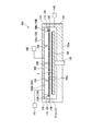
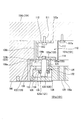
- FIG. 1 is a schematic cross-sectional view showing a vacuum processing apparatus according to this embodiment.
- reference numeral 100 is a vacuum processing apparatus.
- the vacuum processing apparatus 100 performs film formation on a substrate (substrate to be processed) S by a plasma CVD method.
- the vacuum processing apparatus 100 has a processing chamber 101 having a film forming space 101a which is a reaction chamber.
- the processing chamber 101 includes a vacuum chamber 102 (chamber), an electrode flange 104, and an insulating flange 103 sandwiched between the vacuum chamber 102 and the electrode flange 104.
- An opening is formed in the bottom portion 102a (inner bottom surface) of the vacuum chamber 102.
- a column 145 is inserted through this opening, and the column 145 is arranged in the lower portion of the vacuum chamber 102.
- a plate-shaped support portion (heater) 141 is connected to the tip of the column 145 (inside the vacuum chamber 102).
- the vacuum chamber 102 is provided with a vacuum pump (exhaust means) 148 via an exhaust pipe.
- the vacuum pump 148 reduces the pressure so that the inside of the vacuum chamber 102 is in a vacuum state.
- the column 145 is connected to an elevating mechanism (not shown) provided outside the vacuum chamber 102 and is vertically movable in the vertical direction of the substrate S.
- the electrode flange 104 has an upper wall 104a and a peripheral wall 104b.
- the electrode flange 104 is arranged such that the opening of the electrode flange 104 is located below the substrate S in the vertical direction.
- a shower plate 105 is attached to the opening of the electrode flange 104.
- a space 101b (gas introduction space) is formed between the electrode flange 104 and the shower plate 105.
- the upper wall 104 a of the electrode flange 104 faces the shower plate 105.
- a gas supply unit 142 (gas supply means) is connected to the upper wall 104a via a gas introduction port.
- the space 101b functions as a gas introduction space into which the process gas is introduced from the gas supply unit 142.
- the electrode flange 104 and the shower plate 105 are each made of a conductive material, and are made of metal such as aluminum.
- a shield cover is provided around the electrode flange 104 so as to cover the electrode flange 104.
- the shield cover is not in contact with the electrode flange 104 and is arranged so as to be continuous with the peripheral portion of the vacuum chamber 102.
- An RF power source 147 (high frequency power source) provided outside the vacuum chamber 102 is connected to the electrode flange 104 via a matching box.
- the matching box is attached to the shield cover, and the vacuum chamber 102 is grounded via the shield cover.
- the electrode flange 104 and the shower plate 105 are configured as a cathode electrode.
- the shower plate 105 is formed with a plurality of gas ejection ports 105a.
- the process gas introduced into the space 101b is ejected from the gas ejection port 105a to the film formation space 101a in the vacuum chamber 102.
- the electrode flange 104 and the shower plate 105 which are supplied with power from the RF power source 147, serve as cathode electrodes, plasma is generated in the film formation space 101a, and processing such as film formation is performed.
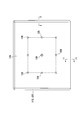
- FIG. 2 is a plan view of the shower plate 105 according to the present embodiment as viewed from above.
- the shower plate 105 is suspended and supported downward from the electrode flange 104 by a rod-shaped fixed shaft 109 and a movable shaft 108.
- the fixed shaft 109 is fixedly attached to the central position of the shower plate 105 in plan view.
- the movable shaft 108 is arranged at the apex of a rectangle centered on the fixed shaft 109 and the midpoint of the four sides.
- the movable shaft 108 has a structure that moves in accordance with the thermal expansion of the shower plate 105. Specifically, the movable shaft 108 is connected to the shower plate 105 via a spherical bush provided at the lower end of the movable shaft 108. The movable shaft 108 is capable of supporting the shower plate 105 while moving in accordance with the deformation of the shower plate 105 in the horizontal direction.
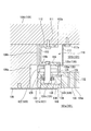
- FIG. 3 is an enlarged cross-sectional view showing a region including an edge portion of the shower plate 105 according to this embodiment.
- An insulating shield 106 is circumferentially provided outside the peripheral edge of the shower plate 105 so as to be separated from the edge of the shower plate 105.
- the insulating shield 106 is attached to the peripheral wall 104b of the electrode flange 104.
- a heat expansion absorption space (gap) 106a is formed at a position inside the insulating shield 106 and a position outside the peripheral end surface of the shower plate 105.
- FIG. 4 is an enlarged top view showing a region including a corner of the electrode frame 110 according to this embodiment. As shown in FIGS. 3 and 4, an electrode frame 110 and a slide plate 120 are provided around the upper edge of the shower plate 105.
- the electrode frame 110 is attached to the lower side of the peripheral wall 104b of the electrode flange 104 by a supporting member 111 such as a bolt.
- the electrode frame 110 is circumferentially provided inside the insulating shield 106.
- the electrode frame 110 is circumferentially provided at a position that is an outer contour of the gas introduction space 101b in plan view.
- the slide plate 120 is provided around the periphery of the shower plate 105 so as to substantially overlap the electrode frame 110 in plan view.
- the slide plate 120 is attached to the shower plate 105.
- the shower plate 105 and the electrode frame 110 are slidable.
- the edge of the shower plate 105 is suspended and supported by the electrode frame 110 by a stepped bolt (support member) 121.
- the stepped bolt 121 penetrates the shower plate 105 and the slide plate 120 from the lower side, and the tip thereof is fastened to the electrode frame 110.
- the slide plate 120 is located between the electrode frame 110 and the shower plate 105.
- the slide plate 120 can move in a direction parallel to the surface of the shower plate 105 integrally with the edge of the shower plate 105 in response to thermal deformation that occurs when the temperature of the shower plate 105 is raised or lowered.
- the electrode frame 110 moves so that the slide plate 120 slides and the slide position changes in response to thermal deformation of the shower plate 105 that occurs when the temperature of the shower plate 105 is raised or lowered.
- the electrode frame 110 and the slide plate 120 are sealing side walls of the gas introduction space 101b surrounded by the shower plate 105 and the electrode flange 104.
- the electrode frame 110 and the slide plate 120 are slidable between the slide plate 120 attached to the shower plate 105 and the electrode frame 110 attached to the electrode flange 104 corresponding to the slide plate 120. However, they remain in contact with each other.
- the electrode frame 110 and the slide plate 120 can seal the gas introduction space 101b even when they slide with each other.
- the electrode frame 110 and the slide plate 120 electrically connect the peripheral edge of the shower plate 105 and the electrode flange 104.
- the electrode frame 110 has a rectangular contour that is an outer contour that is substantially equal to the peripheral edge of the shower plate 105 in plan view.
- the electrode frame 110 also has substantially equal width dimensions around the shower plate 105.
- the electrode frame 110 is made of metal such as Hastelloy (registered trademark).
- the slide plate 120 has a rectangular contour which is substantially the same as the outer contour of the peripheral portion of the shower plate 105 in a plan view like the electrode frame 110.
- the slide plate 120 also has approximately equal width dimensions around the shower plate 105.
- the slide plate 120 may be made of the same material as the electrode frame 110, for example, a metal such as Hastelloy.
- the electrode frame 110 has an upper plate surface portion (fixed portion) 112, a vertical plate surface portion (wall portion) 113, and a lower plate surface portion (base portion) 114.
- the upper plate surface portion (fixed portion) 112 is fixedly attached to the lower surface of the electrode flange 104 facing the shower plate 105.
- the vertical plate surface portion (wall portion) 113 is erected from the entire periphery of the contour outer end portion of the upper plate surface portion (fixed portion) 112 toward the shower plate 105.
- the lower plate surface portion (base portion) 114 extends from the lower end of the vertical plate surface portion (wall portion) 113 substantially parallel to the upper plate surface portion (fixed portion) 112.
- the electrode frame 110 has an upper plate surface portion (fixed portion) 112, a vertical plate surface portion (wall portion) 113, and a lower plate surface portion (base portion) 114 so that the cross-sectional shape orthogonal to the contour of the shower plate 105 is U-shaped. Is formed in.
- the electrode frame 110 is formed by an upper plate surface portion (fixed portion) 112, a vertical plate surface portion (wall portion) 113, and a lower plate surface portion (base portion) 114 so as to have an internal space inside the U shape.
- the upper plate surface portion (fixed portion) 112 is attached to the peripheral wall 104b of the electrode flange 104 by a supporting member 111 such as a bolt.
- the support member 111 penetrates the upper plate surface portion (fixed portion) 112.
- the upper plate surface portion (fixed portion) 112 is located on the peripheral wall 104b side of the electrode flange 104 in the electrode frame 110, that is, on the low temperature side. As shown in FIGS. 3 and 4, the upper plate surface portion (fixed portion) 112 is provided with a notch 112a having a predetermined shape at an end portion (outside edge of the contour) toward the center of the gas introduction space 101b. The notch 112a is formed on the side opposite to the insulating shield 106 and prevents the electrode frame 110 from being deformed when the temperature of the electrode frame 110 rises or falls.
- the notch 112a is, for example, formed in an arc shape or a curved shape in a plan view, as shown in FIGS. 3 and 4. In the portion where the notch 112a is provided, the widthwise dimension of the electrode frame 110 in the upper plate surface portion (fixed portion) 112 becomes small.
- the notch 112a can also be provided in the vicinity of a corner portion of the shower plate 105 having a rectangular shape.
- the vertical plate surface portion (wall portion) 113 is erected substantially vertically from the electrode flange 104 toward the main surface of the shower plate 105.
- the upper end of the vertical plate surface portion (wall portion) 113 is connected to the end portion of the upper plate surface portion (fixed portion) 112 on the entire outer periphery of the contour of the electrode frame 110.
- the vertical plate surface portion (wall portion) 113 is arranged inside the insulating shield 106.
- the vertical plate surface portion (wall portion) 113 faces the inner peripheral surface of the insulating shield 106.
- the outer peripheral surface of the peripheral portion of the vertical plate surface portion (wall portion) 113 is separated from the inner peripheral surface of the insulating shield 106.
- a gap 106b is formed between the outer peripheral surface of the peripheral portion of the vertical plate surface portion (wall portion) 113 and the inner peripheral surface of the insulating shield 106.
- the electrode frame 110 is attached to the electrode flange 104 and is on the low temperature side. Therefore, the dimension of thermal expansion of the electrode frame 110 expected when the temperature is raised is smaller than the dimension of thermal expansion of the shower plate 105 and the slide plate 120 expected when the temperature is raised.
- the gap 106b is set smaller than the thermal expansion absorption space 106a. That is, the distance between the outer peripheral surface of the vertical plate surface portion (wall portion) 113 and the inner peripheral surface of the insulating shield 106 is set smaller than the distance between the outer peripheral end surface of the shower plate 105 and the inner peripheral side surface of the insulating shield 106.
- a step is formed on the inner peripheral surface of the insulating shield 106 so as to correspond to the gap 106b and the heat expansion absorption space 106a. This step is formed closer to the electrode frame 110 than the slip seal surface 114a, which is the contact position between the slide plate 120 and the electrode frame 110, and the slip seal surface 120a.
- the lower end of the vertical plate surface portion (wall portion) 113 is connected to the outer peripheral side end portion of the lower plate surface portion (base portion) 114.
- the lower plate surface portion (base portion) 114 is arranged from the lower end of the vertical plate surface portion (wall portion) 113 toward the center side of the gas introduction space 101b. That is, the lower plate surface portion (base portion) 114 extends from the lower end of the vertical plate surface portion (wall portion) 113 toward the inside of the contour of the electrode frame 110. The lower plate surface portion (base portion) 114 extends parallel to the upper plate surface portion (fixed portion) 112.
- the lower plate surface portion (base portion) 114 is on a higher temperature side than the upper plate surface portion (fixed portion) 112. Therefore, no cutout is provided to prevent deformation.
- the lower plate surface portion (base portion) 114 has substantially the same width dimension over the entire circumference of the shower plate 105.
- the plate thickness of the lower plate surface portion (base portion) 114 can be set to be larger than the plate thickness of the upper plate surface portion (fixed portion) 112.
- the lower surface of the lower plate surface portion (base portion) 114 on the shower plate 105 side is a slide seal surface 114 a that is parallel to the main surface of the shower plate 105.
- the slip seal surface 114 a is in contact with the slip seal surface 120 a provided on the upper surface of the slide plate 120.
- the slip seal surface 114a is the entire lower surface of the lower plate surface portion (base portion) 114 on the shower plate 105 side.
- a stepped bolt 121 is screwed from below to the lower plate surface portion (base portion) 114.
- a plate-shaped reflector 117 is provided on the entire inner circumference of the electrode frame 110.
- the reflectors 117 are provided at four locations in parallel with the contour sides of the shower plate 105 having a rectangular contour.
- the reflector 117 is arranged close to the inner peripheral side of the electrode frame 110.
- the reflector 117 is a metal plate bent in an L shape.
- the upper end of the reflector 117 is bent toward the center of the gas introduction space 101b.
- the bent portion at the upper end of the reflector 117 is attached to the peripheral wall 104b of the electrode flange 104 with a screw 117a.
- the outside of the upper end of the reflector 117 is arranged close to the inside end of the upper plate surface portion (fixed portion) 112 of the electrode frame 110.
- the lower end of the reflector 117 is located near the inner end of the lower plate surface portion (base portion) 114 of the electrode frame 110. Therefore, the reflector 117 is arranged so as to face the opening of the internal space of the U-shaped electrode frame 110 in a sectional view. The lower end of the reflector 117 and the inner end of the lower plate surface portion (base portion) 114 of the electrode frame 110 are not connected.
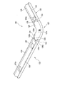
- FIG. 5 is an enlarged perspective view of a corner portion on the lower surface side of the slide plate 120 according to this embodiment.
- FIG. 6 is a bottom view showing the vicinity of a region including the peripheral portion of the shower plate 105 in this embodiment.
- the entire upper surface of the slide plate 120 serves as a slip seal surface 120a.
- the slide plate 120 has a configuration in which a plate body parallel to the upper surface of the shower plate 105 is formed in a frame shape having a substantially equal width. As shown in FIGS. 5 and 6, the slide plate 120 corresponds to the side slide portions 122 located corresponding to the four sides of the shower plate 105 having a substantially rectangular contour and the four corners of the shower plate 105. And a corner slide portion 127 located therein.
- the side slide portion 122 and the corner slide portion 127 have the same thickness dimension as shown in FIG. Both the side slide portion 122 and the corner slide portion 127 are attached to the upper surface of the shower plate 105.
- the corner slide portions 127 are respectively combined with the end portions of the side slide portions 122 extending on two adjacent sides of the shower plate 105.
- the corner slide portion 127 is fixed to the upper surface of the shower plate 105 with a fastening screw 127a.
- the side slide 122 is attached to the upper surface of the shower plate 105 by being sandwiched between the corner slide 127 fixed to the shower plate 105 and the shower plate 105 and the electrode frame 110. Further, the side slide portion 122 is regulated in position so as not to come off even by the stepped bolt 121 penetrating the through hole 125a, as described later.
- the corner slide portion 127 is provided with two labyrinth convex portions 128, 128 that respectively project toward the combined side slide portion 122.
- the labyrinth convex portion 128 projects in the direction along the contour side of the shower plate 105.
- the two labyrinth convex portions 128 of the corner slide portion 127 project in directions orthogonal to each other.
- the labyrinth convex portion 128 is arranged at the center in the width direction of the corner slide portion 127. That is, each of the two labyrinth convex portions 128 is arranged at the central position in the width direction of the slide plate 120 facing each other.
- the side slide portion 122 is provided with two labyrinth convex portions 123 and 124 that project toward the combined corner slide portion 127.
- the labyrinth convex portion 123 and the labyrinth convex portion 124 project in the direction along the contour side of the shower plate 105.
- the labyrinth convex portion 123 and the labyrinth convex portion 124 are formed in parallel with each other.
- the labyrinth convex portion 123 and the labyrinth convex portion 124 are arranged at both outer positions in the width direction of the slide plate 120 with respect to the labyrinth convex portion 128 of the corner slide portion 127.
- the labyrinth convex portion 123 and the labyrinth convex portion 124 are set to have the same dimension in the width direction of the slide plate 120.
- the width dimensions of the labyrinth convex portion 123 and the labyrinth convex portion 124 can both be set smaller than the width dimension of the labyrinth convex portion 128.
- the labyrinth convex portion 123 and the labyrinth convex portion 128 are in contact with each other. Further, the labyrinth convex portion 124 and the labyrinth convex portion 128 are in contact with each other.
- the inner side surface of the labyrinth convex portion 123 is a slip seal surface 123a
- the outer side surface of the labyrinth convex portion 128 is a slip seal surface 128a.
- the slip seal surface 123a and the slip seal surface 128a are in contact with each other.
- the outer side surface of the labyrinth convex portion 124 serves as a slip seal surface 124b
- the inner side surface of the labyrinth convex portion 128 serves as a slip seal surface 128b.
- the slip seal surface 124b and the slip seal surface 128b are in contact with each other.
- the inner side and the outer side mean positions inward and outward with respect to the gas introduction space 101b, that is, positions in the radial direction from the center in the plane of the shower plate 105.
- the slip seal surface 128a and the slip seal surface 128b are formed parallel to each other.
- the slip seal surface 123a and the slip seal surface 124b facing each other are formed in parallel to each other.
- the slip seal surface 128a, the slip seal surface 128b, the slip seal surface 123a, and the slip seal surface 124b are all formed in a direction parallel to the contour side of the shower plate 105.
- the slip seal surface 128a, the slip seal surface 128b, the slip seal surface 123a, and the slip seal surface 124b are all formed in the vertical direction.
- the upper ends of the slip seal surface 128a, the slip seal surface 128b, the slip seal surface 123a, and the slip seal surface 124b are in contact with the electrode frame 110.
- the lower ends of the sliding seal surface 128a, the sliding seal surface 128b, the sliding seal surface 123a, and the sliding seal surface 124b are in contact with the shower plate 105.
- the labyrinth convex portion 123 of the side slide portion 122, the labyrinth convex portion 128 of the corner slide portion 127, and the labyrinth convex portion 124 of the side slide portion 122 are arranged in the contour direction of the gas introduction space 101b. That is, the labyrinth convex portion 123, the labyrinth convex portion 128, and the labyrinth convex portion 124 are alternately arranged in the contour direction of the gas introduction space 101b so as to be multi-tiered from the inside to the outside of the gas introduction space 101b. ..
- the labyrinth convex portion 124 and the labyrinth convex portion 128 maintain the contact state. .. Since the slip seal surface 124b and the slip seal surface 128b are not separated from each other in this manner, the seal at this portion is maintained.
- the labyrinth convex portion 128 and the labyrinth convex portion 123 maintain the contact state. .. Since the slip seal surface 128a and the slip seal surface 123a are not separated from each other in this manner, the seal at this portion is maintained.
- the labyrinth convex portions 128 of the corner slide portion 127 slide while being sandwiched between the labyrinth convex portions 123 and the labyrinth convex portions 124 of the side slide portions 122 located on both sides thereof.
- the slip seal surface 124b and the slip seal surface 128b are not separated from each other.
- the slip seal surface 128a and the slip seal surface 123a are not separated from each other.
- the sealed state at the side wall portion of the gas introduction space 101b can be maintained regardless of the temperature state.
- the slide plate 120 is provided with a recessed groove 125 in a portion contacting the shower plate 105, that is, in the lower surface of the slide plate 120.
- the concave groove 125 is formed such that the leg portion 126 abutting the shower plate 105 is located on the entire circumference of the side slide portion 122.
- the depth dimension of the groove 125 can be arbitrarily set as long as it is smaller than the thickness dimension of the slide plate 120 and the strength of the slide plate 120 is not reduced.
- the width dimension of the leg portion 126, that is, the width direction dimension of the slide plate 120 is preferably as small as possible as long as the strength of the slide plate 120 is not reduced.
- the concave groove 125 By forming the concave groove 125, the area of the slide plate 120 that contacts the shower plate 105 can be reduced. Thereby, the cross-sectional area of the heat transfer path from the shower plate 105 to the slide plate 120 can be reduced.
- the concave groove 125 is formed in the side slide portion 122.
- the concave groove may be formed in the corner slide portion 127.
- a concave groove may be formed so that the leg portion that abuts the shower plate 105 is located all around the corner slide portion 127. Further, in this case, in the corner slide portion 127, the labyrinth convex portion 128 can also be formed with a concave groove.
- a through hole 125a is provided inside the groove 125.
- the through hole 125a penetrates the slide plate 120.
- a plurality of through holes 125a are provided in the direction in which the side slide portion 122 extends. The plurality of through holes 125a are arranged apart from each other.
- the stepped bolt 121 penetrates through the through hole 125a.
- the diameter of the through hole 125a is set larger than the diameter of the stepped bolt 121.
- the contour shape of the through hole 125a corresponds to an elongated hole 131 described later.
- the shape in which the through hole 125a corresponds to the elongated hole 131 means that the shaft portion 121b of the stepped bolt 121 can slide without trouble in response to thermal deformation that occurs when the temperature of the shower plate 105 is raised or lowered, as described later. It means that it has a simple shape. That is, it means that the through hole 125a has a shape that does not affect the relative movement of the stepped bolt 121 inside the elongated hole 131.
- the diameter of the through hole 125a is larger than the long axis of the long hole 131. That is, when the through hole 125a is formed to be larger than the elongated hole 131 in plan view, it does not come into contact with the shaft portion 121b of the stepped bolt 121 that relatively moves inside the elongated hole 131. Further, the outline shape of the through hole 125a is not particularly limited as long as the above dimensions are satisfied.
- the lower surface of the shower plate 105 is provided with a hanging groove 130 at the peripheral edge of the shower plate 105.
- a plurality of suspension grooves 130 are provided at the peripheral edge of the shower plate 105 at predetermined intervals.
- An elongated hole 131 that penetrates the shower plate 105 in the thickness direction is provided inside the hanging groove 130.
- the hanging groove 130 is formed as an enlarged shape of the elongated hole 131.
- the shaft portion 121 b of the stepped bolt 121 penetrates the long hole 131 and is fixed to the electrode frame 110.
- the elongated hole 131 is formed long in the direction of thermal deformation of the shower plate 105 so that the shaft portion 121b of the stepped bolt 121 can slide in response to thermal deformation of the shower plate 105 when the temperature of the shower plate 105 is increased or decreased.
- the long hole 131 has a long axis parallel to a straight line radially drawn from the fixed shaft 109 which is the central position when the shower plate 105 is viewed in plan. Therefore, the elongated hole 131 is an ellipse (rounded rectangle) having major axes in different tilt directions depending on the position where the elongated hole 131 is arranged.
- the long hole 131 has an opening dimension in the long axis direction set to be longer than the distance over which the shaft portion 121b of the stepped bolt 121 relatively moves, corresponding to the thermal deformation that occurs when the shower plate 105 is heated and lowered. Therefore, the dimension of the long hole 131 in the long axis direction needs to be appropriately changed depending on the dimension of the shower plate 105 and the coefficient of thermal expansion defined by the material.
- the opening dimension of the long hole 131 in the minor axis direction may be slightly larger than the outer diameter dimension of the shaft portion 121b of the stepped bolt 121.
- a long slide member (long washer) 132 is arranged at the opening of the long hole 131 on the suspension groove 130 side.
- the shaft portion 121b of the stepped bolt 121 penetrates the long slide member 132.
- the long slide member 132 has a contour shape that is the same as or slightly smaller than the hanging groove 130.
- the long slide member 132 has an opening shape that is similar to or slightly smaller than the long hole 131.
- the opening diameter dimension of the long slide member 132 in the minor axis direction is set to be the same as or slightly smaller than the opening diameter dimension of the elongated hole 131 in the minor axis direction.
- the opening diameter dimension of the long slide member 132 in the long axis direction is set to be the same as or slightly smaller than the opening diameter dimension of the long hole 131 in the long axis direction.
- a bolt head 121 a of the stepped bolt 121 is located below the long slide member 132. Between the long slide member 132 and the bolt head 121a, a slide member (washer) 133 and disc springs 134 and 135 are stacked and arranged from above. The shaft portion 121b of the stepped bolt 121 penetrates through the slide member 133 and the disc springs 134 and 135.
- the opening diameter dimension of the long slide member 132 in the minor axis direction is set smaller than the outer diameter dimension of the bolt head 121a of the stepped bolt 121.
- the opening diameter dimension of the long slide member 132 in the short axis direction is set smaller than the outer diameter dimension of the slide member 133.
- the outer diameter dimension of the slide member 133 is set to be the same as or slightly larger than the outer diameter dimension of the bolt head 121a. Further, the outer diameter dimension of the slide member 133 is set to be larger than the opening diameter dimension of the long slide member 132 in the short axis direction.
- the inner diameters of the slide member 133 and the disc springs 134 and 135 are set to be the same as or slightly larger than the outer diameters of the shaft portion 121b of the stepped bolt 121.
- the slide member 133 and the disc springs 134 and 135 follow the slide of the stepped bolt 121 which is slidable inside the suspension groove 130.
- the long slide member 132 and the slide member 133 are slidably in contact with each other.
- the slide member 133 slides with the long slide member 132 located below the periphery of the long hole 131 inside the hanging groove 130.
- the relationship among the opening dimension of the long hole 131 in the short axis direction, the opening dimension of the long slide member 132 in the short axis direction, the outer diameter dimension of the slide member 133, and the outer diameter dimension of the bolt head 121a is as described above in order from the top. Is set.
- the long slide member 132 can be regulated so as not to move to the concave groove 125 side from the opening of the long hole 131.
- the slide member 133 can be regulated so as not to move from the opening of the long slide member 132 to the concave groove 125 side.
- the bolt head 121a can be regulated so as not to move in the vertical direction with respect to the slide member 133.
- the long slide member 132 and the slide member 133 regulate the position of the bolt head 121a so as not to move to the electrode frame 110 side. That is, the bolt head 121a of the stepped bolt 121 can be restricted so as not to come out toward the concave groove 125 side. Accordingly, the long slide member 132 and the slide member 133 are regulated so that the position of the bolt head 121a in the axial direction of the stepped bolt 121 is constant.
- the long slide member 132 and the slide member 133 slide while maintaining the suspended state of the shower plate 105 by the stepped bolt 121. Accordingly, the step height 121 of the shower plate 105 can be maintained and the stepped bolt 121 can slide inside the hanging groove 130.
- the long slide member 132 and the slide member 133 can be made of the same material as the slide plate 120. Specifically, the long slide member 132 and the slide member 133 can be made of a metal such as Hastelloy.
- the disc springs 134 and 135 are attached so as to urge the bolt head 121a of the stepped bolt 121 downward.
- the disc springs 134 and 135 follow the sliding movement of the shaft portion 121b of the stepped bolt 121 in response to thermal deformation that occurs when the temperature of the shower plate 105 is increased or decreased, and the disc springs of the suspension groove 130 are formed. It is supposed to be movable inside. At this time, the biased state of the disc springs 134 and 135 against the bolt head 121a and the slide member 133 is maintained.
- the disc springs 134 and 135 may be provided in a plural number, and the number thereof is not limited.
- the slide member 133 and the disc springs 134 and 135 can be made of an elastic material such as Inconel (registered trademark).
- a lid 136 is provided at the lower opening position of the hanging groove 130.
- the lower opening of the hanging groove 130 is closed by a lid 136.
- the opening side of the hanging groove 130 of the lid 136 is flush with the lower surface of the shower plate 105.
- the opening side of the hanging groove 130 may be located slightly below the lower surface of the shower plate 105.
- FIG. 6 the long slide member 132, the slide member 133, the disc springs 134 and 135, and the lid 136 are not shown. Further, in FIG. 6, main parts such as the slide plate 120 and the electrode frame 110 are shown by broken lines.
- FIG. 7 is an enlarged cross-sectional view of the vicinity of the edge of the shower plate 105 in the thermally expanded state of the present embodiment.
- FIG. 8 is a bottom view showing a region including a peripheral portion of the shower plate 105 in the thermally expanded state of the present embodiment.
- the peripheral portion of the shower plate 105 that has been thermally expanded does not contact the insulating shield 106 by expanding to the thermal expansion absorption space 106a. Therefore, the expansion of the shower plate 105 is absorbed so as not to give stress to the electrode flange 104, the electrode frame 110, the insulating shield 106 and the like. At this time, the movable shaft 108 can support the deformed shower plate 105 by the spherical bush at the lower end.
- the slide plate 120 fixed to the peripheral portion of the thermally expanded shower plate 105 moves as a unit toward the outer periphery of the shower plate 105.
- the peripheral portion of the shower plate 105 and the slide plate 120 also move so as to narrow the heat expansion absorption space 106a (see FIG. 7), as indicated by the arrow in FIG. Since the slide plate 120 does not contact the insulating shield 106, the movement of the slide plate 120 is absorbed so as not to give stress to the electrode flange 104, the electrode frame 110, the insulating shield 106 and the like.
- the slide plate 120 moves toward the outer periphery of the shower plate 105
- the slide plate 120 and the shower plate 105 integrally move toward the outer periphery of the shower plate 105.
- the electrode frame 110 is fixed to the electrode flange 104, the relative position with respect to the electrode flange 104 and the insulating shield 106 does not change so much.
- the electrode frame 110 is not deformed, and the sliding seal surface 114a of the electrode frame 110 and the sliding seal surface 120a of the slide plate 120 slide, and the shower plate 105 is in a heat expansion state while maintaining the sealing state. Become.
- the stepped bolt 121 is fixed to the electrode frame 110. Therefore, the relative position of the stepped bolt 121 with respect to the electrode flange 104 and the insulating shield 106 does not change so much.
- the elongated hole 131 and the hanging groove 130 also move toward the outer periphery of the shower plate 105.
- the stepped bolt 121 relatively moves in the long axis direction of the long hole 131.
- the long axis direction of the long hole 131 coincides with the thermal deformation direction that occurs when the temperature of the shower plate 105 is increased or decreased. Therefore, the shaft portion 121b of the stepped bolt 121 can slide inside the elongated hole 131 in response to thermal deformation that occurs when the temperature of the shower plate 105 is raised or lowered. Therefore, the movement of the stepped bolt 121 is absorbed so as not to give stress to the shower plate 105 and the stepped bolt 121 located near the elongated hole 131.
- the through hole 125 a of the slide plate 120 also moves toward the outer periphery of the shower plate 105.
- the stepped bolt 121 moves relative to the through hole 125a.
- the shaft portion 121b of the stepped bolt 121 can slide inside the through hole 125a in response to thermal deformation that occurs when the shower plate 105 is heated or cooled. is there. Therefore, the movement of the stepped bolt 121 is absorbed so as not to give stress to the slide plate 120 and the stepped bolt 121 located in the vicinity of the through hole 125a. As a result, the suspension support of the stepped bolt 121 of the shower plate 105 with respect to the electrode frame 110 is maintained.
- the sliding seal surface 114a of the lower plate surface portion (base portion) 114 of the electrode frame 110 and the sliding seal surface 120a of the slide plate 120 are slidable in the thermal expansion direction of the shower plate 105. .. Therefore, even during thermal expansion, the contact state is maintained without being deformed, so that the seal state and the load supporting state of the shower plate 105 can be maintained.
- the electrode frame 110 and the slide plate 120 are made of the same material, Hastelloy, it is possible to suppress the generation of particles due to the scraping of the members. Therefore, it is possible to prevent the film thickness characteristics of the vacuum processing apparatus 100 from being deteriorated.
- the corner slide portion 127 that slidably seals the end portions of the side slide portions 122 of the slide plate 120. Is provided.
- the side slide portion 122 fixed to the peripheral edge of the shower plate 105 and the corner slide portion 127 are separated in the linear direction along the contour side of the shower plate 105.
- the labyrinth convex portion 123 and the labyrinth convex portion 124 of the side slide portion 122 and the labyrinth convex portion 128 of the corner slide portion 127 are separated from each other.
- the sliding seal surface 123a and the sliding seal surface 128a, and the sliding seal surface 124b and the sliding seal surface 128b respectively slide in the direction along the contour line of the shower plate 105, thereby maintaining the sealed state,
- the side slide portion 122 and the corner slide portion 127 can be separated from each other.
- the side slide part 122 and the corner slide part 127 having the labyrinth structure as described above can prevent gas leakage in the shower plate 105 and maintain the sealed state of the gas introduction space 101b.
- the groove 125 is formed in the slide plate 120, and the portion corresponding to the groove 125 is not in contact with the shower plate 105. Therefore, the heat transfer path is reduced by the area corresponding to the groove 125. Therefore, the amount of heat conducted from the shower plate 105 to the slide plate 120 is reduced.
- the lower surface of the lower plate surface portion (base portion) 114 contacts the slide plate 120 that is the high temperature side.
- the portion extending in the up-down direction is the vertical plate surface portion (wall portion) 113 to form an internal space having a U-shaped cross section.
- a portion corresponding to the plate thickness of the vertical plate surface portion (wall portion) 113 with respect to the area of the lower plate surface portion (base portion) 114 is a heat transfer path. Therefore, the heat transfer path is reduced by the area corresponding to the U-shaped internal space of the electrode frame 110. Therefore, the amount of heat conducted from the slide plate 120 to the electrode flange 104 is reduced.
- the heat insulation between the electrode frame 110 and the slide plate 120 can be improved.
- the heat flux in the path from the shower plate 105 to the peripheral wall 104b of the electrode flange 104 via the slide plate 120 and the electrode frame 110 can be reduced.
- the pressure inside the vacuum chamber 102 is reduced using the vacuum pump 148.
- the substrate S is loaded from the outside of the vacuum chamber 102 toward the film formation space 101a with the inside of the vacuum chamber 102 maintained at a vacuum.
- the substrate S is placed on the support portion (heater) 141.
- the support 145 is pushed upward, and the substrate S placed on the support (heater) 141 also moves upward.
- the distance between the shower plate 105 and the substrate S is determined as desired so as to be the distance required for proper film formation, and this distance is maintained.
- the process gas is introduced from the gas supply unit 142 into the gas introduction space 101b via the gas introduction pipe and the gas introduction port. Then, the process gas is ejected from the gas ejection port 105a of the shower plate 105 into the film formation space 101a.
- the RF power source 147 is activated to apply high frequency power to the electrode flange 104. Then, a high-frequency current flows from the surface of the electrode flange 104 along the surface of the shower plate 105, and a discharge is generated between the shower plate 105 and the support portion (heater) 141. Then, plasma is generated between the shower plate 105 and the processing surface of the substrate S.
- the process gas is decomposed in the plasma thus generated, a process gas in a plasma state is obtained, a vapor phase growth reaction occurs on the processing surface of the substrate S, and a thin film is formed on the processing surface.
- the shower plate 105 thermally expands (thermally deforms), but the electrode frame 110 and the slide plate 120 maintain a sealed state, and the gas is introduced from the gas introduction space 101b through a portion other than the gas ejection port 105a. Leakage into the film formation space 101a can be reduced. Further, since there is no component that is forcibly deformed due to the thermal expansion of the shower plate 105, it is possible to extend the life of the component.
- the shower plate 105 is thermally shrunk (heat-deformed), but the electrode frame 110 and the slide plate 120 maintain a sealed state, and the gas introduction space 101b except the gas ejection port 105a. It is possible to reduce leakage through the film formation space 101a. Further, since there is no part that is forcibly deformed due to the thermal contraction of the shower plate 105, the life of the part can be extended.
- the labyrinth convex portions 128 and 128 that respectively project toward the combined side slide portion 122 are provided in the corner slide portion 127, but as shown in FIG.
- the labyrinth convex portion 128 may be provided on the side slide portion 122 so as to face the corner slide portion 127.
- the side slide portion 122 and the corner slide portion 127 can slide while maintaining a sealed state in response to thermal deformation that occurs when the shower plate 105 is heated and lowered.
- the labyrinth convex portion 128 is arranged only on the one side slide portion 122, but the labyrinth convex portion 128 on both sides may be arranged.
- Example 1 In the vacuum processing apparatus 100 in the above-described embodiment, the formation of an oxide film, particularly the formation of SiO x by TEOS (tetraethoxysilane) having a large molecular weight as a raw material gas, was examined.
- TEOS tetraethoxysilane
- ⁇ Substrate heating temperature 430°C -Substrate to be processed
- S dimension 1500 x 1800 mm ⁇ Width dimension of slide plate 120: 35 mm ⁇ Thickness of slide plate 120: 10 mm ⁇ Depth of the groove 125; 5mm ⁇ Width of leg 126: 3 mm ⁇ Height dimension of the electrode frame 110: 32.5 mm ⁇ Thickness of vertical plate surface 113: 3 mm
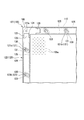
- FIG. 9 shows the temperature distribution simulation results for the shower plate.
- a quarter of the shower plate is shown. That is, the lower left is the center position of the shower plate.
- the maximum temperature in the shower plate 105 is 431.99° C.
- the minimum temperature is 398.75° C.
- the in-plane temperature distribution ⁇ 33.24° C. I understand.
- the width dimension is the same, the slide plate and the electrode frame in the above-described embodiment are integrally formed, and the device has a dense bulk-structured electrode frame having no groove or space. ..
- FIG. 10 shows a temperature distribution simulation result in the shower plate.
- a quarter of the shower plate is shown. That is, the lower left is the center position of the shower plate.
- the maximum temperature in the shower plate is 423.15° C.
- the minimum temperature is 338.16° C.
- the in-plane temperature distribution ⁇ 84.99° C. ..
- the stress distribution in SiN can be improved by improving the in-plane temperature distribution in the shower plate 105.
- a plasma processing apparatus for performing film formation as plasma processing, particularly plasma CVD, or surface processing of a substrate such as etching can be cited.
- Vacuum processing apparatus 101... Processing chamber 101a... Film forming space 101b... Space (gas introduction space) 102... Vacuum chamber 103... Insulation flange 104... Electrode flange 104a... Upper wall (electrode flange) 104b... peripheral wall (electrode flange) 105... Shower plate 105a... Gas ejection port 106... Insulation shield 106a... Thermal expansion absorption space (gap) 106b... Gap 108... Movable shaft 109... Fixed shaft 110... Electrode frame 111... Support member 112... Upper plate surface part (fixed part) 112a... Notch 113... Vertical plate surface portion (wall portion) 114...
Landscapes
- Chemical & Material Sciences (AREA)
- Engineering & Computer Science (AREA)
- Physics & Mathematics (AREA)
- Plasma & Fusion (AREA)
- Analytical Chemistry (AREA)
- Metallurgy (AREA)
- Materials Engineering (AREA)
- Mechanical Engineering (AREA)
- Chemical Kinetics & Catalysis (AREA)
- Organic Chemistry (AREA)
- General Chemical & Material Sciences (AREA)
- Electromagnetism (AREA)
- Spectroscopy & Molecular Physics (AREA)
- Plasma Technology (AREA)
- Chemical Vapour Deposition (AREA)
- Drying Of Semiconductors (AREA)
Abstract
Description
本願は、2019年1月7日に日本に出願された特願2019-000528号に基づき優先権を主張し、その内容をここに援用する。
電極フランジには、高周波電源が接続されている。電極フランジおよびシャワープレートは、カソード電極として機能する。
特許文献1、2には、シャワープレートの周囲が、電極フランジに直接接続された構成が記載されている。
1.シャワープレートまわりからのガス漏れを防止するガスシールの向上を図ること。
2.大面積を有するシャワープレートの熱伸縮に起因した問題を解消する処理装置を提供すること。
3.シャワープレートの温度が400℃を越えるような処理をおこなう処理装置において、処理温度の上昇を許容できる処理装置を提供すること。
4.シャワープレートにおける温度分布の向上を図ること。
本発明の真空処理装置は、前記スライドプレートには、前記シャワープレートに当接する部分に凹溝が形成されていることができる。
本発明において、前記スライドプレートは、略矩形輪郭とされる前記シャワープレートの辺に対応した辺スライド部と、前記シャワープレートの角に対応した角スライド部と、を有し、前記辺スライド部と前記角スライド部とが、前記シャワープレートの辺と平行なすべりシール面により互いに接触し、前記すべりシール面を介して、前記辺スライド部と前記角スライド部とが、前記シャワープレートの昇降温時に生じる熱変形に対応してシール状態を維持したままスライド可能とされることが好ましい。
本発明の真空処理装置は、前記辺スライド部と前記角スライド部とにおいて、前記すべりシール面の上端が前記電極枠に接し、前記すべりシール面の下端が前記シャワープレートに接していることが可能である。
また、本発明において、前記電極枠の内周側には、前記電極枠の全周に沿う板状のリフレクタが設けられ、前記リフレクタの上端が、前記電極フランジに取り付けられ、前記リフレクタの下端が、前記下板面部の内側端付近に位置する手段を採用することもできる。
本発明の真空処理装置は、前記シャワープレートが、前記シャワープレートに設けられた長穴を貫通する支持部材によって前記電極枠に支持され、前記長穴は、前記支持部材が前記シャワープレートの昇降温時に生じる熱変形に対応してスライド可能なように、前記シャワープレートの昇降温時に生じる熱変形方向に長く形成されることができる。
また、本発明の真空処理装置は、前記シャワープレートおよび前記スライドプレートの周端面と、前記絶縁シールドとの間には、前記シャワープレートが熱伸び可能とする隙間部が設けられることができる。
これにより、部品変形の発生を防止することができる。
これにより、部品変形の発生を防止することができる。
このとき、辺スライド部と角スライド部とは、互いに離間するようにスライドする。また、辺スライド部のすべりシール面と角スライド部のすべりシール面とは、互いに接触した状態を維持したままスライドする。
これにより、スライドプレートにおける変形の発生を防止することができる。
これにより、スライドプレートにおける変形の発生を防止することができる。
これにより、シャワープレートが熱伸びした際に、隙間部でシャワープレートの膨張変形を吸収して、各部材における余計な応力が発生することなくシール状態を維持することができる。
図1は、本実施形態における真空処理装置を示す模式断面図であり、図1において、符号100は、真空処理装置である。
本実施形態に係る真空処理装置100は、プラズマCVD法による基板(被処理基板)Sへの成膜をおこなうものとされる。
また、支柱145は、真空チャンバ102の外部に設けられた昇降機構(不図示)に接続されており、基板Sの鉛直方向において上下に移動可能である。
電極フランジ104とシャワープレート105は、それぞれ導電材で構成されており、例えば、アルミニウム等の金属製とされる。
シャワープレート105は、棒状の固定シャフト109、可動シャフト108によって電極フランジ104から下向きに吊り下げられて支持されている。
シャワープレート105の周縁部の外側位置には、このシャワープレート105の縁部と離間するように絶縁シールド106が周設されている。絶縁シールド106は、電極フランジ104の周壁104bに取り付けられている。絶縁シールド106の内側位置と、シャワープレート105の周端面の外側位置とには、熱伸び吸収空間(隙間部)106aが形成されている。
シャワープレート105の周縁部上側には、図3、図4に示すように、電極枠110とスライドプレート120とが周設される。
段付きボルト121は、下側からシャワープレート105およびスライドプレート120を貫通して、その先端が電極枠110に締結される。
電極枠110とスライドプレート120とは、シャワープレート105と電極フランジ104とで囲まれるガス導入空間101bのシール側壁となっている。
電極枠110とスライドプレート120とは、シャワープレート105の周縁部と電極フランジ104とを電気的に接続している。
上板面部(固定部)112は、電極フランジ104におけるシャワープレート105に対向する下面に固定して取り付けられる。
下板面部(基部)114は、縦板面部(壁部)113の下端から上板面部(固定部)112と略平行に延在する。
切欠112aは、絶縁シールド106と反対側に形成され、電極枠110に温度の昇降が発生した時に、電極枠110の変形を防止する。
縦板面部(壁部)113は、絶縁シールド106の内側に配置される。縦板面部(壁部)113は、絶縁シールド106の内周面と対向している。
縦板面部(壁部)113の下端は、下板面部(基部)114の外周側端部に接続されている。
下板面部(基部)114のシャワープレート105側となる下面は、シャワープレート105の主面と並行なすべりシール面114aとされている。
すべりシール面114aは、下板面部(基部)114のシャワープレート105側となる下面の全域とされる。
したがって、リフレクタ117は、断面視においてU字状とされた電極枠110の内部空間の開口に対向するように配置される。なお、リフレクタ117の下端と、電極枠110の下板面部(基部)114の内側端とは、接続されていない。
図6は、本実施形態におけるシャワープレート105の周縁部を含む領域付近を示す下面図である。
スライドプレート120の上面は、その全域がすべりシール面120aとされる。
スライドプレート120は、図5、図6に示すように、略矩形輪郭とされるシャワープレート105の四辺に対応して位置する辺スライド部122と、シャワープレート105の四隅(コーナー)に対応して位置する角スライド部127と、を有する。
角スライド部127は、締結ネジ127aによってシャワープレート105の上面に固定されている。
ラビリンス凸部124の外側面は、すべりシール面124bとされ、ラビリンス凸部128の内側面は、すべりシール面128bとされる。すべりシール面124bとすべりシール面128bとは、互いに接触している。
また、辺スライド部122の一端に設けられた二本のラビリンス凸部123およびラビリンス凸部124では、互いに対向するすべりシール面123aとすべりシール面124bとが互いに平行に形成される。
すべりシール面128aとすべりシール面128bとすべりシール面123aとすべりシール面124bとは、いずれも上端が電極枠110に接する。すべりシール面128aとすべりシール面128bとすべりシール面123aとすべりシール面124bとは、いずれも下端がシャワープレート105に接する。
つまり、ラビリンス凸部123とラビリンス凸部128とラビリンス凸部124とが、ガス導入空間101bの内側から外側に向けて多段となるように、ガス導入空間101bの輪郭方向に互い違いに配置されている。
このようにすべりシール面124bとすべりシール面128bとが離間しないため、この部分のシールは維持される。
このようにすべりシール面128aとすべりシール面123aとが離間しないため、この部分のシールは維持される。
これにより、すべりシール面124bとすべりシール面128bとが離間することがない。同時に、すべりシール面128aとすべりシール面123aとが離間することがない。
凹溝125は、辺スライド部122の全周にシャワープレート105に当接する脚部126が位置するように形成される。
脚部126に幅寸法、つまり、スライドプレート120の幅方向寸法は、スライドプレート120の強度が低下しない程度であれば、なるべく小さくすることが好ましい。
貫通孔125aの径寸法は、段付きボルト121の径寸法よりも大きく設定される。貫通孔125aの輪郭形状は、後述する長穴131に対応する。
また、上記の寸法を満たしていれば、貫通孔125aの輪郭形状は特に限定されない。
吊り下げ溝130は、シャワープレート105の周縁部に所定の間隔で複数設けられる。
吊り下げ溝130の内部には、シャワープレート105を厚さ方向に貫通する長穴131が設けられる。
吊り下げ溝130は、長穴131を拡大した形状として形成される。
長穴131は、シャワープレート105の昇降温時に生じる熱変形に対応して、段付きボルト121の軸部121bがスライド可能なように、前記シャワープレートの昇降温時に生じる熱変形方向に長く形成される。
スライド部材133、皿バネ134、135には、段付きボルト121の軸部121bが貫通している。
また、長スライド部材132の短軸方向における開口径寸法は、スライド部材133の外径寸法よりも小さく設定される。
スライド部材133、皿バネ134、135の内径寸法は、段付きボルト121の軸部121bの外径寸法と同じかやや大きく設定される。
長スライド部材132とスライド部材133とは、スライド可能として互いに接している。
つまり、段付きボルト121のボルトヘッド121aが凹溝125側に抜けないように規制できる。
これにより、長スライド部材132とスライド部材133とは、段付きボルト121の軸方向におけるボルトヘッド121aの位置が一定となるように規制している。
後述する装置使用時には、加温されるためシャワープレート105が熱伸び(熱変形)する。この熱伸び時には、図7、図8に矢印で示すように、シャワープレート105が固定シャフト109を中心として面内方向外向きに膨張する。
このとき、可動シャフト108は、下端の球面ブシュによって、変形したシャワープレート105を支持可能となっている。
スライドプレート120は、絶縁シールド106に当接しないため、スライドプレート120の移動が電極フランジ104、電極枠110や絶縁シールド106等に応力を与えないように吸収される。
これにより、段付きボルト121は、長穴131の長軸方向に相対移動する。
したがって、段付きボルト121の移動は、長穴131の近傍に位置するシャワープレート105および段付きボルト121に応力を与えないように吸収される。
これにより、段付きボルト121は、貫通孔125aに対して相対移動する。
これにより、電極枠110に対するシャワープレート105の段付きボルト121の吊り下げ支持は、維持される。
このため、真空処理装置100における膜厚特性の悪化を防止することが可能となる。
このとき、すべりシール面123aとすべりシール面128a、すべりシール面124bとすべりシール面128bが、それぞれ、シャワープレート105輪郭辺直線に沿った方向に摺動することで、シール状態を維持したまま、辺スライド部122と角スライド部127とが離間することができる。
ここで、伝熱経路であるスライドプレート120では、脚部126がシャワープレート105に当接する。
同時に、シャワープレート105からスライドプレート120および電極枠110を経て電極フランジ104の周壁104bへと至る経路における熱流束を低減することができる。
このため、真空処理装置100における膜厚分布の悪化を防止するとともに、膜厚特性を向上することが可能となる。
すると、電極フランジ104の表面からシャワープレート105の表面を伝って高周波電流が流れ、シャワープレート105と支持部(ヒータ)141との間に放電が生じる。
そして、シャワープレート105と基板Sの処理面との間にプラズマが発生する。
この構成においても、辺スライド部122と角スライド部127とが、シャワープレート105の昇降温時に生じる熱変形に対応してシール状態を維持したままスライド可能となる。
なお、図11においては、片方の辺スライド部122のみにラビリンス凸部128を配置したが、両方の辺スライド部122ラビリンス凸部128を配置することもできる。
上述した実施形態における真空処理装置100において、酸化膜の成膜、特に、原料ガスとして分子量の多いTEOS(テトラエトキシシラン)によるSiOxの成膜について検討した。
・基板加熱温度;430℃
・被処理基板S寸法;1500×1800mm
・スライドプレート120の幅寸法;35mm
・スライドプレート120の厚さ寸法;10mm
・凹溝125の深さ寸法;5mm
・脚部126の幅寸法;3mm
・電極枠110の高さ寸法;32.5mm
・縦板面部113の厚さ寸法;3mm
図9では、シャワープレートの四分の一を示す。つまり、左下がシャワープレートの中央位置である。
実験例1と同様に、TEOS(テトラエトキシシラン)によるSiOxの成膜について検討した。
図10では、シャワープレートの四分の一を示す。つまり、左下がシャワープレートの中央位置である。
101…処理室
101a…成膜空間
101b…空間(ガス導入空間)
102…真空チャンバ
103…絶縁フランジ
104…電極フランジ
104a…上壁(電極フランジ)
104b…周壁(電極フランジ)
105…シャワープレート
105a…ガス噴出口
106…絶縁シールド
106a…熱伸び吸収空間(隙間部)
106b…隙間
108…可動シャフト
109…固定シャフト
110…電極枠
111…支持部材
112…上板面部(固定部)
112a…切欠
113…縦板面部(壁部)
114…下板面部(基部)
114a、120a、123a、124b、128a、128b…すべりシール面
117…リフレクタ
117a…ネジ
120…スライドプレート
121…段付きボルト(支持部材)
121a…ボルトヘッド
121b…軸部
122…辺スライド部
123、124、128…ラビリンス凸部
125…凹溝
125a…貫通孔
126…脚部
127…角スライド部
127a…締結ネジ
130…吊り下げ溝
131…長穴
132…長スライド部材(長ワッシャ)
133…スライド部材(ワッシャ)
134、135…皿バネ
136…蓋部
141…支持部(ヒータ)
142…ガス供給部(ガス供給手段)
145…支柱
147…RF電源(高周波電源)
148…真空ポンプ(排気手段)
S…基板(被処理基板)
Claims (7)
- プラズマ処理をおこなう真空処理装置であって、
高周波電源に接続された電極フランジと、
前記電極フランジと離間して対向し前記電極フランジとともにカソードとされるシャワープレートと、
前記シャワープレートの周囲に設けられた絶縁シールドと、
前記シャワープレートにおける前記電極フランジと反対側で被処理基板が配置される処理室と、
前記電極フランジの前記シャワープレート側に取り付けられる電極枠と、前記シャワープレートの前記電極枠側となる周縁部に取り付けられるスライドプレートと、
を有し、
前記シャワープレートが略矩形輪郭を有するように形成され、
前記電極枠と前記スライドプレートとが、前記シャワープレートの昇降温時に生じる熱変形に対応してスライド可能であり、かつ、前記シャワープレートと前記電極フランジと前記電極枠とで囲まれる空間がシール可能であり、
前記電極枠が、
前記電極フランジに取り付けられる枠状の上板面部と、
前記上板面部の輪郭外側全周から前記シャワープレートに向けて立設される縦板面部と、
前記縦板面部の下端から前記上板面部と略平行として前記上板面部の輪郭内側端に向けて延在する下板面部と、
を有する、
真空処理装置。 - 前記スライドプレートには、前記シャワープレートに当接する部分に凹溝が形成されている、
請求項1に記載の真空処理装置。 - 前記スライドプレートは、
略矩形輪郭とされる前記シャワープレートの辺に対応した辺スライド部と、
前記シャワープレートの角に対応した角スライド部と、
を有し、
前記辺スライド部と前記角スライド部とが、前記シャワープレートの辺と平行なすべりシール面により互いに接触し、
前記すべりシール面を介して、前記辺スライド部と前記角スライド部とが、前記シャワープレートの昇降温時に生じる熱変形に対応してシール状態を維持したままスライド可能である、
請求項1又は請求項2に記載の真空処理装置。 - 前記辺スライド部と前記角スライド部とにおいて、
前記すべりシール面の上端が前記電極枠に接し、
前記すべりシール面の下端が前記シャワープレートに接している、
請求項3に記載の真空処理装置。 - 前記電極枠の内周側には、前記電極枠の全周に沿う板状のリフレクタが設けられ、
前記リフレクタの上端が、前記電極フランジに取り付けられ、
前記リフレクタの下端が、前記下板面部の内側端付近に位置する、
請求項1から請求項4のいずれか一項に記載の真空処理装置。 - 前記シャワープレートが、前記シャワープレートに設けられた長穴を貫通する支持部材によって前記電極枠に支持され、
前記長穴が、前記支持部材が前記スライドプレートに対して前記シャワープレートの昇降温時に生じる熱変形に対応してスライド可能なように、前記シャワープレートの昇降温時に生じる熱変形方向に長く形成される、
請求項1から請求項5のいずれか一項に記載の真空処理装置。 - 前記シャワープレートおよび前記スライドプレートの周端面と、前記絶縁シールドとの間には、前記シャワープレートが熱伸び可能とする隙間部が設けられる、
請求項1から請求項6のいずれか一項に記載の真空処理装置。
Priority Applications (4)
| Application Number | Priority Date | Filing Date | Title |
|---|---|---|---|
| JP2020565717A JP7132358B2 (ja) | 2019-01-07 | 2019-12-27 | 真空処理装置 |
| KR1020217018761A KR102555826B1 (ko) | 2019-01-07 | 2019-12-27 | 진공 처리 장치 |
| CN201980087725.XA CN113261390B (zh) | 2019-01-07 | 2019-12-27 | 真空处理装置 |
| US17/420,087 US20220064799A1 (en) | 2019-01-07 | 2019-12-27 | Vacuum processing apparatus |
Applications Claiming Priority (2)
| Application Number | Priority Date | Filing Date | Title |
|---|---|---|---|
| JP2019000528 | 2019-01-07 | ||
| JP2019-000528 | 2019-01-07 |
Publications (1)
| Publication Number | Publication Date |
|---|---|
| WO2020145190A1 true WO2020145190A1 (ja) | 2020-07-16 |
Family
ID=71521620
Family Applications (1)
| Application Number | Title | Priority Date | Filing Date |
|---|---|---|---|
| PCT/JP2019/051352 Ceased WO2020145190A1 (ja) | 2019-01-07 | 2019-12-27 | 真空処理装置 |
Country Status (6)
| Country | Link |
|---|---|
| US (1) | US20220064799A1 (ja) |
| JP (1) | JP7132358B2 (ja) |
| KR (1) | KR102555826B1 (ja) |
| CN (1) | CN113261390B (ja) |
| TW (1) | TWI722744B (ja) |
| WO (1) | WO2020145190A1 (ja) |
Cited By (2)
| Publication number | Priority date | Publication date | Assignee | Title |
|---|---|---|---|---|
| JP2022114629A (ja) * | 2021-01-27 | 2022-08-08 | 東京エレクトロン株式会社 | 締結構造、プラズマ処理装置及び締結方法 |
| WO2025089103A1 (ja) * | 2023-10-24 | 2025-05-01 | 東京エレクトロン株式会社 | プラズマ処理装置 |
Citations (8)
| Publication number | Priority date | Publication date | Assignee | Title |
|---|---|---|---|---|
| JP2001284271A (ja) * | 2000-01-20 | 2001-10-12 | Applied Materials Inc | プラズマチャンバ用の可撓的に吊り下げられたガス分配マニホールド |
| JP2005256172A (ja) * | 2004-02-24 | 2005-09-22 | Applied Materials Inc | 可動又は柔軟なシャワーヘッド取り付け |
| JP2007123840A (ja) * | 2005-09-02 | 2007-05-17 | Applied Materials Inc | プロセスチャンバ内のシャワーヘッド用サスペンション |
| JP2011086822A (ja) * | 2009-10-16 | 2011-04-28 | Mitsubishi Electric Corp | プラズマ処理装置 |
| JP2013529254A (ja) * | 2010-05-21 | 2013-07-18 | アプライド マテリアルズ インコーポレイテッド | 大面積電極にぴったりと嵌合されたセラミックス絶縁体 |
| JP2017506817A (ja) * | 2014-01-30 | 2017-03-09 | アプライド マテリアルズ インコーポレイテッドApplied Materials,Incorporated | シャドーフレームを除去するためのガス閉じ込め装置アセンブリ |
| WO2018110013A1 (ja) * | 2016-12-13 | 2018-06-21 | 株式会社アルバック | シャワーヘッド及び真空処理装置 |
| JP2019173128A (ja) * | 2018-03-29 | 2019-10-10 | 株式会社アルバック | 真空処理装置 |
Family Cites Families (8)
| Publication number | Priority date | Publication date | Assignee | Title |
|---|---|---|---|---|
| JP3155844B2 (ja) * | 1992-10-20 | 2001-04-16 | 日本真空技術株式会社 | 真空処理装置の高周波電極 |
| JP3480271B2 (ja) * | 1997-10-07 | 2003-12-15 | 東京エレクトロン株式会社 | 熱処理装置のシャワーヘッド構造 |
| US6772827B2 (en) * | 2000-01-20 | 2004-08-10 | Applied Materials, Inc. | Suspended gas distribution manifold for plasma chamber |
| KR20100079753A (ko) | 2008-12-31 | 2010-07-08 | 주식회사 동부하이텍 | 반도체 소자의 제조 방법 |
| KR101289770B1 (ko) | 2009-01-09 | 2013-07-26 | 가부시키가이샤 아루박 | 플라즈마 처리 장치 |
| TWI436831B (zh) * | 2009-12-10 | 2014-05-11 | 沃博提克Lt太陽公司 | 真空處理裝置之噴灑頭總成 |
| EP2602356A1 (en) * | 2010-08-06 | 2013-06-12 | Mitsubishi Heavy Industries, Ltd. | Vacuum processing apparatus and plasma processing method |
| JP6960737B2 (ja) * | 2017-01-23 | 2021-11-05 | 株式会社日立ハイテク | 真空処理装置 |
-
2019
- 2019-12-27 TW TW108148188A patent/TWI722744B/zh active
- 2019-12-27 JP JP2020565717A patent/JP7132358B2/ja active Active
- 2019-12-27 KR KR1020217018761A patent/KR102555826B1/ko active Active
- 2019-12-27 US US17/420,087 patent/US20220064799A1/en not_active Abandoned
- 2019-12-27 WO PCT/JP2019/051352 patent/WO2020145190A1/ja not_active Ceased
- 2019-12-27 CN CN201980087725.XA patent/CN113261390B/zh active Active
Patent Citations (8)
| Publication number | Priority date | Publication date | Assignee | Title |
|---|---|---|---|---|
| JP2001284271A (ja) * | 2000-01-20 | 2001-10-12 | Applied Materials Inc | プラズマチャンバ用の可撓的に吊り下げられたガス分配マニホールド |
| JP2005256172A (ja) * | 2004-02-24 | 2005-09-22 | Applied Materials Inc | 可動又は柔軟なシャワーヘッド取り付け |
| JP2007123840A (ja) * | 2005-09-02 | 2007-05-17 | Applied Materials Inc | プロセスチャンバ内のシャワーヘッド用サスペンション |
| JP2011086822A (ja) * | 2009-10-16 | 2011-04-28 | Mitsubishi Electric Corp | プラズマ処理装置 |
| JP2013529254A (ja) * | 2010-05-21 | 2013-07-18 | アプライド マテリアルズ インコーポレイテッド | 大面積電極にぴったりと嵌合されたセラミックス絶縁体 |
| JP2017506817A (ja) * | 2014-01-30 | 2017-03-09 | アプライド マテリアルズ インコーポレイテッドApplied Materials,Incorporated | シャドーフレームを除去するためのガス閉じ込め装置アセンブリ |
| WO2018110013A1 (ja) * | 2016-12-13 | 2018-06-21 | 株式会社アルバック | シャワーヘッド及び真空処理装置 |
| JP2019173128A (ja) * | 2018-03-29 | 2019-10-10 | 株式会社アルバック | 真空処理装置 |
Cited By (3)
| Publication number | Priority date | Publication date | Assignee | Title |
|---|---|---|---|---|
| JP2022114629A (ja) * | 2021-01-27 | 2022-08-08 | 東京エレクトロン株式会社 | 締結構造、プラズマ処理装置及び締結方法 |
| JP7595473B2 (ja) | 2021-01-27 | 2024-12-06 | 東京エレクトロン株式会社 | 締結構造、プラズマ処理装置及び締結方法 |
| WO2025089103A1 (ja) * | 2023-10-24 | 2025-05-01 | 東京エレクトロン株式会社 | プラズマ処理装置 |
Also Published As
| Publication number | Publication date |
|---|---|
| US20220064799A1 (en) | 2022-03-03 |
| KR20210089774A (ko) | 2021-07-16 |
| TWI722744B (zh) | 2021-03-21 |
| CN113261390B (zh) | 2024-06-14 |
| TW202043539A (zh) | 2020-12-01 |
| JP7132358B2 (ja) | 2022-09-06 |
| JPWO2020145190A1 (ja) | 2021-11-11 |
| KR102555826B1 (ko) | 2023-07-14 |
| CN113261390A (zh) | 2021-08-13 |
Similar Documents
| Publication | Publication Date | Title |
|---|---|---|
| US7722925B2 (en) | Showerhead mounting to accommodate thermal expansion | |
| CN101325169B (zh) | 载置台和使用该载置台的等离子体处理装置 | |
| KR101287100B1 (ko) | 가스 분배 장치 및 상기 가스 분배 장치를 포함하는 챔버 | |
| US7083702B2 (en) | RF current return path for a large area substrate plasma reactor | |
| JP2012109446A (ja) | 絶縁部材及び絶縁部材を備えた基板処理装置 | |
| TWI886138B (zh) | 製程套組的護套和溫度控制 | |
| JP6063741B2 (ja) | プラズマ処理容器及びプラズマ処理装置 | |
| KR20190005750A (ko) | 플라즈마 처리 장치 | |
| KR20100031679A (ko) | 진공 처리 장치 | |
| US11705346B2 (en) | Substrate processing apparatus | |
| KR102892518B1 (ko) | 플라즈마 처리 장치 및 플라즈마 처리 방법 | |
| JP7132359B2 (ja) | 真空処理装置、真空処理装置のクリーニング方法 | |
| JP7132358B2 (ja) | 真空処理装置 | |
| TW202205349A (zh) | 用於減少寄生電漿的rf回程路徑 | |
| JP7140525B2 (ja) | 真空処理装置 | |
| JP5885939B2 (ja) | シールド部材及びシールド部材を備えた基板載置台 | |
| KR102732074B1 (ko) | 기판지지유닛 | |
| KR102893563B1 (ko) | 라디오 주파수 접지 시스템 및 방법 | |
| KR102739400B1 (ko) | 기판 탑재대, 기판 처리 장치 및 기판 처리 방법 | |
| US20190378695A1 (en) | Substrate processing apparatus | |
| US20260112583A1 (en) | Upper top plate and substrate processing apparatus | |
| US20260100339A1 (en) | Grounded Slit Door for Substrate Process Chamber |
Legal Events
| Date | Code | Title | Description |
|---|---|---|---|
| 121 | Ep: the epo has been informed by wipo that ep was designated in this application |
Ref document number: 19908757 Country of ref document: EP Kind code of ref document: A1 |
|
| ENP | Entry into the national phase |
Ref document number: 20217018761 Country of ref document: KR Kind code of ref document: A |
|
| ENP | Entry into the national phase |
Ref document number: 2020565717 Country of ref document: JP Kind code of ref document: A |
|
| NENP | Non-entry into the national phase |
Ref country code: DE |
|
| 122 | Ep: pct application non-entry in european phase |
Ref document number: 19908757 Country of ref document: EP Kind code of ref document: A1 |