WO2020145095A1 - LiDARセンサユニットおよび車両用防犯システム - Google Patents
LiDARセンサユニットおよび車両用防犯システム Download PDFInfo
- Publication number
- WO2020145095A1 WO2020145095A1 PCT/JP2019/050150 JP2019050150W WO2020145095A1 WO 2020145095 A1 WO2020145095 A1 WO 2020145095A1 JP 2019050150 W JP2019050150 W JP 2019050150W WO 2020145095 A1 WO2020145095 A1 WO 2020145095A1
- Authority
- WO
- WIPO (PCT)
- Prior art keywords
- lidar sensor
- unit
- vehicle
- difference
- light
- Prior art date
- Legal status (The legal status is an assumption and is not a legal conclusion. Google has not performed a legal analysis and makes no representation as to the accuracy of the status listed.)
- Ceased
Links
Images






Classifications
-
- G—PHYSICS
- G01—MEASURING; TESTING
- G01C—MEASURING DISTANCES, LEVELS OR BEARINGS; SURVEYING; NAVIGATION; GYROSCOPIC INSTRUMENTS; PHOTOGRAMMETRY OR VIDEOGRAMMETRY
- G01C3/00—Measuring distances in line of sight; Optical rangefinders
- G01C3/02—Details
- G01C3/06—Use of electric means to obtain final indication
-
- G—PHYSICS
- G01—MEASURING; TESTING
- G01S—RADIO DIRECTION-FINDING; RADIO NAVIGATION; DETERMINING DISTANCE OR VELOCITY BY USE OF RADIO WAVES; LOCATING OR PRESENCE-DETECTING BY USE OF THE REFLECTION OR RERADIATION OF RADIO WAVES; ANALOGOUS ARRANGEMENTS USING OTHER WAVES
- G01S17/00—Systems using the reflection or reradiation of electromagnetic waves other than radio waves, e.g. lidar systems
- G01S17/88—Lidar systems specially adapted for specific applications
- G01S17/93—Lidar systems specially adapted for specific applications for anti-collision purposes
-
- G—PHYSICS
- G01—MEASURING; TESTING
- G01S—RADIO DIRECTION-FINDING; RADIO NAVIGATION; DETERMINING DISTANCE OR VELOCITY BY USE OF RADIO WAVES; LOCATING OR PRESENCE-DETECTING BY USE OF THE REFLECTION OR RERADIATION OF RADIO WAVES; ANALOGOUS ARRANGEMENTS USING OTHER WAVES
- G01S7/00—Details of systems according to groups G01S13/00, G01S15/00, G01S17/00
- G01S7/48—Details of systems according to groups G01S13/00, G01S15/00, G01S17/00 of systems according to group G01S17/00
- G01S7/481—Constructional features, e.g. arrangements of optical elements
Definitions
- the present invention relates to a LiDAR sensor unit and a vehicle security system.
- a LiDAR sensor for vehicles that measures the distance to an object is known.
- a transparent cover is provided to protect the LiDAR sensor.
- a lens element is provided in front of the light emitting portion or the light receiving portion that emits light to increase the light collection rate.
- the lens element such as the cover or the inner lens is provided, the light emitted from the light emitting portion is bent, and the measurement data is changed as compared with the case where the lens element is not provided.
- the present invention provides a LiDAR sensor unit in which measurement data is less affected by the lens element even if the lens element is provided.
- the present invention also provides a vehicle security system using a LiDAR sensor.
- a LiDAR sensor unit is LiDAR sensor, A lens element provided on the optical path of light emitted from the LiDAR sensor; A LiDAR sensor unit having a processing unit for outputting measurement data measured by the LiDAR sensor, The processing unit, based on the difference between the measurement data of the LiDAR sensor acquired before and after the lens element is attached to the LiDAR sensor unit in the same environment, the raw data obtained from the LiDAR sensor with the lens element attached. It is configured to output the correction data corrected by the correction formula according to the difference.
- a vehicle security system is A LiDAR sensor mounted on the vehicle for acquiring information around the vehicle; An image forming unit that generates an image based on the output of the LiDAR sensor; An image comparison unit that compares two images generated based on the output of the LiDAR sensor acquired at any two time points; A light source or sound source that emits light or sound in a specific direction, A control unit for controlling the light source or the sound source, The controller causes the light source or the sound source to emit light or sound toward the direction in which the difference between the two images is larger than a threshold value based on the output of the image comparison unit while the vehicle is parked.
- the present invention even if a lens element is provided, a LiDAR sensor unit that is less likely to be affected by the lens element on measurement data is provided.
- the present invention also provides a vehicle security system.
- FIG. 1 is a top view of a vehicle equipped with a vehicle security system. It is a block diagram of the crime prevention system for vehicles. It is a flow chart of processing which a crime prevention system for vehicles performs. The surroundings of a parked vehicle at time t-1 are shown. It is an image formed by the image forming unit in the state of FIG. The appearance around the parked vehicle at time t is shown. 16 is an image formed by the image forming unit in the state of FIG. 15.
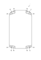
- FIG. 1 is a top view of a vehicle 1 to which a LiDAR sensor unit 10 according to this embodiment is attached. As shown in FIG. 1, the LiDAR sensor unit 10 is attached to the right front portion, the left front portion, the right rear portion, and the left rear portion of the vehicle 1.
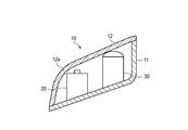
- FIG. 2 is a schematic diagram showing the LiDAR sensor unit 10 attached to the left front part of the vehicle 1.
- the LiDAR sensor unit 10 is provided together with the lamp unit 30 that illuminates the surroundings of the vehicle 1.
- the lamp unit 30 can be a headlight, a rear combination lamp, a daytime running lamp, a fog lamp, a side light, and a stop lamp.
- the LiDAR sensor unit 10 includes a housing 11 and an outer cover 12.
- a lamp unit 30 and a LiDAR sensor 20 are provided inside a space formed by the housing 11 and the outer cover 12.
- FIG. 3 is a schematic diagram of the LiDAR sensor 20.
- the LiDAR sensor 20 includes a light emitting unit 41, a light receiving unit 42, a MEMS mirror 43, and a condenser lens 44.
- the light emitted from the light emitting unit 41 is reflected by the MEMS mirror 43 and emitted to the outside of the vehicle 1 via the condenser lens 44.
- the light emitted from the light emitting unit 41 and reflected by the object (hereinafter referred to as return light) is reflected by the MEMS mirror 43 via the condenser lens 44 and enters the light receiving unit 42.
- the light emitting section 41 may emit visible light or may emit invisible light such as infrared rays and ultraviolet rays.
- the LiDAR sensor 20 emits light to the object and acquires the distance to the object from the time until the return light is detected.
- the MEMS mirror 43 is configured so that the direction in which the light reflected by the MEMS mirror 43 is emitted can be changed arbitrarily. By changing the emitting direction of the reflected light by the MEMS mirror 43, the LiDAR sensor 20 acquires a wide range of information.
- FIG. 4 is a block diagram of the LiDAR sensor 20.
- the LiDAR sensor 20 includes a light emitting unit 41, a light source control unit 45, a MEMS mirror 43, a mirror control unit 46, a light receiving unit 42, a signal processing unit 47, and a memory 48.
- the light source control unit 45 controls the operation of the light emitting unit 41.
- the mirror control unit 46 controls the operation of the MEMS mirror 43.
- the memory 48 is a rewritable recording means.
- the signal processing unit 47 processes the signal output from the light receiving unit 42 and outputs the signal to the vehicle control unit 3.
- the vehicle control unit 3 controls the behavior of the vehicle 1.
- the vehicle control unit 3 receives information from the LiDAR sensor 20 and other sensors, or signals output in response to driver's steering wheel operation, accelerator pedal operation, and brake pedal operation, in accordance with the engine, the brake device, and the steering wheel. Control the behavior of the device.
- the vehicle control unit 3 executes automatic driving of the vehicle 1. Alternatively, the vehicle control unit 3 assists the driver in driving.
- the signal processing unit 47 includes a processor and a memory. Examples of the processor include CPU, MPU, and GPU. The processor may include multiple processor cores. Examples of the memory include ROM and RAM. A program that executes the above processing may be stored in the ROM. The program may include an artificial intelligence program. An example of the artificial intelligence program is a learned neural network by deep learning. The processor is configured to specify at least a part of the program stored in the ROM, expand the program on the RAM, and execute the process in cooperation with the RAM.
- the signal processing unit 47 may be realized by a dedicated integrated circuit such as a microcontroller, FPGA, and ASIC.
- the detection principle of the LiDAR sensor 20 will be briefly described with reference to FIG.
- the signal processing unit 47 acquires information about what direction it took for the light emitted in which direction to hit the object and be reflected. Based on this, the signal processing unit 47 outputs the azimuth information and the distance to the object in the azimuth. Generally, the LiDAR sensor 20 outputs data of the azimuth angle ⁇ [°], the elevation angle ⁇ [°], and the distance d [m].
- the light source control unit 45 controls the light emitting unit 41 to emit light at predetermined time intervals.
- the mirror control unit 46 sets 100 detection points in the vertical direction and 360 detection points in the horizontal direction in a certain detection range.
- the mirror control unit 46 controls the MEMS mirror 43 so that the light entering the MEMS mirror 43 from the light emitting unit 41 is sequentially reflected toward the respective detection points.
- the light receiving unit 42 detects the return light reflected by the object at each measurement point, and outputs the detection of the return light to the signal processing unit 47. Since the MEMS mirror 43 sequentially reflects the light emitted from the light emitting unit 41 toward each measurement point, the return light sequentially detected by the light receiving unit 42 is treated as the light reflected from each measurement point. You can For example, when 36000 detection points are set, the return light detected at the first time and the return light detected at the 36001th time can be treated as light returning from the same direction. Alternatively, when it takes 0.01 seconds to emit light to all the detection points of 360,000 detection points, the light emitted 0.01 seconds after a certain time and the light emitted 0.02 seconds after a certain time. Light can be treated as light emitted in the same direction.
- the signal processing unit 47 measures, for each measurement point, the time from the time when the light emitting unit 41 emits until the return light is detected.
- the signal processing unit 47 calculates the distance to the object based on each measured time. In this way, the signal processing unit 47 outputs the distance in association with the azimuth of each detection point.
- the signal processing unit 47 outputs data such as ( ⁇ , ⁇ , d) to indicate that the distance in a certain azimuth ( ⁇ , ⁇ ) is d.
- the outer cover 12 is provided in the direction in which the light of the light emitting portion 41 of the LiDAR sensor 20 is emitted and in the direction in which the light of the light receiving portion 42 is incident.
- the outer cover 12 is often formed of a curved surface due to the design restrictions of the vehicle 1.
- the LiDAR sensor 20 is provided at a corner portion of the vehicle 1, such as the right front portion, the left front portion, the right rear portion, and the left rear portion of the vehicle 1, as shown in FIG.
- the LiDAR sensor 20 When the light of the LiDAR sensor 20 passes through the region 12a where the curvature is locally increased in this way, the light is refracted. Therefore, the LiDAR sensor 20 ends up measuring a distance in an azimuth deviating from the originally assumed azimuth. Therefore, in the LiDAR sensor 20 of this embodiment, a correction formula for correcting the influence of refraction is recorded in the memory 48 in advance before shipping the product. In the product after shipment, the output of the LiDAR sensor 20 is configured to be a value corrected by the correction formula. This processing will be described in detail.
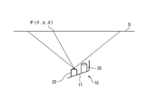
- FIG. 6 shows how the LiDAR sensor 20 is operated toward the standard screen S with the outer cover 12 not attached to the LiDAR sensor unit 10.
- the standard screen S is a flat screen having a predetermined size.
- the standard screen S and the LiDAR sensor 20 are separated by a predetermined distance and the LiDAR sensor 20 is operated.
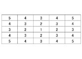
- FIG. 7 schematically shows the output of the LiDAR sensor 20 output for the region in the state shown in FIG.
- FIG. 7 shows the distances obtained by measuring the measurement range of the LiDAR sensor 20 at five measurement points in the vertical direction and at five measurement points in the horizontal direction.
- the signal processing unit 47 records the output when the standard screen S is sensed in a state where the outer cover 12 is not attached to the LiDAR sensor unit 10, in the rewritable memory 48.
- FIG. 8 shows how the LiDAR sensor 20 is operated toward the standard screen S with the outer cover 12 attached to the LiDAR sensor unit 10. Similar to FIG. 7, FIG. 9 schematically shows the output of the LiDAR sensor 20 for the region in the state shown in FIG.
- the numerical values in the 4th row and the 1st to 4th columns from the top are the same as the numerical values in the 2nd to 5th rows and the 2nd to 5th columns from the left in FIG. That is, the measurement points on the 2nd to 5th rows from the left and the 2nd to 5th columns from the top in FIG. 7 are shifted to the upper left by one column and one row by the portion 12a. Therefore, in the memory 48, the following correction formula ⁇ L (formula 2) is recorded when expressed using L (formula 1) representing the measurement point in this area.
- the correction formula in the above-described embodiment is merely an example, and the correction formula is not limited to the above.
- a correction formula suitable for the actual state of refraction may be adopted.
- the LiDAR sensor unit 10 may be provided with an inner lens inside the space formed by the housing 11 and the outer cover 12. Even before and after this inner lens is attached, the azimuth to be measured may change due to the refraction of the inner lens.
- the present invention can be applied to such a case.
- the LiDAR sensor 20 outputs when the standard screen S is sensed with the inner lens attached to the LiDAR sensor unit 10 and when the standard screen S is sensed with the inner lens not attached to the LiDAR sensor unit 10. May be configured to be compared with the output of 1 to record the correction formula in the memory 48, and to output the value obtained by applying the correction formula to the raw data as output data.
- the memory 48 uses the first difference or the first difference of the measurement data of the LiDAR sensor 20 acquired before and after mounting the outer cover 12 in the same environment. Record the first correction formula calculated from the one difference and the second difference of the measurement data of the LiDAR sensor 20 acquired before and after mounting the inner lens in the same environment or the second correction formula calculated from the second difference. You may have.
- the present invention is used to correct the difference in the LiDAR sensor output caused by the difference between the ideal mounting posture (standard state) and the actual mounting posture that occurs when the LiDAR sensor unit 10 is mounted on the vehicle 1.
- the output of the LiDAR sensor 20 obtained when the LiDAR sensor 20 is operated toward the standard screen S with the unit 10 attached to the vehicle 1 will be compared.
- the second correction formula derived from these comparisons is recorded in the memory 48.
- a second correction formula that corrects the deviation of the actual mounting posture from the standard state is also applied to the raw data of the LiDAR sensor 20. It may be configured to output to the control unit 3.
- the processing unit acquires the measurement data of the LiDAR sensor 20 obtained with the LiDAR sensor unit 10 attached to the vehicle 1 in the same environment, and the LiDAR sensor obtained with the LiDAR sensor unit 10 attached to the vehicle in the standard state. Based on the difference from the measurement data of 20, the raw data acquired from the LiDAR sensor unit 10 attached to the vehicle 1 may be corrected by a correction formula according to the difference, and the correction data may be output.
- the time output is recorded in the rewritable memory 48.
- the outer cover 12 may be scratched or damaged by flying stones. Refraction may occur even at such a scratched portion, or light may be scattered so that the distance cannot be measured well. Even if the flaw is a small inconspicuous flaw, if the flaw is located on the extension line of the measurement direction, the LiDAR sensor 20 is affected by the flaw. However, it is not realistic to replace the outer cover 12 because it causes a small scratch.
- the information recorded in the memory 48 can be periodically updated.
- the inspection using the standard screen S described above is performed.
- the contents of the memory 48 can be rewritten periodically. Accordingly, even if the light is refracted due to the scratch, it is possible to avoid the defect caused by the scratch by setting the correction formula appropriately.
- the contents of the memory 48 can be updated to a correction formula according to the shape of the outer cover 12 after replacement.
- the LiDAR sensor units 10 provided on the right front portion, the left front portion, the right rear portion, and the left rear portion of the vehicle 1 have been described, but the present invention is applicable to all LiDAR sensor units regardless of the mounting location of the vehicle 1. It can be applied to the sensor unit 10.
- the present invention is not limited to this.
- the LiDAR sensor 20 may be provided independently of the lamp unit 30.
- the LiDAR sensor 20 may be provided inside the outer cover 12 and the housing 11, which are common to other sensors such as a camera and a millimeter wave radar.
- the electronic circuit that realizes the function of correcting the output of the LiDAR sensor 20 described with reference to FIGS. 6 to 10 realizes the function of detecting the incidence of light on the light receiving unit and calculating the distance to the object. It may be provided separately from the electronic circuit. That is, the electronic circuit built in the LiDAR sensor 20 realizes the function of detecting the incidence of light on the light receiving section and calculating the distance of the object, and the electronic circuit is provided in the middle of the communication path between the LiDAR sensor 20 and the vehicle control section 3. An electronic circuit that implements the output correction function by the correction formula may be provided.
- Vehicle security system 102 a vehicle security system using a LiDAR sensor is provided.
- FIG. 10 is a top view of a vehicle 101 to which the vehicle security system 102 according to the present embodiment is attached.
- the vehicle security system 102 includes a plurality of LiDAR sensor units 110. As shown in FIG. 10, the LiDAR sensor units 110 are attached to the right front portion, the left front portion, the right rear portion, and the left rear portion of the vehicle 101.
- the structure of the LiDAR sensor unit 110 is the same as that of the LiDAR sensor unit 10 described in FIG.
- the structure of the lamp unit 130 is also the same as that of the lamp unit 30 described in FIG. Therefore, the description of the LiDAR sensor unit 110 and the lamp unit 130 is omitted.
- the structure of the LiDAR sensor 120 is also similar to that of the LiDAR sensor 20 described with reference to FIG. 3, and thus the description thereof will be omitted.
- FIG. 11 is a block diagram of the vehicle security system 102.
- the vehicle security system 102 includes a LiDAR sensor 120, a lamp unit 130, an image forming unit 151, an image comparing unit 152, and a lamp control unit 153 (control unit).
- the LiDAR sensor 120 includes a light emitting unit 141, a light source control unit 145, a MEMS mirror 143, a mirror control unit 146, a light receiving unit 142, and a signal processing unit 147.
- the light source control unit 145 controls the operation of the light emitting unit 141.
- the mirror control unit 146 controls the operation of the MEMS mirror 143.
- the lamp control unit 153 controls turning on/off of the lamp unit 130.
- the signal processing unit 147 processes the signal output from the light receiving unit 142 and outputs the signal to the vehicle control unit 103.
- the vehicle control unit 103 controls the behavior of the vehicle 101.
- the operation of the vehicle control unit 103 is the same as the operation of the vehicle control unit 3 described above, and thus the description thereof is omitted.
- the details of the signal processing unit 147 are the same as those of the signal processing unit 47 described above, and thus the description thereof will be omitted. Further, the detection principle of the LiDAR sensor has already been described with reference to FIG.
- FIG. 12 is a flowchart of processing executed by the vehicle security system 102.
- FIG. 13 shows a state around the parked vehicle 101 at time t ⁇ 1, which is a predetermined time before a certain time t. At time t-1, the vehicle 101 is parked in the parking lot.
- FIG. 14 is an image I[t ⁇ 1] formed by the image forming unit 151 based on the measurement data acquired by the LiDAR sensor 120 in the state of FIG. 13.
- the LiDAR sensor 120 measures distances at all measurement points.
- An image I[t-1] is formed (step S01).
- FIG. 15 shows a state around the parked vehicle 101 at time t.
- the pedestrian A approaches the parked vehicle 101 from the upper right in FIG.
- FIG. 16 is an image I[t] formed by the image forming unit 151 based on the measurement data acquired by the LiDAR sensor 120 in the state of FIG.
- the LiDAR sensor 120 measures distances at all measurement points.
- the image comparison unit 152 compares the image I[t-1] acquired at time t-1 with the image I[t] acquired at time t.
- the image comparison unit 152 determines whether or not the images I[t-1] and I[t] of the two have a difference of a predetermined value or more (step S03). For example, the image comparison unit 152 determines that a difference of a predetermined value or more occurs when the number of pixels having a difference between the images I[t ⁇ 1] and I[t] of the two is a predetermined value or more.
- the image comparing unit 152 sets the images I[t-1] and I[t] of the both to be equal to or more than a predetermined value. It is determined that there is a difference.
- the ratio of the number of pixels having a difference with respect to all the pixels set as the threshold value may be configured so that the user can change it stepwise, such as 5% or 10%.
- step S03 If there is no difference between the images I[t-1] and I[t] of the predetermined values (step S03: No), the vehicle security system 102 ends the process.
- the image comparison unit 152 determines which direction the difference is from the host vehicle 101. Identify what is happening to the. Further, the image comparison unit 152 outputs the specified azimuth to the lamp control unit 153 (step S04). In the illustrated example, the specified azimuth is only the position direction on the upper right of the host vehicle 101. However, if the difference occurs in a plurality of azimuths, the plural azimuths are specified and output to the lamp control unit 153. Good.
- the image comparison unit 152 compares the images I[t-1] and I[t] of both images and identifies that there is a difference of a predetermined value or more in the upper right area of the host vehicle 101. To do.
- the image comparison unit 152 outputs to the lamp control unit 153 that a difference of a predetermined value or more has occurred in the upper right area.
- the lamp control unit 153 controls the lamp unit 130 based on the input from the image comparison unit 152 to irradiate the light in a specific direction (step S05). In the illustrated example, the lamp control unit 153 turns on the lamp unit 130 provided in the front right part of the vehicle 101.
- the image comparison unit 152 divides the image I[t] acquired at the time t into 12 regions in the circumferential direction around the host vehicle 101.
- the image comparison unit 152 may be configured to specify to which region the pixel having the difference belongs and output the belonging region to the lamp control unit 153.
- the lamp control unit 153 may be configured to turn on the lamp unit 130 that can emit light toward the input area.
- the vehicle security system 102 using the LiDAR sensor 120 is provided.
- the LiDAR sensor 120 is suitable for a crime prevention system because it can acquire the shape of a target object with high accuracy. Further, the LiDAR sensor 120 is often mounted on the vehicle 101 capable of autonomous driving. The LiDAR sensor 120 mounted on the vehicle 101 capable of autonomous driving is in operation while traveling, but is not used during parking.
- the vehicle security system 102 using the LiDAR sensor 120 of the present embodiment can use the LiDAR sensor 120 that is not used during parking, and does not need to use a separate sensor only for the vehicle security system 102. It is rational.
- the vehicle security system 102 may be configured to be able to distinguish the owner of the vehicle 101 and a registered person (called a user) from unregistered persons.
- the vehicle security system 102 may include a user information recording unit 154 (see FIG. 11).
- the user information recording unit 154 records a specific shape associated with the user.
- the image comparison unit 152 determines that there is a difference between the image I[t-1] at time t-1 and the image I[t] at time t, and then determines that there is a difference in the image I[t] at time t. It is determined whether or not the marked portion matches the shape recorded in the user information recording unit 154. If they match, the lamp control unit 153 turns on the lamp unit 130 by a method different from the case where the two do not match.
- the lamp unit 130 is always turned on in the corresponding direction, and the different portion is the user information recording unit 154. If the shape does not match the shape recorded in, the lamp unit 130 may be configured to blink toward the corresponding area.
- the user information recording unit 154 can record the shape of the user's face, the shape of the key chain owned by the user, and the like.
- the lamp control unit 153 makes the lighting mode of the lamp unit 130 different between the case where the shapes match and the case where the shapes do not match, differentiating lighting, blinking, and blinking of the lamp unit 130, different lighting colors, and brightness. Including differentiating. Further, when the lamp unit 130 has a plurality of light sources, differentiating the lighting mode of the lamp unit 130 includes differentiating the number and shape of the light sources to be lighted.
- the light source control unit 145 of the vehicle security system 102 operates the LiDAR sensor 120 during parking with a resolution lower than the resolution of sensing performed during traveling, or based on a sensing cycle performed during traveling. May be configured to operate in a long cycle.
- a resolution lower than the resolution (the number of measurement points) required during traveling is sufficient.
- the cycle is longer than the cycle (scan cycle) required during traveling.
- the image forming unit 151, the image comparison unit 152, and the lamp control unit 153 may be configured integrally with the signal processing unit 147 or may be configured separately.
- the image forming unit 151, the image comparing unit 152, and the lamp control unit 153 may be provided in the middle of the communication path between the signal processing unit 147 and the vehicle control unit 103.
- the lamp control unit 153 when the image comparison unit 152 has a difference between the image at time t ⁇ 1 and the image at time t, the lamp control unit 153 outputs the different orientations, and the lamp control unit 153.
- the LiDAR sensor unit 110 is provided with a directional speaker
- the sound source control unit determines the different orientation.
- the sound source control unit may output the sound and emit the sound toward the direction corresponding to the directional speaker.
- the LiDAR sensor 120 provided on the right front portion, the left front portion, the right rear portion, and the left rear portion of the vehicle 101 has been described, but the present invention is applicable to all LiDAR sensors regardless of the mounting location of the vehicle 101. Applicable to 120.
- the LiDAR sensor 120 is provided inside the outer cover 112 and the housing 111 that are common with the lamp unit 130 , but the present invention is not limited to this.
- the LiDAR sensor 120 may be provided independently of the lamp unit 130. Further, the LiDAR sensor 120 may be provided inside the outer cover 112 and the housing 111, which are common to other sensors such as a camera and a millimeter wave radar.
- a LiDAR sensor unit that is less likely to be affected by the lens element on measurement data is provided.
Landscapes
- Physics & Mathematics (AREA)
- Engineering & Computer Science (AREA)
- General Physics & Mathematics (AREA)
- Radar, Positioning & Navigation (AREA)
- Remote Sensing (AREA)
- Computer Networks & Wireless Communication (AREA)
- Electromagnetism (AREA)
- Optical Radar Systems And Details Thereof (AREA)
- Alarm Systems (AREA)
Abstract
レンズ要素が設けられていても、測定データに該レンズ要素の影響が及びにくいLiDARセンサユニットを提供する。LiDARセンサユニット(10)は、LiDARセンサ(20)と、レンズ要素(12)と、LiDARセンサ(20)が測定した測定データを出力する処理部(47)を有する。処理部(47)は、同じ環境においてレンズ要素(12)をLiDARセンサユニット(10)に取り付ける前後で取得したLiDARセンサ(20)の測定データの差分に基づいて、レンズ要素(12)を取り付けたLiDARセンサ(20)から取得した生データLrawを差分に応じた補正式ΔLにより補正した補正データLoutを出力するように構成されている。
Description
本発明は、LiDARセンサユニットおよび車両用防犯システムに関する。
対象物との距離を測定する車両用のLiDARセンサが知られている。
このようなLiDARを車両に搭載する際には、LiDARセンサを保護するために透明なカバーが設けられる。あるいは、光を発する発光部や受光部の前に、レンズ要素を設けて集光率が高められたりしている。このようなカバーやインナレンズなどのレンズ要素を設けると、発光部から発せられる光が屈曲し、レンズ要素を設けない状態と比べて、測定データに変化が生じてしまう。
本発明は、レンズ要素が設けられていても、測定データに該レンズ要素の影響が及びにくいLiDARセンサユニットを提供する。
また本発明は、LiDARセンサを用いた車両用防犯システムを提供する。
本発明は、レンズ要素が設けられていても、測定データに該レンズ要素の影響が及びにくいLiDARセンサユニットを提供する。
また本発明は、LiDARセンサを用いた車両用防犯システムを提供する。
本発明の一側面に係るLiDARセンサユニットは、
LiDARセンサと、
前記LiDARセンサから出射される光の光路上に設けられたレンズ要素と、
前記LiDARセンサが測定した測定データを出力する処理部を有する、LiDARセンサユニットであって、
前記処理部は、同じ環境において前記レンズ要素を前記LiDARセンサユニットに取り付ける前後で取得した前記LiDARセンサの前記測定データの差分に基づいて、前記レンズ要素を取り付けた前記LiDARセンサから取得した生データを前記差分に応じた補正式により補正した補正データを出力するように構成されている。
LiDARセンサと、
前記LiDARセンサから出射される光の光路上に設けられたレンズ要素と、
前記LiDARセンサが測定した測定データを出力する処理部を有する、LiDARセンサユニットであって、
前記処理部は、同じ環境において前記レンズ要素を前記LiDARセンサユニットに取り付ける前後で取得した前記LiDARセンサの前記測定データの差分に基づいて、前記レンズ要素を取り付けた前記LiDARセンサから取得した生データを前記差分に応じた補正式により補正した補正データを出力するように構成されている。
本発明の一側面に係る車両用防犯システムは、
車両に搭載され、車両の周囲の情報を取得するLiDARセンサと、
前記LiDARセンサの出力に基づいて画像を生成する画像形成部と、
任意の2時点で取得した前記LiDARセンサの出力に基づいて生成された2つの画像を比較する画像比較部と、
特定の方位に向けて光または音を発する光源または音源と、
前記光源または音源を制御する制御部を有し、
前記制御部は、車両の駐車中に、前記画像比較部の出力に基づき、前記2つの画像の差分が閾値より大きい方位に向けて、前記光源または前記音源から光または音を発信させる。
車両に搭載され、車両の周囲の情報を取得するLiDARセンサと、
前記LiDARセンサの出力に基づいて画像を生成する画像形成部と、
任意の2時点で取得した前記LiDARセンサの出力に基づいて生成された2つの画像を比較する画像比較部と、
特定の方位に向けて光または音を発する光源または音源と、
前記光源または音源を制御する制御部を有し、
前記制御部は、車両の駐車中に、前記画像比較部の出力に基づき、前記2つの画像の差分が閾値より大きい方位に向けて、前記光源または前記音源から光または音を発信させる。
本発明によれば、レンズ要素が設けられていても、測定データに該レンズ要素の影響が及びにくいLiDARセンサユニットが提供される。また、本発明によれば車両用防犯システムが提供される。
添付の図面を参照しつつ、実施形態の例について以下詳細に説明する。以下の説明に用いる各図面では、各部材を認識可能な大きさとするために縮尺を適宜変更している。
<LiDARセンサユニット>
図1は、本実施形態に係るLiDARセンサユニット10が取り付けられた車両1の上面図である。図1に示したように、車両1の右前部、左前部、右後部、左後部にLiDARセンサユニット10が取り付けられている。
図1は、本実施形態に係るLiDARセンサユニット10が取り付けられた車両1の上面図である。図1に示したように、車両1の右前部、左前部、右後部、左後部にLiDARセンサユニット10が取り付けられている。
図2は、車両1の左前部に取り付けられたLiDARセンサユニット10を示す模式図である。本実施形態において、LiDARセンサユニット10は、車両1の周囲を照らすランプユニット30とともに設けられている。ランプユニット30は、前照灯、リアコンビネーションランプ、デイタイムランニングランプ、フォグランプ、車幅灯、ストップランプとすることができる。LiDARセンサユニット10は、ハウジング11と、アウタカバー12とを備えている。ハウジング11とアウタカバー12で形成される空間の内部に、ランプユニット30とLiDARセンサ20が設けられている。
図3は、LiDARセンサ20の模式図である。図3に示すように、LiDARセンサ20は、発光部41と、受光部42と、MEMSミラー43と、集光レンズ44とを備えている。
発光部41から出射した光は、MEMSミラー43で反射され、集光レンズ44を介して車両1の外部に出射される。発光部41から出射して対象物に反射された光(以降、戻り光と呼ぶ)は、集光レンズ44を介してMEMSミラー43で反射され、受光部42に入射する。発光部41は、可視光を出射してもよいし、赤外線や紫外線などの非可視光を出射してもよい。LiDARセンサ20は、対象物へ光を発し、戻り光を検出するまでの時間から対象物との距離を取得する。MEMSミラー43は、MEMSミラー43で反射される光が出射する方位を任意に変更可能に構成されている。MEMSミラー43により反射光の出射方向を変更することにより、LiDARセンサ20は広い範囲の情報を取得する。
発光部41から出射した光は、MEMSミラー43で反射され、集光レンズ44を介して車両1の外部に出射される。発光部41から出射して対象物に反射された光(以降、戻り光と呼ぶ)は、集光レンズ44を介してMEMSミラー43で反射され、受光部42に入射する。発光部41は、可視光を出射してもよいし、赤外線や紫外線などの非可視光を出射してもよい。LiDARセンサ20は、対象物へ光を発し、戻り光を検出するまでの時間から対象物との距離を取得する。MEMSミラー43は、MEMSミラー43で反射される光が出射する方位を任意に変更可能に構成されている。MEMSミラー43により反射光の出射方向を変更することにより、LiDARセンサ20は広い範囲の情報を取得する。
図4は、LiDARセンサ20のブロック図である。図4に示すように、LiDARセンサ20は、発光部41と、光源制御部45と、MEMSミラー43と、ミラー制御部46と、受光部42と、信号処理部47と、メモリ48を備えている。光源制御部45は、発光部41の動作を制御する。ミラー制御部46は、MEMSミラー43の動作を制御する。メモリ48は、書き換え可能な記録手段である。信号処理部47は、受光部42から出力される信号を処理し、車両制御部3へ出力する。車両制御部3は、車両1の挙動を制御する。
車両制御部3はLiDARセンサ20や他のセンサからの出力、あるいはドライバーのステアリングホイールの操作、アクセルペダルの操作、ブレーキペダルの操作に応じて出力される信号に応じて、エンジン、ブレーキ装置、ステアリング装置の挙動を制御する。車両制御部3は、車両1の自動運転を実行する。あるいは、車両制御部3は、ドライバーの運転を支援する。
信号処理部47は、プロセッサとメモリを備えている。プロセッサの例としては、CPU、MPU、GPUが挙げられる。プロセッサは、複数のプロセッサコアを含みうる。メモリの例としては、ROMやRAMが挙げられる。ROMには、上記の処理を実行するプログラムが記憶されうる。当該プログラムは、人工知能プログラムを含みうる。人工知能プログラムの例としては、ディープラーニングによる学習済みニューラルネットワークが挙げられる。プロセッサは、ROMに記憶されたプログラムの少なくとも一部を指定してRAM上に展開し、RAMと協働して処理を実行するように構成されている。信号処理部47は、マイクロコントローラ、FPGA、ASICなどの専用集積回路によって実現されてもよい。
図5を用いて、LiDARセンサ20の検出原理を簡単に説明する。
信号処理部47は、どこの方位に発した光が対象物に当たって反射してくるまでに、どの程度の時間がかかったか、という情報を取得する。これを基に信号処理部47は、方位情報と、該方位における物体までの距離を出力する。一般的に、LiDARセンサ20は、方位角θ[°]と、仰角φ[°]と、距離d[m]のデータを出力する。
信号処理部47は、どこの方位に発した光が対象物に当たって反射してくるまでに、どの程度の時間がかかったか、という情報を取得する。これを基に信号処理部47は、方位情報と、該方位における物体までの距離を出力する。一般的に、LiDARセンサ20は、方位角θ[°]と、仰角φ[°]と、距離d[m]のデータを出力する。
例えば、光源制御部45は、所定時間間隔で光を発するように発光部41を制御する。ミラー制御部46は、ある検出範囲に、縦方向に100点、横方向に360点の検出点を設定する。ミラー制御部46は、発光部41からMEMSミラー43に入射する光を順に、各々の検出点に向けて反射させるようにMEMSミラー43を制御する。
受光部42は、各々の測定点について、対象物に当たって反射してきた戻り光を検出し、戻り光を検出したことを信号処理部47に出力する。MEMSミラー43は、発光部41から発した光を順に各々の測定点に向けて反射させているので、受光部42が順に検出した戻り光は、各々の測定点から反射された光として扱うことができる。例えば、36000点の検出点が設定されている場合、1回目に検出した戻り光と、36001回目に検出した戻り光は、同じ方位から戻ってきた光だと扱うことができる。あるいは、360000点の検出点の全ての検出点に向けて光を発するまでに0.01秒かかる場合、ある時刻から0.01秒後に発した光と、ある時刻から0.02秒後に発した光は、同じ方位に発した光として扱うことができる。
信号処理部47は、各々の測定点について、発光部41が発した時間から戻り光を検出するまでの時間を測定する。信号処理部47は、各々の測定した時間に基づいて、対象物との距離を算出する。このようにして信号処理部47は、各々の検出点の方位と関連付けて、距離を出力する。信号処理部47は、ある方位(θ,φ)の距離がdであることを示すために、(θ,φ,d)といったデータを出力する。
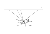
ところで、図2に示したように、LiDARセンサ20の発光部41の光を出射する方向、受光部42の光が入射する方向には、アウタカバー12が設けられている。アウタカバー12は、車両1のデザインの制約上、曲面で構成されることが多い。特に、図1に示したように、車両1の右前部、左前部、右後部、左後部といった、車両1のコーナー部分にLiDARセンサ20が設けられる場合には、図2に示したようにアウタカバー12の曲面の曲率が局所的に大きくなる部位12aがある。
このように曲率が局所的に大きくなっている部位12aを、LiDARセンサ20の光が通過すると、光が屈折してしまう。このため、LiDARセンサ20は、本来想定していた方位から外れた方位の距離を測定してしまうことになってしまう。このため、本実施形態のLiDARセンサ20においては、製品の出荷前に予め屈折の影響を補正する補正式がメモリ48に記録されている。出荷後の製品においては、LiDARセンサ20の出力は補正式で補正された値が出力されるように構成されている。この処理について詳述する。
図6は、アウタカバー12をLiDARセンサユニット10に取り付けていない状態で標準スクリーンSに向けてLiDARセンサ20を作動させる様子を示している。標準スクリーンSは、所定の大きさの平面状のスクリーンである。図6では、この標準スクリーンSとLiDARセンサ20とを所定距離離間させて、LiDARセンサ20を作動させた。
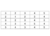
図7は、図6に示した状態である領域について出力されるLiDARセンサ20の出力を模式的に表したものである。図7は、LiDARセンサ20がある測定範囲を縦方向に5個の測定点、横方向に5個の測定点で測定して得られた距離を示したものである。説明の便宜のために、図7においては、中心の測定点の距離が1であり、四隅の測定点の距離が5であったとしている。信号処理部47は、アウタカバー12をLiDARセンサユニット10に取り付けていない状態で標準スクリーンSをセンシングした時の出力を、書き換え可能なメモリ48に記録する。
図8は、アウタカバー12をLiDARセンサユニット10に取り付けた状態で標準スクリーンSに向けてLiDARセンサ20を作動させる様子を示している。図9は、図7と同様に、図8に示した状態である領域について出力されるLiDARセンサ20の出力を模式的に表したものである。
アウタカバー12を取り付けた状態でLiDARセンサ20を作動させると、図8に示したように、アウタカバー12の局所的に曲率が大きい部位12aで光が屈折してしまう。図8においては、部位12aで屈折の影響を受けなかった場合に光が進む光路を破線で、部位12aで屈折の影響を受けた場合に光が進む光路を実線で示している。本実施形態において、図7と図9を比較すると、図で表される領域においては、左から5行目、および、上から5列目の数値に変化はないものの、図9の左から1~4行目かつ上から1~4列目の数値は、図7の左から2~5行目かつ上から2~5列目の数値と同一になっている。つまり、図7の左から2~5行目かつ上から2~5列目の測定点は、部位12aによって1列および1行分、左上にずれてしまった。そこで、メモリ48には、この領域の測定点を表すL(式1)を使って表すと、以下の補正式ΔL(式2)が記録されている。
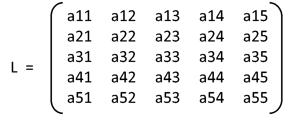
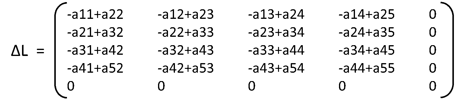
そこで信号処理部47は、未加工の生データをLrawで表すと、車両制御部3へ出力データLoutをLout=Lraw+ΔLとして算出する。つまり本実施形態のLiDARセンサユニット10において、LiDARセンサ20は生データLrawを測定する。しかしながら、LiDARセンサ20は、この生データLrawをそのまま車両制御部3へ出力するのではなく、メモリ48に記録された補正式ΔLを生データLrawに適用したデータLoutを車両制御部3へ出力する。これにより、LiDARセンサ20は、アウタカバー12をLiDARセンサユニット10に取り付けない状態で出力されるはずだった値を車両制御部3へ出力することができる。これにより、アウタカバー12によってLiDARセンサ20から出射される光が屈折することによる測定誤差を含まない測定データをLiDARセンサ20から取得することができる。
なお、上述した実施形態における補正式は単なる一例であり、補正式は上述のものに限られない。実際の屈折の様子に応じて適した補正式を採用すればよい。
なお、上述した実施形態における補正式は単なる一例であり、補正式は上述のものに限られない。実際の屈折の様子に応じて適した補正式を採用すればよい。
上述した実施形態においては、アウタカバー12を取り付ける前と取り付けた後の測定点を取り扱う例を説明したが、本発明はこれに限られない。LiDARセンサユニット10には、ハウジング11とアウタカバー12で形成される空間の内部にインナレンズが設けられる場合がある。このインナレンズを取り付ける前と取り付ける後においても、インナレンズの屈折により測定しようとする方位が変化してしまう場合がある。このような場合にも本発明を適用することができる。
すなわち、LiDARセンサ20は、インナレンズをLiDARセンサユニット10に取り付けた状態で標準スクリーンSをセンシングした時の出力と、インナレンズをLiDARセンサユニット10に取り付けていない状態で標準スクリーンSをセンシングした時の出力とを比較し、補正式をメモリ48に記録し、生データに補正式を適用して得られる値を出力データとして出力するように構成されていてもよい。
LiDARセンサユニット10が、アウタカバー12とインナレンズの両方を搭載している場合には、メモリ48は、同じ環境においてアウタカバー12を搭載する前後で取得したLiDARセンサ20の測定データの第一差分または第一差分から算出される第一補正式と、同じ環境においてインナレンズを搭載する前後で取得したLiDARセンサ20の測定データの第二差分または第二差分から算出される第二補正式と、を記録していてもよい。
また、本発明は、LiDARセンサユニット10を車両1に搭載する際に生じる、理想的な取付姿勢(標準状態)と実際の取付姿勢の差に起因するLiDARセンサ出力の差を補正するために用いることもできる。すなわち、標準状態でLiDARセンサユニット10を車両1に取り付け、標準スクリーンSに向けてLiDARセンサ20を動作させたときに得られるであろうLiDARセンサ20の出力(設計値)と、実際にLiDARセンサユニット10を車両1に取り付けた状態で標準スクリーンSに向けてLiDARセンサ20を動作させた時に得たLiDARセンサ20の出力を比較する。これらの比較から導出される第二補正式がメモリ48に記録されている。LiDARセンサユニットは、アウタカバー12の屈折の影響を排除する補正式に加えて、実際の取り付け姿勢の標準状態からのずれを補正する第二補正式も、LiDARセンサ20の生データに適用し、車両制御部3に出力するように構成してもよい。
すなわち、処理部は、同じ環境においてLiDARセンサユニット10を車両1に取り付けた状態で取得したLiDARセンサ20の測定データと、LiDARセンサユニット10を標準状態で車両に取り付けた状態で取得されるLiDARセンサ20の測定データとの差分に基づいて、車両1に取り付けられたLiDARセンサユニット10から取得した生データを差分に応じた補正式により補正した補正データを出力するように構成されていてもよい。
また、本実施形態においては、アウタカバー12をLiDARセンサユニット10に取り付けていない状態で標準スクリーンSをセンシングした時の出力と、アウタカバー12をLiDARセンサユニット10に取り付けた状態で標準スクリーンSをセンシングした時の出力とが、書き換え可能なメモリ48に記録されている。
アウタカバー12は、飛び石などによって傷が付いたり破損したりすることがある。このように傷がついた個所でも屈折が生じたり、光が散乱してしまって上手く距離を測定できなくなってしまうことがある。小さな目立たない傷であっても、該傷が測定方位の延長線上に位置してしまう場合には、LiDARセンサ20は該傷の影響を受けてしまう。しかしながら、小さな傷が付いてしまうためにアウタカバー12を交換することは現実的ではない。
そこで本実施形態においては、定期的にメモリ48に記録される情報を更新することができる。例えば、車両の定期点検などにおいて、上述した標準スクリーンSを使った検査を行う。該検査において、アウタカバー12をLiDARセンサユニット10に取り付けていない状態で標準スクリーンSをセンシングした時の出力と、アウタカバー12をLiDARセンサユニット10に取り付けた状態で標準スクリーンSをセンシングした時の出力とを取得し、メモリ48の内容を定期的に書き換えることができる。これにより、傷に起因して光が屈折してしまう場合でも、補正式を適式に設定することにより、傷に起因する不具合を回避することができる。
また、アウタカバー12の交換時にも、交換後のアウタカバー12の形状に応じた補正式にメモリ48の内容を更新することができる。
また、上述した実施形態においては、車両1の右前部、左前部、右後部、左後部に設けられるLiDARセンサユニット10について説明したが、本発明は、車両1の搭載場所を問わず全てのLiDARセンサユニット10について適用できる。
さらに、上述した実施形態においては、LiDARセンサ20がランプユニット30とともに共通のアウタカバー12とハウジング11の内部に設けられる例を説明したが、本発明はこれに限られない。LiDARセンサ20がランプユニット30とは独立して設けられていてもよい。あるいは、LiDARセンサ20がカメラやミリ波レーダなどの他のセンサと共通のアウタカバー12とハウジング11の内部に設けられていてもよい。
なお、図6から図10を用いて説明したLiDARセンサ20の出力を補正する機能を実現する電子回路は、受光部への光の入射を検出して対象物の距離を算出する機能を実現する電子回路とは別に設けられていてもよい。すなわち、LiDARセンサ20に内蔵される電子回路が受光部への光の入射を検出して対象物の距離を算出する機能を実現し、LiDARセンサ20と車両制御部3との通信経路の途中に、補正式による出力の補正機能を実現する電子回路が設けられていてもよい。
<車両用防犯システム>
次に、本発明に係る車両用防犯システム102について説明する。本発明によれば、LiDARセンサを使った車両用防犯システムが提供される。
次に、本発明に係る車両用防犯システム102について説明する。本発明によれば、LiDARセンサを使った車両用防犯システムが提供される。
図10は、本実施形態に係る車両用防犯システム102が取り付けられた車両101の上面図である。車両用防犯システム102は、複数のLiDARセンサユニット110を有している。図10に示したように、車両101の右前部、左前部、右後部、左後部にLiDARセンサユニット110が取り付けられている。
LiDARセンサユニット110の構造は、図2で説明したLiDARセンサユニット10と同様である。また、ランプユニット130の構造についても図2で説明したランプユニット30と同様である。このため、LiDARセンサユニット110およびランプユニット130の説明は省略する。LiDARセンサ120の構造も、図3で説明したLiDARセンサ20と同様であるため、その説明は省略する。
図11は、車両用防犯システム102のブロック図である。図11に示すように車両用防犯システム102は、LiDARセンサ120と、ランプユニット130と、画像形成部151と、画像比較部152と、ランプ制御部153(制御部)を備えている。図11に示すように、LiDARセンサ120は、発光部141と、光源制御部145と、MEMSミラー143と、ミラー制御部146と、受光部142と、信号処理部147を備えている。光源制御部145は、発光部141の動作を制御する。ミラー制御部146は、MEMSミラー143の動作を制御する。ランプ制御部153は、ランプユニット130の点消灯を制御する。信号処理部147は、受光部142から出力される信号を処理し、車両制御部103へ出力する。車両制御部103は、車両101の挙動を制御する。
車両制御部103の動作については、上述した車両制御部3の動作と同様であるため、その説明を省略する。
信号処理部147の詳細についても、上述した信号処理部47と同様であるため、その説明を省略する。またLiDARセンサの検出原理についても、図5で既に説明しているため、その説明を省略する。
信号処理部147の詳細についても、上述した信号処理部47と同様であるため、その説明を省略する。またLiDARセンサの検出原理についても、図5で既に説明しているため、その説明を省略する。
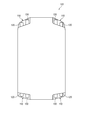
図12は、車両用防犯システム102が実行する処理のフローチャートである。図13は、ある時刻tから所定時間前の時刻t-1における駐車している車両101の周囲の様子を示す。時刻t-1においては、車両101は駐車場に駐車している。図14は、図13の状態においてLiDARセンサ120が取得した測定データに基づいて画像形成部151が形成した画像I[t-1]である。
時刻t-1において、LiDARセンサ120は全ての測定点について距離を測定している。画像形成部151は、時刻t-1における測定データP[t-1]=(θ[t-1],φ[t-1],d[t-1])を取得し、図14に示した画像I[t-1]を形成する(ステップS01)。
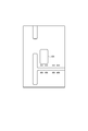
図15は、時刻tにおける駐車している車両101の周囲の様子を示す。時刻tにおいては、歩行者Aが、駐車している車両101に図15における右上から接近している。図16は、図15の状態においてLiDARセンサ120が取得した測定データに基づいて画像形成部151が形成した画像I[t]である。
時刻tにおいて、LiDARセンサ120は全ての測定点について距離を測定している。画像形成部151は、時刻tにおける測定データP[t]=(θ[t],φ[t],d[t])を取得し、図16に示した画像I[t]を形成する(ステップS02)。
画像比較部152は、時刻t-1で取得した画像I[t-1]と、時刻tで取得した画像I[t]とを比較する。画像比較部152は、両者の画像I[t-1],I[t]に所定値以上の差異が生じているか否かを判定する(ステップS03)。例えば画像比較部152は、両者の画像I[t-1],I[t]に差異がある画素数が所定値以上であるときに、所定値以上の差異が生じていると判定する。例えば画像比較部152が、画像を構成する全画素数に対して、差異がある画素数が3%以上であるときに、両者の画像I[t-1],I[t]に所定値以上の差異が生じていると判定する。閾値に設定する全画素に対する差異がある画素数の割合は、5%、10%など、ユーザが段階的に変更可能に構成されていてもよい。
両者の画像I[t-1],I[t]に所定値以上の差異が生じていない場合には(ステップS03:No)、車両用防犯システム102は処理を終了する。
両者の画像I[t-1],I[t]に所定値以上の差異が生じている場合には(ステップS03:Yes)、画像比較部152は、差異が自車両101から見てどの方位に生じているかを特定する。さらに、画像比較部152は、特定した方位をランプ制御部153へ出力する(ステップS04)。なお図示の例では、特定する方位は自車両101の右上の位置方向のみであるが、差異が複数の方位で生じている場合には、複数の方位を特定しランプ制御部153へ出力してもよい。
図示の例では、画像比較部152は、両者の画像I[t-1],I[t]を比較して、自車両101の右上の領域に所定値以上の差異が生じていることを特定する。画像比較部152は、所定値以上の差異が右上の領域に生じていることをランプ制御部153に出力する。
ランプ制御部153は、画像比較部152からの入力に基づいて、特定の方位に向けて光を照射するようにランプユニット130を制御する(ステップS05)。図示の例では、ランプ制御部153は、車両101の右前部に設けられたランプユニット130を点灯させる。
このとき、画像比較部152は、時刻tで取得した画像I[t]を自車両101を中心に周方向に12個の領域に区分けしている。画像比較部152は、方位を特定する代わりに、差異の生じている画素がどの領域に属しているかを特定し、属している領域をランプ制御部153に出力するように構成してもよい。この場合、ランプ制御部153は、入力されてきた領域に向けて光を出射可能なランプユニット130を点灯させるように構成してもよい。
本実施形態によれば、LiDARセンサ120を使った車両用防犯システム102が提供される。LiDARセンサ120は、高精度に対象物の形状を取得することができるため、防犯システムに適している。また、LiDARセンサ120は自動運転可能な車両101に搭載されることが多い。自動運転可能な車両101に搭載されたLiDARセンサ120は走行中は稼働しているものの、駐車中は使われていない。本実施形態のLiDARセンサ120を使った車両用防犯システム102は、駐車中に使用されていないLiDARセンサ120を用いることができ、車両用防犯システム102のためだけに別途センサを用いる必要が無く、合理的である。
なお、本実施形態において、車両用防犯システム102は、車両101のオーナーや登録された人物(ユーザと呼ぶ)を、登録していない人物と識別可能に構成されていてもよい。車両用防犯システム102はユーザ情報記録部154(図11参照)を有していてもよい。ユーザ情報記録部154は、ユーザと関連づけられた特定の形状を記録している。画像比較部152は、時刻t-1の画像I[t-1]と時刻tの画像I[t]とに相違があると判定した後に、時刻tの画像I[t]中の差異のあった部分が、ユーザ情報記録部154に記録されている形状と一致するか否かを判定する。両者が一致していれば、ランプ制御部153は、両者が一致していない場合とは異なる方法でランプユニット130を点灯させる。
例えば、差異のあった部分がユーザ情報記録部154に記録されている形状と一致していれば該当する方位に向けてランプユニット130を常時点灯させ、差異のあった部分がユーザ情報記録部154に記録されている形状と一致していなければ該当する領域に向けてランプユニット130を点滅させるように構成してもよい。例えばユーザ情報記録部154は、ユーザの顔の形状や、ユーザが所有するキーホルダーの形状などを記録することができる。
ランプ制御部153は、形状が一致する場合と一致しない場合とでランプユニット130の点灯態様を異ならせるとは、ランプユニット130の点灯と点滅、点滅を相違させる、点灯色を相違させる、明るさを相違させることを含む。また、ランプユニット130が複数の光源を有している場合には、ランプユニット130の点灯態様を異ならせることは、点灯させる光源の数や形状を相違させることを含む。
また、本実施形態において、車両用防犯システム102の光源制御部145は、駐車中にLiDARセンサ120を、走行時に行うセンシングの分解能よりも低い分解能で動作させる、または、走行時に行うセンシングの周期よりも長い周期で動作させるように構成してもよい。
駐車中に防犯用途でLiDARセンサ120を用いる場合には、走行時に求められる分解能(測定点の数)よりも低い分解能で足りる。また、駐車中に防犯用とでLiDARセンサ120を用いる場合には、走行時に求められる周期(スキャン周期)よりも長い周期で足りる。低い分解能や長い周期でLiDARセンサ120を動作させることにより、LiDARセンサ120で消費される電力を抑制することができる。
駐車中に防犯用途でLiDARセンサ120を用いる場合には、走行時に求められる分解能(測定点の数)よりも低い分解能で足りる。また、駐車中に防犯用とでLiDARセンサ120を用いる場合には、走行時に求められる周期(スキャン周期)よりも長い周期で足りる。低い分解能や長い周期でLiDARセンサ120を動作させることにより、LiDARセンサ120で消費される電力を抑制することができる。
なお、画像形成部151と画像比較部152とランプ制御部153は、信号処理部147と一体に構成してもよいし、別々に構成してもよい。画像形成部151と画像比較部152とランプ制御部153は、信号処理部147と車両制御部103との通信経路の途中に設けられていてもよい。
また、上述した実施形態においては、画像比較部152が時刻t-1の画像と時刻tの画像とに相違がある場合に、ランプ制御部153に相違のある方位を出力し、ランプ制御部153が対応する方位に向けて光を出射させる構成を説明したが、本発明はこれに限られない。LiDARセンサユニット110に指向性スピーカが設けられている場合には、画像比較部152が時刻t-1の画像と時刻tの画像とに相違がある場合に、音源制御部に相違のある方位を出力し、音源制御部が指向性スピーカに対応する方位に向けて音を出射させる構成としてもよい。
また、上述した実施形態においては、車両101の右前部、左前部、右後部、左後部に設けられるLiDARセンサ120について説明したが、本発明は、車両101の搭載場所を問わず全てのLiDARセンサ120について適用できる。
さらに、上述した実施形態においては、LiDARセンサ120がランプユニット130とともに共通のアウタカバー112とハウジング111の内部に設けられる例を説明したが、本発明はこれに限られない。LiDARセンサ120がランプユニット130とは独立して設けられていてもよい。また、LiDARセンサ120がカメラやミリ波レーダなどの他のセンサと共通のアウタカバー112とハウジング111の内部に設けられていてもよい。
上記の実施形態は、本発明の理解を容易にするための例示にすぎない。上記の実施形態に係る構成は、本発明の趣旨を逸脱しなければ、適宜に変更・改良されうる。
本出願は、2019年1月10日出願の日本特許出願(特願2019-002786)および2019年1月10日出願の日本特許出願(特願2019-002787)に基づくものであり、その内容はここに参照として取り込まれる。
本発明によれば、レンズ要素が設けられていても、測定データに該レンズ要素の影響が及びにくいLiDARセンサユニットが提供される。
1 車両
3 車両制御部
10 LiDARセンサユニット
11 ハウジング
12 アウタカバー(レンズ要素)
20 LiDARセンサ
30 ランプユニット
41 発光部
42 受光部
43 MEMSミラー
44 集光レンズ
45 光源制御部
46 ミラー制御部
47 信号処理部(処理部)
48 メモリ(記録部)
S 標準スクリーン
θ 方位角
φ 仰角
d 距離
101 車両
102 車両用防犯システム
103 車両制御部
110 LiDARセンサユニット
111 ハウジング
112 アウタカバー
120 LiDARセンサ
130 ランプユニット(光源)
141 発光部
142 受光部
143 MEMSミラー
144 集光レンズ
145 光源制御部
146 ミラー制御部
147 信号処理部
151 画像形成部
152 画像比較部
153 ランプ制御部(制御部)
154 ユーザ情報記録部
A 歩行者
3 車両制御部
10 LiDARセンサユニット
11 ハウジング
12 アウタカバー(レンズ要素)
20 LiDARセンサ
30 ランプユニット
41 発光部
42 受光部
43 MEMSミラー
44 集光レンズ
45 光源制御部
46 ミラー制御部
47 信号処理部(処理部)
48 メモリ(記録部)
S 標準スクリーン
θ 方位角
φ 仰角
d 距離
101 車両
102 車両用防犯システム
103 車両制御部
110 LiDARセンサユニット
111 ハウジング
112 アウタカバー
120 LiDARセンサ
130 ランプユニット(光源)
141 発光部
142 受光部
143 MEMSミラー
144 集光レンズ
145 光源制御部
146 ミラー制御部
147 信号処理部
151 画像形成部
152 画像比較部
153 ランプ制御部(制御部)
154 ユーザ情報記録部
A 歩行者
Claims (7)
- LiDARセンサと、
前記LiDARセンサから出射される光の光路上に設けられたレンズ要素と、
前記LiDARセンサが測定した測定データを出力する処理部を有する、LiDARセンサユニットであって、
前記処理部は、同じ環境において前記レンズ要素を前記LiDARセンサユニットに取り付ける前後で取得した前記LiDARセンサの前記測定データの差分に基づいて、前記レンズ要素を取り付けた前記LiDARセンサから取得した生データを前記差分に応じた補正式により補正した補正データを出力するように構成されている、LiDARセンサユニット。 - 同じ環境において前記レンズ要素を前記LiDARセンサユニットに取り付ける前後で取得した前記LiDARセンサの前記測定データの差分データ、または前記差分データから算出される前記補正式が、書き換え可能な記録部に記録されている、請求項1に記載のLiDARセンサユニット。
- 前記レンズ要素は、前記LiDARセンサを保護するカバーと、前記LiDARセンサと前記カバーとの間に設けられたインナレンズであり、
前記記録部は、
同じ環境において前記カバーを搭載する前後で取得した前記LiDARセンサの前記測定データの第一差分または前記第一差分から算出される第一補正式と、
同じ環境において前記インナレンズを搭載する前後で取得した前記LiDARセンサの前記測定データの第二差分または前記第二差分から算出される第二補正式を記録している、請求項2に記載のLiDARセンサユニット。 - 前記処理部は、同じ環境において前記LiDARセンサユニットを車両に取り付けた状態で取得した前記LiDARセンサの前記測定データと、前記LiDARセンサユニットを標準状態で車両に取り付けた状態で取得した前記LiDARセンサの前記測定データとの差分に基づいて、
前記車両に取り付けられた前記LiDARセンサから取得した生データを前記差分に応じた補正式により補正した補正データを出力するように構成されている、請求項1に記載のLiDARセンサユニット。 - 車両に搭載され、車両の周囲の情報を取得するLiDARセンサと、
前記LiDARセンサの出力に基づいて画像を生成する画像形成部と、
任意の2時点で取得した前記LiDARセンサの出力に基づいて生成された2つの画像を比較する画像比較部と、
特定の方位に向けて光または音を発する光源または音源と、
前記光源または音源を制御する制御部を有し、
前記制御部は、車両の駐車中に、前記画像比較部の出力に基づき、前記2つの画像の差分が閾値より大きい方位に向けて、前記光源または前記音源から光または音を発信させる、車両用防犯システム。 - ユーザと関連付けられた識別可能な特定の形状を記録した記録部を有し、
前記制御部は、前記LiDARセンサより取得した上方に前記記録部に記録された前記特定の形状が含まれる場合に、前記2つの画像の差分が閾値より大きい方位に向けて発する光または音とは異なる態様で、光または音を前記光源または前記音源に発信させる、請求項5に記載の車両用防犯システム。 - 前記制御部は、駐車時に、前記LiDARセンサを、走行時に行うセンシングの分解能よりも低い分解能、または走行時に行うセンシングの周期よりも長い周期で動作させる、請求項5に記載の車両用防犯システム。
Priority Applications (1)
| Application Number | Priority Date | Filing Date | Title |
|---|---|---|---|
| JP2020565676A JP7390312B2 (ja) | 2019-01-10 | 2019-12-20 | LiDARセンサユニット |
Applications Claiming Priority (4)
| Application Number | Priority Date | Filing Date | Title |
|---|---|---|---|
| JP2019-002786 | 2019-01-10 | ||
| JP2019002787 | 2019-01-10 | ||
| JP2019002786 | 2019-01-10 | ||
| JP2019-002787 | 2019-01-10 |
Publications (1)
| Publication Number | Publication Date |
|---|---|
| WO2020145095A1 true WO2020145095A1 (ja) | 2020-07-16 |
Family
ID=71521615
Family Applications (1)
| Application Number | Title | Priority Date | Filing Date |
|---|---|---|---|
| PCT/JP2019/050150 Ceased WO2020145095A1 (ja) | 2019-01-10 | 2019-12-20 | LiDARセンサユニットおよび車両用防犯システム |
Country Status (2)
| Country | Link |
|---|---|
| JP (1) | JP7390312B2 (ja) |
| WO (1) | WO2020145095A1 (ja) |
Cited By (1)
| Publication number | Priority date | Publication date | Assignee | Title |
|---|---|---|---|---|
| WO2024043178A1 (ja) * | 2022-08-26 | 2024-02-29 | 株式会社小糸製作所 | 測定装置、制御装置及びプログラム |
Citations (5)
| Publication number | Priority date | Publication date | Assignee | Title |
|---|---|---|---|---|
| JP2004280451A (ja) * | 2003-03-14 | 2004-10-07 | Matsushita Electric Works Ltd | 自律移動装置 |
| JP2006323651A (ja) * | 2005-05-19 | 2006-11-30 | Atsumi Electric Co Ltd | 防犯センサ |
| US20090303026A1 (en) * | 2008-06-04 | 2009-12-10 | Mando Corporation | Apparatus, method for detecting critical areas and pedestrian detection apparatus using the same |
| JP2011117940A (ja) * | 2009-11-09 | 2011-06-16 | Sharp Corp | 光学式測距装置および電子機器および光学式測距装置の校正方法 |
| WO2018211801A1 (ja) * | 2017-05-19 | 2018-11-22 | シャープ株式会社 | 光センサ及び電子機器 |
-
2019
- 2019-12-20 JP JP2020565676A patent/JP7390312B2/ja active Active
- 2019-12-20 WO PCT/JP2019/050150 patent/WO2020145095A1/ja not_active Ceased
Patent Citations (5)
| Publication number | Priority date | Publication date | Assignee | Title |
|---|---|---|---|---|
| JP2004280451A (ja) * | 2003-03-14 | 2004-10-07 | Matsushita Electric Works Ltd | 自律移動装置 |
| JP2006323651A (ja) * | 2005-05-19 | 2006-11-30 | Atsumi Electric Co Ltd | 防犯センサ |
| US20090303026A1 (en) * | 2008-06-04 | 2009-12-10 | Mando Corporation | Apparatus, method for detecting critical areas and pedestrian detection apparatus using the same |
| JP2011117940A (ja) * | 2009-11-09 | 2011-06-16 | Sharp Corp | 光学式測距装置および電子機器および光学式測距装置の校正方法 |
| WO2018211801A1 (ja) * | 2017-05-19 | 2018-11-22 | シャープ株式会社 | 光センサ及び電子機器 |
Cited By (1)
| Publication number | Priority date | Publication date | Assignee | Title |
|---|---|---|---|---|
| WO2024043178A1 (ja) * | 2022-08-26 | 2024-02-29 | 株式会社小糸製作所 | 測定装置、制御装置及びプログラム |
Also Published As
| Publication number | Publication date |
|---|---|
| JPWO2020145095A1 (ja) | 2021-11-25 |
| JP7390312B2 (ja) | 2023-12-01 |
Similar Documents
| Publication | Publication Date | Title |
|---|---|---|
| US11390276B2 (en) | Control device, control method, and non-transitory storage medium | |
| US10753758B2 (en) | Top-down refinement in lane marking navigation | |
| US10007854B2 (en) | Computer vision based driver assistance devices, systems, methods and associated computer executable code | |
| US7755508B2 (en) | Driving assistance system for appropriately making the driver recognize another vehicle behind or next to present vehicle | |
| US8194998B2 (en) | Preceding vehicle detection system | |
| US20190050692A1 (en) | Context-based digital signal processing | |
| CN114514565B (zh) | 物体识别装置和存储介质 | |
| JP2004514384A (ja) | 車両の周囲を監視するための方法及び装置 | |
| US20160025627A1 (en) | Method and device for determining a visual range in daytime fog | |
| US20220198200A1 (en) | Road lane condition detection with lane assist for a vehicle using infrared detecting device | |
| US20140133705A1 (en) | Red-eye determination device | |
| KR102737749B1 (ko) | 차량 주위에서의 타깃에 대한 신뢰점수를 결정하는 방법 | |
| US12248074B2 (en) | LiDAR sensor unit and vehicle security system | |
| JP7390312B2 (ja) | LiDARセンサユニット | |
| US20220413159A1 (en) | Method for fog detection for a vehicle with a fog detector with a specially shaped lens | |
| US20200213499A1 (en) | Active sensor, object identification system, vehicle and vehicle lamp | |
| US20230196596A1 (en) | Traffic signal recognition method and apparatus | |
| US10990834B2 (en) | Method and apparatus for object detection in camera blind zones | |
| JP6329417B2 (ja) | 車外環境認識装置 | |
| US11100340B2 (en) | Line detector for vehicle and method for detecting line for vehicle | |
| JP4528320B2 (ja) | 物体検出装置 | |
| US20260097779A1 (en) | Vehicle forward blind spot object detection system | |
| JP2022072330A (ja) | 物体検出装置 | |
| US20240302510A1 (en) | Sensor system | |
| US20250095106A1 (en) | Gating camera, sensing system for vehicle, vehicle lamp |
Legal Events
| Date | Code | Title | Description |
|---|---|---|---|
| 121 | Ep: the epo has been informed by wipo that ep was designated in this application |
Ref document number: 19908608 Country of ref document: EP Kind code of ref document: A1 |
|
| ENP | Entry into the national phase |
Ref document number: 2020565676 Country of ref document: JP Kind code of ref document: A |
|
| NENP | Non-entry into the national phase |
Ref country code: DE |
|
| 122 | Ep: pct application non-entry in european phase |
Ref document number: 19908608 Country of ref document: EP Kind code of ref document: A1 |