WO2020145048A1 - 燃料電池システム、及び燃料電池システムの制御方法 - Google Patents
燃料電池システム、及び燃料電池システムの制御方法 Download PDFInfo
- Publication number
- WO2020145048A1 WO2020145048A1 PCT/JP2019/049349 JP2019049349W WO2020145048A1 WO 2020145048 A1 WO2020145048 A1 WO 2020145048A1 JP 2019049349 W JP2019049349 W JP 2019049349W WO 2020145048 A1 WO2020145048 A1 WO 2020145048A1
- Authority
- WO
- WIPO (PCT)
- Prior art keywords
- cooling water
- fuel
- flow passage
- fuel cell
- pressure
- Prior art date
- Legal status (The legal status is an assumption and is not a legal conclusion. Google has not performed a legal analysis and makes no representation as to the accuracy of the status listed.)
- Ceased
Links
Images


Classifications
-
- H—ELECTRICITY
- H01—ELECTRIC ELEMENTS
- H01M—PROCESSES OR MEANS, e.g. BATTERIES, FOR THE DIRECT CONVERSION OF CHEMICAL ENERGY INTO ELECTRICAL ENERGY
- H01M8/00—Fuel cells; Manufacture thereof
- H01M8/04—Auxiliary arrangements, e.g. for control of pressure or for circulation of fluids
-
- H—ELECTRICITY
- H01—ELECTRIC ELEMENTS
- H01M—PROCESSES OR MEANS, e.g. BATTERIES, FOR THE DIRECT CONVERSION OF CHEMICAL ENERGY INTO ELECTRICAL ENERGY
- H01M8/00—Fuel cells; Manufacture thereof
- H01M8/04—Auxiliary arrangements, e.g. for control of pressure or for circulation of fluids
- H01M8/04007—Auxiliary arrangements, e.g. for control of pressure or for circulation of fluids related to heat exchange
- H01M8/04029—Heat exchange using liquids
-
- H—ELECTRICITY
- H01—ELECTRIC ELEMENTS
- H01M—PROCESSES OR MEANS, e.g. BATTERIES, FOR THE DIRECT CONVERSION OF CHEMICAL ENERGY INTO ELECTRICAL ENERGY
- H01M8/00—Fuel cells; Manufacture thereof
- H01M8/02—Details
- H01M8/0202—Collectors; Separators, e.g. bipolar separators; Interconnectors
- H01M8/0258—Collectors; Separators, e.g. bipolar separators; Interconnectors characterised by the configuration of channels, e.g. by the flow field of the reactant or coolant
-
- H—ELECTRICITY
- H01—ELECTRIC ELEMENTS
- H01M—PROCESSES OR MEANS, e.g. BATTERIES, FOR THE DIRECT CONVERSION OF CHEMICAL ENERGY INTO ELECTRICAL ENERGY
- H01M8/00—Fuel cells; Manufacture thereof
- H01M8/02—Details
- H01M8/0202—Collectors; Separators, e.g. bipolar separators; Interconnectors
- H01M8/0267—Collectors; Separators, e.g. bipolar separators; Interconnectors having heating or cooling means, e.g. heaters or coolant flow channels
-
- H—ELECTRICITY
- H01—ELECTRIC ELEMENTS
- H01M—PROCESSES OR MEANS, e.g. BATTERIES, FOR THE DIRECT CONVERSION OF CHEMICAL ENERGY INTO ELECTRICAL ENERGY
- H01M8/00—Fuel cells; Manufacture thereof
- H01M8/04—Auxiliary arrangements, e.g. for control of pressure or for circulation of fluids
- H01M8/04007—Auxiliary arrangements, e.g. for control of pressure or for circulation of fluids related to heat exchange
- H01M8/04067—Heat exchange or temperature measuring elements, thermal insulation, e.g. heat pipes, heat pumps, fins
-
- H—ELECTRICITY
- H01—ELECTRIC ELEMENTS
- H01M—PROCESSES OR MEANS, e.g. BATTERIES, FOR THE DIRECT CONVERSION OF CHEMICAL ENERGY INTO ELECTRICAL ENERGY
- H01M8/00—Fuel cells; Manufacture thereof
- H01M8/04—Auxiliary arrangements, e.g. for control of pressure or for circulation of fluids
- H01M8/04082—Arrangements for control of reactant parameters, e.g. pressure or concentration
- H01M8/04089—Arrangements for control of reactant parameters, e.g. pressure or concentration of gaseous reactants
-
- H—ELECTRICITY
- H01—ELECTRIC ELEMENTS
- H01M—PROCESSES OR MEANS, e.g. BATTERIES, FOR THE DIRECT CONVERSION OF CHEMICAL ENERGY INTO ELECTRICAL ENERGY
- H01M8/00—Fuel cells; Manufacture thereof
- H01M8/04—Auxiliary arrangements, e.g. for control of pressure or for circulation of fluids
- H01M8/04082—Arrangements for control of reactant parameters, e.g. pressure or concentration
- H01M8/04201—Reactant storage and supply, e.g. means for feeding, pipes
-
- H—ELECTRICITY
- H01—ELECTRIC ELEMENTS
- H01M—PROCESSES OR MEANS, e.g. BATTERIES, FOR THE DIRECT CONVERSION OF CHEMICAL ENERGY INTO ELECTRICAL ENERGY
- H01M8/00—Fuel cells; Manufacture thereof
- H01M8/04—Auxiliary arrangements, e.g. for control of pressure or for circulation of fluids
- H01M8/04298—Processes for controlling fuel cells or fuel cell systems
- H01M8/04694—Processes for controlling fuel cells or fuel cell systems characterised by variables to be controlled
- H01M8/04701—Temperature
-
- H—ELECTRICITY
- H01—ELECTRIC ELEMENTS
- H01M—PROCESSES OR MEANS, e.g. BATTERIES, FOR THE DIRECT CONVERSION OF CHEMICAL ENERGY INTO ELECTRICAL ENERGY
- H01M8/00—Fuel cells; Manufacture thereof
- H01M8/04—Auxiliary arrangements, e.g. for control of pressure or for circulation of fluids
- H01M8/04298—Processes for controlling fuel cells or fuel cell systems
- H01M8/04694—Processes for controlling fuel cells or fuel cell systems characterised by variables to be controlled
- H01M8/04746—Pressure; Flow
- H01M8/04783—Pressure differences, e.g. between anode and cathode
-
- H—ELECTRICITY
- H01—ELECTRIC ELEMENTS
- H01M—PROCESSES OR MEANS, e.g. BATTERIES, FOR THE DIRECT CONVERSION OF CHEMICAL ENERGY INTO ELECTRICAL ENERGY
- H01M8/00—Fuel cells; Manufacture thereof
- H01M8/06—Combination of fuel cells with means for production of reactants or for treatment of residues
- H01M8/0662—Treatment of gaseous reactants or gaseous residues, e.g. cleaning
-
- H—ELECTRICITY
- H01—ELECTRIC ELEMENTS
- H01M—PROCESSES OR MEANS, e.g. BATTERIES, FOR THE DIRECT CONVERSION OF CHEMICAL ENERGY INTO ELECTRICAL ENERGY
- H01M8/00—Fuel cells; Manufacture thereof
- H01M8/10—Fuel cells with solid electrolytes
-
- H—ELECTRICITY
- H01—ELECTRIC ELEMENTS
- H01M—PROCESSES OR MEANS, e.g. BATTERIES, FOR THE DIRECT CONVERSION OF CHEMICAL ENERGY INTO ELECTRICAL ENERGY
- H01M8/00—Fuel cells; Manufacture thereof
- H01M8/10—Fuel cells with solid electrolytes
- H01M2008/1095—Fuel cells with polymeric electrolytes
-
- Y—GENERAL TAGGING OF NEW TECHNOLOGICAL DEVELOPMENTS; GENERAL TAGGING OF CROSS-SECTIONAL TECHNOLOGIES SPANNING OVER SEVERAL SECTIONS OF THE IPC; TECHNICAL SUBJECTS COVERED BY FORMER USPC CROSS-REFERENCE ART COLLECTIONS [XRACs] AND DIGESTS
- Y02—TECHNOLOGIES OR APPLICATIONS FOR MITIGATION OR ADAPTATION AGAINST CLIMATE CHANGE
- Y02E—REDUCTION OF GREENHOUSE GAS [GHG] EMISSIONS, RELATED TO ENERGY GENERATION, TRANSMISSION OR DISTRIBUTION
- Y02E60/00—Enabling technologies; Technologies with a potential or indirect contribution to GHG emissions mitigation
- Y02E60/30—Hydrogen technology
- Y02E60/50—Fuel cells
Definitions
- Embodiments of the present invention relate to a fuel cell system and a control method of the fuel cell system.
- a fuel gas containing hydrogen is supplied to the fuel electrode, and an oxygen-containing gas containing oxygen is supplied to the oxidizer electrode. Is supplied and electricity is generated by an electrochemical reaction.
- the solid polymer electrolyte membrane has a characteristic that the water content of the membrane changes due to the equilibrium water vapor pressure and the resistance of the electrolyte membrane changes. Therefore, in order to reduce the resistance of the electrolyte membrane and obtain sufficient power generation performance, it is necessary to humidify the solid polymer electrolyte membrane.
- the humidifying method an external humidifying method in which water vapor is added to the fuel gas or the oxidant gas in advance and an internal humidifying method in which water is directly added via a separator are generally known.
- Cooling includes a method in which a cooling plate is inserted in each of a plurality of cells, water or air is caused to flow through the cooling plate to cool, and a method in which cooling is performed by latent heat of vaporization of water supplied by internal humidification. There is a close relationship between the humidification method and the cooling method.
- cooling water flow passages are inserted every few cells depending on the heat generation state of the operating conditions.
- a dense conductive material is used for the separator to form a fuel gas flow passage, an oxidant gas flow passage, and a cooling water flow passage, and to prevent leakage. If flow passages are provided on both sides of this separator, the number of separators will be 1 to 2 per cell.
- the internal humidification/latent heat cooling method humidification water is supplied to the gas flow passage from the cooling water flow passage provided on the same separator surface as the gas flow passage, and cooling is performed by the latent heat of vaporization of the humidification water.
- a dense conductive material is used for the separator to prevent leakage.
- the cooling plate can be omitted, and the number of separators is one per cell.
- the water produced by the reaction is recovered as steam and discharged together with unreacted gas.
- a cooling water flow passage is provided in each cell, and cooling water is supplied to the gas flow passage through the conductive porous plate to humidify.
- generated water and condensed water are removed via the conductive porous plate.
- the pressures of the fuel gas and the oxidant gas are made higher than the pressure of the cooling water to prevent gas leakage, and uniform humidification and cooling are performed within the reaction surface.
- a pressure adjusting container is provided between the oxidant gas flow passage and the cooling water flow passage to generate a differential pressure between the oxidant gas and the cooling water when the oxidant gas is pressurized.
- the problem to be solved by the invention is to maintain the pressure of at least one of the fuel gas in the fuel electrode flow passage and the oxidant gas in the oxidant electrode flow passage higher than the pressure of the cooling water in the cooling water flow passage.
- a fuel cell system capable of adjusting an operating pressure in a state and a method of controlling the fuel cell system.
- a fuel electrode flow passage for supplying the fuel gas supplied from the fuel gas supply flow passage to the fuel electrode, an oxidant electrode flow passage for supplying an oxygen-containing gas to the oxidant electrode,
- a fuel cell stack provided with a cooling water flow passage isolated by a conductive porous material for at least one of the fuel electrode flow passage and the oxidant electrode flow passage, and one end of which is located at an upstream side inlet of the cooling water flow passage.
- the other end of the cooling water supply pipe connected to the provided cooling water inlet manifold is connected to the cooling water supply port portion, and the other end thereof is connected to the air outlet manifold provided on the downstream side of the oxidant polar flow passage.
- a cooling water tank having the other end of the oxygen-containing gas discharge pipe connected, wherein the cooling water tank supplies the cooling water from the cooling water inlet manifold, and the cooling water tank has one end connected to the air discharge port of the cooling water tank.
- a pressure loss portion connected to the other end of the oxygen-containing gas discharge pipe, the fuel outlet manifold provided at the downstream side outlet of the fuel electrode flow passage, and the other end of the fuel gas discharge pipe connected to the one end, Prepare
- the control method of the fuel cell system includes a fuel electrode flow passage for supplying the fuel gas supplied from the fuel gas supply flow passage to the fuel electrode, and an oxidant electrode flow passage for supplying an oxygen-containing gas to the oxidant electrode.
- a fuel cell stack provided with a cooling water flow passage isolated by a conductive porous material for at least one of the fuel electrode flow passage and the oxidant electrode flow passage, and one end of which is upstream of the cooling water flow passage.
- the other end of the cooling water supply pipe connected to the cooling water inlet manifold provided at the side inlet is connected to the cooling water supply port, and one end is connected to the air outlet manifold provided at the downstream side of the oxidant polar flow passage.
- Pressure loss part connected to the other end of the second oxygen-containing gas discharge pipe and connected to the other end of the fuel gas discharge pipe connected at one end to the fuel outlet manifold provided at the downstream side outlet of the fuel electrode flow passage.
- the operation is performed in a state where the pressure of at least one of the fuel gas in the fuel electrode flow passage and the oxidant gas in the oxidant electrode flow passage is maintained higher than the pressure of the cooling water in the cooling water flow passage.
- the pressure can be adjusted.
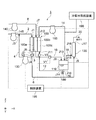
- FIG. 1 is a schematic configuration diagram of an entire fuel cell system.
- FIG. 3 is a top view showing the internal structure of a polymer electrolyte fuel cell stack. The figure which shows the AA' cross section of FIG. 2 typically.
- the flowchart which shows the control example of the fuel cell system 1 which concerns on 1st Embodiment.
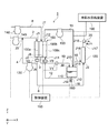
- the schematic block diagram of the whole fuel cell system which concerns on 2nd Embodiment.
- FIG. 1 is a schematic configuration diagram of the entire fuel cell system 1.
- the fuel cell system 1 is a system capable of reusing the anode off gas discharged from the fuel electrode of the fuel cell during power generation, and includes a fuel gas supply pipe 2, a fuel gas discharge pipe 3, 6, a fuel gas recycling pipe 4, an oxygen-containing gas supply pipe 8, a first oxygen-containing gas discharge pipe 10, a cooling water supply pipe 12, a cooling water discharge pipe 14, a stored water discharge pipe 16, a second Oxygen-containing gas exhaust pipe 18, external exhaust pipe 20, fuel cell stack 100, cooling water tank 110, pressure loss unit 120, first supply unit 130, second supply unit 140, and third supply unit. 145, the discharge part 150, the discharge valve part 180, the cooling water supply device 190, and the control device 195, and are comprised.
- FIG. 1 further shows atmospheric pressure measuring instruments V1 and V2 and a water pressure measuring instrument V3.
- FIG. 2 is a top view showing the internal structure of the polymer electrolyte fuel cell stack 100.
- the fuel cell stack 100 includes a fuel cell 115, a fuel inlet manifold 200, a fuel outlet manifold 202, an air inlet manifold 204, an air outlet manifold 206, and a cooling water inlet manifold 208. And a cooling water outlet manifold 210.
- the fuel cell unit 115 is an electromotive unit, and the detailed configuration will be described later.
- the fuel inlet manifold 200, the fuel outlet manifold 202, the air inlet manifold 204, the air outlet manifold 206, the cooling water inlet manifold 208, and the cooling water outlet manifold 210 are provided around the fuel cells 115.
- the fuel gas supply pipe 2 is connected to the inlet portion J1 of the fuel inlet manifold 200 of the fuel cell stack 100.
- a hydrogen-containing gas is supplied to the fuel gas supply pipe 2 as a fuel gas.
- the fuel gas supply pipe 2 constitutes a fuel gas flow passage for supplying the fuel gas to the fuel electrode flow passage 100 a of the fuel cell stack 100.
- the fuel gas discharge pipes 3 and 6 have one end connected to the outlet portion J2 of the fuel outlet manifold 202 of the fuel cell stack 100 and the other end connected to the inlet portion J5 of the pressure loss portion 120 via the branch portion J4. That is, the fuel gas discharge pipe 3 is a fuel gas discharge pipe from the outlet portion J2 of the fuel outlet manifold 202 to the branch portion J4, and the fuel gas discharge pipe 6 is from the branch portion J4 to the inlet portion J5 of the pressure loss portion 120. Is a fuel gas discharge pipe.
- the fuel gas discharge pipes 3 and 6 form a fuel gas discharge flow passage for discharging the anode off gas.
- the fuel gas recycle pipe 4 is connected to the branch portion J4 of the fuel gas discharge pipes 3 and 6, and the other end is connected to the confluence portion J3 of the fuel gas supply pipe 2.
- the fuel gas recycling pipe 4 circulates the anode off-gas discharged from the fuel electrode flow passage 100a of the fuel cell stack 100 through the confluence J3 of the fuel gas supply pipe 2.
- the fuel gas recycle pipe 4 constitutes a fuel gas recycle passage for circulating the anode off gas through the confluence J3 of the fuel gas supply pipe 2.
- the oxygen-containing gas supply pipe 8 is connected to the inlet portion J7 of the air inlet manifold 204 of the fuel cell stack 100.
- air is supplied to the oxygen-containing gas supply pipe 8 as the oxygen-containing gas.
- the oxygen-containing gas supply pipe 8 constitutes an oxygen-containing gas supply passage for supplying the oxygen-containing gas to the oxidizing pole passage of the fuel cell stack 100.
- the first oxygen-containing gas discharge pipe 10 constitutes a first oxygen-containing gas discharge flow passage for discharging the cathode off gas from the oxidizing pole flow passage 100b of the fuel cell stack 100 to the cooling water tank 110.
- the cooling water supply pipe 12 constitutes a cooling water supply passage for supplying the cooling water from the cooling water tank 110 to the inlet portion J11 of the cooling water inlet manifold 208.
- the cooling water supply port J10 is provided on the bottom surface of the cooling water tank 110.
- the cooling water discharge pipe 14 has one end connected to the outlet J12 of the cooling water outlet manifold 210 of the fuel cell stack 100 and the other end connected to the second inlet J13 of the cooling water tank 110.
- the cooling water discharge pipe 14 constitutes a cooling water discharge passage for discharging the cooling water from the cooling water outlet manifold 210 to the cooling water tank 110.
- the water storage discharge pipe 16 has one end connected to the branch portion J14 of the cooling water discharge pipe 14 and discharges a part of the cooling water stored in the cooling water tank 110. That is, the water discharge pipe 16 is provided with the opening/closing valve 180, and a part of the cooling water is discharged when the valve is open.
- the stored water discharge pipe 16 constitutes a stored water discharge flow passage for discharging the cooling water from the cooling water tank 110.
- the second oxygen-containing gas discharge pipe 18 has one end connected to the air discharge port J15 of the cooling water tank 110 and the other end connected to the second inlet J16 of the pressure loss unit 120.
- the second oxygen-containing gas discharge pipe 18 constitutes a second oxygen-containing gas discharge flow passage for discharging the cathode off gas from the cooling water tank 110 to the pressure loss portion 120.
- the external discharge pipe 20 has one end connected to the discharge portion J17 of the pressure loss portion 120, and discharges the anode off gas supplied from the fuel gas discharge pipe 6 and the cathode off gas supplied from the second oxygen-containing gas discharge pipe 18. To do.
- the external exhaust pipe 20 constitutes an external exhaust flow passage for exhausting the anode off gas and the cathode off gas.
- the fuel cell stack 100 includes a fuel electrode flow passage 100a for supplying a hydrogen-containing gas to a fuel electrode therein, an oxidant electrode flow passage 100b for supplying an oxygen-containing gas to an oxidant electrode, and cooling for cooling the fuel cell stack 100.
- the water flow passage 100c is provided, and electric power is generated using the hydrogen-containing gas supplied to the fuel electrode and the oxygen-containing gas supplied to the oxidant electrode.
- the anode off gas is a gas discharged from the fuel electrode passage 100a during power generation of the fuel cell stack 100, and contains unreacted fuel gas.
- the cathode off gas is a gas discharged from the oxidant polar flow passage 100b during power generation of the fuel cell stack 100.
- the fuel inlet manifold 200 and the fuel outlet manifold 202 are in communication with the fuel electrode flow passage 100a. That is, the fuel gas supplied from the inlet portion J1 of the fuel inlet manifold 200 is discharged from the outlet portion J2 of the fuel outlet manifold 202 via the fuel pole flow passage 100a shown by the dotted line.
- the air inlet manifold 204 and the air outlet manifold 206 communicate with the oxidant polar flow passage 100b. That is, the oxygen-containing gas supplied from the inlet portion J7 of the air inlet manifold 204 is discharged from the outlet portion J8 of the air outlet manifold 206 via the oxidant polar flow passage 100b shown by the broken line.
- the cooling water inlet manifold 208 and the cooling water outlet manifold 210 communicate with the cooling water flow passage 100c. That is, the cooling water supplied from the inlet portion J11 of the cooling water inlet manifold 208 is discharged from the outlet portion J12 of the cooling water outlet manifold 210 via the cooling water flow passage 100c shown by the solid line.
- thermoplastic resin or thermosetting resin is compression-molded or injection-molded by a mold. It is manufactured by Examples of the thermoplastic resin used for this purpose include polyphenylene sulfide (PPS), and examples of the thermosetting resin include epoxy resin and phenol resin.
- thermoplastic resin used for this purpose include polyphenylene sulfide (PPS), and examples of the thermosetting resin include epoxy resin and phenol resin.
- PPS polyphenylene sulfide
- thermosetting resin include epoxy resin and phenol resin.
- Each manifold has a box-like shape with an opening on the side of the fuel cell 115, and a side surface and an inner surface of the manifold are provided with a draft taper from the side of the fuel cell 115 toward the bottom surface of the manifold. The mold releasability of is secured.
- a seal groove having a rectangular cross section is provided over the entire circumference of the peripheral sealing surface of the manifold, which is in contact with the side surface of the fuel cell 115.
- a sealant is inserted in the seal groove to prevent gas/cooling water leaks.
- the cooling water tank 110 is connected with a first oxygen-containing gas discharge pipe 10, a cooling water supply pipe 12, a cooling water discharge pipe 14, and a second oxygen-containing gas discharge pipe 18. That is, the other end of the first oxygen-containing gas discharge pipe 10 whose one end is connected to the outlet portion J8 of the air outlet manifold 206 provided on the downstream side of the oxidant pole flow passage 100b is connected to the inlet portion J9, and the cooling water flow passage is connected. Cooling provided on the upstream side of the cooling water flow passage 100c, which is connected to the other end of the cooling water discharge pipe 14 whose one end is connected to the outlet portion J12 of the cooling water outlet manifold 210 provided on the downstream side of 100c and an inlet portion J13.
- the other end of the cooling water supply pipe 12 whose one end is connected to the inlet J11 of the water inlet manifold 208 is connected to the cooling water supply J10.
- the water pressure in the cooling water inlet manifold 208 of the fuel cell stack 100 is adjusted to be equal to or lower than the atmospheric pressure of the air outlet manifold 206 by the cooling water tank 110 and these piping configurations 10, 12, and 14.
- the cooling water tank 110 can be supplied with cooling water from the cooling water supply device 190. Thereby, the amount of water stored in the cooling water tank 110 can be increased.
- the pressure loss portion 120 is connected to the other end of the second oxygen-containing gas discharge pipe 18 having one end connected to the air discharge port J15 of the cooling water tank 110, and the fuel provided on the downstream side of the fuel pole passage 100a.
- the other end of the fuel gas discharge pipe 6 whose one end is connected to the outlet portion J2 of the outlet manifold 202 is connected.
- the pressure loss unit 120 adjusts the atmospheric pressure in the first oxygen-containing gas exhaust pipe 10, the cooling water tank 110, and the second oxygen-containing gas exhaust pipe 18, and the atmospheric pressure in the fuel gas exhaust pipe 6.
- the pressure loss part 120 may be configured by, for example, any one of a heat exchanger, a muffler duct, and a catalytic combustor. Details of the pressure loss unit 120 will be described later.
- the fuel gas discharge pipe 6 and the second oxygen-containing gas discharge pipe 18 may be joined together and then connected to the pressure loss portion 120.
- the pressure loss part 120 is assumed to include up to the confluence of the fuel gas discharge pipe 6 and the second oxygen-containing gas discharge pipe 18.
- the first supply unit 130 is, for example, a recycle blower, and is provided in the fuel gas recycling pipe 4 on the downstream side of the branch portion J4 of the fuel gas recycling pipe 4.
- the first supply unit 130 discharges the anode off gas from the downstream side of the fuel electrode, and discharges it to the downstream side of the first supply unit 130 of the fuel gas discharge pipe 6.
- the second supply unit 140 is, for example, a compressor, and is provided in the oxygen-containing gas supply pipe 8 on the upstream side of the inlet J7 of the air inlet manifold 204.
- the second supply unit 140 supplies the oxygen-containing gas from the upstream side of the oxidizer electrode.
- the oxidant gas is supplied to the oxygen-containing gas supply pipe 8, the oxidant polar flow passage 100b, the first oxygen-containing gas discharge pipe 10, the cooling water tank 110, the second oxygen-containing gas discharge pipe 18, the pressure loss portion 120,
- the atmospheric pressure decreases as it goes downstream in the flow path of the external discharge pipe 20.
- the atmospheric pressure in the air outlet manifold 206 becomes lower than the atmospheric pressure in the air inlet manifold 204, and the atmospheric pressure in the oxidant polar flow passage 100b decreases as it goes downstream of the oxidant polar flow passage 100b.
- the pressure in the cooling water tank 110 becomes lower than the atmospheric pressure in the air outlet manifold 206.
- the third supply unit 145 is, for example, a compressor, and is provided in the fuel gas supply pipe 2 upstream of the inlet J1 of the fuel inlet manifold 200.
- the third supply unit 145 supplies the fuel gas from the upstream side of the fuel electrode.
- the atmospheric pressure of the fuel gas decreases as it goes downstream in the flow path of the fuel gas supply pipe 2, the fuel electrode flow passage 100a, the fuel gas discharge pipes 3 and 6, the pressure loss portion 120, and the external discharge pipe 20. That is, the atmospheric pressure in the fuel outlet manifold 202 becomes lower than the atmospheric pressure in the fuel inlet manifold 200, and the atmospheric pressure in the fuel electrode flow passage 100a decreases as it goes downstream of the fuel electrode flow passage 100a.
- the pressure in the pressure loss portion 120 becomes lower than the atmospheric pressure in the fuel outlet manifold 202.
- the discharge part 150 is, for example, a cooling water pump, and is provided in the cooling water discharge pipe 14 on the downstream side of the outlet J12 of the cooling water outlet manifold 210.
- the discharge unit 150 discharges the cooling water on the cooling water flow passage 100c side in the cooling water discharge pipe 14 to the cooling water tank 110 side.
- the cooling water is discharged from the outlet portion J12 of the cooling water outlet manifold 210 by the discharge portion 150.
- the water pressure of the cooling water discharged from the discharge unit 150 decreases as it goes downstream of the discharge unit 150. That is, the pressure at the inlet portion J11 of the cooling water inlet manifold 208 is lower than the pressure inside the cooling water tank 110.
- the water pressure of the cooling water in the cooling water flow passage 100c of the fuel cell stack 100 decreases as it goes downstream of the cooling water flow passage 100c.
- the pressure inside the cooling water tank 110 becomes lower than the atmospheric pressure inside the air outlet manifold 206.
- the water pressure at the inlet portion J11 of the cooling water inlet manifold 208 becomes lower than the pressure inside the cooling water tank 110.
- the water pressure at the inlet portion J11 of the cooling water inlet manifold 208 is always lower than the atmospheric pressure at the outlet portion J8 of the air outlet manifold 206 with reference to the pressure in the cooling water tank 110.
- the water pressure in the cooling water flow passage 100c is always kept lower than the atmospheric pressure in the oxidant polar flow passage 100b.
- the operating pressure of the fuel cell stack 100 can be adjusted by increasing or decreasing the pressure in the cooling water tank 110.
- the operating pressure means the pressure in the fuel pole passage 100a and the oxidant pole passage 100b during the power generation of the fuel cell stack 100. That is, the operating pressure means the pressure of the reaction gas during the power generation of the fuel cell stack 100.
- the cooling water discharge pipe 14 is connected to the cooling water tank 110, if the pressure of the cooling water tank 110 is constant, the pressure drop of the cooling water flow passage 100c decreases when the discharge amount of the cooling water of the discharge part 150 increases. Is larger and the pressure at the cooling water manifold inlet 208 is lower. This makes it possible to adjust the differential pressure between the water pressure of the cooling water inlet manifold 208 and the air pressure of the air outlet manifold 206.
- the pressure loss portion 120 increases the pressure in the cooling water tank 110, and the water pressure of the cooling water inlet manifold 208 and the air pressure of the air outlet manifold 206 increase while maintaining the differential pressure. Further, the atmospheric pressure in the fuel outlet manifold 202 becomes higher than that in the pressure loss portion 120. Therefore, the air pressure inside the fuel outlet manifold 202 becomes higher than the water pressure inside the cooling water inlet manifold 208. As a result, the air pressure in the fuel electrode flow passage 100a is always maintained higher than the water pressure in the cooling water flow passage 100c. As described above, the cooling water tank 110 and the pressure loss portion 120 make the water pressure in the cooling water flow passage 100c always lower than the atmospheric pressure in the fuel electrode flow passage 100a and the oxidant electrode flow passage 100b, thereby flooding. Can be suppressed.
- the discharge valve unit 180 opens and closes the stored water discharge pipe 16 that controls the amount of stored water in the cooling water tank 110 under the control of the control device 195.
- the cooling water supply device 190 supplies the cooling water via the cooling water discharge pipe 14.
- the atmospheric pressure measuring device V1 measures the atmospheric pressure inside the first oxygen-containing gas discharge pipe 10.
- the atmospheric pressure measuring device V2 measures the atmospheric pressure in the fuel gas discharge pipe 3.
- the water pressure measuring device V3 measures the water pressure in the cooling water supply pipe 12.
- the control device 195 controls the entire fuel cell system 1.
- the control device 195 is, for example, a microcomputer including a CPU (Central Processing Unit), a storage device, an input/output device, and the like.
- the control device 195 controls according to the program stored in the storage device.
- the control device 195 controls the second supply unit 140, the discharge unit 150, the discharge valve unit 180, and the cooling water supply device 190 based on the signals from the atmospheric pressure measuring device V1 and the water pressure measuring device V3.
- the controller 195 also controls the first supply unit 130 to control the recycling flow rate in the fuel gas recycling pipe 4.
- FIG. 3 is a diagram schematically showing the AA′ cross section of FIG. 2.
- the fuel battery cell 115 is configured by stacking a plurality of unit batteries 100d.
- the unit battery 100d includes a membrane electrode assembly 100e, a fuel electrode flow passage separator 105, and an oxidant electrode flow passage separator 106.
- the membrane electrode assembly 100e includes a solid polymer electrolyte membrane 101, a fuel electrode (anode electrode) 103 arranged on one surface of the solid polymer electrolyte membrane, and a side of the solid polymer electrolyte membrane opposite to the fuel electrode 103. And an oxidizer electrode (cathode electrode) 104 disposed on the surface. Further, the fuel electrode 103 has an anode catalyst layer 103a, and the oxidant electrode 104 has a cathode catalyst layer 104a.
- the fuel electrode flow passage 100 a is formed in the separator 105 with the fuel electrode flow passage.
- an oxidant electrode flow passage 100b and a cooling water flow passage 100c are formed in the separator 106 with the oxidant electrode flow passage.
- the cooling water flow passage 100c is in contact with the fuel electrode flow passage 100a and the oxidant electrode flow passage 100b via the separator.
- the cooling water flow passage 100c is provided in the oxidant electrode flow passage separator 106, but the present invention is not limited to this, and the cooling water flow passage 100c may be provided in the fuel electrode flow passage separator 105.
- a separator for the cooling water flow passage 100c may be provided separately from the separator 106 with the oxidant electrode flow passage and the separator 105 with the fuel electrode flow passage. Further, in the present embodiment, the separator with fuel electrode flow passage 105 and the separator with oxidant electrode flow passage 106 are independent of each other, but they may be integrally formed.
- the plurality of unit batteries 100d generate power by the reaction shown in Chemical Formula 1.
- the hydrogen-containing gas flows through the fuel electrode flow passage 100a on the fuel electrode 103 side to cause a fuel electrode reaction.
- the oxygen-containing gas flows through the oxidant electrode flow passage 100b on the oxidant electrode 104 side to cause an oxidant electrode reaction.
- the fuel cell stack 100 utilizes these electrochemical reactions to extract electric energy from the electrodes.
- One of the performances of the fuel cell stack 100 is indicated by current-voltage characteristics.
- the actual voltage of the fuel cell stack 100 when a predetermined current flows is lower than the theoretical value.
- the separator 105 with the fuel electrode flow passage and the separator 106 with the oxidant electrode flow passage are configured by a porous type separator.
- the separator 105 with the fuel electrode flow passage and the separator 106 with the oxidant electrode flow passage are formed of a carbon porous body. These separators can contain water necessary for humidifying the electrolyte membrane inside the porous body. Further, by setting the pressure of the cooling water flow passage 100c to be lower than that of the fuel electrode flow passage 100a and the oxidant electrode flow passage 100b, the water generated by the electrode reaction is absorbed into the cooling water flow passage 100c via the separator, and the gas downstream Flooding on the side can be prevented. This can suppress an increase in diffusion overvoltage.
- the porous separator may be made of metal oxide.
- the second supply unit 140 supplies the oxygen-containing gas to the oxidant polar flow passage 100b of the fuel cell stack 100 via the oxygen-containing gas supply pipe 8.
- the oxygen-containing gas flowing into the oxidant electrode flow passage 100b is supplied to the oxidant electrode 104 of each unit cell 100d.
- Part of the oxygen-containing gas that has reached the oxidant electrode 104 receives the protons and electrons emitted from the fuel electrode and produces water, as shown in Chemical Formula 1 above.
- the cathode off gas discharged from the first oxygen-containing gas discharge pipe 10 is supplied to the cooling water tank 110.
- the cathode off gas supplied to the cooling water tank 110 is supplied to the pressure loss portion 120 via the second oxygen-containing gas discharge pipe 18.
- the pressure loss in the pressure loss unit 120 adjusts the pressure in the cooling water tank 110.
- the water pressure in the cooling water flow passage 100c and the water pressure in the oxidant polar flow passage 100b are adjusted by adjusting the discharge amount of the cooling water of the discharge part 150 based on the measured values of the atmospheric pressure measuring device V1 and the water pressure measuring device V3.
- the differential pressure between and is controlled.
- the hydrogen-containing gas is supplied to the fuel electrode flow passage 100a of the fuel cell stack 100 via the fuel gas supply pipe 2.
- the hydrogen-containing gas flowing into the fuel gas supply pipe 2 is supplied to the fuel electrode 103 of each unit cell 100d.
- Part of the hydrogen-containing gas that has reached the fuel electrode 103 is generated by the fuel electrode 103 as protons and electrons, as shown in the above chemical formula 1.
- Excess hydrogen-containing gas that has not been used for power generation is discharged to the fuel gas recycling pipe 4 from the outlet of the fuel electrode flow passage 100a of the fuel cell stack 100 as anode off-gas.
- the fuel gas recycle pipe 4 circulates the anode off gas discharged from the fuel electrode flow passage 100a through the confluence J3 of the fuel gas supply pipe 2. At this time, the first supply unit 130 discharges the anode off gas to the downstream side of the first supply unit 130 of the fuel gas recycling pipe 4 under the control of the control device 195.
- Part of the anode off gas discharged from the fuel gas discharge pipe 6 is discharged via the pressure loss portion 120.
- the pressure loss in the pressure loss portion 120 adjusts the pressure in the fuel pole flow passage 100a.
- a part of the cooling water supplied from the cooling water tank 110 to the cooling water flow passage 100c in the fuel cell stack 100 is supplied via the separator with fuel pole flow passage 105 and the separator with oxidant pole flow passage 106 to form a membrane. It is used for humidifying the electrode composite 100e.
- the cooling water in the cooling water flow passage 100c is discharged by the discharge unit 150 via the cooling water discharge pipe 14 and is discharged to the cooling water tank 110.
- the cooling water flow passage 100c is maintained at a lower pressure than the fuel electrode flow passage 100a and the oxidant electrode flow passage 100b, the water generated by the electrode reaction is generated by the separator 105 with the fuel electrode flow passage and the oxidizer. It is absorbed in the cooling water flow passage 100c via the separator 106 with the polar flow passage. As a result, there is no generated water on the downstream side of the fuel pole flow passage 100a and the oxidant pole flow passage 100b, and flooding is suppressed.
- FIG. 4 is a flowchart showing a control example of the fuel cell system 1 according to the first embodiment.
- an example of controlling the supply amount of the second supply unit 140 and the discharge amount of the discharge unit 150 after the discharge unit 150 is adjusted to a predetermined value will be described.
- control device 195 starts controlling the supply amount of the second supply unit 140 and the discharge unit amount of the discharge unit 150 using the initial values stored in the storage device (step S100).
- control device 195 acquires the measurement value of the atmospheric pressure measuring device V1 (step S102). As a result, the air pressure inside the air outlet manifold 206 is acquired.
- control device 195 acquires the measurement value of the water pressure measuring device V3 (step S104). As a result, the water pressure in the cooling water inlet manifold 208 is acquired.
- the control device 195 determines whether or not the differential pressure between the air pressure at the outlet portion J8 of the air outlet manifold 206 and the water pressure at the inlet portion J11 of the cooling water inlet manifold 208 is a predetermined value (step S106). .. When the differential pressure is not the predetermined value (NO in step S106), the control device 195 increases the discharge amount of the discharge unit 150 by a predetermined amount when increasing the differential pressure, and conversely, when increasing the pressure difference, decreases the discharge amount by a predetermined amount. The process from step S102 is continued for a while (step S108). ..
- step S110 determines whether to end the entire process.
- step S110 determines whether to end the entire process.
- the process from step S102 is repeated.
- the atmospheric pressure of the outlet portion J8 of the air outlet manifold 206 is kept at the cooling water inlet manifold 208 by the action of the cooling water tank 100 and the pipe configurations 10, 12, and 14 and the like. It is always maintained higher than the water pressure at the inlet J11 of the.
- control device 195 stores the control value of the second supply unit 140 and the control value of the discharge unit 150 in the storage device (step S112), and the whole process. The process ends.
- the discharge amount of the discharge part 150 by adjusting the discharge amount of the discharge part 150, the differential pressure between the water pressure of the cooling water supplied from the cooling water tank 100 to the inlet part of the cooling water flow passage 100c and the atmospheric pressure of the discharge part of the oxidizing polar flow passage 100b is adjusted. I decided to adjust it. As a result, it is possible to adjust the differential pressure between the water pressure in the cooling water flow passage 100c and the atmospheric pressure in the oxidant polar flow passage 100b only by adjusting the discharge amount in the discharge section 150.
- the other end of the cooling water supply pipe 12 connected to the cooling water inlet manifold 208 is connected to the cooling water supply port J10, and one end is connected to the air outlet manifold 206.
- the other end of the second oxygen-containing gas exhaust pipe 18 whose one end is connected to the air exhaust port J15 of the cooling water tank 110, and the fuel pole passage 100a.
- the fuel cell system 1 according to the present embodiment differs from the fuel cell system 1 according to the first embodiment in that a damper 215 is further provided on the external discharge pipe 20.
- a damper 215 is further provided on the external discharge pipe 20.
- FIG. 5 is a schematic configuration diagram of the entire fuel cell system 1 according to the second embodiment. As shown in FIG. 5, the fuel cell system 1 according to the second embodiment further includes a damper 215.
- the damper 215 adjusts the pressure loss of the external discharge pipe 20. This makes it possible to adjust the pressure increase between the air pressure at the outlet J8 of the air outlet manifold 206 and the air pressure at the outlet J2 of the fuel outlet manifold 202.
- the pressure inside the cooling water tank 110 is adjusted by the damper 215 provided on the external discharge pipe 20. Accordingly, while maintaining the water pressure of the cooling water supplied to the inlet portion J11 of the cooling water flow passage 100c lower than that of the discharge portion J8 of the oxidizing pole flow passage 100b, the discharging portion J8 of the oxidizing pole flow passage 100b and the fuel outlet manifold 202. It is possible to adjust the atmospheric pressure at the outlet J2 of the.
Landscapes
- Life Sciences & Earth Sciences (AREA)
- Engineering & Computer Science (AREA)
- Manufacturing & Machinery (AREA)
- Sustainable Development (AREA)
- Sustainable Energy (AREA)
- Chemical & Material Sciences (AREA)
- Chemical Kinetics & Catalysis (AREA)
- Electrochemistry (AREA)
- General Chemical & Material Sciences (AREA)
- Fuel Cell (AREA)
Abstract
本実施形態に係る燃料電池システムは、燃料電池スタックと、冷却水入口マニホールドと連結した冷却水供給管の他端が冷却水供給口部と連結し、空気出口マニホールドと一端が連結した第1酸素含有ガス排出管の他端が連結した冷却水タンクであって、冷却水入口マニホールドから冷却水を供給する冷却水タンクと、冷却水タンクの空気排出口部と一端が連結した第2酸素含有ガス排出管の他端と連結し、燃料極流通路の下流側出口に設けられた燃料出口マニホールドと一端が連結した燃料ガス排出管の他端が連結された圧力損失部と、を備える。
Description
本発明の実施形態は、燃料電池システム、及び燃料電池システムの制御方法に関する。
燃料極、固体高分子電解質膜、酸化剤極、セパレータを層状に構成した固体高分子形燃料電池スタックでは、燃料極に水素を含む燃料ガスが供給され、酸化剤極に酸素を含む酸素含有ガスが供給され、電気化学反応により発電を行う。一方、固体高分子電解質膜は平衡する水蒸気圧により膜の含水率が変化し、電解質膜の抵抗が変化する特性がある。このため、電解質膜の抵抗を小さくし、十分な発電性能を得るためには固体高分子電解質膜への加湿が必要となる。加湿方式として、燃料ガスや酸化剤ガスに予め水蒸気を添加する外部加湿方式と、セパレータを介して水を直接添加する内部加湿方式とが一般に知られている。
また、電池反応の発熱を取り除くため、冷却する必要が生じる。冷却は複数セル毎に冷却板を挿入し、冷却板に水または空気を流して冷却する方法、内部加湿により供給した水の蒸発潜熱により冷却する方法などがある。加湿方法と冷却方法には密接な関係がある。外部加湿方式では運転条件の発熱状態に応じて数セルおきに冷却水流通路が挿入される。セパレータには緻密な導電性材料が使われ、燃料ガス流通路、酸化剤ガス流通路、及び冷却水流通路を形成するとともに、リークを防ぐ構成となっている。このセパレータの両面に流通路を設けると、セパレータの枚数は1セル当り1~2枚となる。
内部加湿・潜熱冷却方式では、ガス流通路と同じセパレータ面に設けた冷却水流通路からガス流通路に加湿水を供給し、加湿水の蒸発潜熱により冷却を行う。セパレータには緻密な導電性材料が使われ、リークを防ぐ構成となっている。冷却板が省略でき、セパレータの枚数は1セル当たり1枚である。外部加湿方式、及び内部加湿・潜熱冷却水方式では、反応による生成水は水蒸気として回収され、未反応のガスとともに排出される。電解質膜の抵抗を小さく保つため、ガス流通路の水蒸気圧は高くなり、セパレータとして緻密な材料を用いるため、水分の凝縮が起こって燃料極および酸化剤極内のガス拡散層を閉塞してガスの拡散が妨げられる。この現象はフラッディングと呼ばれ、固体高分子型燃料電池の性能劣化の要因の1つとなる。
微孔のある導電性多孔質板を使用した加湿・冷却方法では、一般に各セルに冷却水流通路を設けて導電性多孔質板を介して冷却水をガス流通路に供給して加湿する。この場合、生成水や凝縮した水分は導電性多孔質板を介して除去される。このため、燃料ガスと酸化剤ガスの圧力を冷却水の圧力よりも高くして、ガスのリークを防ぐとともに、反応面内での均一な加湿と冷却が行われる。また、酸化剤ガス流通路と、冷却水流通路の間に圧力調整容器を設けて、酸化剤ガスを加圧した場合の、酸化剤ガスと冷却水との差圧を生成している。
ところが、酸化剤ガスと冷却水との差圧の制御については、酸化剤ガス流通路と冷却水流通路の各々に分岐配管が必要であり、さらに圧力調整用の容器が必要になるなど、システムが複雑になってしまう。
発明が解決しようとする課題は、燃料極流通路内の燃料ガス及び酸化剤極流通路内の酸化剤ガスの内の少なくとも一方の圧力を冷却水流通路内の冷却水の圧力よりも高く維持した状態で作動圧力を調整可能な燃料電池システム、及び燃料電池システムの制御方法を提供することである。
本実施形態に係る燃料電池システムは、燃料ガス供給流通路から供給される燃料ガスを燃料極に供給する燃料極流通路と、酸化剤極に酸素含有ガスを供給する酸化剤極流通路と、前記燃料極流通路及び前記酸化剤極流通路の内の少なくとも一方に対し導電性多孔質材料で隔離した冷却水流通路とを設けた燃料電池スタックと、一端が前記冷却水流通路の上流側入口に設けられた冷却水入口マニホールドと連結した冷却水供給管の他端が冷却水供給口部と連結し、前記酸化剤極流通路の下流側に設けられた空気出口マニホールドと一端が連結した第1酸素含有ガス排出管の他端が連結した冷却水タンクであって、前記冷却水入口マニホールドから冷却水を供給する冷却水タンクと、前記冷却水タンクの空気排出口部と一端が連結した第2酸素含有ガス排出管の他端と連結し、前記燃料極流通路の下流側出口に設けられた燃料出口マニホールドと一端が連結した燃料ガス排出管の他端が連結された圧力損失部と、を備える。
本実施形態に係る燃料電池システムの制御方法は、燃料ガス供給流通路から供給される燃料ガスを燃料極に供給する燃料極流通路と、酸化剤極に酸素含有ガスを供給する酸化剤極流通路と、前記燃料極流通路及び前記酸化剤極流通路の内の少なくとも一方に対し導電性多孔質材料で隔離した冷却水流通路とを設けた燃料電池スタックと、一端が前記冷却水流通路の上流側入口に設けられた冷却水入口マニホールドと連結した冷却水供給管の他端が冷却水供給口部と連結し、前記酸化剤極流通路の下流側に設けられた空気出口マニホールドと一端が連結した第1酸素含有ガス排出管の他端が連結した冷却水タンクであって、前記冷却水入口マニホールドから冷却水を供給する冷却水タンクと、前記冷却水タンクの空気排出口部と一端が連結した第2酸素含有ガス排出管の他端と連結し、前記燃料極流通路の下流側出口に設けられた燃料出口マニホールドと一端が連結した燃料ガス排出管の他端が連結された圧力損失部と、を備えた燃料電池システムの制御方法であって、前記冷却水入口マニホールドにおける水圧と、前記酸化剤極流通路の下流側に設けられた空気出口マニホールドの気圧との差圧を前記冷却水流通路からの吐出量により調整する。
本発明によれば、燃料極流通路内の燃料ガス及び酸化剤極流通路内の酸化剤ガスの内の少なくとも一方の圧力を冷却水流通路内の冷却水の圧力よりも高く維持した状態で作動圧力を調整することができる。
以下、本発明の実施形態に係る燃料電池システム、及び燃料電池システムの制御方法について、図面を参照しながら詳細に説明する。なお、以下に示す実施形態は、本発明の実施形態の一例であって、本発明はこれらの実施形態に限定して解釈されるものではない。また、本実施形態で参照する図面において、同一部分又は同様な機能を有する部分には同一の符号又は類似の符号を付し、その繰り返しの説明は省略する場合がある。また、図面の寸法比率は説明の都合上実際の比率とは異なる場合や、構成の一部が図面から省略される場合がある。
(第1実施形態)
(第1実施形態)
まず、図1及び図2に基づき、先ず燃料電池システム1の全体構成を説明する。図1は、燃料電池システム1の全体の概略構成図である。この図1に示すように、燃料電池システム1は、発電中に燃料電池の燃料極から排出されるアノードオフガスを再利用可能なシステムであり、燃料ガス供給管2と、燃料ガス排出管3、6と、燃料ガスリサイクル管4と、酸素含有ガス供給管8と、第1酸素含有ガス排出管10と、冷却水供給管12と、冷却水排出管14と、貯水排出管16と、第2酸素含有ガス排出管18と、外部排出管20と、燃料電池スタック100と、冷却水タンク110と、圧力損失部120と、第1供給部130と、第2供給部140と、第3供給部145と、排出部150と、排出弁部180と、冷却水供給装置190と、制御装置195と、を備えて構成されている。図1には、更に気圧計測器V1、V2と、水圧計測器V3と、が図示されている。
図2は、固体高分子型の燃料電池スタック100の内部構造を示す上面図である。図2に示すように、燃料電池スタック100は、燃料電池セル115と、燃料入口マニホールド200と、燃料出口マニホールド202と、空気入口マニホールド204と、空気出口マニホールド206と、冷却水入口マニホールド208と、冷却水出口マニホールド210とを、有している。燃料電池セル115は起電部であり、詳細な構成は後述する。このように、燃料電池セル115の周りには、燃料入口マニホールド200、燃料出口マニホールド202、空気入口マニホールド204、空気出口マニホールド206、冷却水入口マニホールド208、冷却水出口マニホールド210が設けられている。
燃料ガス供給管2は、燃料電池スタック100の燃料入口マニホールド200の入口部J1に接続されている。燃料ガス供給管2には、燃料ガスとして水素含有ガスが供給される。これにより、燃料ガス供給管2は、燃料ガスを燃料電池スタック100の燃料極流通路100aに燃料ガスを供給する燃料ガス流通路を構成する。
燃料ガス排出管3、6は、一端が燃料電池スタック100の燃料出口マニホールド202の出口部J2に接続され他端が分岐部J4を介して圧力損失部120の入口部J5に接続されている。すなわち、燃料ガス排出管3は、燃料出口マニホールド202の出口部J2から分岐部J4までの燃料ガス排出管であり、燃料ガス排出管6は、分岐部J4から圧力損失部120の入口部J5までの燃料ガス排出管である。この燃料ガス排出管3、6は、アノードオフガスを排出する燃料ガス排出流通路を構成する。
燃料ガスリサイクル管4は、燃料ガス排出管3、6の分岐部J4に接続され、他端が燃料ガス供給管2の合流部J3に接続されている。燃料ガスリサイクル管4は、燃料電池スタック100の燃料極流通路100aから排出されたアノードオフガスを燃料ガス供給管2の合流部J3を介して環流させる。これにより、燃料ガスリサイクル管4は、アノードオフガスを燃料ガス供給管2の合流部J3を介して環流させる燃料ガスリサイクル流通路を構成する。
酸素含有ガス供給管8は、燃料電池スタック100の空気入口マニホールド204の入口部J7に接続されている。酸素含有ガス供給管8には、酸素含有ガスとして例えば空気が供給される。これにより、酸素含有ガス供給管8は、燃料ガスを燃料電池スタック100の酸化極流通路に酸素含有ガスを供給する酸素含有ガス供給流通路を構成する。
第1酸素含有ガス排出管10は、一端が燃料電池スタック100の空気出口マニホールド206の出口部J8に接続され、他端が冷却水タンク110の第1入口部J9に接続されている。この第1酸素含有ガス排出管10は、燃料電池スタック100の酸化極流通路100bからカソードオフガスを冷却水タンク110に排出する第1酸素含有ガス排出流通路を構成する。
冷却水供給管12は、一端が冷却水タンク110の冷却水供給口部J10と連結し、他端が燃料電池スタック100の冷却水流通路100cの上流側に設けられた冷却水入口マニホールド208の入口部と連結する。この冷却水供給管12は、冷却水タンク110から冷却水を冷却水入口マニホールド208の入口部J11に供給する冷却水供給流通路を構成する。冷却水供給口部J10は、冷却水タンク110の底面部に設けられている。
冷却水排出管14は、一端が燃料電池スタック100の冷却水出口マニホールド210の出口部J12と連結し、他端が冷却水タンク110の第2入口部J13と連結する。この冷却水排出管14は、冷却水出口マニホールド210から冷却水を冷却水タンク110に排出する冷却水排出流通路を構成する。
貯水排出管16は、一端が冷却水排出管14の分岐部J14と連結し、冷却水タンク110に貯水された冷却水の一部を排出する。すなわち、貯水排出管16には開閉弁180が設けられており、弁が開状態のときに、冷却水の一部が排出される。この貯水排出管16は、冷却水タンク110から冷却水を排出する貯水排出流通路を構成する。
第2酸素含有ガス排出管18は、一端が冷却水タンク110の空気排出口部J15に接続され、他端が圧力損失部120の第2入口部J16に接続されている。この第2酸素含有ガス排出管18は、カソードオフガスを冷却水タンク110から圧力損失部120に排出する第2酸素含有ガス排出流通路を構成する。
外部排出管20は、一端が圧力損失部120の排出部J17と接続され、燃料ガス排出管6から供給されたアノードオフガスと、第2酸素含有ガス排出管18から供給されたカソードオフガスとを排出する。外部排出管20は、アノードオフガスとカソードオフガスとを排出する外部排出流通路を構成する。
燃料電池スタック100は、内部に水素含有ガスを燃料極に供給する燃料極流通路100aと、酸化剤極に酸素含有ガスを供給する酸化剤極流通路100bと、燃料電池スタック100を冷却する冷却水流通路100cを有し、燃料極に供給される水素含有ガスと、酸化剤極に供給される酸素含有ガスとを用いて発電する。ここで、アノードオフガスは、燃料電池スタック100の発電中に燃料極流通路100aから排出されるガスであり、未反応の燃料ガスが含まれている。カソードオフガスは、燃料電池スタック100の発電中に酸化剤極流通路100bから排出されるガスである。
図2に示すように、燃料入口マニホールド200、及び燃料出口マニホールド202は、燃料極流通路100aと連通している。すなわち、燃料入口マニホールド200の入口部J1から供給された燃料ガスは、点線で示した燃料極流通路100aを経由して、燃料出口マニホールド202の出口部J2から排出される。
空気入口マニホールド204、及び空気出口マニホールド206は、酸化剤極流通路100bと連通している。すなわち、空気入口マニホールド204の入口部J7から供給された酸素含有ガスは、破線で示した酸化剤極流通路100bを経由して、空気出口マニホールド206の出口部J8から排出される。
冷却水入口マニホールド208、及び冷却水出口マニホールド210は、冷却水流通路100cと連通している。すなわち、冷却水入口マニホールド208の入口部J11から供給された冷却水は、実線で示した冷却水流通路100cを経由して、冷却水出口マニホールド210の出口部J12から排出される。
各マニホールド200,202,204,206,208,210は、ガス不透過性と電気絶縁性を有することが必要であり、通常、熱可塑性樹脂もしくは熱硬化性樹脂を金型により圧縮成形もしくはインジェクション成形することにより製造される。これに用いる熱可塑性樹脂としてはポリフェニレンサルファイド(PPS)、熱硬化性樹脂としてはエポキシ樹脂やフェノール樹脂などが挙げられる。各マニホールドは、燃料電池セル115側を開口部とした箱状の形状を有し、マニホールドの側面および内面に燃料電池セル115側からマニホールド底面に向かって抜きテーパが設けられ、それによって金型からの離型性が確保されている。
燃料電池セル115の側面に接するマニホールドの周縁部のシール面には、断面が矩形のシール溝が周縁部全周にわたって設けられている。シール溝にはシール材が挿入されており、これによってガス/冷却水のリークを防いでいる。なお、燃料電池スタック100の詳細な構成は後述する。
図1に示すように、冷却水タンク110には、第1酸素含有ガス排出管10、冷却水供給管12、冷却水排出管14、第2酸素含有ガス排出管18、が接続されている。すなわち、酸化剤極流通路100bの下流側に設けられた空気出口マニホールド206の出口部J8と一端が連結した第1酸素含有ガス排出管10の他端と入口部J9で連結し、冷却水流通路100cの下流側に設けられた冷却水出口マニホールド210の出口部J12と一端が連結した冷却水排出管14の他端と入口部J13で連結し、冷却水流通路100cの上流側に設けられた冷却水入口マニホールド208の入口部J11と一端が連結した冷却水供給管12の他端が冷却水供給口部J10と連結している。これにより、冷却水タンク110とこれらの配管構成10、12、14などとにより、燃料電池スタック100の冷却水入口マニホールド208における水圧が、空気出口マニホールド206の気圧以下となるように調整される。また、冷却水タンク110には、冷却水供給装置190から冷却水の供給を受けることが可能である。これにより、冷却水タンク110内の貯水量を増加することができる。
圧力損失部120には、冷却水タンク110の空気排出口部J15と一端が連結した第2酸素含有ガス排出管18の他端が連結され、燃料極流通路100aの下流側に設けられた燃料出口マニホールド202の出口部J2と一端が連結した燃料ガス排出管6の他端が連結される。この圧力損失部120は、第1酸素含有ガス排出管10、冷却水タンク110内、及び第2酸素含有ガス排出管18内の気圧と、燃料ガス排出管6内の気圧を調整する。圧力損失部120は、例えば熱交換器、消音ダクト、及び触媒燃焼器のいずれか一つで構成してもよい。圧力損失部120の詳細は後述する。なお、燃料ガス排出管6と第2酸素含有ガス排出管18とを合流させた後に圧力損失部120に連結させてもよい。この場合、圧力損失部120は、燃料ガス排出管6と第2酸素含有ガス排出管18との合流部までを含むこととする。
第1供給部130は、例えばリサイクルブロアであり、燃料ガスリサイクル管4の分岐部J4よりも下流側の燃料ガスリサイクル管4に設けられている。この第1供給部130は、アノードオフガスを燃料極の下流側から排出し、燃料ガス排出管6の第1供給部130より下流側に排出する。
第2供給部140は例えばコンプレッサであり、空気入口マニホールド204の入口部J7よりも上流側の酸素含有ガス供給管8に設けられている。この第2供給部140は、酸素含有ガスを酸化剤極の上流側から供給する。これにより、酸化剤ガスは、酸素含有ガス供給管8、酸化剤極流通路100b、第1酸素含有ガス排出管10、冷却水タンク110、第2酸素含有ガス排出管18、圧力損失部120、及び外部排出管20の流路を下流に行くに従い気圧が低下する。すなわち、空気入口マニホールド204内の気圧よりも空気出口マニホールド206内の気圧が低くなり、酸化剤極流通路100b内の気圧は、酸化剤極流通路100bの下流に行くに従い気圧が低下する。同様に、冷却水タンク110内の圧力は、空気出口マニホールド206内の気圧よりも低くなる。
第3供給部145は、例えばコンプレッサであり、燃料入口マニホールド200の入口部J1よりも上流側の燃料ガス供給管2に設けられている。この第3供給部145は、燃料ガスを燃料極の上流側から供給する。これにより、燃料ガスは、燃料ガス供給管2、燃料極流通路100a、燃料ガス排出管3、6、圧力損失部120、及び外部排出管20の流路を下流に行くに従い気圧が低下する。すなわち、燃料入口マニホールド200内の気圧よりも燃料出口マニホールド202内の気圧が低くなり、燃料極流通路100a内の気圧は、燃料極流通路100aの下流に行くに従い気圧が低下する。同様に、圧力損失部120内の圧力は、燃料出口マニホールド202内の気圧よりも低くなる。
排出部150は、例えば冷却水ポンプであり、冷却水出口マニホールド210の出口部J12よりも下流側の冷却水排出管14に設けられている。これにより、排出部150は、冷却水排出管14内の冷却水流通路100c側の冷却水を冷却水タンク110側に排出する。このように、冷却水出口マニホールド210の出口部J12から排出部150により冷却水が排出される。これにより、排出部150から排出された冷却水は、排出部150の下流に行くに従い水圧が低下する。すなわち、冷却水タンク110内の圧力よりも冷却水入口マニホールド208の入口部J11の圧力の方が低くなる。同様に、燃料電池スタック100の冷却水流通路100c内の冷却水の水圧は、冷却水流通路100cの下流に行くに従い低下する。
上述のように、冷却水タンク110内の圧力は、空気出口マニホールド206内の気圧よりも低くなる。一方で、冷却水入口マニホールド208の入口部J11における水圧は冷却水タンク110内の圧力よりも低くなる。これらから分かるように、冷却水タンク110内の圧力を基準として、冷却水入口マニホールド208の入口部J11における水圧は空気出口マニホールド206の出口部J8の気圧よりも常に低圧となる。これにより、冷却水流通路100c内の水圧は常に酸化剤極流通路100b内の気圧より低く維持される。また、冷却水タンク110内の圧力の増減により、冷却水入口マニホールド208の水圧と、空気出口マニホールド206の気圧は、差圧を維持した状態で増減する。これにより、燃料電池スタック100の作動圧を冷却水タンク110内の圧力の増減により調整可能となる。ここで作動圧とは、燃料電池スタック100の発電中における燃料極流通路100a内、及び酸化剤極流通路100b内、の圧力を意味する。すなわち、作動圧とは、燃料電池スタック100の発電中における反応ガスの圧力を意味する。
一方で、冷却水排出管14は冷却水タンク110に接続されているので、冷却水タンク110の圧力が一定とすると、排出部150の冷却水の吐出量が多くなると冷却水流通路100cの圧力低下がより大きくなり、冷却水マニホールド入口208の圧力はより低下する。これにより、冷却水入口マニホールド208の水圧と、空気出口マニホールド206の気圧との差圧を調整可能となる。
ここで、圧力損失部120の作用を説明する。圧力損失部120により、冷却水タンク110内の圧力が増加し、冷却水入口マニホールド208の水圧と、空気出口マニホールド206の気圧は、差圧を維持した状態で増加する。また、燃料出口マニホールド202内の気圧は圧力損失部120よりも高くなる。このため、燃料出口マニホールド202内の気圧は冷却水入口マニホールド208の水圧よりも高くなる。これにより、燃料極流通路100a内の気圧は冷却水流通路100c内の水圧よりも常に高く維持される。このように、冷却水タンク110と圧力損失部120とにより、冷却水流通路100c内の水圧を燃料極流通路100a内及び酸化剤極流通路100b内の気圧より常に低い圧力とすることで、フラッディングを抑制することが可能となる。
排出弁部180は、制御装置195の制御により冷却水タンク110の貯水量を調節する貯水排出管16を開閉する。
冷却水供給装置190は、冷却水排出管14を介して冷却水を供給する。
冷却水供給装置190は、冷却水排出管14を介して冷却水を供給する。
気圧計測器V1は、第1酸素含有ガス排出管10内の気圧を計測する。気圧計測器V2は、燃料ガス排出管3における気圧を計測する。水圧計測器V3は、冷却水供給管12における水圧を計測する。
制御装置195は、燃料電池システム1全体の制御を行う。制御装置195は、たとえば例えばCPU(Central Processing Unit)、記憶装置、入出力装置などを備えたマイクロコンピュータである。制御装置195は、記憶装置に記憶されるプログラムにしたがい、制御を行う。制御装置195は、気圧計測器V1及び水圧計測器V3からの信号に基づき、第2供給部140、排出部150、排出弁部180、冷却水供給装置190の制御を行う。また、制御装置195は、第1供給部130を制御して、燃料ガスリサイクル管4内のリサイクル流量を制御する。
ここで、図3に基づき、燃料電池スタック100の詳細な構成を説明する。図3は、図2のAA’断面を模式的に示す図である。この図3に示すように、燃料電池セル115は、複数の単位電池100dを積層して構成されている。この単位電池100dは、膜電極複合体100eと、燃料極流通路付セパレータ105と、酸化剤極流通路付セパレータ106とを有している。
膜電極複合体100eは、固体高分子電解質膜101と、固体高分子電解質膜の一方の面に配置された燃料極(アノード電極)103と、固体高分子電解質膜の燃料極103とは反対側の面に配置された酸化剤極(カソード電極)104とを有する。更に、燃料極103は、アノード触媒層103aを有し、酸化剤極104は、カソード触媒層104aを有する。
燃料極流通路付セパレータ105には、燃料極流通路100aが形成されている。酸化剤極流通路付セパレータ106には、酸化剤極流通路100bと、冷却水流通路100cが形成されている。このように、冷却水流通路100cはセパレータを介して、燃料極流通路100a及び酸化剤極流通路100bと接している。なお、本実施形態では酸化剤極流通路付セパレータ106に冷却水流通路100cを設けているがこれに限定されず、燃料極流通路付セパレータ105に冷却水流通路100cを設けてもよい。或いは、酸化剤極流通路付セパレータ106及び燃料極流通路付セパレータ105と分離して冷却水流通路100c用のセパレータを設けてもよい。また、本実施の形態では、燃料極流通路付セパレータ105と、酸化剤極流通路付セパレータ106とをそれぞれ独立したものとしているが、一体として形成してもよい。
これら複数の単位電池100dは、化学式1で示す反応により発電する。水素含有ガスは、燃料極103側の燃料極流通路100aを流れ、燃料極反応をおこす。酸素含有ガスは、酸化剤極104側の酸化剤極流通路100bを流れ、酸化剤極反応をおこす。燃料電池スタック100は、これらの電気化学反応を利用して、電極から電気エネルギを取り出す。
(化学式1)
燃料極反応:H2→2H++2e-
酸化剤極反応:2H++2e-+(1/2)O2→H2O
燃料極反応:H2→2H++2e-
酸化剤極反応:2H++2e-+(1/2)O2→H2O
燃料電池スタック100の性能の一つは、電流電圧特性で示される。所定の電流が流れたときの燃料電池スタック100の実際の電圧は、理論値よりも低い。この電圧低下の原因の一つとして、反応ガスの供給や電池反応の際に生成する水の影響などによる拡散過電圧が考えられる。水素と酸素との単位電池100dでの電気化学反応の際に水が生成され、その水が電極構成部材のガスの拡散層の細孔を埋めると、反応ガスの拡散性が低下する。これにより、拡散過電圧が増大する。
このため、本実施形態に係る燃料極流通路付セパレータ105と、酸化剤極流通路付セパレータ106とは、ポーラスタイプのセパレータで構成されている。例えば燃料極流通路付セパレータ105および酸化剤極流通路付セパレータ106は、カーボンの多孔質体で形成されている。これらのセパレータは、電解質膜の加湿に必要な水をポーラス内部に含むことができる。また、冷却水流通路100cを燃料極流通路100a、及び酸化剤極流通路100bよりも低い圧力とすることにより、電極反応による生成水を、セパレータを介して冷却水流通路100cに吸収し、ガス下流側でのフラッディングを防止することが可能となる。これにより、拡散過電圧の増大を抑制することができる。なお、ポーラスなセパレータを酸化金属で構成してもよい。
ここで、制御装置195の制御例を説明する。まず、酸素含有ガスの流れを説明する。制御装置195の制御により第2供給部140は、燃料電池スタック100の酸化剤極流通路100bに酸素含有ガス供給管8を介して酸素含有ガスを供給する。酸化剤極流通路100bに流入した酸素含有ガスは、各単位電池100dの酸化剤極104に供給される。酸化剤極104に到達した酸素含有ガスの一部は、上述の化学式1で示したように、燃料極から放出されたプロトンと電子を受け取り、水を生成する。そして、第1酸素含有ガス排出管10から排出されるカソードオフガスは、冷却水タンク110に供給される。続けて、冷却水タンク110に供給されたカソードオフガスは、第2酸素含有ガス排出管18を介して圧力損失部120に供給される。圧力損失部120の圧力損失により、冷却水タンク110内の圧力が調整される。
この場合、気圧計測器V1と、水圧計測器V3との測定値に基づき、排出部150の冷却水の吐出量の調整により、冷却水流通路100c内の水圧と酸化剤極流通路100b内の水圧との差圧が制御される。
次に、水素含有ガスの流れを説明する。制御装置195の制御により燃料電池スタック100の燃料極流通路100aに燃料ガス供給管2を介して水素含有ガスを供給する。燃料ガス供給管2に流入した水素含有ガスは、各単位電池100dの燃料極103に供給される。燃料極103に到達した水素含有ガスの一部は、上述の化学式1式で示したように、燃料極103がプロトンと電子を発生する。発電に用いられなかった余剰の水素含有ガスはアノードオフガスとして、燃料電池スタック100の燃料極流通路100aの出口部から燃料ガスリサイクル管4に排出される。燃料ガスリサイクル管4は、燃料極流通路100aから排出されたアノードオフガスを燃料ガス供給管2の合流部J3を介して環流させる。この際に制御装置195の制御により第1供給部130は、アノードオフガスを燃料ガスリサイクル管4の第1供給部130より下流側に排出する。
次に、燃料ガス排出管6から排出されるアノードオフガスの一部の流れを説明する。燃料ガス排出管6から排出されるアノードオフガスの一部は、圧力損失部120を介して排出される。この圧力損失部120の圧力損失により、燃料極流通路100a内の圧力が調整される。
次に、冷却水タンク110から燃料電池スタック100内の冷却水流通路100cに供給される冷却水の流れを説明する。冷却水タンク110から燃料電池スタック100内の冷却水流通路100cに供給された冷却水の一部は、燃料極流通路付セパレータ105と、酸化剤極流通路付セパレータ106を介して供給され、膜電極複合体100eの加湿に用いられる。
また、冷却水流通路100c内の冷却水は、排出部150により冷却水排出管14を介して排出され冷却水タンク110へ排出される。この際に、冷却水流通路100cを燃料極流通路100a、及び酸化剤極流通路100bよりも低い圧力に維持されているので、電極反応による生成水は燃料極流通路付セパレータ105、及び酸化剤極流通路付セパレータ106を介して冷却水流通路100cに吸収される。これにより、燃料極流通路100a及び酸化剤極流通路100bの下流側で生成水が存在せずフラッディングが抑制される。
図4は、第1実施形態に係る燃料電池システム1の制御例を示すフローチャートである。ここでは、第2供給部140の供給量、及び排出部150が所定値に調整された後の排出部150の吐出量の制御例について説明する。
まず、制御装置195は、記憶装置に記憶される初期値を用いて第2供給部140の供給量、排出部150の排出部量の制御を開始する(ステップS100)。
次に、制御装置195は、気圧計測器V1の測定値を取得する(ステップS102)。これにより、空気出口マニホールド206内の気圧が取得される。
次に、制御装置195は、水圧計測器V3の測定値を取得する(ステップS104)。これにより、冷却水入口マニホールド208内の水圧が取得される。
次に、制御装置195は、空気出口マニホールド206の出口部J8の気圧と、冷却水入口マニホールド208の入口部J11における水圧との差圧が所定値であるか否かを判定する(ステップS106)。差圧が所定値でない場合(ステップS106のNO)、差圧を大きくする場合に、制御装置195は、排出部150の吐出量を所定量増加し、逆に小さくする場合に吐出量を所定量増減少し(ステップS108)、ステップS102からの処理を継続する。
一方で、差圧が所定値である場合(ステップS106のYES)、制御装置195は、全体処理を終了するか否かを判定する(ステップS110)。全体処理を終了しない場合(ステップS110のNO)、ステップS102からの処理を繰り返す。ここで、排出部150の吐出量を調整しても、冷却水タンク100と配管構成10、12、14などとの作用により、空気出口マニホールド206の出口部J8の気圧は、冷却水入口マニホールド208の入口部J11における水圧よりも常に高く維持される。
一方で、全体処理を終了する場合(ステップS110のYES)、制御装置195は、第2供給部140の制御値、及び排出部150の制御値を記憶装置に記憶して(ステップS112)、全体処理を終了する。
このように、排出部150の吐出量の調整により、冷却水タンク100から冷却水流通路100cの入口部に供給される冷却水の水圧と酸化極流通路100bの排出部の気圧との差圧を調整することとした。これにより、排出部150における吐出量の調整のみで冷却水流通路100c内の水圧と、酸化剤極流通路100b内の気圧との差圧を調整することが可能となる。
以上のように本実施形態によれば、冷却水タンク110に、冷却水入口マニホールド208と連結した冷却水供給管12の他端を冷却水供給口部J10と連結させ、空気出口マニホールド206と一端が連結した第1酸素含有ガス排出管の他端を連結させ、冷却水タンク110の空気排出口部J15と一端が連結した第2酸素含有ガス排出管18の他端と、燃料極流通路100aの下流側出口に設けられた燃料出口マニホールド202と一端が連結した燃料ガス排出管6の他端とを合流させることで、追加の配管や機器を設けずに、アノードオフガスとカソードオフガスの双方の圧力と冷却水の差圧を適切に制御可能となる。さらに、第2酸素含有ガス排出管18の他端と、燃料ガス排出管6の他端とを合流させ、圧力損失部120を設けることにより、アノードオフガスとカソードオフガスの圧力を増加させ、燃料電池スタック100の出力を向上させることが可能となる。このように、簡素な構成でより高性能なシステムを提供することができる。
(第2実施形態)
(第2実施形態)
本実施形態に係る燃料電池システム1は、外部排出管20にダンパ215を更に設けたことで、第1実施形態に係る燃料電池システム1と相違する。以下では、第1実施形態に係る燃料電池システム1との相違点を説明する。
図5は、第2実施形態に係る燃料電池システム1全体の概略構成図である。図5に示すように、第2実施形態に係る燃料電池システム1は、ダンパ215を更に備えている。
ダンパ215は、外部排出管20の圧損を調整する。これにより、空気出口マニホールド206の出口部J8の気圧と、燃料出口マニホールド202の出口部J2の気圧との圧力上昇を調整可能となる。
以上のように、本実施形態によれば、外部排出管20に設けたダンパ215により、冷却水タンク110内の気圧を調整することとした。これにより、冷却水流通路100cの入口部J11に供給される冷却水の水圧を酸化極流通路100bの排出部J8よりも低く維持しつつ、酸化極流通路100bの排出部J8及び燃料出口マニホールド202の出口部J2の気圧を調整することが可能となる。
以上、本発明のいくつかの実施形態を説明したが、これらの実施形態は、例として提示したものであり、発明の範囲を限定することは意図していない。これら新規な実施形態は、その他の様々な形態で実施することが可能であり、発明の要旨を逸脱しない範囲で、種々の省略、置き換え、変更を行うことができる。これらの実施形態やその変形例は、発明の範囲や要旨に含まれると共に、特許請求の範囲に記載された発明とその均等の範囲に含まれる。
Claims (7)
- 燃料ガス供給流通路から供給される燃料ガスを燃料極に供給する燃料極流通路と、酸化剤極に酸素含有ガスを供給する酸化剤極流通路と、前記燃料極流通路及び前記酸化剤極流通路の内の少なくとも一方に対し導電性多孔質材料で隔離した冷却水流通路とを設けた燃料電池と、
一端が前記冷却水流通路の上流側入口に設けられた冷却水入口マニホールドと連結した冷却水供給管の他端が冷却水供給口部と連結し、前記酸化剤極流通路の下流側に設けられた空気出口マニホールドと一端が連結した第1酸素含有ガス排出管の他端が連結した冷却水タンクであって、前記冷却水入口マニホールドから冷却水を供給する冷却水タンクと、
前記冷却水タンクの空気排出口部と一端が連結した第2酸素含有ガス排出管の他端と連結し、前記燃料極流通路の下流側出口に設けられた燃料出口マニホールドと一端が連結した燃料ガス排出管の他端が連結された圧力損失部と、
を備える、燃料電池システム。 - 前記圧力損失部は、熱交換器、消音ダクト、及び触媒燃焼器のいずれか一つである、請求項1に記載の燃料電池システム。
- 前記圧力損失部の下流側に設けられ、前記圧力損失部における圧力損失を調整するダンパを、更に備える、請求項2に記載の燃料電池システム。
- 前記酸化剤極流通路における上流側入口の空気入口マニホールドと連結する酸素含有ガス供給管に設けられ、前記酸素含有ガスを供給する供給部と、
前記冷却水流通路における下流側出口の冷却水出口マニホールドと連結する冷却水排出管に設けられ、前記冷却水出口マニホールドから冷却水を排出する排出部と、
を更に備える、請求項1乃至3のいずれか一項に記載の燃料電池システム。 - 前記冷却水入口マニホールドにおける水圧と、前記空気出口マニホールドの気圧とに基づき、前記排出部による前記冷却水の吐出量を少なくとも制御する制御装置を更に備える、請求項4に記載の燃料電池システム。
- 前記冷却水入口マニホールドにおける水圧と、前記空気出口マニホールドの気圧とに基づき、前記ダンパを制御する、制御装置を更に備える、請求項3に記載の燃料電池システム。
- 燃料ガス供給流通路から供給される燃料ガスを燃料極に供給する燃料極流通路と、酸化剤極に酸素含有ガスを供給する酸化剤極流通路と、前記燃料極流通路及び前記酸化剤極流通路の内の少なくとも一方に対し導電性多孔質材料で隔離した冷却水流通路とを設けた燃料電池と、
一端が前記冷却水流通路の上流側入口に設けられた冷却水入口マニホールドと連結した冷却水供給管の他端が冷却水供給口部と連結し、前記酸化剤極流通路の下流側に設けられた空気出口マニホールドと一端が連結した第1酸素含有ガス排出管の他端が連結した冷却水タンクであって、前記冷却水入口マニホールドから冷却水を供給する冷却水タンクと、
前記冷却水タンクの空気排出口部と一端が連結した第2酸素含有ガス排出管の他端と連結し、前記燃料極流通路の下流側出口に設けられた燃料出口マニホールドと一端が連結した燃料ガス排出管の他端が連結された圧力損失部と、を備えた燃料電池システムの制御方法であって、
前記冷却水入口マニホールドにおける水圧と、前記酸化剤極流通路の下流側に設けられた空気出口マニホールドの気圧との差圧を前記冷却水流通路からの吐出量により調整する、燃料電池システムの制御方法。
Priority Applications (5)
| Application Number | Priority Date | Filing Date | Title |
|---|---|---|---|
| DE112019006607.2T DE112019006607T5 (de) | 2019-01-08 | 2019-12-17 | Brennstoffzellensystem und verfahren zum steuern eines brennstoffzellensystems |
| CN201980040350.1A CN112368868B (zh) | 2019-01-08 | 2019-12-17 | 燃料电池系统以及燃料电池系统的控制方法 |
| NO20201371A NO20201371A1 (en) | 2019-01-08 | 2019-12-17 | Fuel cell system and method for controlling fuel cell system |
| CA3103201A CA3103201C (en) | 2019-01-08 | 2019-12-17 | Fuel cell system and method for controlling fuel cell system |
| US17/115,064 US12003006B2 (en) | 2019-01-08 | 2020-12-08 | Fuel cell system and method for controlling fuel cell system |
Applications Claiming Priority (2)
| Application Number | Priority Date | Filing Date | Title |
|---|---|---|---|
| JP2019-001333 | 2019-01-08 | ||
| JP2019001333A JP7102358B2 (ja) | 2019-01-08 | 2019-01-08 | 燃料電池システム、及び燃料電池システムの制御方法 |
Related Child Applications (1)
| Application Number | Title | Priority Date | Filing Date |
|---|---|---|---|
| US17/115,064 Continuation US12003006B2 (en) | 2019-01-08 | 2020-12-08 | Fuel cell system and method for controlling fuel cell system |
Publications (1)
| Publication Number | Publication Date |
|---|---|
| WO2020145048A1 true WO2020145048A1 (ja) | 2020-07-16 |
Family
ID=71521288
Family Applications (1)
| Application Number | Title | Priority Date | Filing Date |
|---|---|---|---|
| PCT/JP2019/049349 Ceased WO2020145048A1 (ja) | 2019-01-08 | 2019-12-17 | 燃料電池システム、及び燃料電池システムの制御方法 |
Country Status (7)
| Country | Link |
|---|---|
| US (1) | US12003006B2 (ja) |
| JP (1) | JP7102358B2 (ja) |
| CN (1) | CN112368868B (ja) |
| CA (1) | CA3103201C (ja) |
| DE (1) | DE112019006607T5 (ja) |
| NO (1) | NO20201371A1 (ja) |
| WO (1) | WO2020145048A1 (ja) |
Families Citing this family (6)
| Publication number | Priority date | Publication date | Assignee | Title |
|---|---|---|---|---|
| JP6980045B2 (ja) * | 2020-01-31 | 2021-12-15 | 三菱パワー株式会社 | 燃料電池発電システム |
| JP7769980B2 (ja) * | 2021-02-02 | 2025-11-14 | パナソニックIpマネジメント株式会社 | 燃料電池システム並びにその運転方法 |
| US12469866B2 (en) * | 2023-02-01 | 2025-11-11 | GM Global Technology Operations LLC | Integrated noise attenuating volume for fuel cell system |
| US11713734B1 (en) * | 2023-02-01 | 2023-08-01 | GM Global Technology Operations LLC | Thermally conditioned noise / vibration attenuating fuel rail chamber |
| US20240421331A1 (en) * | 2023-06-14 | 2024-12-19 | GM Global Technology Operations LLC | Integrated fuel cell injection unit using additive manufacturing |
| JP2025024601A (ja) * | 2023-08-07 | 2025-02-20 | 株式会社東芝 | 燃料電池システム及びその運転方法 |
Citations (3)
| Publication number | Priority date | Publication date | Assignee | Title |
|---|---|---|---|---|
| JP2006032092A (ja) * | 2004-07-15 | 2006-02-02 | Nissan Motor Co Ltd | 燃料電池システム |
| US20080160366A1 (en) * | 2006-12-29 | 2008-07-03 | Allen Glenn M | Porous plate for a fuel cell |
| JP2017188226A (ja) * | 2016-04-01 | 2017-10-12 | 東芝燃料電池システム株式会社 | 燃料電池スタック |
Family Cites Families (9)
| Publication number | Priority date | Publication date | Assignee | Title |
|---|---|---|---|---|
| US5503944A (en) | 1995-06-30 | 1996-04-02 | International Fuel Cells Corp. | Water management system for solid polymer electrolyte fuel cell power plants |
| DE19822689A1 (de) | 1998-05-20 | 1999-11-25 | Volkswagen Ag | Brennstoffzellensystem und Verfahren zum Erzeugen elektrischer Energie mittels eines Brennstoffzellensystems |
| JP3879428B2 (ja) * | 2001-04-11 | 2007-02-14 | 日産自動車株式会社 | 燃料電池システム |
| JP2005108758A (ja) * | 2003-10-01 | 2005-04-21 | Nissan Motor Co Ltd | 燃料電池システム |
| JP4334578B2 (ja) * | 2007-03-23 | 2009-09-30 | 株式会社東芝 | 燃料電池システム |
| CN101919097B (zh) * | 2008-11-20 | 2014-04-09 | 松下电器产业株式会社 | 燃料电池系统 |
| KR100999589B1 (ko) * | 2009-02-09 | 2010-12-08 | (주)퓨얼셀 파워 | 연료전지 시스템 및 그 제어방법 |
| CN111244501B (zh) * | 2016-12-30 | 2022-04-12 | 上海恒劲动力科技有限公司 | 基于双功能水循环的一体式可逆燃料电池系统及其电堆 |
| KR102664091B1 (ko) * | 2018-09-18 | 2024-05-07 | 현대자동차주식회사 | 산소 센서를 구비한 연료전지 시스템 및 그 제어 방법 |
-
2019
- 2019-01-08 JP JP2019001333A patent/JP7102358B2/ja active Active
- 2019-12-17 CA CA3103201A patent/CA3103201C/en active Active
- 2019-12-17 NO NO20201371A patent/NO20201371A1/en unknown
- 2019-12-17 CN CN201980040350.1A patent/CN112368868B/zh active Active
- 2019-12-17 WO PCT/JP2019/049349 patent/WO2020145048A1/ja not_active Ceased
- 2019-12-17 DE DE112019006607.2T patent/DE112019006607T5/de active Pending
-
2020
- 2020-12-08 US US17/115,064 patent/US12003006B2/en active Active
Patent Citations (3)
| Publication number | Priority date | Publication date | Assignee | Title |
|---|---|---|---|---|
| JP2006032092A (ja) * | 2004-07-15 | 2006-02-02 | Nissan Motor Co Ltd | 燃料電池システム |
| US20080160366A1 (en) * | 2006-12-29 | 2008-07-03 | Allen Glenn M | Porous plate for a fuel cell |
| JP2017188226A (ja) * | 2016-04-01 | 2017-10-12 | 東芝燃料電池システム株式会社 | 燃料電池スタック |
Also Published As
| Publication number | Publication date |
|---|---|
| CA3103201A1 (en) | 2020-07-16 |
| JP7102358B2 (ja) | 2022-07-19 |
| CN112368868B (zh) | 2024-06-11 |
| DE112019006607T5 (de) | 2021-09-23 |
| US20210111417A1 (en) | 2021-04-15 |
| JP2020113374A (ja) | 2020-07-27 |
| NO20201371A1 (en) | 2020-12-14 |
| CN112368868A (zh) | 2021-02-12 |
| CA3103201C (en) | 2023-09-26 |
| US12003006B2 (en) | 2024-06-04 |
Similar Documents
| Publication | Publication Date | Title |
|---|---|---|
| CA3103201C (en) | Fuel cell system and method for controlling fuel cell system | |
| CN111193049B (zh) | 用于燃料电池的加湿器 | |
| JP4706167B2 (ja) | 燃料電池 | |
| KR101704223B1 (ko) | 연료전지 시스템의 운전압력 제어 방법 | |
| US7556879B2 (en) | Polymer electrolyte fuel cell | |
| US10727503B2 (en) | Fuel cell separator for preventing flooding and fuel cell stack including the same | |
| US20090181269A1 (en) | Fuel cell stack, fuel cell system and method of operating fuel cell system | |
| KR20200055345A (ko) | 연료전지 시스템 및 그 제어방법 | |
| CN102738489B (zh) | 燃料电池系统及其发电停止方法 | |
| JP2020092079A (ja) | 燃料電池用加湿器 | |
| KR20210004152A (ko) | 연료전지용 가습기 | |
| JP7421439B2 (ja) | 燃料電池システム、及び燃料電池システムの制御方法 | |
| CN115997311B (zh) | 具有在活性区域中存在的通道划分部的双极板和燃料电池堆 | |
| JPWO2008056615A1 (ja) | 燃料電池 | |
| JP3879428B2 (ja) | 燃料電池システム | |
| KR102895467B1 (ko) | 연료전지 시스템 | |
| JP2006032094A (ja) | 燃料電池システム | |
| JP2006032092A (ja) | 燃料電池システム | |
| JP2022026234A (ja) | 燃料電池 | |
| US20190123364A1 (en) | Fuel cell having an integrated water vapor transfer region | |
| KR20250037995A (ko) | 연료전지 시스템 | |
| JP2016523435A (ja) | 燃料電池の空気流動の方法およびシステム | |
| JP2007299627A (ja) | 燃料電池及び燃料電池システム | |
| KR20200000910A (ko) | 팽창탱크를 이용한 연료전지 시스템 | |
| JP2019087419A (ja) | 燃料電池システム |
Legal Events
| Date | Code | Title | Description |
|---|---|---|---|
| 121 | Ep: the epo has been informed by wipo that ep was designated in this application |
Ref document number: 19909020 Country of ref document: EP Kind code of ref document: A1 |
|
| ENP | Entry into the national phase |
Ref document number: 3103201 Country of ref document: CA |
|
| 122 | Ep: pct application non-entry in european phase |
Ref document number: 19909020 Country of ref document: EP Kind code of ref document: A1 |