WO2020144995A1 - Press-molding method, blank member of plate-shaped material, intermediate molded article, method for manufacturing press-molded article, and press-molded article - Google Patents

Press-molding method, blank member of plate-shaped material, intermediate molded article, method for manufacturing press-molded article, and press-molded article Download PDF

Info

Publication number
WO2020144995A1
WO2020144995A1 PCT/JP2019/048026 JP2019048026W WO2020144995A1 WO 2020144995 A1 WO2020144995 A1 WO 2020144995A1 JP 2019048026 W JP2019048026 W JP 2019048026W WO 2020144995 A1 WO2020144995 A1 WO 2020144995A1
Authority
WO
WIPO (PCT)
Prior art keywords
press
formed product
pressing step
shape
bending
Prior art date
Application number
PCT/JP2019/048026
Other languages
French (fr)
Japanese (ja)
Inventor
祐太 仮屋▲崎▼
新宮 豊久
雄司 山▲崎▼
Original Assignee
Jfeスチール株式会社
Priority date (The priority date is an assumption and is not a legal conclusion. Google has not performed a legal analysis and makes no representation as to the accuracy of the date listed.)
Filing date
Publication date
Application filed by Jfeスチール株式会社 filed Critical Jfeスチール株式会社
Priority to EP19909134.9A priority Critical patent/EP3909697A4/en
Priority to US17/417,217 priority patent/US20220048088A1/en
Priority to MX2021008365A priority patent/MX2021008365A/en
Priority to CN201980088564.6A priority patent/CN113286672B/en
Priority to KR1020217018986A priority patent/KR102499437B1/en
Priority to JP2020509118A priority patent/JP6702521B1/en
Publication of WO2020144995A1 publication Critical patent/WO2020144995A1/en

Links

Images

Classifications

    • BPERFORMING OPERATIONS; TRANSPORTING
    • B21MECHANICAL METAL-WORKING WITHOUT ESSENTIALLY REMOVING MATERIAL; PUNCHING METAL
    • B21DWORKING OR PROCESSING OF SHEET METAL OR METAL TUBES, RODS OR PROFILES WITHOUT ESSENTIALLY REMOVING MATERIAL; PUNCHING METAL
    • B21D22/00Shaping without cutting, by stamping, spinning, or deep-drawing
    • B21D22/20Deep-drawing
    • B21D22/22Deep-drawing with devices for holding the edge of the blanks
    • BPERFORMING OPERATIONS; TRANSPORTING
    • B21MECHANICAL METAL-WORKING WITHOUT ESSENTIALLY REMOVING MATERIAL; PUNCHING METAL
    • B21DWORKING OR PROCESSING OF SHEET METAL OR METAL TUBES, RODS OR PROFILES WITHOUT ESSENTIALLY REMOVING MATERIAL; PUNCHING METAL
    • B21D53/00Making other particular articles
    • B21D53/02Making other particular articles heat exchangers or parts thereof, e.g. radiators, condensers fins, headers
    • B21D53/04Making other particular articles heat exchangers or parts thereof, e.g. radiators, condensers fins, headers of sheet metal
    • BPERFORMING OPERATIONS; TRANSPORTING
    • B21MECHANICAL METAL-WORKING WITHOUT ESSENTIALLY REMOVING MATERIAL; PUNCHING METAL
    • B21DWORKING OR PROCESSING OF SHEET METAL OR METAL TUBES, RODS OR PROFILES WITHOUT ESSENTIALLY REMOVING MATERIAL; PUNCHING METAL
    • B21D19/00Flanging or other edge treatment, e.g. of tubes
    • B21D19/12Edge-curling
    • BPERFORMING OPERATIONS; TRANSPORTING
    • B21MECHANICAL METAL-WORKING WITHOUT ESSENTIALLY REMOVING MATERIAL; PUNCHING METAL
    • B21DWORKING OR PROCESSING OF SHEET METAL OR METAL TUBES, RODS OR PROFILES WITHOUT ESSENTIALLY REMOVING MATERIAL; PUNCHING METAL
    • B21D22/00Shaping without cutting, by stamping, spinning, or deep-drawing
    • B21D22/20Deep-drawing
    • B21D22/26Deep-drawing for making peculiarly, e.g. irregularly, shaped articles
    • BPERFORMING OPERATIONS; TRANSPORTING
    • B21MECHANICAL METAL-WORKING WITHOUT ESSENTIALLY REMOVING MATERIAL; PUNCHING METAL
    • B21DWORKING OR PROCESSING OF SHEET METAL OR METAL TUBES, RODS OR PROFILES WITHOUT ESSENTIALLY REMOVING MATERIAL; PUNCHING METAL
    • B21D28/00Shaping by press-cutting; Perforating
    • BPERFORMING OPERATIONS; TRANSPORTING
    • B21MECHANICAL METAL-WORKING WITHOUT ESSENTIALLY REMOVING MATERIAL; PUNCHING METAL
    • B21DWORKING OR PROCESSING OF SHEET METAL OR METAL TUBES, RODS OR PROFILES WITHOUT ESSENTIALLY REMOVING MATERIAL; PUNCHING METAL
    • B21D53/00Making other particular articles
    • B21D53/88Making other particular articles other parts for vehicles, e.g. cowlings, mudguards

Landscapes

  • Engineering & Computer Science (AREA)
  • Mechanical Engineering (AREA)
  • Shaping Metal By Deep-Drawing, Or The Like (AREA)

Abstract

A method for manufacturing a press-molded article is proposed for manufacturing a press-molded article having an overhanging portion from a plate-shaped material, said method comprising: a blanking step for punching, from a plate-shaped material, the outer form of an expanded shape of a press-molded article having excess material portions; a first pressing step for bending the excess material portions at straight sides to form an intermediate molded article having bent flange portions; a second pressing step for carrying out press-molding, which includes an overhang processing step for providing an overhanging portion on the intermediate molded article; and a trimming step for trimming the excess material portion. Also provided is an intermediate molded article comprising a blank member having an excess material portion for the purpose of bending at straight sides tangential to or separated from the contour outline of an expanded shape of a press-molded article and bent flange portions wherein the excess material has been bent at straight sides.

Description

プレス成形方法、板状材料のブランク材、中間成形品、プレス成形品の製造方法およびプレス成形品Press-molding method, plate-shaped blank material, intermediate-molded product, press-molded product manufacturing method, and press-molded product
 本発明は、複数のプレス成形工程を含む板状材料のプレス成形において生じるスプリングバックを低減し、プレス成形品の寸法精度を高めるプレス成形方法、そのプレス成形に用いるブランク材、中間成形品、プレス成形品の製造方法、および、そのプレス成形方法で成形したプレス成形品に関するものである。 The present invention reduces a springback that occurs in the press forming of a plate-shaped material including a plurality of press forming steps and improves the dimensional accuracy of the press formed product, a blank material used for the press forming, an intermediate formed product, and a press. The present invention relates to a method for manufacturing a molded product and a press molded product molded by the press molding method.
 近年、エネルギー問題や地球環境問題を契機に、燃費の向上を目的とした自動車車体の軽量化の要求が高まる一方で、衝突時の乗員保護のため、衝突特性、例えば、車体剛性の向上に対する要求も年々高まっている。この相反する二つの要求に応えるため、高強度鋼板の適用拡大が進んでいる。高強度鋼板を適用することによって、板厚を大きくすることなく、自動車車体の強度、剛性や衝突時の吸収エネルギーを高めることができる。 In recent years, due to energy problems and global environmental problems, there is an increasing demand for weight reduction of automobile bodies for the purpose of improving fuel efficiency, while there is a demand for improving collision characteristics, for example, vehicle body rigidity, in order to protect passengers in the event of a collision. Is increasing year by year. In order to meet these two conflicting requirements, the application of high-strength steel sheets is expanding. By applying the high-strength steel plate, the strength and rigidity of the automobile body and the absorbed energy at the time of collision can be increased without increasing the plate thickness.
 しかしながら、一般に車体部品の加工に多用されているプレス成形においては、スプリングバックと呼ばれる形状凍結不良が問題となる。スプリングバックは、板状材料としての鋼板からプレス成形したプレス成形品を金型から離型した際に生じ、鋼板の材料強度の高まりに伴って大きくなる。スプリングバックは外観品質を損なうだけでなく組立て時の溶接不良の原因ともなるため、高強度鋼板の適用拡大には、スプリングバック対策が必要不可欠である。 However, in press molding, which is commonly used for the processing of car body parts, a shape freeze defect called springback becomes a problem. Springback occurs when a press-formed product obtained by press-molding a steel plate as a plate-shaped material is released from the mold, and increases as the material strength of the steel plate increases. Springback not only impairs the appearance quality but also causes welding defects during assembly. Therefore, springback measures are essential for expanding the application of high-strength steel sheets.
 スプリングバックの原因は、残留応力の不均一によって生じる曲げモーメントがプレス成形品の離型時に解放されることによる弾性回復である。このため従来から、スプリングバック対策として残留応力の不均一を緩和させる方法等が提案されている。 The cause of springback is elastic recovery due to the release of the bending moment caused by uneven residual stress when the press-formed product is released. Therefore, conventionally, as a measure against springback, a method of alleviating non-uniformity of residual stress has been proposed.
 特許文献1では、伸びフランジ部にエンボスを配置し、縮みフランジ部に余肉ビードを配置した中間品を成形し、最終成形品の成形において、伸びフランジ部にはエンボスを潰すことで圧縮応力を与え、縮みフランジ部には余肉ビードによって引張応力を与えることで、プレス成形品の残留応力分布を平準化する技術が提案されている。 In Patent Document 1, an emboss is arranged on the stretch flange portion, and an intermediate product in which a shrinkage flange portion is provided with a surplus bead is molded, and in forming the final molded product, compressing stress is obtained by crushing the emboss on the stretch flange portion. There has been proposed a technique for leveling the residual stress distribution of a press-formed product by giving a tensile stress to the shrinking flange portion with a bead of excess thickness.
 特許文献2では、天板部とフランジ部とが側壁部を介して幅方向で連続していると共に、上記天板部及び上記フランジ部が長手方向に沿って上記天板部側に凸若しくは凹に湾曲したハット形断面を有する製品形状に、金属板をプレス成形して製造する際に、製品形状での曲率半径よりも小さい曲率半径にプレス成形して中間部品を製造し,製造した中間部品を製品形状にプレス成形することで天板部とフランジ部の応力差により発生する曲げモーメントを低減し,キャンバーバックを抑制する技術が提案されている。 In Patent Document 2, the top plate part and the flange part are continuous in the width direction via the side wall part, and the top plate part and the flange part are convex or concave toward the top plate part side along the longitudinal direction. An intermediate part manufactured by press-forming a metal plate into a product shape having a curved hat-shaped cross section to a radius of curvature smaller than the radius of curvature of the product shape, and manufacturing the intermediate part. A technology has been proposed that suppresses camber back by reducing the bending moment generated by the stress difference between the top plate part and the flange part by press forming into a product shape.
 特許文献3では、平面部の周縁の少なくとも一部に略直角に折り曲げられたフランジ部を有するプレス成形品の前記フランジ部の端縁に沿って複数の三角ビードを形成することで平面度を矯正する技術が提案されている。 In Patent Document 3, flatness is corrected by forming a plurality of triangular beads along the edge of the flange portion of a press-formed product having a flange portion that is bent at a right angle on at least a part of the peripheral edge of the flat portion. The technology to do is proposed.
特開2009-255117号公報JP, 2009-255117, A 特許第6176430号公報Japanese Patent No. 6176430 特開平11-277155号公報JP-A-11-277155
 残留応力を平準化させる方法として、特許文献1では伸びフランジ部にエンボスを形成するとともに縮みフランジ部に余肉ビードを形成する方法を提案しているが、本発明が主に対象としている低剛性部品は、低応力でもスプリングバックが生じるため、特定部分の応力を低減させても不十分な場合がある。また、特定部分の応力を低減させた結果生じる新たな応力状態で、別の形態のスプリングバックが生じるおそれがある。 As a method of leveling the residual stress, Patent Document 1 proposes a method of forming an emboss on the stretch flange portion and forming a surplus bead on the shrink flange portion, but the present invention mainly deals with low rigidity. Even if the stress is low, springback occurs in the component, so reducing the stress in a specific portion may not be sufficient. In addition, another form of springback may occur in a new stress state resulting from the reduction of the stress in the specific portion.
 特許文献2では、連続するハット形状が湾曲している場合を扱うが、本発明が主に対象としている低剛性部品は、成形深さが浅く、天板部の張出形状の有無により応力状態が大きく変わるため、特許文献2の技術のように一様の方法で応力低減を行うことはできない。 In Patent Document 2, the case where the continuous hat shape is curved is dealt with, but the low-rigidity component mainly targeted by the present invention has a shallow forming depth and is in a stressed state depending on the presence or absence of the protruding shape of the top plate portion. Is significantly changed, it is not possible to reduce the stress by a uniform method unlike the technique of Patent Document 2.
 特許文献3では、低剛性部品の中には曲げフランジを持たないエッジを有する部品もあり、そのような部位の剛性の低さがパネル全体の平坦度を悪くする場合もあるため、対策として不十分な場合がある。 In Patent Document 3, some of the low-rigidity parts have an edge that does not have a bending flange, and the low rigidity of such a part may deteriorate the flatness of the entire panel. It may be enough.
 即ち、従来の技術の解決すべき課題を列記すると以下のようになる。
(1)形状剛性が低い部品に対して,スプリングバック抑制に有効なプレス成形工法であること。
(2)部品の形状によらず適用可能なプレス成形工法であること。
That is, the problems to be solved by the conventional technique are listed below.
(1) A press molding method that is effective in suppressing springback for parts with low shape rigidity.
(2) A press molding method that can be applied regardless of the shape of parts.
 本発明は、上記課題に鑑みてなされたものであり、部品の剛性向上によるスプリングバック抑制対策において、有効な中間成形品形状であり、プレス成形後のスプリングバック量が小さく、形状凍結性に優れた製品を簡便に製造することを目的としている。 The present invention has been made in view of the above problems, in a springback suppression measure by improving the rigidity of parts, is an effective intermediate molded product shape, the amount of springback after press molding is small, excellent in shape fixability. The purpose is to easily manufacture the products.
 発明者らは鋭意検討の結果、低剛性部品のスプリングバックによる成形品パネルのゆがみに対して、材料流入過多による材料余りが悪影響を及ぼすことを見出し、材料流入を抑制するため、余肉のフランジを直辺で折り曲げ、折り込み部の曲げ曲げ戻し抵抗により次工程の成形工程での材料流入を抑制する技術を開発した。
 上記課題を有利に解決する本発明のプレス成形方法は、張出部を有するプレス成形品を板状材料からプレス成形する方法において、上記板状材料が余肉部を有し、上記余肉部を直辺で折り曲げ、曲げフランジ部を有する中間成形品とする第1のプレス工程と、上記中間成形品に上記張出部を設ける張出加工を含むプレス成形を施す第2のプレス工程と、を含むことを特徴としている。
As a result of intensive studies, the inventors have found that a material surplus due to excessive material inflow adversely affects distortion of a molded product panel due to springback of a low-rigidity component. We have developed a technology that suppresses material inflow in the next molding process by bending back at the straight side and resistance to bending back at the folding part.
The press-molding method of the present invention which advantageously solves the above-mentioned problems is a method of press-molding a press-molded article having an overhang portion from a plate-shaped material, wherein the plate-shaped material has a surplus portion, and the surplus portion And a second pressing step of performing a press forming including an overhanging process in which the protruding portion is provided on the intermediate molded product, and It is characterized by including.
 なお、本発明のプレス成形方法は、
(a)上記第1のプレス工程の前に、予め特定したプレス成形時の材料流入量に応じて、上記プレス成形品の展開形状の輪郭外形に余肉部を設けるブランク形状を決定するブランク形状の決定工程を有すること、
(b)上記曲げフランジ部の断面をL形またはZ形とすること、
(c)上記曲げフランジ部の断面をZ形とし、上記第1のプレス工程で折り曲げられた平坦縦壁部を、上記第2のプレス工程において高さ方向に延伸すること、
(d)上記平坦縦壁部の延伸された高さΔhを、対応する曲げフランジ部に接続する平板部の代表長さLの0.2~1.0%とする、ここで、平板部の代表長さLとは、張出部中央から曲げフランジにおろした垂線を、平板部を含む平面に投影したときの長さであること、
(e)上記第1のプレス工程では、上記余肉部を、上記プレス成形品の展開形状の輪郭外形線に対し外接、または離隔した直辺で折り曲げること、
などが好ましい解決手段になり得るものと考えられる。
Incidentally, the press molding method of the present invention,
(A) A blank shape that determines a blank shape in which a surplus portion is provided in the contour outer shape of the expanded shape of the press-formed product according to a material inflow amount at the time of press-forming specified in advance before the first pressing step. Having a determination step of
(B) The cross section of the bending flange portion is L-shaped or Z-shaped,
(C) The cross section of the bending flange portion is Z-shaped, and the flat vertical wall portion bent in the first pressing step is stretched in the height direction in the second pressing step,
(D) The stretched height Δh of the flat vertical wall portion is 0.2 to 1.0% of the representative length L of the flat plate portion connected to the corresponding bending flange portion. The representative length L is a length when a perpendicular line drawn from the center of the overhang portion to the bending flange is projected on a plane including the flat plate portion,
(E) In the first pressing step, the extra thickness portion is bent on a straight side circumscribing or separated from the contour outline of the developed shape of the press-formed product,
It is considered that the above can be a preferable solution.
 また、上記課題を有利に解決する本発明にかかる板状材料のブランク材は、上記プレス成形方法で用いる余肉部を有することを特徴としている。 Further, the blank material of the plate-shaped material according to the present invention which advantageously solves the above-mentioned problems is characterized by having a surplus portion used in the above-mentioned press molding method.
 なお、本発明にかかる板状材料のブランク材は、上記余肉部が、隣り合う上記直辺の接続部に切り欠きを有することが好ましい解決手段になり得るものと考えられる。 It is considered that the blank material of the plate-shaped material according to the present invention can be a preferable solution means in which the extra thickness portion has a notch in the adjacent connecting portion on the immediate side.
 また、上記課題を有利に解決する本発明の中間成形品は、上記プレス成形方法における上記中間成形品であって、余肉部に直辺で折り曲げられた曲げフランジ部を有することを特徴としている。 Further, an intermediate molded product of the present invention that advantageously solves the above-mentioned problems is the intermediate molded product in the above-mentioned press molding method, characterized in that it has a bending flange portion bent at a straight side in a surplus portion. ..
 なお、本発明にかかる中間成形品は、上記曲げフランジ部の断面がL形またはZ形であることが好ましい解決手段になり得るものと考えられる。 In the intermediate molded product according to the present invention, it is considered that a preferable solution means is that the cross section of the bending flange portion is L-shaped or Z-shaped.
 また、上記課題を有利に解決する本発明のプレス成形品の製造方法は、張出部を有するプレス成形品を板状材料から製造する方法であって、上記プレス成形品の展開形状の外形に余肉部を付して上記板状材料から抜き加工するブランク工程と、上記余肉部を直辺で折り曲げ、曲げフランジ部を有する中間成形品とする第1のプレス工程と、上記中間成形品に上記張出部を設ける張出加工を含むプレス成形を施す第2のプレス工程と、上記余肉部をトリミングするトリミング工程と、を含むことを特徴としている。 Further, the method for producing a press-formed product of the present invention that advantageously solves the above-mentioned problems is a method for producing a press-formed product having a bulge portion from a plate-shaped material, and has an expanded shape of the press-formed product. A blank step of forming a blank from the plate-shaped material with a surplus portion, a first pressing step of bending the surplus portion along a straight side to form an intermediate molded product having a bent flange portion, and the intermediate molded product It is characterized by including a second pressing step of performing press forming including an overhanging process for providing the overhanging portion, and a trimming step of trimming the excess thickness portion.
 なお、本発明のプレス成形品の製造方法は、
(a)上記ブランク工程の前に、予め特定したプレス成形時の材料流入量に応じて、上記プレス成形品の展開形状の輪郭外形に余肉部を設けるブランク形状を決定するブランク形状の決定工程を有すること、
(b)上記曲げフランジ部の断面をL形またはZ形とすること、
(c)上記曲げフランジ部の断面をZ形とし、上記第1のプレス工程で折り曲げられた平坦縦壁部を、上記第2のプレス工程において高さ方向に延伸すること、
(d)上記平坦縦壁部の延伸された高さΔhを、対応する曲げフランジ部に接続する平板部の代表長さLの0.2~1.0%とする、ここで、平板部の代表長さLとは、張出部中央から曲げフランジにおろした垂線を、平板部を含む平面に投影したときの長さであること、
(e)上記第1のプレス工程では、上記余肉部を、上記プレス成形品の展開形状の輪郭外形線に対し外接、または離隔した直辺で折り曲げること、
などが好ましい解決手段になり得るものと考えられる。
The method for producing the press-formed product of the present invention is
(A) Prior to the blanking step, a blanking shape determining step of determining a blanking shape in which a surplus portion is provided in the contour outer shape of the developed shape of the above-mentioned press-molded product in accordance with a previously specified material inflow amount at the time of press-molding Having
(B) The cross section of the bending flange portion is L-shaped or Z-shaped,
(C) The cross section of the bending flange portion is Z-shaped, and the flat vertical wall portion bent in the first pressing step is stretched in the height direction in the second pressing step,
(D) The stretched height Δh of the flat vertical wall portion is 0.2 to 1.0% of the representative length L of the flat plate portion connected to the corresponding bending flange portion. The representative length L is a length when a perpendicular line drawn from the center of the overhang portion to the bending flange is projected on a plane including the flat plate portion,
(E) In the first pressing step, the extra thickness portion is bent on a straight side circumscribing or separated from the contour outline of the developed shape of the press-formed product,
It is considered that the above can be a preferable solution.
 さらに、上記課題を有利に解決する本発明のプレス成形品は、上記いずれかのプレス成形方法でプレス成形されることを特徴としている。 Further, the press-formed product of the present invention which advantageously solves the above-mentioned problems is characterized by being press-formed by any of the above-mentioned press-forming methods.
 本発明のプレス成形方法によれば、余肉のフランジを直辺で折り曲げ、好ましくは、曲げ変形でL形あるいはZ形に折り込んで、曲げフランジ部を下型と上型あるいはブランクホルダーで挟んで、曲げ曲げ戻しによる抵抗により、張出成形時の材料流入を抑制し、ゆがみなく、プレス成形品を成形できる。 According to the press-molding method of the present invention, the excess thickness flange is bent along the straight side, preferably by bending deformation into an L-shape or Z-shape, and the bending flange portion is sandwiched between a lower mold and an upper mold or a blank holder. By the resistance caused by bending and bending back, it is possible to suppress the material inflow at the time of bulging and to form the press-formed product without distortion.
 しかも、本発明のプレス成形方法によれば、折り込むフランジ部分だけブランクを拡張すればよいため、通常のドロー成形よりも材料歩留が高い。また、予め余肉部を設ける必要がある場所を決定することにより、より材料の無駄なく、プレス成形を行うことができる。そして、曲げフランジにZ形を用い、曲げフランジ部の平坦縦壁部を延伸することで、平板部のたわみを吸収すれば、より精度高くプレス成形品を成形できる。 Moreover, according to the press forming method of the present invention, the material yield is higher than that of the ordinary draw forming since the blank only needs to be expanded only in the flange portion to be folded. Further, by predetermining the place where the extra thickness portion needs to be provided, it is possible to perform press molding without waste of material. Then, by using the Z shape for the bending flange and extending the flat vertical wall portion of the bending flange portion to absorb the bending of the flat plate portion, the press-formed product can be formed with higher accuracy.
 また、本発明のブランク材は、本発明のプレス成形方法に好適に適用でき、本発明の中間成形品は後続するプレス工程において、スプリングバックを低減して加工できる。 Further, the blank material of the present invention can be suitably applied to the press molding method of the present invention, and the intermediate molded product of the present invention can be processed with reduced springback in the subsequent pressing step.
 また、本発明のプレス成形品の製造方法では、トリミング加工によりゆがみなく、最終製品形状に加工できる。 Also, in the method for manufacturing a press-formed product according to the present invention, the final product shape can be processed without distortion by trimming.
 さらに、本発明のプレス成形品によれば、本発明のプレス成形方法でプレス成形されるものであるので、スプリングバックを効率的に抑制することができる。 Furthermore, according to the press-formed product of the present invention, since it is press-formed by the press-forming method of the present invention, springback can be efficiently suppressed.
本発明にかかるL形のフランジ折り曲げのパターンを示す部分断面図である。(a)α=90°、(b)α<90°および(c)α>90°を表す。It is a fragmentary sectional view showing the pattern of L-shaped flange bending concerning the present invention. (A) α=90°, (b) α<90°, and (c) α>90°. 本発明にかかるZ形のフランジ折り曲げのパターンを示す部分断面図である。(a)α=β=90°、(b)α=90°、β<90°、(c)α=90°、β>90°、(d)α>90°、β=90°、(e)α<90°、β=90°、(f)α>90°、β>90°、(g)α>90°、β<90°、(h)α<90°、β>90°および(i)α<90°、β<90°を表す。It is a fragmentary sectional view showing a pattern of Z-shaped flange bending concerning the present invention. (A) α=β=90°, (b) α=90°, β<90°, (c) α=90°, β>90°, (d) α>90°, β=90°, ( e) α<90°, β=90°, (f) α>90°, β>90°, (g) α>90°, β<90°, (h) α<90°, β>90° And (i) represents α<90° and β<90°. 本発明の一実施形態に係るプレス成形品を示す斜視図である。It is a perspective view showing a press-molded article concerning one embodiment of the present invention. 上記プレス成形品のスプリングバック後の形態を模式的に示す斜視図である。It is a perspective view which shows typically the form after the spring back of the said press molded product. 上記実施形態に係る曲げ折り込み後の中間成形品を示す斜視図である。It is a perspective view showing an intermediate molded product after bending and folding according to the above embodiment. 上記実施形態に係る張出成形後のプレス成形品を示す斜視図である。FIG. 6 is a perspective view showing a press-formed product after stretch forming according to the embodiment. 従来のプレス成形後のスプリングバック量の一例を示す等高線図である。It is a contour map which shows an example of the springback amount after the conventional press molding. 上記実施形態にかかるプレス成形後のスプリングバック量を示す等高線図である。It is a contour map showing the amount of springback after press molding concerning the above-mentioned embodiment. 従来のプレス成形後のX方向変位量を示す等高線図である。It is a contour diagram which shows the displacement amount of the X direction after the conventional press molding. 実施例3に係る張出成形後のプレス成形品を示す斜視図である。FIG. 7 is a perspective view showing a press-formed product after stretch forming according to a third embodiment. 実施例3に係る各プレス工程後のZ形折り曲げ部の平坦縦壁部の状態を示す部分断面模式図であって、(a)第1のプレス工程後の部分断面模式図、(b)第2のプレス工程後の部分断面模式図を表す。FIG. 6A is a partial cross-sectional schematic view showing the state of the flat vertical wall portion of the Z-shaped bent portion after each pressing step according to Example 3, wherein FIG. The partial cross-sectional schematic diagram after the press process of 2 is represented. 実施例3にかかるプレス成形後のスプリングバック量を示す等高線図である。6 is a contour diagram showing a springback amount after press molding according to Example 3. FIG. 本発明の他の実施形態に係るプレス成形品を示す斜視図である。FIG. 6 is a perspective view showing a press-formed product according to another embodiment of the present invention. 上記プレス成形品のスプリングバック後の形態を模式的に示す斜視図である。It is a perspective view which shows typically the form after the spring back of the said press molded product. 上記他の実施形態に係る曲げ折り込み後の中間成形品を示す斜視図である。It is a perspective view which shows the intermediate molded product after bending and folding which concerns on said other embodiment. 上記他の実施形態に係る張出成形後のプレス成形品を示す斜視図である。FIG. 11 is a perspective view showing a press-formed product after stretch forming according to the other embodiment. 従来のプレス成形後のスプリングバック量の一例を示す等高線図である。It is a contour map which shows an example of the springback amount after the conventional press molding. 上記他の実施形態にかかるプレス成形後のスプリングバック量を示す等高線図である。It is a contour map showing the amount of springback after press molding concerning the above-mentioned other embodiment. 従来のプレス成形後のX方向変位量を示す等高線図である。It is a contour diagram which shows the displacement amount of the X direction after the conventional press molding. 従来のプレス成形後のY方向変位量を示す等高線図である。It is a contour map showing the amount of displacement in the Y direction after conventional press molding. 実施例6に係る張出成形後のプレス成形品を示す斜視図である。FIG. 13 is a perspective view showing a press-formed product after stretch forming according to Example 6. 実施例6にかかるプレス成形後のスプリングバック量を示す等高線図である。FIG. 16 is a contour diagram showing a springback amount after press molding according to Example 6.
 本発明の一実施形態のプレス成形方法は、面直方向に張出部を有し、その張出部の周囲に材料の流入を抑制するような構造を持たない低剛性のプレス成形品に好適に用いられる。本発明の一実施形態のプレス成形品の製造方法では、まず、最終製品の展開形状(外形)に余肉部を付した形状を板状材料から抜き加工(ブランキング)してブランク材とする(ブランク工程)。そして、板状材料の余肉部を折り曲げ、曲げフランジ部を有する中間成形品を製造し(第1のプレス工程)、その中間成形品に上記張出部を設ける張出加工を含むプレス成形を施す(第2のプレス工程)。最後に、上記余肉部をトリミングして(トリミング工程)、最終製品形状とする。複雑な部品形状では、成形工程(第1または第2のプレス工程)およびトリミング工程が複数に分割される場合もある。本実施形態のプレス成形方法は、少なくとも、上記第1のプレス工程および上記第2のプレス工程を含むものであり、本実施形態にかかる板状材料のブランク材は、上記第1のプレス工程に用いるためのブランク材である。また、本実施形態の中間成形品は、上記第1のプレス工程で製造されるものである。 The press-molding method of one embodiment of the present invention is suitable for a low-rigidity press-molded product that has an overhang portion in the direction perpendicular to the surface and does not have a structure for suppressing the inflow of material around the overhang portion. Used for. In the method for manufacturing a press-formed product according to one embodiment of the present invention, first, a blank product is blanked by blanking a blank shape of a final product in a developed shape (outer shape) with a surplus portion. (Blank process). Then, the surplus portion of the plate-shaped material is bent to manufacture an intermediate molded product having a bent flange portion (first pressing step), and press molding including bulging processing in which the intermediate molded product is provided with the above-mentioned protruding portion. Apply (second pressing step). Finally, the excess thickness portion is trimmed (trimming step) to obtain the final product shape. In the case of a complicated part shape, the forming step (first or second pressing step) and the trimming step may be divided into a plurality of parts. The press molding method of the present embodiment includes at least the first pressing step and the second pressing step, and the blank material of the plate-shaped material according to the present embodiment is the same as the first pressing step. It is a blank material to be used. Further, the intermediate molded product of the present embodiment is manufactured in the first pressing step.
 第1のプレス工程では、余肉部を曲げ成形で折り込む。余肉部は、折り込み形状の線長分だけブランクを延長してブランキング(外形抜き)すればよい。製品の展開形状の輪郭外形線が直線で構成されている場合には、輪郭外形線に沿って(外接して)、または、平板部を残して該外形線から離隔して、該外形線に平行に直辺で折り曲げるのが好ましい。また、製品の展開形状の輪郭外形線が上面視で曲線の場合には、余肉の一部に切り欠きを設け、多角形の折り曲げ線で、輪郭外形線の曲線を近似することが好ましい。この場合、折り曲げ線の多角形は、製品の輪郭外形線に外接、または、離隔した直辺で折り曲げるように余肉部を設け、外形抜きすることが好ましい。隣り合う直辺の接続部では、余肉を切り欠くことが好ましい。切り欠きを設けない場合には、曲げフランジを折り込む過程で、折り曲げ線の交点(直辺の接続部)が絞り成形となり、縮み変形でパネルが大きくゆがむおそれがある。余肉部に上記切り欠きを構成する理由は、このようなゆがみを防止するためである。この切り欠きにより、第1のプレス工程を曲げ変形のみとして、曲げ成形の曲率半径を小さくできることで、曲げ曲げ戻し抵抗が大きくなり、後述する第2のプレス工程での材料流入を抑止する効果が高くなる。  In the first pressing process, bend the excess thickness part by bending. For the extra thickness portion, the blank may be extended by the line length of the folded shape and blanked (outer shape). When the contour outline of the developed shape of the product is composed of a straight line, the contour outline is formed along the contour outline (in contact with the circumscribed line) or separated from the outline by leaving the flat plate portion. It is preferable to fold them in parallel at the straight sides. Further, when the contour outline of the developed shape of the product is a curve in a top view, it is preferable to provide a notch in a part of the excess thickness and approximate the curve of the contour outline with a polygonal bending line. In this case, it is preferable that the polygonal shape of the bending line is provided with a surplus portion so as to be bent on a straight side circumscribing or separated from the contour outline of the product, and the outline is removed. It is preferable to cut out the excess thickness at the connecting portions on the adjacent straight sides. If the notch is not provided, the intersection of the bending lines (the connecting portion on the immediate side) is formed by drawing in the process of folding the bending flange, and the panel may be largely distorted due to shrinkage deformation. The reason why the notch is formed in the extra thickness portion is to prevent such distortion. The notch allows only the bending deformation in the first pressing step to reduce the radius of curvature of the bending forming, thereby increasing the bending and bending back resistance and suppressing the material inflow in the second pressing step described later. Get higher
 第1のプレス工程で折り曲げる形状は、曲げフランジ部を1本の稜線(直辺)で折り曲げたL形、もしくは、2本の稜線で折り曲げたZ形、またはそれらを組み合わせた形状とする。フランジの折り込みに際しては、平板部の湾曲を防ぐため、クッションパッド等で平板部が成形中に浮かないように押さえながら、曲げフランジ部を折り曲げる。折り曲げ角度は限定しないが、第2プレス工程でブランクの巻き付き角度が大きくなるほど曲げ曲げ戻し抵抗が大きくなる。上曲げの場合、折り曲げ角度は最大で90°となるが、カム機構を用いれば、90°以上とすることもできる。 The shape to be bent in the first pressing step is the L shape in which the bending flange is bent along one ridge (straight side), the Z shape bent along two ridges, or a combination thereof. When the flange is folded, in order to prevent the flat plate portion from bending, the bending flange portion is bent while holding the flat plate portion with a cushion pad or the like so as not to float during molding. Although the bending angle is not limited, the larger the winding angle of the blank in the second pressing step, the greater the bending and bending back resistance. In the case of upward bending, the bending angle is 90° at the maximum, but it can be 90° or more if a cam mechanism is used.
 本実施形態の第1のプレス工程で行う曲げフランジ部の形状として、L形の例を部分断面図で図1に、Z形の例を部分断面図で図2に模式的に示す。なお、図1および2において、曲げフランジ部の曲率半径をRとしている。図1に示すL形の曲げパターンは、平板部3と曲げフランジ部6とが構成する角度αが直角(a)、鋭角(b)および鈍角(c)に分けられ、図2に示すZ形の曲げパターンは、αおよびβがともに直角(a)、αが直角およびβが鈍角(b)、αが直角およびβが鋭角(c)、αが鈍角およびβが直角(d)、αが鋭角およびβが直角(e)、αが鈍角およびβが鈍角(f)、αが鈍角およびβが鋭角(g)、αが鋭角およびβが鈍角(h)、ならびにαおよびβが鋭角(i)に分けられる。 As a shape of the bending flange portion performed in the first pressing step of the present embodiment, an example of an L shape is schematically shown in a partial sectional view in FIG. 1, and an example of a Z shape is schematically shown in a partial sectional view in FIG. In FIGS. 1 and 2, the radius of curvature of the bent flange portion is R. In the L-shaped bending pattern shown in FIG. 1, the angle α formed by the flat plate portion 3 and the bending flange portion 6 is divided into a right angle (a), an acute angle (b) and an obtuse angle (c), and the Z shape shown in FIG. The bending patterns of α and β are both right angle (a), α is right angle and β are obtuse angles (b), α is right angle and β are acute angles (c), α is obtuse angle and β are right angles (d), and α is Acute and β are right angles (e), α is obtuse and β is obtuse (f), α is obtuse and β is acute (g), α is acute and β is obtuse (h), and α and β are acute (i). ).
 第2のプレス工程では、折り曲げた曲げフランジ部を押さえながら、張出成形を含む成形により、製品形状にプレス加工する。この第2のプレス工程においても、適宜、クッションパッド等で平板部3が成形中に浮かないように押さえながら成形する。 In the second pressing step, while pressing the bent flange portion, the product shape is pressed by forming including overhang forming. Also in this second pressing step, the flat plate portion 3 is appropriately pressed by a cushion pad or the like so as not to float during molding.
 上記実施形態において、ブランク工程の前に、まず、従来のプレス成形における材料流入が多い個所を特定し、プレス成形品の展開形状の外形に余肉部を付したブランク形状を決定し(ブランク形状の決定工程)、決定したブランク形状を板状材料からブランキングしてブランク材としてもよい(ブランク工程)。そうすることで、より材料歩留まりが高く、加工精度の高いプレス成形を行うことができる。 In the above-described embodiment, before the blanking step, first, a place where a large amount of material inflows in the conventional press molding is specified, and a blank shape with a surplus portion on the outer shape of the expanded shape of the press molded product is determined (blank shape The blank step may be performed by blanking the determined blank shape from a plate-shaped material (blank step). By doing so, it is possible to perform press molding with higher material yield and higher processing accuracy.
 本実施形態のブランク形状の決定工程では、まず、プレス成形において材料の流入過多になっている個所を特定する。材料流入量の測定はプレス成形品で材料流入量を実測するか、CAE(Computer Aided Engineering)で算出しても良い。特定した材料流入箇所に余肉部を付して外形抜きのための板状材料のブランク形状を決定する。決定された余肉部は、折り曲げに必要な曲げフランジ部の長さを含んでいる。 In the blank shape determination process of the present embodiment, first, the place where the material is excessively flowed in in press molding is specified. The material inflow may be measured by measuring the material inflow with a press-molded product or by CAE (Computer Aided Engineering). The blank shape of the plate-shaped material for removing the outer shape is determined by adding a surplus portion to the specified material inflow portion. The determined extra thickness portion includes the length of the bending flange portion required for bending.
 さらに、上記実施形態において、第1のプレス工程で折り曲げる形状を、曲げフランジ部を2本の稜線(直辺)で折り曲げたZ形またはZ形を複数組み合わせた形状とし、第1のプレス工程で折り曲げられた平坦縦壁部を、第2のプレス工程において高さ方向に延伸することが好ましい。そうすることで、より加工精度の高いプレス成形を行うことができる。 Further, in the above-described embodiment, the shape to be bent in the first pressing step is a Z shape in which the bending flange portion is bent along two ridges (straight sides) or a shape in which a plurality of Z shapes are combined, and It is preferable that the bent flat vertical wall portion is stretched in the height direction in the second pressing step. By doing so, press molding with higher processing accuracy can be performed.
 本実施形態では、第2のプレス工程において、曲げフランジ部の平坦縦壁部の、曲げフランジに直交する方向の高さh2を第1のプレス工程において設計する高さh1より延伸する(図11参照)。その差Δhは、平板部代表長さLの0.2~1.0%とすることが好ましい。ここで、平板部代表長さLとは、張出部中央から曲げフランジにおろした垂線を、平板部を含む平面に投影したときの長さである(図10および図21参照)。 In the present embodiment, in the second pressing step, the height h2 of the flat vertical wall portion of the bending flange portion in the direction orthogonal to the bending flange is extended from the height h1 designed in the first pressing step (FIG. 11). reference). The difference Δh is preferably 0.2 to 1.0% of the representative length L of the flat plate portion. Here, the flat plate portion representative length L is a length when a perpendicular line drawn from the center of the overhanging portion to the bending flange is projected on a plane including the flat plate portion (see FIGS. 10 and 21).
 曲げフランジの平坦縦壁部を第2のプレス工程で延伸する理由は、以下のとおりである。第1のプレス成形後の平板部はわずかにたわんでおり、第2のプレス工程の張出しによっては解消されないたわみが平板部に残るので、平板部を全体的に曲げフランジ側に流入させることでこのたわみを解消するものである。平坦縦壁部の延伸量Δhが下限未満では、上記効果を発揮せず、一方、上限超えでは、張出部に割れが発生するおそれがある。 The reason for stretching the flat vertical wall portion of the bending flange in the second pressing step is as follows. Since the flat plate portion after the first press molding is slightly bent, and the deflection that cannot be eliminated by the overhanging in the second press step remains in the flat plate portion, by allowing the flat plate portion to entirely flow into the bending flange side, This is to eliminate the deflection. If the stretching amount Δh of the flat vertical wall portion is less than the lower limit, the above effect is not exhibited, while if it exceeds the upper limit, cracks may occur in the overhang portion.
 トリミング工程では、曲げフランジ部や第2のプレス工程で付加した平坦縦壁の延伸部を含む余肉部を製品外形形状に合わせてトリミングし、除去する。 In the trimming process, the excess thickness part including the bent flange part and the extension part of the flat vertical wall added in the second pressing process is trimmed and removed according to the external shape of the product.
 本発明は、高強度鋼板に好適に適用できる。特に780MPa級以上の鋼板の場合には、スプリングバックが大きくなるので、本発明を適用する効果が高い。 The present invention can be suitably applied to high strength steel plates. In particular, in the case of a steel plate of 780 MPa class or higher, the springback becomes large, so the effect of applying the present invention is high.
(実施例1)
 模式的に、300mm×300mm矩形ブランクの中央に、円錐台形状(高さ3mm)の張出成形を面直方向に施す部品に本実施形態を適用した。材料は、980MPa級冷間圧延鋼板(ハイテン)で、板厚が0.9mmであり、機械特性は、降伏点(YP)が620MPa、引張強さ(TS)が1030MPa、伸び(El)が15%であった。
(Example 1)
Schematically, the present embodiment was applied to a part in which 300 mm×300 mm rectangular blank was subjected to frustoconical (height 3 mm) overhang molding in the direction perpendicular to the plane. The material is a 980 MPa cold-rolled steel sheet (Hi-Ten), the plate thickness is 0.9 mm, and the mechanical properties are a yield point (YP) of 620 MPa, a tensile strength (TS) of 1030 MPa, and an elongation (El) of 15. %Met.
 図3にプレス成形品1の形状を斜視図で示す。矩形形状の中央に円錐台形状の張出部2を面直方向に張出加工している。張出部2の周囲には平板部3があり、張出部の中央に円形の底面(パンチ底)4、その周囲に縦壁(側壁)5をもつ。矩形平板の辺をX,Y軸、平板部3に垂直で張出部2が凸の方向をZ軸の正とする座標系とする、以下に同じ。本部品を従来法でプレス成形すると図4に示すようにスプリングバックにより、平板部3がゆがむ。図4では、スプリングバック後のプレス成形品101は、成形下死点のエッジ形状102からZ方向にハネたり、落ち込んだりしてゆがんでいることがわかる。 Fig. 3 shows the shape of the press-formed product 1 in a perspective view. A frustoconical protrusion 2 is formed in the center of the rectangular shape in the direction perpendicular to the surface. A flat plate portion 3 is provided around the overhang portion 2, a circular bottom surface (punch bottom) 4 is provided at the center of the overhang portion, and a vertical wall (side wall) 5 is provided around the circular bottom surface 4. The sides of the rectangular flat plate are the X and Y axes, and the coordinate system is perpendicular to the flat plate portion 3 and the direction in which the protrusion 2 is convex is the positive Z axis. When this component is press-molded by the conventional method, the flat plate portion 3 is distorted due to springback as shown in FIG. In FIG. 4, it can be seen that the press-formed product 101 after springback is distorted from the edge shape 102 at the bottom dead center of the forming process in the Z direction.
 図5に本実施形態を適用して、第1のプレス工程で余肉部に曲げフランジ部6を折り込んだ後の中間成形品103の斜視図を示す。折り曲げ線は製品の輪郭外形線に一致(外接)している。本実施例では、折り曲げ形状をZ形とし、図2(a)タイプのα=β=90°とした。矩形の各コーナーはブランキング(外形抜き)時に切り欠き、曲げ成形時に平板部3を変形させないようにしている。 FIG. 5 shows a perspective view of the intermediate molded product 103 after applying the present embodiment and folding the bending flange portion 6 into the extra thickness portion in the first pressing step. The fold line matches (circumscribes) the contour outline of the product. In this embodiment, the bent shape is Z-shaped, and α=β=90° of the type shown in FIG. Each corner of the rectangle is cut out during blanking (outer shape cutting) so that the flat plate portion 3 is not deformed during bending.
 図6に第2のプレス成形により、張出成形を施し、上記中間成形品の中央部に円錐台形状の張出部2を設けたプレス成形品104の斜視図を示す。折り曲げ部6の拘束により、張出成形時の材料流入が抑止され、平板部3には、従来法のようなスプリングバックによるねじれ(図4参照)は見られない。 FIG. 6 shows a perspective view of a press-formed product 104 which is subjected to bulging by the second press-molding and in which a truncated cone-shaped bulged portion 2 is provided at the center of the intermediate molded product. The restraint of the bent portion 6 suppresses the material inflow at the time of bulging, and the flat plate portion 3 does not show the twist due to the spring back (see FIG. 4) unlike the conventional method.
 その後、トリミング工程にて、図3の矩形形状になるように平板部3をトリミングして、最終製品とする。 After that, in the trimming process, the flat plate portion 3 is trimmed so as to have the rectangular shape shown in FIG. 3, and the final product is obtained.
 図7に本部品を従来法でプレス成形した後のスプリングバック量の一例を等高線で示す。図7において、Z軸方向に正(張出部2の凸側)の変位を(+)で負の変位を(-)で示す。矩形平板部3外形線の辺中央部でハネや落ち込みの量が大きくなっており、ハネ量(+の変位)が最大で1.5mm、落ち込み量(-の変位)が最大で1.9mmであった。 Fig. 7 shows an example of the amount of springback after press-molding this part by the conventional method with contour lines. In FIG. 7, positive (+) displacement in the Z-axis direction is indicated by (+) and negative displacement is indicated by (−). The amount of splattering or sagging is large at the center of the side of the rectangular flat plate 3 outline. The amount of shaving (+displacement) is up to 1.5 mm, and the sagging amount (-displacement) is up to 1.9 mm. there were.
 図8に本発明を適用したプレス成形品のスプリングバック量の一例を等高線で示す。Z軸方向の変位の表記は図7と同じである。矩形平板部3外形線の辺の歪はほとんどなく、Z方向の変位等高線は同心円に近くなっており、ハネ量(+の変位)は最大で0.5mm、落ち込み量(-の変位)は最大で0.4mmに収まっていた。従来法に比べ、本発明法では、パネルのゆがみが大幅に改善されていることがわかる。 FIG. 8 shows an example of the springback amount of a press-formed product to which the present invention is applied, by contour lines. The notation of displacement in the Z-axis direction is the same as in FIG. 7. Rectangle flat plate part 3 There is almost no distortion on the side of the outline, the displacement contours in the Z direction are close to concentric circles, the amount of splash (+ displacement) is 0.5 mm at maximum, and the amount of depression (- displacement) is at maximum. It was within 0.4mm. It can be seen that the distortion of the panel is significantly improved in the method of the present invention as compared with the conventional method.
(実施例2)
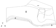
 実施例1と同様のプレス成形品に本実施形態を適用するにあたり、予め、プレス成形における材料流入が多い個所を特定した。図9に従来法でプレス成形した場合のX方向変位量を等高線図で示す。図9において、X方向の正(図9の右方向に向かう)の変位を(+)、負(図9の左方向に向かう)の変位を(-)で表す。この成形後の変位量から材料流入量を評価できる。本部品では、上下左右対称の形状であり、各方向の流入量に差がほとんどないため、全周に本実施形態を適用した。ブランク工程以降は実施例1と同様である。
(Example 2)
In applying this embodiment to a press-formed product similar to that of Example 1, a portion where a large amount of material flows in during press-forming was specified in advance. FIG. 9 is a contour diagram showing the X-direction displacement amount when press molding is performed by the conventional method. In FIG. 9, a positive (toward the right in FIG. 9) displacement in the X direction is represented by (+), and a negative (toward the left in FIG. 9) displacement is represented by (−). The amount of material inflow can be evaluated from the amount of displacement after molding. Since this component has a vertically and horizontally symmetrical shape and there is almost no difference in the inflow amount in each direction, this embodiment is applied to the entire circumference. The steps after the blanking step are the same as in Example 1.
(実施例3)
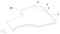
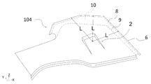
 実施例1と同様のプレス成形品に本実施形態を適用するにあたり、曲げフランジをZ形とし、第1のプレス工程で折り曲げられた平坦縦壁部を、第2のプレス工程において高さ方向に延伸した。図10に第2のプレス成形により、張出成形を施し、中間成形品の中央部に円錐台形状の張出部2を設けたプレス成形品104の斜視図を示す。折り曲げ部6の拘束により、張出成形時の材料流入が抑止され、平板部3には、従来法のようなスプリングバックによるねじれ(図4参照)は見られない。図10に示す平板部代表長さLは、張出部2中央から曲げフランジ6におろした垂線を、平板部3を含む平面に投影したときの長さである。
(Example 3)
In applying this embodiment to a press-formed product similar to that in Example 1, the bending flange is Z-shaped, and the flat vertical wall portion bent in the first pressing step is moved in the height direction in the second pressing step. It was stretched. FIG. 10 is a perspective view of a press-formed product 104 that has been subjected to bulge-forming by the second press-molding and in which a truncated cone-shaped bulged portion 2 is provided in the center of the intermediate-formed product. The restraint of the bent portion 6 suppresses the material inflow at the time of bulging, and the flat plate portion 3 does not show the twist due to the spring back (see FIG. 4) unlike the conventional method. The flat plate portion representative length L shown in FIG. 10 is a length when a perpendicular line drawn from the center of the overhanging portion 2 to the bending flange 6 is projected onto a plane including the flat plate portion 3.
 図11(a)に第1のプレス工程後のZ形折り曲げ部の平坦縦壁部61の状態を示す部分断面模式図を、図11(b)に第2のプレス工程後のZ形折り曲げ部の平坦縦壁部61の状態を示す部分断面模式図を表す。第2のプレス工程において、曲げフランジ部の平坦縦壁部61の、曲げフランジ6に直交する方向の高さh2=3.5mmとして、第1のプレス工程において設計する高さh1=3.0mmより延伸して設計した。その差Δh=0.5mmは、図10に示す平板部代表長さL=150mmの0.33%であった。 FIG. 11A is a schematic partial cross-sectional view showing the state of the flat vertical wall portion 61 of the Z-shaped bent portion after the first pressing step, and FIG. 11B is the Z-shaped bent portion after the second pressing step. The partial cross-sectional schematic diagram which shows the state of the flat vertical wall part 61 of FIG. In the second pressing step, the height h1 of the flat vertical wall portion 61 of the bending flange portion in the direction orthogonal to the bending flange 6 is 3.5 mm, and the height h1 designed in the first pressing step is h1=3.0 mm. Designed by stretching more. The difference Δh=0.5 mm was 0.33% of the flat plate portion representative length L=150 mm shown in FIG.
 その後、トリミング工程にて、図3の矩形形状になるように平板部3をトリミングして、最終製品とする。 After that, in the trimming process, the flat plate portion 3 is trimmed so as to have the rectangular shape shown in FIG. 3 to obtain the final product.
 図12に本実施例におけるプレス成形品のスプリングバック量の一例を等高線で示す。Z軸方向の変位の表記は図7と同じである。矩形平板部3外形線の辺の歪はほとんどなく、Z方向の変位等高線は同心円に近くなっており、ハネ量(+の変位)は最大で0.3mmに収まり、落ち込み量(-の変位)は最大で0.3mmに収まっていた。従来法に比べ、本発明法では、パネルのゆがみが大幅に改善されていることがわかる。 FIG. 12 shows an example of the amount of springback of the press-formed product in this example by contour lines. The notation of displacement in the Z-axis direction is the same as in FIG. 7. Rectangle flat plate part 3 There is almost no distortion on the side of the outline, the displacement contours in the Z direction are close to concentric circles, the amount of splash (+ displacement) is within 0.3 mm at the maximum, and the amount of depression (- displacement) Was within 0.3 mm at maximum. It can be seen that the distortion of the panel is significantly improved in the method of the present invention as compared with the conventional method.
(実施例4)
 次に、実部品のAピラーロアインナーの成形に本実施形態を適用した。概略長さ700mm×幅400mmの部品である。材料は、980MPa級冷間圧延鋼板(ハイテン)で、板厚が1.2mmであり、機械特性は、降伏点(YP)が620MPa、引張強さ(TS)が1030MPa、伸び(El)が15%であった。
(Example 4)
Next, the present embodiment was applied to the molding of the A-pillar lower inner of the actual part. It is a component having an approximate length of 700 mm and a width of 400 mm. The material is 980 MPa cold-rolled steel sheet (Hi-Ten), the plate thickness is 1.2 mm, and the mechanical properties are a yield point (YP) of 620 MPa, a tensile strength (TS) of 1030 MPa, and an elongation (El) of 15. %Met.
 図13にプレス成形品1の形状を斜視図で示す。長手方向右側の幅が大きくなっており、右側の幅中央付近に面直方向への張出部2を持つ。平板部3をXY面とし、長手方向を右側向きにX軸、幅方向を上向きにY軸と置き、平板面に垂直で張出部2が凸の方向をZ軸の正とする座標系とする。以下に、同じ。手前側(Y値の小さい側の辺)に断面Z形のステップ部7を有している。本部品を従来法でプレス成形すると図14に示すようにスプリングバックにより、平板部3がゆがむ。図14では、スプリングバック後のプレス成形品101は、成形下死点のエッジ形状102からZ方向にハネたり(部品の後方)、落ち込んだり(部品の上下)してゆがんでいることがわかる。 Fig. 13 shows a perspective view of the shape of the press-formed product 1. The width on the right side in the longitudinal direction is large, and the protrusion 2 in the direction perpendicular to the plane is provided near the center of the width on the right side. The flat plate portion 3 is an XY plane, the longitudinal direction is the rightward X axis, and the width direction is the upward Y axis. A coordinate system is used in which the direction in which the protrusion 2 is convex to the flat plate surface is the positive Z axis. To do. Same below. The step portion 7 having a Z-shaped cross section is provided on the front side (the side having the smaller Y value). When this component is press-molded by the conventional method, the flat plate portion 3 is distorted due to springback as shown in FIG. In FIG. 14, it can be seen that the press-formed product 101 after springback is distorted from the edge shape 102 at the bottom dead center of the forming process in the Z direction (to the rear of the component) or to be depressed (up and down of the component).
 図15には、本部品に本発明に係るプレス成形法を適用し、第1のプレス工程でZ形の折り曲げ加工(図2の(a))を施した中間成形品103の斜視図を示す。本実施例の部品は張出形状周辺の材料流入が大きいため、図15では、製品右側(X値の大きい側の辺)の直線の外形線9に平行に直辺からなる折り曲げ線8を構成し、部品上部右側(Y値の大きい側の辺でX値が大きい側)の曲線の外形線9に対しては、直辺としての折り曲げ線8を3本の直線で近似して構成している。それぞれの折り曲げ線8の交点(直辺の接続部)では、余肉部を切り欠いている。したがって、製品の輪郭外形線9と折り曲げ線8の間の平板部3には、余肉部10が構成されている。この例では、第1のプレス成形の前に、手前側(Y値の小さい側の辺)に事前にステップ加工を施している。 FIG. 15 is a perspective view of an intermediate molded product 103 obtained by applying the press molding method according to the present invention to this component and performing Z-shaped bending (FIG. 2A) in the first pressing step. .. Since the material of the present embodiment has a large material inflow around the overhanging shape, in FIG. 15, a bending line 8 composed of straight sides is formed in parallel with the straight outline line 9 on the right side of the product (the side on which the X value is large). However, for the contour line 9 on the right side of the upper part of the component (the side on which the Y value is large, the side on which the X value is large), the bending line 8 as the straight side is approximated by three straight lines. There is. At the intersection of the bending lines 8 (the connecting portion on the immediate side), the extra thickness portion is cut out. Therefore, a surplus portion 10 is formed on the flat plate portion 3 between the contour outline 9 of the product and the folding line 8. In this example, step processing is performed in advance on the near side (side having a smaller Y value) before the first press molding.
 図16に第2のプレス成形により、上記中間成形品に張出成形を施したプレス成形品104の斜視図を示す。この後、製品の輪郭外形線9に沿って余肉部10をトリミングすることで、図13に示すプレス成形品1の製品とする。 FIG. 16 shows a perspective view of a press-formed product 104 obtained by subjecting the above intermediate-formed product to bulging by the second press-forming. After that, the excess thickness portion 10 is trimmed along the contour outline 9 of the product to obtain the press-formed product 1 shown in FIG.
 実施例1と同様、従来法によるプレス成形後のスプリングバック量の等高線図を図17に、本発明に係るプレス成形法によるプレス成形後のスプリングバック量の等高線図を図18に示す。いずれも上面図であり、スプリングバック量はZ方向の変位で評価している。Z軸方向の変位の表記は図7と同じである。従来法でのスプリングバック量は、ハネ量(+の変位)の最大で3.8mm、落ち込み量(-の変位)の最大で7.1mmであった。本発明に係るプレス成形法を適用した場合、ハネ量(+の変位)が最大で3.4mm、落ち込み量(-の変位)が最大で3.9mmに改善された。 Similar to Example 1, FIG. 17 shows a contour map of the amount of springback after press molding by the conventional method, and FIG. 18 shows a contour map of the amount of springback after press molding by the press molding method according to the present invention. Both are top views, and the springback amount is evaluated by the displacement in the Z direction. The notation of displacement in the Z-axis direction is the same as in FIG. 7. In the conventional method, the springback amount was 3.8 mm at the maximum for the amount of fluff (displacement of +) and 7.1 mm at the maximum for amount of depression (displacement of −). When the press molding method according to the present invention was applied, the amount of splash (+ displacement) was improved to a maximum of 3.4 mm, and the amount of depression (displacement of −) was improved to a maximum of 3.9 mm.
(実施例5)
 実施例4と同様のプレス成形品に本実施形態を適用するにあたり、予め、プレス成形における材料流入が多い個所を特定した。図19には、本部品を従来法でプレス成形したときのX方向変位量を等高線図で、図20には、同じくY方向変位量を等高線図で示す。それぞれ、正の変位を(+)、負の変位を(-)で示す。部品上部右側(Y値が大きい辺のX値が大きい側)と前方側(X値が大きい辺)の材料流入量が多いため、部品上部右側と前方側に本実施形態を適用し、余肉部を付与した。ブランク工程以降は実施例1と同様である。
(Example 5)
In applying the present embodiment to a press-formed product similar to that in Example 4, a portion where a large amount of material flows in the press-forming was specified in advance. FIG. 19 is a contour diagram showing the X-direction displacement amount when the present component is press-molded by the conventional method, and FIG. 20 is the Y-direction displacement amount similarly. Positive displacement is indicated by (+) and negative displacement is indicated by (-). Since the material inflow amount is large on the right side of the upper part of the component (the side where the X value is large on the side where the Y value is large) and the front side (the side where the X value is large), the present embodiment is applied to the right side and the front side of the upper part of the component, and the surplus Parts are given. The steps after the blanking step are the same as in Example 1.
(実施例6)
 実施例4と同様のプレス成形品に本実施形態を適用するにあたり、曲げフランジをZ形とし、第1のプレス工程で折り曲げられた平坦縦壁部を、第2のプレス工程において高さ方向に延伸した。図21に第2のプレス成形により、上記中間成形品に張出成形を施したプレス成形品104の斜視図を示す。ここで、平板部代表長さLは、張出部2中央からそれぞれ曲げフランジ6におろした垂線を、平板部3を含む平面に投影したときの長さである。実施例3と同様、第2のプレス工程において、曲げフランジ部の平坦縦壁部の、曲げフランジに直交する方向の高さh2=3.5mmとして、第1のプレス工程において設計する高さh1=3.0mmより延伸して設計した。その差Δh=0.5mmは、平板部代表長さL=200~250mmの0.20~0.25%であった。
(Example 6)
In applying this embodiment to a press-formed product similar to that in Example 4, the bending flange is Z-shaped, and the flat vertical wall portion bent in the first pressing step is moved in the height direction in the second pressing step. It was stretched. FIG. 21 shows a perspective view of a press-formed product 104 obtained by subjecting the above-mentioned intermediate-formed product to stretch molding by the second press-forming. Here, the flat plate portion representative length L is the length when the perpendiculars drawn from the center of the overhanging portion 2 to the bending flange 6 are projected onto the plane including the flat plate portion 3. Similar to Example 3, in the second pressing step, the height h1 of the flat vertical wall portion of the bending flange portion in the direction perpendicular to the bending flange is set to h2=3.5 mm, and the height h1 designed in the first pressing step is set. =3.0 mm was drawn and designed. The difference Δh=0.5 mm was 0.20 to 0.25% of the representative length L of the flat plate portion=200 to 250 mm.
 その後、製品の輪郭外形線9に沿って余肉部10をトリミングすることで、図9に示すプレス成形品1の製品とする。 After that, the excess thickness portion 10 is trimmed along the contour outline 9 of the product to obtain the press-formed product 1 shown in FIG.
 実施例1と同様、本発明に係るプレス成形法によるプレス成形後のスプリングバック量の等高線図を図22に示す。図22は上面図であり、スプリングバック量はZ方向の変位で評価している。Z軸方向の変位の表記は図7と同じである。図17に示す従来法でのスプリングバック量は、ハネ量(+の変位)の最大で3.8mm、落ち込み量(-の変位)の最大で7.1mmであった。本発明に係るプレス成形法を適用した場合、ハネ量(+の変位)が最大で3.0mm、落ち込み量(-の変位)が最大で3.2mmに改善された。 Similar to Example 1, FIG. 22 shows a contour map of the amount of springback after press molding by the press molding method according to the present invention. FIG. 22 is a top view, and the springback amount is evaluated by the displacement in the Z direction. The notation of displacement in the Z-axis direction is the same as in FIG. 7. The springback amount in the conventional method shown in FIG. 17 was 3.8 mm at maximum for the amount of fluff (displacement of +) and 7.1 mm at maximum for amount of depression (displacement of −). When the press molding method according to the present invention was applied, the amount of fluff (displacement of +) was improved to 3.0 mm at maximum, and the amount of depression (displacement of −) was improved to 3.2 mm at maximum.
 以上、図示例に基づき説明したが、本発明のプレス成形方法、板状材料のブランク材、プレス成形品の製造方法およびプレス成形品は上記例に限定されるものでなく、特許請求の範囲の記載範囲内で適宜変更し得るものであり、例えば、プレス成形品の形状は、図2や図13に示すもの以外でもよく、曲げフランジ部形状も図5や図15に示すもの以外でもよい。 As mentioned above, although explained based on the illustrated example, the press molding method, the blank material of the plate-shaped material, the manufacturing method of the press molded product and the press molded product of the present invention are not limited to the above examples, and the scope of claims is not limited. The shape of the press-molded product may be other than that shown in FIGS. 2 and 13, and the shape of the bent flange portion may be other than that shown in FIGS. 5 and 15, for example.
 かくして本発明のプレス成形方法、板状材料のブランク材、プレス成形の中間成形品、プレス成形品の製造方法およびプレス成形品によれば、スプリングバックを効率的に抑制することができる。本発明の技術は、プレス成形時の材料流入が成形精度に影響する部品に適用して好適である。 Thus, according to the press-molding method, the blank material of the plate-shaped material, the press-molded intermediate molded product, the press-molded product manufacturing method, and the press-molded product of the present invention, springback can be efficiently suppressed. The technique of the present invention is suitable for application to parts in which material influx during press molding affects molding accuracy.
 1 プレス成形品
 2 張出部
 3 平板部
 4 パンチ底(底面)
 5 縦壁(側壁)
 6 曲げフランジ部
61 平坦縦壁部
 7 ステップ部
 8 折り曲げ線
 9 製品の輪郭外形線
10 余肉部
101 スプリングバック後のプレス成形品
102 成形下死点のエッジ形状
103 曲げ成形後の中間成形品
104 張出成形後のプレス成形品
1 Press-formed product 2 Overhang 3 Flat plate 4 Punch bottom (bottom surface)
5 Vertical wall (side wall)
6 Bending Flange Part 61 Flat Vertical Wall Part 7 Step Part 8 Bending Line 9 Product Outline Outline Line 10 Surplus Part 101 Press Formed Product 102 After Spring Back Molding Bottom Dead Center Edge Shape 103 Intermediate Formed Product 104 After Bending Molding Press-formed products after bulging

Claims (17)

  1.  張出部を有するプレス成形品を板状材料からプレス成形する方法において、
     前記板状材料が余肉部を有し、該余肉部を直辺で折り曲げ、曲げフランジ部を有する中間成形品とする第1のプレス工程と、
     前記中間成形品に前記張出部を設ける張出加工を含むプレス成形を施す第2のプレス工程と、
     を含むことを特徴とするプレス成形方法。
    In the method of press-forming a press-formed product having a bulge from a plate-shaped material,
    A first pressing step in which the plate-shaped material has a surplus portion, and the surplus portion is bent along a straight side to form an intermediate molded product having a bent flange portion;
    A second pressing step of performing press molding including bulging processing for providing the bulged portion on the intermediate molded product;
    A press-molding method comprising:
  2. 前記第1のプレス工程の前に、
    予め特定したプレス成形時の材料流入量に応じて、前記プレス成形品の展開形状の輪郭外形に余肉部を設けるブランク形状を決定するブランク形状の決定工程を有することを特徴とする請求項1に記載のプレス成形方法。
    Before the first pressing step,
    A blank shape determining step of determining a blank shape for providing a surplus portion on the contour outline of the developed shape of the press-formed product according to a pre-specified amount of material inflow at the time of press-forming. The press molding method described in.
  3.  前記曲げフランジ部の断面をL形またはZ形とすることを特徴とする請求項1または2に記載のプレス成形方法。 The press forming method according to claim 1 or 2, wherein the bending flange portion has an L-shaped or Z-shaped cross section.
  4.  前記曲げフランジ部の断面をZ形とし、
     前記第1のプレス工程で折り曲げられた平坦縦壁部を、前記第2のプレス工程において高さ方向に延伸することを特徴とする請求項1または2に記載のプレス成形方法。
    The cross section of the bending flange is Z-shaped,
    The press molding method according to claim 1, wherein the flat vertical wall portion bent in the first pressing step is stretched in the height direction in the second pressing step.
  5.  前記平坦縦壁部の延伸された高さΔhを、対応する曲げフランジ部に接続する平板部の代表長さLの0.2~1.0%とする、ここで、平板部の代表長さLとは、張出部中央から曲げフランジにおろした垂線を、平板部を含む平面に投影したときの長さであることを特徴とする請求項4に記載のプレス成形方法。 The extended height Δh of the flat vertical wall portion is 0.2 to 1.0% of the representative length L of the flat plate portion connected to the corresponding bending flange portion, where the representative length of the flat plate portion is 5. The press forming method according to claim 4, wherein L is a length when a perpendicular line drawn from the center of the overhang portion to the bending flange is projected on a plane including the flat plate portion.
  6.  前記第1のプレス工程では、前記余肉部を、前記プレス成形品の展開形状の輪郭外形線に対し外接、または離隔した直辺で折り曲げることを特徴とする請求項1~5のいずれか1項に記載のプレス成形方法。 6. In the first pressing step, the extra thickness portion is bent at a straight side circumscribing or separated from the contour outline of the developed shape of the press-formed product. The press molding method according to item.
  7.  請求項1~6のいずれか一項に記載のプレス成形方法の余肉部を有する板状材料のブランク材。 A blank material of a plate-like material having a surplus portion of the press molding method according to any one of claims 1 to 6.
  8.  前記余肉部が、隣り合う前記直辺の接続部に切り欠きを有することを特徴とする請求項7に記載の板状材料のブランク材。 The blank material of the plate-shaped material according to claim 7, wherein the extra thickness portion has a notch in a connection portion of the adjacent straight sides.
  9.  請求項1または2に記載のプレス成形方法における前記中間成形品であって、
     余肉部に直辺で折り曲げられた曲げフランジ部を有することを特徴とする中間成形品。
    The intermediate molded article in the press molding method according to claim 1 or 2,
    An intermediate molded product, characterized in that it has a bent flange portion that is bent along the straight side in the extra thickness portion.
  10.  前記曲げフランジ部の断面がL形またはZ形であることを特徴とする請求項9に記載の中間成形品。 The intermediate molded product according to claim 9, wherein the bent flange portion has an L-shaped or Z-shaped cross section.
  11.  張出部を有するプレス成形品を板状材料から製造する方法であって、
     前記プレス成形品の展開形状の外形に余肉部を付して前記板状材料から抜き加工するブランク工程と、
     前記余肉部を直辺で折り曲げ、曲げフランジ部を有する中間成形品とする第1のプレス工程と、
     前記中間成形品に前記張出部を設ける張出加工を含むプレス成形を施す第2のプレス工程と、
     前記余肉部をトリミングするトリミング工程と、
    を含むことを特徴とするプレス成形品の製造方法。
    A method of manufacturing a press-formed product having a bulged portion from a plate-shaped material,
    A blank step of punching from the plate-shaped material by adding a surplus portion to the outer shape of the expanded shape of the press-formed product,
    A first pressing step for bending the extra thickness portion along a straight side to form an intermediate molded product having a bending flange portion;
    A second pressing step of performing press molding including bulging processing for providing the bulged portion on the intermediate molded product;
    A trimming step of trimming the extra thickness portion,
    A method for producing a press-formed product, comprising:
  12. 前記ブランク工程の前に、
    予め特定したプレス成形時の材料流入量に応じて、前記プレス成形品の展開形状の輪郭外形に余肉部を設けるブランク形状を決定するブランク形状の決定工程を有することを特徴とする請求項11に記載のプレス成形品の製造方法。
    Before the blanking step,
    12. A blank shape determining step of determining a blank shape for providing a surplus portion on a contour outer shape of the developed shape of the press-formed product according to a material inflow amount at the time of press-forming specified in advance. The method for producing a press-formed product according to.
  13.  前記曲げフランジ部の断面をL形またはZ形とすることを特徴とする請求項11または12に記載のプレス成形品の製造方法。 The method for manufacturing a press-formed product according to claim 11 or 12, characterized in that the bending flange has a L-shaped or Z-shaped cross section.
  14.  前記曲げフランジ部の断面をZ形とし、
     前記第1のプレス工程で折り曲げられた平坦縦壁部を、前記第2のプレス工程において高さ方向に延伸することを特徴とする請求項11または12に記載のプレス成形品の製造方法。
    The cross section of the bending flange is Z-shaped,
    The method for producing a press-formed product according to claim 11 or 12, wherein the flat vertical wall portion bent in the first pressing step is stretched in the height direction in the second pressing step.
  15.  前記平坦縦壁部の延伸された高さΔhを、対応する曲げフランジ部に接続する平板部の代表長さLの0.2~1.0%とする、ここで、平板部の代表長さLとは、張出部中央から曲げフランジにおろした垂線を、平板部を含む平面に投影したときの長さであることを特徴とする請求項14に記載のプレス成形品の製造方法。 The extended height Δh of the flat vertical wall portion is 0.2 to 1.0% of the representative length L of the flat plate portion connected to the corresponding bending flange portion, where the representative length of the flat plate portion is The method for producing a press-formed product according to claim 14, wherein L is a length when a perpendicular line drawn from the center of the overhanging portion to the bending flange is projected onto a plane including the flat plate portion.
  16.  前記第1のプレス工程では、前記余肉部を、前記プレス成形品の展開形状の輪郭外形線に対し外接、または離隔した直辺で折り曲げることを特徴とする請求項11~15のいずれか1項に記載のプレス成形品の製造方法。 16. In the first pressing step, the extra thickness portion is bent at a straight side circumscribing or separated from the contour outline of the developed shape of the press-formed product. A method for manufacturing a press-formed product according to item.
  17.  請求項1~6のいずれか一項に記載のプレス成形方法でプレス成形されることを特徴とするプレス成形品。 A press-formed product, which is press-formed by the press-forming method according to any one of claims 1 to 6.
PCT/JP2019/048026 2019-01-11 2019-12-09 Press-molding method, blank member of plate-shaped material, intermediate molded article, method for manufacturing press-molded article, and press-molded article WO2020144995A1 (en)

Priority Applications (6)

Application Number Priority Date Filing Date Title
EP19909134.9A EP3909697A4 (en) 2019-01-11 2019-12-09 Press-molding method, blank member of plate-shaped material, intermediate molded article, method for manufacturing press-molded article, and press-molded article
US17/417,217 US20220048088A1 (en) 2019-01-11 2019-12-09 Press-forming method, blank member for sheet-shaped material, intermediate formed product, method for manufacturing press-formed product, and press-formed product
MX2021008365A MX2021008365A (en) 2019-01-11 2019-12-09 Press-molding method, blank member of plate-shaped material, intermediate molded article, method for manufacturing press-molded article, and press-molded article.
CN201980088564.6A CN113286672B (en) 2019-01-11 2019-12-09 Press molding method, blanking of plate-like material, intermediate molded article, method for producing press molded article, and press molded article
KR1020217018986A KR102499437B1 (en) 2019-01-11 2019-12-09 Press-forming method, blank member for sheet-shaped material, intermediate formed product, method for manufacturing press-formed product, and press-formed product
JP2020509118A JP6702521B1 (en) 2019-01-11 2019-12-09 Press molding method, blank material of plate-shaped material, intermediate molded product, method of manufacturing press molded product, and press molded product

Applications Claiming Priority (6)

Application Number Priority Date Filing Date Title
JP2019-003819 2019-01-11
JP2019-003793 2019-01-11
JP2019003793 2019-01-11
JP2019003819 2019-01-11
JP2019160018 2019-09-03
JP2019-160018 2019-09-03

Publications (1)

Publication Number Publication Date
WO2020144995A1 true WO2020144995A1 (en) 2020-07-16

Family

ID=71520722

Family Applications (1)

Application Number Title Priority Date Filing Date
PCT/JP2019/048026 WO2020144995A1 (en) 2019-01-11 2019-12-09 Press-molding method, blank member of plate-shaped material, intermediate molded article, method for manufacturing press-molded article, and press-molded article

Country Status (3)

Country Link
KR (1) KR102499437B1 (en)
CN (1) CN113286672B (en)
WO (1) WO2020144995A1 (en)

Citations (6)

* Cited by examiner, † Cited by third party
Publication number Priority date Publication date Assignee Title
JPS547862B2 (en) * 1974-10-26 1979-04-10
JPH0237248B2 (en) * 1981-12-05 1990-08-23 Toyota Motor Co Ltd
JPH11277155A (en) 1998-03-30 1999-10-12 Topre Corp Flatness straightening method of press formed parts
JP2009255117A (en) 2008-04-15 2009-11-05 Nippon Steel Corp Press-forming method excellent in shape fixability and apparatus therefor
JP2013169578A (en) * 2012-02-22 2013-09-02 Topre Corp Molding method of press component
JP6176430B1 (en) 2016-03-01 2017-08-09 Jfeスチール株式会社 Manufacturing method of press-molded products

Family Cites Families (10)

* Cited by examiner, † Cited by third party
Publication number Priority date Publication date Assignee Title
JPH0751761A (en) * 1993-08-18 1995-02-28 Nkk Corp Production of panel parts by detonation pressure
JP3547862B2 (en) * 1995-09-08 2004-07-28 本田技研工業株式会社 Forming method of draw-formed product having bent flange
US6877349B2 (en) * 2000-08-17 2005-04-12 Industrial Origami, Llc Method for precision bending of sheet of materials, slit sheets fabrication process
CN1954934A (en) * 2005-10-25 2007-05-02 比亚迪股份有限公司 Method for preventing bach after turnup
HUE060567T2 (en) * 2013-05-13 2023-03-28 Nippon Steel Corp Method of manufacturing a worked component
JP5664810B1 (en) * 2013-06-27 2015-02-04 Jfeスチール株式会社 Press forming method and apparatus
WO2016157976A1 (en) * 2015-03-31 2016-10-06 Jfeスチール株式会社 Press molding method, method for manufacturing component in which said press molding method is used, and component manufactured using said press molding method
KR101947943B1 (en) * 2015-06-16 2019-02-13 제이에프이 스틸 가부시키가이샤 Method of manufacturing stretch-flanged component
KR102023541B1 (en) * 2015-08-28 2019-09-20 제이에프이 스틸 가부시키가이샤 Method for manufacturing stretch-flange-formed component
MX369681B (en) * 2016-03-01 2019-11-15 Jfe Steel Corp Method for manufacturing press molded product.

Patent Citations (6)

* Cited by examiner, † Cited by third party
Publication number Priority date Publication date Assignee Title
JPS547862B2 (en) * 1974-10-26 1979-04-10
JPH0237248B2 (en) * 1981-12-05 1990-08-23 Toyota Motor Co Ltd
JPH11277155A (en) 1998-03-30 1999-10-12 Topre Corp Flatness straightening method of press formed parts
JP2009255117A (en) 2008-04-15 2009-11-05 Nippon Steel Corp Press-forming method excellent in shape fixability and apparatus therefor
JP2013169578A (en) * 2012-02-22 2013-09-02 Topre Corp Molding method of press component
JP6176430B1 (en) 2016-03-01 2017-08-09 Jfeスチール株式会社 Manufacturing method of press-molded products

Also Published As

Publication number Publication date
KR20210092295A (en) 2021-07-23
KR102499437B1 (en) 2023-02-13
CN113286672B (en) 2023-04-21
CN113286672A (en) 2021-08-20

Similar Documents

Publication Publication Date Title
TWI448338B (en) Press-forming method of component having l shape
CN109414745B (en) Method and apparatus for manufacturing stamped member
KR100760410B1 (en) Press forming method and press forming device
EP3320996B1 (en) Method and apparatus for manufacturing press component
JP2009241109A (en) Bend-forming method of channel member
JP6631759B1 (en) Press part manufacturing method, press forming apparatus, and metal plate for press forming
KR102023541B1 (en) Method for manufacturing stretch-flange-formed component
KR20160043105A (en) Press molded product, press molded product manufacturing method, and press molded product manufacturing device
JP6702521B1 (en) Press molding method, blank material of plate-shaped material, intermediate molded product, method of manufacturing press molded product, and press molded product
WO2020144995A1 (en) Press-molding method, blank member of plate-shaped material, intermediate molded article, method for manufacturing press-molded article, and press-molded article
JP5079604B2 (en) Metal mold for press forming of cross-section hat-shaped member and press molding method
JPWO2019187863A1 (en) Press-molded product design method, press-molding die, press-molded product, and press-molded product manufacturing method
JP7205520B2 (en) METHOD FOR MANUFACTURING PRESS PARTS AND METAL PLATE FOR PRESS MOLDING
JP7364905B2 (en) Sheet metal molded product manufacturing method, sheet metal molded product manufacturing device, and flange up tool
JP7006666B2 (en) Design method for press-molded products, manufacturing method for press-molded products and press-molded products
JP2021176646A (en) Manufacturing method for press component, metal plate for press molding, and high-tensile steel plate
JP7239048B1 (en) Press molding method and method for manufacturing press molded product
JP7264116B2 (en) Method for evaluating rigidity of press-formed product, method for determining shape, and method for manufacturing press-formed product
JP7188567B2 (en) blanks and parts
WO2017195795A1 (en) Structure and production method therefor
JP2020124726A (en) Press molding item and press work method
JP2023117363A (en) Press-molding method and manufacturing method for press-molded product
KR20170122463A (en) manufacturing method for panel of vehicle using high strength and low specific gravity
JP2024001837A (en) Press forming method and manufacturing method for press-formed product
JP2023177203A (en) Press molding method and method for manufacturing press molded article

Legal Events

Date Code Title Description
ENP Entry into the national phase

Ref document number: 2020509118

Country of ref document: JP

Kind code of ref document: A

121 Ep: the epo has been informed by wipo that ep was designated in this application

Ref document number: 19909134

Country of ref document: EP

Kind code of ref document: A1

ENP Entry into the national phase

Ref document number: 20217018986

Country of ref document: KR

Kind code of ref document: A

NENP Non-entry into the national phase

Ref country code: DE

ENP Entry into the national phase

Ref document number: 2019909134

Country of ref document: EP

Effective date: 20210811