WO2020144967A1 - 制御装置 - Google Patents
制御装置 Download PDFInfo
- Publication number
- WO2020144967A1 WO2020144967A1 PCT/JP2019/046609 JP2019046609W WO2020144967A1 WO 2020144967 A1 WO2020144967 A1 WO 2020144967A1 JP 2019046609 W JP2019046609 W JP 2019046609W WO 2020144967 A1 WO2020144967 A1 WO 2020144967A1
- Authority
- WO
- WIPO (PCT)
- Prior art keywords
- input
- erroneous
- unit
- erroneous input
- user
- Prior art date
- Legal status (The legal status is an assumption and is not a legal conclusion. Google has not performed a legal analysis and makes no representation as to the accuracy of the status listed.)
- Ceased
Links
Images



Classifications
-
- B—PERFORMING OPERATIONS; TRANSPORTING
- B60—VEHICLES IN GENERAL
- B60K—ARRANGEMENT OR MOUNTING OF PROPULSION UNITS OR OF TRANSMISSIONS IN VEHICLES; ARRANGEMENT OR MOUNTING OF PLURAL DIVERSE PRIME-MOVERS IN VEHICLES; AUXILIARY DRIVES FOR VEHICLES; INSTRUMENTATION OR DASHBOARDS FOR VEHICLES; ARRANGEMENTS IN CONNECTION WITH COOLING, AIR INTAKE, GAS EXHAUST OR FUEL SUPPLY OF PROPULSION UNITS IN VEHICLES
- B60K35/00—Instruments specially adapted for vehicles; Arrangement of instruments in or on vehicles
- B60K35/20—Output arrangements, i.e. from vehicle to user, associated with vehicle functions or specially adapted therefor
- B60K35/29—Instruments characterised by the way in which information is handled, e.g. showing information on plural displays or prioritising information according to driving conditions
-
- B—PERFORMING OPERATIONS; TRANSPORTING
- B60—VEHICLES IN GENERAL
- B60R—VEHICLES, VEHICLE FITTINGS, OR VEHICLE PARTS, NOT OTHERWISE PROVIDED FOR
- B60R16/00—Electric or fluid circuits specially adapted for vehicles and not otherwise provided for; Arrangement of elements of electric or fluid circuits specially adapted for vehicles and not otherwise provided for
- B60R16/02—Electric or fluid circuits specially adapted for vehicles and not otherwise provided for; Arrangement of elements of electric or fluid circuits specially adapted for vehicles and not otherwise provided for electric constitutive elements
- B60R16/023—Electric or fluid circuits specially adapted for vehicles and not otherwise provided for; Arrangement of elements of electric or fluid circuits specially adapted for vehicles and not otherwise provided for electric constitutive elements for transmission of signals between vehicle parts or subsystems
- B60R16/027—Electric or fluid circuits specially adapted for vehicles and not otherwise provided for; Arrangement of elements of electric or fluid circuits specially adapted for vehicles and not otherwise provided for electric constitutive elements for transmission of signals between vehicle parts or subsystems between relatively movable parts of the vehicle, e.g. between steering wheel and column
-
- B—PERFORMING OPERATIONS; TRANSPORTING
- B60—VEHICLES IN GENERAL
- B60K—ARRANGEMENT OR MOUNTING OF PROPULSION UNITS OR OF TRANSMISSIONS IN VEHICLES; ARRANGEMENT OR MOUNTING OF PLURAL DIVERSE PRIME-MOVERS IN VEHICLES; AUXILIARY DRIVES FOR VEHICLES; INSTRUMENTATION OR DASHBOARDS FOR VEHICLES; ARRANGEMENTS IN CONNECTION WITH COOLING, AIR INTAKE, GAS EXHAUST OR FUEL SUPPLY OF PROPULSION UNITS IN VEHICLES
- B60K35/00—Instruments specially adapted for vehicles; Arrangement of instruments in or on vehicles
- B60K35/10—Input arrangements, i.e. from user to vehicle, associated with vehicle functions or specially adapted therefor
-
- B—PERFORMING OPERATIONS; TRANSPORTING
- B60—VEHICLES IN GENERAL
- B60K—ARRANGEMENT OR MOUNTING OF PROPULSION UNITS OR OF TRANSMISSIONS IN VEHICLES; ARRANGEMENT OR MOUNTING OF PLURAL DIVERSE PRIME-MOVERS IN VEHICLES; AUXILIARY DRIVES FOR VEHICLES; INSTRUMENTATION OR DASHBOARDS FOR VEHICLES; ARRANGEMENTS IN CONNECTION WITH COOLING, AIR INTAKE, GAS EXHAUST OR FUEL SUPPLY OF PROPULSION UNITS IN VEHICLES
- B60K35/00—Instruments specially adapted for vehicles; Arrangement of instruments in or on vehicles
- B60K35/20—Output arrangements, i.e. from vehicle to user, associated with vehicle functions or specially adapted therefor
- B60K35/21—Output arrangements, i.e. from vehicle to user, associated with vehicle functions or specially adapted therefor using visual output, e.g. blinking lights or matrix displays
- B60K35/23—Head-up displays [HUD]
-
- B—PERFORMING OPERATIONS; TRANSPORTING
- B62—LAND VEHICLES FOR TRAVELLING OTHERWISE THAN ON RAILS
- B62D—MOTOR VEHICLES; TRAILERS
- B62D1/00—Steering controls, i.e. means for initiating a change of direction of the vehicle
- B62D1/02—Steering controls, i.e. means for initiating a change of direction of the vehicle vehicle-mounted
- B62D1/04—Hand wheels
- B62D1/08—Spokes, e.g. resilient
-
- G—PHYSICS
- G06—COMPUTING OR CALCULATING; COUNTING
- G06F—ELECTRIC DIGITAL DATA PROCESSING
- G06F3/00—Input arrangements for transferring data to be processed into a form capable of being handled by the computer; Output arrangements for transferring data from processing unit to output unit, e.g. interface arrangements
- G06F3/01—Input arrangements or combined input and output arrangements for interaction between user and computer
- G06F3/03—Arrangements for converting the position or the displacement of a member into a coded form
- G06F3/041—Digitisers, e.g. for touch screens or touch pads, characterised by the transducing means
- G06F3/0414—Digitisers, e.g. for touch screens or touch pads, characterised by the transducing means using force sensing means to determine a position
-
- G—PHYSICS
- G06—COMPUTING OR CALCULATING; COUNTING
- G06F—ELECTRIC DIGITAL DATA PROCESSING
- G06F3/00—Input arrangements for transferring data to be processed into a form capable of being handled by the computer; Output arrangements for transferring data from processing unit to output unit, e.g. interface arrangements
- G06F3/01—Input arrangements or combined input and output arrangements for interaction between user and computer
- G06F3/03—Arrangements for converting the position or the displacement of a member into a coded form
- G06F3/041—Digitisers, e.g. for touch screens or touch pads, characterised by the transducing means
- G06F3/0416—Control or interface arrangements specially adapted for digitisers
- G06F3/0418—Control or interface arrangements specially adapted for digitisers for error correction or compensation, e.g. based on parallax, calibration or alignment
-
- B—PERFORMING OPERATIONS; TRANSPORTING
- B60—VEHICLES IN GENERAL
- B60K—ARRANGEMENT OR MOUNTING OF PROPULSION UNITS OR OF TRANSMISSIONS IN VEHICLES; ARRANGEMENT OR MOUNTING OF PLURAL DIVERSE PRIME-MOVERS IN VEHICLES; AUXILIARY DRIVES FOR VEHICLES; INSTRUMENTATION OR DASHBOARDS FOR VEHICLES; ARRANGEMENTS IN CONNECTION WITH COOLING, AIR INTAKE, GAS EXHAUST OR FUEL SUPPLY OF PROPULSION UNITS IN VEHICLES
- B60K2360/00—Indexing scheme associated with groups B60K35/00 or B60K37/00 relating to details of instruments or dashboards
- B60K2360/139—Clusters of instrument input devices
-
- B—PERFORMING OPERATIONS; TRANSPORTING
- B60—VEHICLES IN GENERAL
- B60K—ARRANGEMENT OR MOUNTING OF PROPULSION UNITS OR OF TRANSMISSIONS IN VEHICLES; ARRANGEMENT OR MOUNTING OF PLURAL DIVERSE PRIME-MOVERS IN VEHICLES; AUXILIARY DRIVES FOR VEHICLES; INSTRUMENTATION OR DASHBOARDS FOR VEHICLES; ARRANGEMENTS IN CONNECTION WITH COOLING, AIR INTAKE, GAS EXHAUST OR FUEL SUPPLY OF PROPULSION UNITS IN VEHICLES
- B60K2360/00—Indexing scheme associated with groups B60K35/00 or B60K37/00 relating to details of instruments or dashboards
- B60K2360/143—Touch sensitive instrument input devices
- B60K2360/1446—Touch switches
-
- B—PERFORMING OPERATIONS; TRANSPORTING
- B60—VEHICLES IN GENERAL
- B60K—ARRANGEMENT OR MOUNTING OF PROPULSION UNITS OR OF TRANSMISSIONS IN VEHICLES; ARRANGEMENT OR MOUNTING OF PLURAL DIVERSE PRIME-MOVERS IN VEHICLES; AUXILIARY DRIVES FOR VEHICLES; INSTRUMENTATION OR DASHBOARDS FOR VEHICLES; ARRANGEMENTS IN CONNECTION WITH COOLING, AIR INTAKE, GAS EXHAUST OR FUEL SUPPLY OF PROPULSION UNITS IN VEHICLES
- B60K2360/00—Indexing scheme associated with groups B60K35/00 or B60K37/00 relating to details of instruments or dashboards
- B60K2360/18—Information management
- B60K2360/199—Information management for avoiding maloperation
-
- B—PERFORMING OPERATIONS; TRANSPORTING
- B60—VEHICLES IN GENERAL
- B60K—ARRANGEMENT OR MOUNTING OF PROPULSION UNITS OR OF TRANSMISSIONS IN VEHICLES; ARRANGEMENT OR MOUNTING OF PLURAL DIVERSE PRIME-MOVERS IN VEHICLES; AUXILIARY DRIVES FOR VEHICLES; INSTRUMENTATION OR DASHBOARDS FOR VEHICLES; ARRANGEMENTS IN CONNECTION WITH COOLING, AIR INTAKE, GAS EXHAUST OR FUEL SUPPLY OF PROPULSION UNITS IN VEHICLES
- B60K2360/00—Indexing scheme associated with groups B60K35/00 or B60K37/00 relating to details of instruments or dashboards
- B60K2360/77—Instrument locations other than the dashboard
- B60K2360/782—Instrument locations other than the dashboard on the steering wheel
-
- B—PERFORMING OPERATIONS; TRANSPORTING
- B60—VEHICLES IN GENERAL
- B60K—ARRANGEMENT OR MOUNTING OF PROPULSION UNITS OR OF TRANSMISSIONS IN VEHICLES; ARRANGEMENT OR MOUNTING OF PLURAL DIVERSE PRIME-MOVERS IN VEHICLES; AUXILIARY DRIVES FOR VEHICLES; INSTRUMENTATION OR DASHBOARDS FOR VEHICLES; ARRANGEMENTS IN CONNECTION WITH COOLING, AIR INTAKE, GAS EXHAUST OR FUEL SUPPLY OF PROPULSION UNITS IN VEHICLES
- B60K35/00—Instruments specially adapted for vehicles; Arrangement of instruments in or on vehicles
- B60K35/60—Instruments characterised by their location or relative disposition in or on vehicles
-
- B—PERFORMING OPERATIONS; TRANSPORTING
- B62—LAND VEHICLES FOR TRAVELLING OTHERWISE THAN ON RAILS
- B62D—MOTOR VEHICLES; TRAILERS
- B62D1/00—Steering controls, i.e. means for initiating a change of direction of the vehicle
- B62D1/02—Steering controls, i.e. means for initiating a change of direction of the vehicle vehicle-mounted
- B62D1/04—Hand wheels
- B62D1/046—Adaptations on rotatable parts of the steering wheel for accommodation of switches
-
- G—PHYSICS
- G06—COMPUTING OR CALCULATING; COUNTING
- G06F—ELECTRIC DIGITAL DATA PROCESSING
- G06F3/00—Input arrangements for transferring data to be processed into a form capable of being handled by the computer; Output arrangements for transferring data from processing unit to output unit, e.g. interface arrangements
- G06F3/01—Input arrangements or combined input and output arrangements for interaction between user and computer
- G06F3/03—Arrangements for converting the position or the displacement of a member into a coded form
- G06F3/041—Digitisers, e.g. for touch screens or touch pads, characterised by the transducing means
- G06F3/044—Digitisers, e.g. for touch screens or touch pads, characterised by the transducing means by capacitive means
Definitions
- the present invention relates to a control device.
- Patent Document 1 when a steering wheel (controller) of a vehicle is equipped with a touch switch or the like (input unit), when the rotation of the steering wheel is detected, the input to the touch switch or the like is invalidated.
- the technology is disclosed. This prevents erroneous input due to the user's hand unintentionally touching the touch switch when the user turns the handle when turning right or left.
- the present invention has been made in view of the above circumstances, and is a new and improved control capable of more appropriately realizing an input using an input unit mounted on a controller operated by a user.
- an input detection unit that detects an input by the user to an input unit mounted on a controller operated by the user, and whether the input is an erroneous input based on the input.
- An erroneous input determination unit for determining is provided.
- the erroneous input determination unit may determine whether or not the input is an erroneous input based on the range in which the input is detected by the input unit.
- the erroneous input determination unit determines that the input is an erroneous input when the range in which the input is detected by the input unit includes at least a part of the erroneous input detection range provided in the input unit. You may.
- the erroneous input detection range may include at least a part near the edge of the input unit.
- the erroneous input determination unit may determine whether the input is an erroneous input based on the size or shape of the range in which the input is detected by the input unit.
- the erroneous input determination unit may change the method of determining whether or not the input is an erroneous input, based on the status of control by the user using the controller.
- the input unit may include at least one of a touch input and a press input.
- the controller may include a steering wheel of the vehicle, and the input unit may be mounted on a spoke portion of the steering wheel.
- a touch switch 2 in the example of FIG. 1, the left and right spoke parts 150 is provided in a spoke part 150 of a steering wheel 1 (controller) of an automobile.
- the touch switch 2a and the touch switch 2b (hereinafter, simply referred to as "touch switch 2" when they are not distinguished) are mounted, so that the user operates the handle 1 to move to the touch switch 2 with the thumb or the like.
- Various inputs can be performed by touching.
- a head-up display hereinafter referred to as “HUD”
- a multi-information display Multi Information Display, hereinafter referred to as “MID”
- Various information such as a menu screen is displayed, and further, the user selects a menu by touching the touch switch 2 to realize various functions (for example, mirror operation, wiper operation, volume adjustment of audio output, etc.).
- an unintentional touch is referred to as an “erroneous touch”.
- an erroneous touch is made by erroneously touching the left palm on the touch switch 2a mounted on the spoke 150 on the left side of the steering wheel 1. May go.
- an erroneous input due to an erroneous touch on the touch switch 2 may be made in various driving scenes including a left turn. If an erroneous input is made, various information is displayed on the HUD, MID, etc., for example, which makes it difficult for the user to drive the automobile (in some cases, an accident is induced) or feels uncomfortable.
- Patent Document 1 when a steering wheel (controller) of a vehicle is equipped with a touch switch or the like (input unit), when the rotation of the steering wheel is detected, the input to the touch switch or the like is invalidated.
- the technique is disclosed, the technique cannot even perform an intended input when the steering wheel is rotated.
- FIG. 3A is a diagram showing a specific example of the input detection range 3a in the case where an intended input is made by the left thumb.
- FIG. 3B is a diagram showing a specific example of the input detection range 3b when an erroneous input is made by the left palm.
- the input detection range 3b in the case where an erroneous input is made includes the vicinity of the edge of the touch switch 2a (in the example of FIG. 3B, the vicinity of the left edge of the touch switch 2a) and has a larger area.
- the input detection range 3a in the case where the user makes an intended input does not include the vicinity of the edge of the touch switch 2a and has an elliptical shape with a smaller area. (Not necessarily limited to an elliptical shape).
- FIGS. 3A and 3B are merely examples, and the input detection range in the case where an input intended by the user and an erroneous input is performed are not limited to the example in FIG. 3.
- the touch switch 2a is realized by, for example, a capacitance sensor or the like, but the example of FIG. 3 does not consider the shape of the electrode of the capacitance sensor.
- the inventor of the present case has created the present invention in view of the above circumstances.
- the control device according to the present embodiment detects an input by the user to the input unit mounted on the controller operated by the user, and determines whether the input is an erroneous input based on the input. More specifically, the control device according to the present embodiment determines whether or not the input is an erroneous input, based on the range in which the input is detected by the input unit.
- the erroneous input detection range 11 that is a range for detecting an erroneous input is provided at the edge of the touch switch 10 (input unit), and the control device according to the present embodiment is
- the range in which the input is detected by the touch switch 10 includes at least a part of the erroneous input detection range 11, it is determined that the input is an erroneous input.
- the input detection range 3b in the case where an erroneous input is made includes the vicinity of the edge of the touch switch 2a (input unit), and as shown in FIG.
- the “erroneous input detection range 11” may be provided so as to include at least a part near the edge of the touch switch 10 (input unit).
- the erroneous input detection range 11 does not have to include the entire edge of the touch switch 10, and includes a range in which the user's hand (not necessarily limited to the hand) can easily touch when an erroneous input is made. Good.
- the erroneous input detection range 11 does not necessarily have to include the edge of the touch switch 10, and may include a range separated from the edge of the touch switch 10 by a predetermined distance.
- the erroneous input detection range 11 may be illuminated or may be colored differently from other ranges so that the user can appropriately recognize the erroneous input detection range 11.
- the “controller” is not necessarily limited to the steering wheel of a vehicle (especially an automobile), and may be any one that is used to operate some device.
- the controller may be a steering wheel for all vehicles (including a locomotive, a train, a bus, a motorcycle, or the like), a control stick for an aircraft, a steering wheel for a ship, a steering wheel for a simulator (including a driving simulator, etc.), a game, etc.
- the controller is a steering wheel of a vehicle (particularly an automobile) will be described as an example.
- the “input unit” is not necessarily limited to the touch switch 10 and may be any unit that can receive an input from the user. More specifically, the input unit is one that is input by touch (for example, a touch switch, a touch pad, a touch panel, or the like), or one that is input by pressing (for example, a mechanical switch including a two-stage switch, or the like). ) Is included (but is not necessarily limited to these). Further, the position where the input unit is provided in the controller is not particularly limited. Hereinafter, a case where the input unit is mounted on the spoke unit 150 of the handle (controller) will be described as an example.
- the erroneous input detection range 11 is configured by providing a sensor capable of detecting a touch by the user outside the touch switch 10 (not limited to the touch switch 10) (in other words, the erroneous input detection range 11 is touched). It should be noted that when provided outside the switch 10), not only the touch switch 10 but also the sensor is included in the input unit. A case where the erroneous input detection range 11 is formed by providing a sensor capable of detecting a touch by the user outside the touch switch 10 will be described in detail later.
- FIG. 5 is a block diagram showing a configuration example of the control device 100 according to the present embodiment.
- the control device 100 includes a control unit 110, a transmission/reception unit 120, and a storage unit 130.
- the control unit 110 also includes an input detection unit 111, an erroneous input determination unit 112, and a processing unit 113.
- the control unit 110 is configured to control overall processing performed by the control device 100.
- the control unit 110 can control activation and deactivation of each component.
- the control unit 110 can be realized by a processor such as a CPU (Central Processing Unit) or an MCU (Micro Controller Unit), for example.
- the control content of the control unit 110 is not limited to these.
- the input detection unit 111 is configured to detect a user's input to the input unit mounted on the controller operated by the user. For example, when the user touches the touch switch 10 that is the input unit, the input detection unit 111 detects that the touch switch 10 has been touched based on the signal provided from the touch switch 10 and recognizes the touched position. To do.
- the input detection unit 111 provides the erroneous input determination unit 112 with information regarding the detected input (for example, including information regarding the touched position, etc., hereinafter referred to as “input information”).
- the erroneous input determination unit 112 is configured to determine whether or not the input is an erroneous input, based on the input detected by the input detection unit 111. As described above, the erroneous input determination unit 112 determines whether or not the input is an erroneous input, based on the range in which the input is detected by the touch switch 10. For example, the erroneous input determination unit 112 determines that the input is an erroneous input when the range in which the input is detected by the touch switch 10 includes at least a part of the erroneous input detection range 11 provided in the touch switch 10. To do.
- the erroneous input determination unit 112 provides the input information to the processing unit 113 when determining that the input by the user is not an erroneous input.
- the erroneous input determination unit 112 determines that the input by the user is an erroneous input, instead of providing the input information to the processing unit 113, information indicating that the input is an erroneous input (hereinafter, “erroneous input” Information”) is provided to the processing unit 113.
- the processing unit 113 is configured to execute various processes based on input information and erroneous input information. For example, the processing unit 113 generates information for controlling various configurations (hereinafter, referred to as “control information”) based on the input information, and provides the control information to the various configurations so that the HUD and the MID are obtained.
- control information information for controlling various configurations
- Various information such as a menu screen can be displayed, and various functions (for example, mirror operation, wiper operation, volume adjustment of audio output, etc.) can be realized.
- the processing unit 113 can also provide a control information to various components based on the erroneous input information, thereby realizing the output of a warning for prompting the user to make an intended input. Note that if a warning is output each time an erroneous input is made, the user may have difficulty driving the vehicle or may feel discomfort. Therefore, the processing unit 113 appropriately adjusts the warning output. May be. For example, when an erroneous input is made with a frequency of a predetermined value or more, the processing unit 113 may reduce the number of subsequent warnings. Note that the content of the processing implemented by the processing unit 113 is not limited to the above.
- the transmission/reception unit 120 is configured to transmit/receive information to/from an external configuration or device. For example, when the user performs input by touching the touch switch 10, the transmission/reception unit 120 receives a signal related to the input from the touch switch 10 via, for example, an in-vehicle network. In addition, when the processing unit 113 generates control information for controlling various configurations based on the input information, the transmission/reception unit 120 transmits the control information to the various configurations via, for example, an in-vehicle network, and thus the various configurations. To realize the processing by.
- the content of the information transmitted/received by the transmission/reception unit 120 is not limited to the above.
- the method of transmitting/receiving information by the transmitting/receiving unit 120 is not particularly limited. Further, the transmission/reception unit 120 is, for example, a wired or wireless LAN, a Bluetooth (registered trademark) or a communication card for WUSB (Wireless USB), a router for optical communication, a router for ADSL (Asymmetric Digital Subscriber Line), or various communication. It may have a function as a modem for.
- the storage unit 130 is configured to store various types of information.
- the storage unit 130 stores programs and parameters used by the control unit 110 and the transmission/reception unit 120.
- the storage unit 130 may store the processing result of the control unit 110, information provided from the external device by the transmission/reception unit 120, and the like.
- the content of the information stored in the storage unit 130 is not limited to these.
- the storage unit 130 can be realized by, for example, a ROM (Read Only Memory) or a RAM (Random Access Memory).
- control device 100 has been described above.
- the configuration described above with reference to FIG. 5 is merely an example, and the configuration of the control device 100 is not limited to this example.
- the control device 100 may not include a part of the configuration shown in FIG. 5 or may have a configuration not shown in FIG.
- the configuration shown in FIG. 5 may be provided in an external device (not shown), and the control device 100 may realize the functions described above by communicating and cooperating with the external device.
- FIG. 6 is a flowchart showing an example of the processing flow of the control device 100.
- step S1000 the input detection unit 111 detects the input by the user based on the signal provided from the touch switch 10 (input unit).
- step S1004 the erroneous input determination unit 112 determines whether or not the input is an erroneous input, based on the input detected by the input detection unit 111. More specifically, the erroneous input determination unit 112 determines whether or not the input is an erroneous input based on whether or not the range in which the input is detected by the touch switch 10 includes at least a part of the erroneous input detection range 11. Determine whether.
- step S1012 the processing unit 113 provides the control information to various components based on the erroneous input information to prompt the user for the intended input. A warning is output and the series of processing ends. If the input is not an erroneous input (step S1008/No), in step S1016, the processing unit 113 provides various types of processing by providing control information to various components based on the input information, and a series of processing ends. ..
- the processing flow of the control device 100 is not limited to the example shown in FIG.
- each process in the process flow example shown in FIG. 6 may be replaced with another process, each process may be appropriately omitted, or another process may be added.
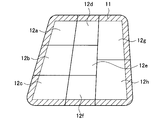
- a mechanical switch group configured by one or more mechanical switches 12 (in the example of FIG. 7, mechanical switches 12a to 12h adjacent to each other) may be used.
- the erroneous input detection range 11 is provided so as to include at least part of the vicinity of the edge in the mechanical switch group.
- the erroneous input detection range 11 is provided so as to include at least part of the vicinity of the edge of the mechanical switch group, and a touch sensor (for example, a capacitance sensor or the like) is provided in the erroneous input detection range 11.
- a touch on the erroneous input detection range 11 may be detected (in this case, the mechanical switch group and the touch sensor constitute an input unit). Then, when the range in which the input is detected includes at least a part of the erroneous input detection range 11, the erroneous input determination unit 112 determines that the input to the mechanical switch group is an erroneous input.
- the input to the erroneous input detection range 11 may be detected by a device other than a touch sensor such as a capacitance sensor.
- a device other than a touch sensor such as a capacitance sensor.
- the input to the erroneous input detection range 11 may be detected based on the signal from the switch. More specifically, when it is detected that the mechanical switch 12 located in the erroneous input detection range 11 has been pressed by the first pressing amount, the erroneous input determination unit 112 causes an erroneous input to the mechanical switch group. May be determined to be
- the mechanical switch group configured by the mechanical switches 12 adjacent to each other has been described as an example.
- the mechanical switches 12 configuring the mechanical switch group may be separated from each other.
- a mechanical switch group including mechanical switches 12i to 12l which are separated from each other may be used.
- the erroneous input detection range 11 may be provided so as to include at least a part of the vicinity of the edge in the mechanical switch group.
- the input units having a mutually discrete form are not limited to the mechanical switch group.
- a touch switch group configured by a plurality of touch switches 10 adjacent to each other may be used.
- the erroneous input detection range 11 does not necessarily have to include the edge of the touch switch 10, and may include the range separated from the edge of the touch switch 10.
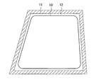
- an erroneous input detection range 11 is provided from the edge of the touch switch 10 across a predetermined area 12 where a touch (input) is not detected, and the erroneous input detection range 11 is provided in the erroneous input detection range 11.
- a touch on the erroneous input detection range 11 may be detected by disposing a capacitance sensor or the like (in this case, the touch switch 10 and the touch sensor form an input unit).
- the erroneous input determination unit 112 has explained that the input is determined to be an erroneous input. 112 does not necessarily need to determine whether the input is an erroneous input based on only the erroneous input detection range 11.
- the erroneous input determination unit 112 may determine whether or not the input is an erroneous input based on the status of control by the user using the controller.
- the erroneous input determination unit 112 may change the method of determining whether the input is an erroneous input depending on the rotation direction of the handle. As described above with reference to FIG. 2, when the user turns the handle 1 to the right at the time of turning right, the touch switch 2a mounted on the spoke portion 150 on the left side of the handle 1 is intended to have the left palm. There is a possibility that erroneous input may be made by touching without touching, but there is a low possibility that the right palm will unintentionally touch the touch switch 2b mounted on the right spoke portion 150 of the handle 1.
- the erroneous input determination unit 112 does not perform the erroneous input determination on the touch switch 10 mounted on the spoke portion 150 on the right side of the steering wheel. Good.
- the erroneous input determination unit 112 does not determine the erroneous input to the touch switch 10 mounted on the spoke portion 150 on the left side of the steering wheel. May be.
- the erroneous input determination unit 112 can appropriately omit unnecessary erroneous input determination processing.
- the erroneous input determination unit 112 may change the method of determining whether or not the input is an erroneous input, based on the position where a body part used for input (for example, the thumb) is detected.
- a body part used for input for example, the thumb
- the body part used for input is based on the detected position can also be said to be "based on the situation of control by the user using the controller").
- the touch sensor for example, a capacitance sensor or the like
- the touch switch 10 detects that the thumb of the user is placed on the thumb rest (where the thumb is placed) on the handle, the user touches the touch switch 10 with the thumb.
- the erroneous input determination unit 112 may determine that an input made during that time is an erroneous input. As a result, the erroneous input determination unit 112 can appropriately detect an erroneous input regardless of the erroneous input detection range 11.
- the body part used for input is not limited to the thumb (that is, the mechanism used for erroneous input determination is not limited to the thumb rest).
- the erroneous input determination unit 112 does not have to make the erroneous input determination. For example, when the user is moving the car backward while looking backwards to park, even if various information is displayed on the HUD, MID, etc. due to an erroneous input, it may be difficult for the user to drive the car ( It is unlikely that an accident will be triggered in some cases) or cause discomfort. Therefore, the erroneous input determination unit 112 makes an erroneous input while the predetermined sensor detects that the user is moving the vehicle backward (or the user is moving the vehicle backward while looking backward).
- the determination unit 112 does not have to make an erroneous input determination. As a result, the erroneous input determination unit 112 can appropriately omit unnecessary erroneous input determination processing.
- the situation in which there is no problem even if an erroneous input is made is not limited to the backward movement of the vehicle.
- the erroneous input determination unit 112 may change the method of determining whether or not the input is an erroneous input, based on the habit of the controller operation by the user. For example, the erroneous input determination unit 112 controls the shape and arrangement of the erroneous input detection range 11 by analyzing the habit of gripping the handle at the time of the current or past handle operation by various sensors, and, for example, is erroneously touched.
- the erroneous input detection range 11 may be set at an easy location, or the erroneous input determination process may be omitted for a user who has a low frequency of erroneous touches.
- a machine learning algorithm, an artificial intelligence algorithm, or the like may be used to analyze the habit of the controller operation by the user.
- the machine learning algorithm or the artificial intelligence algorithm can be generated based on, for example, a machine learning method such as a neural network or a regression model or a statistical method.
- the erroneous input determination unit 112 may determine whether the input is an erroneous input based on the order of input operations by the user. For example, when the user makes an input to the touch switch 10, when the input is started, the user makes an appropriate input without touching the erroneous input detection range 11, and then slides the thumb to touch the erroneous input detection range 11. Suppose In this case, the erroneous input determination unit 112 determines that the input intended by the user is continuing even if the erroneous input detection range 11 is touched, and inputs the erroneous input detection range 11 appropriately. It may be determined that there is. As a result, the area of the touch switch 10 including the erroneous input detection range 11 is used more effectively. When the input unit such as the touch switch 10 is mounted on a controller such as a handle, the input unit is often limited to a smaller size, and thus the above determination method can be said to be more useful.
- the erroneous input determination unit 112 may determine that the input is an appropriate input based on the fact that the input operation indicating that the input operation is intended by the user is separately performed. For example, when the user performs an input by touching the touch switch 10 after performing a flick operation (an operation of sliding a fingertip while touching the touch switch 10), the erroneous input determination unit 112 causes the user to input the input. May be determined to be an appropriate input intended by.
- the erroneous input determination unit 112 may determine whether or not the input is an erroneous input, based on the size or shape of the range in which the input is detected by the input unit. More specifically, as described above with reference to FIG. 3A, when the touch switch 2a is used as the input unit, the input detection range 3a in the case where the user makes an intended input is It is characterized by having an elliptical shape with a small area. Therefore, when the input detection unit 111 recognizes the size or shape of the range in which the input is detected based on the signal provided from the input unit, the erroneous input determination unit 112 determines the size of the range in which the input is detected. Alternatively, it may be determined whether or not the input is an erroneous input, based on whether or not the shape satisfies the above-mentioned characteristic (smaller area oval shape).
- the control device 100 detects an input by the user to the input unit mounted on the controller operated by the user, and the input is erroneous based on the input. Or not. More specifically, the control device 100 according to the present embodiment determines whether or not the input is an erroneous input, based on the range in which the input is detected by the input unit. Thereby, the control device 100 according to the present embodiment can detect an erroneous input more appropriately.
- control device 110 control unit, 111 input detection unit, 112 erroneous input determination unit, 113 processing unit, 120 transmission/reception unit, 130 storage unit, 150 spoke unit, 10 touch switch (input unit), 2a/2b touch switch (input Part), 1 handle (controller)
Landscapes
- Engineering & Computer Science (AREA)
- Mechanical Engineering (AREA)
- General Engineering & Computer Science (AREA)
- Theoretical Computer Science (AREA)
- Chemical & Material Sciences (AREA)
- Combustion & Propulsion (AREA)
- Transportation (AREA)
- Human Computer Interaction (AREA)
- Physics & Mathematics (AREA)
- General Physics & Mathematics (AREA)
- Steering Controls (AREA)
- User Interface Of Digital Computer (AREA)
Abstract
【課題】ユーザにより操作されるコントローラに搭載された入力部を用いた入力をより適切に実現する。 【解決手段】ユーザにより操作されるコントローラに搭載された入力部への前記ユーザによる入力を検出する入力検出部と、前記入力に基づいて、前記入力が誤入力であるか否かを判定する誤入力判定部と、を備える、制御装置が、提供される。
Description
本発明は、制御装置に関する。
近年、各種コントローラを用いた様々な入力方法が提案されている。例えば、以下の特許文献1には、自動車のハンドル(コントローラ)にタッチスイッチ等(入力部)が搭載されている場合において、ハンドルの回転が検出されるとタッチスイッチ等への入力を無効にする技術が開示されている。これによって、右折時又は左折時等にユーザがハンドルを回転させユーザの手が意図せずタッチスイッチに接触することによる誤入力が防止される。
しかし、特許文献1に開示されている技術によっては、ハンドル回転時には、意図した入力さえも行うことができない。
そこで、本発明は、上記事情に鑑みてなされたものであり、ユーザにより操作されるコントローラに搭載された入力部を用いた入力をより適切に実現することが可能な、新規かつ改良された制御装置を提供する。
上記目的を達成するために、ユーザにより操作されるコントローラに搭載された入力部への前記ユーザによる入力を検出する入力検出部と、前記入力に基づいて、前記入力が誤入力であるか否かを判定する誤入力判定部と、を備える、制御装置が、提供される。
また、前記誤入力判定部は、前記入力部において前記入力が検出された範囲に基づいて、前記入力が誤入力であるか否かを判定してもよい。
また、前記誤入力判定部は、前記入力部において前記入力が検出された範囲が、前記入力部において設けられた誤入力検出範囲の少なくとも一部を含む場合、前記入力が誤入力であると判定してもよい。
前記誤入力検出範囲は、前記入力部の縁近傍の少なくとも一部を含んでもよい。
前記誤入力判定部は、前記入力部において前記入力が検出された範囲の大きさ又は形状に基づいて、前記入力が誤入力であるか否かを判定してもよい。
前記誤入力判定部は、前記ユーザによる前記コントローラを用いたコントロールの状況に基づいて、前記入力が誤入力であるか否かの判定方法を変更してもよい。
前記入力部は、タッチによって入力が行われるもの、又は押圧によって入力が行われるもののうちの少なくともいずれか一つを含んでもよい。
前記コントローラは、車両のハンドルを含み、前記入力部は、前記ハンドルのスポーク部に搭載されてもよい。
本発明によれば、ユーザにより操作されるコントローラに搭載された入力部を用いた入力をより適切に実現することができる。
以下、添付図面を参照しながら、本発明の好適な実施の形態について詳細に説明する。なお、本明細書及び図面において、実質的に同一の機能構成を有する構成要素については、同一の符号を付することにより重複説明を省略する。
<1.本発明の一実施形態の概要>
まず、本発明の一実施形態の概要について説明する。
まず、本発明の一実施形態の概要について説明する。
上記のとおり、近年、各種コントローラを用いた様々な入力方法が提案されている。例えば、図1(又は、上記の特許文献1)に示すように、自動車のハンドル1(コントローラ)のスポーク部150等にタッチスイッチ2(図1の例では、左右のスポーク部150に備えられたタッチスイッチ2a及びタッチスイッチ2b。以降、これらを区別しない場合には単に「タッチスイッチ2」と呼称する)が搭載されることで、ユーザは、ハンドル1を操作しながら親指等でタッチスイッチ2へタッチすることによって各種入力を行うことができる。例えば、ユーザがタッチスイッチ2へタッチすることで、ヘッドアップディスプレイ(Head-Up Display。以降「HUD」と呼称する)、やマルチインフォメーションディスプレイ(Multi Information Display。以降、「MID」と呼称する)にメニュー画面等の各種情報を表示させ、さらに、ユーザは、タッチスイッチ2へタッチすることでメニューを選択し、各種機能(例えば、ミラー操作、ワイパー操作、音声出力のボリューム調節等)を実現させることができる。
しかしこの場合、ユーザは、自動車のハンドル1の操作に伴い、意図せずタッチスイッチ2にタッチすることで誤入力を行ってしまう場合がある(以降、意図しないタッチを「誤タッチ」と呼称する)。例えば図2に示すように、ユーザが、右折時にハンドル1を右に回転させた場合、ハンドル1の左側のスポーク部150に搭載されたタッチスイッチ2aに左の手掌を誤タッチすることによって誤入力を行ってしまう場合がある。同様に、左折時等を含む様々な運転シーンでタッチスイッチ2への誤タッチによる誤入力が行われる場合がある。誤入力が行われると、例えばHUDやMID等に各種情報が表示されてしまい、ユーザが自動車を運転しにくくなったり(場合によっては事故が誘発されたり)、不快感を覚えたりする。
また、上記の特許文献1には、自動車のハンドル(コントローラ)にタッチスイッチ等(入力部)が搭載されている場合において、ハンドルの回転が検出されるとタッチスイッチ等への入力を無効にする技術が開示されているが、当該技術によっては、ハンドル回転時には、意図した入力さえも行うことができない。
ここで、図3を参照して、タッチスイッチがハンドルの左側のスポーク部150に搭載された場合において、ユーザによる意図した入力と、誤入力との差異についてより具体的に考察する。図3Aは、左手親指による意図した入力が行われた場合における入力の検出範囲3aの具体例を示す図である。図3Bは、左の手掌による誤入力が行われた場合における入力の検出範囲3bの具体例を示す図である。図3Bに示すように、誤入力が行われた場合における入力の検出範囲3bは、タッチスイッチ2aにおける縁近傍(図3Bの例では、タッチスイッチ2aにおける左側の縁近傍)を含み、より大きな面積を有しているのに対し、ユーザによる意図した入力が行われた場合における入力の検出範囲3aは、図3Aに示すように、タッチスイッチ2aにおける縁近傍を含まず、より小さな面積の楕円形状を有している(必ずしも楕円形状に限定されない)。なお図3A及び図3Bは、あくまで一例であり、ユーザによる意図した入力、及び誤入力が行われた場合における入力の検出範囲は図3の例に限定されない。また、タッチスイッチ2aは例えば静電容量センサ等によって実現されるところ、図3の例では静電容量センサの電極の形状を考慮していない点に留意されたい。
本件の発明者は、上記事情に鑑みて本発明を創作するに至った。本実施形態に係る制御装置は、ユーザにより操作されるコントローラに搭載された入力部へのユーザによる入力を検出し、当該入力に基づいて、当該入力が誤入力であるか否かを判定する。より具体的には、本実施形態に係る制御装置は、入力部において入力が検出された範囲に基づいて、当該入力が誤入力であるか否かを判定する。
例えば、図4に示すように、タッチスイッチ10(入力部)の縁に、誤入力を検出するための範囲である「誤入力検出範囲11」が設けられ、本実施形態に係る制御装置は、タッチスイッチ10において入力が検出された範囲が、誤入力検出範囲11の少なくとも一部を含む場合、当該入力が誤入力であると判定する。上記の図3Bに示したように、誤入力が行われた場合における入力の検出範囲3bは、タッチスイッチ2a(入力部)における縁近傍を含むところ、図4に示すように、タッチスイッチ10(入力部)の縁に誤入力検出範囲11が設けられることで、本実施形態に係る制御装置は、より適切に誤入力を検出することができる。
ここで、「誤入力検出範囲11」は、タッチスイッチ10(入力部)の縁近傍の少なくとも一部を含むように設けられていればよい。例えば、誤入力検出範囲11は、タッチスイッチ10の縁全体を含んでいなくてもよく、誤入力が行われる場合にユーザの手(必ずしも手に限定されない)がタッチしやすい範囲を含んでいればよい。また、誤入力検出範囲11は、必ずしもタッチスイッチ10の縁を含んでいなくてもよく、タッチスイッチ10の縁から所定距離ほど離隔した範囲を含んでもよい。また、ユーザが誤入力検出範囲11を適切に認識できるように、誤入力検出範囲11が光ったり、他の範囲とは異なる色彩が付されたりしてもよい。
また、「コントローラ」は、必ずしも車両(特に自動車)のハンドルに限定されず、何らかの装置の操作に用いられるものであればよい。例えば、コントローラは、車両全般(例えば、機関車、電車、バス、又はバイク等を含む)のハンドル、航空機の操縦桿、船舶のハンドル、シミュレータ(例えば、ドライビングシミュレータ等を含む)のハンドル、ゲームに用いられるコントローラ、又はラジコン(ラジオコントロール)や無人航空機のコントローラ等を含む。以降では、コントローラが車両(特に自動車)のハンドルである場合を一例として説明する。
また、「入力部」は、必ずしもタッチスイッチ10に限定されず、ユーザによる入力を受けることが可能なものであればよい。より具体的には、入力部は、タッチによって入力が行われるもの(例えば、タッチスイッチ、タッチパッド、又はタッチパネル等)、又は押圧によって入力が行われるもの(例えば、2段スイッチを含む機械スイッチ等)のうちの少なくともいずれか一つを含むことを想定している(必ずしもこれらに限定されない)。また、コントローラにおいて入力部が備えられる位置は特に限定されない。以降では、入力部が、ハンドル(コントローラ)のスポーク部150に搭載される場合を一例として説明する。また、ユーザによるタッチを検出可能なセンサがタッチスイッチ10(タッチスイッチ10に限定されない)の外部に備えられることで誤入力検出範囲11が構成される場合(換言すると、誤入力検出範囲11がタッチスイッチ10の外部に設けられる場合)、タッチスイッチ10だけでなく当該センサも入力部に含まれる点に留意されたい。ユーザによるタッチを検出可能なセンサがタッチスイッチ10の外部に備えられることで誤入力検出範囲11が構成される場合については後段にて詳述する。
<2.構成例>
上記では、本発明の一実施形態の概要について説明した。続いて、図5を参照して、本実施形態に係る制御装置100の構成例について説明する。図5は、本実施形態に係る制御装置100の構成例を示すブロック図である。
上記では、本発明の一実施形態の概要について説明した。続いて、図5を参照して、本実施形態に係る制御装置100の構成例について説明する。図5は、本実施形態に係る制御装置100の構成例を示すブロック図である。
図5に示すように、本実施形態に係る制御装置100は、制御部110と、送受信部120と、記憶部130と、を備える。また、制御部110は、入力検出部111と、誤入力判定部112と、処理部113と、を備える。
制御部110は、制御装置100が行う処理全般を統括的に制御する構成である。例えば、制御部110は、各構成の起動や停止を制御することができる。制御部110は、例えば、CPU(Central Processing Unit)や、MCU(Micro Controller Unit)等のプロセッサによって実現され得る。なお、制御部110の制御内容はこれらに限定されない。
入力検出部111は、ユーザにより操作されるコントローラに搭載された入力部へのユーザによる入力を検出する構成である。例えばユーザが、入力部であるタッチスイッチ10をタッチすると、入力検出部111は、タッチスイッチ10から提供される信号に基づいてタッチスイッチ10がタッチされたことを検出し、タッチされた位置を認識する。入力検出部111は、検出した入力に関する情報(例えば、タッチされた位置に関する情報等を含む。以降、「入力情報」と呼称する)を誤入力判定部112に提供する。
誤入力判定部112は、入力検出部111によって検出された入力に基づいて、入力が誤入力であるか否かを判定する構成である。上記のとおり、誤入力判定部112は、タッチスイッチ10において入力が検出された範囲に基づいて、当該入力が誤入力であるか否かを判定する。例えば、誤入力判定部112は、タッチスイッチ10において入力が検出された範囲が、タッチスイッチ10において設けられた誤入力検出範囲11の少なくとも一部を含む場合、当該入力が誤入力であると判定する。誤入力判定部112は、ユーザによる入力が誤入力でないと判定した場合、入力情報を処理部113に提供する。一方、誤入力判定部112は、ユーザによる入力が誤入力であると判定した場合、入力情報を処理部113に提供する代わりに、入力が誤入力であることを示す情報(以降、「誤入力情報」と呼称する)を処理部113に提供する。
処理部113は、入力情報や誤入力情報に基づいて各種処理を実行する構成である。例えば、処理部113は、入力情報に基づいて各種構成を制御するための情報(以降、「制御情報」と呼称する)を生成し、当該制御情報を各種構成に提供することでHUDやMIDにメニュー画面等の各種情報を表示させたり、各種機能(例えば、ミラー操作、ワイパー操作、音声出力のボリューム調節等)を実現したりすることができる。
また、処理部113は、誤入力情報に基づいて制御情報を各種構成に提供することで、ユーザに意図した入力を促すための警告の出力を実現したりすることもできる。なお、誤入力が行われる度に警告が出力されると、ユーザが自動車を運転しにくくなったり、不快感を覚えたりする可能性があるため、処理部113は、警告の出力を適宜調節してもよい。例えば、所定値以上の頻度で誤入力が行われた場合、処理部113は、その後の警告の回数を減らしてもよい。なお、処理部113によって実現される処理の内容は上記に限定されない。
送受信部120は、外部の構成や装置との間で情報の送受信を行う構成である。例えば、ユーザがタッチスイッチ10にタッチすることで入力を行った場合、送受信部120は、例えば車載ネットワークを介してタッチスイッチ10から入力に関する信号を受信する。また、処理部113が入力情報に基づいて各種構成を制御するための制御情報を生成した場合、送受信部120は、例えば車載ネットワークを介して当該制御情報を各種構成へ送信することで、各種構成による処理を実現する。なお、送受信部120によって送受信される情報の内容は上記に限定されない。また、送受信部120による情報の送受信方式は特に限定されない。また送受信部120は、例えば、有線又は無線LAN、Bluetooth(登録商標)、又はWUSB(Wireless USB)用の通信カード、光通信用のルータ、ADSL(Asymmetric Digital Subscriber Line)用のルータ、又は各種通信用のモデムとしての機能を有していてもよい。
記憶部130は、各種情報を記憶する構成である。例えば、記憶部130は、制御部110や送受信部120によって使用されるプログラムやパラメータ等を記憶する。また、記憶部130は、制御部110の処理結果や、送受信部120によって外部装置から提供された情報等を記憶してもよい。なお、記憶部130が記憶する情報の内容はこれらに限定されない。記憶部130は、例えばROM(Read Only Memory)やRAM(Random Access Memory)等によって実現され得る。
以上、制御装置100の構成例について説明した。なお、図5を用いて説明した上記の構成はあくまで一例であり、制御装置100の構成は係る例に限定されない。例えば、制御装置100は、図5に示す構成の一部を備えていなくてもよいし、図5に示していない構成を備えていてもよい。また、図5に示す構成が外部装置(図示なし)に設けられ、制御装置100は当該外部装置と通信連携することによって上記で説明した各機能を実現してもよい。
<3.処理フロー例>
上記では、本実施形態に係る制御装置100の構成例について説明した。続いて、図6を参照して、制御装置100の処理フロー例について説明する。図6は、制御装置100の処理フロー例を示すフローチャートである。
上記では、本実施形態に係る制御装置100の構成例について説明した。続いて、図6を参照して、制御装置100の処理フロー例について説明する。図6は、制御装置100の処理フロー例を示すフローチャートである。
ステップS1000では、入力検出部111が、タッチスイッチ10(入力部)から提供される信号に基づいてユーザによる入力を検出する。ステップS1004では、誤入力判定部112が入力検出部111によって検出された入力に基づいて、入力が誤入力であるか否かを判定する。より具体的には、誤入力判定部112は、タッチスイッチ10において入力が検出された範囲が誤入力検出範囲11の少なくとも一部を含むか否かに基づいて当該入力が誤入力であるか否かを判定する。
入力が誤入力である場合(ステップS1008/Yes)、ステップS1012にて、処理部113が、誤入力情報に基づいて制御情報を各種構成に提供することで、ユーザに意図した入力を促すために警告を出力させ、一連の処理が終了する。入力が誤入力でない場合(ステップS1008/No)、ステップS1016にて、処理部113が、入力情報に基づいて制御情報を各種構成に提供することで各種処理を実現し、一連の処理が終了する。
ユーザがタッチスイッチ10(入力部)へ入力を行う度に、図6に示す処理が繰り返し行われる。なお、制御装置100の処理フローは、図6に示した例に限定されない。例えば、図6に示した処理フロー例における各処理は他の処理に置き換えられてもよいし、各処理は適宜省略されてもよいし、他の処理が追加されてもよい。
<4.変形例>
上記では、制御装置100の処理フロー例について説明した。続いて、本実施形態に係る変形例について説明する。
上記では、制御装置100の処理フロー例について説明した。続いて、本実施形態に係る変形例について説明する。
(4.1.入力部と誤入力検出範囲の変形例)
まず、入力部と誤入力検出範囲11の変形例について説明する。上記では、入力部がタッチスイッチ10である場合を主として説明したが、入力部はタッチスイッチ10に限定されない。
まず、入力部と誤入力検出範囲11の変形例について説明する。上記では、入力部がタッチスイッチ10である場合を主として説明したが、入力部はタッチスイッチ10に限定されない。
例えば図7に示すように、1又は2以上の機械スイッチ12(図7の例では、互いに隣接する機械スイッチ12a~機械スイッチ12h)によって構成される機械スイッチ群が用いられてもよい。機械スイッチ群が用いられる場合も、機械スイッチ群における縁近傍の少なくとも一部を含むように誤入力検出範囲11が設けられる。例えば、図7に示すように、機械スイッチ群における縁近傍の少なくとも一部を含むように誤入力検出範囲11が設けられ、当該誤入力検出範囲11にタッチセンサ(例えば静電容量センサ等)が配置されることで、誤入力検出範囲11へのタッチが検出されてもよい(この場合、機械スイッチ群及びタッチセンサによって入力部が構成されることになる)。そして、入力が検出された範囲が誤入力検出範囲11の少なくとも一部を含む場合、誤入力判定部112は、機械スイッチ群への入力が誤入力であると判定する。
なお、機械スイッチ群が用いられる場合において、静電容量センサ等のタッチセンサ以外により誤入力検出範囲11への入力が検出されてもよい。例えば、機械スイッチ群における各機械スイッチ12が、第1の押し込み量と、第1の押し込み量よりも大きい第2の押し込み量とで異なる入力を可能にする2段スイッチである場合、当該2段スイッチからの信号に基づいて誤入力検出範囲11への入力が検出されてもよい。より具体的には、誤入力検出範囲11に位置する機械スイッチ12が第1の押し込み量で押し込まれたことが検出された場合、誤入力判定部112は、機械スイッチ群への入力が誤入力であると判定してもよい。
図7では、互いに隣接する機械スイッチ12によって構成される機械スイッチ群を一例として説明したところ、機械スイッチ群を構成する各機械スイッチ12は、互いに離散していてもよい。例えば図8に示すように、互いに離散した機械スイッチ12i~機械スイッチ12lによって構成される機械スイッチ群が用いられてもよい。この場合においても、図8に示すように、機械スイッチ群における縁近傍の少なくとも一部を含むように誤入力検出範囲11が設けられ得る。なお、互いに離散した態様を有する入力部は、機械スイッチ群に限定されない。例えば、互いに隣接した複数のタッチスイッチ10によって構成されるタッチスイッチ群が用いられてもよい。
また上記のとおり、誤入力検出範囲11は、必ずしもタッチスイッチ10の縁を含んでいなくてもよく、タッチスイッチ10の縁から離隔した範囲を含んでもよい。例えば図9に示すように、タッチスイッチ10の縁から、タッチ(入力)が検出されない所定の領域12を挟んで誤入力検出範囲11が設けられ、当該誤入力検出範囲11にタッチセンサ(例えば静電容量センサ等)が配置されることで、誤入力検出範囲11へのタッチが検出されてもよい(この場合、タッチスイッチ10及びタッチセンサによって入力部が構成されることになる)。
(4.2.誤入力判定方法の変形例)
続いて、誤入力判定方法の変形例について説明する。
続いて、誤入力判定方法の変形例について説明する。
上記では、入力が検出された範囲が誤入力検出範囲11の少なくとも一部を含む場合、誤入力判定部112は、当該入力が誤入力であると判定する旨について説明したところ、誤入力判定部112は、必ずしも誤入力検出範囲11のみに基づいて入力が誤入力であるか否かを判定しなくてもよい。
一例として、誤入力判定部112は、ユーザによるコントローラを用いたコントロールの状況に基づいて入力が誤入力であるか否かを判定してもよい。
例えば、誤入力判定部112は、ハンドルの回転方向によって入力が誤入力であるか否かの判定方法を変えてもよい。上記で図2を参照して説明したように、右折時にユーザがハンドル1を右に回転させた場合、ハンドル1の左側のスポーク部150に搭載されたタッチスイッチ2aに、左の手掌が意図せず触れることによって誤入力が行われる可能性があるところ、ハンドル1の右側のスポーク部150に搭載されたタッチスイッチ2bには右の手掌が意図せず触れる可能性は低い。そこで、右折時にユーザがハンドルを右に回転させたことが検出された場合、誤入力判定部112は、ハンドルの右側のスポーク部150に搭載されたタッチスイッチ10への誤入力判定を行わなくてもよい。逆に、左折時にユーザがハンドルを左に回転させたことが検出された場合、誤入力判定部112は、ハンドルの左側のスポーク部150に搭載されたタッチスイッチ10への誤入力判定を行わなくてもよい。これによって、誤入力判定部112は、不要な誤入力判定処理を適切に省略することができる。
また、誤入力判定部112は、入力に用いられる体の部位(例えば、親指等)が検出された位置に基づいて、入力が誤入力であるか否かの判定方法を変えてもよい(なお、入力に用いられる体の部位が検出された位置に基づくことも、「ユーザによるコントローラを用いたコントロールの状況に基づく」と言える点に留意されたい)。例えば、ハンドルにおけるサムレスト(親指が置かれる箇所)にユーザの親指が置かれていることがタッチセンサ(例えば静電容量センサ等)により検出されている間においては、ユーザは、親指でタッチスイッチ10等をタッチすることができないため、誤入力判定部112は、その間に行われた入力を誤入力と判定してもよい。これによって誤入力判定部112は、誤入力検出範囲11によらずに適切に誤入力を検出することができる。なお、入力に用いられる体の部位は親指に限定されない(すなわち、誤入力判定に用いられる機構もサムレストに限定されない)。
また、誤入力が行われたとしてもコントロールの状況に基づいて問題が無いと考えられる場合、誤入力判定部112は、誤入力判定を行わなくてもよい。例えば、ユーザが駐車するために後方を見ながら自動車を後進させている場合、仮に誤入力が行われHUDやMID等に各種情報が表示されたとしても、ユーザが自動車を運転しにくくなったり(場合によっては事故が誘発されたり)、不快感を覚えたりする可能性は低い。そこで、誤入力判定部112は、ユーザが自動車を後進させていること(又は、ユーザが後方を見ながら自動車を後進させていること)が所定のセンサにより検出されている間においては、誤入力判定部112は誤入力判定を行わなくてもよい。これによって、誤入力判定部112は、不要な誤入力判定処理を適切に省略することができる。なお、誤入力が行われたとしても問題が無いと考えられる状況は自動車の後進時に限定されない。
また、誤入力判定部112は、ユーザによるコントローラ操作の癖に基づいて入力が誤入力であるか否かの判定方法を変えてもよい。例えば、現在又は過去のハンドル操作時におけるハンドルの握り方の癖が各種センサにより解析されることで、誤入力判定部112は、誤入力検出範囲11の形状や配置を制御し、例えば誤タッチされ易い個所に誤入力検出範囲11を設定したり、誤タッチする頻度の低いユーザに対しては誤入力判定処理を省略したりしてもよい。なお、ユーザによるコントローラ操作の癖の解析には、機械学習アルゴリズム又は人工知能アルゴリズム等が用いられてもよい。ここで、機械学習アルゴリズム又は人工知能アルゴリズムは、例えば、ニューラルネットワーク、回帰モデル等の機械学習手法又は統計的手法等に基づいて生成され得る。
また、誤入力判定部112は、ユーザによる入力操作の順に基づいて入力が誤入力であるか否かを判定してもよい。例えば、タッチスイッチ10に対してユーザが入力を行う場合において、入力開始時にはユーザが誤入力検出範囲11をタッチすることなく適切に入力を行い、その後親指をスライドさせて誤入力検出範囲11にタッチしたとする。この場合、誤入力判定部112は、誤入力検出範囲11がタッチされていたとしても、ユーザによる意図した入力が継続していると判断し、誤入力検出範囲11への入力を適切な入力であると判定してもよい。これによって、誤入力検出範囲11を含めてタッチスイッチ10の領域がより有効に活用される。タッチスイッチ10等の入力部がハンドル等のコントローラに搭載される場合、入力部がより小さく制限されることが多いため、上記の判定方法はより有用であると言える。
また、誤入力判定部112は、入力操作がユーザの意図したものであることを示す入力操作が別途行われたことに基づいて、入力が適切な入力であると判定してもよい。例えば、ユーザがフリック操作(指先をタッチスイッチ10に接触させたままスライドさせる操作)を行った後にタッチスイッチ10をタッチすることで入力を行った場合、誤入力判定部112は、当該入力をユーザの意図する適切な入力であると判定してもよい。
また、誤入力判定部112は、入力部において入力が検出された範囲の大きさ又は形状に基づいて、入力が誤入力であるか否かを判定してもよい。より具体的に説明すると、上記で図3Aを参照して説明したとおり、タッチスイッチ2aが入力部として用いられた場合、ユーザによる意図した入力が行われた場合における入力の検出範囲3aは、より小さな面積の楕円形状を有するという特徴がある。そこで、入力検出部111が入力部から提供される信号に基づいて入力が検出された範囲の大きさ又は形状を認識した場合、誤入力判定部112は、当該入力が検出された範囲の大きさ又は形状が、上記の特徴(より小さな面積)の楕円形状)を満たすか否かに基づいて当該入力が誤入力であるか否かを判定してもよい。
<5.むすび>
以上で説明してきたように、本実施形態に係る制御装置100は、ユーザにより操作されるコントローラに搭載された入力部へのユーザによる入力を検出し、当該入力に基づいて、当該入力が誤入力であるか否かを判定する。より具体的には、本実施形態に係る制御装置100は、入力部において入力が検出された範囲に基づいて、当該入力が誤入力であるか否かを判定する。これによって、本実施形態に係る制御装置100は、より適切に誤入力を検出することができる。
以上で説明してきたように、本実施形態に係る制御装置100は、ユーザにより操作されるコントローラに搭載された入力部へのユーザによる入力を検出し、当該入力に基づいて、当該入力が誤入力であるか否かを判定する。より具体的には、本実施形態に係る制御装置100は、入力部において入力が検出された範囲に基づいて、当該入力が誤入力であるか否かを判定する。これによって、本実施形態に係る制御装置100は、より適切に誤入力を検出することができる。
以上、添付図面を参照しながら本発明の好適な実施形態について説明したが、本発明は係る例に限定されないことは言うまでもない。当業者であれば、請求の範囲に記載された範疇内において、各種の変更例又は修正例に想到し得ることは明らかであり、それらについても当然に本発明の技術的範囲に属するものと了解される。
100 制御装置、110 制御部、111 入力検出部、112 誤入力判定部、113 処理部、120 送受信部、130 記憶部、150 スポーク部、10 タッチスイッチ(入力部)、2a・2b タッチスイッチ(入力部)、1 ハンドル(コントローラ)
Claims (8)
- ユーザにより操作されるコントローラに搭載された入力部への前記ユーザによる入力を検出する入力検出部と、
前記入力に基づいて、前記入力が誤入力であるか否かを判定する誤入力判定部と、を備える、
制御装置。 - 前記誤入力判定部は、前記入力部において前記入力が検出された範囲に基づいて、前記入力が誤入力であるか否かを判定する、
請求項1に記載の制御装置。 - 前記誤入力判定部は、前記入力部において前記入力が検出された範囲が、前記入力部において設けられた誤入力検出範囲の少なくとも一部を含む場合、前記入力が誤入力であると判定する、
請求項2に記載の制御装置。 - 前記誤入力検出範囲は、前記入力部の縁近傍の少なくとも一部を含む、
請求項3に記載の制御装置。 - 前記誤入力判定部は、前記入力部において前記入力が検出された範囲の大きさ又は形状に基づいて、前記入力が誤入力であるか否かを判定する、
請求項2に記載の制御装置。 - 前記誤入力判定部は、前記ユーザによる前記コントローラを用いたコントロールの状況に基づいて、前記入力が誤入力であるか否かの判定方法を変更する、
請求項1から5のいずれか1項に記載の制御装置。 - 前記入力部は、タッチによって入力が行われるもの、又は押圧によって入力が行われるもののうちの少なくともいずれか一つを含む、
請求項1から6のいずれか1項に記載の制御装置。 - 前記コントローラは、車両のハンドルを含み、
前記入力部は、前記ハンドルのスポーク部に搭載される、
請求項1から7のいずれか1項に記載の制御装置。
Priority Applications (1)
| Application Number | Priority Date | Filing Date | Title |
|---|---|---|---|
| US17/419,959 US11897402B2 (en) | 2019-01-09 | 2019-11-28 | Control device |
Applications Claiming Priority (2)
| Application Number | Priority Date | Filing Date | Title |
|---|---|---|---|
| JP2019-001650 | 2019-01-09 | ||
| JP2019001650A JP7329328B2 (ja) | 2019-01-09 | 2019-01-09 | 制御装置 |
Publications (1)
| Publication Number | Publication Date |
|---|---|
| WO2020144967A1 true WO2020144967A1 (ja) | 2020-07-16 |
Family
ID=71520755
Family Applications (1)
| Application Number | Title | Priority Date | Filing Date |
|---|---|---|---|
| PCT/JP2019/046609 Ceased WO2020144967A1 (ja) | 2019-01-09 | 2019-11-28 | 制御装置 |
Country Status (3)
| Country | Link |
|---|---|
| US (1) | US11897402B2 (ja) |
| JP (1) | JP7329328B2 (ja) |
| WO (1) | WO2020144967A1 (ja) |
Cited By (1)
| Publication number | Priority date | Publication date | Assignee | Title |
|---|---|---|---|---|
| EP4316947A4 (en) * | 2021-03-29 | 2025-05-07 | Autoliv Development AB | GRIP DETERMINATION SYSTEM AND GRIP DETERMINATION METHOD |
Families Citing this family (2)
| Publication number | Priority date | Publication date | Assignee | Title |
|---|---|---|---|---|
| JP7222960B2 (ja) | 2020-10-27 | 2023-02-15 | 株式会社ホンダアクセス | タッチパネル装置 |
| WO2025008654A1 (ja) * | 2023-07-03 | 2025-01-09 | 日産自動車株式会社 | タッチ操作検知装置 |
Citations (3)
| Publication number | Priority date | Publication date | Assignee | Title |
|---|---|---|---|---|
| JP2013075652A (ja) * | 2011-09-14 | 2013-04-25 | Jvc Kenwood Corp | 車両における操作対象装置の制御装置及び制御方法 |
| JP2016167241A (ja) * | 2015-03-10 | 2016-09-15 | レノボ・シンガポール・プライベート・リミテッド | 携帯型情報処理装置、その磁気ディスク装置保護方法、及びコンピュータが実行可能なプログラム |
| JP2017095066A (ja) * | 2015-11-27 | 2017-06-01 | 京セラ株式会社 | 車両及び車両における制御方法 |
Family Cites Families (6)
| Publication number | Priority date | Publication date | Assignee | Title |
|---|---|---|---|---|
| JP3930288B2 (ja) | 2001-10-30 | 2007-06-13 | 株式会社東海理化電機製作所 | 車載装置制御システム |
| JP5790579B2 (ja) * | 2011-09-15 | 2015-10-07 | 株式会社Jvcケンウッド | 車両における操作対象装置の制御装置及び制御方法 |
| JP2012194997A (ja) * | 2012-07-02 | 2012-10-11 | Canon Inc | 表示制御装置、その制御方法、およびプログラム、並びに記録媒体 |
| JP2014172413A (ja) | 2013-03-06 | 2014-09-22 | Aisin Aw Co Ltd | 操作支援システム、操作支援方法及びコンピュータプログラム |
| US9971407B2 (en) * | 2015-09-30 | 2018-05-15 | Apple Inc. | Haptic feedback for rotary inputs |
| JP6818417B2 (ja) * | 2016-02-22 | 2021-01-20 | キヤノン株式会社 | 表示装置、表示装置の制御方法、及びプログラム |
-
2019
- 2019-01-09 JP JP2019001650A patent/JP7329328B2/ja active Active
- 2019-11-28 US US17/419,959 patent/US11897402B2/en active Active
- 2019-11-28 WO PCT/JP2019/046609 patent/WO2020144967A1/ja not_active Ceased
Patent Citations (3)
| Publication number | Priority date | Publication date | Assignee | Title |
|---|---|---|---|---|
| JP2013075652A (ja) * | 2011-09-14 | 2013-04-25 | Jvc Kenwood Corp | 車両における操作対象装置の制御装置及び制御方法 |
| JP2016167241A (ja) * | 2015-03-10 | 2016-09-15 | レノボ・シンガポール・プライベート・リミテッド | 携帯型情報処理装置、その磁気ディスク装置保護方法、及びコンピュータが実行可能なプログラム |
| JP2017095066A (ja) * | 2015-11-27 | 2017-06-01 | 京セラ株式会社 | 車両及び車両における制御方法 |
Cited By (1)
| Publication number | Priority date | Publication date | Assignee | Title |
|---|---|---|---|---|
| EP4316947A4 (en) * | 2021-03-29 | 2025-05-07 | Autoliv Development AB | GRIP DETERMINATION SYSTEM AND GRIP DETERMINATION METHOD |
Also Published As
| Publication number | Publication date |
|---|---|
| JP7329328B2 (ja) | 2023-08-18 |
| JP2020112906A (ja) | 2020-07-27 |
| US11897402B2 (en) | 2024-02-13 |
| US20220063524A1 (en) | 2022-03-03 |
Similar Documents
| Publication | Publication Date | Title |
|---|---|---|
| US9809231B2 (en) | System and method for executing gesture based control of a vehicle system | |
| JP5948711B2 (ja) | 触覚制御用可変形パッド | |
| US8155837B2 (en) | Operating device on vehicle's steering wheel | |
| CN110709273B (zh) | 用于运行机动车的显示装置的方法、操作装置和机动车 | |
| CN107074170B (zh) | 利用现有车辆用户界面的可训练收发器和操作方法 | |
| JP2007106353A (ja) | 車両用情報表示装置及び車両用情報表示システム | |
| JP7329328B2 (ja) | 制御装置 | |
| CN107206947A (zh) | 车载设备操作装置及车载设备操作系统 | |
| JP2014061761A (ja) | 車載機器操作装置 | |
| WO2016051440A1 (ja) | 車両及びステアリングユニット | |
| JP2014153986A (ja) | 表示装置、および、表示方法 | |
| JP6233248B2 (ja) | 把持状態判定装置、把持状態判定方法、入力装置、入力取得方法 | |
| CN110049892A (zh) | 用于机动车辆的信息娱乐系统的操作装置、用于获知这种操作元件的操作者的所在处的方法 | |
| JP6881368B2 (ja) | 車両用入力装置 | |
| CN108216087B (zh) | 利用对把手式门抓握方式的辨识识别用户的方法和装置 | |
| JP2017030746A (ja) | 車両及びステアリングユニット | |
| JP5761076B2 (ja) | タッチ式スイッチ装置 | |
| CN107054443A (zh) | 一种驾驶控制装置及交通工具、驾驶控制方法 | |
| CN107107762B (zh) | 用于通过为操作元件提供两个操作模式来驱动机动车辆的操作装置的方法,操作装置及机动车辆 | |
| KR101922454B1 (ko) | 전하량 변화를 이용한 제스처 인식 시스템 및 방법 | |
| CN116774822A (zh) | 一种用于车辆的指纹操作系统 | |
| KR102910412B1 (ko) | 주행모드 전환 장치 및 그 방법 | |
| JP7765374B2 (ja) | 操舵装置、制御装置、およびコンピュータプログラム | |
| US20240025254A1 (en) | Display control device for vehicle, display method for vehicle, and non-transitory recording medium for vehicle | |
| JP7192413B2 (ja) | 車両用操作装置 |
Legal Events
| Date | Code | Title | Description |
|---|---|---|---|
| 121 | Ep: the epo has been informed by wipo that ep was designated in this application |
Ref document number: 19908464 Country of ref document: EP Kind code of ref document: A1 |
|
| NENP | Non-entry into the national phase |
Ref country code: DE |
|
| 122 | Ep: pct application non-entry in european phase |
Ref document number: 19908464 Country of ref document: EP Kind code of ref document: A1 |