WO2020140170A1 - 连接器组件以及母连接器 - Google Patents
连接器组件以及母连接器 Download PDFInfo
- Publication number
- WO2020140170A1 WO2020140170A1 PCT/CN2018/125935 CN2018125935W WO2020140170A1 WO 2020140170 A1 WO2020140170 A1 WO 2020140170A1 CN 2018125935 W CN2018125935 W CN 2018125935W WO 2020140170 A1 WO2020140170 A1 WO 2020140170A1
- Authority
- WO
- WIPO (PCT)
- Prior art keywords
- protective cover
- connector
- female connector
- connection terminal
- contact portion
- Prior art date
- Legal status (The legal status is an assumption and is not a legal conclusion. Google has not performed a legal analysis and makes no representation as to the accuracy of the status listed.)
- Ceased
Links
Images
Classifications
-
- H—ELECTRICITY
- H01—ELECTRIC ELEMENTS
- H01R—ELECTRICALLY-CONDUCTIVE CONNECTIONS; STRUCTURAL ASSOCIATIONS OF A PLURALITY OF MUTUALLY-INSULATED ELECTRICAL CONNECTING ELEMENTS; COUPLING DEVICES; CURRENT COLLECTORS
- H01R13/00—Details of coupling devices of the kinds covered by groups H01R12/70 or H01R24/00 - H01R33/00
- H01R13/46—Bases; Cases
- H01R13/50—Bases; Cases formed as an integral body
-
- H—ELECTRICITY
- H01—ELECTRIC ELEMENTS
- H01R—ELECTRICALLY-CONDUCTIVE CONNECTIONS; STRUCTURAL ASSOCIATIONS OF A PLURALITY OF MUTUALLY-INSULATED ELECTRICAL CONNECTING ELEMENTS; COUPLING DEVICES; CURRENT COLLECTORS
- H01R13/00—Details of coupling devices of the kinds covered by groups H01R12/70 or H01R24/00 - H01R33/00
- H01R13/648—Protective earth or shield arrangements on coupling devices, e.g. anti-static shielding
-
- H—ELECTRICITY
- H01—ELECTRIC ELEMENTS
- H01R—ELECTRICALLY-CONDUCTIVE CONNECTIONS; STRUCTURAL ASSOCIATIONS OF A PLURALITY OF MUTUALLY-INSULATED ELECTRICAL CONNECTING ELEMENTS; COUPLING DEVICES; CURRENT COLLECTORS
- H01R13/00—Details of coupling devices of the kinds covered by groups H01R12/70 or H01R24/00 - H01R33/00
- H01R13/648—Protective earth or shield arrangements on coupling devices, e.g. anti-static shielding
- H01R13/658—High frequency shielding arrangements, e.g. against EMI [Electro-Magnetic Interference] or EMP [Electro-Magnetic Pulse]
- H01R13/6581—Shield structure
Definitions
- the invention relates to a connector assembly and a connector, and in particular to a connector assembly and a female connector used for transmission of high-frequency signals.
- the prior art board-to-board connectors have been widely used in many electronic products to connect different functional modules. They provide design, manufacturing and service flexibility for many products.
- RF board-to-board connectors are used to connect RF modules to other functional circuits. Due to the higher operating frequency range and sensitivity to interference from other signals, there are specific considerations in this connector design, such as size and shielding.
- One of the objects of the present invention is to provide a connector assembly that can solve the risk of damage to the connector due to misoperation.
- the second object of the present invention is to provide a female connector, which can solve the risk of damage to the connector due to misoperation.
- a connector assembly includes a male connector and a female connector.
- the male connector includes: a plurality of first connection terminals each having a first contact portion and a first protective cover connected to a ground potential; the female connection
- the connector includes: a plurality of second connection terminals each having a second contact portion and a second protective cover connected to a ground potential. If the male connector is combined with the female connector, the plurality of first connection terminals are The plurality of second connection terminals are respectively in contact with the second contact portion at the first contact portion, and the first protective cover and the second protective cover are in contact with each other; the first protective cover includes A closed ring structure surrounding the first connection terminal, the second protective cover includes a closed ring structure surrounding the second connection terminal.
- the male connector further includes a first insulating base, the first protective cover and the first connection terminal are fixed on the first insulating base, and the female connector further includes a second insulation The base, the second protective cover and the second connection terminal are all fixed on the second insulating base.
- the first protective cover and the first insulating base are integrally injection-molded, and the second protective cover and the second insulating base are integrally injection-molded.
- the shapes of the first protective cover and the second protective cover are rectangular rings.
- the inner wall of the first protective cover is provided with a convex structure
- the outer wall of the second protective cover is provided with a concave structure.
- the first protective cover and the second protective cover are made of metal.
- the first connection terminal and the second connection terminal extend in opposite directions.
- a female connector is a female connector combined with a male connector including a plurality of first connection terminals each having a first contact portion and a first protective cover connected to a ground potential, which includes: each having a second A plurality of second connection terminals of the contact portion and a second protective cover connected to the ground potential; if the male connector is combined with the female connector, the plurality of first connection terminals and the plurality of second connection terminals are respectively The first contact portion is in contact with the second contact portion, and the first protective cover and the second protective cover are in contact with each other; the second protective cover includes a closed ring structure surrounding the second connection terminal.
- the beneficial effect of the present invention is that the connector assembly of the present invention reduces the risk of disassembling the protective cover from the connector body and the risk of structural stress by setting the protective cover as a closed ring structure, and the closed ring structure enhances The structural integrity of the connector.
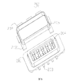
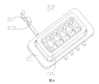
- FIG. 3 is a schematic structural view of an insulating base and a connection terminal of the male connector of the present invention
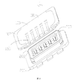
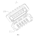
- FIG. 6 is a schematic structural view of an insulating base and a connecting terminal of the female connector of the present invention
- FIG. 7 is a first exploded schematic view of the connector assembly of the present invention.
- FIG. 8 is a second exploded schematic view of the connector assembly of the present invention.
- FIG. 9 is a structural diagram of the connector assembly of the present invention in a combined state
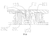
- FIG. 10 is a schematic cross-sectional view of the connector assembly of FIG. 9 along line A-A of the present invention.
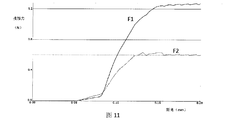
- connection terminal pair of the present invention is a comparison diagram of the contact force between the connection terminal pair of the present invention.
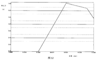
- FIG. 12 is a graph showing the change of the coupling force during the coupling process of the male connector and the female connector
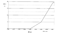
- Fig. 13 is a graph showing the change of the separation force during the separation of the male connector and the female connector.
- Connector assembly 100, male connector; 101, first insulating base; 102, first protective cover; 1021, first fixed terminal; 103, first connection terminal; 104, raised structure; 105, first contact part; 200, female connector; 201, second insulated base; 2011, insulated clamping structure; 202, second protective cover; 2021, second fixed terminal; 203, second connection terminal; 204, The second contact portion; 205, a concave structure.
- the male connector 100 includes a first insulating base 101, a first protective cover 102 connected to a ground potential, and a plurality of first connection terminals 103 each having a first contact portion 105; wherein the first insulating base 101 is made of LCP ( Made of liquid crystal polymer).
- LCP Made of liquid crystal polymer
- the first insulating base 101 is a carrier, which is mainly used to carry the first connection terminal 103 and the first protective cover 102, and the first protective cover 102 includes a closed ring structure surrounding the first connection terminal 103 , And the ring structure is also extended outward to provide a first fixed terminal 1021, the first fixed terminal 1021 is used for electrical connection with the ground potential; preferably, in this embodiment, the closed ring structure is a rectangular ring In addition to the rectangular ring, it can also be an elliptical ring or a ring structure, as long as it can achieve a shielding effect.
- the first protective cover 102, the first connection terminal 103 and the first insulating base 101 are integrally formed by injection molding to avoid the risk that the protective cover may separate from the connector body during the rear-end process.
- the closed ring structure of the first protective cover 102 of the male connector 100 of this embodiment enhances the structural integrity of the connector and reduces the risk of damage due to misuse.
- FIGS. 4 and 5 it is a specific structural schematic diagram of the female connector 200; the second insulating base 201 of the female connector 200, the second protective cover connected to the ground potential, and each having a second contact portion A plurality of 204 second connection terminals 203.
- the second insulating base 201 is made of LCP (Liquid Crystal Polymer).
- FIG. 6 it is a structural schematic diagram of the second connection terminal 203 and the second insulating base 201 in a separated state; and as can be seen from FIG.
- the clamping structure 2011 is used to install the corresponding second connection terminal 203.
- the second insulating base 201 is a carrier, which is mainly used to carry the second connection terminal 203 and the second protective cover 202.
- the second protective cover 202 includes a closed ring structure surrounding the second connection terminal 203, and the closed ring structure further extends outwardly to provide a second fixed terminal 2021, the second fixed terminal 2021 is used for Electrically connected to the ground potential, the insulating clamping structure 2011 is set in a rectangular ring; preferably, in this embodiment, the closed ring structure is a rectangular ring, in addition to the rectangular ring, it can also be an ellipse
- the structure such as a ring or a ring is sufficient as long as it can achieve a shielding effect.
- the second protective cover 202 and the second insulating base 201 are formed by injection molding. When molding, the second protective cover 202 and the second insulating base 201 are insert-molded together, and then the second connection terminal 203 is inserted and fixed to the insulating clamping structure 2011.
- the closed ring structure of the second protective cover 202 of the female connector 200 of this embodiment enhances the structural integrity of the connector and reduces the risk of damage due to misuse.
- the connector assembly 1 includes a male connector and a female connector.
- the male connector refers to the male connector 100
- the female connector refers to the female connector 200
- the male connector 100 is used to mate with the female connector 200.
- FIG. 10 if the male connector is combined with the female connector, the plurality of first connection terminals 103 and the plurality of second connection terminals 203 are respectively connected to the first contact portion 105
- the second contact portion 204 is in contact.
- the first protective cover 102 is provided with a corresponding convex structure 104 and a concave structure 205, when the male connector 100 is inserted
- the corresponding convex structure 104 and the concave structure 205 are engaged, so that the fixing effect between the male connector 100 and the female connector 200 can be further strengthened.
- the material of the protective cover is metal. The male connector 100 and the female connector 200 are locked by the structural features on the metal protective cover.
- the above convex structure 104 and concave structure 205 have less wear during assembly and disassembly of the connector, so that the locking feature on the metal shield will help improve the locking force And the number of assembly/disassembly cycles.
- the closed ring structure for the connector also makes the holding force between the male connector 100 and the female connector 200 slightly better.
- the maximum Von Mises stress of the protective cover caused by the closed ring structure is significantly reduced, while also helping to ensure good RF signal integrity and EMI protection to prevent radiated interference.
- the near-end and far-end crosstalk is known to be less than 30dB at 2GHz and less than 25dB at 8GHz.
- FIG. 10 The structural analysis of the connector assembly 1 in this embodiment, as shown in FIG. 10, when the male connector 100 is inserted into the female connector 200, the contact surface between the first connection terminal 103 and the second connection terminal 203 can be found A force is generated at F1 and F2, and the magnitude of this force is used to evaluate the insertion stability of the overall structure.
- the horizontal axis (X axis) represents the size of the distance, and the unit is mm
- the vertical axis (Y axis) is the size of the force, and the unit is N.
- the magnitude of the contact force of each connection terminal pair evaluated, at this time, the magnitude of the forces of F1 and F2 are 1.26N and 0.53N, respectively.
- This clamping force is sufficient to ensure good electrical contact on the gold-plated surface, because as long as the clamping force is greater than 0.3N, there can be a better clamping force.
Landscapes
- Details Of Connecting Devices For Male And Female Coupling (AREA)
Abstract
本发明提供了一种连接器组件,包括公连接器和母连接器,所述公连接器包括:分别具有第一接触部的多个第一连接端子以及与接地电位连接的第一保护罩;所述母连接器包括:分别具有第二接触部的多个第二连接端子以及与接地电位连接的第二保护罩,若所述公连接器与所述母连接器结合,所述多个第一连接端子与所述多个第二连接端子则分别在所述第一接触部与所述第二接触部接触,且所述第一保护罩与所述第二保护罩相互接触;所述第一保护罩包括包围所述第一连接端子的闭合的环形结构,所述第二保护罩包括包围所述第二连接端子的闭合的环形结构。本发明的连接器组件其闭合的环形结构增强了连接器的结构完整性。
Description
本发明涉及连接器组件以及连接器,尤其涉及用于高频信号的传输的连接器组件以及母连接器。
现有技术的板对板连接器已广泛用于许多电子产品中以连接不同的功能模块。它们为许多产品提供设计,制造和服务灵活性。RF板对板连接器用于将RF模块连接到其他功能电路。由于更高的工作频率范围和对其他信号的干扰的敏感性,在这种连接器设计中存在特定的考虑因素,例如尺寸和屏蔽。
目前,具有类似RF连接器应用,在后续组装到连接器主体过程中,存在将屏蔽结构从主连接器主体上拆卸下来的风险。
【发明内容】
本发明的目的之一在于提供一种连接器组件,其能解决由于误操作而造成连接器损坏的风险。
本发明的目的之二在于提供一种母连接器,其能解决由于误操作而造成连接器损坏的风险。
本发明目的之一中的技术方案如下:
一种连接器组件,包括公连接器和母连接器,所述公连接器包括:分别具有第一接触部的多个第一连接端子以及与接地电位连接的第一保护罩;所述母连接器包括:分别具有第二接触部的多个第二连接端子以及与接地电位连接的第二保护罩,若所述公连接器与所述母连接器结合,所述多个第一连接端子与所述多个第二连接端子则分别在所述第一接触部与所述第二接触部接触,且所述第一保护罩与所述第二保护罩相互接触;所述第一保护罩包括包围所述第一连接端子的闭合的环形结构,所述第二保护 罩包括包围所述第二连接端子的闭合的环形结构。
作为本发明的优选,所述公连接器还包括第一绝缘底座,所述第一保护罩和第一连接端子均固定于所述第一绝缘底座上,所述母连接器还包括第二绝缘底座,所述第二保护罩和第二连接端子均固定于所述第二绝缘底座上。
作为本发明的优选,所述第一保护罩与第一绝缘底座一体注塑成型,所述第二保护罩与第二绝缘底座一体注塑成型。
作为本发明的优选,所述第一保护罩和第二保护罩的形状为长方形的环。
作为本发明的优选,所述第一保护罩的内侧壁设置有凸起结构,所述第二保护罩的外侧壁设置有凹陷结构,当所述公连接器与所述母连接器结合时,所述凸起结构与凹陷结构卡合固定。
作为本发明的优选,所述凸起结构和凹陷结构的数量有四个,且四个所述凸起结构位于长方形的环的四个边角,四个所述凹陷结构位于长方形的环的四个边角。
作为本发明的优选,所述第一保护罩和第二保护罩的材料为金属。
作为本发明的优选,所述第一连接端子和所述第二连接端子向相反的方向延伸。
本发明目的之二中的技术方案如下:
一种母连接器,其是与包括分别具有第一接触部的多个第一连接端子以及与接地电位连接的第一保护罩的公连接器结合的母连接器,其包括:分别具有第二接触部的多个第二连接端子以及与接地电位连接的第二保护罩;若所述公连接器与所述母连接器结合,多个第一连接端子与多个第二连接端子则分别在第一接触部与第二接触部接触,且所述第一保护罩与所述第二保护罩相互接触;所述第二保护罩包括包围所述第二连接端子的闭合的环形结构。
本发明的有益效果在于:本发明的连接器组件通过将保护罩设置为闭合的环形结构,减少将该保护罩从连接器主体上拆卸下来的风险和结构应 力风险,并且闭合的环形结构增强了连接器的结构完整性。
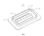
图1为本发明的公连接器的结构图;
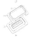
图2为本发明的公连接器的分解示意图;
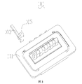
图3为本发明的公连接器的绝缘底座和连接端子的结构示意图;
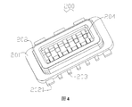
图4为本发明的母连接器的结构图;
图5为本发明的母连接器的分解示意图;
图6为本发明的母连接器的绝缘底座和连接端子的结构示意图
图7为本发明连接器组件的第一分解示意图;
图8为本发明连接器组件的第二分解示意图;
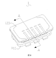
图9为本发明处于组合状态的连接器组件的结构图;
图10为本发明图9中所述连接器组件沿A-A线的剖面示意图;
图11为本发明的连接端子对之间的接触力的对比图;
图12为公连接器和母连接器结合过程中的结合力的变化图;
图13为公连接器和母连接器分离过程中的分离力的变化图。
附图标记:1、连接器组件;100、公连接器;101、第一绝缘底座;102、第一保护罩;1021、第一固定端子;103、第一连接端子;104、凸起结构;105、第一接触部;200、母连接器;201、第二绝缘底座;2011、绝缘卡位结构;202、第二保护罩;2021、第二固定端子;203、第二连接端子;204、第二接触部;205、凹陷结构。
下面结合附图和实施方式对本发明作进一步说明。
如图1和图2所示,其为公连接器100的结构示意图以及分解示意图。所述公连接器100包括第一绝缘底座101,与接地电位连接的第一保护罩102、以及分别具有第一接触部105的多个第一连接端子103;其中第一绝缘底座101由LCP(液晶聚合物)制成。如图3所示,为第一连接端子103与第一绝缘底座101处于分离状态的结构示意图。
所述第一绝缘底座101为一个载体,其主要是用于承载第一连接端子 103和第一保护罩102,所述第一保护罩102包括包围所述第一连接端子103的闭合的环形结构,且该环形结构还向外延伸设置有第一固定端子1021,所述第一固定端子1021用于与接地电位电性连接;优选地,在本实施例中该闭合的环形结构为长方形的环,除了长方形的环之外,还可以是椭圆环或者圆环等结构,其只要能够实现屏蔽作用即可。所述第一保护罩102和第一连接端子103与第一绝缘底座101采取注塑一体成型的方式避免了在后端过程中保护罩可能从连接器主体上分离的风险。本实施例的公连接器100的第一保护罩102的闭合环形结构增强了该连接器的结构完整性,并降低了由于误操作而造成损坏的风险。
如图4和图5所示,其为母连接器200的具体的结构示意图;所述母连接器200第二绝缘底座201,与接地电位连接的第二保护罩、以及分别具有第二接触部204的多个第二连接端子203。其中第二绝缘底座201为LCP(液晶聚合物)制成。如图6所示,为第二连接端子203与第二绝缘底座201处于分离状态的结构示意图;并且从图6可以看出,第二绝缘底座201上设置有绝缘卡位结构2011,所述绝缘卡位结构2011用于安装对应的第二连接端子203。
所述第二绝缘底座201为一个载体,其主要是用于承载第二连接端子203和第二保护罩202。所述第二保护罩202包括包围所述第二连接端子203的闭合的环形结构,且所述闭合的环形结构还向外延伸设置有第二固定端子2021,所述第二固定端子2021用于与接地电位电性连接,所述绝缘卡位结构2011设置于长方形的环内;优选地,在本实施例中该闭合的环形结构为长方形的环,除了长方形的环之外,还可以是椭圆环或者圆环等结构,其只要能够实现屏蔽作用即可。第二保护罩202与第二绝缘底座201采取注塑一体成型的方式。在进行成型的时候,将第二保护罩202和第二绝缘底座201一起嵌件成型,再将第二连接端子203插入固定于绝缘卡位结构2011。本实施例的母连接器200的第二保护罩202的闭合环形结构增强了该连接器的结构完整性,并降低了由于误操作而造成损坏的风险。
如图7、图8和图9所示,依照本发明一实施例的连接器组件1,包括 公连接器和母连接器,在本实施例中,公连接器指的就是公连接器100,母连接器指的是母连接器200,公连接器100用于与母连接器200配合。如图10所示,若所述公连接器与所述母连接器结合,所述多个第一连接端子103与所述多个第二连接端子203则分别在所述第一接触部105与所述第二接触部204接触。
如图1和图5所示的公连接器100和母连接器200,可以知晓,所述第一保护罩102上设置有对应的凸起结构104和凹陷结构205,当将公连接器100插入母连接器200的时候,这时候对应的凸起结构104和凹陷结构205卡合,从而能够进一步加强公连接器100和母连接器200之间的固定效果。在本实施例中所述保护罩的材料采用的金属。通过金属保护罩上的结构特征实现公连接器100和母连接器200的锁定。
由于金属比LCP更硬且具有延展性,在组装和拆卸连接器过程中上述凸起结构104和凹陷结构205具有更小的磨损,从而使得在金属保护罩上锁定特征将有助于改善锁定力和组装/拆卸的循环次数。用于连接器的闭合环形结构还使得公连接器100和母连接器200之间的保持力稍微更好。闭合环形结构引起的保护罩的最大Von Mises应力显著降低,同时还有助于确保良好的RF信号完整性和EMI保护,防止辐射干扰。当配置为G-S-G时,已知近端和远端的串扰在2GHz时小于30dB,在8GHz时小于25dB。
对本实施例中的连接器组件1进行结构分析,如图10所示,当公连接器100插入母连接器200中时,可以发现第一连接端子103和第二连接端子203之间的接触面F1和F2处各产生一个力,这个力的大小用于评估整体结构的插入稳定性。在图10、图11和图12中,横轴(X轴)均表示距离的大小,其单位为mm,纵轴(Y轴)为力的大小,其单位为N。
如图11所示,当公连接器100和母连接器200完全组装时,评估的每个连接端子对的接触力的大小,这时候F1和F2的力的大小分别为1.26N和0.53N。这样的夹持力足以确保镀金表面的良好电接触,因为只要该夹持力大于0.3N就可以有较好的夹持力。
出了对夹持力进行分析之外,还可以对锁定力和解锁力进行分析。如 图12和13所示,可以看出锁定力和解锁力的大小分别为7N和19N。可以发现解锁力更大,由于在一个连接器组件1中解锁力至关重要,因为它可以防止连接器分离,所以需要在进行设计的时候使得解锁力尽量大的,也就使得其相对更不容易分离。
需要说明的是,本发明中所有方向性指示(诸如上、下、内、外、……)仅用于解释在某一特定姿态(如附图所示)下各部件之间的相对位置关系等,如果该特定姿态发生改变时,则该方向性指示也相应地随之改变。
以上所述的仅是本发明的实施方式,在此应当指出,对于本领域的普通技术人员来说,在不脱离本发明创造构思的前提下,还可以做出改进,但这些均属于本发明的保护范围。
Claims (9)
- 一种连接器组件,包括公连接器和母连接器,其特征在于,所述公连接器包括:分别具有第一接触部的多个第一连接端子以及与接地电位连接的第一保护罩;所述母连接器包括:分别具有第二接触部的多个第二连接端子以及与接地电位连接的第二保护罩,若所述公连接器与所述母连接器结合,所述多个第一连接端子与所述多个第二连接端子则分别在所述第一接触部与所述第二接触部接触,且所述第一保护罩与所述第二保护罩相互接触;所述第一保护罩包括包围所述第一连接端子的闭合的环形结构,所述第二保护罩包括包围所述第二连接端子的闭合的环形结构。
- 根据权利要求1所述的连接器组件,其特征在于:所述公连接器还包括第一绝缘底座,所述第一保护罩和第一连接端子均固定于所述第一绝缘底座上,所述母连接器还包括第二绝缘底座,所述第二保护罩和第二连接端子均固定于所述第二绝缘底座上。
- 根据权利要求2所述的连接器组件,其特征在于:所述第一保护罩与第一绝缘底座一体注塑成型,所述第二保护罩与第二绝缘底座一体注塑成型。
- 根据权利要求1所述的连接器组件,其特征在于:所述第一保护罩和第二保护罩的形状为长方形的环。
- 根据权利要求4所述的连接器组件,其特征在于:所述第一保护罩的内侧壁设置有凸起结构,所述第二保护罩的外侧壁设置有凹陷结构,当所述公连接器与所述母连接器结合时,所述凸起结构与凹陷结构卡合固定。
- 根据权利要求5所述的连接器组件,其特征在于:所述凸起结构和凹陷结构的数量有四个,且四个所述凸起结构位于长方形的环的四个边角,四个所述凹陷结构位于长方形的环的四个边角。
- 根据权利要求1-6中任意一项所述的连接器组件,其特征在于:所述第一保护罩和第二保护罩的材料为金属。
- 根据权利要求1所述的连接器组件,其特征在于:所述第一连接端 子和所述第二连接端子向相反的方向延伸。
- 一种母连接器,其是与包括分别具有第一接触部的多个第一连接端子以及与接地电位连接的第一保护罩的公连接器结合的母连接器,其特征在于,其包括:分别具有第二接触部的多个第二连接端子以及与接地电位连接的第二保护罩;若所述公连接器与所述母连接器结合,多个第一连接端子与多个第二连接端子则分别在第一接触部与第二接触部接触,且所述第一保护罩与所述第二保护罩相互接触;所述第二保护罩包括包围所述第二连接端子的闭合的环形结构。
Priority Applications (1)
| Application Number | Priority Date | Filing Date | Title |
|---|---|---|---|
| PCT/CN2018/125935 WO2020140170A1 (zh) | 2018-12-30 | 2018-12-30 | 连接器组件以及母连接器 |
Applications Claiming Priority (1)
| Application Number | Priority Date | Filing Date | Title |
|---|---|---|---|
| PCT/CN2018/125935 WO2020140170A1 (zh) | 2018-12-30 | 2018-12-30 | 连接器组件以及母连接器 |
Publications (1)
| Publication Number | Publication Date |
|---|---|
| WO2020140170A1 true WO2020140170A1 (zh) | 2020-07-09 |
Family
ID=71406504
Family Applications (1)
| Application Number | Title | Priority Date | Filing Date |
|---|---|---|---|
| PCT/CN2018/125935 Ceased WO2020140170A1 (zh) | 2018-12-30 | 2018-12-30 | 连接器组件以及母连接器 |
Country Status (1)
| Country | Link |
|---|---|
| WO (1) | WO2020140170A1 (zh) |
Citations (2)
| Publication number | Priority date | Publication date | Assignee | Title |
|---|---|---|---|---|
| TW201820709A (zh) * | 2016-10-21 | 2018-06-01 | 鴻騰精密科技股份有限公司 | 插座連接器 |
| CN208173937U (zh) * | 2018-04-17 | 2018-11-30 | 昆山雷匠通信科技有限公司 | 多pin板对板式射频连接器 |
-
2018
- 2018-12-30 WO PCT/CN2018/125935 patent/WO2020140170A1/zh not_active Ceased
Patent Citations (2)
| Publication number | Priority date | Publication date | Assignee | Title |
|---|---|---|---|---|
| TW201820709A (zh) * | 2016-10-21 | 2018-06-01 | 鴻騰精密科技股份有限公司 | 插座連接器 |
| CN208173937U (zh) * | 2018-04-17 | 2018-11-30 | 昆山雷匠通信科技有限公司 | 多pin板对板式射频连接器 |
Similar Documents
| Publication | Publication Date | Title |
|---|---|---|
| US11211725B2 (en) | Multipolar connector | |
| US20170229810A1 (en) | Electrical connector and cable connector having same | |
| CN113054470A (zh) | 一种公座、母座及板对板射频连接器 | |
| WO2020052318A1 (zh) | 板对板型射频插头及插座 | |
| CN204216324U (zh) | 接地良好的高速传输母端连接器 | |
| JPS5928955B2 (ja) | 電気的コネクタ | |
| TWI648919B (zh) | 插座連接器及移動設備 | |
| EP3751671A1 (en) | Coaxial cable male connector for transmitting super-high frequency signals | |
| CN104733882B (zh) | 直立型插座电连接器 | |
| CN113924700A (zh) | 阴型多极连接器以及具备该阴型多极连接器的多极连接器组 | |
| US9147979B1 (en) | Electric connector | |
| CN112913089A (zh) | 同轴连接器装置 | |
| CN111029858B (zh) | 一种连接器 | |
| TW201424158A (zh) | 插座連接器 | |
| CN206893923U (zh) | 电路基板用电连接器 | |
| US11936140B2 (en) | Radio-frequency connector with high transmission performance | |
| TWI748694B (zh) | 一種高傳輸性能的射頻連接器 | |
| US20240429664A1 (en) | Plug connector and radio frequency connector assembly | |
| TWI696324B (zh) | 一體成型的連接器接地結構 | |
| WO2020140170A1 (zh) | 连接器组件以及母连接器 | |
| TWI726486B (zh) | 射頻連接器 | |
| TWI618317B (zh) | 電連接器 | |
| WO2021168873A1 (zh) | 一种多级连接器组件及母连接器 | |
| CN205070056U (zh) | 插座电连接器 | |
| CN210489982U (zh) | 一种改进的板连接器 |
Legal Events
| Date | Code | Title | Description |
|---|---|---|---|
| 121 | Ep: the epo has been informed by wipo that ep was designated in this application |
Ref document number: 18945379 Country of ref document: EP Kind code of ref document: A1 |
|
| NENP | Non-entry into the national phase |
Ref country code: DE |
|
| 122 | Ep: pct application non-entry in european phase |
Ref document number: 18945379 Country of ref document: EP Kind code of ref document: A1 |