WO2020138473A1 - プリフォームの製造方法および複合材料成形品の製造方法ならびに型 - Google Patents
プリフォームの製造方法および複合材料成形品の製造方法ならびに型 Download PDFInfo
- Publication number
- WO2020138473A1 WO2020138473A1 PCT/JP2019/051553 JP2019051553W WO2020138473A1 WO 2020138473 A1 WO2020138473 A1 WO 2020138473A1 JP 2019051553 W JP2019051553 W JP 2019051553W WO 2020138473 A1 WO2020138473 A1 WO 2020138473A1
- Authority
- WO
- WIPO (PCT)
- Prior art keywords
- reinforcing fiber
- base material
- mold
- fiber base
- preform
- Prior art date
Links
Images


Classifications
-
- B—PERFORMING OPERATIONS; TRANSPORTING
- B29—WORKING OF PLASTICS; WORKING OF SUBSTANCES IN A PLASTIC STATE IN GENERAL
- B29B—PREPARATION OR PRETREATMENT OF THE MATERIAL TO BE SHAPED; MAKING GRANULES OR PREFORMS; RECOVERY OF PLASTICS OR OTHER CONSTITUENTS OF WASTE MATERIAL CONTAINING PLASTICS
- B29B11/00—Making preforms
- B29B11/14—Making preforms characterised by structure or composition
- B29B11/16—Making preforms characterised by structure or composition comprising fillers or reinforcement
-
- B—PERFORMING OPERATIONS; TRANSPORTING
- B29—WORKING OF PLASTICS; WORKING OF SUBSTANCES IN A PLASTIC STATE IN GENERAL
- B29C—SHAPING OR JOINING OF PLASTICS; SHAPING OF MATERIAL IN A PLASTIC STATE, NOT OTHERWISE PROVIDED FOR; AFTER-TREATMENT OF THE SHAPED PRODUCTS, e.g. REPAIRING
- B29C70/00—Shaping composites, i.e. plastics material comprising reinforcements, fillers or preformed parts, e.g. inserts
- B29C70/04—Shaping composites, i.e. plastics material comprising reinforcements, fillers or preformed parts, e.g. inserts comprising reinforcements only, e.g. self-reinforcing plastics
- B29C70/06—Fibrous reinforcements only
- B29C70/10—Fibrous reinforcements only characterised by the structure of fibrous reinforcements, e.g. hollow fibres
- B29C70/16—Fibrous reinforcements only characterised by the structure of fibrous reinforcements, e.g. hollow fibres using fibres of substantial or continuous length
- B29C70/20—Fibrous reinforcements only characterised by the structure of fibrous reinforcements, e.g. hollow fibres using fibres of substantial or continuous length oriented in a single direction, e.g. roofing or other parallel fibres
-
- B—PERFORMING OPERATIONS; TRANSPORTING
- B29—WORKING OF PLASTICS; WORKING OF SUBSTANCES IN A PLASTIC STATE IN GENERAL
- B29B—PREPARATION OR PRETREATMENT OF THE MATERIAL TO BE SHAPED; MAKING GRANULES OR PREFORMS; RECOVERY OF PLASTICS OR OTHER CONSTITUENTS OF WASTE MATERIAL CONTAINING PLASTICS
- B29B11/00—Making preforms
- B29B11/06—Making preforms by moulding the material
- B29B11/12—Compression moulding
-
- B—PERFORMING OPERATIONS; TRANSPORTING
- B29—WORKING OF PLASTICS; WORKING OF SUBSTANCES IN A PLASTIC STATE IN GENERAL
- B29C—SHAPING OR JOINING OF PLASTICS; SHAPING OF MATERIAL IN A PLASTIC STATE, NOT OTHERWISE PROVIDED FOR; AFTER-TREATMENT OF THE SHAPED PRODUCTS, e.g. REPAIRING
- B29C43/00—Compression moulding, i.e. applying external pressure to flow the moulding material; Apparatus therefor
- B29C43/02—Compression moulding, i.e. applying external pressure to flow the moulding material; Apparatus therefor of articles of definite length, i.e. discrete articles
- B29C43/14—Compression moulding, i.e. applying external pressure to flow the moulding material; Apparatus therefor of articles of definite length, i.e. discrete articles in several steps
-
- B—PERFORMING OPERATIONS; TRANSPORTING
- B29—WORKING OF PLASTICS; WORKING OF SUBSTANCES IN A PLASTIC STATE IN GENERAL
- B29C—SHAPING OR JOINING OF PLASTICS; SHAPING OF MATERIAL IN A PLASTIC STATE, NOT OTHERWISE PROVIDED FOR; AFTER-TREATMENT OF THE SHAPED PRODUCTS, e.g. REPAIRING
- B29C43/00—Compression moulding, i.e. applying external pressure to flow the moulding material; Apparatus therefor
- B29C43/32—Component parts, details or accessories; Auxiliary operations
- B29C43/34—Feeding the material to the mould or the compression means
-
- B—PERFORMING OPERATIONS; TRANSPORTING
- B29—WORKING OF PLASTICS; WORKING OF SUBSTANCES IN A PLASTIC STATE IN GENERAL
- B29C—SHAPING OR JOINING OF PLASTICS; SHAPING OF MATERIAL IN A PLASTIC STATE, NOT OTHERWISE PROVIDED FOR; AFTER-TREATMENT OF THE SHAPED PRODUCTS, e.g. REPAIRING
- B29C70/00—Shaping composites, i.e. plastics material comprising reinforcements, fillers or preformed parts, e.g. inserts
- B29C70/04—Shaping composites, i.e. plastics material comprising reinforcements, fillers or preformed parts, e.g. inserts comprising reinforcements only, e.g. self-reinforcing plastics
- B29C70/06—Fibrous reinforcements only
- B29C70/10—Fibrous reinforcements only characterised by the structure of fibrous reinforcements, e.g. hollow fibres
- B29C70/16—Fibrous reinforcements only characterised by the structure of fibrous reinforcements, e.g. hollow fibres using fibres of substantial or continuous length
- B29C70/24—Fibrous reinforcements only characterised by the structure of fibrous reinforcements, e.g. hollow fibres using fibres of substantial or continuous length oriented in at least three directions forming a three dimensional structure
-
- B—PERFORMING OPERATIONS; TRANSPORTING
- B29—WORKING OF PLASTICS; WORKING OF SUBSTANCES IN A PLASTIC STATE IN GENERAL
- B29C—SHAPING OR JOINING OF PLASTICS; SHAPING OF MATERIAL IN A PLASTIC STATE, NOT OTHERWISE PROVIDED FOR; AFTER-TREATMENT OF THE SHAPED PRODUCTS, e.g. REPAIRING
- B29C70/00—Shaping composites, i.e. plastics material comprising reinforcements, fillers or preformed parts, e.g. inserts
- B29C70/04—Shaping composites, i.e. plastics material comprising reinforcements, fillers or preformed parts, e.g. inserts comprising reinforcements only, e.g. self-reinforcing plastics
- B29C70/28—Shaping operations therefor
- B29C70/30—Shaping by lay-up, i.e. applying fibres, tape or broadsheet on a mould, former or core; Shaping by spray-up, i.e. spraying of fibres on a mould, former or core
- B29C70/34—Shaping by lay-up, i.e. applying fibres, tape or broadsheet on a mould, former or core; Shaping by spray-up, i.e. spraying of fibres on a mould, former or core and shaping or impregnating by compression, i.e. combined with compressing after the lay-up operation
- B29C70/345—Shaping by lay-up, i.e. applying fibres, tape or broadsheet on a mould, former or core; Shaping by spray-up, i.e. spraying of fibres on a mould, former or core and shaping or impregnating by compression, i.e. combined with compressing after the lay-up operation using matched moulds
-
- B—PERFORMING OPERATIONS; TRANSPORTING
- B29—WORKING OF PLASTICS; WORKING OF SUBSTANCES IN A PLASTIC STATE IN GENERAL
- B29C—SHAPING OR JOINING OF PLASTICS; SHAPING OF MATERIAL IN A PLASTIC STATE, NOT OTHERWISE PROVIDED FOR; AFTER-TREATMENT OF THE SHAPED PRODUCTS, e.g. REPAIRING
- B29C70/00—Shaping composites, i.e. plastics material comprising reinforcements, fillers or preformed parts, e.g. inserts
- B29C70/04—Shaping composites, i.e. plastics material comprising reinforcements, fillers or preformed parts, e.g. inserts comprising reinforcements only, e.g. self-reinforcing plastics
- B29C70/28—Shaping operations therefor
- B29C70/40—Shaping or impregnating by compression not applied
- B29C70/42—Shaping or impregnating by compression not applied for producing articles of definite length, i.e. discrete articles
- B29C70/46—Shaping or impregnating by compression not applied for producing articles of definite length, i.e. discrete articles using matched moulds, e.g. for deforming sheet moulding compounds [SMC] or prepregs
- B29C70/461—Rigid movable compressing mould parts acting independently from opening or closing action of the main mould
-
- B—PERFORMING OPERATIONS; TRANSPORTING
- B29—WORKING OF PLASTICS; WORKING OF SUBSTANCES IN A PLASTIC STATE IN GENERAL
- B29C—SHAPING OR JOINING OF PLASTICS; SHAPING OF MATERIAL IN A PLASTIC STATE, NOT OTHERWISE PROVIDED FOR; AFTER-TREATMENT OF THE SHAPED PRODUCTS, e.g. REPAIRING
- B29C70/00—Shaping composites, i.e. plastics material comprising reinforcements, fillers or preformed parts, e.g. inserts
- B29C70/04—Shaping composites, i.e. plastics material comprising reinforcements, fillers or preformed parts, e.g. inserts comprising reinforcements only, e.g. self-reinforcing plastics
- B29C70/28—Shaping operations therefor
- B29C70/54—Component parts, details or accessories; Auxiliary operations, e.g. feeding or storage of prepregs or SMC after impregnation or during ageing
-
- B—PERFORMING OPERATIONS; TRANSPORTING
- B29—WORKING OF PLASTICS; WORKING OF SUBSTANCES IN A PLASTIC STATE IN GENERAL
- B29C—SHAPING OR JOINING OF PLASTICS; SHAPING OF MATERIAL IN A PLASTIC STATE, NOT OTHERWISE PROVIDED FOR; AFTER-TREATMENT OF THE SHAPED PRODUCTS, e.g. REPAIRING
- B29C43/00—Compression moulding, i.e. applying external pressure to flow the moulding material; Apparatus therefor
- B29C43/02—Compression moulding, i.e. applying external pressure to flow the moulding material; Apparatus therefor of articles of definite length, i.e. discrete articles
- B29C43/14—Compression moulding, i.e. applying external pressure to flow the moulding material; Apparatus therefor of articles of definite length, i.e. discrete articles in several steps
- B29C2043/141—Compression moulding, i.e. applying external pressure to flow the moulding material; Apparatus therefor of articles of definite length, i.e. discrete articles in several steps for making single layer articles
- B29C2043/142—Compression moulding, i.e. applying external pressure to flow the moulding material; Apparatus therefor of articles of definite length, i.e. discrete articles in several steps for making single layer articles by moving a single mould or the article progressively, i.e. portionwise
Definitions
- the present invention relates to a preform manufacturing method, a composite material molded article manufacturing method, and a mold.
- a composite material molded product obtained by impregnating a matrix resin into a reinforced fiber base material including reinforced fibers and curing is generally lightweight and has excellent mechanical properties. Therefore, it is widely used for various applications in various fields such as sports, aerospace, and general industry.
- the reinforcing fiber base material is usually flat (sheet-like), and a method is known in which it is shaped into a shape of a composite material molded article or a shape close to it before undergoing preform before being cured. ..
- a composite material molded article is manufactured by further compression-molding the preform.
- As a method of manufacturing the preform there is known a method of manufacturing a plurality of partial preforms and bonding them at their bonding ends to manufacture an integral preform corresponding to a composite material molded article ( For example, see Patent Document 1).
- the above-mentioned manufacturing method joins the partial preforms to manufacture the preform, it is possible to sufficiently suppress the occurrence of wrinkles in the preform even in the case of a composite material molded product having a complicated shape. Therefore, a composite material molded article having an excellent appearance can be manufactured.
- the preform is manufactured by joining the partial preforms, compared with the composite material molded product manufactured from the preform formed by integrally molding the reinforcing fiber base material, For example, the strength at the joint may be low.
- the above manufacturing method since the partial preforms are joined to manufacture the preform, it is necessary to carry out various steps therefor. For example, it is necessary to cut the reinforcing fiber base material so that the partial preforms are lined up with each other and properly overlapped in the thickness direction. Further, it is necessary to bond the produced partial preforms to each other. As described above, the above-mentioned manufacturing method has room for examination from the viewpoint of mechanical properties and productivity of the composite material molded product.
- An aspect of the present invention is to realize production of a composite material molded product that has an excellent appearance, can suppress deterioration of mechanical properties, and is excellent in productivity.
- a method for producing a preform according to an aspect of the present invention is such that at least a part of a planar reinforcing fiber base material containing a reinforcing fiber and a matrix resin composition is sheared and/or compressed.
- a second step of applying a directional force is such that at least a part of a planar reinforcing fiber base material containing a reinforcing fiber and a matrix resin composition is sheared and/or compressed.
- a method for manufacturing a composite material molded article according to an aspect of the present invention, a step of manufacturing a preform by the method for manufacturing a preform described above, by heating and pressurizing the preform Manufacturing the composite material molded article.
- a method for producing a composite material molded article according to an aspect of the present invention is a shear deformation of at least a part of a planar reinforcing fiber base material containing a reinforcing fiber and a matrix resin composition.
- a method for producing a composite material molded article by compressing and/or compressing to produce a composite material molded article comprising: an end of a portion of the reinforcing fiber base material to be subjected to shear deformation and/or compression deformation; and adjacent to the portion.
- a mold according to one aspect of the present invention is a mold having an upper mold and a lower mold, and one or both of the upper mold and the lower mold are divided into a plurality of parts. And a movable split type, and a part of the multiple split types, an end of a portion of the planar reinforcing fiber base material containing the reinforcing fiber to undergo shear deformation and/or compression deformation, and the portion.
- a second mechanism for applying a force in the out-of-plane direction of the base material is a mold having an upper mold and a lower mold, and one or both of the upper mold and the lower mold are divided into a plurality of parts.
- a movable split type, and a part of the multiple split types an end of a portion of the planar reinforcing fiber base material
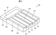
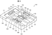
- FIG. 5 It is a figure which shows typically the state which made the upper division type drive part shown by FIG. 5 visible. It is a figure which shows typically an example of a structure of the lower division type
- a method of manufacturing a preform according to an embodiment of the present invention includes a method of pressing a reinforcing fiber base material against a preform mold, and shearing and/or compressing and deforming at least a part of the reinforcing fiber base material for reinforcement.
- the fiber base material is shaped into a three-dimensional shape.
- a and/or B means "one or both of A and B.”
- the reinforcing fiber base material has a planar shape. That is, the reinforcing fiber base material has a spread in the plane direction.
- the flat reinforcing fiber base material is, for example, a sheet of the reinforcing fiber base material.
- the reinforcing fiber base material can be appropriately selected from known base materials that can be used in the production of preforms and composite material molded products, as long as they are planar. The reinforcing fiber base material will be described in detail later.
- the preform type can be appropriately determined within a range that can be used for shaping the reinforcing fiber base material.
- the preform mold will be described later in detail with reference to the drawings.
- the reinforcing fiber substrate is shaped into a three-dimensional shape.
- the three-dimensional shape means a three-dimensional shape, and includes one of a flat surface, a developable surface, and a three-dimensional curved surface, or a combination of two or more.
- the developable surface refers to a surface that becomes a flat surface by expanding without expanding and contracting.
- An example of the developable surface is a conical surface.
- a three-dimensional curved surface refers to a surface that cannot be formed without expanding and contracting the flat surface, and refers to a surface that cannot be expanded into a flat surface.
- a spherical surface is an example of the three-dimensional curved surface.
- the shape to be shaped is composed of a developable surface and/or a three-dimensional shape, complicated deformation including shearing, compression and both occurs at the time of shaping, and therefore, the method for manufacturing a preform in the present embodiment.
- the advantage of is likely to become more prominent.
- the reinforcing fiber base material is shaped by at least a part thereof being deformed by shear deformation and/or by compressive deformation, or both of them.
- a preform is manufactured by shaping the reinforcing fiber base material. Further, according to the present embodiment, it is possible to obtain a preform having a good appearance even when a three-dimensional shape in which shear deformation occurs is shaped. Further, even when compression deformation occurs in addition to shear deformation, a preform having a good appearance can be obtained.
- the shaping of the reinforcing fiber base material in the present embodiment includes the following first step and second step.
- the first step is a step of fixing the end portion of the portion of the reinforcing fiber base material to be subjected to shear deformation and/or compression deformation or the portion adjacent to the portion to the preform mold.
- the “site to be subjected to shear deformation and/or compression deformation” in the first step is at least a part of the reinforcing fiber base material.
- it is at least one of a site that is sheared and deformed by a second step, which will be described later, and a site that is compressed and deformed by the second step.
- the site of shearing/compressive deformation is determined according to the shape to be shaped.
- the shape to be shaped is the shape of the composite material molded product, or a shape close to the shape of the composite material molded product to be realized as a preform therefor.
- the portion of the reinforcing fiber base material that is fixed in the first step is an end portion of the shear/compression deformation target portion, a portion adjacent to the shear/compression deformation target portion, or both of them.
- the end of the shearing/compressing deformation target portion refers to a portion inside the shearing/compression deformation target portion but at the edge, not inside.
- the portion adjacent to the shear/compression deformation target portion is a portion outside the shear/compression deformation target portion and not separated from the shear/compression deformation target portion.
- the part may be, for example, the starting point of shear deformation, or may be the fixed end that defines the part that undergoes compressive deformation.
- the direction of the force applied to the part of the reinforcing fiber base material can be predicted when the reinforcing fiber base material is fixed and shaped in the preform mold. Therefore, it is possible to predict a portion where shear deformation and compression deformation occur in the reinforcing fiber base material due to the shaping accompanied with the fixing.
- the portion fixed in the reinforcing fiber base material in the first step can be appropriately determined according to the shape of the preform mold.
- the portion fixed in the first step is a portion formed of a flat surface (for example, the above-mentioned flat surface or developable surface) from the viewpoint of suppressing the generation of wrinkles.
- the portion fixed in the first step is the highest portion of the preform lower mold.
- the two directions include the fiber axis direction (also referred to as “orientation direction”) in the reinforcing fiber base material. ..
- the portion fixed in the first step if there is a high portion in the central portion of the lower mold, may include one or both of the one end portion and the central portion of the lower mold, the reinforcing fiber at the time of shaping It is preferable from the viewpoint of enhancing the followability of the base material.
- “Fixing” in the first step means that the portion of the reinforcing fiber base material to be fixed does not substantially move relative to the preform mold.
- the portion of the reinforcing fiber base material that is fixed in the first step does not have to move in either the out-of-plane direction or the in-plane direction, and shear/compression deformation is sufficient in the second step. You may move in the range realized.
- the in-plane direction means a horizontal direction in a plane including the planar reinforcing fiber base material
- the out-of-plane direction means a direction orthogonal to the in-plane direction.
- the part where the reinforcing fiber base material is pressed may be temporarily pressed so that the reinforcing fiber base material can move by sliding.
- temporary pressing when the reinforcing fiber base material has poor extensibility, the reinforcing fiber base material is drawn from the periphery of the pressed part toward the inside of the mold, so the end parts after shaping are often not aligned. .. Therefore, after shaping, it is necessary to perform trimming so that the shape should be shaped. Therefore, fixing is preferable to temporary pressing.
- the method of fixing a part of the reinforcing fiber base material to the preform mold can be appropriately determined by further considering the structure of the reinforcing fiber base material.
- Examples of the method include a method of adhering and fixing the reinforcing fiber base material to the preform mold with an adhesive member other than the reinforcing fiber base material, and a method of using the adhesiveness of the reinforcing fiber base material to push The method of fixing to the reform mold and the fixing by vacuum deaeration are included.
- Examples of adhesive members for fixing by adhesion include heat-resistant tape having an adhesive layer and adhesive.
- the adhesive may be the same type of resin as the matrix resin impregnated in the reinforcing fiber base material, may be a different type of resin, or may include both of them. Further, it may be an adhesive forming the above-mentioned adhesive layer.
- Examples of fixing using adhesiveness include fixing by heating and fixing by applying pressure.
- Fixing by heating is, for example, when the reinforcing fiber base material further contains a matrix resin composition described below, the reinforcing fiber base material into a preform type due to the adhesiveness of the matrix resin composition exuded from the reinforcing fiber base material by heating. It is a method of fixing relatively.
- the heating conditions such as temperature and time for fixing by heating can be appropriately determined within a range where sufficient adhesive strength due to the tackiness can be obtained.
- Fixing by pressure is a method of relatively fixing the reinforcing fiber base material to the preform mold due to the adhesiveness of the matrix resin composition that exudes from the reinforcing fiber base material by pressurizing.
- Pressurization conditions such as pressure can be appropriately determined within a range in which sufficient adhesive strength due to the tackiness can be obtained, as in the case of fixing by heating.
- the fixing by vacuum deaeration is performed by covering the reinforcing fiber base material and the preform mold in the range to be fixed in an airtight manner, and by deaerating the covered portion and sufficiently reducing the pressure, the portion in the airtight covered portion is pressed.
- This is a method of fixing a reinforcing fiber base material to a reforming type.
- the conditions of vacuum degassing such as the degree of reduced pressure can be appropriately determined within a range in which sufficient fixing strength can be obtained by the reduced pressure.
- the first step when the fixed reinforcing fiber base material is subsequently pressed by the fitting of the preform mold (the lower mold and the upper mold), a portion that causes shear deformation in the reinforcing fiber base material and The portion that causes compression deformation is defined.
- the second step is a step of applying a force in the out-of-plane direction to the shearing/compressive deformation target site after the first step.
- the portion to which the force in the out-of-plane direction is applied may be the entire shearing/compressive deformation target portion, but within a range capable of substantially preventing wrinkles from occurring in the preform, It may be a part of the compression deformation target site.
- the part of the shearing/compressing deformation target portion to which the force in the out-of-plane direction should be applied can be appropriately determined within a range that can substantially prevent the generation of wrinkles in the preform.
- the largest deformation amount A portion having a relatively large deformation amount, a portion in which the deformation amount exceeds a certain threshold value, and a portion in which an average value of the deformation amount in an arbitrary region exceeds a certain threshold value are included.
- the part that applies a force in the out-of-plane direction may be a part that causes shear deformation, a part that causes compressive deformation, or a part adjacent to them. It is preferable that the portion that applies a force in the out-of-plane direction is a portion that undergoes compressive deformation, from the viewpoint of suppressing floating due to compression, and from the viewpoint of more effectively preventing the occurrence of wrinkles in the preform.
- the fact that the portion that applies the force in the out-of-plane direction is adjacent to the portion that causes the shear deformation means that one end of the portion that causes the shear deformation is fixed, so that the other end is given a force in the out-of-plane direction. Become. Therefore, it is preferable from the viewpoint that shear deformation can be efficiently generated.
- FIG. 1 is a diagram schematically showing a sample of a reinforcing fiber base material for measuring the amount of deformation of the reinforcing fiber base material.
- FIG. 2 is a diagram schematically showing a cross-shaped pattern of the sample of FIG. 1 before and after shear deformation of the sample.
- a sample S of a reinforcing fiber base material having a grid-like pattern Cu as shown in FIG. 1 is prepared.
- the planar shape of the sample S and the planar shape of each grid in the pattern Cu are both rectangular.
- One angle ⁇ 1 of the pattern Cu is, for example, 90° as shown in FIG.
- each of the edges of the sample S including at least a pair of opposing sides is clamped by a jig.
- a force in a direction that gives a shearing force to the sample S (for example, a force in a direction indicated by an arrow F when the lower part of the sample S is fixed in FIG. 2) is applied to each of the jigs to apply the flat surface of the sample S. Transform the shape.
- the angle ⁇ 2 at one corner of the pattern Cu becomes larger than 90°, as shown in FIG. 2, for example.
- the angle ⁇ 2 at this time is the amount of deformation.
- the size of the partial deformation amount of the reinforcing fiber base material when shaped into the shape of the preform Desired.
- An arbitrary portion of the thus obtained large deformation amount may be determined as the portion to which the force in the out-of-plane direction should be applied in the second step.
- the force in the out-of-plane direction in the second step means the force in the direction orthogonal to the plane of the reinforcing fiber base material.
- the force in the direction of pressing the reinforcing fiber base material toward the lower mold of the preform type is shown.
- the force in the out-of-plane direction can be applied to a predetermined portion of the reinforcing fiber base material by various methods.
- the force in the out-of-plane direction can be applied to the predetermined portion by pressing by the upper mold for pressing the reinforcing fiber base material toward the lower mold of the preform mold.
- the force in the out-of-plane direction is applied to the predetermined portion of the lower part of the preform mold by pressing with a pressing member for pressing the reinforcing fiber base material to a portion corresponding to the predetermined portion.
- a pressing member for example, an elastic member (for example, a member made of foamed polyethylene) having the above-described planar shape in the lower mold can be used.
- the second step it is possible to induce out-of-plane deformation of the reinforcing fiber base material by performing shear deformation exceeding the amount of deformation of the reinforcing fiber base material on the shear/compressive deformation target site. That is, the reinforcing fiber base material having a deformation amount smaller than the deformation amount required for the shape of the preform may be sheared/compressed in the second step. In this case, the portion of the reinforcing fiber base material to which the force is applied in the out-of-plane direction is first deformed to the deformation amount of the reinforcing fiber base material.
- a reinforcing fiber base material having a deformation amount less than the deformation amount required for the shape of the preform is applied. Is possible.
- the position to be pressed in the first step is at a shallower position in the pressing direction, and the position to be pressed in the second step is at a deeper position. It is preferable. This is preferable from the viewpoint of generating shear and compression in the reinforcing fiber base material while utilizing the self-weight and drape property of the reinforcing fiber base material so as not to generate wrinkles.
- the reinforcing fiber base material to which a force is applied in the out-of-plane direction is preferably fixed in at most three directions out of four directions defined by two axes orthogonal to each other on a plane. ..
- the reinforcing fiber base material to which the force in the out-of-plane direction is applied has a free end on at least one side of the above four directions. Therefore, when a certain direction is defined with respect to the mold, if there is a portion having a different length along the mold with respect to the direction, when a reinforcing fiber base material that is difficult to stretch is used, the force in the out-of-plane direction is used. A part of the reinforcing fiber substrate is drawn into the mould.
- the reinforcing fiber base material easily moves in the in-plane direction from the free end side. Therefore, it is preferable from the viewpoint of suppressing the generation of wrinkles in the prepreg and the composite material molded product.
- the preform manufacturing method according to the present embodiment may further include steps other than the above-described first and second steps within a range in which the effects of the present embodiment can be obtained.
- the preform manufacturing method may further include a movement assisting step in the second step.
- the movement assisting step is a step of assisting movement of the reinforcing fiber base material in the in-plane direction caused by shear deformation and/or compression deformation.
- shear deformation and/or compression deformation caused by applying a force in the out-of-plane direction
- the reinforcing fiber base material is previously fixed to the mold. Therefore, when there is a portion where the amount of deformation changes stepwise, a portion that gradually moves in the in-plane direction also occurs in the reinforcing fiber base material with the deformation. If the movement in the in-plane direction is insufficient, it may be complemented and wrinkles may occur at another site.
- the movement assisting process assists the deformation of the portion of the base material having a relatively large degree of deformation
- the portion of the base material having a relatively large degree of deformation or a portion adjacent to the portion is strengthened in the in-plane direction. It assists in moving towards a pre-fixed part of the fiber substrate.
- the movement assisting step can be performed by positively moving the reinforcing fiber base material in the in-plane direction. For example, it is possible to carry out using a third mechanism which will be described later for the mold.
- the slipperiness of the reinforcing fiber base material with respect to the mold from the viewpoint of smoothly performing the movement in the in-plane direction and suppressing the generation of wrinkles.
- the slipperiness can be enhanced by, for example, providing a layer having excellent releasability such as a fluororesin layer on the surface of the mold corresponding to the portion to be moved in the in-plane direction of the reinforcing fiber base material. ..
- the above-mentioned slipperiness can be enhanced by covering the surface of the reinforcing fiber base material contacting the mold with a covering material such as a protective film.
- the movement assisting step independently performs applying a force in the out-of-plane direction to a portion to be subjected to shear deformation and/or compression deformation, and assisting the movement of the reinforcing fiber base material in the in-plane direction thereby. May be. Performing both of them at the same time is preferable from the viewpoint of suppressing the generation of wrinkles in the reinforcing fiber base material.
- the method for producing the preform may further include a third step of pressing the entire reinforcing fiber base material after the second step.
- the third step can be carried out by pressing the reinforcing fiber base with an upper mold corresponding to the lower mold of the preform mold.
- the reinforcing fiber base material is fixed in the first step and is deformed by applying a force in the out-of-plane direction in the second step, these pressed parts are pressed. It can be carried out by pressing the surface of the reinforcing fiber base material other than the above toward the lower mold of the preform mold.
- the reinforcing fiber base material is more strongly shaped, and a better preform can be manufactured.
- the preform manufacturing method according to the present embodiment may further include a temporary pressing step of temporarily pressing the reinforcing fiber base material as the other step described above.
- the temporary pressing step applies a force in an out-of-plane direction to an arbitrary portion of the reinforcing fiber base material, and is a step of allowing the in-plane direction movement by not completely fixing the reinforcing fiber base material.
- the temporary pressing step can be performed, for example, by pressing the reinforcing fiber substrate toward the lower mold with an appropriate force by the upper mold or another member protruding from the upper mold.
- the temporary pressing step is performed, for example, on the end portion of the reinforcing fiber base material, and when shaping the reinforcing fiber base material, when the central portion of the reinforcing fiber base material is pressed, the end portion is prevented from rising. .. Therefore, it is preferable from the viewpoint of preventing the occurrence of wrinkles.
- the preform manufacturing method according to the present embodiment may further include, as the above-described other step, a consolidation step of compacting the planar reinforcing fiber base material.
- the consolidation step is preferable from the viewpoint of further increasing the adhesive strength of each reinforcing fiber base when a plurality of reinforcing fiber bases are laminated and used.
- the consolidation step is a step for removing air contained in the reinforcing fiber base material, and can be suitably performed by pressing the reinforcing fiber base material in the out-of-plane direction.
- One or two or more reinforcing fiber substrates are used. Since the cloth material is woven so that the sheet shape does not collapse during shaping, it can be used as a single layer (one sheet).
- two or more reinforcing fiber base materials are used, they are laminated to be used as a laminate.
- those having the same shape may be stacked and used, or those cut into a shape of a portion where strength and rigidity are desired to be enhanced may be stacked and used.
- the reinforcing fiber base material is placed on a flat workbench, an elastic sheet such as a rubber sheet is placed on the flat workbench, and the workbench side is depressurized to reinforce the elastic sheet. It can be carried out by crimping the material. By releasing the above reduced pressure and returning the pressure in the space between the elastic sheet and the work table to the atmospheric pressure, a consolidated reinforced fiber base material can be obtained. Performing such a consolidation step is also effective from the viewpoint of substantially maintaining the state of the aggregate (laminate) of two or more reinforcing fiber base materials.
- the preform manufacturing method may further include a cutting step of cutting the planar reinforcing fiber base material into a desired shape as the above-mentioned other step.
- the cutting step can be performed by cutting the reinforcing fiber base material into a desired shape before disposing the reinforcing fiber base material before consolidation.
- the desired shape is, for example, a shape obtained by projecting a reinforcing fiber base material following a preform mold onto a plane and/or a developed shape. More specific examples of the cutting step include a step of cutting the outer edge portion (excess portion) of the reinforcing fiber base material and a step of forming a notch suitable for following the preform mold.
- the cutting step may be performed using a known cutting device such as an ultrasonic cutter, or may be performed using a normal cutting device such as scissors or a cutter.
- the object to be cut in the cutting step may be the above-mentioned one reinforcing fiber base material or a laminated body in which two or more reinforcing fiber base materials are laminated.
- the reinforcing fiber base material contains reinforcing fibers.
- the reinforcing fiber base material may be impregnated with a matrix resin composition.
- Examples of the reinforcing fiber base material containing no matrix resin composition include woven fabrics (oblique woven fabrics, triaxial woven fabrics, three-dimensional woven fabrics, circular woven fabrics), braids or braids, non-crimp fabrics, and blinds. Be done.
- the reinforcing fibers fibers used in composite materials that can be reinforced with ordinary fibers can be used.
- the reinforcing fiber may be one kind or more, and can be appropriately selected according to the intended use of the composite material molded article as the final product, such as desired physical properties of the composite material molded article described later.
- the thickness of the reinforcing fiber is preferably in the range of 1 to 20 ⁇ m in filament diameter, more preferably in the range of 3 to 10 ⁇ m. It is preferable that the thickness of the reinforcing fiber is 20 ⁇ m or less from the viewpoint of manufacturing efficiency in the flameproofing step and firing step, and reducing the defect density of the reinforcing fiber and increasing the strength. Further, by setting the thickness of the reinforcing fiber to 1 ⁇ m or more, the productivity of the reinforcing fiber bundle can be increased and the manufacturing cost can be reduced.
- the “filament diameter” in the present specification means the equivalent circle diameter of the cross section of each fiber.
- the reinforcing fibers may be used alone or in combination of two or more.
- Examples of reinforcing fibers include glass fibers, carbon fibers, aramid fibers, high strength polyester fibers, boron fibers, alumina fibers, silicon nitride fibers and nylon fibers.
- the carbon fibers also include graphite fibers.
- carbon fiber is preferable because it is lightweight, has high strength, has a high elastic modulus, and has excellent heat resistance and chemical resistance.
- types of carbon fibers include pitch-based, polyacrylonitrile (PAN)-based and rayon-based, and any of these types of carbon fibers may be used. From the viewpoint of carbon fiber productivity, PAN-based carbon fibers are more preferable.
- the carbon fibers have a predetermined functional group on their surface. You may have about 0.01-5 mass% of the substance to have.
- the predetermined functional group may be one or more, and examples thereof include an epoxy group, a hydroxyl group, an amino group, a carboxyl group, a carboxylic acid anhydride group, an acrylate group and a methacrylate group.
- the carbon fiber is preferably a high-strength carbon fiber from the viewpoint of increasing the strength of the composite material molded product.
- the high-strength carbon fiber is a carbon fiber having a strand tensile strength of 4 GPa or more, preferably 4.6 GPa or more, and a tensile elongation of 1.5% or more.
- the strand tensile strength and the tensile elongation are measured by the strand tensile test based on JIS R7608 (2007).
- Reinforced fiber is usually used in the form of a sheet or tape to form a planar reinforcing fiber substrate.
- a sheet having a relatively wide width is referred to as a sheet
- a sheet having a relatively narrow width is referred to as a tape.
- the form of the reinforcing fiber base material includes a form in which reinforcing fibers are aligned in one direction (for example, a unidirectional material), a woven form in which continuous fibers are woven (for example, a cloth material), and a non-woven fabric form. From the viewpoint that the reinforced fiber base material can exhibit a sufficiently high deformation amount and is a continuous fiber, the strength of the resulting molded article is high, and thus the unidirectional material is preferable.
- unidirectional materials examples include unidirectional materials in which reinforcing fibers are oriented in one direction, and unidirectional fabrics in which reinforcing fibers are arranged in one direction and stitched.
- the unidirectional woven fabric is one in which reinforcing fibers are oriented in one direction and stitched with auxiliary threads or the like.
- cloth materials include bidirectional fabrics and triaxial fabrics.
- bidirectional fabrics include plain weave, satin weave and twill weave. From the viewpoint of being excellent in shear deformation, the cloth material is preferably any of bidirectional woven fabrics such as plain weave, twill weave, and satin weave.
- the thickness of the reinforcing fiber used is not limited, but from the viewpoint of sufficiently maintaining the shape formed in the preform, for example, in the case of a sheet shape, it is preferably 0.03 mm or more. From the above viewpoint, the thickness is more preferably 0.1 mm or more, further preferably 0.2 mm or more. Further, the thickness is preferably 4 mm or less, and preferably 2 mm or less from the viewpoint of sufficiently enhancing the shapeability of the reinforcing fiber base material and sufficiently reducing the occurrence of wrinkles in the preform and the composite material molded article. It is more preferable that the thickness is 1 mm or less, and it is further preferable that the thickness is 1 mm or less.
- the matrix resin composition contains a matrix resin.
- the matrix resin is not limited, and examples thereof include thermoplastic resins and thermosetting resins.
- the matrix resin has a function of transferring a load to the reinforcing fibers when the matrix resin is solidified or hardened by being heated and then cooled to be present in the composite material molded article. Further, it is a resin that constitutes a continuous resin phase in the reinforcing fiber base material.
- the matrix resin may be one kind or more.
- thermoplastic resin becomes a highly viscous liquid state when heated and can be freely deformed by an external force. When cooled and the external force is removed, it solidifies and becomes a solid state and maintains its shape. Also, this process can be repeated.
- the thermoplastic resin used as the matrix resin can be appropriately selected from ordinary thermoplastic resins as long as the mechanical properties of the molded product are not significantly deteriorated.
- thermoplastic resin examples include polyolefin resins such as polyethylene resin and polypropylene resin, polyamide resins such as nylon 6 resin and nylon 6,6 resin, polyester resins such as polyethylene terephthalate resin and polybutylene terephthalate resin, and polyphenylene sulfide. Resins, polyether ketone resins, polyether sulfone resins, aromatic polyamide resins, etc. can be used. Above all, from the viewpoint of physical properties and price, it is preferably any one of polyamide resin, polypropylene resin, and polyphenylene sulfide resin. These may be used alone or in combination of two or more.
- Thermosetting resin is a reactive polymer that undergoes a curing reaction due to intermolecular cross-linking under the action of heat or a catalyst to form an insoluble and infusible three-dimensional network structure.
- the thermosetting resin used as the matrix resin can be appropriately selected from ordinary thermosetting resins as long as the mechanical properties of the molded product are not significantly deteriorated.
- thermosetting resin for example, epoxy resin, unsaturated polyester resin, acrylic resin, vinyl ester resin, phenol resin, phenoxy resin, alkyd resin, urethane resin, maleimide resin, cyanate resin, benzoxazine resin, epoxy acrylate resin, Examples thereof include urethane acrylate resin.
- epoxy resin unsaturated polyester resin, acrylic resin, vinyl ester resin, phenol resin, phenoxy resin, alkyd resin, urethane resin, maleimide resin, cyanate resin, benzoxazine resin, epoxy acrylate resin, Examples thereof include urethane acrylate resin.
- an epoxy resin is preferable because it tends to increase the strength after curing.
- the content of the matrix resin in the reinforcing fiber base material can be appropriately determined within a range in which the continuous phase of the matrix resin is sufficiently formed in the reinforcing fiber base material.
- the content is preferably 20 mass% or more, and more preferably 25 mass% or more, from the viewpoint of reducing voids in the reinforcing fiber base material. Further, the content is preferably 45% by mass or less, from the viewpoint of sufficiently enhancing the mechanical properties of the reinforcing fiber base material and the expression of appropriate tackiness in the reinforcing fiber base material, and 40% by mass. % Or less is more preferable.
- the matrix resin composition may further contain components other than the matrix resin described above within the range in which the effects of the present embodiment are exhibited.
- the content of the other component in the matrix resin composition can be appropriately determined within the range where the effect of the present embodiment and the effect of the other component are obtained.
- the other components may be appropriately determined according to the type of matrix resin, and may be one type or more. Examples of the above-mentioned other components include a curing agent, a curing aid, a release agent, a defoaming agent, an ultraviolet absorber and a filler.
- the curing agent is a component that can advance the curing reaction of the thermosetting resin as the matrix resin.
- the curing agent is preferably an amine curing agent because it has high physical properties after curing.
- the amine-based curing agent produces a compound having an amino group or a compound having an amino group by decomposition.
- an imidazole compound having an imidazole ring may be used as a curing agent, and a urea compound having a urea group may be used as a curing aid. You may use together with an agent.
- the imidazole compound can also be used as a curing aid.
- the matrix resin composition can exhibit various physical properties after curing depending on the types and amounts of the components in the composition. For example, by appropriately selecting the combination of the type of thermosetting resin and the type of curing agent, it is possible to impart high rapid curing property to the matrix resin composition.
- a composite material molded article produced from such a preform containing a matrix resin can be produced with high productivity, and has sufficient appearance and strength as described above, and thus is advantageous for use in automobile parts. Is. It is an interior member for facing the inside of the vehicle or for partitioning the inside of the vehicle, and a structural member such as an automobile frame component or an undercarriage component.
- the reinforcing fiber base material can be appropriately selected from known reinforcing fiber base materials within the range in which the effect of the present embodiment is exhibited.
- the form of the reinforced fiber base material includes a sheet-shaped reinforced fiber base material and a tape-shaped reinforced fiber base material, and a sheet-shaped base material in which a plurality of tape-shaped reinforced fiber base materials are arranged.
- Examples of the sheet-shaped reinforcing fiber base material include unidirectional materials and cloth materials.
- the reinforcing fiber substrate may include a matrix resin composition impregnated therein.
- the matrix resin composition plays a role of transmitting stress between the reinforcing fibers. Due to the presence of the matrix resin composition, the reinforcing fibers are bonded to each other, so that the deformation is suppressed, but the shearing force applied to the reinforcing fiber base material can be deformed by being transmitted to the reinforcing fibers. It is preferable from the viewpoint of enabling smooth deformation while suppressing local meandering of the reinforcing fibers. When the reinforcing fiber base material containing the matrix resin composition is used, the effects of the present invention can be maximized.
- Examples of the reinforcing fiber base material impregnated with a resin include a unidirectional prepreg and a cloth prepreg obtained by impregnating a unidirectional material and a cloth material with a matrix resin composition.
- Examples of the tape-shaped reinforcing fiber base material impregnated with a resin include slit tape and tow prepreg.
- any one of a unidirectional material, a cloth material, a unidirectional prepreg, a cross prepreg, and a sheet-shaped base material formed by arranging tape-shaped reinforcing fiber base materials can be preferably used. it can.
- the form of the reinforcing fiber base may be a form other than the above.
- the form other than the above is, for example, a non-woven fabric form.
- a reinforcing fiber base material in which a matrix resin composition is impregnated into a reinforcing fiber base material of such other form, except that a reinforcing fiber of a different form is used, can be produced by a method similar to the method for producing a unidirectional prepreg. It is possible.
- the reinforcing fiber base may be used alone or in combination of two or more.
- Unidirectional material refers to reinforcing fibers that are aligned in one direction.
- a unidirectional woven fabric is obtained by holding a unidirectional material in the form of a woven fabric with auxiliary threads or the like. From the viewpoint of handleability, it is preferable to use a unidirectional woven fabric.
- the unidirectional prepreg is composed of a unidirectional material and a matrix resin composition impregnated therein. Further, the unidirectional material may be in the form of a tape or a sheet. Further, a slit tape may be manufactured by cutting a sheet-shaped unidirectional material in the direction along the reinforcing fibers and processing it into a tape shape.
- Unidirectional prepreg can be manufactured by a known method, for example, a hot melt method.
- the hot-melt method is a method in which a matrix resin composition formed into a film is attached to a bundle of reinforcing fibers oriented in one direction, and the mixture is heated and pressed to impregnate the reinforcing fiber bundle with the matrix resin composition.
- a laminated prepreg sheet in which unidirectional tapes are stacked so that the orientation directions of reinforcing fibers intersect each other is also referred to as a "unidirectional material (sheet)".
- sheet a tape-shaped unidirectional material is formed by aligning the orientation directions of the reinforcing fibers to form a unidirectional layer, and the unidirectional layer intersects the orientation directions of the layers.
- a laminated prepreg sheet having two or more layers that are stacked (for example, at right angles) is also referred to as a unidirectional material sheet.
- the cloth material is a woven fabric including reinforcing fibers in a fiber material.
- fabrics include unidirectional fabrics, bidirectional fabrics, triaxial fabrics and non-crimp fabrics.
- Unidirectional fabric is a fabric in which reinforcing fibers are arranged in a required direction.
- bidirectional fabrics include plain weave, satin weave and twill weave.
- the woven fabric is preferably a plain weave, a twill weave, or a satin weave because it is excellent in shear deformation.
- the cloth prepreg is composed of the cloth material and the matrix resin composition impregnated therein.
- the woven fabric used for the cloth prepreg is preferably a plain weave, a twill weave, or a satin weave because it is excellent in shear deformation.
- the cross prepreg can be manufactured by a method similar to the method for manufacturing a unidirectional material.
- the slit tape is a tape-shaped reinforcing fiber base material formed by cutting a unidirectional prepreg into long and narrow cuts along the orientation direction of the reinforcing fibers.
- the slit tape is usually wound around a bobbin such as a paper tube.
- the slit tape can be produced by cutting the unidirectional prepreg into strips with a dedicated slitter.
- the tow prepreg is composed of a unidirectionally oriented reinforcing fiber bundle and a matrix resin composition impregnated therein.
- Tow prepreg is usually a narrow tape-shaped reinforcing fiber base material.
- the reinforcing fiber bundle is, for example, a filament (long fiber) of thousands to tens of thousands of reinforcing fibers arranged in one direction.
- the tow prepreg can be manufactured by impregnating the reinforcing fiber bundle with the matrix resin composition. Impregnation of the reinforcing fiber bundle with the matrix resin composition can be performed by a known method. Examples of the method of impregnating the matrix resin composition into the reinforcing fiber bundle include a resin bath method, a rotating roll method, a paper transfer method and a nozzle dropping method.
- the resin bath method is, for example, a step of passing a reinforcing fiber bundle (tow) through a resin bath storing a matrix resin composition to impregnate the reinforcing fiber bundle with the matrix resin composition, and an excess matrix resin by an orifice or a roll. Squeezing the composition and adjusting the content of the matrix resin in the reinforcing fiber bundle.
- the rotary roll method is a method of forming a layer of a matrix resin composition on a rotary roll and transferring this to a tow.
- Examples of the rotating roll method include a method of using a rotating drum having a doctor blade for the rotating roll. The doctor blade regulates the amount of the matrix resin composition attached to the rotating roll and regulates the layer thickness of the matrix resin composition.
- the on-paper transfer method is a method of forming a layer of a matrix resin composition on paper and transferring the layer to a tow.
- the nozzle dropping method is described in JP-A 09-176346, JP-A 2005-335296, JP-A 2006-063173 and the like.
- the matrix resin composition is preferably uniformly impregnated into the reinforcing fiber bundle from the viewpoint of reducing voids in the composite material molded product and suppressing the deterioration of the physical properties of the composite material molded product. ..
- the rotating roll method is preferable from the viewpoint of controlling the supply amount of a matrix resin composition containing a thermosetting resin as a matrix resin and easiness of implementation.
- a sheet-shaped base material in which a plurality of tape-shaped reinforcing fiber base materials are arranged is formed by using a slit tape or tow prepreg.
- the sheet-shaped base material has a unit layer formed by arranging a plurality of tape-shaped base materials in a direction orthogonal to the longitudinal direction of the tape as a constituent unit.
- the sheet-shaped base material is formed by laminating two or more unit layers. When two or more unit layers are laminated and used, one unit layer may not have the above-mentioned gap.
- the unit layer is the sheet-like base.
- sheet-shaped substrates are collectively referred to as a prepreg sheet.
- the width of the gap is from the viewpoint of suppressing the occurrence of defects (wrinkles, etc.) in appearance after shaping or molding. It can be determined appropriately. From this point of view, for example, the width of the gap may be 0.1 to 10% of the width of the adjacent tape-shaped reinforcing fiber base material, whichever is narrower.
- the prepreg sheet having a gap at one or more positions between the plurality of tapes in the longitudinal direction can be manufactured, for example, by the following method.
- the method includes, for example, a step of forming a unit layer by arranging a plurality of tape-shaped reinforcing fiber base materials so as to have a predetermined gap, and a plurality of unit layers having an orientation direction of reinforcing fibers in each unit layer. And a step of overlapping so as to be in a direction intersecting with each other.
- the reinforcing fiber bundles When adjacent tape-shaped reinforcing fiber base materials are arranged so as to overlap each other at their side edges, the reinforcing fiber bundles maintain the positional relationship of the overlapping of the reinforcing fiber bundles due to the overlapping of the tape-shaped reinforcing fiber base materials. Place it so that it leans.
- the overlapping length of adjacent tape-shaped reinforcing fiber base materials can be appropriately determined from the viewpoint of suppressing the occurrence of defective appearance (wrinkles, etc.) after shaping or molding and excellent strength.
- the overlapping length may be 1 to 50% of the width of the tape-shaped reinforcing fiber base material.
- a prepreg sheet in which adjacent tape-shaped reinforcing fiber base materials are arranged so as to overlap each other at their side edges can be manufactured, for example, by the following method.
- the method is, for example, a step of forming a unit layer by arranging a plurality of tape-shaped reinforcing fiber base materials so as to overlap each other at a side edge portion thereof with a predetermined overlapping length, and a plurality of unit layers are formed into individual unit layers. And a step of stacking the reinforcing fibers so that the orientation directions of the reinforcing fibers intersect with each other.
- the preform mold is a mold for manufacturing a preform. That is, the preform mold is a mold capable of shaping the planar reinforcing fiber base material into the shape of the composite material molded article which is the final product or a shape close thereto.
- the preform mold may be the same as or different from the mold for manufacturing the composite material molded article, as long as the reinforcing fiber base material can be shaped into the preform.
- the "shape close to the composite material molded product” means that the shape of the composite material molded product is close to the shape of the composite material molded product so that the preform can be housed in a mold for molding the composite material molded product and heated and pressed. It can be said that it has a different shape.
- the preform mold it is possible to use a normal mold having a lower mold and an upper mold having a shape corresponding to the lower mold.
- the upper mold and the lower mold may be integrated, or may be divided into a plurality of parts.
- the lower mold is used in the present embodiment. It is preferable from the viewpoint of workability and productivity that it is possible to work by placing the reinforcing fiber base material on the mold.
- the preform mold may be a mold formed by dividing the above-described first step and second step so that a third step can be executed in this order, if necessary.
- the preform mold includes a lower mold, a first upper mold part that presses and fixes a portion of the reinforcing fiber base material to be fixed in the first step toward the lower mold, and a first upper mold part.
- the second upper mold portion that presses a predetermined portion of the shear/compression deformation target portion toward the lower mold
- the first upper mold Part and the third upper mold part that presses the other part of the reinforcing fiber base material pressed by the second upper mold part toward the lower mold.
- the first upper mold part, the second upper mold part, and the third upper mold part are configured so that the reinforcing fiber base material can be pressed against the lower mold in this order.
- These upper mold parts may be configured to be able to be pressed independently, in which case the upper mold parts are operated by manual operation or automatic control so as to follow the above order.
- FIG. 3 is a diagram schematically showing an example of the structure of the lower die of the preform type according to this embodiment.
- the composite material molded article is a floor pan arranged in the interior of an automobile
- the preform is a preform for the floor pan
- the preform mold is a mold for manufacturing the preform.
- the preform and floor pan use a sheet-shaped reinforcing fiber base material, they have a shape in which the inner surface of the lower mold is transferred (substantially the same shape as the inner surface).
- the preform mold has an upper mold and a lower mold 1.
- the lower die 1 has a corrugated structure 10 and a front stage portion 20 formed on one end side thereof.
- the corrugated structure 10 is a wavy structure for increasing strength.
- the corrugated structure 10 has bottom portions 10a and 10b, a protruding portion 11 formed between these bottom portions, and protruding edge portions 12 and 13 formed at side edges of the corrugated structure 10, respectively.
- the bottoms 10a and 10b are each formed by a rectangular plane.
- the bottom 10a has a first side 41, a second side 42 and a third side 43
- the bottom 10b has a first side 51, a second side 52 and a third side 53.
- the first side 41 (51) and the third side 43 (53) are, for example, a pair of long sides in the rectangle
- the second side 42 (52) is, for example, one short side in the rectangle.
- the protruding portion 11 is composed of a wall portion 11a standing upright from one side edge of the bottom portion 10a, a wall portion 11b standing upright from the other side edge of the bottom portion 10b, and a top surface portion 11c formed between these wall portions.
- the walls 11a and 11b have inclined surfaces whose surfaces in contact with the reinforcing fiber base material form an obtuse angle with respect to surfaces in which the bottom portions 10a and 10b contact the reinforcing fiber base material.
- the top surface portion 11c is composed of a flat surface horizontal to the bottom portions 10a and 10b.
- the projecting edge portion 12 has a wall portion 12a standing upright from the other side edge of the bottom portion 10a, and a top surface portion 12b formed at the upper end of the wall portion 12a.
- the surface of the wall portion 12a that contacts the reinforcing fiber base material is an inclined surface that forms an obtuse angle with respect to the surface of the bottom portion 10a that contacts the reinforcing fiber base material.
- the top surface portion 12b is composed of a flat surface horizontal to the bottom portion 10a.
- the protruding edge portion 13 also has a wall portion 13a and a top surface portion 13b, like the protruding edge portion 12.
- the front-stage part 20 has a wall part 21 standing upright from one edge of the corrugated structure 10 and a top surface part 22 formed at the upper end of the wall part 21.
- the surface of the wall portion 21 in contact with the reinforcing fiber base material is an inclined surface that forms an obtuse angle with respect to the surface of the bottom portions 10a and 10b in contact with the reinforcing fiber base material.
- the top surface portion 22 is configured by a flat surface horizontal to the bottom portions 10a and 10b.
- the first side 41 (51) and the second side 42 (52) form a corner 31 (33), and the second side 42 (52) and the third side 43 (53) forms the corner 32 (34). More specifically, a corner portion 31 is formed at the intersection of the bottom portion 10a and the wall portions 11a and 21, and a corner portion 32 is formed at the intersection of the bottom portion 10a and the wall portions 12a and 21. Similarly, a corner portion 33 is formed at the intersection of the bottom portion 10b and the wall portions 11b and 21, and a corner portion 34 is formed at the intersection of the bottom portion 10b and the walls 13a and 21.
- the tops 11c, 12b, 13b have the same height from the bottoms 10a, 10b.
- the top surface portion 22 is formed at a position higher than the other top surface portions. The height of these top surfaces depends on the product specifications, but may be 2 to 40 cm.
- the inclination angle of the walls 11a, 11b, 12a, 13a, 21 with respect to the bottoms 10a, 10b may also be 30 to 90°, depending on the product specifications.
- a portion from the bottom portion 10a, 10b to the top surface portion 11c, 12b, 13b is referred to as a lower portion 21a
- a portion above the top portion 11c, 12b, 13b is referred to as an upper portion 21b. ..
- the lower die 1 of the preform type stands up from the bottom portion 10a (10b) including the corner portion 31 (33) and one side edge (the other side edge) of the bottom portion 10a (10b) when seen in a plan view. It includes a wall portion 11a (11b) and a wall portion 21 (lower portion 21a) standing upright from one edge of the bottom portion 10a (10b).
- the bottom portion 10a (10b) includes a further corner portion 32 (34) different from the corner portion 31 (33).
- the wall portion 21 stands up between the corner portion 31 (33) and the corner portion 32 (34) at one end edge of the bottom portion 10a (10b).
- the wall portion 12a (13a) standing on the other side edge (one side edge) of the bottom portion 10a (10b) on the side opposite to the wall portion 21 via the corner portion 32 (34). ) Is further included.
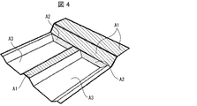
- FIG. 4 is a diagram showing a portion of the lower mold 1 that acts on the reinforcing fiber base material in the preform manufacturing process.
- a flat reinforcing fiber base material or a reinforcing fiber base material impregnated with a matrix resin composition is placed on the lower mold 1 of the preform type.
- the "reinforcing fiber base material or the reinforcing fiber base material impregnated with the matrix resin composition” is also referred to as "(resin-impregnated) reinforcing fiber base material”.
- the reinforcing fiber base material is, for example, a unidirectional material or a unidirectional prepreg. This unidirectional material or unidirectional prepreg is used as a laminated body in which fiber directions intersect each other. By intersecting the fiber directions, the obtained preform is less likely to crack and the handleability is good.
- the reinforcing fiber base material impregnated with the matrix resin composition may be heated on the lower mold 1 within a range effective for softening the matrix resin composition contained in the reinforcing fiber base material.
- the temperature of the reinforcing fiber base material during heating can be appropriately determined according to the type of the reinforcing fiber base material according to the purpose of softening. For example, when the matrix resin composition in the reinforcing fiber base material contains a thermosetting resin, depending on the combination of the resin and the curing agent, from the viewpoint of softening the reinforcing fiber base material without proceeding the thermosetting reaction.
- the temperature of the reinforcing fiber base material impregnated with the matrix resin composition during heating may be 40 to 100°C, and more preferably 50 to 80°C.
- Heating of the (fiber-impregnated) reinforced fiber base material can be performed using a known heating device.
- the heating device is preferably a device capable of heating the (fiber-impregnated) reinforced fiber base material in a short time.
- the infrared heater can usually heat the reinforcing fiber base material to the above temperature by heating for about 30 seconds and can sufficiently soften the (resin-impregnated) reinforcing fiber base material.
- the lower mold 1 has the function of cooling the heated (softened) (resin-impregnated) reinforced fiber base material. Therefore, it becomes easier to collect from the lower mold 1 the reinforced fiber base material that has been softened and further deformed according to the shape of the lower mold (resin impregnation).
- the (resin-impregnated) reinforced fiber base material is arranged in a shape that does not excessively protrude from the lower mold 1 of the preform mold during shaping. Further, the (resin-impregnated) reinforced fiber base material may appropriately have a notch for enhancing the followability to the lower die of the preform mold during shaping.
- a portion of the reinforcing fiber base material (the above-mentioned top surface portion 22, the upper portion 21b and the top surface portion 11c) corresponding to the fixing portion A1 of the lower die 1 of the preform type is fixed to the fixing portion A1 such as a heat resistant adhesive tape.
- this fixing may be fixing utilizing the tackiness of the reinforcing fiber base material, or may be fixing by vacuum suction.
- the reinforcing fiber base material (resin-impregnated) fixed to the lower die 1 of the preform type by the fixing portion A1 as described above is pressed toward the compression deformation portion A2 (the lower portion 21a described above).
- the bottom portion 10a (10b) of the (resin-impregnated) reinforced fiber base material is different because the length of the top surface portion 11c in the longitudinal direction is different from the length of the lower portion 21a and the lower portion 10a (10b) in the longitudinal direction. It is for the purpose of assisting the corresponding portion to be drawn toward the lower portion 21a. As a result, shear deformation occurs in the wall portion 11a.
- this pressing can be performed, for example, by moving a part of the upper mold corresponding to the lower mold 1 corresponding to the compression deformation portion A2 toward the lower mold 1 and pressing it. If it is possible to pull in the base material while causing shear deformation, another portion, for example, the pressing portion A3 may be pressed toward the bottom portions 10a and 10b. Other pressing devices may be used. Further, from the viewpoint of enhancing the followability of the reinforcing fiber base material to the compression deformation portion A2, the reinforcing fiber base material may be pressed toward the lower portion 21a via the elastic member.
- the pressing may be performed so that the (resin-impregnated) reinforced fiber base material deforms within the range of the deformation amount and comes into contact with the compression deformation portion A2.
- the pressing on the compressive deformation portion A2 may be performed at a speed of 10 to 150 mm/sec, and the prepreg (the resin-impregnated reinforced fiber base material) may be pressed at a temperature of 50 to 100° C.
- the pressing force to the compression deforming portion A2 may be 0.005 to 0.05 MPa, preferably 0.02 to 0.03 MPa.
- the pressing time may be such that the prepreg is sufficiently cooled and the mold can be opened.
- the fixed part A1 is located higher than the compression deformation part A2. Therefore, in the case of pressing with the upper die, the fixed portion A1 is located at a shallower position and the compression deformation portion A2 is located at a deeper position in the advancing direction (pushing direction) of the upper die.
- the reinforcing fiber base material undergoes shear deformation toward the front stage portion 20 side at the portions corresponding to the wall portions 11a and 11b with the portion fixed at the top surface portion 11c as the fixed end.
- the compression deformation portion A2 is pressed, in the compression deformation portion A2 (the lower portion 21a) sandwiched between the inclined wall portion 11a (11b) and the wall portion 12a (13a), the reinforcing fiber base material is sheared and deformed. It deforms by compression. In this way, both the shear deformation and the compression deformation can be generated in the reinforcing fiber base material by pressing the compression deformation portion A2.
- the pressing part A3 (a part of the reinforcing fiber base material that is not fixed or pressed) is pressed toward the lower mold 1 of the preform mold.
- This pressing can be performed by moving the upper mold toward the lower mold 1 of the preform mold and fitting the mold.
- the reinforcing fiber base material is pressed against the entire surface of the lower mold 1 of the preform mold, and shaped into the shape of the inner surface of the lower mold of the preform mold.
- the pressing force applied to the entire surface of the lower mold 1 of the preform mold may be 0.005 to 0.05 MPa, preferably 0.02 to 0.03 MPa, and the pressing time is such that the prepreg is sufficiently cooled and It is good as long as it can be opened.
- the pressing of the entire preform lower mold 1 need not be performed when the reinforcing fiber base material is sufficiently shaped by pressing the compression deformation portion A2. Further, the pressing of the entire preform lower mold 1 may be performed again after the pressing of the compression deformation portion A2 is once released. For example, to press the entire surface of the lower mold 1 of the preform mold, the reinforcing fiber base material pressed to the compression deformation portion A2 is once removed from the lower mold 1 of the preform mold, and then the pressed reinforcing fiber base material is pressed. It may be carried out after the preform type lower mold 1 is installed again.
- the planar reinforcing fiber base material is pressed against the lower mold 1 of the preform mold to cause at least a part of the reinforcing fiber base material to undergo shear deformation and compression deformation, thereby Shape into a three-dimensional shape.
- a preform in which the shape of the inner surface of the preform lower mold 1 is transferred to the reinforcing fiber base material is manufactured.
- the part of the (resin-impregnated) reinforced fiber base material that contacts the fixed part A1 is fixed.
- the portion of the reinforcing fiber base material corresponding to the fixed portion A1 is the end portion of or adjacent to the subsequent shear deformation, or the end portion of or adjacent to the compression deformation, as described above.
- the fixed (resin-impregnated) reinforced fiber base material is pressed toward the compression deformation portion A2.
- the force in the out-of-plane direction is applied to the portion of the (resin-impregnated) reinforced fiber base material where the amount of compression deformation is relatively large.
- the (resin-impregnated) reinforced fiber base material does not cause floating in a portion corresponding to a complicated three-dimensional shape in which shear deformation and compression deformation can occur at the same time during shaping, and wrinkles are substantially generated. It is shaped without causing it.
- the compression deformation portion A2 is located at a lower position than the fixed portion A1, and when expressed by unevenness, it can be said that the compression deformation portion A2 is a concave portion and the fixed portion A1 is a protrusion portion.
- the fixed portion A1 corresponding to the protrusion first and the compression deformation portion A2 corresponding to the recess afterward shearing/compressive deformation is caused in the recess located around the protrusion.
- the reinforcing fiber base material is shaped into a predetermined shape, and wrinkles are prevented from being formed on the shaped (resin-impregnated) reinforcing fiber base material.
- the (resin-impregnated) reinforced fiber base material is pressed against the entire lower mold 1 of the preform mold after being pressed against the compression deformation portion A2. Therefore, the (resin-impregnated) reinforced fiber substrate more sufficiently follows the lower mold and is more sufficiently shaped.
- the lower die 1 of the preform mold has, for example, a bottom portion 10a including at least one corner portion 31 and a wall portion 11a standing upright from an edge of the bottom portion 10a when seen in a plan view. 21 and 21 are included.
- the corner portion 31 is formed by a first side 41 and a second side 42. Therefore, when the flat reinforcing fiber base material is pressed into the lower mold 1 to be shaped, both the deformation due to shearing and the deformation due to compression occur in the reinforcing fiber base material at the time of pressing. For example, if shear deformation occurs in the wall portion 11a, compression deformation occurs in the wall portion 21 (lower portion 21a) located ahead of the shear deformation. Therefore, in the production of the preform using the lower mold 1 including the above structure, the above-described effect of suppressing the generation of wrinkles can be more significantly exhibited.
- the wrinkle generation suppressing effect can be more remarkably exhibited in the production of the preform. That is, the bottom 10a (10b) has a further corner 32 (34) different from the corner 31 (33) and a third corner different from the first side 41 (51) and the second side 42 (52). And a side 43 (53). Further, the further corner portion 32 (34) is formed by the second side 42 (52) and the third side 43 (53), and the lower mold 1 stands upright from the third side 43 (53).
- the wall portion 12a (13a) is further included.
- the wall portion of the lower die 1 of the preform type has an inclined surface forming an obtuse angle with the inner surfaces of the bottom portions 10a and 10b. Therefore, in the lower portion 21a, the compressive deformation of the reinforcing fiber base material becomes larger toward the bottom side. Therefore, in the production of the preform, the above-mentioned effect of suppressing the generation of wrinkles is more remarkably exhibited.
- a unidirectional material or a unidirectional prepreg is used for the reinforcing fiber base material, so that a larger deformation of the reinforcing fiber base material is possible.
- the reinforcing fiber base material may be a cloth material, a cloth prepreg and/or a prepreg sheet, and regardless of which reinforcing fiber base material is used, a composite material molded article having desired mechanical properties can be produced with high productivity. It is possible to
- deformation may be required in an amount exceeding the amount of deformation of the reinforcing fiber base material.
- the compressive deformation portion A2 when the compressive deformation portion A2 is pressed, the shear deformation exceeding the amount of deformation of the reinforcing fiber base material with respect to the portion of the reinforcing fiber base material that undergoes shear deformation, such as a portion in contact with the walls 11a and 11b. You may go.
- out-of-plane deformation can be induced in a portion having a sufficiently small amount of deformation in the peripheral portion of the portion of the reinforcing fiber base material that undergoes shear deformation or compression deformation.
- the amount of deformation in the peripheral portion becomes large, while the amount of deformation in the portion that undergoes large shear deformation or compression deformation is substantially within the range of the amount of deformation of the reinforcing fiber base material. Therefore, a sufficiently good preform can be manufactured even if a reinforcing fiber base material having a deformation amount less than the deformation amount required from the shape of the preform to be manufactured is used.
- the preform manufactured in this embodiment is suitably used as a material for a composite material molded product in manufacturing the composite material molded product.
- the method for manufacturing a composite material molded product according to the present embodiment includes a step of manufacturing a preform by the method of manufacturing a preform according to the present embodiment described above, and a step of manufacturing a composite material molded product by heating and pressing the preform.
- Including and The method for producing a composite material molded product according to the present embodiment can be carried out in the same manner as a known method for a composite material molded product, except that the preform of the present embodiment is used as the preform.
- the step of heating and pressurizing the preform can be performed as follows.
- the temperature of the mold depends on the matrix resin composition used or the combination of the matrix resin composition and the curing agent, but is preferably 100 to 170°C, more preferably 130 to 150°C.
- the temperatures of the upper mold and the lower mold of the mold may be the same or different, but are preferably the same.
- the surface pressure of the mold during molding is preferably 1 to 15 MPa, more preferably 4 to 10 MPa.
- the mold referred to herein may be a preform mold if possible, but is, for example, a mold for molding.
- the preform is cured or solidified by heating and pressurizing the preform to cure or soften it and then cooling it.
- the molding time is preferably 1 to 15 minutes, more preferably 2 to 5 minutes.
- the above molding time can be appropriately determined based on the productivity required for the composite material molded product and the selection of the material for realizing it. For example, by appropriately selecting a matrix resin composition containing a thermosetting resin for automobile products, it is possible to produce a composite material molded product for automobile products by the above heating and pressing for 150 to 600 seconds. Is.
- the preform is cured by heating and pressurization, so that wrinkles and meandering of the reinforcing fiber at the time of molding are suppressed.
- the composite material molded article has almost no portion for cutting the reinforcing fiber bundle, and the integrity is maintained. Therefore, by the manufacturing method according to the present embodiment, it is possible to manufacture a composite material molded product having a good appearance and desired mechanical properties. Since the manufacturing method according to the present embodiment does not require at least cutting for preliminarily dividing the reinforcing fiber base material, it is superior in productivity to the conventional manufacturing method that requires such division.
- a composite material molded article may be manufactured from the reinforcing fiber base material containing the matrix resin composition without using the above-mentioned preform. That is, the method for manufacturing the composite material molded article in the present embodiment includes the above-described first step and second step, and after heating and pressing the reinforcing fiber base material to which the force in the out-of-plane direction is applied. A molding step of manufacturing a composite material molded article by cooling may be further included.
- each step in the manufacturing method can be carried out in the same range as the above-described first step and second step within a range in which a composite material molded product can be manufactured.
- the reinforcing fiber base material impregnated with the matrix resin composition is reinforced with a mold having an appropriate shape and with an appropriate pressing force so as to have the shape of the composite material molded article.
- the fiber base material may be pressed.
- the above-mentioned molding step may be carried out in the same manner as the above-mentioned "step of manufacturing the composite material molded article by heating and pressurizing the preform".
- the reinforcing fiber base material impregnated with the matrix resin composition fixed in the mold is heated and heated at a temperature and a sufficient time for producing a composite material molded article from the reinforcing fiber base material. Just press.
- a method for directly manufacturing a composite material molded article from such (resin-impregnated) reinforced fiber base material, and a molding method similar to the preform mold is used by a manufacturing method that does not use a preform. It is possible to produce composite material moldings which have a good appearance and the desired mechanical properties.
- the manufacturing method of such a composite material molded article can be performed, for example, in the same manner as the above-mentioned manufacturing method of the preform using the preform mold.
- the manufacturing method since the manufacturing method does not require at least cutting for dividing the reinforcing fiber base material, the manufacturing method is excellent in productivity as compared with the conventional manufacturing method that requires such division. Further, in the manufacturing method, since the production of the preform is omitted, it is possible to omit the work for producing the composite material molded article from the preform, and thus the workability is excellent.
- the preform or the composite material molded product according to the present embodiment can be suitably manufactured by using a mold described below.
- the mold of this embodiment has an upper mold and a lower mold.
- the upper mold and the lower mold may be installed so as to be above and below in the gravity direction, or may be installed vertically or tilted. In that case, either one of the two molds fitted to each other is referred to as an upper mold.
- the mold should be installed so as to open and close in the direction of gravity so that the matrix resin composition does not become deficient due to gravity in addition to the above flow. Is preferred.
- the upper mold and the lower mold are fitted with each other to form an internal space having a shape substantially the same as the shape of the molded product. At least one of the upper mold and the lower mold has a recess for forming the internal space.
- the divided mold is a mold that is divided into a plurality of parts and that each of the divided parts is movable.
- the split mold is, for example, configured to be capable of advancing and retracting in the opposing direction of the upper mold and the lower mold.
- the upper mold may be a split mold, the lower mold may be a split mold, or both may be split molds.
- the mold of the present embodiment has at least two mechanisms for moving the split mold. These two mechanisms are also called the first mechanism and the second mechanism.
- the first mechanism is a mechanism for fixing a predetermined part of the reinforcing fiber base material to a lower mold on a part of the split mold.
- the predetermined portion is a part of the plurality of split molds, an end portion of a portion of the planar reinforcing fiber base material containing reinforcing fibers to undergo shear deformation and/or compression deformation, and a portion adjacent to the portion. At least one of them.
- the first mechanism can be constructed by using a device capable of advancing a part of the split mold toward the lower mold. For example, a predetermined split mold and the split mold facing the lower mold. It is constructed by an actuator for advancing and retreating (in the out-of-plane direction of the reinforcing fiber base material). Examples of actuators include power cylinders, and examples of power cylinders include air cylinders and hydraulic cylinders.
- the second mechanism is a mechanism that causes another part of the split type to apply a force in the out-of-plane direction of the reinforcing fiber base material to the portion of the reinforcing fiber base material that undergoes shear deformation and/or compression deformation.
- the second mechanism can be constructed by a predetermined split mold and an actuator that advances and retracts the split mold toward the lower mold.
- the mold Since the mold has the above-mentioned configuration, it is possible to perform the above-mentioned first step and second step. From the viewpoint of carrying out the above-described manufacturing method, the mold may further include a configuration other than the above, and may have a further function, as long as the effects of the present embodiment can be obtained.
- the split mold may further have a third mechanism for moving another part of the multiple split molds in the in-plane direction of the reinforcing fiber base material.
- the third mechanism is a mechanism capable of performing the movement assisting process described above. That is, the third mechanism is, for example, when a part of the reinforcing fiber base material is deformed in the out-of-plane direction, and the peripheral part moves toward the part in the in-plane direction, the surface of the peripheral part. Assist such movement in the inward direction.
- examples of the third mechanism include a mechanism for moving the split mold and the second mechanism in the direction in which the reinforcing fiber base material in the mold moves in the in-plane direction.
- the "direction in which the reinforcing fiber base material moves in the in-plane direction" can be appropriately determined depending on the shape of the mold and the fixed portion.
- the “direction in which the reinforcing fiber base material moves in the in-plane direction” can be uniquely determined if the direction in which the reinforcing fiber base material deforms in the in-plane direction is one direction.
- the deforming direction is a plurality of directions, all of the plurality of directions may be used.
- the deforming direction may be a part of the plurality of directions depending on the amount of deformation of the reinforcing fiber base material in the in-plane direction.
- the amount of movement of the second mechanism in the in-plane direction by the third mechanism can be appropriately determined according to the amount of deformation of the portion that deforms in the out-of-plane direction and the width of its peripheral portion.
- the amount of movement of the second mechanism in the in-plane direction by the third mechanism may be the amount of movement of the peripheral portion that sufficiently suppresses the occurrence of wrinkles during molding in the portion that deforms in the out-of-plane direction.
- the movement amount of the peripheral portion tends to be larger when the deformation amount of the portion deformed in the out-of-plane direction is larger, and smaller when the deformation amount is smaller.
- the example of the third mechanism includes a mechanism for moving another part of the plurality of split molds along a rail extending in the in-plane direction.
- the mechanism can perform the movement of the reinforcing fiber base in the in-plane direction independently of deforming another part of the reinforcing fiber base in the out-of-plane direction.
- the direction in which the rail extends can be appropriately determined from the direction that allows the split die to move in the desired direction, and may be in-plane or out-of-plane. Alternatively, it may be a direction oblique to the in-plane direction.
- the function of the third mechanism described above may be further provided to the second mechanism described above.
- the second mechanism may be capable of advancing and retreating further in the in-plane direction.
- the power cylinder described above as the second mechanism is arranged so as to be inclined so as to advance and retreat in both the out-of-plane direction and the in-plane direction of the reinforcing fiber base material. Is included.
- the above power cylinder can advance and retreat the split type in the out-of-plane direction as well as advance and retract the split type in a specific direction and distance in the in-plane direction.
- the moving direction of the split mold in the in-plane direction by the power cylinder can be determined by, for example, orienting the axial direction of the power cylinder in a desired in-plane direction.
- the amount of movement (movement distance) in the in-plane direction of the split mold by the power cylinder can be controlled by, for example, the tilt angle of the axial direction of the power cylinder with respect to the in-plane direction.
- the second mechanism also serves as the third mechanism makes it possible to expand the functions of the mold with a simpler configuration. Further, according to the configuration, in association with the deformation of the reinforcing fiber base material in the out-of-plane direction by the second mechanism, in the in-plane direction of the reinforcing fiber base material to complement the deformation in the out-of-plane direction. Is carried out. Therefore, it is preferable from the viewpoint of stably producing a higher quality preform or molded composite material.
- the lower mold may also have a split mold like the upper mold.
- the mold may further include any one of the above-described first mechanism, second mechanism, and third mechanism for a part or all of the lower mold halves.
- the configuration in which the lower mold also has the split mold is more preferable from the viewpoint of reliably performing the first step, the second step, and the movement assisting step described above regarding the manufacturing method in manufacturing a preform having a complicated shape. preferable.
- the mold forms an internal space having substantially the same shape as that of the mold for producing the preform for the floor pan for the interior of the automobile described above.
- FIG. 5 is a diagram schematically showing an example of the configuration of the upper split mold in the mold according to the embodiment of the present invention. For the sake of clarity, the state of being turned over is shown.
- FIG. 6 is a diagram schematically showing a state in which the upper split drive unit shown in FIG. 5 is visible.
- a cylinder is shown as an example of the drive unit.
- FIG. 7: is a figure which shows typically an example of a structure of the lower division type
- FIG. 8 is a diagram schematically showing a state in which the split mold drive unit is visible from the lower mold shown in FIG. 7. Similar to FIG. 6, a cylinder is shown as an example of the drive unit.
- the upper split mold 100 includes an upper split mold body 101, an upper split mold first portion (hereinafter, also referred to as “first split mold”) 110, and an upper split mold second portion (hereinafter, referred to as “first split mold”).
- first split mold first portion
- first split mold second portion
- second split mold upper split mold second portion
- the upper split mold main body 101 includes a low portion 102, an inclined portion 103 and a high portion 104 from one end to the other end.
- the direction in which the low portion 102, the inclined portion 103, and the high portion 104 are arranged is also referred to as “length direction”, and the length direction when the upper split mold 100 or the lower split mold 200 is viewed in plan.
- the direction orthogonal to is also referred to as "width direction”.
- the surfaces of the upper split mold 100 and the lower split mold 200 which will be described below, are preferably subjected to a mold release treatment.
- the releasing treatment include releasing tape, coating, and coating with a slip assisting film such as a fluororesin film. Therefore, the surface of each of the upper split mold 100, the lower split mold 200, and the split mold described below has a surface layer having excellent releasability.
- the first split mold 110 is a plate-shaped member that extends in the width direction in the lower portion 102 of the upper split mold body 101.
- the first split mold 110 is made of aluminum, for example.
- the other edge of the first split mold 110 is processed into a shape along the slope of the inclined portion 103.
- the lower portion 102 has a first recess 111 in which the first split mold 110 is housed.
- a first drive portion recess 112 is formed inside the first recess 111, and two power cylinders 113, 113 are arranged in the first drive portion recess 112.
- the power cylinders 113, 113 are, for example, air cylinders.
- the power cylinders 113, 113 are arranged such that the pistons advance and retreat along the vertical direction orthogonal to the plane direction of the upper split mold body 101.
- the first split mold 110 is fixed to the tip of the piston.
- the upper split mold body 101 has a first ridge 121, a second ridge 131, and a third ridge 141 at the high portion 104.
- the first ridge 121 is arranged inside the upper split mold body 101 in the width direction.
- the first ridge 121 has two power cylinders 122, 122.
- the power cylinders 122, 122 are arranged such that their pistons advance and retreat in the vertical direction.
- the second split mold 120 is fixed to the tip of the piston.
- the second split mold 120 is, for example, a plate-shaped member that overlaps the top surface of the first protrusion 121 and is made of aluminum.
- the second ridges 131 are formed along the one side edge of the upper split mold body 101 in the high portion 104, and the third ridges 141 are formed along the other side edge of the upper split mold body 101.
- the second protruding portion 131 and the third protruding portion 141 have two power cylinders 132, 132 and power cylinders 142, 142, respectively.
- the piston is arranged so as to advance and retreat in the vertical direction.
- the third split mold 130 is fixed to the tip of the piston in the second protrusion 131
- the fourth split mold 140 is fixed to the tip of the piston in the third protrusion 141.
- Each of the third split mold 130 and the fourth split mold 140 is a plate-shaped member that overlaps with the top surfaces of the second ridge 131 and the third ridge 141, and is made of aluminum.
- the upper split mold body 101 has a second recess 151 and a third recess 161 in the high portion 104.
- a second drive portion recess 152 is formed in the center of the second recess 151, and two power cylinders 153, 153 are arranged in the second drive portion recess 152.
- the fifth split mold 150 is fixed to the tips of the two power cylinders 153, 153.
- the fifth split mold 150 is, for example, a substantially trapezoidal trapezoidal-shaped member housed in the second recess 151, and is made of aluminum.
- a third drive section recess 162 is formed inside the third recess section 161, and two power cylinders 163 and 163 are arranged in the third drive section recess 162.
- the sixth split mold 160 is fixed to the tips of the two power cylinders 163, 163.
- the sixth split mold 160 is, for example, a substantially trapezoidal trapezoidal-shaped member housed in the third recess 161, and is made of aluminum.
- the surfaces of the first split mold 110 to the sixth split mold 160 when the piston is most retracted are substantially flush with the surface of the upper split mold body 101 in the periphery thereof. ..
- the lower split mold 200 includes a lower split mold body 201, a lower split mold seventh portion (hereinafter, also referred to as “seventh split mold”) 210, and a lower split mold eighth portion (hereinafter, referred to as “seventh split mold”). , And an eighth divided type) 220 and a lower divided type ninth portion (hereinafter, also referred to as a “ninth divided type”) 230.
- the lower split mold main body 201 includes a high portion 202, an inclined portion 203, and a low portion 204 from one end to the other end.
- the high portion 202 corresponds to the top surface portion 22 described above
- the inclined portion 203 corresponds to the wall portion 21 described above
- the low portion 204 corresponds to the corrugated structure 10 described above.
- the seventh split mold 210 is a plate-shaped member that extends in the width direction at the high portion 202 of the lower split mold body 201.
- the seventh split mold 210 is made of aluminum, for example.
- the other end edge of the seventh split mold 210 is cut out along the slope of the inclined portion 203.
- the high portion 202 is formed with a first recess 211 in which the seventh split mold 210 is housed.
- a seventh drive unit recess 212 is formed inside the first recess 211, and two power cylinders 213 and 213 are arranged in the seventh drive unit recess 212.
- the power cylinders 213 and 213 are arranged such that the pistons advance and retreat along a vertical direction orthogonal to the plane direction of the lower split mold main body 201.
- the seventh split mold 210 is fixed to the tip of the piston.
- the lower split mold main body 201 has a first ridge portion 221, a second ridge portion 231 and a third ridge portion 241 in the lower portion 204.
- the first ridge portion 221 is arranged inside the lower split mold main body 201 in the width direction.
- the surface of the first ridge portion 221 is covered with, for example, an aluminum plate.
- the first ridge portion 221 corresponds to the aforementioned ridge portion 11.
- the second ridges 231 are formed along the one side edge of the lower split mold main body 201 in the lower portion 204, and the third ridges 241 are formed along the other side edge of the lower mold split main body 201. Has been formed. Both the surface of the second ridge portion 231 and the surface of the third ridge portion 241 are covered with, for example, an aluminum plate. The second ridge portion 231 and the third ridge portion 241 correspond to the above-mentioned edge portions 12 and 13.
- the lower split main body 201 has a second recess 251 and a third recess 261 in the lower portion 204.
- a second drive portion recess 252 is formed in the center of the second recess 251.
- Two power cylinders 253 and 253 are arranged in the second drive portion recess 252.
- An eighth split mold 220 is fixed to the tips of the two power cylinders 253 and 253.
- the eighth split mold 220 is, for example, a plate-shaped member housed in the second recess 251 and is made of aluminum.
- the second recess 251 and the third recess 261 correspond to the above-mentioned bottoms 10a and 10b.
- a third drive section recess 262 is formed inside the third recess section 261, and two power cylinders 263, 263 are arranged in the third drive section recess 262.
- the ninth split mold 230 is fixed to the tips of the two power cylinders 263 and 263.
- the ninth split mold 230 is, for example, a plate-shaped member housed in the third recess 261 and is made of aluminum.
- the surfaces of the eighth split mold 220 to the ninth split mold 230 when the above-mentioned piston is most advanced are the first projection 221, the second projection 231 and the third projection 231 in the periphery thereof. It is substantially flush with the surface of the portion 241.
- FIG. 9 is a figure which shows typically the principal part at the time of seeing from the side surface of a type
- FIG. 10 is a figure which shows typically the principal part at the time of seeing from the front of a type
- a planar reinforcing fiber base material 500 is arranged on the lower split mold 200 of the preform mold.
- resin films for improving releasability may be attached to both sides of the reinforcing fiber base material 500.
- the seventh split type 210 is in a slightly advanced position.
- the eighth split mold 220 and the ninth split mold 230 are positioned so that their surfaces are at the same height as the surfaces of the first ridges 221, the second ridges 231 and the third ridges 241. ..
- the reinforcing fiber base material 500 includes the seventh split die 210, the inclined portion 203, the eighth split die 220, the ninth split die 230, the first ridge portion 221, and the second ridge portion 221. It is supported by the portion 231 and the third protrusion portion 241.
- the upper split mold 100 is arranged so as to face the lower split mold 200.
- the lower part 102 of the upper split mold 100 and the higher part 202 of the lower split mold 200 face each other, and the inclined part 103 of the upper split mold 100 and the inclined part 203 of the lower split mold 200 face each other, and the height of the upper split mold 100 increases.
- the portion 104 and the lower portion 204 of the lower split mold 200 face each other. Initially, the upper split mold 100 is at a position sufficiently distant from the lower split mold 200. Therefore, it is easy to arrange the reinforcing fiber base material 500 on the lower split mold 200 in the first state.
- the position of each split mold in the upper split mold 100 is not limited.
- the first split mold 110, the second split mold 120, the third split mold 130, and the fourth split mold 140 are all in a slightly advanced position.
- the fifth split mold 150 and the sixth split mold 160 are both in the most retracted position.
- the reinforcing fiber base material 500 is bent in the length direction of the lower split mold 200, but is supported substantially flat in the width direction. Therefore, wrinkles are unlikely to occur in the reinforcing fiber base material 500.
- FIG. 11 is a figure which shows typically the principal part at the time of seeing from the side surface of a type
- FIG. 12 is a figure which shows typically the principal part at the time of seeing from the front of a type
- the upper split mold 100 advances toward the lower split mold 200.
- the first split mold 110, the second split mold 120 and the third split mold 130 of the upper split mold 100 also move toward the lower split mold 200.
- FIG. 13 is a figure which shows typically the principal part at the time of seeing from the side surface of a type
- FIG. 14 is a figure which shows typically the principal part at the time of seeing from the front of a type
- the upper split mold 100 advances toward the lower split mold 200 up to the position where the first split mold 110 contacts the reinforcing fiber base material 500.
- the first split mold 110 clamps and fixes the portion of the reinforcing fiber base material 500 supported by the seventh split mold 210 together with the seventh split mold 210.
- the second split mold 120, the third split mold 130, and the fourth split mold 140 advance to a position where they come into contact with the reinforcing fiber base material 500.
- the portions of the reinforcing fiber base material 500 supported by the first ridge portion 221, the second ridge portion 231, and the third ridge portion 241 of the lower split mold 200 are the ridge portions.
- the second split mold 120, the third split mold 130, and the fourth split mold 140 respectively.
- the first split mold 110 of the upper split mold 100 to the fourth split mold 140, and the power cylinder for advancing and retreating these are part of the plurality of split molds, and shear deformation and/or Alternatively, it constitutes a first mechanism for fixing the end portion of the portion to be compressed and deformed and the portion adjacent to the portion to the lower split mold 200.
- the fifth split mold 150 and the sixth split mold 160 in the upper split mold 100 advance toward the lower split mold 200 after fixing a part of the reinforcing fiber base material 500 as described above.
- FIG. 15 is a figure which shows typically the principal part at the time of seeing from the side surface of a type
- FIG. 16 is a figure which shows typically the principal part at the time of seeing from the front of a type
- the upper split mold 100 further advances toward the lower split mold 200.
- the first split mold 110 and the seventh split mold 210 are housed in the first recess 111 of the upper split mold 100 and the first recess 211 of the lower split mold 200, respectively.
- the reinforcing fiber base material 500 is sandwiched between the lower portion 102 of the upper split mold 100 and the higher portion 202 of the lower split mold 200. Further, the reinforcing fiber base material 500 is sandwiched between the inclined portion 103 of the upper split mold 100 and the inclined portion 203 of the lower split mold 200.
- the fifth split mold 150 and the sixth split mold 160 are respectively the eighth split mold 220 and the eighth split mold 220 in the reinforcing fiber base material 500. It abuts against the portion supported by each of the ninth split dies 230. Thus, the part is sandwiched by the fifth split mold 150 and the sixth split mold 160, and the eighth split mold 220 and the ninth split mold 230.
- the fifth split mold 150 and the sixth split mold 160 further advance toward the lower split mold 200, and accordingly, the eighth split mold 220 and the ninth split mold 230 retreat.
- the reinforcing fiber base material 500 is further pressed toward the bottom surface of the second recess 251 and the bottom surface of the third recess 261 of the lower split mold 200.
- a force in the out-of-plane direction is applied to the portion of the reinforcing fiber base material 500 adjacent to the portion in contact with the inclined portions 103 and 203 (for example, the portion indicated by reference numeral A2 in FIG. 4).
- the second split mold 120, the third split mold 130, and the fourth split mold 140 retreat, respectively.
- the reinforcing fiber base material 500 is sandwiched between the high portion 104 of the upper split mold 100, the fifth split mold 150 and the sixth split mold 160, and the lower portion 204 of the lower split mold 200.
- the reinforcing fiber base material in the in-plane direction in the side surface portion (for example, the portions indicated by reference numerals 11a and 11b in FIG. 3) of the first protrusion portion 221 of the lower split mold 200, as shown in Examples described later, the reinforcing fiber base material in the in-plane direction.
- the deformation amount of 500 is large.
- a portion of the reinforcing fiber base material 500 to be pressed by the second concave portion 251 and the third concave portion 261 of the lower split mold 200 (a portion indicated by reference numeral A3 in FIG. 4) has, for example, the above-mentioned length. In-plane movement occurs in the in-plane direction toward the inclined portion 203.
- the surfaces of the upper split mold 100 and the lower split mold 200 are subjected to a mold release treatment with a fluororesin film or the like, and thus have excellent mold releasability.
- the surface of the reinforcing fiber base material 500 is also covered with the resin film, as described above. Therefore, in the fourth state, the reinforcing fiber base material 500 may be sandwiched between the fifth split mold 150 and the eighth split mold 220, or may be sandwiched between the sixth split mold 160 and the ninth split mold 230. However, it is relatively easy to move in the in-plane direction.
- the reinforcing fiber base material 500 is molded by the upper split mold 100 and the lower split mold 200, and is cured by subsequent heating, and as a result, the above-mentioned floor pan preform is manufactured.
- the movement of the reinforcing fiber base material 500 in the in-plane direction at the time of molding as described above can be assisted by moving the split mold in a desired direction in the in-plane direction as described above.
- the movement of the split mold in the in-plane direction can be performed by, for example, a mechanism that moves the power cylinder along a rail arranged in the drive recess.
- it can be implemented by a mechanism that supports the power cylinder by inclining it toward a desired in-plane direction at a predetermined angle, or by a mechanism that gradually inclines the power cylinder toward the desired in-plane direction. It is feasible. Since the mold has such an additional mechanism, it is possible to further suppress the generation of wrinkles in the reinforcing fiber base material during molding.
- the method for producing a preform according to the present embodiment is such that at least a part of a planar reinforcing fiber base material containing a reinforcing fiber and a matrix resin composition is sheared and/or compression deformed. Then, the reinforcing fiber substrate is shaped into a three-dimensional shape. And the manufacturing method of the said preform WHEREIN: The edge part of the site
- the reinforcing fiber base material has a complicated three-dimensional shape in which shearing and compression can occur at the same time during shaping, without substantially generating wrinkles, and with a smaller number of steps than conventional. It is possible to manufacture. Therefore, it is possible to manufacture a preform which has an excellent appearance, can suppress deterioration of mechanical properties, and is excellent in productivity.
- the present embodiment it is possible to appropriately adjust the production conditions such as the curing rate, or the physical properties such as the strength according to the composition of the matrix resin composition. Therefore, it is even more effective from the viewpoint of producing a preform having appropriate physical properties according to the intended use of the composite material molded article.
- the second step may further include a movement assisting step for assisting in-plane movement of the reinforcing fiber base material caused by shear deformation and/or compression deformation. Including the movement assisting step in the second step is more effective from the viewpoint of suppressing the generation of wrinkles on the reinforcing fiber base material in the deformation of the reinforcing fiber base material in the out-of-plane direction.
- the three-dimensional shape may be a developable surface and/or a three-dimensional curved surface. According to such a configuration, it is more effective from the viewpoint of manufacturing a preform having a good appearance even when shearing and compression occur simultaneously at the time of shaping by a method having excellent productivity.
- the portion that applies the force in the out-of-plane direction in the second step is the portion that undergoes the shear deformation and/or the compressive deformation and that has the largest amount of deformation, and that the relative portion with respect to the peripheral portion.
- One or more parts selected from the group consisting of a part having a large deformation amount, a part having a deformation amount exceeding a certain threshold value, and a part having an average deformation amount value exceeding a certain threshold value in an arbitrary region. Good.
- out-of-plane deformation of the reinforcing fiber base material is induced by performing shear deformation exceeding the maximum deformation amount of the reinforcing fiber base material on the portion to be sheared. May be.
- the present embodiment may further include a third step of pressing the entire reinforcing fiber base material after the second step.
- the reinforcing fiber base material can be made to more sufficiently follow the lower die of the preform die, and deformation of the preform accompanying the production of the composite material molded article is further suppressed. obtain. Therefore, it is even more effective from the viewpoint of producing a composite material molded product having an excellent appearance.
- the lower die of the preform mold has at least the first side (41 (51)), the second side (42 (52)) and one corner portion (31) when viewed in plan. (33)) including a bottom portion (10a (10b)) and a wall portion that stands up from at least the first side and the second side, and the corner portion is formed from the first side and the second side.
- the wall portion is formed and the first wall portion (wall portion 11a (11b)) standing upright from the first side and the second wall portion (wall portion 21 standing upright from the second side. ) And may be included.
- the bottom portion has a further corner portion (32 (34)) different from the above-mentioned corner portion and a third side portion (43 (34 (34)) different from the above-mentioned first side and second side. 53)), the further corner is formed from a second side and a third side, and the aforementioned wall is a third wall (wall 12a (13a) standing upright from the third side. ) May be further included.
- the second wall portion located between the first wall portion and the third wall portion is pressed. Larger compressive deformation occurs in the part. Therefore, in the preform manufacturing method using the preform type lower mold including the above structure, the effect of the present embodiment is more remarkably exhibited.
- the inner surface of the wall portion may be an inclined surface forming an obtuse angle with respect to the inner surface of the bottom portion.
- the reinforcing fiber base material may be used as one sheet or as a stack of two or more sheets. Such a structure is even more effective from the viewpoint of easily exhibiting desired mechanical properties such as strength required for the composite material molded product.
- the reinforcing fiber base material may be a unidirectional prepreg, a cross prepreg and/or a prepreg sheet. Such a configuration is more effective from the viewpoint of producing a composite material molded product having desired mechanical properties with high productivity.
- the method for manufacturing a composite material molded article according to the present embodiment includes a step of manufacturing a preform by the above-described preform manufacturing method, and a step of manufacturing a composite material molded article by heating and pressing the preform. Including. According to such a configuration, even if the composite material molded product has a complicated three-dimensional shape, one reinforcing fiber base material is shaped, and the composite material molded product is manufactured from a preform having a good appearance. It is possible to Therefore, it is possible to realize the production of a composite material molded product which has an excellent appearance, can suppress deterioration of mechanical properties, and is excellent in productivity.
- the manufacturing method of the composite material molded article according to the present embodiment the first step and the second step described above, the composite material by heating and pressurizing the reinforcing fiber base material to which the force in the out-of-plane direction is applied. And a molding step of manufacturing a molded article.
- This configuration is much more effective from the viewpoint of increasing production efficiency, as compared with the above-described manufacturing method using preforms.
- the mold according to the present embodiment has an upper mold and a lower mold, and one or both of the upper mold and the lower mold are composed of a split mold that is movable by being divided into a plurality of molds.
- the said mold WHEREIN At least the end of the part which carries out shear deformation and/or compression deformation in the planar reinforced fiber base material containing a reinforced fiber in a part of several division type
- the split mold of the present embodiment may further have a third mechanism for moving another part of the split molds in the in-plane direction of the reinforcing fiber base material. This configuration is even more effective from the viewpoint of suppressing the generation of wrinkles due to the deformation of the reinforcing fiber base material in the out-of-plane direction.
- the third mechanism may be a mechanism that moves another part of the plurality of split dies along a rail extending in the in-plane direction.
- the movement of the reinforcing fiber base material in the in-plane direction by the third mechanism can be independently performed against the deformation of the reinforcing fiber base material in the out-of-plane direction by the second mechanism. Is.
- This configuration is even more effective from the viewpoint of precisely moving the reinforcing fiber base material in the in-plane direction by the third mechanism.
- the second mechanism may be a power cylinder (for example, 113) that causes another part of the plurality of split dies to advance and retreat in the out-of-plane direction. This configuration is even more effective from the viewpoint of easily constructing the second mechanism.
- the power cylinder may be arranged so as to be inclined so as to advance and retreat in both the out-of-plane direction and the in-plane direction of the reinforcing fiber base material. This configuration is more effective from the viewpoint of stably producing a high-quality preform or a composite material molded product because the second mechanism also has the third mechanism.
- the bagging film corresponds to the elastic sheet described above.
- “PVC satin film” manufactured by Okamoto Co., Ltd. (trade name, 0.2T ⁇ 50 m ⁇ 1370 mW, manufactured by PVC) was used.
- the breather is a non-woven fabric for forming a gas vent layer during consolidation.
- "A3000-4 Breather level 10" (trade name) manufactured by Richmond Aircraft Products was used.
- the protective film of the prepreg on the breather side was not peeled off during consolidation, and the breather was placed on the prepregs that were stacked via the protective film.
- a sample S of a prepreg laminate 1 having a size of 26 cm ⁇ 26 cm as shown in FIG. 1 was prepared.
- the portion of each side of the sample S having a length of 5 cm is a holding portion by a jig.
- the planar shape of the sample S is rectangular. Further, any two opposite sides of the sample S are along the fiber direction in the prepreg laminate 1.
- the sample S is provided with a rectangular pattern Cu in a grid pattern.
- the angle ( ⁇ 1) of one corner in the pattern Cu is 90° in each case.
- the pattern Cu is a square having a side of 2 cm.
- Each of the two opposite sides of the sample S was clamped by a jig. Then, under an environment of room temperature (25° C.) and humidity of 45%, one jig was moved at a speed of 2 to 8 cm/sec in a direction parallel to the opposite side. The sample S was visually observed, and the size of one corner ( ⁇ 2) of the rectangular pattern Cu when the sample was wrinkled due to the shearing was measured. Then, the difference (absolute value) between ⁇ 1 and ⁇ 2 was obtained and used as the deformation amount of the prepreg laminate 1.
- the prepreg laminate 1 did not have wrinkles even at a deformation amount of 54°. In this way, it was confirmed that the deformation amount of the prepreg laminate 1 was more than 54°.
- the prepreg laminate 1 was changed to a cross prepreg (product name "TR3523 361GMP", manufactured by Mitsubishi Chemical Corporation), and the deformation test was performed.
- the cloth prepreg has a twill weave design in which the reinforcing fiber bundles are orthogonal to each other. Therefore, the cross prepreg was evaluated as a single layer without being laminated.
- the deformation amount of the cross prepreg was 17°.
- Example 1 A cavity as shown in FIG. 3 was used as a lower mold, and the prepreg laminate 1 was placed on the lower mold. Next, the prepreg laminate 1 was fixed to the fixing portion A1 as described above. Next, the fixed prepreg laminated body 1 was pressed against the compression deformation portion A2 and brought into contact therewith. Next, the upper mold was advanced toward the lower mold, and the prepreg laminate 1 was pressed by the upper mold toward the entire lower mold. In this way, the reinforcing fiber base material 1 was shaped to manufacture the preform 1.
- Example 2 A preform 2 was produced in the same manner as in Example 1 except that a cross prepreg was used instead of the prepreg laminate 1.
- Preform C1 was produced in the same manner as in Example 1 except that the preform C1 was not fixed to the fixing portion.
- a preform C2 was produced in the same manner as in Example 1 except that the whole prepreg laminate 1 was pressed toward the lower mold without being pressed against the compression deformation part after being fixed to the fixing part.
- Example 3 A preform C3 was manufactured in the same manner as in Example 1 except that the whole prepreg laminate 1 was pressed toward the lower mold without performing fixing to the fixing part and pressing to the compression deformation part.
- Mold followability A Reinforcing fiber base material sufficiently follows the preform mold even in the details of the preform mold B: In the details of the preform mold, the reinforcing fiber base material is from the preform mold Although it floats, there is no problem in practical use. C: The follow-up of the reinforcing fiber base material to the preform mold is insufficient, which is a practical problem.
- Table 1 shows the evaluation results.
- Both of the preforms 1 and 2 have a good appearance in which the generation of wrinkles is sufficiently suppressed and are well shaped. This is because the reinforcing fiber base material impregnated with the matrix resin composition is sufficiently deformed, and the compression deformation portion is pressed to press the twist of the reinforcing fiber base material impregnated with the matrix resin composition in the compression deformation portion. It is considered that this is because the occurrence of wrinkles in the compressed and deformed portion was prevented.
- the preforms C1 to C3 had wrinkles that caused practical problems. It is considered that this is because a large twist of the reinforcing fiber base material occurred in at least one of the shear-deformable portion and the compressive-deformable portion, resulting in wrinkles.
- FIG. 17 is a plan view of the lower mold used in the examples.
- a preform 1A was manufactured in the same manner as in Example 1 using the reinforcing fiber base material 1 impregnated with the matrix resin composition having the above-mentioned grid pattern. Then, the amount of deformation in each pattern of the preform 1A was obtained. Similarly, a preform 2A was manufactured in the same manner as in Example 1 using the reinforcing fiber base material 2 impregnated with the matrix resin composition having a grid pattern, and the amount of deformation in each pattern was obtained.
- FIG. 18 is a diagram showing the amount of deformation of the main part of the preform of the embodiment.
- (a) is a diagram showing the amount of deformation of the portion of the preform 1A indicated by the symbol E in FIG. 18B is a diagram showing the amount of deformation of the portion of the preform 2A indicated by the symbol E in FIG.
- the numerical values in FIG. 18 are the difference between ⁇ 1 and ⁇ 2 (the value of ⁇ 2- ⁇ 1) at the upper right corner with respect to the paper surface of each pattern.
- both the reinforcing fiber base materials 1 and 2 impregnated with the matrix resin composition are largely deformed at the wall portion 11b and the lower portion 21a.
- the reinforcing fiber base material 1 impregnated with the matrix resin composition is deformed at a deformation amount of more than 20° in the wall portion 11b and less than 20° in the lower portion 21a, Deformation is substantially suppressed at the bottom portion 10b and the upper portion 21b. Since the deformation amount of the reinforcing fiber base material 1 impregnated with the matrix resin composition is more than 54°, according to (a) of FIG. 18, the reinforcing fiber base material 1 is formed in the portion corresponding to the wall portion 11b and the lower portion 21a. Is sufficiently deformed and follows the wall portion 11b and the lower portion 21a.
- the deformation amount of the reinforcing fiber base material 2 is 17°. Therefore, as shown in (b) of FIG. 18, in the reinforcing fiber base material 2, the deformation amount in the wall portion 11b and the lower portion 21a is suppressed to about 17°. On the other hand, the amount of deformation at the bottom portion 10b and the upper portion 21b is larger than that of the reinforcing fiber base material 1. As described above, in the reinforcing fiber base material 2, the out-of-plane deformation occurs also in the peripheral portion of the portion that is greatly deformed. Therefore, in the reinforced fiber base material 2, the portion that requires large deformation and the peripheral portion that does not require substantial deformation are deformed to sufficiently deform the wall portion 11b and the lower portion 21a. I know what I did.
- Example 3 The preform 1 is housed in a molding die, heated and pressed at 140° C. and 4 MPa for 5 minutes, cooled to room temperature, and the obtained molded article is removed from the die to have a shape as shown in FIG. A composite material molded product 1 which is to be a floor pan laid inside a car was manufactured.
- FIG. 19 is a diagram for explaining the dimensions of the floor pan manufactured in the example.
- the arrows X, Y and Z are orthogonal to each other.
- the arrow X indicates a direction traversing the corrugated structure in the plane shape of the floor pan
- the arrow Y indicates a direction along the longitudinal direction of the corrugated structure.
- the arrow Z indicates the height direction of the corrugated structure.
- L1 is a line segment extending along the Y direction on the surface of the top surface portion of the corrugated structure.
- L2 is a line segment that extends along the Y direction on the surface of the bottom of the corrugated structure.
- L3 is a line segment that extends along the X direction on the surface of the inclined portion.
- L4 is a line segment that extends along the X direction on the surfaces of the top surface, the wall, and the bottom of the corrugated structure.
- hc indicates a distance in the Z direction between the top surface portion and the bottom portion in the corrugated structure (height from the bottom portion to the top surface portion).
- L1 has a length of 520 mm
- L2 has a length of 548 mm
- L3 has a length of 440 mm
- L4 has a length of 530 mm.
- the shortest distance between L1 and L2 is 40 mm
- the shortest distance between L3 and L4 is 30 mm.
- As is 35° and hc is 82.5 mm.
- Example 4 and Comparative Example 5 Composite material molded products 2 and C4 were obtained in the same manner as in Example 3 except that Preform 2 and Preform C4 were used instead of Preform 1.
- the manufacturing method of the example for manufacturing a preform having such an excellent appearance does not include at least the following three steps, and can be manufactured in a smaller number of steps as compared with the conventional method. Therefore, it is clear that the manufacturing method of the embodiment is superior to the conventional one in productivity. -Cutting and laminating process of reinforcing fiber base material to form partial preform-Partial preform assembly process-Assembled partial preform pressure bonding process.
- each of the preforms C1 to C3 was so large that wrinkles and twists were practically problematic, and therefore, composite material molded products were not manufactured.
- the present invention can be applied to the production of a composite material molded product having a complicated shape, which has been difficult to mold from a reinforcing fiber base material impregnated with a single sheet-shaped matrix resin composition.
- INDUSTRIAL APPLICABILITY The present invention is particularly suitable for manufacturing members such as automobile parts, which are required to have both good appearance and mechanical properties.
Landscapes
- Engineering & Computer Science (AREA)
- Mechanical Engineering (AREA)
- Chemical & Material Sciences (AREA)
- Composite Materials (AREA)
- Textile Engineering (AREA)
- Casting Or Compression Moulding Of Plastics Or The Like (AREA)
- Moulding By Coating Moulds (AREA)
Abstract
優れた外観を有するとともに機械的特性の低下を抑制可能であり、かつ生産性に優れる複合材料成形品の製造を実現する。一方向材のシートを下型の特定の部位に固定し、当該シートのせん断変形または圧縮変形する部位の特定の部分に面外方向の力を与えて、当該シートが賦形されてなるプリフォームを得る。当該プリフォームを型で加熱加圧して所望の形状を有する複合材料成形品を得る。
Description
本発明は、プリフォームの製造方法および複合材料成形品の製造方法ならびに型に関する。
強化繊維含む強化繊維基材にマトリックス樹脂を含浸させ、硬化させた複合材料成形品は、一般に、軽量で優れた機械特性を有する。このため、スポーツ、航空宇宙、一般産業などの種々の分野において様々な用途に広く用いられている。
当該強化繊維基材は、通常、平面状(シート状)であり、前述の硬化の前に、複合材料成形品の形状またはそれに近い形状に賦形してプリフォームを経る方法が知られている。当該プリフォームをさらに圧縮成形することにより複合材料成形品が製造される。当該プリフォームの製造方法には、複数の部分プリフォームを作製し、それらの接合端部で互いに接合させて、複合材料成形品に対応する一体のプリフォームを製造する方法が知られている(例えば、特許文献1参照)。
上記の製造方法は、部分プリフォームを接合してプリフォームを製造することから、複雑な形状を有する複合材料成形品であっても、プリフォームにおけるシワの発生を十分に抑制することが可能であり、優れた外観を有する複合材料成形品を製造することができる。
しかしながら、上記の製造方法では、部分プリフォームを接合してプリフォームを製造することから、強化繊維基材を一体的に賦形してなるプリフォームから製造された複合材料成形品に比べて、例えば接合部分における強度が低くなることがある。
また、上記の製造方法では、部分プリフォームを接合してプリフォームを製造することから、そのための種々の工程を実施する必要がある。たとえば、部分プリフォームが互いに並べられるように、また厚み方向で適切に重なり合うように、強化繊維基材を切断する必要がある。また、作製した部分プリフォームを互いに接合させる必要がある。このように、上記の製造方法は、複合材料成形品の機械的特性および生産性の観点から検討の余地が残されている。
本発明の一態様は、優れた外観を有するとともに機械的特性の低下を抑制可能であり、かつ生産性に優れる複合材料成形品の製造を実現することを目的とする。
上記の課題を解決するために、本発明の一態様に係るプリフォームの製造方法は、強化繊維およびマトリックス樹脂組成物を含む平面状の強化繊維基材の少なくとも一部をせん断変形および/または圧縮変形させて、前記強化繊維基材を三次元形状に賦型するプリフォームの製造方法であって、前記強化繊維基材におけるせん断変形および/または圧縮変形させる部位の端部、ならびに、前記部位に隣接する部分、のうち少なくとも一ヶ所をプリフォーム型に対して固定する第一の工程と、前記端部および/または前記部分を固定した後に、前記せん断変形および/または圧縮変形させる部位に面外方向の力を与える第二の工程と、含む。
また、上記の課題を解決するために、本発明の一態様に係る複合材料成形品の製造方法は、上記のプリフォームの製造方法でプリフォームを製造する工程と、プリフォームを加熱加圧して複合材料成形品を製造する工程と、を含む。
また、上記の課題を解決するために、本発明の一態様に係る複合材料成形品の製造方法は、強化繊維およびマトリックス樹脂組成物を含む平面状の強化繊維基材の少なくとも一部をせん断変形および/または圧縮変形させて複合材料成形品を製造する複合材料成形品の製造方法であって、前記強化繊維基材におけるせん断変形および/または圧縮変形させる部位の端部、ならびに、前記部位に隣接する部分、のうち少なくとも一ヶ所を成形型に対して固定する第一の工程と、前記端部および/または前記部分を固定した後に、前記せん断変形および/または圧縮変形させる部位に面外方向の力を与える第二の工程と、前記面外方向の力を与えられている前記強化繊維基材を加熱加圧して複合材料成形品を製造する成形工程と、を含んでもよい。
また、上記の課題を解決するために、本発明の一態様に係る型は、上型と下型とを有する型であって、前記上型および前記下型の一方または両方は、複数に分割して移動可能な分割型で構成され、複数の分割型の一部に、強化繊維を含む平面状の強化繊維基材におけるせん断変形及び/または圧縮変形させる部位の端部、ならびに、前記部位に隣接する部分、のうち少なくとも一ヶ所を前記下型に対して固定させる第一の機構と、複数の分割型の別の一部に、前記せん断変形及び/または圧縮変形させる部位へ、前記強化繊維基材の面外方向の力を与えさせる第二の機構と、を有する。
本発明の一態様によれば、優れた外観を有するとともに機械的特性の低下を抑制可能であり、かつ生産性に優れる複合材料成形品の製造を実現することができる。
〔プリフォームの製造方法〕
本発明の一実施の形態に係るプリフォームの製造方法は、強化繊維基材をプリフォーム型に対して押圧して、強化繊維基材の少なくとも一部をせん断変形および/または圧縮変形させて強化繊維基材を三次元形状に賦型する。なお、本明細書中「Aおよび/またはB」は、「AおよびBの一方または両方」を意味する。
本発明の一実施の形態に係るプリフォームの製造方法は、強化繊維基材をプリフォーム型に対して押圧して、強化繊維基材の少なくとも一部をせん断変形および/または圧縮変形させて強化繊維基材を三次元形状に賦型する。なお、本明細書中「Aおよび/またはB」は、「AおよびBの一方または両方」を意味する。
強化繊維基材は、平面状の形状を有する。すなわち強化繊維基材は、平面方向への広がりを有する。平面状の強化繊維基材とは、例えば、強化繊維基材のシートである。強化繊維基材は、平面状である範囲において、プリフォームおよび複合材料成形品の製造に使用可能な公知の基材から適宜に選ぶことが可能である。強化繊維基材については後に詳述する。
プリフォーム型は、強化繊維基材の賦形に利用可能な範囲において適宜に決めることが可能である。プリフォーム型については、図面を用いて後に詳述する。
強化繊維基材は、三次元形状に賦形される。三次元形状とは、立体的な形状であることを示し、平面、可展面および三次元曲面のうち、いずれか一つ、または二つ以上の組み合わせ、からなる。可展面とは、伸縮させることなく、展開することにより平面になる面を示す。可展面の一例としては、錐面が挙げられる。
三次元曲面とは、平面を伸縮させずに形成することができない面のことを示し、展開して平面とすることができない面を示す。三次元曲面の一例としては、球面が挙げられる。
賦形すべき形状が可展面および/または三次元形状で構成される場合では、せん断、圧縮およびそれらの両方を含む複雑な変形を賦形時に生じるため、本実施形態におけるプリフォームの製造方法の優位性がより顕著になりやすい。
二次元の平面状のシート部材を、当該三次元形状を形成するための型に追従するように押圧すると、賦形時にせん断変形が生じる。賦形時に、元のシート部材の面積に対して、追従させる面の面積が小さい場合は、同時に圧縮変形が生じる。本実施形態において、強化繊維基材は、その少なくとも一部がせん断変形により、および/または、圧縮変形により、またはこれらの両方により変形することで賦形される。強化繊維基材が賦形されることによりプリフォームが製造される。また、本実施形態によれば、せん断変形が生じる三次元形状に対して賦形を行った場合でも、外観が良好なプリフォームを得ることができる。また、せん断変形に加え、圧縮変形が生じる場合であっても、外観が良好なプリフォームを得ることができる。
本実施形態における強化繊維基材の賦形は、より具体的には、以下の第一の工程と第二の工程とを含む。
[第一の工程]
第一の工程とは、強化繊維基材におけるせん断変形および/または圧縮変形させる部位の端部または当該部位に隣接する部分をプリフォーム型に対して固定する工程である。
第一の工程とは、強化繊維基材におけるせん断変形および/または圧縮変形させる部位の端部または当該部位に隣接する部分をプリフォーム型に対して固定する工程である。
第一の工程における「せん断変形および/または圧縮変形させる部位」(以下、「せん断/圧縮変形対象部位」とも言う)とは、強化繊維基材の少なくとも一部分である。たとえば、後述の第二の工程によってせん断変形する部位、および、第二の工程によって圧縮変形する部位、のうち少なくとも一ヶ所である。せん断/圧縮変形対象部位は、賦型すべき形状に応じて決められる。賦形すべき形状とは、複合材料成形品の形状、または、そのためのプリフォームとして実現すべき当該複合材料成形品の形状に近い形状、である。
ここで、第一の工程で固定する強化繊維基材の部分は、せん断/圧縮変形対象部位の端部、または、せん断/圧縮変形対象部位に隣接する部分、またはその両方、である。せん断/圧縮変形対象部位の端部とは、せん断/圧縮変形対象部位の中ではあるが、内部ではなく縁にある部分のことをいう。せん断/圧縮変形対象部位に隣接する部分とは、せん断/圧縮変形対象部位の外側にあり、せん断/圧縮変形対象部位から離れない部分のことをいう。当該部分は、例えば、せん断変形の始点になり得るし、または圧縮変形する部分を規定する固定端になり得る。たとえば、第一の工程で強化繊維基材の固定された部分の縁に沿う方向に強化繊維基材が引っ張られる場合には、せん断変形が生じる。また、第一の工程で強化繊維基材の固定された部分は実質的には変形しないので、その周辺で強化繊維基材の面積が小さくなるように変形される場合には、圧縮変形が生じる。
プリフォーム型に強化繊維基材を固定して賦形したときに、当該強化繊維基材の部分にかかる力の向きは予測可能である。よって、上記の固定を伴う賦形で強化繊維基材にせん断変形および圧縮変形が生じる部分も予測可能である。第一の工程で強化繊維基材において固定する部分は、プリフォーム型の形状に応じて適宜に決めることが可能である。
たとえば、第一の工程で固定する部分は、平面で構成される部分(例えば前述した平面または可展面)であることが、シワの発生を抑制する観点から好ましい。また、第一の工程で固定する部分は、プリフォーム型の下型のうち、最も高さが高い部分であることが上記の観点から好ましい。ここで、上記の二方向には、強化繊維基材が長繊維を引き揃えたものである場合、強化繊維基材における繊維軸方向(「配向方向」とも言う)が含まれていることが好ましい。さらに、第一の工程で固定する部分が複数箇所存在する場合では、より高い部分から順に固定することが、シワの発生を抑制する観点から好ましい。また、第一の工程で固定する部分は、下型の中央部に高さが高い部分がある場合、下型の一端部および中央部の一方または両方を含むことが、賦形時における強化繊維基材の追従性を高める観点から好ましい。
第一の工程における「固定」とは、強化繊維基材の固定されるべき部分がプリフォーム型に対して相対的に、実質的には移動しないことを意味する。たとえば、強化繊維基材における第一の工程で固定されている部分は、面外方向および面内方向のいずれにも移動しなくてもよいし、第二の工程においてせん断/圧縮変形が十分に実現される範囲において移動してもよい。面内方向とは、この場合、平面上の強化繊維基材を含む平面内の水平方向を示し、面外方向とは、前記面内方向に直交する方向を意味する。
なお、「固定」の代わりに、強化繊維基材を押さえた部分を、強化繊維基材が滑りにより移動しうるよう仮押さえにしてもよい。仮押さえの場合は、強化繊維基材が伸張性に乏しい場合、押圧した部分の周辺から型の内部に向かって強化繊維基材が引き込まれるため、賦形後の端部が揃わないことが多い。そのため、賦形後に、賦形すべき形状になるようトリミングが必要になる。そのため、仮押さえよりも固定が好ましい。
このような強化繊維基材の一部をプリフォーム型に対して固定する方法は、強化繊維基材の構成をさらに考慮して適宜に決めることが可能である。当該方法の例には、強化繊維基材以外の接着部材によって強化繊維基材をプリフォーム型に接着して固定する方法、強化繊維基材が有する粘着性を利用して強化繊維基材をプリフォーム型に対して固定する方法、および、真空脱気による固定、が含まれる。
接着による固定における接着部材の例には、粘着剤層を有する耐熱テープおよび接着剤が含まれる。接着剤は、強化繊維基材に含浸したマトリックス樹脂と同種の樹脂であってもよいし、別の種類の樹脂であってもよいし、これらの両方を含んでいてもよい。また、前述の粘着剤層を構成する粘着剤であってもよい。
粘着性を利用する固定の例には、加熱による固定、および、加圧による固定、が含まれる。
加熱による固定は、例えば強化繊維基材が後述するマトリックス樹脂組成物をさらに含有する場合に、加熱によって強化繊維基材から染み出るマトリックス樹脂組成物の粘着性によって強化繊維基材をプリフォーム型に相対的に固定させる方法である。加熱による固定における温度および時間などの加熱条件は、当該粘着性による十分な接着強度が得られる範囲において適宜に決めることができる。
加圧による固定は、加圧によって強化繊維基材から染み出るマトリックス樹脂組成物の粘着性によって強化繊維基材をプリフォーム型に相対的に固定させる方法である。圧力などの加圧条件も、加熱による固定と同様に、当該粘着性による十分な接着強度が得られる範囲において適宜に決めることができる。
真空脱気による固定は、固定すべき範囲において強化繊維基材およびプリフォーム型を気密に覆い、この覆われた部分を脱気して十分に減圧することにより、気密に覆われた部分においてプリフォーム型に対して強化繊維基材を固定する方法である。減圧度などの真空脱気の条件は、減圧により十分な固定の強さが得られる範囲において適宜に決めることができる。
第一の工程により、固定された強化繊維基材がその後にプリフォーム型の(下型と上型との)嵌合により押圧された場合の、当該強化繊維基材におけるせん断変形を生じる部分および圧縮変形を生じる部分が規定される。
[第二の工程]
第二の工程は、上記の第一の工程後に、せん断/圧縮変形対象部位に面外方向の力を与える工程である。第二の工程において、面外方向の力を印加する部分は、せん断/圧縮変形対象部位の全部であってもよいが、プリフォームにおけるシワの発生を実質的に防止可能な範囲において、せん断/圧縮変形対象部位の一部分であってもよい。
第二の工程は、上記の第一の工程後に、せん断/圧縮変形対象部位に面外方向の力を与える工程である。第二の工程において、面外方向の力を印加する部分は、せん断/圧縮変形対象部位の全部であってもよいが、プリフォームにおけるシワの発生を実質的に防止可能な範囲において、せん断/圧縮変形対象部位の一部分であってもよい。
面外方向の力を与えるべきせん断/圧縮変形対象部位の一部分は、プリフォームにおけるシワの発生を実質的に防止可能な範囲において、適宜に決めることが可能である。たとえば、第二の工程において面外方向の力を与えるせん断/圧縮変形対象部位の一部分の例には、せん断/圧縮変形対象部位のうちの、最も変形量が大きい部分、その周辺部に対して相対的に大きな変形量を有する部分、変形量がある閾値を超える部分、および、任意の領域における変形量の平均値がある閾値を超える部分、が含まれる。
面外方向の力を与える部分は、せん断変形を生じる部分であってもよいし、圧縮変形を生じる部分であってもよいし、それらに隣接する部分であってもよい。面外方向の力を与える部分が圧縮変形を生じる部分であることは、圧縮による浮きを抑える観点で、プリフォームにおけるシワの発生をより効果的に防止する観点から好ましい。面外方向の力を与える部分がせん断変形を生じる部分に隣接する部分であることは、せん断変形を生じる部分の一端を固定していることから、他端に面外方向の力を与えることになる。このため、効率的にせん断変形を生じさせることができるという観点から好ましい。
ここで、強化繊維基材における変形量は、以下の方法によって測定することが可能である。図1は、強化繊維基材の変形量を測定するための強化繊維基材の試料を模式的に示す図である。図2は、図1の試料における碁盤目状の模様の、当該試料のせん断変形前後の形状を模式的に示す図である。
まず、図1に示すような碁盤目状の模様Cuを有する強化繊維基材の試料Sを用意する。試料Sの平面形状および模様Cuにおける碁盤目のそれぞれの平面形状は、いずれも矩形である。模様Cuの一角度θ1は、図2に示すように、例えば90°である。
次いで、少なくとも試料Sの対向する一対の辺を含む縁部のそれぞれを治具で挟持する。次いで、それぞれの当該治具に、試料Sにせん断力を与える方向の力(例えば図2中で試料Sの下部を固定した場合の矢印Fに示す方向の力)を印加して試料Sの平面形状を変形させる。すると模様Cuの一角部の角度θ2は、例えば図2に示すように、90°よりも大きくなる。このときの角度θ2を変形量とする。変形量は、元の角度からの変化量が分かるように表されればよく、例えば、角度の絶対値で表してもよいし、元の角度(θ1=90°)からの差またはその絶対値で表してもよい。試料Sにシワが発生する直前の変形量を最大変形量とする。
また、上記碁盤目状の模様を有する強化繊維基材をプリフォームの形状に賦形することにより、プリフォームの形状に賦形したときの強化繊維基材の部分的な変形量の大きさが求められる。こうして求められる変形量の大きい部分のうちの任意の部分を、第二の工程において面外方向の力を印加すべき部分に決めてもよい。
第二の工程における面外方向の力は、強化繊維基材の平面内に直交する方向の力を意味する。本発明においては、プリフォーム型の下型に向けて強化繊維基材を押圧する方向の力を示す。当該面外方向の力は、種々の方法によって、強化繊維基材における所定の部分に与えることが可能である。たとえば、面外方向の力は、プリフォーム型の下型に向けて強化繊維基材を押圧するための上型による押圧によって、上記の所定の部分に与えることが可能である。あるいは、面外方向の力は、プリフォーム型の下型において上記の所定の部分に対応する部分に強化繊維基材を押圧するための押圧用の部材で押圧することによって、上記の所定の部分に与えることが可能である。当該押圧用の部材には、例えば、下型における上記の対応する平面形状を有する弾性部材(例えば、発泡ポリエチレン製の部材など)を用いることも可能である。
第二の工程では、せん断/圧縮変形対象部位に対して、強化繊維基材の変形量を超えたせん断変形を行うことで強化繊維基材の面外変形を誘起することが可能である。すなわち、プリフォームの形状で要求される変形量よりも小さい変形量を有する強化繊維基材を第二の工程においてせん断/圧縮変形させてもよい。この場合、強化繊維基材において面外方向の力が与えられる部分は、まず、強化繊維基材の変形量まで変形する。強化繊維基材の変形量を超えてせん断力/圧縮力が与えられた場合、前記強化繊維基材にシワが発生する。すなわち、面外方向への変形が生じる。この状態で面外方向へ押圧すると、前記強化繊維基材を面外方向へさらに変形させることができる。これに加えて、強化繊維基材におけるせん断/圧縮変形対象部位の周辺部(例えば前述した平面または可展面)も面外変形し、それにより、面外方向の力が与えられる部分での強化繊維基材の変形の不足分が補われることもある。よって、このような強化繊維基材の変形量の補完が可能な範囲において、本実施形態では、プリフォームの形状で要求される変形量に満たない変形量を有する強化繊維基材を適用することが可能である。
第一の工程および第二の工程による段階的な押圧では、第一の工程における押圧すべき位置が押し込み方向においてより浅い位置にあり、第二の工程で押圧すべき位置がより深い位置にあることが好ましい。これは、シワを発生させないように、強化繊維基材の自重およびドレープ性を利用しながら強化繊維基材にせん断および圧縮を発生させる観点から好ましい。
また、第二の工程において、面外方向の力が与えられる強化繊維基材は、平面上で直交する二軸で規定される四方位のうちの多くとも三方位で固定されていることが好ましい。この場合、面外方向の力が与えられた強化繊維基材は、上記の四方位のうちの少なくとも一方位側に自由端を有する。したがって、型に対してある一方向を規定した場合に、当該方向に対して型に沿った長さが異なる部分があると、伸長しにくい強化繊維基材を用いた場合、面外方向の力が与えられたときに強化繊維基材の一部が型に引き込まれる。すなわち、面内方向の移動が生じる。そうした場合に、当該自由端側から強化繊維基材が面内方向において移動しやすい。したがって、プリプレグおよび複合材料成形品におけるシワの発生を抑制する観点から好ましい。
[その他の工程]
本実施形態に係るプリフォームの製造方法は、本実施形態の効果が得られる範囲において、前述した第一および第二の工程以外の他の工程をさらに含んでいてもよい。たとえば、当該プリフォームの製造方法は、第二の工程において、移動補助工程をさらに含んでもよい。
本実施形態に係るプリフォームの製造方法は、本実施形態の効果が得られる範囲において、前述した第一および第二の工程以外の他の工程をさらに含んでいてもよい。たとえば、当該プリフォームの製造方法は、第二の工程において、移動補助工程をさらに含んでもよい。
移動補助工程は、せん断変形及び/または圧縮変形に伴って生じる強化繊維基材の面内方向の移動を補助する工程である。面外方向へ力をかけることにより生ずるせん断変形及び/または圧縮変形においては、強化繊維基材を予め型に対して固定している。このため、変形量が段階的に変化する部位がある場合では、当該変形に伴って、強化繊維基材には面内方向に段階的に移動する部分も生じる。この面内方向への移動が不十分であると、それを補完するため、別の部位でシワが生じることがある。
移動補助工程は、基材の変形度が相対的に大きい部分の変形を補助するため、基材の変形度が相対的に大きい部分、または当該部分に隣接する部分が、面内方向において、強化繊維基材の予め固定した部分へ向かって移動することを補助する。移動補助工程は、強化繊維基材を面内方向に積極的に移動させることによって実施することが可能である。たとえば、型について後述する第三の機構を用いて実施することが可能である。
移動補助工程では、当該型に対する強化繊維基材の滑り性を高めることが、面内方向への移動を円滑に実行し、シワの発生を抑制する観点から好ましい。当該滑り性は、例えば、強化繊維基材における面内方向へ移動させたい部分に対応する型の表面をフッ素樹脂層のような離型性に優れる層を付与することによって高めることが可能である。あるいは、上記の滑り性は、型に当接する強化繊維基材の表面を保護フィルムなどの被覆材で覆うことによって高めることが可能である。
移動補助工程は、せん断変形及び/または圧縮変形させる部位へ面外方向の力を与えること、と、それによる強化繊維基材の面内方向への移動を補助すること、とを独立して行ってもよい。その両方を同時に行うことは、強化繊維基材でのシワの発生を抑制する観点から好ましい。
また、当該プリフォームの製造方法は、第二の工程の後に強化繊維基材の全体を押圧する第三の工程をさらに含んでもよい。
(第三の工程)
第三の工程は、プリフォーム型の下型に対応する上型で強化繊維基材を押圧することによって実行することが可能である。あるいは、第三の工程は、第一の工程で強化繊維基材が固定され、第二の工程で面外方向の力が与えられて変形している場合には、これらの押圧されている部分以外の強化繊維基材の表面をプリフォーム型の下型に向けて押圧することにより実行することが可能である。第三の工程により、強化繊維基材がより強く賦形され、より良好なプリフォームを製造することが可能となる。
第三の工程は、プリフォーム型の下型に対応する上型で強化繊維基材を押圧することによって実行することが可能である。あるいは、第三の工程は、第一の工程で強化繊維基材が固定され、第二の工程で面外方向の力が与えられて変形している場合には、これらの押圧されている部分以外の強化繊維基材の表面をプリフォーム型の下型に向けて押圧することにより実行することが可能である。第三の工程により、強化繊維基材がより強く賦形され、より良好なプリフォームを製造することが可能となる。
(仮押さえ工程)
本実施形態に係るプリフォームの製造方法は、前述の他の工程として、強化繊維基材を仮押さえする仮押さえ工程をさらに含んでいてもよい。仮押さえ工程は、強化繊維基材の任意の部分に面外方向の力を与えるもので、強化繊維基材を完全に固定しないことで、面内方向への移動を許容する工程である。当該仮押さえ工程は、例えば、上型または上型から突出する他部材によって強化繊維基材を下型に向けて適度な力で押圧することによって実施することが可能である。当該仮押さえ工程は、例えば、強化繊維基材の端部に対して行い、強化繊維基材の賦形時において、強化繊維基材中央部を押圧した場合に、端部が立ち上がることを抑制する。したがって、シワの発生を予防する観点から好ましい。
本実施形態に係るプリフォームの製造方法は、前述の他の工程として、強化繊維基材を仮押さえする仮押さえ工程をさらに含んでいてもよい。仮押さえ工程は、強化繊維基材の任意の部分に面外方向の力を与えるもので、強化繊維基材を完全に固定しないことで、面内方向への移動を許容する工程である。当該仮押さえ工程は、例えば、上型または上型から突出する他部材によって強化繊維基材を下型に向けて適度な力で押圧することによって実施することが可能である。当該仮押さえ工程は、例えば、強化繊維基材の端部に対して行い、強化繊維基材の賦形時において、強化繊維基材中央部を押圧した場合に、端部が立ち上がることを抑制する。したがって、シワの発生を予防する観点から好ましい。
(圧密化工程)
また、本実施形態に係るプリフォームの製造方法は、前述の他の工程として、平面状の強化繊維基材を圧密化する圧密化工程をさらに含んでいてもよい。圧密化工程は、強化繊維基材を複数層積層して使用する場合に、個々の強化繊維基材の接着強度をより高める観点から好ましい。
また、本実施形態に係るプリフォームの製造方法は、前述の他の工程として、平面状の強化繊維基材を圧密化する圧密化工程をさらに含んでいてもよい。圧密化工程は、強化繊維基材を複数層積層して使用する場合に、個々の強化繊維基材の接着強度をより高める観点から好ましい。
圧密化工程は、強化繊維基材に含まれる空気を除去するための工程であり、強化繊維基材を、面外方向に沿って押圧することにより好適に実行することが可能である。強化繊維基材は、一枚、または二枚以上で用いる。クロス材は、製織してあることにより、賦形時にシート形状が崩れることがないことため、単層(一枚)で使用することができる。二枚以上の強化繊維基材を用いる場合は、積層することで積層体として用いる。二枚以上の強化繊維基材を用いる場合は、同形状のものを重ねて使用してもよく、強度や剛性を高めたい部分の形状に切断したものを重ねて使用してもよい。
圧密化工程は、例えば、強化繊維基材を平坦な作業台の上に配置し、その上からゴムシートなどの弾性シートを配置し、当該作業台側から減圧して、弾性シートを強化繊維基材に圧着させることにより実行することができる。上記の減圧を解除して弾性シートと作業台との間の空間の圧力を大気圧に戻すことにより、圧密化された強化繊維基材が得られる。このような圧密化工程を実行することは、二枚以上の強化繊維基材の集合(積層体)の状態を実質的に維持する観点からも効果的である。
(裁断工程)
また、本実施形態に係るプリフォームの製造方法は、前述の他の工程として、平面状の強化繊維基材を所望の形状に裁断する裁断工程をさらに含んでいてもよい。裁断工程は、圧密化前に強化繊維基材を配置する前に、強化繊維基材を所望の形状に切断することにより実行することができる。所望の形状とは、例えば、プリフォーム型に追従した強化繊維基材を平面に投影した形状および/または展開した形状である。裁断工程のより具体的な例には、強化繊維基材の外縁部(余剰分)を切断する工程、および、プリフォーム型への追従に適した切込みを形成する工程、が含まれる。裁断工程は、超音波カッターなどの公知の切断装置を用いて実施してもよく、はさみやカッターなどの通常の切断器具を用いて実施してもよい。裁断工程において切断する対象は、前述した一枚の強化繊維基材や、二枚以上の強化繊維基材を積層した積層体であってもよい。
また、本実施形態に係るプリフォームの製造方法は、前述の他の工程として、平面状の強化繊維基材を所望の形状に裁断する裁断工程をさらに含んでいてもよい。裁断工程は、圧密化前に強化繊維基材を配置する前に、強化繊維基材を所望の形状に切断することにより実行することができる。所望の形状とは、例えば、プリフォーム型に追従した強化繊維基材を平面に投影した形状および/または展開した形状である。裁断工程のより具体的な例には、強化繊維基材の外縁部(余剰分)を切断する工程、および、プリフォーム型への追従に適した切込みを形成する工程、が含まれる。裁断工程は、超音波カッターなどの公知の切断装置を用いて実施してもよく、はさみやカッターなどの通常の切断器具を用いて実施してもよい。裁断工程において切断する対象は、前述した一枚の強化繊維基材や、二枚以上の強化繊維基材を積層した積層体であってもよい。
[強化繊維基材]
強化繊維基材は、強化繊維を含有する。強化繊維基材は、マトリックス樹脂組成物を含浸させたものであってもよい。マトリックス樹脂組成物を含有しない強化繊維基材の例には、織物(斜行織物、三軸織物、三次元織物、円形織物)、組物または編組品、ノンクリンプファブリック、および、簾、が含まれる。
強化繊維基材は、強化繊維を含有する。強化繊維基材は、マトリックス樹脂組成物を含浸させたものであってもよい。マトリックス樹脂組成物を含有しない強化繊維基材の例には、織物(斜行織物、三軸織物、三次元織物、円形織物)、組物または編組品、ノンクリンプファブリック、および、簾、が含まれる。
(強化繊維)
強化繊維には、通常の繊維で強化され得る複合材料に使用される繊維を使用することができる。強化繊維は、一種でもそれ以上でもよく、後述する複合材料成形品の所期の物性などの、最終製品である複合材料成形品の用途に応じて適宜に選択することができる。
強化繊維には、通常の繊維で強化され得る複合材料に使用される繊維を使用することができる。強化繊維は、一種でもそれ以上でもよく、後述する複合材料成形品の所期の物性などの、最終製品である複合材料成形品の用途に応じて適宜に選択することができる。
強化繊維の太さは、フィラメント径で1~20μmの範囲であることが好ましく、より好ましくは3~10μmの範囲である。強化繊維の太さが20μm以下であることは、耐炎化工程や焼成工程における製造効率や、強化繊維の欠陥密度を下げ、強度を高める観点から好ましい。また、強化繊維の太さを1μm以上とすることにより、強化繊維束の生産性を高くすることができ、製造コストを安くすることができる。なお、本明細書における「フィラメント径」とは、それぞれの繊維の断面の等面積円相当直径を意味する。
強化繊維は、一種を用いてもよく、二種以上を併用してもよい。強化繊維の例には、ガラス繊維、炭素繊維、アラミド繊維、高強度ポリエステル繊維、ボロン繊維、アルミナ繊維、窒化珪素繊維およびナイロン繊維が含まれる。なお、炭素繊維には黒鉛繊維も含まれる。
中でも、軽量かつ高強度で高弾性率を有し、耐熱性、耐薬品性にも優れる点から、炭素繊維が好ましい。炭素繊維の種類の例には、ピッチ系、ポリアクリロニトリル(PAN)系およびレーヨン系が含まれ、これらのいずれの種類の炭素繊維であってもよい。炭素繊維の生産性の観点からPAN系炭素繊維がより好ましい。
また、炭素繊維束の収束性の観点、または、複合材料成形品とした際の炭素繊維とマトリックス樹脂との接着性を改善する観点から、当該炭素繊維は、その表面に、所定の官能基を有する物質を0.01~5質量%程度有していてもよい。所定の官能基は、一種でもそれ以上でもよく、その例には、エポキシ基、水酸基、アミノ基、カルボキシル基、カルボン酸無水物基、アクリレート基およびメタクリレート基が含まれる。
炭素繊維は、高強度炭素繊維であることが、複合材料成形品の強度を高める観点から好ましい。高強度炭素繊維とは、そのストランド引張強度が4GPa以上、好ましくは4.6GPa以上であり、その引張伸度が1.5%以上である炭素繊維である。ストランド引張強度および引張伸度は、JIS R7608(2007)に基づいて行うストランド引張試験で測定される。
平面状の強化繊維基材を形成するために、強化繊維は、通常、シート状またはテープ状となるように用いられる。なお、便宜上、比較的幅が広いものをシート状と言い、比較的幅が狭いものをテープ状と称する。
強化繊維基材の形態としては、強化繊維を一方向に引き揃えた形態(例えば一方向材)、連続繊維を製織した織物形態(例えばクロス材)、および不織布の形態などが挙げられる。強化繊維基材の十分に高い変形量を発現させられ、連続繊維であることにより、得られる成形品の強度が高いという観点から、一方向材の形態であることが好ましい。
一方向材の例には、強化繊維を一方向に配向させた一方向材、および、一方向に強化繊維を配置してステッチングした一方向性織物、が含まれる。一方向性織物とは、強化繊維を一方向に配向させるとともに補助糸等によりステッチングしたものである。
クロス材の例には、二方向性織物、および三軸織物が含まれる。二方向性織物の例には、平織、朱子織および綾織が含まれる。せん断変形に優れている観点から、クロス材は、二方向性織物である平織、綾織、および朱子織のいずれかであることが好ましい。
強化繊維の使用形態における厚さは、限定されないが、プリフォームにおいて賦形された形状を十分に維持する観点から、例えばシート状の形態であれば0.03mm以上であることが好ましい。当該厚さは、上記の観点から、0.1mm以上であることがより好ましく、0.2mm以上であることがさらに好ましい。また、当該厚さは、強化繊維基材の賦形性を十分に高めてプリフォームおよび複合材料成形品におけるシワの発生を十分に低減させる観点から、4mm以下であることが好ましく、2mm以下であることがより好ましく、1mm以下であることがさらに好ましい。
(マトリックス樹脂組成物)
マトリックス樹脂組成物は、マトリックス樹脂を含有する。マトリックス樹脂は、限定されず、その例には、熱可塑性樹脂および熱硬化性樹脂が含まれる。マトリックス樹脂は、加熱後冷却することにより、固化または硬化して複合材料成形品中に存在する場合において、荷重を強化繊維に伝達する機能を有する。また、強化繊維基材において連続する樹脂相を構成する樹脂である。マトリックス樹脂は、一種でもそれ以上でもよい。
マトリックス樹脂組成物は、マトリックス樹脂を含有する。マトリックス樹脂は、限定されず、その例には、熱可塑性樹脂および熱硬化性樹脂が含まれる。マトリックス樹脂は、加熱後冷却することにより、固化または硬化して複合材料成形品中に存在する場合において、荷重を強化繊維に伝達する機能を有する。また、強化繊維基材において連続する樹脂相を構成する樹脂である。マトリックス樹脂は、一種でもそれ以上でもよい。
熱可塑性樹脂は、加熱により粘度の高い液体状態になって、外力により自由に変形でき、冷却して外力を除去すると、固化して固体状態になり、その形状を保つ。また、この過程を繰り返し行える。マトリックス樹脂として用いられる熱可塑性樹脂は、成形品としての機械特性を大きく低下させない範囲で通常の熱可塑性樹脂の中から適宜に選択することができる。
熱可塑性樹脂としては、例えば、ポリエチレン樹脂、ポリプロピレン樹脂等のポリオレフィン系樹脂、ナイロン6樹脂、ナイロン6,6樹脂等のポリアミド系樹脂、ポリエチレンテレフタレート樹脂、ポリブチレンテレフタレート樹脂等のポリエステル系樹脂、ポリフェニレンサルファイド樹脂、ポリエーテルケトン樹脂、ポリエーテルスルフォン樹脂、芳香族ポリアミド樹脂等を用いることができる。中でも、物性や価格の観点で、ポリアミド樹脂、ポリプロピレン樹脂、ポリフェニレンサルファイド樹脂のいずれかであることが好ましい。これらは、1種を単独で用いてもよく、2種以上を併用してもよい。
熱硬化性樹脂は、熱または触媒の作用を受けて、分子間架橋による硬化反応が進行し、不溶不融の三次元網目構造をとる反応性ポリマーである。マトリックス樹脂として用いられる熱硬化性樹脂は、成形品としての機械特性を大きく低下させない範囲で、通常の熱硬化性樹脂の中から適宜に選択することができる。
熱硬化性樹脂としては、例えば、エポキシ樹脂、不飽和ポリエステル樹脂、アクリル樹脂、ビニルエステル樹脂、フェノール樹脂、フェノキシ樹脂、アルキド樹脂、ウレタン樹脂、マレイミド樹脂、シアネート樹脂、ベンゾオキサジン樹脂、エポキシアクリレート樹脂、ウレタンアクリレート樹脂等が挙げられる。熱硬化性樹脂としては、これらの中から1種以上を適宜選択して使用することができるが、中でも硬化後の強度を高くできる傾向にあることから、エポキシ樹脂が好ましい。
強化繊維基材におけるマトリックス樹脂の含有量は、強化繊維基材においてマトリックス樹脂による連続相が十分に形成される範囲において、適宜に決めることが可能である。当該含有量は、強化繊維基材におけるボイドを低減させる観点から、20質量%以上であることが好ましく、25質量%以上であることがより好ましい。また、当該含有量は、強化繊維基材の機械的物性を十分に高める観点、および、強化繊維基材における適切なタック性の発現の観点から、45質量%以下であることが好ましく、40質量%以下であることがより好ましい。
マトリックス樹脂組成物は、本実施形態の効果を奏する範囲において、前述したマトリックス樹脂以外の他の成分をさらに含有していてもよい。マトリックス樹脂組成物における他の成分の含有量は、本実施形態の効果とともに他の成分を含有することの効果が得られる範囲において、適宜に決めることができる。当該他の成分は、マトリックス樹脂の種類に応じて適宜に決めてもよく、一種でもそれ以上でもよい。上記他の成分の例には、硬化剤、硬化助剤、離型剤、脱泡剤、紫外線吸収剤および充填剤が含まれる。
たとえば、硬化剤は、マトリックス樹脂としての熱硬化性樹脂の硬化反応を進行させ得る成分である。熱硬化性樹脂としてエポキシ樹脂を用いる場合、硬化剤は、硬化後の物性が高いことから、アミン系の硬化剤が好ましい。当該アミン系の硬化剤は、アミノ基を有する化合物または分解によりアミノ基を有する化合物を生じる。また、熱硬化性樹脂がエポキシ樹脂である場合では、硬化速度を高める観点から、硬化剤としてイミダゾール環を有するイミダゾール化合物を使用してもよく、硬化助剤としてウレア基を有するウレア化合物を当該硬化剤に併用してもよい。イミダゾール化合物は、硬化助剤として用いることもできる。
マトリックス樹脂組成物は、当該組成物中の成分の種類および量によって、硬化後における種々の物性を発現させることが可能である。たとえば、熱硬化性樹脂の種類と硬化剤の種類との組み合わせを適切に選択することによって、マトリックス樹脂組成物に高い速硬性を付与することが可能である。このようなマトリックス樹脂を含むプリフォームから製造された複合材料成形品は、高い生産性で製造可能であり、かつ前述したように外観および強度が十分である、よって、自動車部材用の用途に有利である。車内に面し、あるいは車内を仕切るための内装部材や、自動車骨格部品あるいは足回り品などの構造部材である。
(強化繊維基材の具体的な形態)
強化繊維基材は、本実施形態の効果を奏する範囲において、公知の強化繊維基材の中から適宜に選択することができる。
強化繊維基材は、本実施形態の効果を奏する範囲において、公知の強化繊維基材の中から適宜に選択することができる。
当該強化繊維基材の形態としては、シート状の強化繊維基材、テープ状の強化繊維基材複数のテープ状の強化繊維基材を並べたシート状の基材が含まれる。シート状の強化繊維基材の例には、一方向材およびクロス材が含まれる。
強化繊維基材は、それに含浸しているマトリックス樹脂組成物を含んでいてもよい。マトリックス樹脂組成物は、強化繊維間の応力を伝達する役割を担う。マトリックス樹脂組成物が存在することにより、強化繊維同士が接着されるため、変形は抑制されるが、強化繊維基材に与えたせん断力が強化繊維に伝達されることによって変形させることができるため、強化繊維の局所的な蛇行を抑制しながら滑らかな変形を可能にする観点で好ましい。マトリックス樹脂組成物を含む強化繊維基材を用いる場合、本発明の効果を最大限に享受することができる。
前記強化繊維基材に樹脂を含浸させたものとしては、一方向材およびクロス材にマトリックス樹脂組成物を含浸させた一方向性プリプレグおよびクロスプリプレグが例示される。テープ状の強化繊維基材に樹脂を含浸させたものの例には、スリットテープおよびトウプリプレグが含まれる。本実施形態における強化繊維基材には、一方向材、クロス材、一方向性プリプレグ、クロスプリプレグ、およびテープ状の強化繊維基材を並べて形成したシート状基材のいずれも好適に用いることができる。
強化繊維基材の形態は、上記以外の形態であってもよい。上記以外の形態とは、例えば不織布の形態である。このような他の形態の強化繊維基材にマトリックス樹脂組成物を含浸させた強化繊維基材、異なる形態の強化繊維を用いる以外は、一方向性プリプレグの製法と同様の方法によって製造することが可能である。強化繊維基材は、一種を用いてもよく、それ以上を併用してもよい。
<一方向材>
一方向材は、一方向に引き揃えた強化繊維を示す。一方向材を補助糸等により織物の形態に保持したものを一方向性織物とする。取り扱い性の観点から、一方向性織物を用いることが好ましい。
一方向材は、一方向に引き揃えた強化繊維を示す。一方向材を補助糸等により織物の形態に保持したものを一方向性織物とする。取り扱い性の観点から、一方向性織物を用いることが好ましい。
<一方向性プリプレグ>
一方向性プリプレグは、一方向材と、それに含浸しているマトリックス樹脂組成物とによって構成される。また、一方向材は、テープ状であってもよいし、シート状であってもよい。また、シート状の一方向材を、強化繊維に沿う方向に切断してテープ状に加工し、スリットテープを製造してもよい。
一方向性プリプレグは、一方向材と、それに含浸しているマトリックス樹脂組成物とによって構成される。また、一方向材は、テープ状であってもよいし、シート状であってもよい。また、シート状の一方向材を、強化繊維に沿う方向に切断してテープ状に加工し、スリットテープを製造してもよい。
一方向性プリプレグは、公知の方法によって製造することができ、例えば、ホットメルト法によって製造することが可能である。ホットメルト法は、フィルム化されたマトリックス樹脂組成物を一方向に配向させた強化繊維の束に貼り付け、それを加熱加圧して当該マトリックス樹脂組成物を強化繊維束に含浸させる方法である。
なお、本明細書では、一方向性テープを、強化繊維の配向方向が交差するように重ねた積層型のプリプレグシートも、「一方向材(シート)」とも言う。たとえば、本明細書では、テープ状の一方向材を、強化繊維の配向方向を揃えて並べて一方向性の層を形成し、当該一方向性の層を、互いの層の当該配向方向が交差(例えば直交)するように重ねてなる二層以上の積層型プリプレグシートも、一方向材シートと言う。
<クロス材>
クロス材は、強化繊維を繊維材料に含む織物である。当該織物の例には、一方向性織物、二方向性織物、三軸織およびノンクリンプ織物が含まれる。一方向性織物は、必要な方向に強化繊維を配置した織物である。二方向性織物の例には、平織、朱子織および綾織が含まれる。当該織物は、せん断変形に優れている点で、平織、綾織または朱子織であることが好ましい。
クロス材は、強化繊維を繊維材料に含む織物である。当該織物の例には、一方向性織物、二方向性織物、三軸織およびノンクリンプ織物が含まれる。一方向性織物は、必要な方向に強化繊維を配置した織物である。二方向性織物の例には、平織、朱子織および綾織が含まれる。当該織物は、せん断変形に優れている点で、平織、綾織または朱子織であることが好ましい。
<クロスプリプレグ>
クロスプリプレグは、前記のクロス材と、それに含浸しているマトリックス樹脂組成物とによって構成される。当該クロスプリプレグに用いる織物は、せん断変形に優れている点で、平織、綾織または朱子織であることが好ましい。クロスプリプレグは、一方向材の製法と同様の方法によって製造することが可能である。
クロスプリプレグは、前記のクロス材と、それに含浸しているマトリックス樹脂組成物とによって構成される。当該クロスプリプレグに用いる織物は、せん断変形に優れている点で、平織、綾織または朱子織であることが好ましい。クロスプリプレグは、一方向材の製法と同様の方法によって製造することが可能である。
<スリットテープ>
スリットテープは、一方向性プリプレグが強化繊維の配向方向に沿って細長く切断されて形成されたテープ状の強化繊維基材である。スリットテープは、通常、紙管などのボビンに巻き取られる。スリットテープは、一方向性プリプレグを、専用スリッターで短冊状に切断することにより作製することができる。
スリットテープは、一方向性プリプレグが強化繊維の配向方向に沿って細長く切断されて形成されたテープ状の強化繊維基材である。スリットテープは、通常、紙管などのボビンに巻き取られる。スリットテープは、一方向性プリプレグを、専用スリッターで短冊状に切断することにより作製することができる。
<トウプリプレグ>
トウプリプレグは、一方向に配向する強化繊維束とそれに含浸しているマトリックス樹脂組成物とによって構成される。トウプリプレグは、通常、細幅のテープ状の強化繊維基材である。上記の強化繊維束は、例えば、数千~数万本の強化繊維のフィラメント(長繊維)が一方向に配列したものである。
トウプリプレグは、一方向に配向する強化繊維束とそれに含浸しているマトリックス樹脂組成物とによって構成される。トウプリプレグは、通常、細幅のテープ状の強化繊維基材である。上記の強化繊維束は、例えば、数千~数万本の強化繊維のフィラメント(長繊維)が一方向に配列したものである。
トウプリプレグは、マトリックス樹脂組成物を上記の強化繊維束に含浸させることにより製造することができる。強化繊維束へのマトリックス樹脂組成物の含浸は、公知の方法によって行うことが可能である。マトリックス樹脂組成物を強化繊維束に含浸させる方法の例には、レジンバス法、回転ロール法、紙上転写法およびノズル滴下法が含まれる。
レジンバス法は、例えばマトリックス樹脂組成物を貯留しているレジンバス内に強化繊維束(トウ)を通過させてマトリックス樹脂組成物を強化繊維束に含浸させる工程と、オリフィスやロール等によって余剰のマトリックス樹脂組成物を搾り取り、強化繊維束中におけるマトリックス樹脂の含有量を調整する工程とを含む方法である。
回転ロール法は、回転ロール上にマトリックス樹脂組成物の層を形成し、これをトウに転写する方法である。当該回転ロール法の例には、ドクターブレードを有する回転ドラムを当該回転ロールに用いる方法が含まれる。ドクターブレードは、回転ロールへのマトリックス樹脂組成物の付着量を規制し、当該マトリックス樹脂組成物の層の厚さを規定する。
紙上転写法は、紙上にマトリックス樹脂組成物の層を形成し、当該層をトウに転写する方法である。
ノズル滴下法は、特開平09-176346号公報、特開2005-335296号公報および特開2006-063173号公報などの公報に記載されている。
トウプリプレグにおいて、マトリックス樹脂組成物は、複合材料成形品のボイドを低減させる観点、および、複合材料成形品の物性の低下を抑制する観点から、強化繊維束に均一に含浸されていることが好ましい。上記のトウプリプレグの製造方法の中でも、熱硬化性樹脂をマトリックス樹脂とするマトリックス樹脂組成物の供給量の制御や実施の容易さの観点から、回転ロール法が好ましい。
<テープ状の強化繊維基材を並べて形成したシート状の基材>
複数のテープ状の強化繊維基材を並べたシート状の基材は、スリットテープやトウプリプレグを用いて形成する。当該シート状の基材は、複数のテープ状の基材を、テープの長手方向と直交する方向に並べて形成した単位層を構成単位として有する。前記複数のテープ状の強化繊維基材の間の一か所以上に間隙を有する場合、単位層を2層以上積層したものを当該シート状基材とする。単位層を2層以上積層して用いる場合、一方の単位層には前記の間隙がなくても良い。前記複数のテープ同士において、隣り合うテープ状の強化繊維基材がその側縁部で互いに重なるように配置させて用いる場合、単位層を当該シート状基材とする。これらのシート状基材を総称して、プリプレグシートとする。
複数のテープ状の強化繊維基材を並べたシート状の基材は、スリットテープやトウプリプレグを用いて形成する。当該シート状の基材は、複数のテープ状の基材を、テープの長手方向と直交する方向に並べて形成した単位層を構成単位として有する。前記複数のテープ状の強化繊維基材の間の一か所以上に間隙を有する場合、単位層を2層以上積層したものを当該シート状基材とする。単位層を2層以上積層して用いる場合、一方の単位層には前記の間隙がなくても良い。前記複数のテープ同士において、隣り合うテープ状の強化繊維基材がその側縁部で互いに重なるように配置させて用いる場合、単位層を当該シート状基材とする。これらのシート状基材を総称して、プリプレグシートとする。
前記複数のテープ状の強化繊維基材の間の一か所以上に間隙を有する場合、当該間隙の幅は、賦形または成形後の外観上の不良(シワなど)発生を抑制する観点からに適宜に決めることができる。たとえばこのような観点によれば、当該間隙の幅は、隣り合うテープ状の強化繊維基材のどちらか幅が狭い方の幅の0.1~10%の長さであってよい。
前記複数のテープ同士の長手方向の間の一か所以上に間隙を有するプリプレグシートは、例えば、以下の方法によって製造することができる。当該方法とは、例えば、複数のテープ状の強化繊維基材を所定の間隙を有するように並べて単位層を形成する工程と、複数の単位層を、個々の単位層における強化繊維の配向方向が交差する方向となるように重ねる工程とを含む方法である。
隣り合うテープ状の強化繊維基材がその側縁部で互いに重なるように配置されている場合、強化繊維束は、テープ状の強化繊維基材の重なりによる強化繊維束の重なりの位置関係が保たれるように配置する。
隣り合うテープ状の強化繊維基材の重なり長さは、賦形または成形後の外観上の不良(シワなど)発生を抑制する観点および強度に優れる観点からに適宜に決めることができる。たとえばこれらのような観点によれば、上記の重なり長さは、テープ状の強化繊維基材の幅の1~50%の長さであってよい。
隣り合うテープ状の強化繊維基材がその側縁部で互いに重なるように配置されているプリプレグシートは、例えば、以下の方法によって製造することができる。当該方法とは、例えば、複数のテープ状の強化繊維基材をその側縁部において所定の重なり長さで重なり合うように並べて単位層を形成する工程と、複数の単位層を、個々の単位層における強化繊維の配向方向が交差する方向となるように重ねる工程とを含む方法である。
[プリフォーム型]
プリフォーム型は、プリフォームを製造するための型である。すなわち、プリフォーム型は、平面状の強化繊維基材を最終製品である複合材料成形品の形状か、またはそれに近い形状に賦形することが可能な型である。プリフォーム型は、強化繊維基材をプリフォームに賦形可能な範囲において、複合材料成形品を製造するための型と同じであってもよいし、異なっていてもよい。なお、「複合材料成形品に近い形状」とは、複合材料成形品を成形するための型にプリフォームを収容して加熱加圧することが可能な程度に、複合材料成形品の形状に近づけられた形状、とも言える。
プリフォーム型は、プリフォームを製造するための型である。すなわち、プリフォーム型は、平面状の強化繊維基材を最終製品である複合材料成形品の形状か、またはそれに近い形状に賦形することが可能な型である。プリフォーム型は、強化繊維基材をプリフォームに賦形可能な範囲において、複合材料成形品を製造するための型と同じであってもよいし、異なっていてもよい。なお、「複合材料成形品に近い形状」とは、複合材料成形品を成形するための型にプリフォームを収容して加熱加圧することが可能な程度に、複合材料成形品の形状に近づけられた形状、とも言える。
プリフォーム型は、下型と、当該下型に対応する形状を有する上型とを有する通常の型を用いることが可能である。上型および下型は、それぞれ一体であってもよいし、それぞれ複数に分割される構成のものであってもよい。プリフォーム型の上型および下型のいずれにも強化繊維基材を配置して本実施形態に適用することが可能であるが、本実施形態では下型とする。強化繊維基材を型に載置して作業可能であることは、作業性および生産性の観点から好ましい。
プリフォーム型は、前述した第一の工程および第二の工程を、必要に応じてさらに第三の工程を、この順に実行可能なように分割して構成された型であってもよい。たとえば、プリフォーム型は、下型と、強化繊維基材における第一の工程で固定すべき部分を下型に向けて押圧して固定する第一の上型部と、第一の上型部で当該固定すべき部分が固定されている強化繊維基材における、せん断/圧縮変形対象部位のうちの所定の部分を下型に向けて押圧する第二の上型部と、第一の上型部および第二の上型部で押圧されている強化繊維基材におけるそれ以外の部分を下型に向けて押圧する第三の上型部とを有していてもよい。
上記の第一の上型部、第二の上型部および第三の上型部は、この順で強化繊維基材を下型に押圧可能に構成される。これらの上型部は独立して押圧可能に構成されていてもよく、その場合は、手動の操作または自動制御によって上記の順となるように上記上型部は作動する。
[プリフォーム製造方法の具体的態様]
以下、図面を用いてプリフォーム型について、また前述のプリフォームの製造方法をより具体的に説明する。図3は、本実施形態におけるプリフォーム型の下型の構造の一例を模式的に示す図である。以下の説明において、複合材料成形品は、自動車の車内に配置されるフロアパンであり、プリフォームは、当該フロアパン用のプリフォームであり、プリフォーム型は当該プリフォームを製造するための型である。なお、プリフォームおよびフロアパン(複合材料成形品)は、シート状の強化繊維基材を用いることから、下型の内面が転写された形状(当該内面と実質的に同形)となる。
以下、図面を用いてプリフォーム型について、また前述のプリフォームの製造方法をより具体的に説明する。図3は、本実施形態におけるプリフォーム型の下型の構造の一例を模式的に示す図である。以下の説明において、複合材料成形品は、自動車の車内に配置されるフロアパンであり、プリフォームは、当該フロアパン用のプリフォームであり、プリフォーム型は当該プリフォームを製造するための型である。なお、プリフォームおよびフロアパン(複合材料成形品)は、シート状の強化繊維基材を用いることから、下型の内面が転写された形状(当該内面と実質的に同形)となる。
(プリフォーム型の構造)
プリフォーム型は、上型と下型1とを有している。下型1は、コルゲート構造10とその一端側に形成されている前段部20とを有する。
プリフォーム型は、上型と下型1とを有している。下型1は、コルゲート構造10とその一端側に形成されている前段部20とを有する。
コルゲート構造10は、強度を上げるための波状構造である。コルゲート構造10は、底部10a、10bと、これらの底部間に形成されている突条部11と、コルゲート構造10の側縁のそれぞれに形成されている突縁部12、13とを有する。
底部10a、10bは、それぞれ、平面形状が矩形の平面で構成されている。底部10aは、第一の辺41、第二の辺42および第三の辺43を有し、底部10bは、第一の辺51、第二の辺52および第三の辺53を有する。第一の辺41(51)および第三の辺43(53)は、例えば当該矩形における一対の長辺であり、第二の辺42(52)は、例えば当該矩形における一短辺である。
突条部11は、底部10aの一側縁から起立する壁部11aと、底部10bの他側縁から起立する壁部11bと、これらの壁部間に形成されている天面部11cとによって構成されている。壁部11a、11bは、強化繊維基材と接する面が、底部10a、10bが強化繊基材と接する面に対して鈍角をなす傾斜面となっている。天面部11cは、底部10a、10bに水平な平面で構成されている。
突縁部12は、底部10aの他側縁から起立する壁部12aと、壁部12aの上端に形成されている天面部12bとを有する。壁部12aは、強化繊維基材と接する面が、底部10aが強化繊維基材と接する面に対して鈍角をなす傾斜面となっている。天面部12bは、底部10aに水平な平面で構成されている。突縁部13も、突縁部12と同様に壁部13aと天面部13bとを有する。
前段部20は、コルゲート構造10の一端縁から起立する壁部21と、壁部21の上端に形成されている天面部22とを有する。壁部21は、強化繊維基材と接する面が、底部10a、10bが強化繊維基材と接する面に対して鈍角をなす傾斜面となっている。天面部22は、底部10a、10bに水平な平面で構成されている。
底部10a(10b)において、第一の辺41(51)および第二の辺42(52)は角部31(33)を形成しており、第二の辺42(52)および第三の辺43(53)は、角部32(34)を形成している。より詳しくは、底部10a、壁部11a、21の交点には角部31が形成されており、底部10a、壁部12a、21の交点には角部32が形成されている。同様に、底部10b、壁部11b、21の交点には角部33が形成されており、底部10b、壁部13a、21の交点には角部34が形成されている。
天面部11c、12b、13bの底部10a、10bからの高さは、いずれも同じである。天面部22は、他の天面部に比べて高い位置に形成されている。これらの天面部の高さは、製品の仕様によるが、2~40cmであってよい。また、壁部11a、11b、12a、13a、21の底部10a、10bに対する傾斜角も、製品の仕様によるが、30~90°であってよい。なお、壁部21のうち、底部10a、10bから天面部11c、12b、13bまでの高さの部分を下部21a、天面部11c、12b、13bまでの高さよりも上の部分を上部21bとも言う。
このように、プリフォーム型の下型1は、平面視したときに角部31(33)を含む底部10a(10b)と、底部10a(10b)の一側縁(他側縁)から起立する壁部11a(11b)と、底部10a(10b)の一端縁から起立する壁部21(下部21a)とを含んでいる。
また、下型1において、底部10a(10b)は、角部31(33)とは異なるさらなる角部32(34)を含む。壁部21は、底部10a(10b)の一端縁における角部31(33)と角部32(34)との間から起立している。さらに、下型1は、底部10a(10b)の他側縁(一側縁)には、角部32(34)を介して壁部21とは反対側で起立している壁部12a(13a)をさらに含んでいる。
(プリフォームの製造)
次いで、プリフォーム型の下型1を用いるプリフォームの製造について説明する。図4は、下型1の、プリフォームの製造過程において強化繊維基材に作用する部分を示す図である。
次いで、プリフォーム型の下型1を用いるプリフォームの製造について説明する。図4は、下型1の、プリフォームの製造過程において強化繊維基材に作用する部分を示す図である。
まず、プリフォーム型の下型1の上に平面状の強化繊維基材またはマトリックス樹脂組成物を含浸した強化繊維基材を配置する。以下、「強化繊維基材またはマトリックス樹脂組成物を含浸した強化繊維基材」を「(樹脂含浸)強化繊維基材」とも言う。ここでは、当該強化繊維基材は、例えば、一方向材または一方向性プリプレグである。この一方向材または一方向性プリプレグは、繊維方向が交差するようで重ねた積層体として使用される。繊維方向を交差させることで、得られたプリフォームの割れが発生しにくく、取扱い性が良好になる。
マトリックス樹脂組成物を含浸した強化繊維基材は、強化繊維基材に含まれるマトリックス樹脂組成物の軟化に有効な範囲において、下型1上で加熱されていてよい。加熱時における強化繊維基材の温度は、軟化の目的にしたがって強化繊維基材の種類に応じて適宜に決めることができる。たとえば、強化繊維基材におけるマトリックス樹脂組成物が熱硬化性樹脂を含有する場合では、樹脂と硬化剤の組み合わせにもよるが、熱硬化反応を進行させずに強化繊維基材を軟化させる観点から、加熱時におけるマトリックス樹脂組成物を含浸した強化繊維基材の温度は、40~100℃であってよく、50℃~80℃であることがより好ましい。
(樹脂含浸)強化繊維基材の加熱は、公知の加熱装置を用いて実施することが可能である。下型1が加熱されることを抑制する観点から、当該加熱装置は、短時間で(樹脂含浸)強化繊維基材を加熱可能な装置であることが好ましい。このような理由から、当該加熱装置には、赤外線ヒータを用いることが好ましい。赤外線ヒータは、通常、30秒間程度の加熱によって強化繊維基材を上記の温度に加熱することができ、(樹脂含浸)強化繊維基材を十分に軟化させることが可能である。なお、(樹脂含浸)強化繊維基材を実質的に加熱することにより、下型1は、加熱されて軟化した(樹脂含浸)強化繊維基材を冷却する作用を呈する。よって、軟化して下型の形状に合わせてより変形した(樹脂含浸)強化繊維基材を下型1から回収することがより容易になる。
(樹脂含浸)強化繊維基材は、プリフォーム型の下型1から賦形時に過剰にはみ出ない程度の形状に整えられていることが好ましい。また、(樹脂含浸)強化繊維基材は、賦形時におけるプリフォーム型の下型への追従性を高めるための切込みを適度に有していてもよい。
次いで、プリフォーム型の下型1の固定部A1に対応する強化繊維基材の部分(前述の天面部22、上部21bおよび天面部11c)を固定部A1に、耐熱性の粘着テープ等の固定方法を用いて固定する。この固定は、前述したように、強化繊維基材のタック性を利用した固定であってもよいし、減圧吸引による固定であってもよい。
次いで、上記のように固定部A1でプリフォーム型の下型1に対して固定されている(樹脂含浸)強化繊維基材を、圧縮変形部A2(前述の下部21a)に向けて押圧する。これは、天面部11cの長手方向の長さと、下部21a及び低部10a(10b)の長手方向の長さが異なることにより、(樹脂含浸)強化繊維基材のうち、底部10a(10b)に相当する部分が下部21aに向けて引き込まれることを補助する目的である。その結果、せん断変形が壁部11aに発生する。この押圧は、上記の目的のため、例えば下型1に対応する上型のうち、圧縮変形部A2に対応する部分を下型1に向けて移動して押圧させることで行うことができるが、基材のせん断変形を起こさせつつ引き込みを行えるのであれば、別の部分、例えば押圧部A3を底部10a及び10bに向けて押圧してもよい。他の押圧用の装置を用いてもよい。また、強化繊維基材の圧縮変形部A2への追従性を高める観点から、弾性部材を介して強化繊維基材を下部21aに向けて押圧してもよい。
当該押圧は、(樹脂含浸)強化繊維基材がその変形量の範囲で変形しながら圧縮変形部A2に当接するように行うことが、(樹脂含浸)強化繊維基材のシワを抑制する観点から好ましい。たとえば、圧縮変形部A2への押圧は、10~150mm/秒の速度で行ってよく、また、プリプレグ(樹脂を含浸した強化繊維基材)の温度が50~100℃の温度で行ってよい。さらに、圧縮変形部A2において強化繊維基材を十分に賦形する観点から、圧縮変形部A2への押圧力は、0.005~0.05MPa、好ましくは0.02~0.03MPaあってよく、押圧時間はプリプレグが十分冷却されて、型開きができる程度でよい。
固定部A1は、圧縮変形部A2よりも高く位置している。よって上型で押圧する場合では、上型の進出方向(押し込み方向)において、固定部A1はより浅い位置にあり、圧縮変形部A2は、より深い位置にある。
圧縮変形部A2への押圧により、強化繊維基材は、天面部11cで固定されている部分を固定端として、壁部11a、11bに対応する部分において、前段部20側へせん断変形する。また、圧縮変形部A2への押圧により、傾斜する壁部11a(11b)および壁部12a(13a)に挟まれている圧縮変形部A2(下部21a)では、強化繊維基材は、せん断変形及び圧縮変形する。このように、圧縮変形部A2への押圧により、強化繊維基材には、せん断変形と圧縮変形の両方を発生させることができる。
次いで、押圧部A3(強化繊維基材における固定または押圧されていない部分)をプリフォーム型の下型1に向けて押圧する。この押圧は、上型をプリフォーム型の下型1に向かって移動させて型嵌合することによって行うことが可能である。こうして、強化繊維基材はプリフォーム型の下型1の全面に対して押圧され、当該プリフォーム型の下型の内面の形状に賦形される。プリフォーム型の下型1の全面への押圧における押圧力は、0.005~0.05MPa、好ましくは0.02~0.03MPaであってよく、押圧時間はプリプレグが十分冷却されて、型開きができる間でよい。
プリフォーム型の下型1全面への押圧は、圧縮変形部A2への押圧によって強化繊維基材が十分に賦形される場合には行わなくてもよい。また、プリフォーム型の下型1全面への押圧は、圧縮変形部A2への押圧を一旦解除した後に改めて行ってもよい。たとえば、プリフォーム型の下型1全面への押圧は、圧縮変形部A2へ押圧された強化繊維基材を一旦プリフォーム型の下型1から外し、その後に当該押圧された強化繊維基材を再びプリフォーム型の下型1に設置してから行ってもよい。
このようにして、平面状の強化繊維基材を、プリフォーム型の下型1に対して押圧し、強化繊維基材の少なくとも一部をせん断変形させるとともに圧縮変形させ、当該強化繊維基材を三次元形状に賦型する。こうして、プリフォーム型の下型1の内表面の形状が強化繊維基材に転写されてなるプリフォームが製造される。
上記のように、プリフォームの製造では、(樹脂含浸)強化繊維基材のうち、固定部A1に当接する部分を固定する。強化繊維基材にける固定部A1に対応する部分は、前述したようにその後のせん断変形の端部または隣接する部分となり、あるいは圧縮変形の端部または隣接する部分となっている。そして、固定されている(樹脂含浸)強化繊維基材を、圧縮変形部A2に向けて押圧する。このように当該押圧では、(樹脂含浸)強化繊維基材における圧縮変形の変形量が比較的大きい部分に面外方向の力を与えている。こうして、当該(樹脂含浸)強化繊維基材が、賦形時にせん断変形と圧縮変形とが同時に生じ得る複雑な三次元形状に対応する部分に浮きを発生させることなく、また、シワを実質的に発生させずに賦形されている。
圧縮変形部A2は、固定部A1よりも低い位置にあるとも言え、凹凸で表現すれば圧縮変形部A2を凹部、固定部A1を突部、とも言える。突部に該当する固定部A1を先に加圧し、凹部に該当する圧縮変形部A2を後に加圧することで、突部の周辺に位置する凹部にせん断/圧縮変形を生じさせる。それにより、強化繊維基材が所定の形状に賦形され、かつ賦形された(樹脂含浸)強化繊維基材へのシワの発生が防止される。
また、上記のプリフォームの製造では、圧縮変形部A2への押圧後に、(樹脂含浸)強化繊維基材は、プリフォーム型の下型1全体に対して押圧されている。よって、(樹脂含浸)強化繊維基材が下型に対してより一層十分に追従し、より十分に賦形される。
また、上記のプリフォームの製造では、プリフォーム型の下型1は、平面視したときに、例えば、少なくとも一つの角部31を含む底部10aと、底部10aの縁から起立する壁部11a、21とを含んでいる。角部31は、第一の辺41と第二の辺42で形成されている。このため、平面状の強化繊維基材を下型1に押圧して賦形する場合では、強化繊維基材には、せん断による変形と圧縮による変形の両方が押圧時に発生する。たとえば、壁部11aでせん断変形が発生すればそのせん断変形する先に位置する壁部21(下部21a)では圧縮変形が発生する。よって、上記の構造を含む下型1を用いるプリフォームの製造では、上記のシワの発生抑制効果がより顕著に発現され得る。
プリフォーム型の下型1が以下の構成をさらに含む場合は、プリフォームの製造において、シワの発生抑制効果がより一層顕著に発現され得る。すなわち、底部10a(10b)は、角部31(33)とは異なるさらなる角部32(34)と、第一の辺41(51)および第二の辺42(52)とは異なる第三の辺43(53)とをさらに含む。そして、さらなる角部32(34)は、第二の辺42(52)および第三の辺43(53)から形成されており、下型1は、第三の辺43(53)から起立する壁部12a(13a)をさらに含む。このように、下部21aがそれぞれ傾斜する壁部11a(11b)および壁部12a(13a)の間に形成される場合では、強化繊維基材の下部21aで圧縮変形がさらに顕著に発生し得る。よって、上記の構造をさらに含む下型1を用いるプリフォームの製造では、上記のシワの発生抑制効果がより一層顕著に発現され得る。
また、前述のプリフォームの製造では、プリフォーム型の下型1における壁部は、いずれも底部10a、10bの内面に対して鈍角をなす傾斜面を有している。このため、下部21aでは、強化繊維基材の圧縮変形が底部側ほどより大きくなる。よって、プリフォームの製造において、上記のシワの発生抑制効果がさらに一層顕著に発現される。
また、前述のプリフォームの製造では、強化繊維基材に一方向材または一方向性プリプレグを用いており、強化繊維基材のより大きな変形が可能である。強化繊維基材は、クロス材、クロスプリプレグおよび/またはプリプレグシートであってもよく、いずれの強化繊維基材を用いても、所望の機械的特性を有する複合材料成形品を高い生産性で製造することが可能である。
なお、後述するが、強化繊維基材を用いる場合では、強化繊維基材の変形量を超える量での変形を要する場合がある。この場合では、圧縮変形部A2への押圧において、強化繊維基材における壁部11a、11bに当接する部分のようにせん断変形させる部位に対して、強化繊維基材の変形量を超えたせん断変形を行ってもよい。この場合、強化繊維基材におけるせん断変形または圧縮変形する部分の周辺部のうち、変形量が十分に小さい部分で面外変形が誘起され得る。その結果、当該周辺部における変形量が大きくなる一方で、大きくせん断変形または圧縮変形する部分における変形量が、実質的に強化繊維基材が有する変形量の範囲内となる。よって、製造対象のプリフォームの形状から要求される変形量に満たない変形量を有する強化繊維基材を用いても十分に良好なプリフォームが製造可能となる。
本実施形態で製造されるプリフォームは、複合材料成形品の材料として、当該複合材料成形品の製造に好適に用いられる。
〔複合材料成形品の製造方法〕
本実施形態に係る複合材料成形品の製造方法は、前述した本実施形態に係るプリフォームの製造方法でプリフォームを製造する工程と、プリフォームを加熱加圧して複合材料成形品を製造する工程とを含む。本実施形態に係る複合材料成形品の製造方法は、プリフォームに上記の本実施形態のプリフォームを用いる以外は、複合材料成形品の公知の方法と同様にして実施することが可能である。たとえば、プリフォームを加熱加圧する工程は、以下のようにして実施することが可能である。
本実施形態に係る複合材料成形品の製造方法は、前述した本実施形態に係るプリフォームの製造方法でプリフォームを製造する工程と、プリフォームを加熱加圧して複合材料成形品を製造する工程とを含む。本実施形態に係る複合材料成形品の製造方法は、プリフォームに上記の本実施形態のプリフォームを用いる以外は、複合材料成形品の公知の方法と同様にして実施することが可能である。たとえば、プリフォームを加熱加圧する工程は、以下のようにして実施することが可能である。
まず、プリフォームを、予め調温せしめた金型の下型内に配置する。次いで、当該プリフォームに予め調温せしめた金型の上型を近接させ、プリフォームを介して上下の金型を嵌合し、加圧する。金型の温度は、使用するマトリックス樹脂組成物またはマトリックス樹脂組成物と硬化剤の組み合わせにもよるが、100~170℃が好ましく、130~150℃がより好ましい。金型の上型と下型の温度は、同じであっても異なっていてもよいが、同じであることが好ましい。成形時の金型の面圧は、1~15MPaであることが好ましく、4~10MPaであることがより好ましい。ここで言う金型は、可能であればプリフォーム型を用いてもよいが、例えば成形用の型である。
こうして、成形用の型によって加熱加圧してプリフォームを硬化または軟化させた後に冷却することで、プリフォームを硬化または固化させる。成形時間は、1~15分間であることが好ましく、2~5分間であることがより好ましい。これによって、所定の形状の複合材料成形品が製造される。
上記の成形時間は、複合材料成形品に求められる生産性およびそれを実現するための材料の選択に基づいて、適宜に決めることが可能である。たとえば、自動車製品用の熱硬化性樹脂を含有するマトリックス樹脂組成物を適宜に選択することによって、150~600秒間の上記の加熱加圧によって自動車製品用の複合材料成形品を製造することが可能である。
本実施形態に係る製造方法によって製造される複合材料成形品は、上記プリフォームを加熱加圧によって硬化しているため、成形時のシワおよび強化繊維の蛇行の発生が抑制されている。また、複合材料成形品において強化繊維束を切断する部分がほとんどなく、一体性が保たれている。したがって、本実施形態に係る製造方法によって、良好な外観と所期の機械的特性とを有する複合材料成形品を製造することが可能である。そして、本実施形態に係る製造方法は、少なくとも強化繊維基材を予め分割するための裁断を要さないことから、このような分割を要する従来の製造方法に比べて生産性に優れる。
なお、本実施形態では、マトリックス樹脂組成物を含有する強化繊維基材から、前述したプリフォームを経ずに複合材料成形品を製造してもよい。すなわち、本実施形態における複合材料成形品の製造方法は、前述した第一の工程および第二の工程を含み、当該面外方向の力を与えられている強化繊維基材を加熱加圧したのち冷却することで複合材料成形品を製造する成形工程と、をさらに含んでもよい。
当該製造方法における各工程は、複合材料成形品を製造可能な範囲において、前述した第一の工程および第二の工程と同様に実施することが可能である。たとえば、第一の工程および第二の工程において、マトリックス樹脂組成物を含浸した強化繊維基材が複合材料成形品の形状となるように、適度な形状の型によって、また適度な押圧力で強化繊維基材を押圧すればよい。上記の成形工程は、前述した「プリフォームを加熱加圧して複合材料成形品を製造する工程」と同様に実施してよい。たとえば、当該成形工程は、強化繊維基材から複合材料成形品を製造するのに十分な温度において十分な時間で、型で固定しているマトリックス樹脂組成物を含浸した強化繊維基材を加熱加圧すればよい。
本実施形態では、このような(樹脂含浸)強化繊維基材から複合材料成形品を直接製造する方法であって、プリフォームを経ない製造方法によっても、プリフォーム型と同様の成形型を用いて良好な外観と所期の機械的特性とを有する複合材料成形品を製造することが可能である。このような複合材料成形品の製造方法は、例えば、前述したプリフォーム型を用いるプリフォームの製造方法と同様にして行うことができる。また、当該製造方法は、少なくとも強化繊維基材を分割するための裁断を要さないことから、このような分割を要する従来の製造方法に比べて生産性に優れる。さらに、当該製造方法は、プリフォームの製造が省略されることから、プリフォームから複合材料成形品を製造する際の作業を省略することができるため、作業性に優れる。
〔型〕
本実施形態におけるプリフォームまたは複合材料成形品は、以下に説明する型を用いて好適に製造することが可能である。
本実施形態におけるプリフォームまたは複合材料成形品は、以下に説明する型を用いて好適に製造することが可能である。
本実施形態の型は、上型と下型とを有する。上型と下型は、重力方向の上下となるよう設置してもよく、垂直に立てたり、傾けたりして設置してもよい。その場合は、型嵌合する二つの型のうちのいずれか一方を上型と呼称する。加熱及び加圧によりマトリックス樹脂組成物が流動することを考えると、前記の流動に加えて重力によりマトリックス樹脂組成物が欠乏した部分が生じないよう、重力方向に型が開閉するように設置することが好ましい。上型および下型は、嵌合することによって成形品の形状と実質的に同じ形状の内部空間を形成する。上型および下型の少なくとも一方は、上記の内部空間を形成するための凹部を有している。
当該上型および下型の一方または両方は、分割型で構成される。分割型とは、複数に分割されており、かつ分割したそれぞれが移動可能に構成されている型である。分割型は、例えば、上型と下型との対向方向において進出、退行自在に構成される。上型が分割型であってもよいし、下型が分割型であってもよいし、その両方が分割型であってもよい。
本実施形態の型は、上記分割型を移動させるための少なくとも二つの機構を有する。これらの二つの機構を第一の機構および第二の機構とも言う。
第一の機構は、分割型の一部に、強化繊維基材における所定の部分を下型に対して固定させる機構である。当該所定の部分とは、複数の分割型の一部に、強化繊維を含む平面状の強化繊維基材におけるせん断変形及び/または圧縮変形させる部位の端部、ならびに、部位に隣接する部分、のうち少なくとも一ヶ所、である。当該第一の機構は、分割型の一部を下型に向けて進出可能な装置を用いて構築することが可能であり、たとえば、所定の分割型と、当該分割型を下型に向けて(強化繊維基材の面外方向に)進出、退行させるアクチュエータとによって構築される。アクチュエータの例には、動力シリンダが含まれ、動力シリンダの例には、エアシリンダおよび油圧シリンダが含まれる。
第二の機構は、分割型の別の一部に、強化繊維基材におけるせん断変形及び/または圧縮変形させる部位へ、強化繊維基材の面外方向の力を与えさせる機構である。第二の機構は、第一の機構と同様に、所定の分割型と、当該分割型を下型に向けて進出、退行させるアクチュエータとによって構築することが可能である。
型は、上記のような構成を有することから、前述した第一の工程および第二の工程を実施することが可能である。型は、前述した製造方法を実施する観点から、本実施形態の効果が得られる範囲において、上記以外の他の構成をさらに含んでいてもよく、またさらなる機能を有してもよい。
たとえば、分割型は、複数の分割型の別の一部を、強化繊維基材の面内方向において移動させる第三の機構をさらに有してもよい。第三の機構は、前述した移動補助工程を実施することが可能な機構である。すなわち、第三の機構は、例えば強化繊維基材の一部分が面外方向に変形することに伴って、その周辺部が面内方向において当該一部分に向けて移動する場合に、当該周辺部の面内方向におけるそのような移動を補助する。
このように、第三の機構の例には、型内の強化繊維基材が面内方向へ移動する方向へ、分割型および第二の機構を移動させる機構が含まれる。「強化繊維基材が面内方向へ移動する方向」は、型の形状および固定する部分によって適宜に決めることができる。たとえば、「強化繊維基材が面内方向へ移動する方向」は、面内方向において強化繊維基材が変形する方向が一方向であれば、一意に決めることができる。当該変形する方向が複数方向であれば、前記の複数方向の全方向としてもよい。あるいは、当該変形する方向は、面内方向における強化繊維基材の変形量の大小に応じて、前記の複数方向のうちの一部の方向としてもよい。
また、第三の機構による第二の機構の面内方向における移動量は、面外方向に変形する部分の変形量およびその周辺部の広さに応じて適宜に決めることが可能である。たとえば、第三の機構による第二の機構の面内方向における移動量は、面外方向に変形する部分での成形時におけるシワの発生を十分に抑制させる、周辺部の移動量であり得る。当該周辺部の移動量は、面外方向に変形する部分の変形量がより大きいとより大きく、より小さいとより小さくなる傾向がある。
第三の機構の例には、複数の分割型の別の一部を、面内方向に沿って延在するレールに沿って移動させる機構、が含まれる。当該機構は、前述した強化繊維基材の別の一部分を面外方向へ変形させることとは独立して、強化繊維基材の面内方向への移動を、実施することが可能である。なお、当該レールが延在する方向は、分割型を所期の方向への移動を可能とする方向から適宜に決めることができ、面内方向であってもよく、面外方向であってもよく、面内方向に対して斜めの方向であってもよい。
また、型では、前述した第二の機構に、前述した第三の機構の機能がさらに備えられていてもよい。たとえば、第二の機構は、さらに面内方向に対しても進出、退行可能であってもよい。このような構成の例には、第二の機構として前述した動力シリンダが、強化繊維基材の面外方向および面内方向の両方に対して進出、退行するように傾いて配置されている構成が含まれる。
上記の動力シリンダは、分割型を面外方向へ進出、退行するとともに、面内方向における特定の方向および距離で、分割型を進出、退行させることが可能である。動力シリンダによる分割型の面内方向における移動方向は、例えば、動力シリンダの軸方向を面内方向における所望の向きに向けることによって決めることができる。動力シリンダによる分割型の面内方向における移動量(移動距離)は、例えば、動力シリンダの軸方向の、面内方向に対する傾斜角度によって制御することが可能である。
上記のような第二の機構が第三の機構を兼ね備える構成は、型の機能の拡充をより簡易な構成で実現することが可能である。また、当該構成によれば、第二の機構による強化繊維基材の面外方向への変形と連動して、当該面外方向への変形を補完するための強化繊維基材の面内方向への移動が実施される。したがって、より高い品質のプリフォームまたは複合材料成形品を安定して製造する観点から好ましい。
なお、下型も、上型と同様に分割型を有していてもよい。この場合、型は、下型の分割型の一部または全部に対して、前述した第一の機構、第二の機構および第三の機構のいずれかをさらに備えていてもよい。このように下型も分割型を有する構成は、製造方法について前述した第一の工程、第二の工程および移動補助工程を、複雑な形状を有するプリフォームの製造において確実に実施する観点からより好ましい。
以下、前述した分割型を有する型をより詳しく説明する。当該型は、前述した自動車の車内用フロアパンのプリフォームを製造するための型と実質的に同じ形状の内部空間を形成する。
図5は、本発明の一実施形態に係る型における上分割型の構成の一例を模式的に示す図である。分かり易くするため、裏返した状態を図示する。図6は、図5に示される上分割型の駆動部が見えるようにした状態を模式的に示す図である。駆動部の一例としてシリンダを図示している。図7は、本発明の一実施形態に係る型における下分割型の構成の一例を模式的に示す図である。図8は、図7に示される下型から分割型の駆動部が見えるようにした状態を模式的に示す図である。図6と同様に、駆動部の一例としてシリンダを図示している。
[上型の構成]
図5に示されるように、上分割型100は、上分割型本体101、上分割型の第一部分(以下、「第一分割型」とも言う)110、上分割型の第二部分(以下、「第二分割型」とも言う)120、上分割型の第三部分(以下、「第三分割型」とも言う)130、上分割型の第四部分(以下、「第四分割型」とも言う)140、上分割型の第五部分(以下、「第五分割型」とも言う)150、および上分割型の第六部分(以下、「第六分割型」とも言う)160を有する。上分割型本体101は、その一端から他端に向けて、低部102、傾斜部103および高部104を含んでいる。
図5に示されるように、上分割型100は、上分割型本体101、上分割型の第一部分(以下、「第一分割型」とも言う)110、上分割型の第二部分(以下、「第二分割型」とも言う)120、上分割型の第三部分(以下、「第三分割型」とも言う)130、上分割型の第四部分(以下、「第四分割型」とも言う)140、上分割型の第五部分(以下、「第五分割型」とも言う)150、および上分割型の第六部分(以下、「第六分割型」とも言う)160を有する。上分割型本体101は、その一端から他端に向けて、低部102、傾斜部103および高部104を含んでいる。
なお、当該型の説明において、低部102、傾斜部103および高部104が並ぶ方向を「長さ方向」とも言い、上分割型100または下分割型200を平面視したときに当該長さ方向に直交する方向を「幅方向」とも言う。また、以下に説明する上分割型100および下分割型200の表面は、離型処理を施していることが好ましい。離型処理の一例としては、離型テープやコーティング、フッ素樹脂フィルムなどの滑り補助フィルムなどによる被覆が挙げられる。したがって、上分割型100、下分割型200および後述の分割型のいずれの表面も、離型性に優れた表面層を有している。
(低部の構成)
第一分割型110は、上分割型本体101の低部102において幅方向に延在する板状部材である。第一分割型110は、例えばアルミニウム製である。第一分割型110は、その他端縁が傾斜部103の斜面に沿う形状に加工されている。
第一分割型110は、上分割型本体101の低部102において幅方向に延在する板状部材である。第一分割型110は、例えばアルミニウム製である。第一分割型110は、その他端縁が傾斜部103の斜面に沿う形状に加工されている。
図6に示されるように、低部102には、第一分割型110が収容される第一凹部111が形成されている。第一凹部111の内部には、第一駆動部用凹部112が形成されており、第一駆動部用凹部112には、二体の動力シリンダ113、113が配置されている。動力シリンダ113、113は、例えばエアシリンダである。動力シリンダ113、113は、それぞれ、上分割型本体101の平面方向に直交する鉛直方向に沿ってピストンが進出、退行するように配置されている。当該ピストンの先端に、第一分割型110が固定されている。
(高部の構成)
上分割型本体101は、高部104において、第一突条部121、第二突条部131および第三突条部141を有する。第一突条部121は、上分割型本体101の幅方向における内部に配置されている。第一突条部121は、二体の動力シリンダ122、122を有している。動力シリンダ122、122は、それらのピストンが鉛直方向に進出、退行するに配置されている。当該ピストンの先端には、第二分割型120が固定されている。第二分割型120は、例えば、第一突条部121の天面に重なる板状の部材であり、アルミニウム製である。
上分割型本体101は、高部104において、第一突条部121、第二突条部131および第三突条部141を有する。第一突条部121は、上分割型本体101の幅方向における内部に配置されている。第一突条部121は、二体の動力シリンダ122、122を有している。動力シリンダ122、122は、それらのピストンが鉛直方向に進出、退行するに配置されている。当該ピストンの先端には、第二分割型120が固定されている。第二分割型120は、例えば、第一突条部121の天面に重なる板状の部材であり、アルミニウム製である。
第二突条部131は、高部104において、上分割型本体101の一側縁に沿って形成されており、第三突条部141は、上分割型本体101の他側縁に沿って形成されている。第二突条部131および第三突条部141は、それぞれ、二体の動力シリンダ132、132、および動力シリンダ142、142を有している。いずれの動力シリンダ132、132、142、142も、ピストンが鉛直方向に進出、退行するに配置されている。第二突条部131におけるピストンの先端には、第三分割型130が固定されており、第三突条部141におけるピストンの先端には、第四分割型140が固定されている。第三分割型130および第四分割型140は、いずれも、第二突条部131および第三突条部141の天面に重なる板状の部材であり、アルミニウム製である。
上分割型本体101は、高部104において、第二凹部151および第三凹部161を有する。第二凹部151の中央部には第二駆動部用凹部152が形成されており、第二駆動部用凹部152には、二体の動力シリンダ153、153が配置されている。二体の動力シリンダ153、153の先端には、第五分割型150が固定されている。第五分割型150は、例えば、第二凹部151に収容される略台形台の形状の部材であり、アルミニウム製である。
第三凹部161の内部には第三駆動部用凹部162が形成されており、第三駆動部用凹部162には、二体の動力シリンダ163、163が配置されている。二体の動力シリンダ163、163の先端には、第六分割型160が固定されている。第六分割型160は、例えば、第三凹部161に収容される略台形台の形状の部材であり、アルミニウム製である。
上分割型100において、前述のピストンが最も退行したときの第一分割型110から第六分割型160の表面は、その周辺における上分割型本体101の表面と実質的に同一平面となっている。
[下型の構成]
図7に示されるように、下分割型200は、下分割型本体201、下分割型の第七部分(以下、「第七分割型」とも言う)210、下分割型の第八部分(以下、「第八分割型」とも言う)220および下分割型の第九部分(以下、「第九分割型」とも言う)230を有する。下分割型本体201は、その一端から他端に向けて、高部202、傾斜部203および低部204を含んでいる。高部202は、前述の天面部22に対応し、傾斜部203は、前述の壁部21に対応し、低部204は、前述のコルゲート構造10に対応している。
図7に示されるように、下分割型200は、下分割型本体201、下分割型の第七部分(以下、「第七分割型」とも言う)210、下分割型の第八部分(以下、「第八分割型」とも言う)220および下分割型の第九部分(以下、「第九分割型」とも言う)230を有する。下分割型本体201は、その一端から他端に向けて、高部202、傾斜部203および低部204を含んでいる。高部202は、前述の天面部22に対応し、傾斜部203は、前述の壁部21に対応し、低部204は、前述のコルゲート構造10に対応している。
(高部の構成)
第七分割型210は、下分割型本体201の高部202において幅方向に延在する板状部材である。第七分割型210は、例えばアルミニウム製である。第七分割型210における他端縁は、傾斜部203の斜面に沿うように切り欠かれている。
第七分割型210は、下分割型本体201の高部202において幅方向に延在する板状部材である。第七分割型210は、例えばアルミニウム製である。第七分割型210における他端縁は、傾斜部203の斜面に沿うように切り欠かれている。
図8に示されるように、高部202には、第七分割型210が収容される第一凹部211が形成されている。第一凹部211の内部には、第七駆動部用凹部212が形成されており、第七駆動部用凹部212には、二体の動力シリンダ213、213が配置されている。動力シリンダ213、213は、それぞれ、下分割型本体201の平面方向に直交する鉛直方向に沿ってピストンが進出、退行するように配置されている。当該ピストンの先端に、第七分割型210が固定されている。
(低部の構成)
下分割型本体201は、低部204において、第一突条部221、第二突条部231および第三突条部241を有する。第一突条部221は、下分割型本体201の幅方向における内部に配置されている。第一突条部221の表面は、例えば、アルミニウム板で覆われている。第一突条部221は、前述の突条部11に対応している。
下分割型本体201は、低部204において、第一突条部221、第二突条部231および第三突条部241を有する。第一突条部221は、下分割型本体201の幅方向における内部に配置されている。第一突条部221の表面は、例えば、アルミニウム板で覆われている。第一突条部221は、前述の突条部11に対応している。
第二突条部231は、低部204において、下分割型本体201の一側縁に沿って形成されており、第三突条部241は、下型分割本体201の他側縁に沿って形成されている。第二突条部231の表面および第三突条部241の表面は、いずれも、例えば、アルミニウム板で覆われている。第二突条部231および第三突条部241は、前述の突縁部12、13に対応している。
下分割型本体201は、低部204において、第二凹部251および第三凹部261を有する。第二凹部251の中央部には第二駆動部用凹部252が形成されており、第二駆動部用凹部252には、二体の動力シリンダ253、253が配置されている。二体の動力シリンダ253、253の先端には、第八分割型220が固定されている。第八分割型220は、例えば、第二凹部251に収容される板状の部材であり、アルミニウム製である。第二凹部251および第三凹部261は、前述の底部10a、10bに対応している。
第三凹部261の内部には第三駆動部用凹部262が形成されており、第三駆動部用凹部262には、二体の動力シリンダ263、263が配置されている。二体の動力シリンダ263、263の先端には、第九分割型230が固定されている。第九分割型230は、例えば、第三凹部261に収容される板状の部材であり、アルミニウム製である。
下分割型200において、前述のピストンが最も進出したときの第八分割型220から第九分割型230の表面は、その周辺における第一突状部221、第二突上部231および第三突状部241、の表面と実質的に同一平面となっている。
下分割型200において、前述のピストンが最も進出したときの第八分割型220から第九分割型230の表面は、その周辺における第一突状部221、第二突上部231および第三突状部241、の表面と実質的に同一平面となっている。
[分割型によるプリフォームの成形]
(第一の状態)
図9は、本発明の一実施形態に係る型を用いるプリフォームの製造における第一の状態の、型の側面から見たときの要部を模式的に示す図である。図10は、本発明の一実施形態に係る型を用いるプリフォームの製造における第一の状態の、型の正面から見たときの要部を模式的に示す図である。図9および図10に示されるように、まず、プリフォーム型の下分割型200の上に平面状の強化繊維基材500を配置する。
(第一の状態)
図9は、本発明の一実施形態に係る型を用いるプリフォームの製造における第一の状態の、型の側面から見たときの要部を模式的に示す図である。図10は、本発明の一実施形態に係る型を用いるプリフォームの製造における第一の状態の、型の正面から見たときの要部を模式的に示す図である。図9および図10に示されるように、まず、プリフォーム型の下分割型200の上に平面状の強化繊維基材500を配置する。
なお、以下の説明において、強化繊維基材500の両面のそれぞれには、離型性を向上させるための樹脂フィルムが貼り付けられていてもよい。
下分割型200では、第七分割型210がわずかに進出した位置にある。また、第八分割型220および第九分割型230は、その表面が第一突条部221、第二突条部231および第三突条部241の表面と同じ高さとなる位置に合わせてある。このように、第一の状態では、強化繊維基材500は、第七分割型210、傾斜部203、第八分割型220、第九分割型230、第一突条部221、第二突条部231および第三突条部241によって支えられている。
なお、上分割型100は、下分割型200に対向して配置されている。上分割型100の低部102と下分割型200の高部202とが対向し、上分割型100の傾斜部103と下分割型200の傾斜部203とが対向し、上分割型100の高部104と下分割型200の低部204とが対向している。当初、上分割型100は、下分割型200から十分に離れた位置にある。したがって、第一の状態に際して下分割型200上に強化繊維基材500を配置しやすい。
ここで、第一の状態において、上分割型100における各分割型の位置は限定されない。たとえば、第一分割型110、第二分割型120、第三分割型130および第四分割型140は、いずれも、わずかに進出した位置にある。第五分割型150および第六分割型160は、いずれも、最も退行した位置にある。
第一の状態では、強化繊維基材500は、下分割型200の長さ方向には折れ曲がっているが、幅方向には実質的に平らに支持されている。したがって、強化繊維基材500にシワが生じにくい。
(第二の状態)
図11は、本発明の一実施形態に係る型を用いるプリフォームの製造における第二の状態の、型の側面から見たときの要部を模式的に示す図である。図12は、本発明の一実施形態に係る型を用いるプリフォームの製造における第二の状態の、型の正面から見たときの要部を模式的に示す図である。
図11は、本発明の一実施形態に係る型を用いるプリフォームの製造における第二の状態の、型の側面から見たときの要部を模式的に示す図である。図12は、本発明の一実施形態に係る型を用いるプリフォームの製造における第二の状態の、型の正面から見たときの要部を模式的に示す図である。
図11および図12に示されるように、第二の状態では、上分割型100は、下分割型200に向かって進出する。上分割型100の下分割型200への進出に伴い、上分割型100の第一分割型110、第二分割型120および第三分割型130も、下分割型200に向けて進出する。
(第三の状態)
図13は、本発明の一実施形態に係る型を用いるプリフォームの製造における第三の状態の、型の側面から見たときの要部を模式的に示す図である。図14は、本発明の一実施形態に係る型を用いるプリフォームの製造における第三の状態の、型の正面から見たときの要部を模式的に示す図である。
図13は、本発明の一実施形態に係る型を用いるプリフォームの製造における第三の状態の、型の側面から見たときの要部を模式的に示す図である。図14は、本発明の一実施形態に係る型を用いるプリフォームの製造における第三の状態の、型の正面から見たときの要部を模式的に示す図である。
図13および図14に示されるように、第三の状態では、第一分割型110が強化繊維基材500に当接する位置まで、上分割型100が下分割型200に向けて進出する。こうして、第一分割型110は、強化繊維基材500における第七分割型210によって支持されていた部分を、第七分割型210とともに挟持して固定する。
また、第三の状態において、第二分割型120、第三分割型130および第四分割型140が強化繊維基材500に当接する位置まで進出する。こうして、強化繊維基材500のうち、下分割型200の第一突条部221、第二突条部231および第三突条部241のそれぞれによって支持されている部分は、これらの突条部のそれぞれと、第二分割型120、第三分割型130および第四分割型140のそれぞれとによって挟持され、固定される。
このように、上分割型100の第一分割型110から第四分割型140、およびこれらを進出、退行させる動力シリンダは、複数の分割型の一部に、強化繊維基材におけるせん断変形及び/または圧縮変形させる部位の端部、ならびに、当該部位に隣接する部分、を下分割型200に対して固定させる第一の機構を構成している。
なお、上分割型100における第五分割型150および第六分割型160は、上述のような強化繊維基材500の一部分の固定の後に、下分割型200に向けて進出する。
(第四の状態)
図15は、本発明の一実施形態に係る型を用いるプリフォームの製造における第四の状態の、型の側面から見たときの要部を模式的に示す図である。図16は、本発明の一実施形態に係る型を用いるプリフォームの製造における第四の状態の、型の正面から見たときの要部を模式的に示す図である。
図15は、本発明の一実施形態に係る型を用いるプリフォームの製造における第四の状態の、型の側面から見たときの要部を模式的に示す図である。図16は、本発明の一実施形態に係る型を用いるプリフォームの製造における第四の状態の、型の正面から見たときの要部を模式的に示す図である。
図15および図16に示されるように、第四の状態では、上分割型100は、下分割型200に向けてさらに進出する。第一分割型110および第七分割型210は、それぞれ、上分割型100の第一凹部111および下分割型200の第一凹部211のそれぞれに収容される。こうして、強化繊維基材500は、上分割型100の低部102と下分割型200の高部202とによって挟まれる。さらに、強化繊維基材500は、上分割型100の傾斜部103と下分割型200の傾斜部203とによって挟まれる。
また、上分割型100の高部104および下分割型200の低部204では、まず、第五分割型150および第六分割型160のそれぞれが、強化繊維基材500における第八分割型220および第九分割型230のそれぞれによって支えられている部分に当接する。こうして、当該部分は、第五分割型150および第六分割型160と第八分割型220および第九分割型230とによって挟持される。
次いで、第五分割型150および第六分割型160は、それぞれ下分割型200に向けてさらに進出し、それに連れて第八分割型220および第九分割型230は、それぞれ退行する。これに伴い、強化繊維基材500は、下分割型200の第二凹部251の底面および第三凹部261の底面に向けてさらに押圧される。これにより、強化繊維基材500における傾斜部103、203に当接している部分に隣接している部分(例えば図4の符号A2で示される部分)には、面外方向の力が与えられる。
さらに、第四の状態における上分割型100の下分割型200への進出に伴い、第二分割型120、第三分割型130および第四分割型140が、それぞれ退行する。こうして、強化繊維基材500は、上分割型100の高部104、第五分割型150および第六分割型160と、下分割型200の低部204とによって挟まれる。
ところで、下分割型200の第一突条部221の側面部(例えば図3における符号11a、11bで示される部分)では、後述する実施例で示されるように、面内方向における強化繊維基材500の変形量が大きい。当該側面部に隣接しており、かつ未固定の部分では、上記側面部の変形に伴い、面内方向への移動が生じる。本実施形態では、強化繊維基材500における、下分割型200の第二凹部251および第三凹部261に押圧されるべき部分(図4の符号A3で示される部分)に、例えば、前述の長さ方向において傾斜部203に向けて面内方向の移動が生じる。
本実施形態の型では、前述したように、上分割型100および下分割型200の表面は、フッ素樹脂フィルムなどで離型処理されているため、離型性に優れている。また、強化繊維基材500も、前述したように、その表面が樹脂フィルムで覆われている。したがって、第四の状態において、強化繊維基材500は、第五分割型150と第八分割型220とに挟持されていても、あるいは第六分割型160と第九分割型230とに挟持されていても、面内方向には比較的移動しやすい。その結果、強化繊維基材500における下分割型200の第一突条部221の側面部に当接する部分における変形が阻害されることなく十分に起こる。このため、型成形によるプリフォームでのシワの発生がより抑制される。
このようにして、強化繊維基材500は、上分割型100および下分割型200によって型成形され、その後の加熱によって硬化し、その結果、前述したフロアパン用のプリフォームが製造される。
(面内方向の移動の補助)
前述したように、型の表面の離型性を高めること、および、強化繊維基材500の表面を被覆すること、は、強化繊維基材500において型成形のために生じる面内方向への移動を補助する観点から効果的である。
前述したように、型の表面の離型性を高めること、および、強化繊維基材500の表面を被覆すること、は、強化繊維基材500において型成形のために生じる面内方向への移動を補助する観点から効果的である。
このような型成形時における強化繊維基材500の面内方向への移動は、前述したように、面内方向における所望の方向へ分割型を移動させることによっても補助することが可能である。分割型の面内方向への移動は、例えば、駆動部用凹部内に配置されたレールに沿って動力シリンダを移動させる機構によって実施可能である。あるいは、当該動力シリンダを、所望の面内方向に向けて所定の角度で傾斜させて支持する機構によって実施可能であり、または当該所望の面内方向に向けて動力シリンダを徐々に傾斜させる機構によって実施可能である。このようなさらなる機構を型が有することにより、型成形時における強化繊維基材でのシワの発生をより一層抑制することが可能である。
〔まとめ〕
以上の説明から明らかなように、本実施形態に係るプリフォームの製造方法は、強化繊維およびマトリックス樹脂組成物を含む平面状の強化繊維基材の少なくとも一部をせん断変形および/または圧縮変形させて当該強化繊維基材を三次元形状に賦型する。そして、当該プリフォームの製造方法は、強化繊維基材におけるせん断変形および/または圧縮変形させる部位の端部、ならびに、当該部位に隣接する部分(天面部22、上部21bおよび天面部11c)、のうち少なくとも一ヶ所をプリフォーム型に対して固定する第一の工程と、端部または部分を固定した後に、せん断変形および/または圧縮変形させる部位(下部21a)に面外方向の力を与える第二の工程とを含む。
以上の説明から明らかなように、本実施形態に係るプリフォームの製造方法は、強化繊維およびマトリックス樹脂組成物を含む平面状の強化繊維基材の少なくとも一部をせん断変形および/または圧縮変形させて当該強化繊維基材を三次元形状に賦型する。そして、当該プリフォームの製造方法は、強化繊維基材におけるせん断変形および/または圧縮変形させる部位の端部、ならびに、当該部位に隣接する部分(天面部22、上部21bおよび天面部11c)、のうち少なくとも一ヶ所をプリフォーム型に対して固定する第一の工程と、端部または部分を固定した後に、せん断変形および/または圧縮変形させる部位(下部21a)に面外方向の力を与える第二の工程とを含む。
上記の構成によれば、当該強化繊維基材を、賦形時にせん断と圧縮とが同時に生じ得る複雑な三次元形状に、シワを実質的に発生させずに、また従来よりも少ない工程数で製造することが可能である。したがって、優れた外観を有するとともに機械的特性の低下を抑制可能であり、かつ生産性に優れるプリフォームを製造することができる。
また、本実施の形態によれば、硬化速度などの製造条件、あるいは、強度などの物性を上記マトリックス樹脂組成物の組成によって適宜に調整することが可能である。よって、複合材料成形品の所期の用途に応じた適切な物性を有するプリフォームを製造する観点からより一層効果的である。
また、本実施形態では、第二の工程において、せん断変形及び/または圧縮変形に伴って生じる強化繊維基材の面内方向の移動を補助する移動補助工程をさらに含んでもよい。第二の工程において移動補助工程をさらに含むことは、強化繊維基材の面外方向での変形において強化繊維基材へのシワの発生を抑制する観点からより一層効果的である。
また、本実施の形態では、上記三次元形状が可展面および/または三次元曲面からなっていてよい。このような構成によれば、賦形時にせん断と圧縮とが同時に生じながらも外観が良好なプリフォームを生産性に優れる方法によって製造する観点からより一層効果的である。
また、本実施の形態では、第二の工程において面外方向の力を与える部分は、せん断変形および/または圧縮変形させる部位のうちの、最も変形量が大きい部分、その周辺部に対して相対的に大きな変形量を有する部分、変形量がある閾値を超える部分、および、任意の領域における変形量の平均値がある閾値を超える部分、からなる群から選ばれる一以上の部分であってもよい。このような構成によれば、プリフォームにおけるシワの発生を抑制するのにより好適な部分に面外方向の力を与えることが可能となり、外観に優れる外観に優れる複合材料成形品を製造する観点からより一層効果的である。
また、本実施の形態では、第二の工程において、せん断変形させる部位に対して、強化繊維基材の最大変形量を超えたせん断変形を行うことで強化繊維基材の面外変形を誘起してもよい。このような構成によれば、製造対象のプリフォームの形状から要求される変形量に満たない変形量を有する強化繊維基材を用いても十分に良好なプリフォームを製造することが可能となる。よって、複合材料成形品において、強化繊維基材が有する種々の機械的特性(例えば強度など)をさらに発現させる観点からより一層効果的である。
また、本実施の形態では、第二の工程の後に強化繊維基材の全体を押圧する第三の工程をさらに含んでもよい。このような構成によれば、強化繊維基材をプリフォーム型の下型に対してより一層十分に追従させることが可能となり、複合材料成形品の製造に伴うプリフォームの変形がより一層抑制され得る。よって、外観に優れる複合材料成形品を製造する観点からより一層効果的である。
また、本実施の形態では、プリフォーム型の下型は、平面視したときに少なくとも第一の辺(41(51))、第二の辺(42(52))および一つの角部(31(33))を含む底部(10a(10b))と、少なくとも第一の辺および第二の辺から起立する壁部とを含んでよく、当該角部は第一の辺および第二の辺から形成されており、当該壁部は、第一の辺から起立している第一壁部(壁部11a(11b))と、第二の辺から起立している第二壁部(壁部21)とを含んでもよい。このような構成によれば、せん断による変形と圧縮による変形の両方が押圧時に発生する。たとえば、第一壁部でせん断変形が発生すれば第二壁部で圧縮変形が発生する。よって、上記の構造を含むプリフォーム型の下型を用いるプリフォームの製造方法では、本実施形態による効果がより顕著に発現される。
また、本実施の形態では、底部は、上記の角部とは異なるさらなる角部(32(34))と、上記の第一の辺および第二の辺とは異なる第三の辺(43(53))を含み、当該さらなる角部は第二の辺および第三の辺から形成されており、前述の壁部は、第三の辺から起立する第三壁部(壁部12a(13a))をさらに含んでもよい。上記の構造を含むプリフォーム型の下型を用いるプリフォームの製造方法では、強化繊維基材のうち、第一壁部と第三壁部との間に位置する第二壁部に押圧される部分でより大きく圧縮変形が発生する。よって、上記の構造を含むプリフォーム型の下型を用いるプリフォームの製造方法では、本実施形態による効果がより一層顕著に発現される。
また、本実施の形態では、壁部の内面は、底部の内面に対して鈍角をなす傾斜面であってもよい。上記の構造を含むプリフォーム型の下型を用いるプリフォームの製造方法では、強化繊維基材のうち、第一壁部と第三壁部との間に位置する第二壁部に押圧される部分について、底部側ほどより大きく圧縮変形が発生する。よって、上記の構造を含む下型を用いるプリフォームの製造方法では、本実施形態による効果がさらに一層顕著に発現される。
また、本実施の形態では、強化繊維基材は、一枚で、または二枚以上を重ねて用いられてよい。このような構成によれば、複合材料成形品で求められる強度などの所期の機械的特性を容易に発現させる観点からより一層効果的である。
また、本実施の形態では、強化繊維基材が、一方向性プリプレグ、クロスプリプレグおよび/またはプリプレグシートであってもよい。このような構成によれば、所望の機械的特性を有する複合材料成形品を高い生産性で製造する観点からより効果的である。
また、本実施形態に係る複合材料成形品の製造方法は、前述のプリフォームの製造方法でプリフォームを製造する工程と、プリフォームを加熱加圧して複合材料成形品を製造する工程と、を含む。このような構成によれば、複雑な三次元形状を有する複合材料成形品であっても、一枚の強化繊維基材が賦形され、良好な外観を有するプリフォームから複合材料成形品を製造することが可能である。よって、優れた外観を有するとともに機械的特性の低下を抑制可能であり、かつ生産性に優れる複合材料成形品の製造を実現することができる。
また、本実施形態に係る複合材料成形品の製造方法は、前述した第一の工程および第二の工程と、面外方向の力を与えられている強化繊維基材を加熱加圧して複合材料成形品を製造する成形工程と、を含んでいてもよい。この構成は、上記のプリフォームを経る製造方法に比べて、生産効率を高める観点からより一層効果的である。
また、本実施形態に係る型は、上型と下型とを有し、当該上型および下型の一方または両方は、複数に分割して移動可能な分割型で構成されている。そして当該型は、複数の分割型の一部に、強化繊維を含む平面状の強化繊維基材におけるせん断変形及び/または圧縮変形させる部位の端部、ならびに、部位に隣接する部分、のうち少なくとも一ヶ所を下型に対して固定させる第一の機構と、複数の分割型の別の一部に、せん断変形及び/または圧縮変形させる部位へ、強化繊維基材の面外方向の力を与えさせる第二の機構と、を有する。
この構成は、強化繊維基材から三次元形状のプリフォームを製造する際に、シワを実質的に発生させずに、また従来よりも少ない工程数で製造することが可能である。したがって、優れた外観を有するとともに機械的特性の低下を抑制可能であり、かつ生産性に優れるプリフォームを製造することができる。
本実施形態の分割型は、複数の分割型の別の一部を、強化繊維基材の面内方向において移動させる第三の機構をさらに有してもよい。この構成は、強化繊維基材の面外方向への変形に伴うシワの発生を抑制する観点からより一層効果的である。
本実施形態において、第三の機構は、複数の分割型の別の一部を、面内方向に沿って延在するレールに沿って移動させる機構であってもよい。この構成は、第三の機構による強化繊維基材の面内方向への移動を、第二の機構による強化繊維記基材の面外方向への変形に対して独立して実施することが可能である。この構成は、第三の機構による強化繊維基材の面内方向への移動を精密に実施する観点から、より一層効果的である。
本実施形態において、第二の機構は、複数の分割型の別の一部を面外方向に進出、退行させる動力シリンダ(例えば113)であってもよい。この構成は、第二の機構を容易に構築する観点からより一層効果的である。
また、本実施形態において、動力シリンダは、強化繊維基材の面外方向および面内方向の両方に対して進出、退行するように傾いて配置されていてもよい。この構成は、第二の機構が第三の機構を兼ね備えることから、高い品質のプリフォームまたは複合材料成形品を安定して製造する観点からより一層効果的である。
本発明は上述した実施形態に限定されるものではなく、請求項に示した範囲で種々の変更が可能である。異なる実施形態にそれぞれ開示された技術的手段を適宜組み合わせて得られる実施形態についても本発明の技術的範囲に含まれる。
[プリプレグ積層体1の準備]
パイロフィルプリプレグ(製品名「TR361E250S」、三菱ケミカル株式会社製)を、強化繊維の配向方向が互いに直交するように2枚積層した後、重ねたプリプレグを、ブリーザーを介してバギングフィルムで覆って圧密化(真空圧700mmHg、減圧時間3分間)した。こうして、圧密化したプリプレグ積層体1を得た。プリプレグ積層体1における強化繊維の積層構成を「[0°/90°]」と表示する。
パイロフィルプリプレグ(製品名「TR361E250S」、三菱ケミカル株式会社製)を、強化繊維の配向方向が互いに直交するように2枚積層した後、重ねたプリプレグを、ブリーザーを介してバギングフィルムで覆って圧密化(真空圧700mmHg、減圧時間3分間)した。こうして、圧密化したプリプレグ積層体1を得た。プリプレグ積層体1における強化繊維の積層構成を「[0°/90°]」と表示する。
バギングフィルムは、前述の弾性シートに該当する。バギングフィルムには、オカモト株式会社製の「PVC梨地フィルム」(商品名、0.2T×50m×1370mW、PVC製)を用いた。ブリーザーは、圧密化時のガス抜き層とするための不織布である。ブリーザーには、Richmond Aircraft Products社製の「A3000-4 Breather level10」(商品名)を用いた。プリプレグにブリーザーの繊維が付着することを防止するため、圧密化において、ブリーザー側のプリプレグの保護フィルムを剥がさず、当該保護フィルムを介して重ねたプリプレグにブリーザーを配置した。
また、以下に示すようにして、プリプレグ積層体1の変形テストを実施した。
まず、図1に示されるような26cm×26cmの大きさを有するプリプレグ積層体1の試料Sを用意した。試料Sの各辺5cmの部分は治具による挟持部である。試料Sの平面形状は矩形である。また、試料Sにおける対向するいずれかの二辺は、プリプレグ積層体1における繊維方向に沿っている。さらに、試料Sには碁盤目状に矩形の模様Cuが付されている。模様Cuにおける一つの角の角度(θ1)は、いずれも90°である。模様Cuは一辺が2cmの正方形である。
試料Sの対向する二辺のそれぞれを治具で挟持した。そして、室温(25℃)、湿度45%の環境下において、一方の治具を、対向する辺に平行な方向に2~8cm/秒の速度で移動させた。試料Sを目視で観察し、上記のせん断により試料にシワが生じたときの当該矩形の模様Cuの一角(θ2)の大きさを測定した。そして、θ1とθ2との差分(絶対値)を求め、これをプリプレグ積層体1の変形量とした。
プリプレグ積層体1は、当該変形テストにおいて、54°の変形量でもシワが発生しなかった。こうして、プリプレグ積層体1の変形量が54°超であることを確認した。
[クロスプリプレグの準備]
プリプレグ積層体1をクロスプリプレグ(製品名「TR3523 361GMP」、三菱ケミカル株式会社製)に変更して、前記変形テストを実施した。なお、前記クロスプリプレグの織組織は、綾織であり、強化繊維束が直交した織組織である。このため、前記クロスプリプレグは、積層せずに単層として評価した。クロスプリプレグの変形量は17°であった。
プリプレグ積層体1をクロスプリプレグ(製品名「TR3523 361GMP」、三菱ケミカル株式会社製)に変更して、前記変形テストを実施した。なお、前記クロスプリプレグの織組織は、綾織であり、強化繊維束が直交した織組織である。このため、前記クロスプリプレグは、積層せずに単層として評価した。クロスプリプレグの変形量は17°であった。
[実施例1]
図3に示すようなキャビティを下型とし、当該下型の上にプリプレグ積層体1を載置した。次いで、前述したように固定部A1にプリプレグ積層体1を固定した。次いで、固定されているプリプレグ積層体1を、圧縮変形部A2に押圧して当接させた。次いで、上型を下型に向けて進出させ、プリプレグ積層体1を下型の全体に向けて上型で押圧した。こうして強化繊維基材1を賦形し、プリフォーム1を製造した。
図3に示すようなキャビティを下型とし、当該下型の上にプリプレグ積層体1を載置した。次いで、前述したように固定部A1にプリプレグ積層体1を固定した。次いで、固定されているプリプレグ積層体1を、圧縮変形部A2に押圧して当接させた。次いで、上型を下型に向けて進出させ、プリプレグ積層体1を下型の全体に向けて上型で押圧した。こうして強化繊維基材1を賦形し、プリフォーム1を製造した。
[実施例2]
プリプレグ積層体1に代えてクロスプリプレグを用いる以外は実施例1と同様にしてプリフォーム2を製造した。
プリプレグ積層体1に代えてクロスプリプレグを用いる以外は実施例1と同様にしてプリフォーム2を製造した。
[比較例1]
固定部への固定を行わない以外は実施例1と同様にしてプリフォームC1を製造した。
固定部への固定を行わない以外は実施例1と同様にしてプリフォームC1を製造した。
[比較例2]
固定部への固定の後に圧縮変形部への押圧をせずにプリプレグ積層体1の全体を下型に向けて押圧する以外は実施例1と同様にしてプリフォームC2を製造した。
固定部への固定の後に圧縮変形部への押圧をせずにプリプレグ積層体1の全体を下型に向けて押圧する以外は実施例1と同様にしてプリフォームC2を製造した。
[比較例3]
固定部への固定および圧縮変形部への押圧のいずれも行わずにプリプレグ積層体1の全体を下型に向けて押圧する以外は実施例1と同様にしてプリフォームC3を製造した。
固定部への固定および圧縮変形部への押圧のいずれも行わずにプリプレグ積層体1の全体を下型に向けて押圧する以外は実施例1と同様にしてプリフォームC3を製造した。
[比較例4]
特許文献1に記載されているように、プリプレグ積層体1を用い、図1に示すような形状の軸方向に沿う段差を含む部分と、当該軸方向に直交する方向に沿う段差を含む部分とに分けてプリフォームを作製し、それぞれを接合端部で組み合わせた状態で圧縮してプリフォームC4を製造した。
特許文献1に記載されているように、プリプレグ積層体1を用い、図1に示すような形状の軸方向に沿う段差を含む部分と、当該軸方向に直交する方向に沿う段差を含む部分とに分けてプリフォームを作製し、それぞれを接合端部で組み合わせた状態で圧縮してプリフォームC4を製造した。
[プリフォームの評価]
複数名の技術者によりプリフォーム1、2およびC1~C4のそれぞれを目視にて観察して、以下の3項目について、下記の基準にて評価した。(1)および(2)では、プリフォームを平面方向から見たときの長さ20mm以上または幅が2mm以上の強化繊維基材の撚れをシワと判定した。(3)では平面方向から見たときの線状の濃部をその形状に応じて繊維の蛇行または撚れと判定した。
複数名の技術者によりプリフォーム1、2およびC1~C4のそれぞれを目視にて観察して、以下の3項目について、下記の基準にて評価した。(1)および(2)では、プリフォームを平面方向から見たときの長さ20mm以上または幅が2mm以上の強化繊維基材の撚れをシワと判定した。(3)では平面方向から見たときの線状の濃部をその形状に応じて繊維の蛇行または撚れと判定した。
(1)型への追従性
A:プリフォーム型の細部まで強化繊維基材がプリフォーム型に対して十分に追従している
B:プリフォーム型の細部では強化繊維基材がプリフォーム型から浮いているが、実用上問題ない
C:プリフォーム型への強化繊維基材の追従が不十分であり、実用上問題である。
A:プリフォーム型の細部まで強化繊維基材がプリフォーム型に対して十分に追従している
B:プリフォーム型の細部では強化繊維基材がプリフォーム型から浮いているが、実用上問題ない
C:プリフォーム型への強化繊維基材の追従が不十分であり、実用上問題である。
(2)圧縮変形部のシワ
A:圧縮変形部にシワが確認されない
B:圧縮変形部に若干数のシワが確認されたが、その後の加熱加圧工程で実質的に消失する程度と考えられ、実用上問題ない
C:圧縮変形部に複数の大きなシワが確認され、実用上問題である。
A:圧縮変形部にシワが確認されない
B:圧縮変形部に若干数のシワが確認されたが、その後の加熱加圧工程で実質的に消失する程度と考えられ、実用上問題ない
C:圧縮変形部に複数の大きなシワが確認され、実用上問題である。
(3)賦形による繊維蛇行
A:賦形による繊維蛇行または繊維の撚れが確認されない
B:賦形による繊維蛇行または繊維の撚れが若干数確認されるが、実用上問題ない
C:賦形による極端な繊維蛇行または繊維の撚れが観測され、実用上問題である。
A:賦形による繊維蛇行または繊維の撚れが確認されない
B:賦形による繊維蛇行または繊維の撚れが若干数確認されるが、実用上問題ない
C:賦形による極端な繊維蛇行または繊維の撚れが観測され、実用上問題である。
評価結果を表1に示す。

プリフォーム1、2は、いずれも、シワの発生が十分に抑制された、良好な外観を有し、かつ十分に賦形されている。これは、マトリックス樹脂組成物を含浸した強化繊維基材が十分に変形し、また圧縮変形部を押圧することで圧縮変形部でのマトリックス樹脂組成物を含浸した強化繊維基材の撚れが押し潰され、圧縮変形部でのシワの発生が防止されたためと考えられる。
これに対して、プリフォームC1~C3は、実用上問題となるほどにシワが発生した。これは、せん断変形する部分または圧縮変形する部分の少なくともいずれかにおいて強化繊維基材の大きな撚れが生じ、シワとなったため、と考えられる。
[プリフォームにおける変形量の検出]
なお、プリフォームにおける強化繊維基材の部分的な変形を観察するために、以下に示す実験を行った。図17は、実施例で使用した下型の平面図である。
なお、プリフォームにおける強化繊維基材の部分的な変形を観察するために、以下に示す実験を行った。図17は、実施例で使用した下型の平面図である。
前述の碁盤目状の模様を付したマトリックス樹脂組成物を含浸した強化繊維基材1を用いて、実施例1と同様にプリフォーム1Aを製造した。そして、プリフォーム1Aのそれぞれの模様における変形量を求めた。同様に、碁盤目状の模様を付したマトリックス樹脂組成物を含浸した強化繊維基材2を用いて、実施例1と同様にプリフォーム2Aを製造し、それぞれの模様における変形量を求めた。
図18は、実施例のプリフォームにおける要部の変形量を示す図である。図18中、(a)は、プリフォーム1Aにおける、図17の符号Eで表される部分の変形量を示す図である。図18中、(b)は、プリフォーム2Aにおける、図17の符号Eで表される部分の変形量を示す図である。図18における数値は、各模様における紙面に対して右上の角部でのθ1とθ2の差分(θ2-θ1の値)である。
マトリックス樹脂組成物を含浸した強化繊維基材1、2のいずれも、壁部11bおよび下部21aで大きく変形していることが分かる。マトリックス樹脂組成物を含浸した強化繊維基材1は、図18の(a)に示されるように、壁部11bにおいて20°を超え、下部21aにおいて20°未満の変形量で変形しており、底部10bおよび上部21bでは、変形が実質的に抑えられている。マトリックス樹脂組成物を含浸した強化繊維基材1の変形量が54°超であることから、図18の(a)によれば、壁部11bおよび下部21aに対応する部分で強化繊維基材1が十分に変形し、壁部11bおよび下部21aに追従したことが分かる。
一方、強化繊維基材2の変形量は17°である。このため、図18の(b)に示されるように、強化繊維基材2は、壁部11bおよび下部21aにおける変形量は、概ね17°程度に抑えられている。他方、底部10bおよび上部21bでの変形量は、強化繊維基材1のそれよりも大きい。このように、強化繊維基材2では、大きく変形する部分の周辺部においても面外変形が生じている。よって、強化繊維基材2では、大きな変形を要する部分とその周辺部であって実質的な変形を要さない部分とが変形することによって、壁部11bおよび下部21aに十分追従するほどに変形したことが分かる。
[実施例3]
プリフォーム1を成形用の型に収容し、140℃、4MPaで5分間、加熱加圧し、室温まで冷却し、得られた成形品を型から外して、図3に示すような形状を有する、自動車の車内に敷設されるフロアパンとなる複合材料成形品1を製造した。
プリフォーム1を成形用の型に収容し、140℃、4MPaで5分間、加熱加圧し、室温まで冷却し、得られた成形品を型から外して、図3に示すような形状を有する、自動車の車内に敷設されるフロアパンとなる複合材料成形品1を製造した。
図19は、実施例で製造したフロアパンの寸法を説明するための図である。図中、矢印X、YおよびZは、互いに直交している。矢印Xは、フロアパンの平面形状におけるコルゲート構造を横断する方向を示し、矢印Yは、当該コルゲート構造の長手方向に沿う方向を示す。矢印Zは、当該コルゲート構造の高さ方向を示す。
また、図中、L1は、コルゲート構造の天面部の表面をY方向に沿って延在する線分である。L2は、コルゲート構造の底部の表面をY方向に沿って延在する線分である。
L3は、傾斜部の表面をX方向に沿って延在する線分である。L4は、コルゲート構造の天面部、壁部および底部の表面をX方向に沿って延在する線分である。Asは、Y方向において底部の表面と傾斜部の表面とがなす角度を示す。hcは、コルゲート構造における天面部と底部とのZ方向における距離(底部からの天面部までの高さ)を示す。
L3は、傾斜部の表面をX方向に沿って延在する線分である。L4は、コルゲート構造の天面部、壁部および底部の表面をX方向に沿って延在する線分である。Asは、Y方向において底部の表面と傾斜部の表面とがなす角度を示す。hcは、コルゲート構造における天面部と底部とのZ方向における距離(底部からの天面部までの高さ)を示す。
当該フロアパンにおいて、L1の長さは520mmであり、L2の長さは548mmであり、L3の長さは440mmであり、L4の長さは530mmである。L1とL2との最短距離は40mmであり、L3とL4との最短距離は30mmである。また、Asは35°であり、hcは82.5mmである。
[実施例4および比較例5]
プリフォーム1に代えてプリフォーム2およびプリフォームC4のそれぞれを用いる以外は実施例3と同様にして、複合材料成形品2およびC4のそれぞれを得た。
プリフォーム1に代えてプリフォーム2およびプリフォームC4のそれぞれを用いる以外は実施例3と同様にして、複合材料成形品2およびC4のそれぞれを得た。
複合材料成形品1、2およびC4は、いずれも、上型が当接した成形品上面においてシワが観察されず、良好な外観を有していた。したがって、平面状のマトリックス樹脂組成物を含浸した強化繊維基材を、特定の順にその特定の部位を特定の順で固定、押圧することにより、部分プリフォームを合体させる従来のプリフォームと同等以上に外観に優れるプリフォームおよび複合材料成形品が得られることが分かる。
さらには、このような外観に優れるプリフォームを製造する実施例の製法は、少なくとも以下の三工程を含んでおらず、従来に比べてより少ない工程で製造可能であることが明らかである。よって実施例の製法は、従来に比べて生産性に優れることも明らかである。
・部分プリフォームとするための強化繊維基材の切断、積層工程
・部分プリフォームの組み立て工程
・組み立てた部分プリフォームの圧着工程。
・部分プリフォームとするための強化繊維基材の切断、積層工程
・部分プリフォームの組み立て工程
・組み立てた部分プリフォームの圧着工程。
一方、プリフォームC1~C3は、それぞれ、シワおよび撚れが実用上問題となるほどに大きく、よって複合材料成形品の製造を行わなかった。
本発明は、従来、一枚のシート状のマトリックス樹脂組成物を含浸した強化繊維基材からでは成形が困難であった複雑な形状を有する複合材料成形品の製造に適用することができる。本発明は、特に、自動車部品などの、外観の良さと機械的特性との両方が求められる部材の製造に好適である。
1 下型
10 コルゲート構造
10a、10b 底部
11 突条部
11c、12b、13b、22 天面部
11a、11b、12a、13a、21 壁部
12、13 突縁部
20 前段部
21a 下部
21b 上部
31、32、33、34 角部
41、51 第一の辺
42、52 第二の辺
43、53 第三の辺
100 上分割型
101 上分割型本体
102、204 低部
103、203 傾斜部
104、202 高部
110 第一分割型
111、211、251 第一凹部
112 第一駆動部用凹部
113、122、132、142、153、163、213、253、263 動力シリンダ
120 第二分割型
121、221 第一突条部
130 第三分割型
131、231 第二突条部
140 第四分割型
141、241 第三突条部
150 第五分割型
151、251 第二凹部
152、252 第二駆動部用凹部
160 第六分割型
161、261 第三凹部
162、262 第三駆動部用凹部
200 下分割型
201 下分割型本体
210 第七分割型
212 第七駆動部用凹部
220 第八分割型
230 第九分割型
A1 固定部
A2 圧縮変形部
A3 押圧部
Cu 模様
S 試料
Claims (18)
- 強化繊維およびマトリックス樹脂組成物を含む平面状の強化繊維基材の少なくとも一部をせん断変形および/または圧縮変形させて、前記強化繊維基材を三次元形状に賦型するプリフォームの製造方法であって、
前記強化繊維基材におけるせん断変形および/または圧縮変形させる部位の端部、ならびに、前記部位に隣接する部分、のうち少なくとも一ヶ所をプリフォーム型に対して固定する第一の工程と、
前記端部および/または前記部分を固定した後に、前記せん断変形および/または圧縮変形させる部位に面外方向の力を与える第二の工程と、
を含むプリフォームの製造方法。 - 前記第二の工程において、前記せん断変形及び/または圧縮変形に伴って生じる強化繊維基材の面内方向の移動を補助する移動補助工程をさらに含む、請求項1に記載のプリフォームの製造方法。
- 前記三次元形状が、可展面および/または三次元曲面からなる、請求項1または2に記載のプリフォームの製造方法。
- 前記第二の工程において前記面外方向の力を与える部分は、前記せん断変形および/または圧縮変形させる部位のうちの、最も変形量が大きい部分、その周辺部に対して相対的に大きな変形量を有する部分、変形量がある閾値を超える部分、および、任意の領域における変形量の平均値がある閾値を超える部分、からなる群から選ばれる一以上の部分である、請求項1~3のいずれか一項に記載のプリフォームの製造方法。
- 前記第二の工程において、前記せん断変形させる部位に対して、前記強化繊維基材の最大変形量を超えたせん断変形を行うことで前記強化繊維基材の面外変形を誘起する、請求項1~4のいずれか一項に記載のプリフォームの製造方法。
- 前記第二の工程の後に前記強化繊維基材の全体を押圧する第三の工程をさらに含む、請求項1~5のいずれか一項に記載のプリフォームの製造方法。
- 前記プリフォーム型の下型は、平面視したときに少なくとも第一の辺、第二の辺および一つの角部を含む底部と、少なくとも前記第一の辺および第二の辺から起立する壁部とを含み、
前記角部は第一の辺および第二の辺から形成されており、
前記壁部は、前記第一の辺から起立している第一壁部と、前記第二の辺から起立している第二壁部とを含む、請求項1~6のいずれか一項に記載のプリフォームの製造方法。 - 前記底部は、前記角部とは異なるさらなる角部と、前記第一の辺および前記第二の辺とは異なる第三の辺とをさらに含み、
前記さらなる角部は前記第二の辺および第三の辺から形成されており、
前記壁部は、前記第三の辺から起立する第三壁部をさらに含む、
請求項7に記載のプリフォームの製造方法。 - 前記壁部の内面は、前記底部の内面に対して鈍角をなす傾斜面である、
請求項7または8に記載のプリフォームの製造方法。 - 前記強化繊維基材は、一枚で、または二枚以上を重ねて用いられる、請求項1~9のいずれか一項に記載のプリフォームの製造方法。
- 前記強化繊維基材が、一方向性プリプレグ、クロスプリプレグおよび/またはプリプレグシートである、請求項9または10に記載のプリフォームの製造方法。
- 請求項1~11のいずれか一項のプリフォームの製造方法でプリフォームを製造する工程と、プリフォームを加熱加圧して複合材料成形品を製造する工程と、を含む、複合材料成形品の製造方法。
- 強化繊維およびマトリックス樹脂組成物を含む平面状の強化繊維基材の少なくとも一部をせん断変形および/または圧縮変形させて複合材料成形品を製造する複合材料成形品の製造方法であって、
前記強化繊維基材におけるせん断変形および/または圧縮変形させる部位の端部、ならびに、前記部位に隣接する部分、のうち少なくとも一ヶ所を成形型に対して固定する第一の工程と、
前記端部および/または前記部分を固定した後に、前記せん断変形および/または圧縮変形させる部位に面外方向の力を与える第二の工程と、
前記面外方向の力を与えられている前記強化繊維基材を加熱加圧して複合材料成形品を製造する成形工程と、を含む複合材料成形品の製造方法。 - 上型と下型とを有する型であって、
前記上型および前記下型の一方または両方は、複数に分割して移動可能な分割型で構成され、
複数の前記分割型の一部に、強化繊維を含む平面状の強化繊維基材におけるせん断変形及び/または圧縮変形させる部位の端部、ならびに、前記部位に隣接する部分、のうち少なくとも一ヶ所を前記下型に対して固定させる第一の機構と、
複数の前記分割型の別の一部に、前記せん断変形及び/または圧縮変形させる部位へ、前記強化繊維基材の面外方向の力を与えさせる第二の機構と、を有する
型。 - 複数の前記分割型の別の一部を、前記強化繊維基材の面内方向において移動させる第三の機構をさらに有する、請求項14に記載の型。
- 前記第三の機構が、複数の前記分割型の別の一部を、前記面内方向に沿って延在するレールに沿って移動させる機構である、請求項15に記載の型。
- 前記第二の機構は、複数の前記分割型の別の一部を前記面外方向に進出、退行させる動力シリンダである、請求項14に記載の型。
- 前記動力シリンダは、前記強化繊維基材の面外方向および面内方向の両方に対して進出、退行するように傾いて配置されている、請求項17に記載の型。
Priority Applications (4)
| Application Number | Priority Date | Filing Date | Title |
|---|---|---|---|
| JP2020562534A JPWO2020138473A1 (ja) | 2018-12-27 | 2019-12-27 | プリフォームの製造方法および複合材料成形品の製造方法ならびに型 |
| EP19901830.0A EP3904031A4 (en) | 2018-12-27 | 2019-12-27 | METHOD FOR MAKING A PREFORM, METHOD FOR MAKING A MOLDED ARTICLE OF COMPOSITE MATERIAL AND MOLD |
| CN201980085998.0A CN113272108A (zh) | 2018-12-27 | 2019-12-27 | 预成型体的制造方法和复合材料成型品的制造方法及模具 |
| US17/356,586 US20210316479A1 (en) | 2018-12-27 | 2021-06-24 | Method for manufacturing preform, method for manufacturing composite material molded article, and mold |
Applications Claiming Priority (2)
| Application Number | Priority Date | Filing Date | Title |
|---|---|---|---|
| JP2018-245970 | 2018-12-27 | ||
| JP2018245970 | 2018-12-27 |
Related Child Applications (1)
| Application Number | Title | Priority Date | Filing Date |
|---|---|---|---|
| US17/356,586 Continuation US20210316479A1 (en) | 2018-12-27 | 2021-06-24 | Method for manufacturing preform, method for manufacturing composite material molded article, and mold |
Publications (1)
| Publication Number | Publication Date |
|---|---|
| WO2020138473A1 true WO2020138473A1 (ja) | 2020-07-02 |
Family
ID=71127912
Family Applications (1)
| Application Number | Title | Priority Date | Filing Date |
|---|---|---|---|
| PCT/JP2019/051553 WO2020138473A1 (ja) | 2018-12-27 | 2019-12-27 | プリフォームの製造方法および複合材料成形品の製造方法ならびに型 |
Country Status (5)
| Country | Link |
|---|---|
| US (1) | US20210316479A1 (ja) |
| EP (1) | EP3904031A4 (ja) |
| JP (1) | JPWO2020138473A1 (ja) |
| CN (1) | CN113272108A (ja) |
| WO (1) | WO2020138473A1 (ja) |
Families Citing this family (3)
| Publication number | Priority date | Publication date | Assignee | Title |
|---|---|---|---|---|
| JP7377993B2 (ja) * | 2020-11-04 | 2023-11-10 | 帝人株式会社 | 圧縮成形して成形体を製造する方法 |
| CN115056508B (zh) * | 2022-08-11 | 2022-11-11 | 宁波天龙电子股份有限公司 | 一种基于复合汽车门板的热塑性塑料成型模 |
| CN115416392A (zh) * | 2022-09-22 | 2022-12-02 | 中国航空制造技术研究院 | 一种用于复合材料夹层结构胶接变形控制方法 |
Citations (3)
| Publication number | Priority date | Publication date | Assignee | Title |
|---|---|---|---|---|
| JP2005335296A (ja) | 2004-05-28 | 2005-12-08 | Nippon Oil Corp | トウプリプレグの製造方法 |
| JP2008068532A (ja) * | 2006-09-14 | 2008-03-27 | Honda Motor Co Ltd | 繊維強化プラスチック製プリフォームの成形方法 |
| WO2014038710A1 (ja) | 2012-09-10 | 2014-03-13 | 三菱レイヨン株式会社 | 繊維強化複合材料成形品の製造方法及び繊維強化複合材料成形品 |
Family Cites Families (7)
| Publication number | Priority date | Publication date | Assignee | Title |
|---|---|---|---|---|
| JPH0825384A (ja) * | 1994-07-13 | 1996-01-30 | Inoac Corp | 積層体のプレス成形法およびそのプレス型 |
| JP4899692B2 (ja) * | 2005-07-29 | 2012-03-21 | 東レ株式会社 | 強化繊維織物とその製造方法 |
| JP4967405B2 (ja) * | 2006-03-27 | 2012-07-04 | 東レ株式会社 | 繊維強化プラスチックの製造方法 |
| JP5910944B2 (ja) * | 2011-02-21 | 2016-04-27 | 東レ株式会社 | プリフォームの製造方法 |
| EP3109025B1 (en) * | 2014-02-19 | 2020-11-04 | Mitsubishi Chemical Corporation | Fiber-reinforced composite material compression molding method and product |
| CN107848163B (zh) * | 2015-07-08 | 2019-08-09 | 三菱化学株式会社 | 纤维增强复合材料的制造方法及纤维增强复合材料 |
| JP6786826B2 (ja) * | 2016-03-16 | 2020-11-18 | 東レ株式会社 | 繊維強化複合体およびその製造方法 |
-
2019
- 2019-12-27 CN CN201980085998.0A patent/CN113272108A/zh active Pending
- 2019-12-27 JP JP2020562534A patent/JPWO2020138473A1/ja active Pending
- 2019-12-27 EP EP19901830.0A patent/EP3904031A4/en not_active Withdrawn
- 2019-12-27 WO PCT/JP2019/051553 patent/WO2020138473A1/ja unknown
-
2021
- 2021-06-24 US US17/356,586 patent/US20210316479A1/en not_active Abandoned
Patent Citations (3)
| Publication number | Priority date | Publication date | Assignee | Title |
|---|---|---|---|---|
| JP2005335296A (ja) | 2004-05-28 | 2005-12-08 | Nippon Oil Corp | トウプリプレグの製造方法 |
| JP2008068532A (ja) * | 2006-09-14 | 2008-03-27 | Honda Motor Co Ltd | 繊維強化プラスチック製プリフォームの成形方法 |
| WO2014038710A1 (ja) | 2012-09-10 | 2014-03-13 | 三菱レイヨン株式会社 | 繊維強化複合材料成形品の製造方法及び繊維強化複合材料成形品 |
Non-Patent Citations (1)
| Title |
|---|
| See also references of EP3904031A4 |
Also Published As
| Publication number | Publication date |
|---|---|
| JPWO2020138473A1 (ja) | 2021-10-21 |
| EP3904031A4 (en) | 2022-02-16 |
| CN113272108A (zh) | 2021-08-17 |
| EP3904031A1 (en) | 2021-11-03 |
| US20210316479A1 (en) | 2021-10-14 |
Similar Documents
| Publication | Publication Date | Title |
|---|---|---|
| US9539767B2 (en) | Forming of staged thermoset composite materials | |
| JP6721042B2 (ja) | プリプレグシート、その製造方法、表皮材付き単位層、繊維強化複合材料成形品の製造方法、及び繊維強化複合材料成形品 | |
| WO2020138473A1 (ja) | プリフォームの製造方法および複合材料成形品の製造方法ならびに型 | |
| JP5200536B2 (ja) | プリフォームの製造方法および製造装置 | |
| CN104812556B (zh) | 用于形成成形的预成型物的方法 | |
| JP5597134B2 (ja) | 被成形材の成形方法 | |
| WO2019244994A1 (ja) | プリプレグシートおよびその製造方法、繊維強化複合材料成形品およびその製造方法、ならびにプリフォームの製造方法 | |
| EP2170587B1 (en) | A method of manufacturing a curved element made of composite material | |
| JP5668874B2 (ja) | プリフォームの製造方法及び繊維強化樹脂成形品の製造方法 | |
| JP4899692B2 (ja) | 強化繊維織物とその製造方法 | |
| WO2007013204A1 (ja) | 強化繊維織物とその製造方法 | |
| JP2008290421A (ja) | プリプレグ積層体からなる成形品の製造方法 | |
| JP2012529385A (ja) | 高度複合構成要素の製造方法 | |
| JP6369178B2 (ja) | プリフォームの製造方法、繊維強化熱硬化性樹脂成形品の製造方法、及びプリフォーム | |
| US20220040935A1 (en) | Method for manufacturing molded article of fiber-reinforced composite material, reinforcing fiber substrate and molded article of fiber-reinforced composite material | |
| JP6938987B2 (ja) | 強化繊維基材の製造方法、強化繊維プリフォームの製造方法および繊維強化複合材料成形体の製造方法 | |
| JP6808946B2 (ja) | 繊維強化複合材料成形品の製造方法 | |
| JP2006123402A (ja) | Frp成形用強化繊維基材の賦形方法および賦形装置 | |
| EP3290181A1 (en) | A method and system for fabricating a composite structure | |
| GB2560703A (en) | Moulding method | |
| JP2022516512A (ja) | 複合材料の機械的成形 | |
| GB2560704A (en) | Moulded part | |
| JP7240559B2 (ja) | 航空機部品の中間生成品の製造方法および航空機部品 | |
| Potter et al. | Automating the manufacture of very complex composite structures | |
| JP2023510605A (ja) | 複合材料の自動化された機械的成形 |
Legal Events
| Date | Code | Title | Description |
|---|---|---|---|
| 121 | Ep: the epo has been informed by wipo that ep was designated in this application |
Ref document number: 19901830 Country of ref document: EP Kind code of ref document: A1 |
|
| ENP | Entry into the national phase |
Ref document number: 2020562534 Country of ref document: JP Kind code of ref document: A |
|
| NENP | Non-entry into the national phase |
Ref country code: DE |
|
| ENP | Entry into the national phase |
Ref document number: 2019901830 Country of ref document: EP Effective date: 20210727 |