WO2020138254A1 - 弁装置及び組電池 - Google Patents
弁装置及び組電池 Download PDFInfo
- Publication number
- WO2020138254A1 WO2020138254A1 PCT/JP2019/051047 JP2019051047W WO2020138254A1 WO 2020138254 A1 WO2020138254 A1 WO 2020138254A1 JP 2019051047 W JP2019051047 W JP 2019051047W WO 2020138254 A1 WO2020138254 A1 WO 2020138254A1
- Authority
- WO
- WIPO (PCT)
- Prior art keywords
- valve device
- container
- battery
- gas passage
- gas
- Prior art date
- Legal status (The legal status is an assumption and is not a legal conclusion. Google has not performed a legal analysis and makes no representation as to the accuracy of the status listed.)
- Ceased
Links
Images


Classifications
-
- H—ELECTRICITY
- H01—ELECTRIC ELEMENTS
- H01M—PROCESSES OR MEANS, e.g. BATTERIES, FOR THE DIRECT CONVERSION OF CHEMICAL ENERGY INTO ELECTRICAL ENERGY
- H01M50/00—Constructional details or processes of manufacture of the non-active parts of electrochemical cells other than fuel cells, e.g. hybrid cells
- H01M50/30—Arrangements for facilitating escape of gases
- H01M50/35—Gas exhaust passages comprising elongated, tortuous or labyrinth-shaped exhaust passages
-
- H—ELECTRICITY
- H01—ELECTRIC ELEMENTS
- H01M—PROCESSES OR MEANS, e.g. BATTERIES, FOR THE DIRECT CONVERSION OF CHEMICAL ENERGY INTO ELECTRICAL ENERGY
- H01M50/00—Constructional details or processes of manufacture of the non-active parts of electrochemical cells other than fuel cells, e.g. hybrid cells
- H01M50/10—Primary casings; Jackets or wrappings
- H01M50/102—Primary casings; Jackets or wrappings characterised by their shape or physical structure
- H01M50/105—Pouches or flexible bags
-
- H—ELECTRICITY
- H01—ELECTRIC ELEMENTS
- H01M—PROCESSES OR MEANS, e.g. BATTERIES, FOR THE DIRECT CONVERSION OF CHEMICAL ENERGY INTO ELECTRICAL ENERGY
- H01M50/00—Constructional details or processes of manufacture of the non-active parts of electrochemical cells other than fuel cells, e.g. hybrid cells
- H01M50/10—Primary casings; Jackets or wrappings
- H01M50/116—Primary casings; Jackets or wrappings characterised by the material
- H01M50/124—Primary casings; Jackets or wrappings characterised by the material having a layered structure
- H01M50/126—Primary casings; Jackets or wrappings characterised by the material having a layered structure comprising three or more layers
- H01M50/129—Primary casings; Jackets or wrappings characterised by the material having a layered structure comprising three or more layers with two or more layers of only organic material
-
- H—ELECTRICITY
- H01—ELECTRIC ELEMENTS
- H01M—PROCESSES OR MEANS, e.g. BATTERIES, FOR THE DIRECT CONVERSION OF CHEMICAL ENERGY INTO ELECTRICAL ENERGY
- H01M50/00—Constructional details or processes of manufacture of the non-active parts of electrochemical cells other than fuel cells, e.g. hybrid cells
- H01M50/20—Mountings; Secondary casings or frames; Racks, modules or packs; Suspension devices; Shock absorbers; Transport or carrying devices; Holders
- H01M50/204—Racks, modules or packs for multiple batteries or multiple cells
- H01M50/207—Racks, modules or packs for multiple batteries or multiple cells characterised by their shape
- H01M50/211—Racks, modules or packs for multiple batteries or multiple cells characterised by their shape adapted for pouch cells
-
- H—ELECTRICITY
- H01—ELECTRIC ELEMENTS
- H01M—PROCESSES OR MEANS, e.g. BATTERIES, FOR THE DIRECT CONVERSION OF CHEMICAL ENERGY INTO ELECTRICAL ENERGY
- H01M50/00—Constructional details or processes of manufacture of the non-active parts of electrochemical cells other than fuel cells, e.g. hybrid cells
- H01M50/30—Arrangements for facilitating escape of gases
- H01M50/308—Detachable arrangements, e.g. detachable vent plugs or plug systems
-
- H—ELECTRICITY
- H01—ELECTRIC ELEMENTS
- H01M—PROCESSES OR MEANS, e.g. BATTERIES, FOR THE DIRECT CONVERSION OF CHEMICAL ENERGY INTO ELECTRICAL ENERGY
- H01M50/00—Constructional details or processes of manufacture of the non-active parts of electrochemical cells other than fuel cells, e.g. hybrid cells
- H01M50/30—Arrangements for facilitating escape of gases
- H01M50/317—Re-sealable arrangements
- H01M50/325—Re-sealable arrangements comprising deformable valve members, e.g. elastic or flexible valve members
- H01M50/333—Spring-loaded vent valves
-
- H—ELECTRICITY
- H01—ELECTRIC ELEMENTS
- H01M—PROCESSES OR MEANS, e.g. BATTERIES, FOR THE DIRECT CONVERSION OF CHEMICAL ENERGY INTO ELECTRICAL ENERGY
- H01M50/00—Constructional details or processes of manufacture of the non-active parts of electrochemical cells other than fuel cells, e.g. hybrid cells
- H01M50/30—Arrangements for facilitating escape of gases
- H01M50/35—Gas exhaust passages comprising elongated, tortuous or labyrinth-shaped exhaust passages
- H01M50/358—External gas exhaust passages located on the battery cover or case
-
- H—ELECTRICITY
- H01—ELECTRIC ELEMENTS
- H01M—PROCESSES OR MEANS, e.g. BATTERIES, FOR THE DIRECT CONVERSION OF CHEMICAL ENERGY INTO ELECTRICAL ENERGY
- H01M50/00—Constructional details or processes of manufacture of the non-active parts of electrochemical cells other than fuel cells, e.g. hybrid cells
- H01M50/30—Arrangements for facilitating escape of gases
- H01M50/392—Arrangements for facilitating escape of gases with means for neutralising or absorbing electrolyte; with means for preventing leakage of electrolyte through vent holes
-
- H—ELECTRICITY
- H01—ELECTRIC ELEMENTS
- H01M—PROCESSES OR MEANS, e.g. BATTERIES, FOR THE DIRECT CONVERSION OF CHEMICAL ENERGY INTO ELECTRICAL ENERGY
- H01M50/00—Constructional details or processes of manufacture of the non-active parts of electrochemical cells other than fuel cells, e.g. hybrid cells
- H01M50/30—Arrangements for facilitating escape of gases
- H01M50/394—Gas-pervious parts or elements
-
- Y—GENERAL TAGGING OF NEW TECHNOLOGICAL DEVELOPMENTS; GENERAL TAGGING OF CROSS-SECTIONAL TECHNOLOGIES SPANNING OVER SEVERAL SECTIONS OF THE IPC; TECHNICAL SUBJECTS COVERED BY FORMER USPC CROSS-REFERENCE ART COLLECTIONS [XRACs] AND DIGESTS
- Y02—TECHNOLOGIES OR APPLICATIONS FOR MITIGATION OR ADAPTATION AGAINST CLIMATE CHANGE
- Y02E—REDUCTION OF GREENHOUSE GAS [GHG] EMISSIONS, RELATED TO ENERGY GENERATION, TRANSMISSION OR DISTRIBUTION
- Y02E60/00—Enabling technologies; Technologies with a potential or indirect contribution to GHG emissions mitigation
- Y02E60/10—Energy storage using batteries
-
- Y—GENERAL TAGGING OF NEW TECHNOLOGICAL DEVELOPMENTS; GENERAL TAGGING OF CROSS-SECTIONAL TECHNOLOGIES SPANNING OVER SEVERAL SECTIONS OF THE IPC; TECHNICAL SUBJECTS COVERED BY FORMER USPC CROSS-REFERENCE ART COLLECTIONS [XRACs] AND DIGESTS
- Y02—TECHNOLOGIES OR APPLICATIONS FOR MITIGATION OR ADAPTATION AGAINST CLIMATE CHANGE
- Y02P—CLIMATE CHANGE MITIGATION TECHNOLOGIES IN THE PRODUCTION OR PROCESSING OF GOODS
- Y02P70/00—Climate change mitigation technologies in the production process for final industrial or consumer products
- Y02P70/50—Manufacturing or production processes characterised by the final manufactured product
Definitions
- the present invention relates to a valve device and an assembled battery.
- Patent Document 1 discloses a battery pack including a safety valve. In this battery pack, gas is released from the safety valve when the internal power generation element generates gas and the internal pressure rises. Therefore, according to this battery pack, even if the internal pressure rises due to the gas generated by the power generation element, the internal pressure can be lowered (see Patent Document 1).
- a safety valve (valve device) is formed on the sealing plate that seals the open end of the battery can. Therefore, when the pressure inside the battery pack rises and the valve device operates, the gas released from the valve device is likely to hit the side surface of the battery pack. When the gas released from the valve device hits the side surface of the battery pack, the outer layer of the housing that houses the battery deteriorates. Furthermore, all peripheral members and devices are deteriorated.
- the present invention has been made in order to solve such a problem, and an object thereof is to provide a valve device and an assembled battery in which it is difficult to promote deterioration of the outer layer of the container even if the valve device operates. Is.
- a valve device is attached to a first container that houses a battery.
- the valve device includes a mounting portion, a valve device body, and a gas passage portion.
- the attachment portion is configured to be attached to the first container.
- the valve device body is configured to reduce the pressure when the pressure inside the first container rises due to the gas generated inside the first container.
- the gas passage portion is provided between the attachment portion and the valve device body, and is configured to pass the gas that has passed through the attachment portion into the valve device body. When the valve device is attached to the first container, the valve device body is located outside the outer periphery of the first container.
- valve device body When this valve device is attached to the first container, the valve device body is located outside the outer periphery of the first container. That is, even if the valve device operates when the valve device is attached to the first container, the gas is released at a position away from the first container. Therefore, according to this valve device, the gas released from the valve device main body is less likely to hit the outer layer of the first container, so that the deterioration of the outer layer of the first container can be suppressed.
- the length of the gas passage portion may be 10 mm or more.
- the gas passage portion may have flexibility in the length direction.
- the gas passage portion may be configured to hold the desiccant therein.
- Water vapor may infiltrate into the first container through a minute gap in the valve device body. According to this valve device, since the desiccant is held inside the gas passage portion, even if water vapor enters the main body of the valve device, it is possible to reduce the influence of water vapor infiltration in the gas passage portion.
- valve device body when the battery pack is configured by accommodating the plurality of first accommodating bodies in the second accommodating body, the valve device body may be located outside the outer circumference of the second accommodating body. ..
- valve device body When the valve device is attached to the first container and the first container is housed in the second container, the valve device body is located outside the outer circumference of the second container. That is, even if the valve device is activated in this case, the gas is released at a position away from the second container. Therefore, according to this valve device, since the gas is released to the outside of the second container, it is possible to suppress the situation where the gas fills the second container and deteriorates the outer layer of the first container.
- the secondary side of the valve device measured in a 25° C. environment in accordance with the method specified in “Vacuum spraying method (spray method)” of JIS Z2331:2006 “Helium leak test method”.
- the amount of helium leaked from the battery to the primary side may be 5.0 ⁇ 10 ⁇ 11 Pa ⁇ m 3 /sec or more and 5.0 ⁇ 10 ⁇ 6 Pa ⁇ m 3 /sec or less.
- valve device If the valve device is too tight, the valve device may not function and the pressure in the first container may not drop even if the pressure in the first container increases. On the other hand, if the sealing performance of the valve device is too low, water vapor may easily enter the first container through the minute gap in the valve device body.
- the present inventor et al.
- a valve device is attached to an assembled battery including a plurality of housings each housing a battery.
- the valve device includes a plurality of mounting parts, a valve device body, and a plurality of gas passage parts.
- Each of the plurality of mounting portions is configured to be mounted on each of the plurality of containers.
- the valve device main body is configured to reduce the pressure when the pressure inside the containing body rises due to the gas generated inside at least one of the plurality of containing bodies.
- Each of the plurality of gas passage portions extends from each of the plurality of attachment portions and is configured to pass the gas that has passed through the attachment portion to the valve device body.
- valve device body When this valve device is attached to the battery pack, the valve device body is located outside the outer circumference of each of the plurality of containers. That is, even if the valve device operates when the valve device is attached to the battery pack, the gas is released at a position away from the container. Therefore, according to this valve device, the gas released from the valve device main body is less likely to hit the outer layer of the container, so that the deterioration of the outer layer of the container can be suppressed.
- valve device only one valve device body is provided for a plurality of gas passage portions. Therefore, according to this valve device, the number of valve device bodies is reduced as compared with the case where one valve device body is provided in each gas passage portion, and thus the cost of the valve device in the assembled battery is suppressed. You can
- valve device only one valve device main body is provided for a plurality of containers. Therefore, according to this valve device, as compared with the case where the valve device main body is provided in each of the plurality of containers, the possibility of water vapor entering the container through the minute gap in the valve device main body is reduced. be able to.
- An assembled battery according to another aspect of the present invention includes a plurality of containers and the valve device.
- Each of the plurality of containers contains a battery.
- a valve device is attached to an assembled battery including a plurality of housings each housing a battery.
- the valve device includes a plurality of mounting portions and a valve device body.
- Each of the plurality of mounting portions is configured to be mounted on each of the plurality of containers.
- the valve device main body is in communication with the plurality of mounting portions, and is configured to reduce the pressure when the pressure inside the housing increases due to the gas generated inside at least one of the plurality of housings. Has been done.
- valve device only one valve device main body is provided for multiple mounting parts. Therefore, according to this valve device, the number of valve device bodies is reduced as compared with the case where one valve device body is provided for each mounting portion, and thus the cost of the valve device in the assembled battery is suppressed. be able to.
- valve device only one valve device main body is provided for a plurality of containers. Therefore, according to this valve device, as compared with the case where the valve device body is provided for each of the plurality of containing bodies, the possibility that water vapor may enter the containing body through the minute gaps in the valve device body. It can be reduced.
- FIG. 4 is a sectional view taken along line IV-IV in FIG. 3. It is a side view of the battery module which made a part of exterior cover penetrate.
- FIG. 9 is a side view of the battery module according to the second embodiment, in which a part of the exterior is made transparent. It is a top view of a valve device.
- FIG. 8 is a sectional view taken along line VIII-VIII of FIG. 7.
- FIG. 1 is a plan view of battery cell 10 including valve device 100 according to the first embodiment.
- FIG. 2 is a side view of the battery cell 10.
- electrode tab 30 a part of the configuration (electrode tab 30) is omitted in order to facilitate understanding of the position of the valve device 100. This also applies to FIGS. 5 and 6.
- the battery cell 10 includes a container 20, a battery element 15, electrode tabs 30A and 30B, and a valve device 100.
- the container 20 is composed of, for example, a laminate (laminate film) having a base material layer, a barrier layer and a heat-fusible resin layer in this order, and the shape thereof may be a bag type, and the battery may be internally formed by embossing or the like.
- a molded type having a storage space capable of storing the element 15 may be used.
- the container 20 is composed of two laminated films, one laminated film is a molded product having an accommodating recess for accommodating the battery element 15, and the remaining one is not equipped with an accommodating recess.
- the peripheral edges (sealing portions 22) of the laminated films are heat-sealed in a state where the two sheets are stacked.
- the container 20 is configured to house the battery element 15 inside with the electrode tabs 30 ⁇ /b>A and 30 ⁇ /b>B and the valve device 100 sandwiched at the periphery.
- the container 20 formed of a laminate (laminate film) two molded products having storage recesses are prepared, and in the state where these two molded products are stacked, the peripheral edges of the laminated films are The (seal portion 22) may be in the form of a so-called double cup in which the accommodation volume is approximately doubled, which is heat-sealed.
- the accommodation body 20 is not necessarily formed of a laminated body (laminate film). It does not have to be provided, and may be composed of a can, for example.
- the battery element (battery element) 15 is a power storage member such as a lithium-ion battery or a capacitor.
- the battery element 15 does not necessarily have to be a secondary battery, and the container 20 may contain either a primary battery or a secondary battery.
- the accommodating body 20 accommodates a secondary battery.
- the type of the secondary battery housed in the housing body 20 is not particularly limited, and examples thereof include a lithium ion battery, a lithium ion polymer battery, an all-solid-state battery, a lead storage battery, a nickel-hydrogen storage battery, a nickel-cadmium storage battery, and a nickel battery.
- gas may be generated inside the container 20. Further, for example, when the battery element 15 is a capacitor, gas may be generated in the container 20 due to the chemical reaction in the capacitor.
- the electrode tabs 30 (30A, 30B) are metal terminals used for inputting and outputting electric power in the battery element 15. One end of each electrode tab 30 is electrically connected to the electrode (positive electrode or negative electrode) of the battery element 15, and the other end projects outward from the edge of the container 20.
- the metal material forming the electrode tab 30 is, for example, aluminum, nickel, copper or the like.
- the electrode tab 30 connected to the positive electrode is usually made of aluminum or the like
- the electrode tab 30 connected to the negative electrode is usually made of copper, nickel or the like.
- the electrode tabs 30A and 30B are arranged on the same side in the battery cell 10, the arrangement of the electrode tabs 30A and 30B is not limited to this.
- each of electrode tabs 30A and 30B may be arranged on opposite sides of battery cell 10.
- the valve device 100 communicates with the inside of the container 20, and when the pressure inside the container 20 becomes equal to or higher than a predetermined value due to the gas generated inside the container 20, the gas inside the container 20 Is configured to be discharged to the outside.
- the valve device 100 is arranged between the electrode tabs 30A and 30B in the battery cell 10, the arrangement of the valve device 100 is not limited to this.
- the valve device 100 may be arranged on the side where neither of the electrode tabs 30A and 30B is provided.
- valve device body 110 (described later)
- the tip portion of the valve device 100 is located outside the outer periphery of the container 20. That is, even if the valve device 100 operates, the gas is released at a position away from the container 20. Therefore, according to the valve device 100, the released gas is less likely to hit the container 20, so that the deterioration of the outer layer of the container 20 can be suppressed.
- the valve device 100 will be described in detail.
- FIG. 3 is a plan view of the valve device 100.
- the valve device 100 includes a valve device main body 110, a gas passage portion 120, and a mounting portion 130.
- the valve device main body 110, the gas passage portion 120, and the attachment portion 130 may be configured integrally or separately. For example, if each of them is configured separately, it is possible to select different materials as the material of each part.
- the valve device body 110 is made of, for example, metal, resin, or the like, and is caused by the gas generated in the container 20 when the valve device 100 is attached to the container 20 (FIGS. 1 and 2). It includes a structure for reducing the internal pressure when the internal pressure rises. Details of the valve device body 110 will be described later.
- the attachment part 130 is made of, for example, metal, resin, or the like, and is configured to be attached to the container 20. More specifically, the mounting portion 130 is configured to be fixed to the housing body 20 by at least a part of the mounting portion 130 being sandwiched by the housing body 20. In the state where the valve device 100 is attached to the housing body 20, in the mounting portion 130, the outer peripheral surface of the mounting portion 130 and the heat-fusible resin layer which is the innermost layer of the housing body 20 are fused and joined. doing. For example, when the mounting portion 130 is made of metal, an adhesive member that adheres to both metal and resin is arranged between the heat-fusible resin layer of the container 20 and the mounting portion 130. May be.
- the adhesive strength between the mounting portion 130 and the container 20 reaches the pressure. The strength is such that the adhesion between the valve device 100 and the container 20 is not released.
- the R does not necessarily have to be formed.
- rounded corners are expressed as “R is formed”.
- R is formed is structurally the same as chamfered, and means that the corners are rounded.
- R alone is Used to mean radius of rounded corners.
- the mounting portion 130 is made of metal, it is also possible to round the corners (form R) by chamfering a sharp corner generated in the manufacturing process of the mounting portion 130 of the valve device 100.
- the mounting portion 130 is a resin molded product, it is possible to form the R without chamfering processing such as cutting by molding the mounting portion 130 so as to have rounded corners from the beginning.
- the gas passage portion 120 is composed of, for example, a metal pipe, a resin pipe, or the like.
- the gas passage portion 120 is provided between the attachment portion 130 and the valve device body 110, and is configured to pass the gas that has passed through the attachment portion 130 into the valve device body 110.
- the length of the gas passage portion 120 in the longitudinal direction is, for example, 10 mm or more.
- FIG. 4 is a sectional view taken along the line IV-IV in FIG.
- the R does not necessarily have to be formed.
- a ventilation path A1 is formed inside the gas passage portion 120 and the attachment portion 130.
- a hole that is connected to the ventilation path A1 is formed on an end surface of the mounting portion 130 that is disposed inside the container 20.
- the ventilation path A1 guides the gas generated in the container 20 to the valve device body 110, for example.
- valve device body 110 Inside the valve device main body 110, a valve mechanism configured to discharge gas generated in the container 20 when the valve device 100 is attached to the container 20 is provided.
- the valve device body 110 includes a valve seat 112, a ball 114, a spring 116, and a membrane 118. That is, the valve device body 110 is provided with a ball spring type valve mechanism (check valve).
- the valve mechanism provided in the valve device body 110 is not particularly limited as long as it can reduce the pressure in the container 20 that has risen due to gas, and is, for example, a poppet type, a duck bill type, an umbrella type, a diaphragm. It may be a valve mechanism such as a mold.
- the ball 114 does not necessarily have to be spherical, and may be, for example, hemispherical, ellipsoidal, or oblate. Further, for example, when the ball 114 has a hemispherical shape, the columnar member may extend from the flat surface.
- the valve seat 112 is composed of, for example, an O-ring.
- the O-ring is a hollow circular ring and is made of, for example, fluororubber.
- Each of the ball 114 and the spring 116 is made of, for example, stainless steel.
- the ball 114 may be made of resin.
- Membrane 118 for example, 10-2 have a [mu] m ⁇ 10 0 [mu] m in pore diameter (pore For diameter), without leaking the electrolyte is constituted by PTFE (Polytetrafluoroethylene) membrane for transmitting (permselective) only gas .
- PTFE Polytetrafluoroethylene
- the PTFE membrane is a soft material, if the strength is insufficient, a mesh or non-woven fabric such as polypropylene or polyester and a PTFE membrane integrally molded and reinforced may be used as the membrane 118.
- the gas induced from the ventilation path A1 presses the ball 114 toward the ventilation port O1 side.
- the spring 116 contracts, the gas in the container 20 passes through the gap formed between the ball 114 and the valve seat 112, permeates the membrane 118, and passes from the vent O1 to the container 20. Is discharged to the outside.
- the diameter of the valve device main body 110 is longer than the diameters of the gas passage portion 120 and the attachment portion 130, but the relationship of the diameters of the respective portions is not limited to this.
- the valve device body 110, the gas passage portion 120, and the attachment portion 130 may have the same diameter.
- the valve device 100 releases the gas in the container 20 to the outside when the pressure in the container 20 becomes equal to or higher than the predetermined value due to the gas generated in the container 20. Is configured. If the sealing performance of the valve device 100 is unnecessarily high, the valve device 100 may not function even if the pressure inside the container 20 reaches or exceeds a predetermined value. On the other hand, when the valve device 100 has an unnecessarily low sealing performance, water vapor (moisture) may enter the container 20 from the external environment during normal times (when the pressure in the container 20 is less than a predetermined value). It has a high quality.
- valve device 100 by adjusting the helium leak amount of the valve device 100, it is possible to achieve both high sealing performance of the valve device 100 and high suppression of invasion of water vapor into the container 20. doing.
- the present inventor has measured the valve device 100 in a 25° C. environment according to the method defined in “Vacuum spraying method (spray method)” of JIS Z2331:2006 “Helium leak test method”.
- the amount of helium leak from the secondary side to the primary side of the above is 5.0 ⁇ 10 ⁇ 11 Pa ⁇ m 3 /sec or more and 5.0 ⁇ 10 ⁇ 6 Pa ⁇ m 3 /sec or less
- the valve device 100 It has been found that it is possible to achieve both the high degree of sealing performance of (1) and the high degree of suppression of the invasion of water vapor into the container 20.
- the helium leak amount of the valve device 100 is 5.0 ⁇ 10 ⁇ 11 Pa ⁇ m 3 /sec or more and 5.0 ⁇ 10 ⁇ 6 when measured by the method specified in the above standard in a 25° C. environment. Pa ⁇ m 3 /sec or less.
- the secondary side of the valve device 100 indicates the outside of the container 20 when the valve device 100 is attached to the container 20. Further, the primary side of the valve device 100 refers to the inside of the container 20 when the valve device 100 is attached to the container 20.
- the upper limit of the helium leak amount is preferably about 4.5 ⁇ 10 ⁇ 6 Pa ⁇ m 3 /sec or less, more preferably about 1.0 ⁇ 10 ⁇ 6 Pa ⁇ m 3 /sec or less, More preferably, it is about 1.0 ⁇ 10 ⁇ 7 Pa ⁇ m 3 /sec or less, further preferably about 1.0 ⁇ 10 ⁇ 8 Pa ⁇ m 3 /sec or less, and the lower limit is 5.0 ⁇ 10 5.
- a preferable range is from 5.0 ⁇ 10 ⁇ 11 Pa ⁇ m 3 /sec to about 4.5 ⁇ 10 ⁇ 6 Pa ⁇ m 3 /sec, 5.0 ⁇ 10.
- the helium leak amount satisfies the above upper limit, it is possible to highly suppress the invasion of water vapor (water) from the external environment into the container 20.
- the helium leak amount satisfies the above lower limit, when the gas is generated in the container 20, the gas can be released to the outside. If the helium leak amount is too small, it is difficult to stably release the gas generated in the container 20 to the outside of the container 20. Further, if such a valve device is not opened for a long time and the battery cell is continuously used, there is a high possibility that the valve device will not be properly opened even when the internal pressure rises to a design value.
- the helium leak amount is in the range of about 5.0 ⁇ 10 ⁇ 11 Pa ⁇ m 3 /sec to about 2.0 ⁇ 10 ⁇ 10 Pa ⁇ m 3 /sec, and further 5.0 ⁇ 10 ⁇ .
- the invasion of water vapor (moisture) from the external environment into the container 20 is made particularly high. Can be suppressed.
- the shape of the portion where the valve seat and the ball of the valve mechanism come into contact with each other is designed with extremely high accuracy at a high level that is not achieved with conventional check valves. -Need to be processed.
- the helium leak test is conducted as follows. That is, in the helium leak test, in accordance with the method specified in “Vacuum spraying method (spray method)” of JIS Z2331:2006 “Helium leak test method”, from the secondary side to the primary side of the valve device 100.
- the helium leak amount of is measured.
- a helium leak detector is used as the test device.
- the gas valve of the valve device 100 (the valve device main body 110) is installed on a leak test jig (a jig that is confirmed to have no helium leak when a dummy valve device in which the gas valve is blocked is inserted). Then, install it on the helium leak detector via the test port.
- the primary side of the valve device 100 is evacuated to 13 Pa, and 99.99% helium gas is sprayed from the secondary side of the valve device 100 to start the measurement.
- the spraying time is 1-2 seconds, and the waiting time is 2-4 seconds, and the evaluation results are recorded.
- the same valve device 100 is covered with a hood having a volume of 50 ml. It may wait for 20 seconds to confirm that the measurement results are similar.
- the measurement environment temperature is 25° C. in all cases.
- the lower limit of the differential pressure between the primary side and the secondary side is preferably about 0.05 MPa or more, more preferably about 0.1 MPa or more.
- the upper limit is preferably about 1 MPa or less, more preferably about 0.3 MPa or less, and the preferable range is about 0.05 to 1 MPa, about 0.05 to 0.3 MPa, about 0.1 to 1 MPa. , About 0.1 to 0.3 MPa.
- the set pressure inside the battery cell 10 (container 20) to which the valve device 100 is attached is preferably set below a certain pressure.
- the set value of the internal pressure is appropriately set according to the type of the package with the valve device, but is preferably about 0.1 MPa or less, more preferably about 1.0 ⁇ 10 ⁇ 2 MPa or less, and the lower limit is, for example,
- the pressure may be about 1.0 ⁇ 10 ⁇ 10 MPa or more, and the preferable range of the internal pressure is about 1.0 ⁇ 10 ⁇ 10 to 0.1 MPa, 1.0 ⁇ 10 ⁇ 10 to 1.0 ⁇ 10 ⁇ . It is about 2 MPa.
- the helium leak amount can be set by a known method. For example, depending on the material, shape and size of the members (for example, the ball 114, the valve seat 112, the spring 116, and the ventilation port O1) forming the valve device main body 110 (valve mechanism) of the valve device 100, and the spring 116.
- the amount of helium leak can be adjusted by designing the force with which the ball 114 is pressed.
- the helium leak amount is 5.0 ⁇ 10 ⁇ 11 Pa ⁇ m 3 /sec. As described above, it becomes easy to set the range to 5.0 ⁇ 10 ⁇ 6 Pa ⁇ m 3 /sec or less. In order to reduce the amount of helium leak, it is effective to use elastic bodies for both the ball 114 and the valve seat 112 of the valve mechanism. However, as described above, if the amount of helium leak becomes too small, the container 20 will be used. Since it is difficult to appropriately release the gas generated inside to the outside, the material, shape, size, etc. of the member forming the valve mechanism are appropriately adjusted. For example, in the valve mechanism, when the portion of the valve seat 112 that comes into contact with the ball 114 has a shape that follows the surface shape of the ball 114, it is easy to design the helium leak amount within the above range.
- the helium leak amount is in the range of about 5.0 ⁇ 10 ⁇ 11 Pa ⁇ m 3 /sec to 2.0 ⁇ 10 ⁇ 10 Pa ⁇ m 3 /sec, and further 5.0 ⁇ 10 ⁇ .
- the valve of the valve mechanism has a high level which is not achieved by the conventional check valve.
- the shape of the portion where the seat 112 and the ball 114 contact each other needs to be designed and processed with extremely high accuracy.
- valve seat 112 contacting the ball 114 and the surface average roughness of the surface of the ball 114 is effective to set the valve seat 112 contacting the ball 114 and the surface average roughness of the surface of the ball 114 to 20 ⁇ m or less, preferably 5 ⁇ m or less, and more preferably 1 ⁇ m or less.
- the surface roughness is such that the helium leak amount is in the above range. Need to be adjusted.
- FIG. 5 is a side view of the battery module 40 in which a part of the exterior is made transparent. As shown in FIG. 5, the battery module 40 includes a plurality of battery cells 10 (10A, 10B, 10C, 10D) and an exterior pack 24.
- the outer package 24 is a case that houses a plurality of battery cells 10.
- a plurality of battery cells 10 are stacked (stacked) in the outer package 24.
- the outer package 24 is formed with a hole through which the valve device 100 of each battery cell 10 passes.
- At least the valve device main body 110 (FIGS. 3 and 4) of each valve device 100 projects to the outside of the exterior pack 24 from the hole. That is, in each valve device 100, as the length in the longitudinal direction of the gas passage portion 120, the battery module 40 is configured by accommodating the plurality of stacked battery cells 10 (accommodation bodies 20) in the exterior pack 24. In this case, a length is ensured such that the valve device main body 110 is located outside the outer circumference of the outer package 24.
- the plurality of battery cells 10 may be stacked side by side in the lateral direction, or may be stacked so that the plurality of battery cells 10 are in direct contact with each other. Members may be sandwiched between them to be stacked.
- valve device 100 since the gas is released to the outside of the outer package 24, the situation in which the gas fills the outer package 24 and deteriorates the outer layer of the container 20 (FIGS. 1 and 2) is suppressed. be able to.
- valve device 100 since a certain length is secured as the length in the longitudinal direction of the gas passage portion 120, there are the following merits.
- the thickness of the valve device main body 110 is thicker than the thickness of each container 20.
- the adjacent valve devices 100 come into contact with each other when the plurality of containers 20 are stacked (the valve device 100 becomes an obstacle), and each container 20. A situation may occur in which the two cannot be stacked in contact with each other.
- the length of gas passage portion 120 in the longitudinal direction is secured to some extent.
- the plurality of container bodies 20 are stacked when the thickness of the valve device main body 110 is thicker than the thickness of each container body 20, the plurality of valve devices 100 only spread in a fan shape, and each container body is expanded.
- the 20 can be stacked in contact with each other.
- valve device 100 when valve device 100 according to the present embodiment is attached to container 20, the tip portion of valve device 100 (valve device body 110) is located outside the outer periphery of container 20. That is, even if the valve device 100 operates, the gas released from the valve device 100 is released at a position away from the container 20. Therefore, according to the valve device 100, the released gas is less likely to hit the container 20, so that deterioration of the outer layer of the container 20 can be suppressed.
- one valve device 100 is provided for one container 20.
- the valve devices 100 are used by the number of the battery cells 10 (containers 20) included in the battery module 40. As the number of valve devices 100 increases, the possibility that water vapor (moisture) will enter from the secondary side to the primary side of the valve device 100 during normal times increases. In other words, the amount of water that permeates one battery cell 10 increases. In addition, the cost increases as the number of valve devices 100 increases.
- valve device only one valve device is provided for a plurality of containers (battery cells). That is, in the second embodiment, one valve device is provided for one battery module.
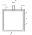
- FIG. 6 is a side view of the battery module 50 according to the second embodiment, in which a part of the exterior is transparent.
- the battery module 50 includes a plurality of battery cells 60 (60A, 60B, 60C, 60D) and an exterior pack 26.
- the battery module 50 only one valve device 200 is provided for the plurality of battery cells 60.
- the number of valve function portions is reduced as compared with the case where the valve device is provided in each of the plurality of battery cells 60, so that the inside of the battery cell 60 is prevented from a minute gap in the valve device. It is possible to reduce the possibility that water vapor will penetrate into. In other words, the amount of water that permeates one battery cell 60 can be reduced. Further, according to the valve device 200, the number of valve devices is reduced as compared with the case where one valve device is provided for each battery cell 60, so that the cost of the valve device in the battery module 50 can be suppressed.
- valve device body 210 (described later)
- the tip portion of the valve device 200 is located outside the exterior pack 26. That is, even if the valve device 200 operates in the battery module 50, the gas released from the valve device 200 is released at a position away from the exterior pack 26. Therefore, according to the valve device 200, since the gas is released to the outside of the exterior pack 26, it is possible to prevent the situation where the gas fills the exterior pack 26 and deteriorates the outer layer of the container of each battery cell 60. ..
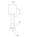
- the valve device 200 will be described in detail.
- FIG. 7 is a top view of the valve device 200.
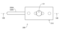
- FIG. 8 is a sectional view taken along line VIII-VIII of FIG. 7.
- the valve device 200 includes a valve device body 210, gas passage portions 220A, 220B, 220C and 220D, and attachment portions 230A, 230B, 230C and 230D.
- the valve device main body 210, the gas passage portions 220A, 220B, 220C, 220D, and the attachment portions 230A, 230B, 230C, 230D may be integrally formed or may be separately formed. For example, if each of them is configured separately, it is possible to select different materials as the material of each part.
- the valve device body 210 is made of, for example, metal or resin.
- the lowering structure (valve seat 112, ball 114, spring 116, membrane 118, and vent O1) is included.
- the structure is similar to that of the first embodiment.
- a plurality of (4) ventilation passages are branched in the lower portion of the structure.
- a gas passage portion 220 is continuously provided in each ventilation passage, and a mounting portion 230 is continuously provided in each gas passage portion 220.
- the helium leak amount of valve device main body 210 (valve device 200) is the same as the helium leak amount of valve device 100 according to the first embodiment.
- Each mounting part 230 is similar to the mounting part 130 in the first embodiment. Further, each gas passage portion 220 is the same as the gas passage portion 120 in the first embodiment except that the shape is different. The shape of each gas passage portion 220 is appropriately set according to the position of the attachment-destination battery cell 60 in the battery module 50.
- the gas guided inside the attachment portion 230 and the gas passage portion 220 vents the ball 114. Press to the O1 side.
- the gas in the battery cell 60 passes through the gap formed between the ball 114 and the valve seat 112, permeates the membrane 118, and passes through the ventilation port O1 to the battery cell 60. It is discharged to the outside of the (battery module 50).
- valve device 200 is attached to battery module 50 configured by stacking a plurality of housings (battery cells 60) each housing a battery element.
- valve device 200 only one valve device body 210 is provided for a plurality of battery cells 60. Therefore, according to the valve device 200, as compared with the case where the valve device is provided in each of the plurality of battery cells 60, water vapor is introduced into the battery cell 60 (inside the housing) through a minute gap in the valve device body 210. The possibility of infiltration can be reduced.
- valve device 200 only one valve device body 210 is provided for the plurality of gas passage portions 220. Therefore, according to the valve device 200, the number of valve device bodies is reduced as compared to the case where one valve device body is provided in each gas passage portion 220, and thus the cost of the valve device in the battery module 50 is suppressed. can do.
- the gas passage portions 120 and 220 are hollow.
- the insides of the gas passage portions 120 and 220 do not necessarily have to be hollow.
- a desiccant such as silica may be held inside the gas passage portions 120 and 220.
- the desiccant is held on the inner wall surfaces of the gas passage portions 120 and 220. In this case, when steam invades from the secondary side of the valve devices 100 and 200 to the primary side, the influence of the steam can be reduced.
- gas passage portions 120 and 220 in the first and second embodiments may be configured by, for example, bendable and flexible flexible tubes. This allows the gas discharge location to be adjusted more freely.
- gas passage portion 120 in the first embodiment described above does not necessarily have to be linear, and may be L-shaped, for example.
Landscapes
- Chemical & Material Sciences (AREA)
- Chemical Kinetics & Catalysis (AREA)
- Electrochemistry (AREA)
- General Chemical & Material Sciences (AREA)
- Gas Exhaust Devices For Batteries (AREA)
- Battery Mounting, Suspending (AREA)
- Sealing Battery Cases Or Jackets (AREA)
- Secondary Cells (AREA)
- Electric Double-Layer Capacitors Or The Like (AREA)
Priority Applications (7)
| Application Number | Priority Date | Filing Date | Title |
|---|---|---|---|
| KR1020217007978A KR102874995B1 (ko) | 2018-12-26 | 2019-12-26 | 밸브장치 및 조전지 |
| JP2020563398A JP7371640B2 (ja) | 2018-12-26 | 2019-12-26 | 弁装置及び組電池 |
| CN201980081318.8A CN113228395B (zh) | 2018-12-26 | 2019-12-26 | 阀装置和电池组 |
| KR1020257007022A KR20250035616A (ko) | 2018-12-26 | 2019-12-26 | 밸브장치 및 조전지 |
| KR1020257007021A KR20250035043A (ko) | 2018-12-26 | 2019-12-26 | 밸브장치 |
| US17/417,949 US12609408B2 (en) | 2018-12-26 | 2019-12-26 | Valve device and assembled battery |
| EP19904227.6A EP3905376A4 (en) | 2018-12-26 | 2019-12-26 | VALVE DEVICE AND COMPOSITE BATTERY |
Applications Claiming Priority (2)
| Application Number | Priority Date | Filing Date | Title |
|---|---|---|---|
| JP2018242470 | 2018-12-26 | ||
| JP2018-242470 | 2018-12-26 |
Publications (1)
| Publication Number | Publication Date |
|---|---|
| WO2020138254A1 true WO2020138254A1 (ja) | 2020-07-02 |
Family
ID=71128758
Family Applications (1)
| Application Number | Title | Priority Date | Filing Date |
|---|---|---|---|
| PCT/JP2019/051047 Ceased WO2020138254A1 (ja) | 2018-12-26 | 2019-12-26 | 弁装置及び組電池 |
Country Status (6)
| Country | Link |
|---|---|
| US (1) | US12609408B2 (https=) |
| EP (1) | EP3905376A4 (https=) |
| JP (1) | JP7371640B2 (https=) |
| KR (3) | KR20250035043A (https=) |
| CN (1) | CN113228395B (https=) |
| WO (1) | WO2020138254A1 (https=) |
Cited By (2)
| Publication number | Priority date | Publication date | Assignee | Title |
|---|---|---|---|---|
| JP2022099756A (ja) * | 2020-12-23 | 2022-07-05 | プライムプラネットエナジー&ソリューションズ株式会社 | 組電池 |
| US20240047816A1 (en) * | 2020-12-22 | 2024-02-08 | Bodo Konzelmann Kg | Emergency degassing device |
Families Citing this family (2)
| Publication number | Priority date | Publication date | Assignee | Title |
|---|---|---|---|---|
| KR102892123B1 (ko) * | 2019-04-26 | 2025-11-26 | 다이니폰 인사츠 가부시키가이샤 | 축전 디바이스용 밸브 구조체 |
| JP7584853B2 (ja) | 2021-08-13 | 2024-11-18 | エルジー・ケム・リミテッド | 高分子複合体およびそれを含む成形品 |
Citations (7)
| Publication number | Priority date | Publication date | Assignee | Title |
|---|---|---|---|---|
| JP2004006213A (ja) | 2002-03-22 | 2004-01-08 | Matsushita Electric Ind Co Ltd | 電池パック |
| JP2006202560A (ja) * | 2005-01-19 | 2006-08-03 | Toyota Motor Corp | 密閉型電池の製造方法、及び、気密検査装置 |
| JP2011175844A (ja) * | 2010-02-24 | 2011-09-08 | Mitsubishi Heavy Ind Ltd | 電池パック |
| JP2014075251A (ja) * | 2012-10-04 | 2014-04-24 | Toyota Motor Corp | 電池モジュール |
| JP2015018706A (ja) * | 2013-07-11 | 2015-01-29 | 株式会社豊田自動織機 | 蓄電装置モジュール |
| JP2015046354A (ja) * | 2013-08-29 | 2015-03-12 | 古河電気工業株式会社 | 電池モジュール用カバー、電池モジュール |
| JP2017091950A (ja) * | 2015-11-16 | 2017-05-25 | トヨタ自動車株式会社 | 車載用バッテリ装置 |
Family Cites Families (17)
| Publication number | Priority date | Publication date | Assignee | Title |
|---|---|---|---|---|
| US2232279A (en) * | 1938-03-16 | 1941-02-18 | Nat Battery Co | Vent plug for aircraft batteries |
| US5876872A (en) | 1996-11-08 | 1999-03-02 | Feezor; Michael D. | Underwater rechargeable battery and method of manufacture |
| JP2003045395A (ja) * | 2001-07-30 | 2003-02-14 | Sanyo Electric Co Ltd | 密閉型蓄電池 |
| JP4810797B2 (ja) * | 2004-05-06 | 2011-11-09 | トヨタ自動車株式会社 | 電池モジュールと組電池 |
| JP4249698B2 (ja) | 2004-11-25 | 2009-04-02 | 日本電気株式会社 | フィルム外装電気デバイスおよびフィルム外装電気デバイス集合体 |
| WO2006098242A1 (ja) | 2005-03-17 | 2006-09-21 | Nec Corporation | フィルム外装電気デバイスおよびその製造方法 |
| JP2008117756A (ja) * | 2006-10-13 | 2008-05-22 | Matsushita Electric Ind Co Ltd | 電池パック、及び電池搭載機器 |
| JP5099415B2 (ja) * | 2007-04-13 | 2012-12-19 | 株式会社Gsユアサ | 制御弁式鉛蓄電池 |
| JP2009043670A (ja) * | 2007-08-10 | 2009-02-26 | Kojima Press Co Ltd | 電池における排ガスチューブ |
| JP5507173B2 (ja) * | 2009-09-25 | 2014-05-28 | パナソニック株式会社 | 電池モジュールとそれを用いた電池パック |
| CN103430348A (zh) * | 2011-03-16 | 2013-12-04 | 丰田自动车株式会社 | 蓄电装置 |
| EP2709191A4 (en) | 2012-03-28 | 2015-08-19 | Optnics Prec Co Ltd | SAFETY VALVE AND ELECTROCHEMICAL ELEMENT |
| US9401501B2 (en) * | 2012-05-18 | 2016-07-26 | 24M Technologies, Inc. | Electrochemical cells and methods of manufacturing the same |
| KR101618296B1 (ko) * | 2014-04-15 | 2016-05-18 | 삼화전기 주식회사 | 에너지 저장장치용 안전변 |
| KR102275273B1 (ko) * | 2014-07-29 | 2021-07-09 | 에스케이이노베이션 주식회사 | 파우치형 리튬 이차전지의 벤팅 시스템 |
| WO2016039248A1 (ja) * | 2014-09-09 | 2016-03-17 | 大日本印刷株式会社 | 薬液収納用包装袋および薬液収納用容器 |
| JP6260590B2 (ja) | 2015-07-14 | 2018-01-17 | トヨタ自動車株式会社 | 非水系二次電池 |
-
2019
- 2019-12-26 CN CN201980081318.8A patent/CN113228395B/zh active Active
- 2019-12-26 JP JP2020563398A patent/JP7371640B2/ja active Active
- 2019-12-26 KR KR1020257007021A patent/KR20250035043A/ko active Pending
- 2019-12-26 WO PCT/JP2019/051047 patent/WO2020138254A1/ja not_active Ceased
- 2019-12-26 KR KR1020257007022A patent/KR20250035616A/ko active Pending
- 2019-12-26 EP EP19904227.6A patent/EP3905376A4/en active Pending
- 2019-12-26 US US17/417,949 patent/US12609408B2/en active Active
- 2019-12-26 KR KR1020217007978A patent/KR102874995B1/ko active Active
Patent Citations (7)
| Publication number | Priority date | Publication date | Assignee | Title |
|---|---|---|---|---|
| JP2004006213A (ja) | 2002-03-22 | 2004-01-08 | Matsushita Electric Ind Co Ltd | 電池パック |
| JP2006202560A (ja) * | 2005-01-19 | 2006-08-03 | Toyota Motor Corp | 密閉型電池の製造方法、及び、気密検査装置 |
| JP2011175844A (ja) * | 2010-02-24 | 2011-09-08 | Mitsubishi Heavy Ind Ltd | 電池パック |
| JP2014075251A (ja) * | 2012-10-04 | 2014-04-24 | Toyota Motor Corp | 電池モジュール |
| JP2015018706A (ja) * | 2013-07-11 | 2015-01-29 | 株式会社豊田自動織機 | 蓄電装置モジュール |
| JP2015046354A (ja) * | 2013-08-29 | 2015-03-12 | 古河電気工業株式会社 | 電池モジュール用カバー、電池モジュール |
| JP2017091950A (ja) * | 2015-11-16 | 2017-05-25 | トヨタ自動車株式会社 | 車載用バッテリ装置 |
Cited By (3)
| Publication number | Priority date | Publication date | Assignee | Title |
|---|---|---|---|---|
| US20240047816A1 (en) * | 2020-12-22 | 2024-02-08 | Bodo Konzelmann Kg | Emergency degassing device |
| JP2022099756A (ja) * | 2020-12-23 | 2022-07-05 | プライムプラネットエナジー&ソリューションズ株式会社 | 組電池 |
| JP7337042B2 (ja) | 2020-12-23 | 2023-09-01 | プライムプラネットエナジー&ソリューションズ株式会社 | 組電池 |
Also Published As
| Publication number | Publication date |
|---|---|
| KR102874995B1 (ko) | 2025-10-21 |
| KR20210107616A (ko) | 2021-09-01 |
| KR20250035043A (ko) | 2025-03-11 |
| JP7371640B2 (ja) | 2023-10-31 |
| EP3905376A1 (en) | 2021-11-03 |
| US20220077538A1 (en) | 2022-03-10 |
| CN113228395B (zh) | 2023-07-25 |
| US12609408B2 (en) | 2026-04-21 |
| KR20250035616A (ko) | 2025-03-12 |
| JPWO2020138254A1 (ja) | 2021-11-18 |
| EP3905376A4 (en) | 2023-03-29 |
| CN113228395A (zh) | 2021-08-06 |
Similar Documents
| Publication | Publication Date | Title |
|---|---|---|
| WO2020138254A1 (ja) | 弁装置及び組電池 | |
| US10446818B2 (en) | Power source device | |
| US12424700B2 (en) | Heat sealing apparatus for a battery | |
| CN112272889B (zh) | 电池 | |
| JP4959657B2 (ja) | 封口装置及び密閉容器 | |
| JP2020053381A (ja) | 蓄電デバイス用弁装置及び蓄電デバイス | |
| US12308466B2 (en) | Valve device for power storage device and power storage device | |
| CN112236897A (zh) | 电池 | |
| US11575177B2 (en) | Battery packaging material, having a valve device | |
| JP6624317B1 (ja) | 弁装置及び組電池 | |
| JP7259713B2 (ja) | 弁装置及び組電池 | |
| KR20230088685A (ko) | 축전 디바이스용 밸브 구조체, 및 축전 디바이스 | |
| WO2020184689A1 (ja) | 包装容器及びこれを備える蓄電デバイス | |
| JP7579050B2 (ja) | 蓄電デバイス用弁装置及び蓄電デバイス | |
| JP2024045178A (ja) | 蓄電デバイス用弁装置及び蓄電デバイス | |
| JP2022066148A (ja) | 蓄電デバイス用弁構造体、および、蓄電デバイス | |
| JP2020071945A (ja) | 蓄電装置 | |
| JP2012199297A (ja) | 蓄電デバイス |
Legal Events
| Date | Code | Title | Description |
|---|---|---|---|
| 121 | Ep: the epo has been informed by wipo that ep was designated in this application |
Ref document number: 19904227 Country of ref document: EP Kind code of ref document: A1 |
|
| ENP | Entry into the national phase |
Ref document number: 20217007978 Country of ref document: KR Kind code of ref document: A |
|
| ENP | Entry into the national phase |
Ref document number: 2020563398 Country of ref document: JP Kind code of ref document: A |
|
| NENP | Non-entry into the national phase |
Ref country code: DE |
|
| ENP | Entry into the national phase |
Ref document number: 2019904227 Country of ref document: EP Effective date: 20210726 |
|
| WWP | Wipo information: published in national office |
Ref document number: 1020257007022 Country of ref document: KR |