WO2020137814A1 - Dispositif de codage d'image, procédé de codage d'image, programme de codage d'image, dispositif de décodage d'image, procédé de décodage d'image et programme de décodage d'image - Google Patents
Dispositif de codage d'image, procédé de codage d'image, programme de codage d'image, dispositif de décodage d'image, procédé de décodage d'image et programme de décodage d'image Download PDFInfo
- Publication number
- WO2020137814A1 WO2020137814A1 PCT/JP2019/049864 JP2019049864W WO2020137814A1 WO 2020137814 A1 WO2020137814 A1 WO 2020137814A1 JP 2019049864 W JP2019049864 W JP 2019049864W WO 2020137814 A1 WO2020137814 A1 WO 2020137814A1
- Authority
- WO
- WIPO (PCT)
- Prior art keywords
- motion vector
- vector predictor
- history
- candidate list
- merge
- Prior art date
Links
- 238000000034 method Methods 0.000 title claims description 157
- 230000033001 locomotion Effects 0.000 claims abstract description 788
- 239000013598 vector Substances 0.000 claims abstract description 707
- 238000005516 engineering process Methods 0.000 abstract description 2
- 238000012545 processing Methods 0.000 description 137
- 238000009795 derivation Methods 0.000 description 104
- 230000008569 process Effects 0.000 description 76
- 230000009466 transformation Effects 0.000 description 31
- PXFBZOLANLWPMH-UHFFFAOYSA-N 16-Epiaffinine Natural products C1C(C2=CC=CC=C2N2)=C2C(=O)CC2C(=CC)CN(C)C1C2CO PXFBZOLANLWPMH-UHFFFAOYSA-N 0.000 description 29
- 230000002123 temporal effect Effects 0.000 description 19
- 238000013139 quantization Methods 0.000 description 18
- 238000010586 diagram Methods 0.000 description 17
- 238000007792 addition Methods 0.000 description 15
- 230000005540 biological transmission Effects 0.000 description 5
- 238000012790 confirmation Methods 0.000 description 5
- 230000006870 function Effects 0.000 description 5
- 230000011218 segmentation Effects 0.000 description 5
- 238000012217 deletion Methods 0.000 description 4
- 230000037430 deletion Effects 0.000 description 4
- 238000012986 modification Methods 0.000 description 4
- 230000004048 modification Effects 0.000 description 4
- 230000009469 supplementation Effects 0.000 description 4
- 238000004364 calculation method Methods 0.000 description 3
- 230000003287 optical effect Effects 0.000 description 3
- 230000001502 supplementing effect Effects 0.000 description 3
- 238000006243 chemical reaction Methods 0.000 description 2
- 238000004891 communication Methods 0.000 description 2
- 239000000470 constituent Substances 0.000 description 2
- 238000001514 detection method Methods 0.000 description 2
- 238000001914 filtration Methods 0.000 description 2
- 230000006872 improvement Effects 0.000 description 2
- 238000005457 optimization Methods 0.000 description 2
- 238000012935 Averaging Methods 0.000 description 1
- 239000000872 buffer Substances 0.000 description 1
- 230000003139 buffering effect Effects 0.000 description 1
- 238000003384 imaging method Methods 0.000 description 1
- 238000011423 initialization method Methods 0.000 description 1
- 238000012804 iterative process Methods 0.000 description 1
- 230000009467 reduction Effects 0.000 description 1
- 230000001131 transforming effect Effects 0.000 description 1
Images


Classifications
-
- H—ELECTRICITY
- H04—ELECTRIC COMMUNICATION TECHNIQUE
- H04N—PICTORIAL COMMUNICATION, e.g. TELEVISION
- H04N19/00—Methods or arrangements for coding, decoding, compressing or decompressing digital video signals
- H04N19/50—Methods or arrangements for coding, decoding, compressing or decompressing digital video signals using predictive coding
- H04N19/503—Methods or arrangements for coding, decoding, compressing or decompressing digital video signals using predictive coding involving temporal prediction
- H04N19/51—Motion estimation or motion compensation
- H04N19/513—Processing of motion vectors
-
- H—ELECTRICITY
- H04—ELECTRIC COMMUNICATION TECHNIQUE
- H04N—PICTORIAL COMMUNICATION, e.g. TELEVISION
- H04N19/00—Methods or arrangements for coding, decoding, compressing or decompressing digital video signals
- H04N19/10—Methods or arrangements for coding, decoding, compressing or decompressing digital video signals using adaptive coding
- H04N19/169—Methods or arrangements for coding, decoding, compressing or decompressing digital video signals using adaptive coding characterised by the coding unit, i.e. the structural portion or semantic portion of the video signal being the object or the subject of the adaptive coding
- H04N19/17—Methods or arrangements for coding, decoding, compressing or decompressing digital video signals using adaptive coding characterised by the coding unit, i.e. the structural portion or semantic portion of the video signal being the object or the subject of the adaptive coding the unit being an image region, e.g. an object
- H04N19/176—Methods or arrangements for coding, decoding, compressing or decompressing digital video signals using adaptive coding characterised by the coding unit, i.e. the structural portion or semantic portion of the video signal being the object or the subject of the adaptive coding the unit being an image region, e.g. an object the region being a block, e.g. a macroblock
-
- H—ELECTRICITY
- H04—ELECTRIC COMMUNICATION TECHNIQUE
- H04N—PICTORIAL COMMUNICATION, e.g. TELEVISION
- H04N19/00—Methods or arrangements for coding, decoding, compressing or decompressing digital video signals
- H04N19/10—Methods or arrangements for coding, decoding, compressing or decompressing digital video signals using adaptive coding
- H04N19/102—Methods or arrangements for coding, decoding, compressing or decompressing digital video signals using adaptive coding characterised by the element, parameter or selection affected or controlled by the adaptive coding
- H04N19/103—Selection of coding mode or of prediction mode
- H04N19/105—Selection of the reference unit for prediction within a chosen coding or prediction mode, e.g. adaptive choice of position and number of pixels used for prediction
-
- H—ELECTRICITY
- H04—ELECTRIC COMMUNICATION TECHNIQUE
- H04N—PICTORIAL COMMUNICATION, e.g. TELEVISION
- H04N19/00—Methods or arrangements for coding, decoding, compressing or decompressing digital video signals
- H04N19/10—Methods or arrangements for coding, decoding, compressing or decompressing digital video signals using adaptive coding
- H04N19/134—Methods or arrangements for coding, decoding, compressing or decompressing digital video signals using adaptive coding characterised by the element, parameter or criterion affecting or controlling the adaptive coding
- H04N19/136—Incoming video signal characteristics or properties
- H04N19/137—Motion inside a coding unit, e.g. average field, frame or block difference
-
- H—ELECTRICITY
- H04—ELECTRIC COMMUNICATION TECHNIQUE
- H04N—PICTORIAL COMMUNICATION, e.g. TELEVISION
- H04N19/00—Methods or arrangements for coding, decoding, compressing or decompressing digital video signals
- H04N19/44—Decoders specially adapted therefor, e.g. video decoders which are asymmetric with respect to the encoder
-
- H—ELECTRICITY
- H04—ELECTRIC COMMUNICATION TECHNIQUE
- H04N—PICTORIAL COMMUNICATION, e.g. TELEVISION
- H04N19/00—Methods or arrangements for coding, decoding, compressing or decompressing digital video signals
- H04N19/50—Methods or arrangements for coding, decoding, compressing or decompressing digital video signals using predictive coding
- H04N19/503—Methods or arrangements for coding, decoding, compressing or decompressing digital video signals using predictive coding involving temporal prediction
- H04N19/51—Motion estimation or motion compensation
- H04N19/513—Processing of motion vectors
- H04N19/517—Processing of motion vectors by encoding
- H04N19/52—Processing of motion vectors by encoding by predictive encoding
-
- H—ELECTRICITY
- H04—ELECTRIC COMMUNICATION TECHNIQUE
- H04N—PICTORIAL COMMUNICATION, e.g. TELEVISION
- H04N19/00—Methods or arrangements for coding, decoding, compressing or decompressing digital video signals
- H04N19/70—Methods or arrangements for coding, decoding, compressing or decompressing digital video signals characterised by syntax aspects related to video coding, e.g. related to compression standards
Definitions
- the present invention relates to an image encoding and decoding technique that divides an image into blocks and performs prediction.
- the image to be processed is divided into blocks that are a set of a specified number of pixels, and processing is performed in block units.
- processing is performed in block units.
- Patent Document 1 describes a technique of applying an affine transformation at the time of inter prediction. In a moving image, it is not uncommon for an object to undergo deformation such as enlargement/reduction or rotation, and application of the technique of Patent Document 1 enables efficient encoding.
- Patent Document 1 since the technique of Patent Document 1 involves image conversion, there is a problem that the processing load is large. In view of the above problems, the present invention provides a low-load and efficient encoding technique.
- the image coding apparatus is a coding information storage unit that fills all history candidates in a history motion vector predictor candidate list with at least a predetermined motion vector and a reference index.
- a merge candidate list generation unit that generates a merge candidate list including at least a motion vector and a reference index of a block adjacent to an encoding target block as merge candidates; and merge history candidates included in the history motion vector predictor candidate list.
- a history merge candidate addition unit that adds a merge candidate to the candidate list and outputs a second merge candidate list, and a merge candidate selection unit that selects a merge candidate from the second merge candidate list as a selected merge candidate.
- the encoding information storage unit adds the selected merge candidate to the history motion vector predictor candidate list as a history candidate and outputs the history motion vector predictor candidate list.
- the image coding method includes a coding information storing step of filling all history candidates in the history motion vector predictor candidate list with at least a predetermined motion vector and a reference index, and adjacent to a coding target block.
- the selected merge candidate is added as a history candidate to the history motion vector predictor candidate list, and the history motion vector predictor candidate list is output.
- An image encoding program includes an encoding information storing step of filling all history candidates in a history motion vector predictor candidate list with at least a predetermined motion vector and a reference index, and adjacent to an encoding target block.
- a merge candidate list generation step of generating a merge candidate list including at least a motion vector and a reference index of a block as a merge candidate, and adding a history candidate included in the history prediction motion vector candidate list to the merge candidate list as a merge candidate.
- the step adds the selected merge candidate as a history candidate to the history motion vector predictor candidate list and outputs the history motion vector predictor candidate list.
- An image decoding apparatus is an encoding information storage unit that fills all history candidates in a history motion vector predictor candidate list with at least a predetermined motion vector and a reference index, and a block adjacent to a decoding target block.
- a merge candidate list generation unit that generates a merge candidate list including at least a motion vector and a reference index as a merge candidate, and a history candidate included in the history motion vector predictor candidate list is added as a merge candidate to the merge candidate list.
- a history candidate merge candidate adding unit that outputs a second merge candidate list; and a merge candidate selecting unit that selects a merge candidate from the second merge candidate list as a selected merge candidate. The selected merge candidate is added as a history candidate to the history motion vector predictor candidate list and the history motion vector predictor candidate list is output.
- An image decoding method is the encoding information storing step of filling all history candidates in the history motion vector predictor candidate list with at least a predetermined motion vector and a reference index, and a block adjacent to the decoding target block.
- An image decoding program comprising: an encoding information storing step of filling all history candidates of the history motion vector predictor candidate list with at least a predetermined motion vector and a reference index; A merge candidate list generation step of generating a merge candidate list including at least a motion vector and a reference index of a block as a merge candidate, and adding a history candidate included in the history prediction motion vector candidate list to the merge candidate list as a merge candidate.
- a history merge candidate addition step of outputting a second merge candidate list and a merge candidate selection step of selecting a merge candidate as a selected merge candidate from the second merge candidate list, and storing the encoded information.
- the step adds the selected merge candidate as a history candidate to the history motion vector predictor candidate list and outputs the history motion vector predictor candidate list.
- FIG. 3 is a block diagram of an image encoding device according to an embodiment of the present invention. It is a block diagram of an image decoding device according to an embodiment of the present invention.
- 7 is a flowchart illustrating an operation of dividing a tree block. It is a figure which shows a mode that the input image is divided into tree blocks. It is a figure explaining z-scan. It is a figure which shows the division
- FIG. 6 is a flowchart for explaining an operation of dividing a block into four. 6 is a flowchart for explaining an operation of dividing a block into two or three. It is a syntax for expressing the shape of block division. It is a figure for explaining intra prediction. It is a figure for explaining intra prediction. It is a figure for demonstrating the reference block of inter prediction. It is a syntax for expressing a coding block prediction mode. It is a figure which shows the correspondence of the syntax element and mode regarding inter prediction. It is a figure for demonstrating the affine transformation motion compensation of two control points. It is a figure for demonstrating the affine transformation motion compensation of three control points.
- FIG. 3 is a block diagram of a detailed configuration of an inter prediction unit 102 in FIG. 1.
- FIG. FIG. 17 is a block diagram of a detailed configuration of a normal motion vector predictor mode deriving unit 301 in FIG. 16.
- FIG. 17 is a block diagram of a detailed configuration of a normal merge mode derivation unit 302 in FIG. 16.
- 17 is a flowchart for explaining a normal motion vector predictor mode derivation process of the normal motion vector predictor mode deriving unit 301 in FIG. 16. It is a flow chart showing a processing procedure of normal prediction motion vector mode derivation processing. It is a flow chart explaining the processing procedure of normal merge mode derivation processing.
- 3 is a block diagram of a detailed configuration of an inter prediction unit 203 in FIG. 2.
- FIG. 23 is a block diagram of a detailed configuration of a normal motion vector predictor mode deriving unit 401 in FIG. 22.
- FIG. FIG. 23 is a block diagram of a detailed configuration of a normal merge mode derivation unit 402 in FIG. 22.
- 23 is a flowchart for explaining the normal motion vector predictor mode derivation process of the normal motion vector predictor mode deriving unit 401 in FIG. 22. It is a figure explaining a history motion vector predictor candidate list initialization and update processing procedure.
- 11 is a flowchart of the same element confirmation processing procedure in the history motion vector predictor candidate list initialization/update processing procedure.
- 11 is a flowchart of an element shift processing procedure in a history motion vector predictor candidate list initialization/update processing procedure.
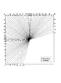
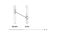
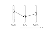
- Fig. 3 is a diagram for describing a prediction direction of motion-compensated prediction in the case of bi-prediction and a reference picture for L0 prediction and a reference picture for L1 prediction are at a time before a picture to be processed.
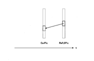
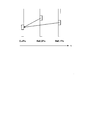
- Fig. 3 is a diagram for describing a prediction direction of motion compensation prediction in the case of bi-prediction and a reference picture for L0 prediction and a reference picture for L1 prediction are at a time later than a picture to be processed.
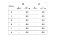
- 11 is a table showing another example of the history motion vector predictor candidates added by the initialization of the history motion vector predictor candidate list.
- 11 is a table showing another example of the history motion vector predictor candidates added by the initialization of the history motion vector predictor candidate list.
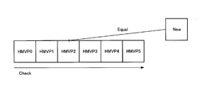
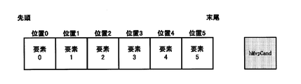
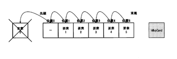
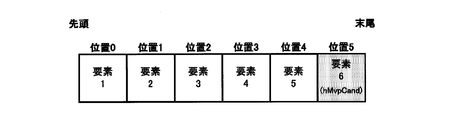
- 11 is a table showing another example of the history motion vector predictor candidates added by the initialization of the history motion vector predictor candidate list. It is a figure for demonstrating the structure of a history prediction motion vector candidate list. It is a figure for explaining a mode that a head element is deleted at the time of addition to a history prediction motion vector candidate list.
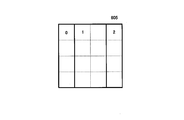
- the encoding/decoding processing target image is equally divided into a predetermined size.
- This unit is defined as a tree block.
- the size of the tree block is 128 ⁇ 128 pixels in FIG. 4, the size of the tree block is not limited to this, and any size may be set.
- the tree blocks to be processed (corresponding to the encoding target in the encoding process and the decoding target in the decoding process) are switched in raster scan order, that is, from left to right and from top to bottom. The inside of each tree block can be further recursively divided.
- a block to be encoded/decoded after the tree block is recursively divided is defined as an encoded block.
- the tree block and the coding block are collectively defined as a block. Efficient encoding is possible by performing appropriate block division.
- the size of the tree block can be a fixed value pre-arranged by the encoding device and the decoding device, or the size of the tree block determined by the encoding device can be transmitted to the decoding device.
- the maximum size of the tree block is 128 ⁇ 128 pixels
- the minimum size of the tree block is 16 ⁇ 16 pixels.
- the maximum size of the coded block is 64x64 pixels
- the minimum size of the coded block is 4x4 pixels.
- Intra prediction that performs prediction from the processed image signal of the processing target image
- inter prediction MODE_INTER
- the processed image is used for an image obtained by decoding a signal that has been encoded in the encoding process, an image signal, a tree block, a block, an encoded block, etc., and an image, an image signal, for which the decoding has been completed in the decoding process. Used for tree blocks, blocks, coding blocks, etc.
- the prediction mode (PredMode) has intra prediction (MODE_INTRA) or inter prediction (MODE_INTER) as a value.
- L0 prediction is available for P slices.
- Pred_L0 L0 prediction
- Pred_L1 L1 prediction
- Pred_BI bi-prediction
- L0 prediction is inter prediction that refers to a reference picture managed by L0
- L1 prediction is inter prediction that refers to a reference picture managed by L1.
- Bi-prediction is inter prediction in which both L0 prediction and L1 prediction are performed and one reference picture managed by each of L0 and L1 is referred to.
- Information that specifies L0 prediction, L1 prediction, and bi-prediction is defined as an inter prediction mode. In the subsequent processing, it is premised that the processing is performed for each of L0 and L1 for the constants and variables with the subscript LX attached to the output.
- the motion vector predictor mode is a mode in which an index for specifying a motion vector predictor, a differential motion vector, an inter prediction mode, and a reference index are transmitted to determine inter prediction information of a block to be processed.
- the motion vector predictor includes a motion vector predictor candidate derived from a processed block adjacent to the process target block, or a block belonging to the processed image and located at the same position as the process target block or in the vicinity (neighboring) of the process target block, and the motion vector predictor. It is derived from the index for identifying the vector.
- the merge mode is a processed block that is adjacent to the processing target block without transmitting the differential motion vector or the reference index, or a block that belongs to the processed image and is located at the same position as the processing target block or in the vicinity thereof (nearby). This is a mode for deriving the inter prediction information of the processing target block from the inter prediction information of.
- the processed block adjacent to the block to be processed and the inter prediction information of the processed block as spatial merge candidates.
- a block that belongs to the processed image and is located at the same position as or near (the vicinity of) the block to be processed and the inter prediction information derived from the inter prediction information of the block are defined as temporal merge candidates.
- Each merge candidate is registered in the merge candidate list, and the merge index is used to identify the merge candidate used for prediction of the block to be processed.
- FIG. 11 is a diagram illustrating reference blocks referred to in order to derive inter prediction information in the motion vector predictor mode and the merge mode.
- A0, A1, A2, B0, B1, B2, B3 are processed blocks adjacent to the processing target block.
- T0 is a block belonging to the processed image, which is located at the same position as the processing target block in the processing target image or in the vicinity (neighborhood) thereof.
- A1 and A2 are blocks located on the left side of the processing target coding block and adjacent to the processing target coding block.
- B1 and B3 are blocks located above the coding block to be processed and adjacent to the coding block to be processed.
- A0, B0, and B2 are blocks located at the lower left, upper right, and upper left of the process target coding block, respectively.
- Affine transform motion compensation is to perform motion compensation by dividing a coded block into sub-blocks of a predetermined unit and individually determining a motion vector for each of the divided sub-blocks.
- the motion vector of each sub-block is derived from inter prediction information of a processed block adjacent to the processing target block, or a block belonging to the processed image and located at the same position as the processing target block or in the vicinity (neighborhood) thereof 1 It derives based on one or more control points.
- the size of the sub block is 4 ⁇ 4 pixels, but the size of the sub block is not limited to this, and the motion vector may be derived in pixel units.
- FIG. 14 shows an example of affine transformation motion compensation when there are two control points.
- the two control points have two parameters, a horizontal component and a vertical component. Therefore, the affine transformation when there are two control points is called a four-parameter affine transformation.
- CP1 and CP2 in FIG. 14 are control points.
- FIG. 15 shows an example of affine transformation motion compensation when there are three control points. In this case, the three control points have two parameters, a horizontal component and a vertical component. Therefore, the affine transformation when there are three control points is called a 6-parameter affine transformation.
- CP1, CP2, and CP3 in FIG. 15 are control points.
- Affine transform motion compensation can be used in both the motion vector predictor mode and the merge mode.
- the mode in which the affine transform motion compensation is applied in the motion vector predictor mode is defined as the sub-block motion vector predictor mode
- the mode in which the affine transform motion compensation is applied in the merge mode is defined as the sub-block merge mode.
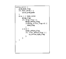
- the merge_flag in FIG. 12 is a flag indicating whether the process target coding block is in the merge mode or the motion vector predictor mode.
- merge_affine_flag is a flag indicating whether or not the sub-block merge mode is applied to the processing target coding block in the merge mode.
- inter_affine_flag is a flag indicating whether or not to apply the sub-block motion vector predictor mode in the processing target coding block of the motion vector predictor mode.
- cu_affine_type_flag is a flag for determining the number of control points in the sub-block motion vector predictor mode.
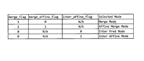
- FIG. 13 shows the value of each syntax element and the corresponding prediction method.
- the normal merge mode is a merge mode that is not a sub-block merge.
- the normal motion vector predictor mode is a motion vector predictor merge that is not the sub-block motion vector predictor mode.
- POC Picture Order Count
- POC Picture Order Count
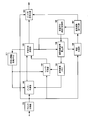
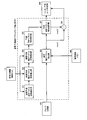
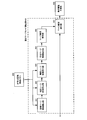
- FIG. 1 is a block diagram of an image encoding device 100 according to the first embodiment.
- the image coding apparatus 100 includes a block division unit 101, an inter prediction unit 102, an intra prediction unit 103, a decoded image memory 104, a prediction method determination unit 105, a residual generation unit 106, an orthogonal transformation/quantization unit 107.
- the block dividing unit 101 recursively divides the input image to generate a coded block.
- the block division unit 101 includes a four division unit that divides a block to be divided into a horizontal direction and a vertical direction, and a 2-3 division unit that divides a block to be divided into either a horizontal direction or a vertical direction. Including.
- the block division unit 101 sets the generated coding block as a processing target coding block, and supplies the image signal of the processing target coding block to the inter prediction unit 102, the intra prediction unit 103, and the residual generation unit 106.
- the block division unit 101 also supplies information indicating the determined recursive division structure to the bit string encoding unit 108. The detailed operation of the block division unit 101 will be described later.
- the inter prediction unit 102 performs inter prediction of the coding block to be processed.
- the inter prediction unit 102 derives a plurality of inter prediction information candidates from the inter prediction information stored in the encoded information storage memory 111 and the decoded image signal stored in the decoded image memory 104, An appropriate inter prediction mode is selected from the derived plurality of candidates, and the selected inter prediction mode and the predicted image signal corresponding to the selected inter prediction mode are supplied to the prediction method determination unit 105.
- the detailed configuration and operation of the inter prediction unit 102 will be described later.
- the intra prediction unit 103 performs intra prediction of the process target coding block.
- the intra prediction unit 103 refers to the decoded image signal stored in the decoded image memory 104 as a reference pixel, and performs intra prediction based on the coding information such as the intra prediction mode stored in the coding information storage memory 111. To generate a predicted image signal.
- the intra prediction unit 103 selects a suitable intra prediction mode from a plurality of intra prediction modes, and predicts a selected intra prediction mode and a prediction image signal corresponding to the selected intra prediction mode. It is supplied to the determining unit 105.
- FIGS. 10A and 10B An example of intra prediction is shown in FIGS. 10A and 10B.
- FIG. 10A shows the correspondence between the prediction direction of intra prediction and the intra prediction mode number.
- the intra prediction mode 50 generates an intra prediction image by copying the reference pixel in the vertical direction.
- the intra prediction mode 1 is a DC mode in which all the pixel values of the processing target block are the average value of the reference pixels.
- Intra prediction mode 0 is a Planar mode, and is a mode in which a two-dimensional intra prediction image is created from reference pixels in the vertical and horizontal directions.
- FIG. 10B is an example of generating an intra prediction image in the case of the intra prediction mode 40.
- the intra prediction unit 103 copies the value of the reference pixel in the direction indicated by the intra prediction mode for each pixel of the processing target block. When the reference pixel in the intra prediction mode is not an integer position, the intra prediction unit 103 determines the reference pixel value by interpolation from the reference pixel values at the surrounding integer positions.
- the decoded image memory 104 stores the decoded image generated by the decoded image signal superimposing unit 110.
- the decoded image memory 104 supplies the stored decoded image to the inter prediction unit 102 and the intra prediction unit 103.
- the prediction method determination unit 105 evaluates each of the intra prediction and the inter prediction by using the coding amount of the coding information and the residual, the distortion amount between the predicted image signal and the processing target image signal, and the like. , Determine the optimal prediction mode.
- the prediction method determination unit 105 supplies intra prediction information such as the intra prediction mode to the bit string coding unit 108 as coding information.
- the prediction method determination unit 105 uses the inter-prediction information such as the merge index and information (sub-block merge flag) indicating whether or not the sub-block merge mode is the bit string encoding unit 108 as the encoding information. Supply to.
- the prediction method determination unit 105 is information indicating whether the inter prediction mode, the motion vector predictor index, the reference indexes of L0 and L1, the differential motion vector, and the sub block motion vector predictor mode. Inter prediction information such as (sub-block motion vector predictor flag) is supplied to the bit string coding unit 108 as coding information. Furthermore, the prediction method determination unit 105 supplies the determined coding information to the coding information storage memory 111. The prediction method determination unit 105 supplies the residual error generation unit 106 and the predicted image signal to the decoded image signal superposition unit 110.
- the residual generation unit 106 generates a residual by subtracting the predicted image signal from the image signal to be processed, and supplies the residual to the orthogonal transformation/quantization unit 107.
- the orthogonal transformation/quantization unit 107 performs orthogonal transformation and quantization on the residual according to the quantization parameter to generate an orthogonal transformation/quantized residual, and the generated residual is the bit string encoding unit 108. And the inverse quantization/inverse orthogonal transformation unit 109.
- the bit string coding unit 108 codes coding information according to the prediction method determined by the prediction method determination unit 105 for each coding block, in addition to information on a sequence, picture, slice, and coding block unit. Specifically, the bit string coding unit 108 codes the prediction mode PredMode for each coding block.
- the bit string encoding unit 108 determines whether or not the mode is the merge mode, the sub-block merge flag, the merge index in the case of the merge mode, the inter prediction mode in the case of not the merge mode, Coding information (inter prediction information) such as a motion vector predictor index, information about a differential motion vector, and a sub-block motion vector predictor flag is coded according to a prescribed syntax (syntax rule of bit string) to generate a first bit string.
- the prediction mode is intra prediction (MODE_INTRA)
- the coding information intra prediction information
- intra prediction mode is coded according to the prescribed syntax (bit string syntax rule) to generate the first bit string.
- bit string encoding unit 108 entropy-encodes the orthogonally transformed and quantized residual according to a prescribed syntax to generate a second bit string.
- the bit string encoding unit 108 multiplexes the first bit string and the second bit string according to a prescribed syntax and outputs a bit stream.
- the inverse quantization/inverse orthogonal transformation unit 109 performs inverse quantization and inverse orthogonal transformation on the orthogonal transformation/quantized residual supplied from the orthogonal transformation/quantization unit 107 to calculate the residual, and the calculated residual. The difference is supplied to the decoded image signal superimposing unit 110.
- the decoded image signal superimposing unit 110 superimposes the prediction image signal according to the determination made by the prediction method determining unit 105 and the residuals that have been inversely quantized and inversely orthogonally transformed by the inverse quantization/inverse orthogonal transformation unit 109 to obtain a decoded image. It is generated and stored in the decoded image memory 104. Note that the decoded image signal superimposing unit 110 may store the decoded image in the decoded image memory 104 after performing a filtering process on the decoded image to reduce distortion such as block distortion due to encoding.
- the coding information storage memory 111 stores the coding information such as the prediction mode (inter prediction or intra prediction) determined by the prediction method determination unit 105.
- the coding information stored in the coding information storage memory 111 includes inter prediction information such as the determined motion vector, the reference index of the reference lists L0 and L1, the history prediction motion vector candidate list, and the like.
- the coding information stored in the coding information storage memory 111 includes, in addition to the above-described information, information indicating whether or not the merge index and the sub block merge mode (sub block merge flag). ) Inter prediction information is included.
- the coding information stored in the coding information storage memory 111 includes the inter prediction mode, the motion vector predictor index, the difference motion vector, and the sub block prediction in addition to the above-mentioned information.
- Inter prediction information such as information (sub-block prediction motion vector flag) indicating whether or not the motion vector mode is included.
- the coding information stored in the coding information storage memory 111 includes intra prediction information such as the determined intra prediction mode.
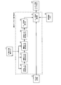
- FIG. 2 is a block diagram showing a configuration of an image decoding device according to an embodiment of the present invention, which corresponds to the image encoding device of FIG.
- the image decoding apparatus includes a bit string decoding unit 201, a block dividing unit 202, an inter prediction unit 203, an intra prediction unit 204, an encoded information storage memory 205, an inverse quantization/inverse orthogonal transform unit 206, and a decoded image signal superimposition.
- a unit 207 and a decoded image memory 208 are provided.
- the decoding process of the image decoding device in FIG. 2 corresponds to the decoding process provided inside the image coding device in FIG. 1, so the coding information storage memory 205 in FIG.
- the configurations of the orthogonal transformation unit 206, the decoded image signal superimposing unit 207, and the decoded image memory 208 are as follows: the coding information storage memory 111, the inverse quantization/inverse orthogonal transformation unit 109, and the decoded image signal of the image encoding device in FIG. It has a function corresponding to each configuration of the superimposing unit 110 and the decoded image memory 104.
- the bit stream supplied to the bit string decoding unit 201 is separated in accordance with the prescribed syntax rule.
- the bit string decoding unit 201 decodes the separated first bit string to obtain a sequence, a picture, a slice, information in units of coding blocks, and coding information in units of coding blocks. Specifically, the bit string decoding unit 201 decodes the prediction mode PredMode that determines whether the prediction is inter prediction (MODE_INTER) or intra prediction (MODE_INTRA) for each coding block.
- PredMode that determines whether the prediction is inter prediction (MODE_INTER) or intra prediction (MODE_INTRA) for each coding block.
- the bit string decoding unit 201 determines a flag for determining whether the mode is the merge mode, a merge index in the merge mode, a sub-block merge flag, and an inter prediction in the motion vector predictor mode.
- the coding information (inter prediction information) about the mode, the motion vector predictor index, the difference motion vector, the sub-block motion vector predictor flag, etc. is decoded according to the prescribed syntax, and the coding information (inter prediction information) is inter-prediction unit 203, And to the encoded information storage memory 205 via the block division unit 202.
- the prediction mode is intra prediction (MODE_INTRA)
- the coding information (intra prediction information) such as the intra prediction mode is decoded according to the prescribed syntax, and the coding information (intra prediction information) is decoded into the inter prediction unit 203 or the intra prediction unit. It is supplied to the coded information storage memory 205 via the block 204 and the block division unit 202.
- the bit string decoding unit 201 decodes the separated second bit string to calculate an orthogonally transformed/quantized residual, and supplies the orthogonally transformed/quantized residual to the inverse quantization/inverse orthogonal transforming unit 206. To do.
- the inter prediction unit 203 when the prediction mode PredMode of the coding block to be processed is inter prediction (MODE_INTER) and is the motion vector predictor mode, codes the already decoded image signal stored in the coding information storage memory 205.
- a plurality of motion vector predictor candidates are derived using the conversion information, and the derived plurality of motion vector predictor candidates are registered in a motion vector predictor candidate list to be described later.
- the inter prediction unit 203 selects, from among the plurality of motion vector predictor candidates registered in the motion vector predictor candidate list, a motion vector predictor according to the motion vector predictor index decoded and supplied by the bit string decoding unit 201, A motion vector is calculated from the differential motion vector decoded by the bit string decoding unit 201 and the selected motion vector predictor, and the calculated motion vector is stored in the coding information storage memory 205 together with other coding information.
- the coding information of the coding block supplied/stored here is a flag predFlagL0[xP][yP], predFlagL1[xP][yP], which indicates whether or not to use the prediction modes PredMode, L0 prediction, and L1 prediction.
- xP and yP are indexes indicating the position of the upper left pixel of the encoded block in the picture.
- PredMode is inter prediction (MODE_INTER) and the inter prediction mode is L0 prediction (Pred_L0)
- the flag predFlagL0 that indicates whether to use L0 prediction is 1, and the flag predFlagL1 that indicates whether to use L1 prediction Is 0.
- the flag predFlagL0 indicating whether to use L0 prediction is 0, and the flag predFlagL1 indicating whether to use L1 prediction is 1.
- the inter prediction mode is bi-prediction (Pred_BI)
- both the flag predFlagL0 indicating whether to use L0 prediction and the flag predFlagL1 indicating whether to use L1 prediction are 1.
- the prediction mode PredMode of the coding block to be processed is inter prediction (MODE_INTER) and the merge mode, a merge candidate is derived.
- a plurality of merge candidates are derived and registered in the merge candidate list described later, and registered in the merge candidate list.
- xP and yP are indexes indicating the position of the upper left pixel of the encoded block in the picture.
- the intra prediction unit 204 performs intra prediction when the prediction mode PredMode of the target coding block is intra prediction (MODE_INTRA).
- the coded information decoded by the bit string decoding unit 201 includes the intra prediction mode.
- the intra prediction unit 204 generates a predicted image signal by intra prediction from the decoded image signal stored in the decoded image memory 208 according to the intra prediction mode included in the encoded information decoded by the bit string decoding unit 201. Then, the generated predicted image signal is supplied to the decoded image signal superimposing unit 207.
- the intra prediction unit 204 corresponds to the intra prediction unit 103 of the image encoding device 100, and therefore performs the same process as the intra prediction unit 103.
- the inverse quantization/inverse orthogonal transformation unit 206 performs inverse orthogonal transformation and inverse quantization on the orthogonal transformation/quantized residual decoded by the bit string decoding unit 201, and is subjected to inverse orthogonal transformation/inverse quantization. Get the residuals.
- the decoded image signal superimposing unit 207 and the predictive image signal inter-predicted by the inter predicting unit 203 or the predictive image signal intra-predicted by the intra predicting unit 204, and the inverse orthogonal transform/inverse orthogonal transform unit 206 perform the inverse orthogonal transform/inverse orthogonal transform.
- the decoded image signal is decoded by superimposing the dequantized residual, and the decoded decoded image signal is stored in the decoded image memory 208.
- the decoded image signal superimposing unit 207 may perform filtering processing on the decoded image to reduce block distortion due to encoding, and then store the decoded image signal in the decoded image memory 208. ..
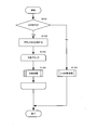
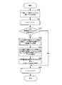
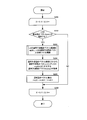
- FIG. 3 is a flowchart showing an operation of dividing an image into tree blocks and further dividing each tree block.
- the input image is divided into tree blocks of a predetermined size (step S1001).
- Each tree block is scanned in a predetermined order, that is, in raster scan order (step S1002), and the inside of the tree block to be processed is divided (step S1003).
- FIG. 7 is a flowchart showing the detailed operation of the division processing in step S1003. First, it is determined whether or not the block to be processed is divided into four (step S1101).
- the processing target block is divided into four (step S1102).
- Each block obtained by dividing the block to be processed is scanned in the Z scan order, that is, in the order of upper left, upper right, lower left, and lower right (step S1103).
- FIG. 5 is an example of the Z scan order
- 601 of FIG. 6A is an example in which the processing target block is divided into four.
- the numbers 0 to 3 in 601 of FIG. 6A indicate the order of processing.
- the division processing of FIG. 7 is recursively executed (step S1104).
- step S1105) If it is determined that the block to be processed is not divided into four, 2-3 division is performed (step S1105).
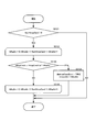
- FIG. 8 is a flowchart showing the detailed operation of the 2-3 division process of step S1105. First, it is determined whether or not the block to be processed is divided into 2-3, that is, whether to divide into 2 or 3 (step S1201).
- step S1211 the division is ended (step S1211).
- the block divided by the recursive division process is not further recursively divided.
- step S1202 it is further determined whether or not the block to be processed is further divided into two.
- step S1203 it is determined whether or not the processing target block is divided into upper and lower parts (vertical direction) (step S1203), and based on the result, the processing target block is vertically (vertical direction) divided.
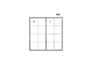
- the block to be processed is divided into two (step S1204) or the block to be processed is divided into left and right (horizontal direction) into two (step S1205).
- step S1204 the processing target block is divided into upper and lower (vertical direction) halves as indicated by 602 in FIG. 6B.
- step S1205 the processing target block is left and right (horizontal) as shown in 604 of FIG. 6D. Direction) divided into two.
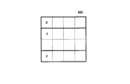
- step S1202 If it is not determined in step S1202 that the block to be processed is divided into two, that is, if it is determined that the block is to be divided into three, it is determined whether the block to be processed is divided into upper, middle, and lower (vertical direction) (step S1206). ), based on the result, the block to be processed is divided into upper, middle and lower (vertical direction) into three (step S1207), or the block to be processed is divided into left, middle and right (horizontal direction) into three (step S1208). As a result of step S1207, the processing target block is divided into upper, middle, lower (vertical direction) three divisions as shown by 603 in FIG. 6C, and as a result of step S1208, the processing target block is left as shown by 605 in FIG. 6E. Middle right (horizontal direction) divided into three.
- step S1209 After executing any of step S1204, step S1205, step S1207, and step S1208, each block obtained by dividing the block to be processed is scanned from left to right and from top to bottom (step S1209).
- the numbers 0 to 2 of 602 to 605 in FIGS. 6B to 6E indicate the order of processing.
- the 2-3 division process of FIG. 8 is recursively executed (step S1210).
- the necessity of division may be limited depending on the number of divisions or the size of the block to be processed.
- the information that restricts the necessity of division may be realized in a configuration in which information is not transmitted by making an agreement in advance between the encoding device and the decoding device, or the encoding device limits the necessity of division. It may be realized by a configuration in which the information to be determined is recorded and recorded in a bit string and transmitted to the decoding device.
- each block after the division is called the child block.
- the block division unit 202 divides a tree block by the same processing procedure as the block division unit 101 of the image encoding device 100.
- the block division unit 101 of the image coding apparatus 100 applies an optimization method such as estimation of an optimum shape by image recognition or optimization of a distortion rate to determine the optimum shape of block division, whereas the image decoding apparatus
- the block division unit 202 in 200 is different in that the block division shape is determined by decoding the block division information recorded in the bit string.
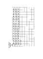
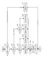
- FIG. 9 shows the syntax (syntax rule of bit string) regarding the block division of the first embodiment.
- coding_quadtree() represents the syntax for block quadrant processing.
- multi_type_tree() represents the syntax for the block division or division into three.
- each block divided into 4 is recursively divided into 4 (coding_quadtree(0), coding_quadtree(1), coding_quadtree(2), coding_quadtree(3), 0 to argument 3 corresponds to the number 601 in FIG. 6A).
- mtt_split is a flag indicating whether or not to further divide.
- mtt_split_vertical that is a flag indicating whether to divide vertically or horizontally
- mtt_split_binary that is a flag that determines whether to divide into two or three are transmitted.
- each divided block is subjected to recursive division processing (multi_type_tree(0), multi_type_tree(1), 0 to 1 of arguments are 602 or 604 of FIGS. 6B to D. Corresponds to the number.).
- multi_type_tree(0), multi_type_tree(1), multi_type_tree(2), 0 to 2 are 603 in FIG. It corresponds to the number 605 of 6E.).
- the inter prediction method according to the embodiment is implemented in the inter prediction unit 102 of the image coding apparatus of FIG. 1 and the inter prediction unit 203 of the image decoding apparatus of FIG.
- the inter prediction method according to the embodiment will be described with reference to the drawings.
- the inter-prediction method is carried out in both coding and decoding processing in coding block units.
- FIG. 16 is a diagram showing a detailed configuration of the inter prediction unit 102 of the image coding apparatus in FIG.
- the normal motion vector predictor mode deriving unit 301 derives a plurality of normal motion vector predictor candidates, selects a motion vector predictor, and calculates a difference motion vector between the selected motion vector predictor and the detected motion vector.
- the detected inter prediction mode, reference index, motion vector, and calculated differential motion vector serve as inter prediction information in the normal motion vector predictor mode. This inter prediction information is supplied to the inter prediction mode determination unit 305.
- the detailed configuration and processing of the normal motion vector predictor mode deriving unit 301 will be described later.
- the normal merge mode deriving unit 302 derives a plurality of normal merge candidates, selects a normal merge candidate, and obtains inter prediction information of the normal merge mode. This inter prediction information is supplied to the inter prediction mode determination unit 305. The detailed configuration and processing of the normal merge mode derivation unit 302 will be described later.
- the sub-block motion vector predictor mode deriving unit 303 derives a plurality of sub-block motion vector predictor candidates, selects a sub-block motion vector predictor, and calculates a difference motion vector between the selected sub-block motion vector predictor and the detected motion vector. calculate.
- the detected inter prediction mode, reference index, motion vector, and calculated differential motion vector serve as inter prediction information in the sub-block prediction motion vector mode. This inter prediction information is supplied to the inter prediction mode determination unit 305.
- the sub-block merge mode deriving unit 304 derives a plurality of sub-block merge candidates, selects a sub-block merge candidate, and obtains inter prediction information in the sub-block merge mode. This inter prediction information is supplied to the inter prediction mode determination unit 305.
- the inter prediction mode determination unit 305 is based on the inter prediction information supplied from the normal motion vector predictor mode derivation unit 301, the normal merge mode derivation unit 302, the sub block motion vector predictor mode derivation unit 303, and the sub block merge mode derivation unit 304. , Inter prediction information is determined.
- the inter prediction mode determination unit 305 supplies inter prediction information according to the determination result to the motion compensation prediction unit 306.
- the motion compensation prediction unit 306 performs inter prediction on the reference image signal stored in the decoded image memory 104 based on the determined inter prediction information. The detailed configuration and processing of the motion compensation prediction unit 306 will be described later.
- ⁇ Description of Inter Prediction Unit 203 on Decoding Side> 22 is a diagram showing a detailed configuration of the inter prediction unit 203 of the image decoding apparatus in FIG.
- the normal motion vector predictor mode deriving unit 401 derives a plurality of normal motion vector predictor candidates, selects a motion vector predictor, and calculates an addition value of the selected motion vector predictor and the decoded differential motion vector to obtain a motion vector. To do.
- the decoded inter prediction mode, reference index, and motion vector serve as inter prediction information in the normal motion vector predictor mode. This inter prediction information is supplied to the motion compensation prediction unit 406 via the switch 408. The detailed configuration and processing of the normal motion vector predictor mode deriving unit 401 will be described later.
- the normal merge mode derivation unit 402 derives a plurality of normal merge candidates, selects a normal merge candidate, and obtains inter prediction information in the normal merge mode. This inter prediction information is supplied to the motion compensation prediction unit 406 via the switch 408. The detailed configuration and processing of the normal merge mode derivation unit 402 will be described later.
- the sub-block motion vector predictor mode deriving unit 403 derives a plurality of sub-block motion vector predictor candidates, selects a sub-block motion vector predictor, and calculates the sum of the selected sub-block motion vector predictor and the decoded differential motion vector. It is calculated and used as a motion vector.
- the decoded inter prediction mode, reference index, and motion vector serve as inter prediction information in the sub-block prediction motion vector mode. This inter prediction information is supplied to the motion compensation prediction unit 406 via the switch 408.
- the sub-block merge mode deriving unit 404 derives a plurality of sub-block merge candidates, selects a sub-block merge candidate, and obtains inter prediction information in the sub-block merge mode. This inter prediction information is supplied to the motion compensation prediction unit 406 via the switch 408.
- the motion compensation prediction unit 406 performs inter prediction on the reference image signal stored in the decoded image memory 208 based on the determined inter prediction information.
- the detailed configuration and processing of the motion compensation prediction unit 406 are the same as those of the motion compensation prediction unit 306 on the encoding side.
- the normal motion vector predictor mode derivation unit 301 in FIG. 17 includes a spatial motion vector predictor candidate derivation unit 321, a temporal motion vector predictor candidate derivation unit 322, a history motion vector predictor candidate derivation unit 323, a motion vector predictor candidate supplementation unit 325, and a normal motion.
- the vector detection unit 326, the motion vector predictor candidate selection unit 327, and the motion vector subtraction unit 328 are included.
- the normal motion vector predictor mode derivation unit 401 in FIG. 23 includes a spatial motion vector predictor candidate derivation unit 421, a temporal motion vector predictor candidate derivation unit 422, a history motion vector predictor candidate derivation unit 423, a motion vector predictor candidate replenishment unit 425, and a motion predictive motion.
- a vector candidate selection unit 426 and a motion vector addition unit 427 are included.
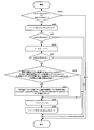
- FIG. 19 is a flowchart showing the procedure of the normal motion vector predictor mode deriving processing by the normal motion vector mode deriving section 301 on the encoding side
- FIG. 25 is the normal motion vector predictor mode deriving processing by the normal motion vector mode deriving section 401 on the decoding side. It is a flowchart which shows a procedure.
- Normal motion vector predictor (normal AMVP): Description of coding side> The normal motion vector predictor mode derivation process procedure on the encoding side will be described with reference to FIG. In the description of the processing procedure of FIG. 19, the word “normal” shown in FIG. 19 may be omitted.
- the normal motion vector detection unit 326 detects a normal motion vector for each inter prediction mode and reference index (step S100 in FIG. 19).
- the differential motion vector of the motion vector used in the inter prediction in the normal motion vector predictor mode is calculated for each of L0 and L1 (steps S101 to S106 in FIG. 19).
- the prediction mode PredMode of the target block is inter prediction (MODE_INTER) and the inter prediction mode is L0 prediction (Pred_L0)
- the motion vector predictor candidate list mvpListL0 of L0 is calculated and the motion vector predictor mvpL0 is selected.
- the differential motion vector mvdL0 of the motion vector mvL0 of L0 is calculated.
- the inter prediction mode of the block to be processed is L1 prediction (Pred_L1)
- the motion vector predictor candidate list mvpListL1 of L1 is calculated, the motion vector predictor mvpL1 is selected, and the differential motion vector mvdL1 of the motion vector mvL1 of L1 is calculated. ..
- both L0 prediction and L1 prediction are performed, a motion vector predictor candidate list mvpListL0 of L0 is calculated, and a motion vector predictor mvpL0 of L0 is selected, and L0 is calculated.
- Motion vector mvL0 differential motion vector mvdL0 is calculated, L1 motion vector predictor candidate list mvpListL1 is calculated, L1 motion vector predictor mvpL1 is calculated, and L1 motion vector mvL1 differential motion vector mvdL1 is calculated. To do.
- L0 and L1 are represented as common LX.
- the X of LX is 0, and in the process of calculating the differential motion vector of L1, the X of LX is 1.
- the other list is represented as LY.
- the motion vector predictor candidate of LX is calculated and the motion vector predictor candidate list mvpListLX of LX is constructed (step S103 of FIG. 19).
- the spatial motion vector predictor candidate deriving unit 321, the temporal motion vector predictor candidate deriving unit 322, the history motion vector predictor candidate deriving unit 323, and the motion vector predictor candidate replenishing unit 325 include a plurality of motion predictive motions.
- the motion vector candidate list mvpListLX is constructed by deriving vector candidates.
- the motion vector predictor candidate selection unit 327 selects the motion vector predictor mvpLX of LX from the motion vector predictor candidate list of LX mvpListLX (step S104 in FIG. 19).
- the motion vector predictor candidate list mvpListLX one certain element (i-th element counting from 0) is represented as mvpListLX[i].
- Each difference motion vector that is the difference between the motion vector mvLX and each motion vector predictor candidate mvpListLX[i] stored in the motion vector predictor candidate list mvpListLX is calculated.
- a code amount when the difference motion vectors are encoded is calculated for each element (predictive motion vector candidate) of the motion vector predictor candidate list mvpListLX. Then, among the elements registered in the motion vector predictor candidate list mvpListLX, the motion vector predictor candidate mvpListLX[i] that minimizes the code amount for each motion vector predictor candidate is selected as the motion vector predictor mvpLX, and Get the index i.
- the motion vector predictor represented by a smaller index i in the motion vector predictor candidate list mvpListLX When there are a plurality of motion vector predictor candidates having the smallest amount of generated code in the motion vector predictor candidate list mvpListLX, the motion vector predictor represented by a smaller index i in the motion vector predictor candidate list mvpListLX.
- the candidate mvpListLX[i] of is selected as the optimum motion vector predictor mvpLX and its index i is acquired.
- Normal motion vector predictor (normal AMVP): Description of decoding side>
- the normal motion vector predictor mode processing procedure on the decoding side will be described with reference to FIG.
- the spatial motion vector predictor candidate derivation unit 421, the temporal motion vector predictor candidate derivation unit 422, the history motion vector predictor candidate derivation unit 423, and the motion vector predictor candidate supplementation unit 425 are used in inter prediction in the normal motion vector predictor mode.
- the motion vector is calculated for each of L0 and L1 (steps S201 to S206 in FIG. 25).
- the prediction motion vector candidate list mvpListL0 of L0 is calculated, and the prediction motion is calculated.
- the vector mvpL0 is selected and the motion vector mvL0 of L0 is calculated.
- the inter prediction mode of the block to be processed is L1 prediction (Pred_L1)
- the motion vector predictor candidate list mvpListL1 for L1 is calculated, the motion vector predictor mvpL1 is selected, and the motion vector mvL1 for L1 is calculated.
- both L0 prediction and L1 prediction are performed, a motion vector predictor candidate list mvpListL0 of L0 is calculated, and a motion vector predictor mvpL0 of L0 is selected and L0 is calculated.
- Motion vector mvL0 of L1 the motion vector predictor candidate list mvpListL1 of L1 is calculated, the motion vector predictor mvpL1 of L1 is calculated, and the motion vector mvL1 of L1 is calculated.
- L0 and L1 are represented as common LX.
- LX represents an inter prediction mode used for inter prediction of a coding block to be processed.
- X is 0 in the process of calculating the motion vector of L0, and X is 1 in the process of calculating the motion vector of L1.
- the other reference list is expressed as LY.
- the motion vector predictor candidate of LX is calculated to construct the motion vector predictor candidate list mvpListLX of LX (step S203 of FIG. 25).
- the spatial motion vector predictor candidate deriving unit 421, the temporal motion vector predictor candidate deriving unit 422, the history motion vector predictor candidate deriving unit 423, and the motion vector predictor candidate replenishing unit 425 include a plurality of motion predictive motions.
- Vector candidates are calculated and a motion vector predictor candidate list mvpListLX is constructed.
- the motion vector predictor candidate selection unit 426 selects a motion vector predictor candidate mvpListLX[mvpIdxLX] corresponding to the motion vector predictor index mvpIdxLX decoded and supplied from the motion vector predictor candidate list mvpListLX by the bit string decoding unit 201.
- the predicted motion vector mvpLX thus obtained is extracted (step S204 in FIG. 25).
- the motion vector mvLX of LX is calculated as (step S205 in FIG. 25).
- FIG. 20 is a normal motion vector predictor mode derivation having a common function with the normal motion vector predictor mode deriving unit 301 of the image encoding device and the normal motion vector predictor mode deriving unit 401 of the image decoding device according to the embodiment of the present invention. It is a flow chart showing a processing procedure of processing.
- the normal motion vector predictor mode deriving unit 301 and the normal motion vector predictor mode deriving unit 401 include a motion vector predictor candidate list mvpListLX.
- the motion vector predictor candidate list mvpListLX has a list structure, and is provided with a storage area for storing, as elements, a motion vector predictor vector index indicating a location in the motion vector predictor candidate list and a motion vector predictor candidate corresponding to the index. ..
- the number of the motion vector predictor index starts from 0, and the motion vector predictor candidates are stored in the storage area of the motion vector predictor candidate list mvpListLX.
- 0 is set to a variable numCurrMvpCand indicating the number of motion vector predictor candidates registered in the motion vector predictor candidate list mvpListLX.
- the spatial motion vector predictor candidate derivation units 321 and 421 derive motion vector predictor candidates from the block adjacent to the left side.
- the inter prediction information of the block adjacent to the left side A0 or A1 in FIG. 11
- a flag indicating whether or not the motion vector predictor candidate is available, and the motion vector, the reference index, etc. are referred to
- the vector mvLXA is derived, and the derived mvLXA is added to the motion vector predictor candidate list mvpListLX (step S301 in FIG. 20). Note that X is 0 for L0 prediction and X is 1 for L1 prediction (the same applies hereinafter).
- the spatial motion vector predictor candidate derivation units 321 and 421 derive motion vector predictor candidates from blocks adjacent to the upper side.
- the inter prediction information of the block (B0, B1, or B2 in FIG. 11) adjacent to the upper side that is, a flag indicating whether or not the motion vector predictor candidate can be used, the motion vector, the reference index, and the like are referred to.
- the motion vector predictor mvLXB is derived, and if the derived mvLXA and mvLXB are not equal, mvLXB is added to the motion vector predictor candidate list mvpListLX (step S302 in FIG. 20).
- a reference index refIdxN (N indicates A or B, and so on).
- the temporal motion vector predictor candidate derivation units 322 and 422 derive motion vector predictor candidates from blocks in a picture whose time is different from that of the current picture to be processed.
- a flag availableFlagLXCol indicating whether or not a motion vector predictor candidate of a coded block of a picture at a different time is available
- a motion vector mvLXCol, a reference index refIdxCol, and a reference list listCol are derived
- mvLXCol is a motion vector predictor candidate. It is added to the list mvpListLX (step S303 in FIG. 20).
- temporal motion vector predictor candidate derivation units 322 and 422 can be omitted for each sequence (SPS), picture (PPS), or slice unit.
- the historical motion vector predictor candidate derivation units 323 and 423 add the historical motion vector predictor candidates registered in the historical motion vector predictor list HmvpCandList to the motion vector predictor candidate list mvpListLX. (Step S304 of FIG. 20). Details of the registration processing procedure in step S304 will be described later with reference to the flowchart in FIG.
- the motion vector predictor candidate supplementing units 325 and 425 add motion vector predictor candidates having a predetermined value such as (0, 0) until the motion vector predictor candidate list mvpListLX is satisfied (S305 in FIG. 20).
- the normal merge mode derivation unit 302 in FIG. 18 includes a spatial merge candidate derivation unit 341, a temporal merge candidate derivation unit 342, an average merge candidate derivation unit 344, a history merge candidate derivation unit 345, a merge candidate replenishment unit 346, and a merge candidate selection unit 347. including.
- the normal merge mode derivation unit 402 of FIG. 24 includes a spatial merge candidate derivation unit 441, a temporal merge candidate derivation unit 442, an average merge candidate derivation unit 444, a history merge candidate derivation unit 445, a merge candidate replenishment unit 446, and a merge candidate selection unit 447. including.
- FIG. 21 illustrates a procedure of a normal merge mode derivation process having a common function with the normal merge mode derivation unit 302 of the image encoding device and the normal merge mode derivation unit 402 of the image decoding device according to the embodiment of the present invention. It is a flowchart.
- the normal merge mode derivation unit 302 and the normal merge mode derivation unit 402 include a merge candidate list mergeCandList.
- the merge candidate list mergeCandList has a list structure, and is provided with a merge index indicating the location inside the merge candidate list and a storage area for storing merge candidates corresponding to the index as elements. The number of the merge index starts from 0, and the merge candidate is stored in the storage area of the merge candidate list mergeCandList.
- the merge candidates of the merge index i registered in the merge candidate list mergeCandList will be represented by mergeCandList[i].
- the merge candidate list mergeCandList can register at least 6 merge candidates (inter prediction information). Further, 0 is set to the variable numCurrMergeCand indicating the number of merge candidates registered in the merge candidate list mergeCandList.
- the block to be processed is processed from the coding information stored in the coding information storage memory 111 of the image coding device or the coding information storage memory 205 of the image decoding device.
- the spatial merge candidates from the blocks (B1, A1, B0, A0, B2 in FIG. 11) adjacent to are derived in the order of B1, A1, B0, A0, B2, and the derived spatial merge candidates are merge candidates. It is registered in the list mergeCandList (step S401 in FIG. 21).
- N indicating any one of B1, A1, B0, A0, B2 or the time merge candidate Col is defined.
- the flag predFlagL0N and the L1 prediction flag predFlagL1N and the motion vector mvL0N of L0 and the motion vector mvL1N of L1 which show whether L1 prediction are performed are derived.
- the merge candidate is derived without referring to the inter prediction information of the block included in the coding block to be processed
- the inter prediction information of the block included in the coding block to be processed is derived.
- a spatial merge candidate using is not derived.
- the temporal merge candidate derivation unit 342 and the temporal merge candidate derivation unit 442 derive temporal merge candidates from pictures at different times and register the derived temporal merge candidates in the merge candidate list mergeCandList (FIG. 21).
- Step S402 A flag availableFlagCol indicating whether or not the temporal merge candidate is available, an L0 prediction flag predFlagL0Col indicating whether or not L0 prediction of the temporal merge candidate is performed and an L1 prediction flag predFlagL1Col and L0 indicating whether or not L1 prediction is performed.
- the motion vector mvL0Col of L1 and the motion vector mvL1Col of L1 are derived.
- the processes of the temporal merge candidate derivation unit 342 and the temporal merge candidate derivation unit 442 can be omitted for each sequence (SPS), picture (PPS), or slice.
- the history merge candidate derivation unit 345 and the history merge candidate derivation unit 445 register the history motion vector predictor candidates registered in the history motion vector predictor candidate list HmvpCandList in the merge candidate list mergeCandList (step S403 in FIG. 21). .. If the number of merge candidates numCurrMergeCand registered in the merge candidate list mergeCandList is smaller than the maximum number of merge candidates MaxNumMergeCand, the number of merge candidates numCurrMergeCand registered in the merge candidate list mergeCandList is the maximum number of merge candidates MaxNumMergeCand as the upper limit.
- the history merge candidate is derived and registered in the merge candidate list mergeCandList.
- the average merge candidate derivation unit 344 and the average merge candidate derivation unit 444 derive the average merge candidate from the merge candidate list mergeCandList and add the derived average merge candidate to the merge candidate list mergeCandList (step in FIG. 21). S404). If the number of merge candidates numCurrMergeCand registered in the merge candidate list mergeCandList is smaller than the maximum number of merge candidates MaxNumMergeCand, the number of merge candidates numCurrMergeCand registered in the merge candidate list mergeCandList is the maximum number of merge candidates MaxNumMergeCand as the upper limit.
- the average merge candidate is derived and registered in the merge candidate list mergeCandList.
- the average merge candidate has a new motion vector obtained by averaging the motion vectors of the first merge candidate and the second merge candidate registered in the merge candidate list mergeCandList for each L0 prediction and L1 prediction. It is a good candidate for merging.
- the merge candidate supplementing unit 346 and the merge candidate supplementing unit 446 when the number of merge candidates numCurrMergeCand registered in the merge candidate list mergeCandList is smaller than the maximum number of merge candidates MaxNumMergeCand, it is registered in the merge candidate list mergeCandList.
- the number of merge candidates numCurrMergeCand that is present derives additional merge candidates with the maximum number of merge candidates MaxNumMergeCand as the upper limit, and registers them in the merge candidate list mergeCandList (step S405 in FIG. 21).
- a merge candidate whose motion vector has a value of (0, 0) and whose prediction mode is L0 prediction (Pred_L0) is added.
- a merge candidate in which the prediction mode in which the motion vector has a value of (0,0) is bi-prediction (Pred_BI) is added.
- the reference index when adding a merge candidate is different from the reference index already added.
- the merge candidate selection unit 347 and the merge candidate selection unit 447 select merge candidates from the merge candidates registered in the merge candidate list mergeCandList.
- the merging candidate selecting unit 347 on the encoding side selects the merging candidate by calculating the code amount and the distortion amount, and selects the merging index indicating the merging candidate selected, the inter prediction information of the merging candidate, and the inter prediction mode judging unit. It is supplied to the motion compensation prediction unit 306 via 305.
- the merge candidate selection unit 447 on the decoding side selects a merge candidate based on the decoded merge index and supplies the selected merge candidate to the motion compensation prediction unit 406.
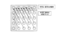
- the normal merge mode derivation unit 302 and the normal merge mode derivation unit 402 when the size (product of width and height) of a certain coding block is less than 32, merge candidates are derived in the parent block of the coding block. Then, the merge candidates derived in the parent block are used in all the child blocks. However, it is limited to the case where the size of the parent block is 32 or more and is within the screen.
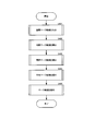
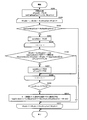
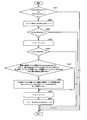
- FIG. 26 is a flowchart for explaining the procedure of the process of initializing and updating the history motion vector predictor candidate list.
- history motion vector predictor candidate list HmvpCandList is updated in the encoded information storage memory 111 and the encoded information storage memory 205.
- a history motion vector predictor candidate list update unit may be installed in the inter prediction unit 102 and the inter prediction unit 203 to update the history motion vector predictor candidate list HmvpCandList.
- the history motion vector predictor candidate list HmvpCandList is initialized at the beginning of the slice, and when the normal motion vector predictor mode or the normal merge mode is selected by the prediction method determination unit 105 on the encoding side, the history motion vector predictor candidate list HmvpCandList is set.
- the decoding side updates the history prediction motion vector candidate list HmvpCandList on the decoding side when the prediction information decoded by the bit string decoding unit 201 is the normal motion vector predictor mode or the normal merge mode.
- the inter prediction information candidate hMvpCandList the inter prediction information candidate hMvpCand.
- the reference index refIdxL0 of L0 and the reference index refIdxL1 of L1 the reference index refIdxL0 indicating whether L0 prediction is performed
- the L1 prediction flag predFlagL1 indicating whether L1 prediction is performed
- the motion vector mvL0 of L0 and the motion vector mvL1 of L1 are included.
- inter prediction information candidates are included. If inter prediction information having the same value as hMvpCand exists, that element is deleted from the history motion vector predictor candidate list HmvpCandList. On the other hand, if there is no inter prediction information having the same value as the inter prediction information candidate hMvpCand, the top element of the historical motion vector predictor candidate list HmvpCandList is deleted, and the inter prediction information candidate is added at the end of the historical motion vector predictor list HmvpCandList. Add hMvpCand.
- the number of elements of the history motion vector predictor candidate list HmvpCandList provided in the coding information storage memory 111 on the coding side and the coding information storage memory 205 on the decoding side of the present invention is 6.
- the history motion vector predictor candidate list HmvpCandList is initialized in slice units (step S2101 in FIG. 26).
- the history motion vector predictor candidate is added to all the elements of the motion vector predictor motion vector candidate list HmvpCandList at the beginning of the slice, and the number of motion vector predictor motion vector candidates registered in the motion vector predictor motion vector candidate list HmvpCandList is set to 6 for the value of NumHmvpCand. Set.
- empty all the elements of the history motion vector predictor candidate list HmvpCandList at the beginning of the slice, and set the number of history motion vector predictor candidates (current number of candidates) NumHmvpCand registered in the motion vector predictor candidate list HmvpCandList to It may be set to 0.
- the initialization of the history motion vector predictor candidate list HmvpCandList is performed in slice units (the first coding block of a slice), but it may be performed in picture units, tile units, or tree block row units.
- FIG. 38 is a table showing an example of historical motion vector predictor candidates added by the initialization of the historical motion vector predictor candidate list HmvpCandList.
- the information is added to the history motion vector predictor candidate list HmvpCandList as the history motion vector predictor candidates, and the history motion vector predictor candidate list is filled with the history candidates.
- the history motion vector predictor index hMvpIdx starts from (the number of motion vector predictor candidates NumHmvpCand-1), and the reference index refIdxLX (X is 0 or 1) ranges from 0 to (the number of reference pictures numRefIdx-1). Set a value that is incremented by 1. After that, duplication between the historical motion vector predictor candidates is permitted, and the reference index refIdxLX is set to a value of 0. All the values are set in the number of historical motion vector predictor candidates NumHmvpCand and the value of the number of historical motion vector predictor candidates NumHmvpCand is set to a fixed value to eliminate invalid historical motion vector predictor candidates.
- the history motion vector predictor candidate list in slice units can be filled with the history motion vector predictor candidates. Further, by filling the history motion vector predictor candidate list in slice units with the history motion vector predictor candidates, the number of history motion vector predictor candidates can be treated as a fixed value.
- the history merge candidate derivation process can be simplified.
- the value of the motion vector is generally (0, 0), which has a high selection probability, but any other value may be used as long as it is a predetermined value.
- the coding efficiency of the differential motion vector may be improved by setting a value such as (4,4), (0,32), (-128,0), or a plurality of predetermined values may be set to set the differential motion vector. The coding efficiency of may be improved.
- the history motion vector predictor index hMvpIdx starts from (the number of motion vector predictor motion vector candidates NumHmvpCand-1), and the reference index refIdxLX (X is 0 or 1) ranges from 0 to (the number of reference pictures numRefIdx-1). Although the values are set to be incremented by one, the history motion vector predictor index hMvpIdx may be started from 0.
- FIG. 39 is a table showing another example of the historical motion vector predictor candidates added by the initialization of the historical motion vector predictor list HmvpCandList.
- the value of the reference index refIdxLX (X is 0 or 1) or the motion vector mvLXHmvp (X is 0 or 1) is set so that each element of the historical motion vector predictor list HmvpCandList does not overlap with each other.
- the inter-prediction information of which is different is added as the maximum number of elements as the history motion vector predictor candidates, and the history motion vector predictor candidate list is filled.
- the history motion vector predictor index hMvpIdx starts from (the number of motion vector predictor candidates NumHmvpCand-1), and the reference index refIdxLX (X is 0 or 1) ranges from 0 to (the number of reference pictures numRefIdx-1). Set a value that is incremented by 1. After that, the reference index refIdxLX is set to 0, and the motion vector mvLXHmvp having a value different from (0, 0) is added as a history prediction motion vector candidate. All the values are set in the number of historical motion vector predictor candidates NumHmvpCand and the value of the number of historical motion vector predictor candidates NumHmvpCand is set to a fixed value to eliminate invalid historical motion vector predictor candidates.
- the history merge candidate in the normal merge mode derivation unit 302 which will be described later, that is performed in units of coding blocks.
- the processing of the merge candidate supplementation unit 346 after the derivation unit 345 can be omitted, and the processing amount can be reduced.
- the absolute value of each component of the motion vector mvLXHmvp is set to 0 or 1, but the absolute value of each component of the motion vector mvLXHmvp may be set to be larger than 1 as long as history prediction motion vector candidates do not overlap with each other. ..
- the history motion vector predictor index hmvpIdx starts from (the number of motion vector predictor motion vectors NumHmvpCand-1), and 0 to (the number of reference pictures numRefIdx-1) for the reference index refIdxLX (X is 0 or 1). Although the values are set to be incremented by one, the history motion vector predictor index hMvpIdx may be started from 0.
- FIG. 40 is a table showing another example of the historical motion vector predictor candidates added by the initialization of the historical motion vector predictor list HmvpCandList.
- the reference index refIdxLX is 0 and the inter prediction information with different motion vector mvLXHmvp values is set as the history motion vector predictor candidates so that the elements of the motion vector predictor candidate list HmvpCandList do not overlap with each other.
- the history motion vector predictor index hMvpIdx is started from (the number of history motion vector predictor candidates NumHmvpCand-1), the reference index refIdxLX (X is 0 or 1) is 0, and the motion vector mvLXHmvp is different.
- All the values are set in the number of historical motion vector predictor candidates NumHmvpCand and the value of the number of historical motion vector predictor candidates NumHmvpCand is set to a fixed value to eliminate invalid historical motion vector predictor candidates.
- the absolute value of each component of the motion vector mvLXHmvp is set to a power of 0, 1 or 2, but if the reference index is 0 and no overlap between the historical prediction motion vector candidates occurs, the absolute value of each component of the motion vector mvLXHmvp
- the value may be a power of a value other than 2, such as 3, 4, or any other value.
- the history motion vector predictor index hMvpIdx is started from (the number of motion vector predictor motion vector candidates NumHmvpCand-1), the reference index refIdxLX (X is 0 or 1) is 0, and the motion vector mvLXHmvp is set to different inter prediction information.
- the history motion vector predictor index hMvpIdx may be started from 0.
- step S2104 It is determined whether or not the inter prediction information candidate hMvpCand to be registered exists (step S2104 in FIG. 26).
- the inter prediction information is set as an inter prediction information candidate hMvpCand to be registered.
- the prediction method determination unit 105 on the encoding side determines the intra prediction mode, the sub-block prediction motion vector mode, or the sub-block merge mode, or the decoding-side bit string decoding unit 201 determines the intra prediction mode, the sub-block prediction motion vector mode
- the history motion vector predictor candidate list HmvpCandList is not updated, and the inter prediction information candidate hMvpCand to be registered does not exist. If the inter prediction information candidate hMvpCand to be registered does not exist, steps S2105 to S2106 are skipped (step S2104 of FIG. 26: NO).
- the processing from step S2105 is performed (step S2104 in FIG. 26: YES).
- FIG. 27 is a flowchart of the same element confirmation processing procedure.
- the value of the number of historical motion vector predictor NumHmvpCand is 0 (step S2121 in FIG. 27: NO)
- the historical motion vector predictor candidate list HmvpCandList is empty and the same candidate does not exist, so steps S2122 to S2125 in FIG. 27 are skipped. Then, the same element confirmation processing procedure ends.
- step S2123 is repeated from the history motion vector predictor index hMvpIdx of 0 to NumHmvpCand-1 (step of FIG. 27). S2122 to S2125). First, it is compared whether or not the hMvpIdxth element HmvpCandList[hMvpIdx] counting from 0 in the history motion vector predictor list is the same as the inter prediction information candidate hMvpCand (step S2123 in FIG. 27). If they are the same (step S2123 in FIG.
- step S2123 in FIG. 27: NO hMvpIdx is incremented by 1, and if the history motion vector predictor index hMvpIdx is NumHmvpCand-1 or less, the processing from step S2123 is performed.
- FIG. 28 is a flowchart of the element shift/addition processing procedure of the history motion vector predictor candidate list HmvpCandList in step S2106 of FIG. First, it is determined whether an element stored in the history motion vector predictor candidate list HmvpCandList is removed and then a new element is added, or whether a new element is added without removing the element.
- step S2141 it compares whether or not TRUE (true) or NumHmvpCand is 6 with a flag “identicalCandExist” indicating whether the same candidate exists (step S2141 in FIG. 28).
- the flag indicating whether the same candidate exists is TRUE (true) or the current number of candidates NumHmvpCand satisfies the condition of 6 (YES in step S2141 of FIG. 28)
- the history motion vector predictor candidate list HmvpCandList Add the new element after removing the element stored in. Set the initial value of index i to the value of removeIdx + 1. From this initial value to NumHmvpCand, the element shift processing of step S2143 is repeated.
- Step S2142 to S2144 in FIG. 28 By copying the element of HmvpCandList[ i ] to HmvpCandList[ i - 1 ], the element is shifted forward (step S2143 in FIG. 28) and i is incremented by 1 (steps S2142 to S2144 in FIG. 28). Subsequently, the inter prediction information candidate hMvpCand is added to the (NumHmvpCand-1)th HmvpCandList[NumHmvpCand-1] counting from 0 corresponding to the end of the history prediction motion vector candidate list (step S2145 in FIG. 28), and the main history prediction is performed.
- the element shift/addition processing of the motion vector candidate list HmvpCandList ends.
- the condition of TRUE (true) and NumHmvpCand of 6 is satisfied in the flag “identicalCandExist” indicating whether the same candidate exists (step S2141 in FIG. 28: NO)
- it is stored in the history motion vector predictor candidate list HmvpCandList.
- the inter-prediction information candidate hMvpCand is added to the end of the history motion vector predictor candidate list without excluding the elements described (step S2146 in FIG. 28).
- the end of the history motion vector predictor candidate list is the NumHmvpCand th HmvpCandList[NumHmvpCand] counted from 0.
- NumHmvpCand is incremented by 1, and the element shift and addition processing of this history motion vector predictor candidate list HmvpCandList are terminated.
- FIG. 31 is a diagram illustrating an example of update processing of the history motion vector predictor candidate list.
- the history prediction motion vector candidate list HmvpCandList that has registered six elements (inter prediction information)
- it is compared with new inter prediction information in order from the front element of the history prediction motion vector candidate list HmvpCandList.
- FIG. 31A if the new element has the same value as the third element HMVP2 from the top of the history motion vector predictor candidate list HmvpCandList, the element HMVP2 is deleted from the history motion vector predictor list HmvpCandList and the subsequent element HMVP3...
- HMVP5 is shifted (copied) forward one by one, a new element is added to the end of the history motion vector predictor candidate list HmvpCandList (FIG. 31B), and the history motion vector predictor candidate list HmvpCandList is updated (FIG. 31C). ).
- FIG. 29 is a flowchart for explaining the procedure of the history motion vector predictor candidate derivation process.
- step S2201 in FIG. 29 If the current number of motion vector predictor candidates numCurrMvpCand is greater than or equal to the maximum number of elements (here, 2) in the motion vector predictor candidate list mvpListLX, or if the number of historical motion vector predictor candidates is 0 in the value of NumHmvpCand (step S2201 in FIG. 29). 29), the processing of steps S2202 to S2209 in FIG. 29 is omitted, and the history motion vector predictor candidate derivation processing procedure ends.
- the maximum number of elements here, 2
- the number of historical motion vector predictor candidates is 0 in the value of NumHmvpCand
- steps S2203 to S2208 of FIG. 29 are repeated until the index i is 1 to 4 and the number of historical motion vector predictor candidates numCheckedHMVPCand, whichever is smaller (steps S2202 to S2209 of FIG. 29). If the current number of motion vector predictor candidates numCurrMvpCand is 2 or more, which is the maximum number of elements of the motion vector predictor candidate list mvpListLX (step S2203: NO in FIG. 29), the processes in steps S2204 to S2209 in FIG. The history motion vector predictor candidate derivation process procedure ends.
- step S2203 YES in FIG. 29
- the processes after step S2204 in FIG. 29 are performed.
- steps S2205 to S2207 are performed for Y of 0 and 1 (L0 and L1), respectively (steps S2204 to S2208 of FIG. 29).
- the current number numCurrMvpCand of motion vector predictor candidates is 2 or more, which is the maximum number of elements of the motion vector predictor candidate list mvpListLX (step S2205 of FIG. 29: NO)
- the processes of steps S2206 to S2209 of FIG. 29 are omitted, This history motion vector predictor candidate derivation processing procedure is ended.
- step S2205 YES in FIG. 29
- the process from step S2206 onward in FIG. 29 is performed.
- Step S2206 the LY motion vector of the history motion vector predictor candidate HmvpCandList[NumHmvpCand - i] is added to the numCurrMvpCand th element mvpListLX[numCurrMvpCand] counting from 0 in the motion vector predictor list (step in FIG. 29).
- step S2207 the number of current motion vector predictor candidates numCurrMvpCand is incremented by 1.
- the additional process of step S2207 is skipped.
- steps S2205 to S2207 in FIG. 29 are performed in L0 and L1 (steps S2204 to S2208 in FIG. 29).
- the index i is incremented by 1, and when the index i is 4 or less than the number NumHmvpCand of the number of history motion vector predictor candidates, whichever is smaller, the processes in and after step S2203 are performed again (steps S2202 to S2209 in FIG. 29).
- step S404 in FIG. 21 which is a process common to the history merge candidate derivation unit 345 of the encoding-side normal merge mode derivation unit 302 and the history merge candidate derivation unit 445 of the decoding-side normal merge mode derivation unit 402.
- a method of deriving a history merge candidate from the history merge candidate list HmvpCandList, which is a procedure, will be described in detail.
- FIG. 30 is a flowchart for explaining the history merge candidate derivation processing procedure.
- initialization processing is performed (step S2301 in FIG. 30).
- the initial value of the index hMvpIdx is set to 1, and the additional processing from step S2303 to step S2310 in FIG. 30 is repeated from this initial value to NumHmvpCand (steps S2302 to S2311 in FIG. 30). If the number of elements registered in the current merge candidate list numCurrMergeCand is not less than (maximum merge candidate number MaxNumMergeCand-1), merge candidates have been added to all elements in the merge candidate list, so this history merge candidate derivation The process ends (NO in step S2303 of FIG. 30).
- step S2304 When the number numCurrMergeCand of the elements registered in the current merge candidate list is (maximum merge candidate number MaxNumMergeCand-1) or less, the processing from step S2304 is performed. A value of FALSE (false) is set in sameMotion (step S2304 in FIG. 30). Subsequently, the initial value of the index i is set to 0, and the processes of steps S2306 and S2307 of FIG. 30 are performed from this initial value to numOrigMergeCand-1 (S2305 to S2308 of FIG. 30).
- FALSE false
- the same value of the merge candidate means that the merge candidate has the same value when all the constituent elements (inter prediction mode, reference index, motion vector) of the merge candidate have the same value. If the merge candidates have the same value and isPruned[i] is FALSE (YES in step S2306 in FIG. 30), both sameMotion and isPruned[i] are set to TRUE (step S2307 in FIG. 30). If the values are not the same (NO in step S2306 in FIG. 30), the process in step S2307 is skipped. When the iterative process from step S2305 to step S2308 in FIG. 30 is completed, it is compared whether or not sameMotion is FALSE (step S2309 in FIG. 30).
- the (NumHmvpCand-hMvpIdx)th element HmvpCandList[NumHmvpCand-hMvpIdx] counting from 0 in the motion vector candidate list is added, and numCurrMergeCand is incremented by 1 (step S2310 in FIG. 30).
- the index hMvpIdx is incremented by 1 (step S2302 of FIG. 30), and steps S2302 to S2311 of FIG. 30 are repeated.
- the motion compensation prediction unit 306 acquires the position and size of the block currently subjected to prediction processing in encoding. Further, the motion compensation prediction unit 306 acquires the inter prediction information from the inter prediction mode determination unit 305. A reference index and a motion vector are derived from the acquired inter prediction information, and the reference picture specified by the reference index in the decoded image memory 104 is moved from the same position as the image signal of the prediction block by the amount of the motion vector. After obtaining the image signal, the prediction signal is generated.
- the inter prediction mode in inter prediction is prediction from a single reference picture such as L0 prediction or L1 prediction
- the prediction signal acquired from one reference picture is used as the motion compensation prediction signal
- the inter prediction mode is BI.
- the prediction mode is prediction from two reference pictures, such as prediction
- a weighted average of the prediction signals acquired from the two reference pictures is used as the motion compensation prediction signal
- the motion compensation prediction signal is determined as the prediction method. It is supplied to the section 105.
- the weighted average ratio of bi-prediction is set to 1:1, but the weighted average may be performed using another ratio. For example, the closer the picture interval between the picture to be predicted and the reference picture is, the larger the weighting ratio may be. Further, the weighting ratio may be calculated using a correspondence table between the combination of picture intervals and the weighting ratio.
- the motion compensation prediction unit 406 has the same function as the motion compensation prediction unit 306 on the encoding side.
- the motion compensation prediction unit 406 outputs the inter prediction information from the normal motion vector predictor mode derivation unit 401, the normal merge mode derivation unit 402, the sub block motion vector predictor mode derivation unit 403, and the sub block merge mode derivation unit 404 to the switch 408. To get through.
- the motion compensation prediction unit 406 supplies the obtained motion compensation prediction signal to the decoded image signal superimposing unit 207.
- ⁇ About inter prediction mode> The process of performing prediction from a single reference picture is defined as uni-prediction, and in the case of uni-prediction, either one of the two reference pictures registered in the reference lists L0 and L1 called L0 prediction or L1 prediction is used. Make a prediction.
- FIG. 32 shows a case of uni-prediction, and the reference picture (RefL0Pic) of L0 is at a time before the picture to be processed (CurPic).
- FIG. 33 shows a case where the reference picture of the L0 prediction in the uni-prediction is at a time after the picture to be processed.
- the L0 prediction reference picture in FIGS. 32 and 33 may be replaced with the L1 prediction reference picture (RefL1Pic) to perform single prediction.
- FIG. 34 shows a case where the reference picture for bi-prediction and L0 prediction is at a time before the processing target picture, and the L1 prediction reference picture is at a time after the processing target picture.
- FIG. 35 illustrates a case where bi-prediction reference pictures for L0 prediction and reference pictures for L1 prediction are at a time before the picture to be processed.
- FIG. 36 shows a case in which bi-prediction reference pictures for L0 prediction and reference pictures for L1 prediction are at times after the picture to be processed.
- L0 prediction and L1 prediction may be performed using the same reference picture. Note that the determination as to whether the motion-compensated prediction is performed by uni-prediction or bi-prediction is made based on information (for example, a flag) indicating whether or not L0 prediction is used and whether or not L1 prediction is used. It
- ⁇ About reference index> In the embodiment of the present invention, in order to improve the accuracy of motion compensation prediction, it is possible to select the optimum reference picture from a plurality of reference pictures in motion compensation prediction. Therefore, the reference picture used in the motion compensation prediction is used as a reference index, and the reference index is encoded in the bitstream together with the differential motion vector.
- the motion compensation prediction unit 306 when the inter prediction mode determination unit 305 selects the inter prediction information by the normal motion vector predictor mode derivation unit 301, as shown in the inter prediction unit 102 on the encoding side in FIG. Acquires this inter prediction information from the inter prediction mode determination unit 305, derives the inter prediction mode, reference index, and motion vector of the block currently being processed, and generates a motion compensation prediction signal.
- the generated motion compensation prediction signal is supplied to the prediction method determination unit 105.
- the motion vector predictor mode deriving unit 401 acquires the inter prediction information, derives the inter prediction mode, the reference index, and the motion vector of the currently processed block, and generates the motion compensation prediction signal.
- the generated motion compensation prediction signal is supplied to the decoded image signal superimposing unit 207.
- ⁇ Motion compensation processing based on normal merge mode> In the motion compensation prediction unit 306, when the inter prediction mode determination unit 305 selects the inter prediction information by the normal merge mode derivation unit 302, as shown in the inter prediction unit 102 on the encoding side in FIG. This inter prediction information is acquired from the inter prediction mode determination unit 305, the inter prediction mode, the reference index, and the motion vector of the currently processed block are derived, and the motion compensation prediction signal is generated. The generated motion compensation prediction signal is supplied to the prediction method determination unit 105.
- the motion compensation prediction unit 406 when the switch 408 is connected to the normal merge mode derivation unit 402 in the decoding process as shown in the inter prediction unit 203 on the decoding side in FIG. 22, the normal merge mode.
- the inter-prediction information is obtained by the derivation unit 402, the inter-prediction mode, reference index, and motion vector of the block currently being processed are derived, and a motion-compensated prediction signal is generated.
- the generated motion compensation prediction signal is supplied to the decoded image signal superimposing unit 207.
- the motion compensation prediction unit 306 As shown in the inter prediction unit 102 on the coding side in FIG. 16, when the inter prediction mode determination unit 305 selects the inter prediction information by the sub block prediction motion vector mode derivation unit 303. For this, the inter prediction information is acquired from the inter prediction mode determination unit 305, the inter prediction mode, the reference index, and the motion vector of the currently processed block are derived to generate a motion compensation prediction signal. The generated motion compensation prediction signal is supplied to the prediction method determination unit 105.
- the motion compensation prediction unit 406 as shown in the inter prediction unit 203 on the decoding side in FIG. 22, when the switch 408 is connected to the sub-block motion vector predictor mode derivation unit 403 during the decoding process,
- the inter-prediction motion vector mode derivation unit 403 acquires inter-prediction information, derives the inter-prediction mode, reference index, and motion vector of the currently processed block, and generates a motion-compensated prediction signal.
- the generated motion compensation prediction signal is supplied to the decoded image signal superimposing unit 207.
- ⁇ Motion compensation processing based on sub-block merge mode> In the motion compensation prediction unit 306, when the inter prediction mode determination unit 305 selects the inter prediction information by the sub block merge mode derivation unit 304, as shown in the inter prediction unit 102 on the encoding side in FIG.
- the inter prediction information is acquired from the inter prediction mode determination unit 305, the inter prediction mode, the reference index, and the motion vector of the currently processed block are derived, and the motion compensation prediction signal is generated.
- the generated motion compensation prediction signal is supplied to the prediction method determination unit 105.
- the motion compensation prediction unit 406 as shown in the inter prediction unit 203 on the decoding side in FIG. 22, when the switch 408 is connected to the sub block merge mode derivation unit 404 in the decoding process, the sub block The inter prediction information obtained by the merge mode derivation unit 404 is acquired, the inter prediction mode, the reference index, and the motion vector of the block currently being processed are derived, and the motion compensation prediction signal is generated. The generated motion compensation prediction signal is supplied to the decoded image signal superimposing unit 207.
- motion compensation by an affine model can be used based on the following flags.
- the following flags are reflected in the following flags based on the inter prediction condition determined by the inter prediction mode determination unit 305 in the encoding process, and are encoded in the bitstream.
- ⁇ sps_affine_enabled_flag indicates whether motion compensation using an affine model can be used in inter prediction. If sps_affine_enabled_flag is 0, the motion compensation by the affine model is suppressed in sequence units. Also, inter_affine_flag and cu_affine_type_flag are not transmitted in the CU (coding block) syntax of the coded video sequence. If sps_affine_enabled_flag is 1, motion compensation by an affine model can be used in the coded video sequence.
- ⁇ sps_affine_type_flag indicates whether motion compensation using a 6-parameter affine model can be used in inter prediction. If sps_affine_type_flag is 0, the motion compensation is not performed by the 6-parameter affine model. Also, cu_affine_type_flag is not transmitted in the CU syntax of the coded video sequence. If sps_affine_type_flag is 1, motion compensation by a 6-parameter affine model can be used in a coded video sequence. If sps_affine_type_flag does not exist, it shall be 0.
- inter_affine_flag 1 in the CU currently being processed
- the affine model is used to generate the motion compensation prediction signal of the CU currently being processed. Motion compensation is used. If inter_affine_flag is 0, the affine model is not used for the CU currently being processed. If inter_affine_flag does not exist, it shall be 0.
- a reference index or motion vector is derived in sub-block units, so a motion-compensated prediction signal is generated using the reference index or motion vector that is the processing target in sub-block units.
- the 4-parameter affine model is a mode in which the motion vector of a sub-block is derived from the four parameters of the horizontal and vertical components of the motion vector of each of the two control points, and motion compensation is performed in sub-block units.
- the order in which the elements (candidates) of the history motion vector predictor candidate list are referred to is the same in the normal motion vector predictor mode and the normal merge mode.
- the order of reference when using the history motion vector predictor candidate list is the reverse of that of the first embodiment, as shown in FIG.
- the order is the same as that of the first embodiment, as shown in FIG. That is, the order of referring to the candidates included in the history motion vector predictor candidate list is reversed (reverse order) in the normal motion vector predictor mode and the normal merge mode.
- the elements in the history motion vector predictor candidate list are added to the motion vector predictor candidate list in order from the oldest element, and in the normal merge mode, the elements in the history motion vector predictor candidate list are The new elements will be added to the motion vector predictor candidate list in order.
- the inter prediction information used by the inter prediction in the current block is set as the inter prediction information candidate hMvpCand to be registered, and the history prediction motion vector candidate list HmvpCandList is used as the history that has been used in the past. Register with.
- the history motion vector predictor candidate list has a list structure capable of storing six elements, and the first-in first-out FIFO (First-In, First Out) method in which the elements stored first are sequentially extracted. Is the basic storage operation.
- the maximum number of elements that can be stored in the HmvpCandList is described as 6 as an agreement on the encoding side and the decoding side, but it is not particularly limited and may be 6 or more. Further, the maximum number of elements that can be stored in the HmvpCandList may be five or less.
- the HmvpCandList may be configured to have the maximum number of elements equivalent to the maximum number of elements of the inter prediction information candidates, such as the maximum number of elements of the motion vector predictor candidate list mvpListLX, the maximum number of merge candidates, and the maximum number of candidate subblock merges. Further, the HmvpCandList may be configured so as to be linked to the maximum number of elements of inter prediction information candidates in each mode.
- HmvpCandList The maximum number of elements of this HmvpCandList may be included in the syntax element of the bitstream so that it can be transmitted from the encoding side to the decoding side.
- HmvpCandList can store 6 elements from position 0, which is the beginning of the list, to position 5, which is the end of the list, and can fill the elements from position 0 to position 5 in order. it can.
- the positions 0 to 5 are managed as the history motion vector predictor index hMvpIdx.
- position 0 can be expressed as hMVpIdx[0]
- position 5 can be expressed as hMVpIdx[5].
- the number of storage elements of the HmvpCandList is managed by NumHmvpCand, and the increase/decrease of storage elements is managed in the range of 0 to 6, which is the maximum number of elements.
- HmvpCandList Detailed description of adding a new element while the maximum number of elements is stored in HmvpCandList.
- the inter-prediction information candidate hMvpCand is to be newly registered as a history
- the element at position 0 that is the head is deleted, and the position of each element is shifted one by one in the head direction.
- the number of storage elements is reduced by one as shown in FIG. 43, so that a new element can be stored in the last position 5. Therefore, by storing the inter prediction information candidate hMvpCand at the end position 5, a new element is added to the HmvpCandList as shown in FIG.
- FIG. 47 is a diagram illustrating a case where the history motion vector predictor candidate list HmvpCandList is configured to be used while referring in the order opposite to the reference order of the normal merge mode in the normal motion vector predictor mode of the second embodiment, It is a flow chart explaining a history prediction motion vector candidate derivation processing procedure.
- step S2601 in FIG. 47 When the number numCurrMvpCand of the current motion vector predictor candidates is equal to or larger than the maximum number of elements (here, 2) of the motion vector predictor candidate list mvpListLX, or when the number NumHmvpCand of the number of history motion vector predictor candidates is 0 (step S2601 in FIG. 47). NO), the processing of steps S2602 to S2609 of FIG. 47 is omitted, and the history motion vector predictor candidate derivation processing procedure ends.
- the maximum number of elements here, 2
- NumHmvpCand of the number of history motion vector predictor candidates is 0 (step S2601 in FIG. 47).
- steps S2603 to S2608 of FIG. 47 are repeated until the index i is 0 to 4, and the number of historical motion vector predictor candidates NumHmvpCand, whichever is smaller, is subtracted from 1 (step S2602 to FIG. 47). S2609). If the current number of motion vector predictor candidates numCurrMvpCand is 2 or more, which is the maximum number of elements of the motion vector predictor candidate list mvpListLX (NO in step S2603 of FIG. 47 ), the processes of steps S2604 to S2609 of FIG. The history motion vector predictor candidate derivation process procedure ends.
- step S2604 If the current number numCurrMvpCand of motion vector predictor candidates is smaller than 2, which is the maximum number of elements in the motion vector predictor candidate list mvpListLX (YES in step S2603 of FIG. 47 ), the process of step S2604 and subsequent steps of FIG. 47 is performed.
- steps S2605 to S2607 are performed for indexes Y of 0 and 1 (L0 and L1), respectively (steps S2604 to S2608 of FIG. 47).
- the number numCurrMvpCand of the current motion vector predictor candidates is 2 or more, which is the maximum number of elements of the motion vector predictor candidate list mvpListLX (NO in step S2605 of FIG. 47 )
- the history motion vector predictor candidate derivation process procedure ends.
- step S2606 When the current number numCurrMvpCand of motion vector predictor candidates is smaller than 2, which is the maximum number of elements of the motion vector predictor candidate list mvpListLX (YES in step S2605 of FIG. 47 ), the process of step S2606 and subsequent steps of FIG. 47 is performed.
- the LY motion vector of the history motion vector predictor candidate HmvpCandList[i] is added to the numCurrMvpCand th element mvpListLX[numCurrMvpCand ] counting from 0 in the motion vector predictor list (step S2607 in FIG. 47).
- step S2607 the addition process of step S2607 is skipped.
- steps S2605 to S2607 in FIG. 47 are performed in L0 and L1 (steps S2604 to S2608 in FIG. 47).
- the index i is incremented by 1 (steps S2602 and S2609 in FIG. 47), and when the index i is equal to or less than the value obtained by subtracting 1 from the smaller one of 4 and the number of historical motion vector predictor candidates NumHmvpCand, the processing of step S2603 and thereafter is performed again. Is performed (steps S2602 to S2609 in FIG. 47).
- elements that are added first (old elements) in the history motion vector predictor candidate list are referenced in order and added to the motion vector predictor candidate list.
- ⁇ Modification 1> A history reference flag indicating that the reference order of the history motion vector predictor candidate list is used as in the present embodiment is introduced, and the reference order of the first embodiment and the reference order of the present embodiment are combined. It may be configured to be switched.
- the history reference flag may be included in the syntax element of the bitstream and transmitted to the decoding side, and the decoding side may acquire the bitstream having the history reference flag as the syntax element and be able to decode the bitstream.
- ⁇ Modification 2> In the present embodiment, in the normal motion vector predictor mode, the history motion vector predictor candidate list is referred to one by one in the order of elements 0 to 5 as shown in FIG. 46. In the normal merge mode, as shown in FIG.
- references were made one by one in the order of element 5 to element 0 of the history motion vector predictor candidate list, but this is limited to this if the order of referring to the motion vector predictor candidate list is different between the normal motion vector predictor mode and the normal merge mode. Not done.
- the elements 0 to 2 are referred to, and in the normal merge mode, the element 5 to the element 1 are referred to.
- the numbers referred to may be different. In this case, it is preferable to increase the number of references in the normal merge mode in which the number of candidates is large. Further, in the normal merge mode, the starting point may be changed so as to refer to the elements 4 to 0.
- the reference order when using the history motion vector predictor candidate list is set to a reference order different from the normal motion vector predictor mode, so that each mode can be changed. You will be able to adopt suitable candidates.
- the normal motion vector predictor mode for encoding the differential motion vector is selected, a motion vector different from the situation around the target block for encoding is often required. Therefore, by searching the history motion vector predictor candidate list and using elements that are considered to have a relatively low correlation different from the most recent one, that is, the oldest elements stored first, as candidates, the normal motion vector predictor mode is set.
- a candidate suitable for can contribute to the improvement of coding efficiency.
- the higher the correlation around the target block to be encoded the higher the coding efficiency. Therefore, searching the history motion vector predictor candidate list, the element that is considered to have a relatively high correlation with the closest one, that is, By sequentially using new elements stored later as candidates, it is possible to contribute to the improvement of coding efficiency by candidates suitable for the normal merge mode.
- the bitstream output by the image encoding device has a specific data format so that the bitstream can be decoded according to the encoding method used in the embodiments. There is. Also, the image decoding device corresponding to this image encoding device can decode the bit stream of this specific data format.
- a wired or wireless network is used to exchange a bitstream between the image encoding device and the image decoding device, even if the bitstream is converted into a data format suitable for the transmission mode of the communication path and then transmitted. Good.
- a bit stream output from the image coding device is converted into coded data in a data format suitable for the transmission mode of the communication path and transmitted to the network, and a bit stream is generated by receiving the coded data from the network.
- a receiving device that restores to the image decoding device and supplies the image decoding device with the receiving device.
- the transmission device includes a memory that buffers the bitstream output by the image encoding device, a packet processing unit that packetizes the bitstream, and a transmission unit that transmits the packetized encoded data via a network.
- the receiving device receives a packetized encoded data via a network, a memory for buffering the received encoded data, a packet processing of the encoded data to generate a bit stream, and an image decoding And a packet processing unit provided to the device.
- a display unit may be added by adding a display unit for displaying an image decoded by the image decoding device to the configuration.
- the display unit reads the decoded image signal generated by the decoded image signal superimposing unit 207 and stored in the decoded image memory 208, and displays it on the screen.
- an image pickup unit may be added to the configuration, and the picked-up image may be input to the image coding device to form the image pickup device.
- the imaging unit inputs the captured image signal to the block division unit 101.
- FIG. 37 shows an example of the hardware configuration of the encoding/decoding device of this embodiment.
- the encoding/decoding device includes the configurations of the image encoding device and the image decoding device according to the embodiment of the present invention.
- the encoding/decoding device 9000 includes a CPU 9001, a codec IC 9002, an I/O interface 9003, a memory 9004, an optical disk drive 9005, a network interface 9006, and a video interface 9009, and each unit is connected by a bus 9010.
- the image encoding unit 9007 and the image decoding unit 9008 are typically implemented as a codec IC 9002.
- the image encoding process of the image encoding device according to the embodiment of the present invention is executed by the image encoding unit 9007, and the image decoding process of the image decoding device according to the embodiment of the present invention is performed by the image decoding unit 9008.
- the I/O interface 9003 is realized by a USB interface, for example, and is connected to an external keyboard 9104, mouse 9105, and the like.
- the CPU 9001 controls the encoding/decoding device 9000 to execute an operation desired by the user, based on the user operation input via the I/O interface 9003.
- the user's operations using the keyboard 9104, mouse 9105, etc. include selection of which function of encoding or decoding is to be executed, setting of encoding quality, bitstream input/output destination, image input/output destination, and the like.
- the optical disc drive 9005 When the user desires an operation of reproducing an image recorded on the disc recording medium 9100, the optical disc drive 9005 reads a bitstream from the inserted disc recording medium 9100 and outputs the read bitstream via the bus 9010. It is sent to the image decoding unit 9008 of the codec IC 9002.
- the image decoding unit 9008 executes the image decoding processing in the image decoding apparatus according to the embodiment of the present invention on the input bitstream, and sends the decoded image to the external monitor 9103 via the video interface 9009.
- the encoding/decoding device 9000 has a network interface 9006 and can be connected to an external distribution server 9106 and a mobile terminal 9107 via the network 9101.
- the network interface 9006 sets the input from the input disk recording medium 9100. Instead of reading the bitstream, the bitstream is acquired from the network 9101. Further, when the user desires to reproduce the image recorded in the memory 9004, the image decoding processing in the image decoding device according to the embodiment of the present invention is performed on the bitstream recorded in the memory 9004. To do.
- the video interface 9009 inputs the image from the camera 9102, and via the bus 9010, the image encoding unit 9007 of the codec IC 9002. Send to.
- the image coding unit 9007 executes the image coding process in the image coding apparatus according to the embodiment of the present invention on the image input via the video interface 9009 to create a bitstream. Then, the bit stream is sent to the memory 9004 via the bus 9010.
- the optical disc drive 9005 writes the bitstream to the inserted disc recording medium 9100.
- Such a hardware configuration is realized, for example, by replacing the codec IC 9002 with the image encoding unit 9007 or the image decoding unit 9008.
- the above-mentioned processing relating to encoding and decoding may be realized as a transmission, storage, and reception device using hardware, and is also stored in a ROM (read only memory), a flash memory, or the like. It may be realized by firmware or software such as a computer.
- the firmware program and the software program may be provided by being recorded in a recording medium readable by a computer or the like, provided from a server through a wired or wireless network, or terrestrial or satellite digital broadcasting data broadcasting. May be provided as.
- 100 image encoding device 101 block division unit, 102 inter prediction unit, 103 intra prediction unit, 104 decoded image memory, 105 prediction method determination unit, 106 residual generation unit, 107 orthogonal transform/quantization unit, 108 bit string encoding Part, 109 dequantization/inverse orthogonal transformation part, 110 decoded image signal superposition part, 111 encoded information storage memory, 200 image decoding device, 201 bit string decoding part, 202 block division part, 203 inter prediction part 204 intra prediction part, 205 coded information storage memory 206 dequantization/inverse orthogonal transformation unit, 207 decoded image signal superposition unit, 208 decoded image memory.
Abstract
Priority Applications (10)
| Application Number | Priority Date | Filing Date | Title |
|---|---|---|---|
| KR1020237032496A KR20230143622A (ko) | 2018-12-28 | 2019-12-19 | 화상 부호화 장치, 화상 부호화 방법, 화상 부호화 프로그램, 화상 복호 장치, 화상 복호 방법 및 화상 복호 프로그램 |
| EP19901806.0A EP3905685B1 (fr) | 2018-12-28 | 2019-12-19 | Dispositif de codage d'image, procédé de codage d'image, programme de codage d'image, dispositif de décodage d'image, procédé de décodage d'image et programme de décodage d'image |
| MX2021007753A MX2021007753A (es) | 2018-12-28 | 2019-12-19 | Dispositivo de codificacion de imagenes, metodo de codificacion de imagenes, dispositivo de decodificacion de imagenes y metodo de decodificacion de imagenes. |
| CN201980044849.XA CN112470476A (zh) | 2018-12-28 | 2019-12-19 | 图像编码装置、图像编码方法、图像编码程序、图像解码装置、图像解码方法及图像解码程序 |
| US17/269,977 US11516500B2 (en) | 2018-12-28 | 2019-12-19 | Picture coding device, picture coding method, and picture coding program, picture decoding device, picture decoding method, and picture decoding program |
| KR1020207037256A KR102583807B1 (ko) | 2018-12-28 | 2019-12-19 | 화상 부호화 장치, 화상 부호화 방법, 화상 부호화 프로그램, 화상 복호 장치, 화상 복호 방법 및 화상 복호 프로그램 |
| RU2021118210A RU2770863C1 (ru) | 2018-12-28 | 2019-12-19 | Устройство кодирования кадров, способ кодирования кадров, устройство декодирования кадров и способ декодирования кадров |
| BR112021012418-7A BR112021012418A2 (pt) | 2018-12-28 | 2019-12-19 | Dispositivo de codificação de imagem, método de codificação de imagem, dispositivo de decodificação de imagem e método de decodificação de imagem |
| ZA2021/04334A ZA202104334B (en) | 2018-12-28 | 2021-06-23 | Image encoding device, image encoding method, image encoding program, image decoding device, image decoding method, and image decoding program |
| US17/963,016 US11979597B2 (en) | 2018-12-28 | 2022-10-10 | Picture coding device, picture coding method, and picture coding program, picture decoding device, picture decoding method, and picture decoding program |
Applications Claiming Priority (4)
| Application Number | Priority Date | Filing Date | Title |
|---|---|---|---|
| JP2018-247413 | 2018-12-28 | ||
| JP2018247413 | 2018-12-28 | ||
| JP2019-082764 | 2019-04-24 | ||
| JP2019082764 | 2019-04-24 |
Related Child Applications (2)
| Application Number | Title | Priority Date | Filing Date |
|---|---|---|---|
| US17/269,977 A-371-Of-International US11516500B2 (en) | 2018-12-28 | 2019-12-19 | Picture coding device, picture coding method, and picture coding program, picture decoding device, picture decoding method, and picture decoding program |
| US17/963,016 Continuation US11979597B2 (en) | 2018-12-28 | 2022-10-10 | Picture coding device, picture coding method, and picture coding program, picture decoding device, picture decoding method, and picture decoding program |
Publications (1)
| Publication Number | Publication Date |
|---|---|
| WO2020137814A1 true WO2020137814A1 (fr) | 2020-07-02 |
Family
ID=71128608
Family Applications (1)
| Application Number | Title | Priority Date | Filing Date |
|---|---|---|---|
| PCT/JP2019/049864 WO2020137814A1 (fr) | 2018-12-28 | 2019-12-19 | Dispositif de codage d'image, procédé de codage d'image, programme de codage d'image, dispositif de décodage d'image, procédé de décodage d'image et programme de décodage d'image |
Country Status (10)
| Country | Link |
|---|---|
| US (1) | US11516500B2 (fr) |
| EP (1) | EP3905685B1 (fr) |
| JP (4) | JP6763469B1 (fr) |
| KR (2) | KR102583807B1 (fr) |
| CN (2) | CN112954364A (fr) |
| BR (1) | BR112021012418A2 (fr) |
| MX (1) | MX2021007753A (fr) |
| RU (1) | RU2770863C1 (fr) |
| WO (1) | WO2020137814A1 (fr) |
| ZA (1) | ZA202104334B (fr) |
Families Citing this family (2)
| Publication number | Priority date | Publication date | Assignee | Title |
|---|---|---|---|---|
| KR102583807B1 (ko) * | 2018-12-28 | 2023-09-26 | 가부시키가이샤 제이브이씨 켄우드 | 화상 부호화 장치, 화상 부호화 방법, 화상 부호화 프로그램, 화상 복호 장치, 화상 복호 방법 및 화상 복호 프로그램 |
| US11800122B2 (en) * | 2021-08-17 | 2023-10-24 | Mediatek Inc. | Video processing apparatus using internal prediction buffer that is shared by multiple coding tools for prediction |
Citations (2)
| Publication number | Priority date | Publication date | Assignee | Title |
|---|---|---|---|---|
| JPH09172644A (ja) | 1995-10-18 | 1997-06-30 | Sharp Corp | アフィン変換による動き補償フレーム間予測方式を用いた動画像符号化・復号化装置 |
| WO2020003278A1 (fr) * | 2018-06-29 | 2020-01-02 | Beijing Bytedance Network Technology Co., Ltd. | Mise à jour de table de consultation : fifo, à contrainte fifo |
Family Cites Families (25)
| Publication number | Priority date | Publication date | Assignee | Title |
|---|---|---|---|---|
| EP1274253A3 (fr) | 1995-08-29 | 2005-10-12 | Sharp Kabushiki Kaisha | Dispositif de codage vidéo et dispositif de décodage vidéo à prédiction intertrame avec compensation du mouvement |
| WO2011095260A1 (fr) * | 2010-02-05 | 2011-08-11 | Telefonaktiebolaget L M Ericsson (Publ) | Gestion de vecteurs de mouvement prédits candidats |
| WO2012097377A1 (fr) * | 2011-01-14 | 2012-07-19 | General Instrument Corporation | Mode de fusion spatiale et temporelle conjointe de blocs pour hevc |
| US9485518B2 (en) * | 2011-05-27 | 2016-11-01 | Sun Patent Trust | Decoding method and apparatus with candidate motion vectors |
| EP3879832A1 (fr) * | 2011-05-31 | 2021-09-15 | JVCKENWOOD Corporation | Dispositif, procédé et programme de codage d'image animée, ainsi que dispositif, procédé et programme de décodage d'image animée |
| PL3422714T3 (pl) * | 2011-06-30 | 2021-05-31 | JVC Kenwood Corporation | Urządzenie do kodowania obrazu, sposób kodowania obrazu, program do kodowania obrazu, urządzenie do dekodowania obrazu, sposób dekodowania obrazu i program do dekodowania obrazu |
| TWI575945B (zh) * | 2011-09-28 | 2017-03-21 | Jvc Kenwood Corp | A motion picture decoding apparatus, a motion picture decoding method, and a recording medium |
| CA2841058C (fr) * | 2011-12-16 | 2021-03-23 | Panasonic Corporation | Procede de codage d'image video, dispositif de codage d'image video, procede de decodage d'image video, dispositif de decodage d'image video et dispositif de codage et de decodage d'image video |
| US20130188715A1 (en) * | 2012-01-09 | 2013-07-25 | Qualcomm Incorporated | Device and methods for merge list reordering in video coding |
| US9838710B2 (en) * | 2014-12-23 | 2017-12-05 | Intel Corporation | Motion estimation for arbitrary shapes |
| US10448010B2 (en) | 2016-10-05 | 2019-10-15 | Qualcomm Incorporated | Motion vector prediction for affine motion models in video coding |
| WO2018141416A1 (fr) * | 2017-02-06 | 2018-08-09 | Huawei Technologies Co., Ltd. | Codeur et décodeur vidéo de partitionnement prédictif |
| US11606575B2 (en) * | 2018-07-10 | 2023-03-14 | Qualcomm Incorporated | Multiple history based non-adjacent MVPs for wavefront processing of video coding |
| US10491902B1 (en) * | 2018-07-16 | 2019-11-26 | Tencent America LLC | Method and apparatus for history-based motion vector prediction |
| US10362330B1 (en) * | 2018-07-30 | 2019-07-23 | Tencent America LLC | Combining history-based motion vector prediction and non-adjacent merge prediction |
| BR112021002604A2 (pt) * | 2018-08-13 | 2021-05-04 | Lg Electronics Inc. | método de predição inter baseado no vetor de movimento baseado em histórico e dispositivo do mesmo |
| US11336914B2 (en) * | 2018-08-16 | 2022-05-17 | Qualcomm Incorporated | History-based candidate list with classification |
| GB2590310B (en) * | 2018-09-12 | 2023-03-22 | Beijing Bytedance Network Tech Co Ltd | Conditions for starting checking HMVP candidates depend on total number minus K |
| US11212550B2 (en) * | 2018-09-21 | 2021-12-28 | Qualcomm Incorporated | History-based motion vector prediction for affine mode |
| MX2021003682A (es) * | 2018-10-04 | 2021-05-31 | Lg Electronics Inc | Metodo de codificacion de imagen a base de historial, y aparato del mismo. |
| US11051034B2 (en) * | 2018-10-08 | 2021-06-29 | Qualcomm Incorporated | History-based motion vector predictor |
| CN111147855A (zh) * | 2018-11-02 | 2020-05-12 | 北京字节跳动网络技术有限公司 | 几何分割预测模式与其他工具之间的协调 |
| CN116684635A (zh) | 2018-12-06 | 2023-09-01 | Lg电子株式会社 | 编解码设备和数据发送设备 |
| KR102583807B1 (ko) * | 2018-12-28 | 2023-09-26 | 가부시키가이샤 제이브이씨 켄우드 | 화상 부호화 장치, 화상 부호화 방법, 화상 부호화 프로그램, 화상 복호 장치, 화상 복호 방법 및 화상 복호 프로그램 |
| US10979716B2 (en) * | 2019-03-15 | 2021-04-13 | Tencent America LLC | Methods of accessing affine history-based motion vector predictor buffer |
-
2019
- 2019-12-19 KR KR1020207037256A patent/KR102583807B1/ko active IP Right Grant
- 2019-12-19 CN CN202110120447.2A patent/CN112954364A/zh active Pending
- 2019-12-19 MX MX2021007753A patent/MX2021007753A/es unknown
- 2019-12-19 RU RU2021118210A patent/RU2770863C1/ru active
- 2019-12-19 BR BR112021012418-7A patent/BR112021012418A2/pt unknown
- 2019-12-19 EP EP19901806.0A patent/EP3905685B1/fr active Active
- 2019-12-19 KR KR1020237032496A patent/KR20230143622A/ko not_active Application Discontinuation
- 2019-12-19 CN CN201980044849.XA patent/CN112470476A/zh active Pending
- 2019-12-19 US US17/269,977 patent/US11516500B2/en active Active
- 2019-12-19 WO PCT/JP2019/049864 patent/WO2020137814A1/fr unknown
- 2019-12-27 JP JP2019239373A patent/JP6763469B1/ja active Active
-
2020
- 2020-09-09 JP JP2020151409A patent/JP6936448B2/ja active Active
-
2021
- 2021-06-23 ZA ZA2021/04334A patent/ZA202104334B/en unknown
- 2021-08-24 JP JP2021136171A patent/JP7251579B2/ja active Active
- 2021-09-10 JP JP2021147602A patent/JP2022008367A/ja active Pending
Patent Citations (2)
| Publication number | Priority date | Publication date | Assignee | Title |
|---|---|---|---|---|
| JPH09172644A (ja) | 1995-10-18 | 1997-06-30 | Sharp Corp | アフィン変換による動き補償フレーム間予測方式を用いた動画像符号化・復号化装置 |
| WO2020003278A1 (fr) * | 2018-06-29 | 2020-01-02 | Beijing Bytedance Network Technology Co., Ltd. | Mise à jour de table de consultation : fifo, à contrainte fifo |
Non-Patent Citations (4)
| Title |
|---|
| LI ZHANG , KAI ZHANG , HONGBIN LIU , YUE WANG , PENGWEI ZHAO , DINGKUN HONG : "CE4: History-based Motion Vector Prediction (Test 4.4.7) ", JOINT VIDEO EXPERTS TEAM (JVET) OF ITU-T SG 16 WP 3 AND ISO/IEC JTC 1/SC 29/ WG 11, JVET-L0266-V2, 12TH MEETING, no. JVET-L0266_v2, 2 October 2018 (2018-10-02), Macao , CN, pages 1 - 6, XP030194308 * |
| LI ZHANG , KAI ZHANG , HONGBIN LIU , YUE WANG , PENGWEI ZHAO , DINGKUN HONG : "CE4-related: History-based Motion Vector Prediction", 11. JVET MEETING; 20180711 - 20180718; LJUBLJANA; (THE JOINT VIDEO EXPLORATION TEAM OF ISO/IEC JTC1/SC29/WG11 AND ITU-T SG.16 ), no. JVET-K0104_v5, 18 July 2018 (2018-07-18), Ljubljana, SI, pages 1 - 7, XP030200019 * |
| TOSHIYASU SUGIO , TAKAHIRO NISHI : "On MVP candidate list for AMVP/Merge", 9. JCT-VC MEETING; 100. MPEG MEETING; 27-4-2012 - 7-5-2012; GENEVA; (JOINT COLLABORATIVE TEAM ON VIDEO CODING OF ISO/IEC JTC1/SC29/WG11 AND ITU-T SG.16 ), no. JCTVC-I0134, 16 April 2012 (2012-04-16), Geneva, CH, pages 1 - 6, XP030111897 * |
| ZHANG LI; ZHANG KAI; LIU HONGBIN; CHUANG HSIAO CHIANG; WANG YUE; XU JIZHENG; ZHAO PENGWEI; HONG DINGKUN: "History-based Motion Vector Prediction in Versatile Video Coding", 2019 DATA COMPRESSION CONFERENCE (DCC), 6 March 2019 (2019-03-06), pages 43 - 52, XP033548557, DOI: 10.1109/DCC.2019.00012 * |
Also Published As
| Publication number | Publication date |
|---|---|
| US20230031244A1 (en) | 2023-02-02 |
| KR102583807B1 (ko) | 2023-09-26 |
| EP3905685A1 (fr) | 2021-11-03 |
| MX2021007753A (es) | 2021-08-05 |
| JP2020205624A (ja) | 2020-12-24 |
| BR112021012418A2 (pt) | 2021-09-08 |
| JP6936448B2 (ja) | 2021-09-15 |
| RU2770863C1 (ru) | 2022-04-22 |
| US11516500B2 (en) | 2022-11-29 |
| JP7251579B2 (ja) | 2023-04-04 |
| JP2022008367A (ja) | 2022-01-13 |
| JP6763469B1 (ja) | 2020-09-30 |
| CN112954364A (zh) | 2021-06-11 |
| KR20210013200A (ko) | 2021-02-03 |
| CN112470476A (zh) | 2021-03-09 |
| US20210352313A1 (en) | 2021-11-11 |
| EP3905685B1 (fr) | 2024-03-20 |
| JP2022003774A (ja) | 2022-01-11 |
| ZA202104334B (en) | 2023-01-25 |
| JP2020182208A (ja) | 2020-11-05 |
| KR20230143622A (ko) | 2023-10-12 |
| EP3905685A4 (fr) | 2022-09-21 |
Similar Documents
| Publication | Publication Date | Title |
|---|---|---|
| JP7445936B2 (ja) | 画像符号化装置、画像符号化方法、画像符号化プログラム、画像復号装置、画像復号方法及び画像復号プログラム | |
| JP7409365B2 (ja) | 画像符号化装置、画像符号化方法、画像符号化プログラム、画像復号装置、画像復号方法及び画像復号プログラム | |
| JP6866919B2 (ja) | 動画像復号装置、動画像復号方法、動画像復号プログラム、動画像符号化装置、動画像符号化方法及び動画像符号化プログラム | |
| WO2020137890A1 (fr) | Dispositif de codage d'image, procédé de codage d'image, programme de codage d'image, dispositif de décodage d'image, procédé de décodage d'image, et programme de décodage d'image | |
| WO2020137848A1 (fr) | Dispositif de codage d'image animée, procédé de codage d'image animée, programme de codage d'image animée, dispositif de décodage d'image animée, procédé de décodage d'image animée, et programme de décodage d'image animée | |
| JP7251579B2 (ja) | 画像符号化装置、画像符号化方法、画像符号化プログラム、画像復号装置、画像復号方法及び画像復号プログラム | |
| JP7060773B2 (ja) | 画像復号装置、画像復号方法及び画像復号プログラム | |
| WO2020137857A1 (fr) | Dispositif de codage d'image, procédé de codage d'image, programme de codage d'image, dispositif de décodage d'image, procédé de décodage d'image et programme de décodage d'image | |
| TW202415072A (zh) | 影像編碼裝置、影像編碼方法、影像編碼程式、影像解碼裝置、影像解碼方法、影像解碼程式、儲存方法及送訊方法 |
Legal Events
| Date | Code | Title | Description |
|---|---|---|---|
| 121 | Ep: the epo has been informed by wipo that ep was designated in this application |
Ref document number: 19901806 Country of ref document: EP Kind code of ref document: A1 |
|
| ENP | Entry into the national phase |
Ref document number: 20207037256 Country of ref document: KR Kind code of ref document: A |
|
| NENP | Non-entry into the national phase |
Ref country code: DE |
|
| REG | Reference to national code |
Ref country code: BR Ref legal event code: B01A Ref document number: 112021012418 Country of ref document: BR |
|
| ENP | Entry into the national phase |
Ref document number: 2019901806 Country of ref document: EP Effective date: 20210728 |
|
| ENP | Entry into the national phase |
Ref document number: 112021012418 Country of ref document: BR Kind code of ref document: A2 Effective date: 20210623 |