WO2020137599A1 - 回転体の動翼およびディスク - Google Patents
回転体の動翼およびディスク Download PDFInfo
- Publication number
- WO2020137599A1 WO2020137599A1 PCT/JP2019/048856 JP2019048856W WO2020137599A1 WO 2020137599 A1 WO2020137599 A1 WO 2020137599A1 JP 2019048856 W JP2019048856 W JP 2019048856W WO 2020137599 A1 WO2020137599 A1 WO 2020137599A1
- Authority
- WO
- WIPO (PCT)
- Prior art keywords
- blade
- blade root
- contact
- root
- contact surface
- Prior art date
- Legal status (The legal status is an assumption and is not a legal conclusion. Google has not performed a legal analysis and makes no representation as to the accuracy of the status listed.)
- Ceased
Links
Images




Classifications
-
- F—MECHANICAL ENGINEERING; LIGHTING; HEATING; WEAPONS; BLASTING
- F01—MACHINES OR ENGINES IN GENERAL; ENGINE PLANTS IN GENERAL; STEAM ENGINES
- F01D—NON-POSITIVE DISPLACEMENT MACHINES OR ENGINES, e.g. STEAM TURBINES
- F01D5/00—Blades; Blade-carrying members; Heating, heat-insulating, cooling or antivibration means on the blades or the members
- F01D5/02—Blade-carrying members, e.g. rotors
- F01D5/06—Rotors for more than one axial stage, e.g. of drum or multiple disc type; Details thereof, e.g. shafts, shaft connections
-
- F—MECHANICAL ENGINEERING; LIGHTING; HEATING; WEAPONS; BLASTING
- F01—MACHINES OR ENGINES IN GENERAL; ENGINE PLANTS IN GENERAL; STEAM ENGINES
- F01D—NON-POSITIVE DISPLACEMENT MACHINES OR ENGINES, e.g. STEAM TURBINES
- F01D5/00—Blades; Blade-carrying members; Heating, heat-insulating, cooling or antivibration means on the blades or the members
- F01D5/30—Fixing blades to rotors; Blade roots ; Blade spacers
- F01D5/32—Locking, e.g. by final locking blades or keys
-
- F—MECHANICAL ENGINEERING; LIGHTING; HEATING; WEAPONS; BLASTING
- F01—MACHINES OR ENGINES IN GENERAL; ENGINE PLANTS IN GENERAL; STEAM ENGINES
- F01D—NON-POSITIVE DISPLACEMENT MACHINES OR ENGINES, e.g. STEAM TURBINES
- F01D5/00—Blades; Blade-carrying members; Heating, heat-insulating, cooling or antivibration means on the blades or the members
- F01D5/30—Fixing blades to rotors; Blade roots ; Blade spacers
- F01D5/3007—Fixing blades to rotors; Blade roots ; Blade spacers of axial insertion type
-
- F—MECHANICAL ENGINEERING; LIGHTING; HEATING; WEAPONS; BLASTING
- F04—POSITIVE - DISPLACEMENT MACHINES FOR LIQUIDS; PUMPS FOR LIQUIDS OR ELASTIC FLUIDS
- F04D—NON-POSITIVE-DISPLACEMENT PUMPS
- F04D29/00—Details, component parts, or accessories
- F04D29/26—Rotors specially for elastic fluids
- F04D29/32—Rotors specially for elastic fluids for axial flow pumps
- F04D29/321—Rotors specially for elastic fluids for axial flow pumps for axial flow compressors
- F04D29/322—Blade mountings
-
- F—MECHANICAL ENGINEERING; LIGHTING; HEATING; WEAPONS; BLASTING
- F04—POSITIVE - DISPLACEMENT MACHINES FOR LIQUIDS; PUMPS FOR LIQUIDS OR ELASTIC FLUIDS
- F04D—NON-POSITIVE-DISPLACEMENT PUMPS
- F04D29/00—Details, component parts, or accessories
- F04D29/26—Rotors specially for elastic fluids
- F04D29/32—Rotors specially for elastic fluids for axial flow pumps
- F04D29/34—Blade mountings
-
- F—MECHANICAL ENGINEERING; LIGHTING; HEATING; WEAPONS; BLASTING
- F05—INDEXING SCHEMES RELATING TO ENGINES OR PUMPS IN VARIOUS SUBCLASSES OF CLASSES F01-F04
- F05D—INDEXING SCHEME FOR ASPECTS RELATING TO NON-POSITIVE-DISPLACEMENT MACHINES OR ENGINES, GAS-TURBINES OR JET-PROPULSION PLANTS
- F05D2220/00—Application
- F05D2220/30—Application in turbines
-
- F—MECHANICAL ENGINEERING; LIGHTING; HEATING; WEAPONS; BLASTING
- F05—INDEXING SCHEMES RELATING TO ENGINES OR PUMPS IN VARIOUS SUBCLASSES OF CLASSES F01-F04
- F05D—INDEXING SCHEME FOR ASPECTS RELATING TO NON-POSITIVE-DISPLACEMENT MACHINES OR ENGINES, GAS-TURBINES OR JET-PROPULSION PLANTS
- F05D2240/00—Components
- F05D2240/20—Rotors
- F05D2240/30—Characteristics of rotor blades, i.e. of any element transforming dynamic fluid energy to or from rotational energy and being attached to a rotor
Definitions
- the present invention relates to a rotating body having a plurality of moving blades and a disk in which the moving blades are implanted, such as a turbine rotor of a gas turbine engine or a steam turbine.
- a large number of moving blades are arranged at equal intervals on the rotating body of turbomachines such as gas turbines and steam turbines.
- the blade is connected to the rotor by fitting a blade root, which is a mounting portion on the inner diameter side, into a blade groove of a disk provided on the outer periphery of the rotor. Since it is necessary to lock the blade to the disk by fitting the blade root and the blade groove, the blade root is generally formed in a tree shape having a plurality of circumferentially protruding portions (for example, See Patent Document 1).
- turbomachines such as gas turbines and steam turbines rotates at high speed
- a portion where the stress due to centrifugal force is locally concentrated is likely to occur in the mounting portion of the rotor blade having the above structure.
- both methods use centrifugal force. Is accompanied by an increase in stress. That is, the stress generated in the mounting portion of the rotor blade restricts the performance improvement of the turbomachine.
- an object of the present invention is to improve the shapes of blade roots of rotor blades of rotors and blade grooves of discs so that the blade roots of rotor blades and the blade grooves of discs have local shapes. To alleviate the stress concentration.
- a rotor blade of a rotating body is a rotor blade embedded in a disc of the rotor body,
- the root of the moving blade has a cross-sectional shape,
- at least one step is provided which protrudes on both sides in the direction including the circumferential component,
- the contact surface of the protrusion, which comes into contact with the disk is inclined so as to extend from the radially inner side toward the radially outer side toward the central portion of the blade root,
- the non-contact surface of the protruding portion that does not contact the disk is inclined so as to extend from the radially inner side to the radially outer side toward the central portion of the blade root.
- the disk of the rotating body according to the present invention is a disk of the rotating body in which the moving blades are implanted
- the blade groove of the disc has a cross-sectional shape
- at least one stepped recess is provided on both sides in the direction including the circumferential component
- the contact surface of the recess, which comes into contact with the blade root is inclined so as to extend from the radially inner side toward the radially outer side toward the central portion of the blade groove
- the non-contact surface of the concave portion that does not contact the blade root is inclined so as to extend from the radially inner side to the radially outer side toward the central portion of the blade groove.
- the non-contact surface is inclined (inclined at a positive angle) so as to extend from the radially outer side to the radially inner side toward the central portion.
- large stress concentration occurs in both end portions of the contact portion on the contact surface and in the arc-shaped recess (R-shaped portion) of the blade root and the blade groove adjacent to the contact end portion.
- the non-contact surface is inclined at a negative angle, which is the reverse of the conventional shape, so that the contact end can be increased without increasing the overall dimensions of the blade root and blade groove. It is possible to relieve stress concentration in the curved portion and the R-shaped portion.
- the protrusion of the blade root may have a tapered cross-sectional shape.
- the concave portion of the blade groove may have a tapered cross-sectional shape.
- the moving blade according to the embodiment of the present invention may have a plurality of stages of the protrusions. Further, the disk according to the embodiment of the present invention may have a plurality of steps of the recess. According to this structure, the moving blade can be more reliably locked in the blade groove of the disk, as compared with the case where only one protruding portion is provided.
- an inner diameter end recessed portion that is recessed radially outward may be formed at an inner diameter side end of the blade root.
- the rotating body according to the present invention is a rotating body in which a plurality of moving blades are planted, One of the moving blades described above, Any one of the above-mentioned discs having a blade groove having a shape capable of accommodating the blade root of the moving blade, Is equipped with.
- the non-contact surface of the inner diameter side end portion of the blade groove that does not contact the blade root is a cross-sectional shape, the non-contact surface of the inner diameter side end portion of the blade root. It may have a larger radius of curvature. According to this configuration, by increasing the radius of curvature even in the concave portion on the inner diameter side end portion of the blade groove, it is possible to reduce stress concentration in this portion.
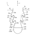
- FIG. 1 is a partially cutaway side view showing a schematic configuration of a gas turbine to which a rotating body according to a first embodiment of the present invention is applied. It is a front view showing a rotating body concerning a 1st embodiment of the present invention. It is a front view which expands and shows the attachment part of the moving blade in the rotary body of FIG.
- FIG. 1 shows an example of a turbomachine to which the rotating body 1 according to the first embodiment of the present invention is applied.
- a gas turbine GT is shown as an example of a turbomachine.
- the gas turbine GT is obtained by compressing the air IA introduced from the outside with the compressor 3 and guiding it to the combustor 5 as compressed air CA, injecting the fuel F into the combustor 5 and combusting it with the compressed air CA.
- the turbine 7 is driven by the high-temperature and high-pressure combustion gas.
- the rotation of the turbine 7 drives a load (not shown) such as a generator connected to the rotor, which is the rotating shaft 9 constituting the rotating body 1.
- a large number of stationary blades 13 planted in the inner peripheral portion of the turbine casing 11 and a large number of moving blades 15 arranged in the outer peripheral portion of the rotor are arranged alternately adjacent to each other in the axial direction. ing. Specifically, as shown in FIG. 2, a large number of rotor blades 15 are planted in the circumferential direction by being connected to the outer peripheral portion of the disk 17 provided on the rotating body 1.
- the rotating body 1 has a rotating shaft 9, a disk 17 protruding in a disk shape on the outer peripheral surface of the rotating shaft 9, and a plurality of moving blades 15 arranged on the outer peripheral portion of the disk 17 in the circumferential direction. ing.
- Each blade 15 has a blade root 21.
- the blade root 21 is a portion arranged on the inner diameter side of the moving blade 15 and fitted and connected to the disk 17.
- the blade root 21 of the moving blade 15 has protrusions 23 for locking the blade root 21 to the disk 17 and protruding to both sides in the direction including the circumferential component.
- the blade root 21 of each rotor blade 15 is formed so that its cross-sectional shape is substantially line-symmetric with respect to the radial direction r of the rotating body 1.
- a “cross section” refers to a cross section based on the rotating body 1.
- the disk 17 has blade grooves 25 on its outer peripheral portion.
- the blade groove 25 has a shape capable of accommodating the blade root 21 of the moving blade 15, and is a portion into which the blade root 21 is fitted.
- the blade groove 25 is formed in a shape capable of accommodating the blade root 21, and has recesses 27 for locking the blade root 21 of the moving blade 15 to the disc 17 which are recessed on both sides in a direction including a circumferential component.
- Have The blade groove 25 of each disk 17 is formed so that its cross-sectional shape is substantially line symmetric with respect to the radial direction r of the rotating body 1.
- a set is called a "dan.”
- the blade root 21 of the moving blade 15 has a plurality of stages (three stages in this example) of protrusions 23.
- the blade groove 25 of the disk 17 also has a plurality of stages (three stages in this example) of recesses 27.
- the blade root 21 and the blade groove 25 have a plurality of stages, they are referred to as the “nth stage” in the order from the radially outer side. That is, the outermost step in the radial direction is the first step.
- each blade root 21 is operated.
- a surface mainly facing the radial outside serves as a contact surface 23a that contacts the surface of the blade groove 25 of the disk 17, and a surface mainly facing the radial inside serves as a non-contact surface 23b.
- a surface mainly facing the inner side in the radial direction serves as a contact surface 27a in contact with the blade root 21, and a surface mainly facing the outer side in the radial direction serves as a non-contact surface 27b.
- the contact surface 23a of the projecting portion 23 of the blade root 21 is inclined so as to extend from the radially inner side toward the radially outer side toward the center of the blade root 21 in a cross-sectional view.
- the contact surface 27a of the recess 27 of the blade groove 25 is also inclined so as to extend from the radially inner side toward the radially outer side toward the central portion of the blade groove 25 in a cross-sectional view.
- the inclination angle extending from the radially outer side to the radially inner side toward the central portion of the blade root 21 or the blade groove 25 is called a "positive" angle, and an angle opposite to the positive angle is called a "negative” angle. That is, the negative angle means an inclination angle extending from the radially inner side to the radially outer side toward the central portion of the blade root 21 or the blade groove 25 (in other words, from the radially inner side to the outer side, the blade root 21 or It is defined as an inclination angle extending toward the center of the blade groove 25).
- the contact surfaces 23a, 27a of the protrusion 23 of the blade root 21 and the recess 27 of the blade groove 25 are inclined at a negative angle.
- the non-contact surface 23b of the projecting portion 23 of at least one step is inclined at a negative angle.
- each non-contact surface 27b of the recess 27 of at least one step is inclined at a negative angle.
- the contact surface 23b is inclined at a negative angle.
- the final stage non-contact surface 23b which is the inner diameter side end 21a of the blade root 21, is formed as a flat surface substantially orthogonal to the radial direction r.
- the non-contact surfaces 27b of the recesses 27 of all the stages (the first stage and the second stage in this example) of the blade groove 25 except the final stage (the third stage in this example) are inclined at a negative angle. ing.
- the final stage non-contact surface 27b which is the inner diameter side end portion 25a of the blade groove 25, is formed as a curved surface that is recessed inward in the radial direction as a whole.
- the shape of the recesses 27 of all the stages (the first stage and the second stage in this example) except the final stage (the third stage in this example) is the blade root of the moving blade 15. Since it is formed in a shape substantially corresponding to the shape of the protruding portion 23 of the corresponding step of 21, the description of the shape of the concave portion 27 of the blade groove 25 may be omitted in the following description.
- the non-contact surfaces 23b and 27b of the protrusion 23 of the blade root 21 and the recess 27 of the blade groove 25 are formed so as to be inclined at a negative angle. It is possible to suppress local stress concentration from occurring in the blade 21 and the blade groove 25. This action will be described in detail below.
- FIG. 9 shows the shapes of the blade root 21 of the rotor blade 15 and the blade groove 25 of the disk 17 of the rotary body 101 according to a general conventional example.
- the respective non-contact surfaces 23b and 27b are inclined at a positive angle.
- the blade root 21 and the blade groove 25 according to such a conventional example (1) both ends of the contact portion on the contact surface (hereinafter, simply referred to as “contact end portion”) 31, 31 and (2) blade root.
- a large stress concentration occurs in the arc-shaped concave portions (hereinafter, simply referred to as “R-shaped portions”) 33 of the blade 21 and the blade groove 25 adjacent to the contact end portion 31.
- the blade root 21 and the blade groove 25 by changing the shape of the blade root 21 and the blade groove 25 by inclining the non-contact surface at a negative angle, the blade root 21 and the blade groove 25 can be changed in shape. This can be realized without increasing the radial dimension and the circumferential dimension of the root 21 and the blade groove 25.
- the contact surface 23a of the protrusion 23 of the blade root 21 and the non-contact surface 23b are inclined at a negative angle, so that The cross-sectional shape of the protruding portion 23 is elongated as compared with the shape. That is, the width dimension of the protrusion 23 is thin and uniform over the entire protrusion 23. The same applies to the protruding portion between the concave portions 27 of the blade groove 25. With such a shape, the center of gravity of the rigidity distribution of both protrusions is shifted to the tip side as compared with the conventional shape, and the stress concentration at the contact end portion 31 is relaxed.
- the projecting portion 23 has a slender cross-sectional shape, it is easy to increase the radius of curvature of the non-contact portion adjacent to the contact end portion 31.
- the R-shaped portion 33 on the root side of the contact end portion 31 of the protruding portion 23 is formed in a curved shape having two different radiuses of curvature.
- the R-shaped portion 33 adjacent to the contact end portion 31 is referred to as a “first R-shaped portion 33A”
- the R-shaped portion 33 that is adjacent to the first R-shaped portion 33A and forms the tip portion of the protruding portion 23 is referred to as a “first R-shaped portion 33A”.
- 2R-shaped portion 33B is referred to as a “first R-shaped portion 33A”.
- the R-shaped portion 33 adjacent to the contact end portion 31 is also formed in a curved shape having two different radii of curvature.
- the radius of curvature of the first R-shaped portion 33A in the present embodiment is set to about 3 times the radius of curvature of the first R-shaped portion in the conventional R-shaped portion.
- FIG. 5 and FIG. 6 show the calculation results of simulating the stress concentration state for the shape according to the present embodiment (shape of FIG. 3: Example) and conventional shape (shape of FIG. 9: comparative example).
- FIG. 5 shows the result of calculation of the minimum principal stress, that is, the magnitude of the maximum compressive stress at the location of the example and the comparative example.
- FIG. 6 shows the results of calculation of the maximum principal stress, that is, the magnitude of the maximum tensile stress at the location of the example and the comparative example.
- the length of the contact portion between the blade root and the blade groove was the same in the example and the comparative example.
- the first-stage and second-stage protruding portions 23 of the blade root 21 are further formed in a tapered cross-sectional shape. That is, in each of the protrusions 23 shown in FIG. 4, the inclination angle ⁇ 2 of the non-contact surface 23b with respect to the radial direction r is larger than the inclination angle ⁇ 1 of the contact surface 23a with respect to the radial direction r. Similarly, the concave portions 27 of the first and second stages of the blade groove 25 are formed in a tapered cross-sectional shape.
- the inclination angle ⁇ 2 of the non-contact surface 27b with respect to the radial direction r is larger than the inclination angle ⁇ 1 of the contact surface 27a with respect to the radial direction r.
- the inclination angle ⁇ 1 of the contact surface refers to the inclination angle of the contact surfaces 31 and 31 with respect to the radial direction r at the midpoint M1 of the contact ends 31, 31, and the inclination angle ⁇ 2 of the non-contact surface corresponds to the rotating body 1.
- the inclination angle of the straight line is the “inclination angle ⁇ 1” or the “inclination angle ⁇ 2”.
- the inclination angle at the intermediate point is the “inclination angle ⁇ 1” or the “inclination angle ⁇ 2”.
- the non-contact surface 27b of the inner diameter side end portion 25a (recessed portion 27 at the final stage) of the blade groove 25 of the disk 17 further has a cross-sectional shape of the blade of the moving blade 15.
- the root 21 has a larger radius of curvature than the non-contact surface 23b of the inner diameter side end 21a (final stage protrusion 23).
- the radius of curvature of the non-contact surface 27b of the inner diameter side end portion 25a of the blade groove 25 is preferably as large as possible within a range capable of supporting the entire size of the disk 17 and sufficiently securing the moving blade 15 supporting performance.
- the concave portion 27 of the inner diameter side end portion 25a of the blade groove 25 also has a large radius of curvature, so that stress concentration in this portion can be relaxed.
- the contact end portion is formed.
- the stress concentration in 31 and R-shaped portion 33 can be relaxed without increasing the overall dimensions of blade root 21 and blade groove 25.
- FIG. 7 shows a rotating body 1 according to the second embodiment of the present invention.
- an inner diameter end recess 41 that is recessed radially outward is formed in the final stage non-contact surface 23b that is the inner diameter side end 21a of the blade root 21 of the rotor blade 15.
- Other configurations of this embodiment are the same as those of the first embodiment shown in FIG.
- the inner diameter end recess 41 in the inner diameter side end portion 21a of the blade root 21 of the moving blade 15 the thickness of the portion that hardly contributes to the support of the moving blade 15 is reduced and the weight of the moving blade 15 is reduced. It can be reduced. As a result, the centrifugal force applied to the moving blade 15 is reduced, and as a result, the stress generated in the entire blade root 21 and blade groove 25 is also reduced. Furthermore, by forming the inner diameter end concave portion 41 in the inner diameter side end portion 21a corresponding to the final stage protruding portion 23 of the blade root 21, the non-contact surfaces 23b and 27b in the final stage protruding portion 23 also have a negative angle. Will be inclined at. As a result, the center of gravity of the rigidity distribution shifts toward the tip end side in the projecting portion 23 at the final stage, so that stress concentration at the contact end portion 31 is relieved.
- the blade root 21 of the moving blade 15 may have the protrusion 23 having only one step, and the blade groove 25 of the disk 17 may have the recess 27 having only one step.
- the non-contact surface 23b of the only projecting portion 23 that is the inner diameter side end 21a of the blade root 21 is inclined at a negative angle, so that the inner diameter end recess 41 is formed in the inner diameter side end 21a. become.
- the rotor blades 15 of the rotating body 1 according to the present invention, the disk 17, and the rotating body 1 including these are not only the turbine of the gas turbine shown as an example in each of the above-described embodiments, but also, for example, a compressor of the gas turbine, It can be applied to various turbomachines such as a steam turbine.
Landscapes
- Engineering & Computer Science (AREA)
- Mechanical Engineering (AREA)
- General Engineering & Computer Science (AREA)
- Turbine Rotor Nozzle Sealing (AREA)
- Structures Of Non-Positive Displacement Pumps (AREA)
Abstract
Description
当該動翼の翼根が、横断面形状において、
当該翼根をディスクに係止するための、周方向成分を含む方向の両側に突出する突出部を少なくとも1段有し、
前記突出部の、ディスクに接触する接触面が、当該翼根の中央部に向かうに従って径方向内側から径方向外側に延びるように傾斜しており、
前記突出部の、ディスクに接触しない非接触面が、当該翼根の中央部に向かうに従って径方向内側から径方向外側に延びるように傾斜している。
当該ディスクの翼溝が、横断面形状において、
動翼の翼根を当該ディスクに係止するための、周方向成分を含む方向の両側に凹む凹部を少なくとも1段有し、
前記凹部の、翼根に接触する接触面が、当該翼溝の中央部に向かうに従って径方向内側から径方向外側に延びるように傾斜しており、
前記凹部の、翼根に接触しない非接触面が、当該翼溝の中央部に向かうに従って径方向内側から径方向外側に延びるように傾斜している。
前記したいずれかの動翼と、
前記動翼の翼根を収容可能な形状の翼溝を有する、前記したいずれかのディスクと、
を備えている。
15 動翼
17 ディスク
21 翼根
23 突出部
25 翼溝
27 凹部
Claims (9)
- 回転体のディスクに植設される動翼であって、
当該動翼の翼根が、横断面形状において、
当該翼根をディスクに係止するための、周方向成分を含む方向の両側に突出する突出部を少なくとも1段有し、
前記突出部の、ディスクに接触する接触面が、当該翼根の中央部に向かうに従って径方向内側から径方向外側に延びるように傾斜しており、
前記突出部の、ディスクに接触しない非接触面が、当該翼根の中央部に向かうに従って径方向内側から径方向外側に延びるように傾斜している、
動翼。 - 請求項1に記載の動翼において、前記翼根の前記突出部が、先細りの横断面形状を有している動翼。
- 請求項1または2に記載の動翼において、複数段の前記突出部を有する動翼。
- 請求項3に記載の動翼において、前記翼根の内径側端部に、径方向外側に凹む内径端凹部が形成されている動翼。
- 動翼が植設される回転体のディスクであって、
当該ディスクの翼溝が、横断面形状において、
動翼の翼根を当該ディスクに係止するための、周方向成分を含む方向の両側に凹む凹部を少なくとも1段有し、
前記凹部の、翼根に接触する接触面が、当該翼溝の中央部に向かうに従って径方向内側から径方向外側に延びるように傾斜しており、
前記凹部の、翼根に接触しない非接触面が、当該翼溝の中央部に向かうに従って径方向内側から径方向外側に延びるように傾斜している、
ディスク。 - 請求項5に記載のディスクにおいて、前記翼溝の前記凹部が、先細りの横断面形状を有しているディスク。
- 請求項5または6に記載のディスクにおいて、複数段の前記凹部を有するディスク。
- 複数の動翼が植設された回転体であって、
請求項1から4のいずれか一項に記載の動翼と、
前記動翼の翼根を収容可能な形状の翼溝を有する、請求項5から7のいずれか一項に記載のディスクと、
を備える回転体。 - 請求項8に記載の回転体において、前記翼溝の内径側端部の、前記翼根に接触しない非接触面が、横断面形状において、前記翼根の内径側端部の非接触面よりも大きい曲率半径を有する回転体。
Priority Applications (4)
| Application Number | Priority Date | Filing Date | Title |
|---|---|---|---|
| DE112019006421.5T DE112019006421B4 (de) | 2018-12-28 | 2019-12-13 | Rotorschaufel, scheibe und rotationskörper |
| CN201980085482.6A CN113227540A (zh) | 2018-12-28 | 2019-12-13 | 旋转体的动翼以及轮盘 |
| GB2109949.4A GB2594847B (en) | 2018-12-28 | 2019-12-13 | Rotor blade and disc of rotating body |
| US17/358,877 US11946390B2 (en) | 2018-12-28 | 2021-06-25 | Rotor blade and disc of rotating body |
Applications Claiming Priority (2)
| Application Number | Priority Date | Filing Date | Title |
|---|---|---|---|
| JP2018-248016 | 2018-12-28 | ||
| JP2018248016A JP7385992B2 (ja) | 2018-12-28 | 2018-12-28 | 回転体の動翼およびディスク |
Related Child Applications (1)
| Application Number | Title | Priority Date | Filing Date |
|---|---|---|---|
| US17/358,877 Continuation US11946390B2 (en) | 2018-12-28 | 2021-06-25 | Rotor blade and disc of rotating body |
Publications (1)
| Publication Number | Publication Date |
|---|---|
| WO2020137599A1 true WO2020137599A1 (ja) | 2020-07-02 |
Family
ID=71129071
Family Applications (1)
| Application Number | Title | Priority Date | Filing Date |
|---|---|---|---|
| PCT/JP2019/048856 Ceased WO2020137599A1 (ja) | 2018-12-28 | 2019-12-13 | 回転体の動翼およびディスク |
Country Status (6)
| Country | Link |
|---|---|
| US (1) | US11946390B2 (ja) |
| JP (1) | JP7385992B2 (ja) |
| CN (1) | CN113227540A (ja) |
| DE (1) | DE112019006421B4 (ja) |
| GB (1) | GB2594847B (ja) |
| WO (1) | WO2020137599A1 (ja) |
Families Citing this family (2)
| Publication number | Priority date | Publication date | Assignee | Title |
|---|---|---|---|---|
| US12366171B2 (en) * | 2023-05-26 | 2025-07-22 | General Electric Company | Fan assemblies with fan disk inserts and methods of assembling the same |
| CN117001369B (zh) * | 2023-09-18 | 2024-01-02 | 广州德力数控设备有限公司 | 一种大行程的螺旋桨负角度加工动柱机 |
Citations (8)
| Publication number | Priority date | Publication date | Assignee | Title |
|---|---|---|---|---|
| US5310317A (en) * | 1992-08-11 | 1994-05-10 | General Electric Company | Quadra-tang dovetail blade |
| JP2000512707A (ja) * | 1996-06-21 | 2000-09-26 | シーメンス アクチエンゲゼルシヤフト | 溝内に装着可能な翼を有するタービン機械のロータ及びロータの翼 |
| JP2000337294A (ja) * | 1999-04-30 | 2000-12-05 | General Electric Co <Ge> | 応力除去された動翼支持構造 |
| US20030129060A1 (en) * | 2001-10-13 | 2003-07-10 | Knott David S. | Indentor arrangement |
| JP2003314207A (ja) * | 2002-04-16 | 2003-11-06 | United Technol Corp <Utc> | ブレード付きロータおよびスペーサ |
| US20080232972A1 (en) * | 2007-03-23 | 2008-09-25 | Richard Bouchard | Blade fixing for a blade in a gas turbine engine |
| JP2008540921A (ja) * | 2005-05-12 | 2008-11-20 | ゼネラル・エレクトリック・カンパニイ | 動翼/ディスク(7FA+e、第2段)の応力を低減するための動翼/ディスクダブテールバックカット |
| US20140140852A1 (en) * | 2011-07-14 | 2014-05-22 | Richard Bluck | Blade root, corresponding blade, rotor disc, and turbomachine assembly |
Family Cites Families (8)
| Publication number | Priority date | Publication date | Assignee | Title |
|---|---|---|---|---|
| DE4435268A1 (de) * | 1994-10-01 | 1996-04-04 | Abb Management Ag | Beschaufelter Rotor einer Turbomaschine |
| JP2005220825A (ja) * | 2004-02-06 | 2005-08-18 | Mitsubishi Heavy Ind Ltd | タービン動翼 |
| US8606516B2 (en) * | 2004-11-30 | 2013-12-10 | Dash Navigation, Inc. | User interface system and method for a vehicle navigation device |
| US7191019B2 (en) * | 2005-06-02 | 2007-03-13 | Markem Corporation | Dynamic line configuration |
| JP2008088832A (ja) | 2006-09-29 | 2008-04-17 | Hitachi Ltd | タービンロータ |
| EP2808490A1 (en) * | 2013-05-29 | 2014-12-03 | Alstom Technology Ltd | Turbine blade with locking pin |
| WO2017033226A1 (ja) | 2015-08-21 | 2017-03-02 | 三菱重工コンプレッサ株式会社 | 蒸気タービン |
| JP6785555B2 (ja) | 2016-01-15 | 2020-11-18 | 三菱パワー株式会社 | 動翼のタービンロータへの組付方法 |
-
2018
- 2018-12-28 JP JP2018248016A patent/JP7385992B2/ja active Active
-
2019
- 2019-12-13 DE DE112019006421.5T patent/DE112019006421B4/de active Active
- 2019-12-13 WO PCT/JP2019/048856 patent/WO2020137599A1/ja not_active Ceased
- 2019-12-13 CN CN201980085482.6A patent/CN113227540A/zh active Pending
- 2019-12-13 GB GB2109949.4A patent/GB2594847B/en active Active
-
2021
- 2021-06-25 US US17/358,877 patent/US11946390B2/en active Active
Patent Citations (8)
| Publication number | Priority date | Publication date | Assignee | Title |
|---|---|---|---|---|
| US5310317A (en) * | 1992-08-11 | 1994-05-10 | General Electric Company | Quadra-tang dovetail blade |
| JP2000512707A (ja) * | 1996-06-21 | 2000-09-26 | シーメンス アクチエンゲゼルシヤフト | 溝内に装着可能な翼を有するタービン機械のロータ及びロータの翼 |
| JP2000337294A (ja) * | 1999-04-30 | 2000-12-05 | General Electric Co <Ge> | 応力除去された動翼支持構造 |
| US20030129060A1 (en) * | 2001-10-13 | 2003-07-10 | Knott David S. | Indentor arrangement |
| JP2003314207A (ja) * | 2002-04-16 | 2003-11-06 | United Technol Corp <Utc> | ブレード付きロータおよびスペーサ |
| JP2008540921A (ja) * | 2005-05-12 | 2008-11-20 | ゼネラル・エレクトリック・カンパニイ | 動翼/ディスク(7FA+e、第2段)の応力を低減するための動翼/ディスクダブテールバックカット |
| US20080232972A1 (en) * | 2007-03-23 | 2008-09-25 | Richard Bouchard | Blade fixing for a blade in a gas turbine engine |
| US20140140852A1 (en) * | 2011-07-14 | 2014-05-22 | Richard Bluck | Blade root, corresponding blade, rotor disc, and turbomachine assembly |
Also Published As
| Publication number | Publication date |
|---|---|
| US11946390B2 (en) | 2024-04-02 |
| DE112019006421T5 (de) | 2021-09-23 |
| JP7385992B2 (ja) | 2023-11-24 |
| GB202109949D0 (en) | 2021-08-25 |
| GB2594847A (en) | 2021-11-10 |
| DE112019006421B4 (de) | 2026-04-23 |
| JP2020106015A (ja) | 2020-07-09 |
| US20210324750A1 (en) | 2021-10-21 |
| CN113227540A (zh) | 2021-08-06 |
| GB2594847B (en) | 2023-05-31 |
Similar Documents
| Publication | Publication Date | Title |
|---|---|---|
| CN102656339B (zh) | 一种具有受控加载的涡轮机叶片阻尼装置的涡轮机转子 | |
| US9822647B2 (en) | High chord bucket with dual part span shrouds and curved dovetail | |
| JP5681384B2 (ja) | タービンエンジン用のロータブレード | |
| JP6408888B2 (ja) | タービンバケット閉鎖組立体及びその組立方法 | |
| KR20040097938A (ko) | 터빈 휠용 버킷의 조립체 | |
| US20100166562A1 (en) | Turbine blade root configurations | |
| EP2878771B1 (en) | Axial flow fluid machine | |
| CN102575524A (zh) | 配备有相对于盘锁定叶片的轴向保持环的涡轮机叶轮 | |
| US10738640B2 (en) | Shroud, blade member, and rotary machine | |
| US20160108737A1 (en) | Blade system, and corresponding method of manufacturing a blade system | |
| US11946390B2 (en) | Rotor blade and disc of rotating body | |
| US6155788A (en) | Rotor assembly | |
| US9004872B2 (en) | Bearing surface combined load-lock slots for tangential rotors | |
| JP2017519143A (ja) | タービンエンジンロータ用の回転対称部品、ならびに関連するタービンエンジンロータ、タービンエンジンモジュール、およびタービンエンジン | |
| JP2011137454A (ja) | タービンエンジンロータブレード及びロータホイール | |
| US20180283188A1 (en) | Rotating unit and steam turbine including the same | |
| US20210246801A1 (en) | Turbine Wheel | |
| US20080050238A1 (en) | Disc firtree slot with truncation for blade attachment | |
| KR20100019348A (ko) | 터빈 동익과 그 고정 구조 | |
| WO2017184138A1 (en) | Preloaded snubber assembly for turbine blades | |
| US9422820B2 (en) | Method and system for self-locking a closure bucket in a rotary machine | |
| JP4182098B2 (ja) | ガスタービンのケーシング | |
| US9441639B2 (en) | Compressor rotor heat shield | |
| CN115552124B (zh) | 涡轮机的具有控制轴向接合处相对增长的特征的转子结构 | |
| WO2019107132A1 (ja) | インペラ、回転機械 |
Legal Events
| Date | Code | Title | Description |
|---|---|---|---|
| 121 | Ep: the epo has been informed by wipo that ep was designated in this application |
Ref document number: 19902609 Country of ref document: EP Kind code of ref document: A1 |
|
| WWE | Wipo information: entry into national phase |
Ref document number: 112019006421 Country of ref document: DE |
|
| ENP | Entry into the national phase |
Ref document number: 202109949 Country of ref document: GB Kind code of ref document: A Free format text: PCT FILING DATE = 20191213 |
|
| WWE | Wipo information: entry into national phase |
Ref document number: 2109949.4 Country of ref document: GB |
|
| 122 | Ep: pct application non-entry in european phase |
Ref document number: 19902609 Country of ref document: EP Kind code of ref document: A1 |
|
| WWG | Wipo information: grant in national office |
Ref document number: 2109949.4 Country of ref document: GB |
|
| WWG | Wipo information: grant in national office |
Ref document number: 112019006421 Country of ref document: DE |