WO2020137526A1 - 画像検査器生成装置、画像検査装置、画像検査器生成プログラム、及び画像検査器生成方法 - Google Patents
画像検査器生成装置、画像検査装置、画像検査器生成プログラム、及び画像検査器生成方法 Download PDFInfo
- Publication number
- WO2020137526A1 WO2020137526A1 PCT/JP2019/048327 JP2019048327W WO2020137526A1 WO 2020137526 A1 WO2020137526 A1 WO 2020137526A1 JP 2019048327 W JP2019048327 W JP 2019048327W WO 2020137526 A1 WO2020137526 A1 WO 2020137526A1
- Authority
- WO
- WIPO (PCT)
- Prior art keywords
- image
- inspection
- classifier
- inspection device
- learning
- Prior art date
- Legal status (The legal status is an assumption and is not a legal conclusion. Google has not performed a legal analysis and makes no representation as to the accuracy of the status listed.)
- Ceased
Links
Images

Classifications
-
- G—PHYSICS
- G06—COMPUTING OR CALCULATING; COUNTING
- G06N—COMPUTING ARRANGEMENTS BASED ON SPECIFIC COMPUTATIONAL MODELS
- G06N3/00—Computing arrangements based on biological models
- G06N3/02—Neural networks
- G06N3/08—Learning methods
- G06N3/09—Supervised learning
-
- G—PHYSICS
- G06—COMPUTING OR CALCULATING; COUNTING
- G06N—COMPUTING ARRANGEMENTS BASED ON SPECIFIC COMPUTATIONAL MODELS
- G06N3/00—Computing arrangements based on biological models
- G06N3/02—Neural networks
- G06N3/04—Architecture, e.g. interconnection topology
-
- G—PHYSICS
- G06—COMPUTING OR CALCULATING; COUNTING
- G06N—COMPUTING ARRANGEMENTS BASED ON SPECIFIC COMPUTATIONAL MODELS
- G06N3/00—Computing arrangements based on biological models
- G06N3/02—Neural networks
- G06N3/04—Architecture, e.g. interconnection topology
- G06N3/0464—Convolutional networks [CNN, ConvNet]
-
- G—PHYSICS
- G06—COMPUTING OR CALCULATING; COUNTING
- G06N—COMPUTING ARRANGEMENTS BASED ON SPECIFIC COMPUTATIONAL MODELS
- G06N3/00—Computing arrangements based on biological models
- G06N3/02—Neural networks
- G06N3/08—Learning methods
- G06N3/096—Transfer learning
-
- G—PHYSICS
- G06—COMPUTING OR CALCULATING; COUNTING
- G06T—IMAGE DATA PROCESSING OR GENERATION, IN GENERAL
- G06T7/00—Image analysis
Definitions
- the present invention relates to an image inspection device generation device, an image inspection device, an image inspection device generation program, and an image inspection device generation method.
- a CNN generation unit that generates a CNN (Convolutional Neural Network) by deep learning based on first teacher data that includes a plurality of first images showing defects
- a CNN generation unit By a feature amount acquisition unit that inputs each of a plurality of second images in which defects are captured and acquires a plurality of types of feature amounts for each of the plurality of second images, and a feature amount acquisition unit.
- a classifier generating unit that generates a classifier by machine learning based on the second teacher data including at least a part of the acquired characteristic amounts of a plurality of kinds of characteristic amounts is known (Patent Reference 1).
- Patent Document 1 describes that a classifier generated by the classifier generation device classifies an image of an inspection target, in which an image of a defect appears.
- the present invention provides an image inspection device generation apparatus, an image inspection device generation program, and an image inspection device generation method capable of generating an image inspection device with high inspection accuracy without requiring a large amount of images. With the goal.
- An image inspector generator is an image inspector generator that generates an image inspector for inspecting an inspection object included in an image by machine learning based on an inspection standard for an inspection object and a learning image.
- the inspection criterion includes the state variable of the inspection object, the state value of the state variable, and information of the class into which the inspection object is classified.
- the image inspection device for inspecting the inspection object included in the image is generated by the machine learning based on the inspection reference for the inspection object and the learning image, and the inspection reference is the state variable of the inspection object, the state. It contains the state value of the variable and information about the class into which the inspection object is classified.
- the inspection reference is the state variable of the inspection object, the state. It contains the state value of the variable and information about the class into which the inspection object is classified.
- the image inspector includes a detector and a classifier, and the image inspector generation unit detects a detector in the image and a detector generation unit that generates a detector that detects an inspection object included in the image. And a classifier generator that generates a classifier that classifies the states of the inspection objects.
- the detector that detects the inspection object included in the image is generated, and the classifier that classifies the state of the inspection object detected in the image is generated.
- the inspection object can be generated by machine learning. While the learning images of different variations having different states are unnecessary, the generation of the classifier by machine learning does not require learning images of different variations such as the number, position, and range of inspection objects.
- the classifier generation unit may generate the classifier by machine learning based on the partial image of the inspection object detected in the image.
- the classifier is generated by machine learning based on the partial image of the inspection object detected in the image.
- the number, position, range, etc. of the inspection objects in the learning image are removed. Therefore, by generating a classifier by machine learning based on partial images of variations with different inspection object states, a large amount of learning images can be obtained. It is possible to easily realize a classifier generation unit that generates a classifier without requiring.
- an input unit for inputting the inspection standard may be further provided.
- an input unit for inputting the inspection standard is further provided.
- the inspection standard can be easily set.
- An image inspection apparatus includes an image inspection device generated by the image inspection device generation device described above, and inspects an inspection image using the image inspection device.
- the image inspector is generated by machine learning based on a plurality of inspection standards, and when the inspection image is determined to be defective as a result of inspection using the image inspector, a plurality of inspection standards Of these, an output unit that outputs the inspection standard that causes the determination that there is a defect may be further provided.
- the inspection standard that causes the defect to be determined is output from the plurality of inspection standards. To be done.
- the inspection result using the image inspection device is more descriptive than in the case where the inspection reference that causes the defect is not output.
- An image inspection device generation program is an image inspection device generation program executed by a computer, and is included in an image by machine learning based on an inspection standard for an inspection object and a learning image.
- the method includes an image inspector generating step of generating an image inspector for inspecting an inspection object, and the inspection standard includes a state variable of the inspection object, a state value of the state variable, and information of a class into which the inspection object is classified.
- the image inspection device for inspecting the inspection object included in the image is generated by the machine learning based on the inspection reference for the inspection object and the learning image, and the inspection reference is the state variable of the inspection object and the state. It contains the state value of the variable and information about the class into which the inspection object is classified.
- the inspection reference is the state variable of the inspection object and the state. It contains the state value of the variable and information about the class into which the inspection object is classified.
- the image inspector includes a detector and a classifier
- the image inspector generating step includes a detector generating step for generating a detector for detecting an inspection object included in the image, and the image inspecting step for detecting in the image. Generating a classifier that classifies the states of the inspection objects described above.
- the detector that detects the inspection object included in the image is generated, and the classifier that classifies the state of the inspection object detected in the image is generated.
- the inspection object can be generated by machine learning. While the learning images of different variations having different states are unnecessary, the generation of the classifier by machine learning does not require learning images of different variations such as the number, position, and range of inspection objects.
- the classifier generating step may include generating a classifier by machine learning based on the partial image of the inspection object detected in the image.
- the classifier is generated by machine learning based on the partial image of the inspection object detected in the image.
- the number, position, range, etc. of the inspection objects in the learning image are removed. Therefore, by generating a classifier by machine learning based on partial images of variations with different inspection object states, a large amount of learning images can be obtained.
- the classifier generating step for generating the classifier can be easily realized without requiring
- an input step for inputting the inspection standard may be further included.
- An image inspection device generating method is an image inspection device that generates an image inspection device that inspects an inspection object included in an image by machine learning based on an inspection standard for the inspection object and a learning image.
- the inspection standard includes a state variable of the inspection object, a state value of the state variable, and information of a class into which the inspection object is classified.
- the image inspection device for inspecting the inspection object included in the image is generated by the machine learning based on the inspection reference for the inspection object and the learning image, and the inspection reference is the state variable of the inspection object, the state. It contains the state value of the variable and information about the class into which the inspection object is classified.
- the inspection reference is the state variable of the inspection object, the state. It contains the state value of the variable and information about the class into which the inspection object is classified.
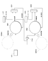
- FIG. 1 is a configuration diagram illustrating a schematic configuration of an image inspection system according to an embodiment.
- FIG. 2 is a diagram illustrating a schematic configuration for generating the image inspection device shown in FIG. 1.
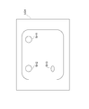
- FIG. 3 is a diagram illustrating a first example of generation of an image inspection device by machine learning.
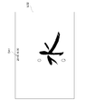
- FIG. 4 is a diagram illustrating a second embodiment of generation of an image inspection device by machine learning.
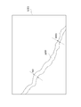
- FIG. 5 is a diagram illustrating a third example of generation of the image inspection device 33 by machine learning.
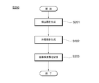
- FIG. 6 is a flowchart showing a schematic operation of generating an image inspection device of the image inspection device generation device according to the embodiment.
- FIG. 1 is a configuration diagram illustrating a schematic configuration of an image inspection system 100 according to an embodiment.
- FIG. 2 is a diagram exemplifying a schematic configuration for generating the image inspection device 33 shown in FIG.
- FIG. 3 is a diagram illustrating a first example of generation of the image inspection device 33 by machine learning.
- FIG. 4 is a diagram illustrating a second example of generation of the image inspection device 33 by machine learning.
- FIG. 5 is a diagram illustrating a third example of generation of the image inspection device 33 by machine learning.
- the image inspection system 100 includes a network NW, an image inspection device generation device 50, and an image inspection device 90.
- the image inspection device generation device 50 and the image inspection device 90 are communicably connected to each other via the network NW.
- the network NW is, for example, the Internet, LAN (Local Area Network), leased line, telephone line, corporate network, Bluetooth (registered trademark), Wi-Fi (Wireless Fidelity), mobile communication network, other communication lines, or These are combinations and the like. Further, the connection between the image inspection device generation device 50 and the image inspection device 90 and the network NW does not matter whether they are wired or wireless.
- the image inspection system 100 includes one network NW is shown in FIG. 1, but the present invention is not limited to this.
- the number of networks included in the image inspection system 100 may be two or more, for example.
- the image inspection device generation device 50 is a computer that functions as a host controller of the image inspection device 90.
- the image inspection device generation apparatus 50 is configured to include a controller such as a PLC (Programmable Logic Controller), for example.
- a controller such as a PLC (Programmable Logic Controller), for example.
- the image inspection device generation device 50 includes, for example, a communication unit 10, an input unit 20, a storage unit 30, and a control unit 40.
- the image inspector generation device 50 further includes a bus 51 configured to transmit signals and data between the respective units of the image inspector generation device 50.
- the communication unit 10 is configured to communicate (transmit and receive) data via the network NW. More specifically, the communication unit 10 is configured to be able to communicate with the image inspection device 90 connected to the network NW via the network NW based on one or a plurality of predetermined communication methods.
- the input unit 20 is for inputting an inspection standard 32 described later. More specifically, the input unit 20 is configured so that an inspection standard can be input to the image inspection device generation apparatus 50 by a user (user) operation.
- the input unit 20 is configured to include, for example, an interface and an input device that is an external device.
- the interface is configured to exchange data and signals with an external device, and is standardized such as USB (Universal Serial Bus), HDMI (registered trademark) (High-Definition Mutimedia Interface), and IEEE 1394. Includes interface connection terminals.
- the input device is, for example, a device such as a keyboard, a keypad, a mouse, a trackball, a touch panel, and a microphone.
- the input unit 20 when a user operates an input device such as a keyboard, a keypad, a mouse, a trackball, a touch panel, and a microphone (including a voice operation using a microphone), the input unit 20 causes the data corresponding to the operation. Alternatively, a signal is output. The data or signal output by the input unit 20 is input to the control unit 40. The control unit 40 generates the inspection standard 32 based on this data or signal, so that it becomes possible to input the inspection standard to the image inspection device generation device 50. In this way, by providing the input unit 20 for inputting the inspection standard 32, the inspection standard 32 can be easily set.
- an input device such as a keyboard, a keypad, a mouse, a trackball, a touch panel, and a microphone (including a voice operation using a microphone)
- the input unit 20 causes the data corresponding to the operation.
- a signal is output.
- the data or signal output by the input unit 20 is input to the control unit 40.
- the control unit 40 generates the inspection
- the storage unit 30 is configured to store programs and data.
- the storage unit 30 includes, for example, a hard disk drive, a solid state drive, and the like.
- the storage unit 30 stores various programs executed by the control unit 40, data necessary for executing the programs, and the like in advance.
- the storage unit 30 also stores learning data 31, a plurality of inspection standards 32, and a plurality of image inspection devices 33.
- the learning data 31 includes a plurality of learning images and teacher data given to the corresponding learning images.
- Each inspection criterion 32 is for an inspection object included in the image.
- One or more inspection standards 32 are set for each inspection object.
- the control unit 40 is configured to control the operations of the communication unit 10, the input unit 20, the storage unit 30, and the like of the image inspection device generating apparatus 50. Further, the control unit 40 is configured to realize each function described below by executing a program stored in the storage unit 30 or the like.
- the control unit 40 is configured to include a processor such as a CPU (Central Processing Unit), a memory such as a ROM (Read Only Memory), a RAM (Random Access Memory), and a buffer storage device such as a buffer.
- control unit 40 includes, for example, an image inspection device generation unit 45 as its functional configuration.
- the image inspector generation unit 45 generates the image inspector 33 that inspects the inspection object included in the image by machine learning based on the inspection reference 32 for the inspection object and the learning image included in the learning data 31. It is configured. More specifically, the image inspector 33 includes a detector 33a and a classifier 33b, and the image inspector generator 45 includes a detector generator 41 and a classifier generator 42.
- the detector generation unit 41 is configured to generate a detector 33a that detects the inspection object included in the image by machine learning based on the inspection standard 32 and the learning image included in the learning data 31.
- the classifier generation unit 42 generates the classifier 33b that classifies the state of the inspection object detected in the inspection image by machine learning based on the inspection standard 32 and the learning image included in the learning data 31. It is configured.
- the image inspection device 33 including the detector 33a and the classifier 33b is generated.
- the control unit 40 generates the image inspection device 33 for each inspection object, and the generated image inspection device 33 is stored in the storage unit 30.
- the control unit 40 When the information of the inspection standard is input by the operation of the user (user), the control unit 40 generates the inspection standard 32 for the inspection object.
- the generated inspection standard 32 is stored in the storage unit 30.
- the inspection standard 32 is described in a format such as “NG if the state variable X of the inspection object A is the state value X1” or “NG if the state variable Y of the inspection object B is the state value Y1”.
- the inspection standard 32 is not limited to one for each inspection object, and a plurality of inspection standards 32 may be input and set.
- the inspection standard 32 includes “inspection object”, “state variable”, “state value” of the state variable, and information of the class into which the image is classified.
- the control unit 40 uses the information of the “inspection object”, the “state variable”, and the “state value” of the state variable input by the user (user) to classify the inspection object into the “OK” class and “NG”.
- the inspection standard 32 for classifying into one of the “NG” classes out of the two classes may be generated.
- the learning efficiency of the machine learning is improved by performing the machine learning based on the inspection reference 32 which is the logical information and the learning image, as compared with the case where the machine learning is performed based on the learning image. It will be possible. Therefore, as compared with the related art, it is possible to generate the image inspection device 33 with high inspection accuracy without requiring a large amount of learning images.
- the inspection object is a part of the object shown in the image.
- the inspection object is, for example, a screw hole, a cable, a needle, a container, a ring, an electrode, a cutting surface, or a expiration date printout.
- State variables are variables of the inspection object.
- the state variables are, for example, width, length, area, size, direction, number, color, shape, surface state, date and the like.
- State value is the value of the relevant state variable.
- the state value is, for example, 100 pixels, parallel, 30 degrees, four, red, variable, burr, scratch, stain, cloudy, October 17, and the like.
- the detector 33a and the classifier 33b are generated using an algorithm of an arbitrary machine learning model.
- the detector 33a is generated using, for example, the first neural network NN1 shown in FIG. 2, and the classifier 33b is generated using, for example, the second neural network NN2 shown in FIG.
- the first neural network NN1 is a neural network for detecting an inspection object included in the learning image, for example, “inspection object A”.
- the first neural network NN1 is obtained by transfer learning of the object recognition neural network ORNN generated by learning in advance.
- the object recognition neural network ORNN is learned to detect a general object including the “inspection object A” by using an object detection algorithm such as SSD (Single Shot multibox Detector).
- the transfer learning is performed by inputting the learning image LG included in the learning data 31 to the first neural network NN1 and learning so that the first neural network NN1 detects the “inspection object A”.
- the detection result of the first neural network NN1 is input to the first determiner DD1.
- the first determiner DD1 compares the detection result of the first neural network NN1 with the first teacher data LD1 included in the learning data 31 and corresponding to the learning image LG, and determines whether or not they match.
- the first teacher data LD1 is an annotation attached to the learning image LG, that is, related information. In the example shown in FIG. 2, the label “OK” or “NG” is given as the first teacher data LD1.
- the weight of the first neural network NN1 is corrected by feeding back the determination result of the first determiner DD1 to the first neural network NN1.
- the first neural network NN1 for detecting the “inspection object A” is generated.
- the second neural network NN2 is a neural network for classifying the state of the inspection object, for example, the state of the state variable “X” of the “inspection object A”.
- the second neural network NN2 is obtained by transfer learning of the state recognition neural network SRNN generated by learning in advance.
- the state recognition neural network SRNN has been learned by using a predetermined state classification algorithm so as to classify general states including the state of the state variable “X” of the “inspection object A”.
- the learning image LG included in the learning data 31 is input to the second neural network NN2, and the second neural network NN2 learns so as to classify the state of the state variable “X” of the “inspection object A”. Is done by doing.
- information such as the position and number of the “inspection object A” in the learning image LG can be obtained from the detection result of the first neural network NN1, and this information is used for learning. It is also possible to cut out the partial image PLG of the “inspection object A” from the image LG and input this partial image PLG to the second neural network NN2.
- the classifier generation unit 42 that generates the classifier 33b can be easily realized without requiring the learning image LG.
- the classification result of the second neural network NN2 is input to the second determiner DD2.
- the classification result of the second neural network NN2 is compared with the second teacher data LD2 included in the learning data 31 and corresponding to the learning image LG to determine whether they match. It Similar to the first teacher data LD1, the second teacher data LD2 is related information provided to the learning image LG. In the example shown in FIG. 2, the second teacher data LD2 is “X1” or “$X1”. The label is attached. Then, the weight of the second neural network NN2 is corrected by feeding back the determination result of the second determiner DD2 to the second neural network NN2. By performing such machine learning on the plurality of learning images LG, the second neural network NN2 that classifies the state of the state variable “X” of the “inspection object A” is generated.
- the detector 33a and the classifier 33b are generated using the first neural network NN1 and the second neural network NN2
- the present invention is not limited to this.
- the algorithm of the machine learning model that generates the detector 33a and the classifier 33b for example, a support vector machine, logistic regression, deep neural network, or the like may be used.
- the learning image LG1 includes images of the screw holes SH1, SH2, SH3.
- the inspection standard for example, “NG if the positions of the three screw holes are not at predetermined positions” and “NG if the shapes of the screw holes are deformed” are input and set.
- the first neural network NN1 shown in FIG. 2 detects the screw holes SH1, SH2, SH3 included in the learning image LG1.
- the label “OK” or “NG” is given as the first teacher data LD1 corresponding to the learning image LG1.
- the determination result obtained by comparing the detection result of the screw holes SH1, SH2, SH3 of the first neural network NN1 with the label of the first teacher data LD1 is fed back to the first neural network NN1.
- the detection rate of the screw holes SH1, SH2, SH3 can be increased, and the allowable range of the predetermined positions of the screw holes SH1, SH2, SH3 can be learned.
- partial images of the screw holes SH1, SH2, SH3 of the learning image LG1 are input to the second neural network NN2, and the second neural network NN2 classifies the shapes of the screw holes SH1, SH2, SH3.
- a label “deformed” or “deformed” is given as the second teacher data LD2 corresponding to the learning image LG1.
- the determination result obtained by comparing the classification result of the shapes of the screw holes SH1, SH2, SH3 of the second neural network NN2 with the label of the second teacher data LD2 is fed back to the second neural network NN2.
- the learning image LG2 includes the image of the expiration date print DA1.
- the inspection standard for example, "NG if the expiration date print position is not at a predetermined position” and "NG if the expiration date print character string is not "2018.10.30”" are input and set. ..
- the first neural network NN1 shown in FIG. 2 detects the expiration date print DA1 included in the learning image LG2.
- the label “OK” or “NG” is given as the first teacher data LD1 corresponding to the learning image LG2.
- the determination result obtained by comparing the detection result of the expiration date print DA1 of the first neural network NN1 with the label of the first teacher data LD1 is fed back to the first neural network NN1.
- the partial image of the expiration date print DA1 of the learning image LG2 is input to the second neural network NN2, and the second neural network NN2 classifies the character string of the expiration date print DA1.
- the second teacher data LD2 corresponding to the learning image LG2 a label “2018.10.30” or “£2018.10.30” is given.
- the determination result obtained by comparing the classification result of the character string of the expiration date print DA1 of the second neural network NN2 with the label of the second teacher data LD2 is fed back to the second neural network NN2.
- the image inspection device 33 that inspects the coating material APP of the object is generated.
- the learning image LG3 includes an image of the coating material APP.
- the inspection standard for example, “NG if the minimum width of the coating material APP is less than the predetermined value VA1” is input and set.
- the first neural network NN1 shown in FIG. 2 detects the coating material APP included in the learning image LG3.
- the label “OK” or “NG” is given as the first teacher data LD1 corresponding to the learning image LG3.
- the determination result obtained by comparing the detection result of the coating material APP of the first neural network NN1 and the label of the first teacher data LD1 is fed back to the first neural network NN1.
- erroneous detection of a place other than the coating material APP or omission of detection of the coating material APP can be prevented, and the detection rate of the coating material APP can be increased.
- a partial image of the coating material APP of the learning image LG3 is input to the second neural network NN2, and the second neural network NN2 classifies the minimum width of the coating material APP.
- the second teacher data LD2 corresponding to the learning image LG3 a label of "equal to or more than a predetermined value VA1" or "less than a predetermined value VA1" is given.
- the determination result obtained by comparing the classification result or the estimation result of the minimum width of the coating material APP of the second neural network NN2 with the label of the second teacher data LD2 is fed back to the second neural network NN2. Thereby, the appropriate range of the minimum width of the coating material APP can be learned.
- the structures and formats of the learning data 31, the inspection standard 32, and the image inspection device 33 are not limited to the examples described above.
- the learning data 31, the inspection standard 32, and the image inspection device 33 may each be simple data or a database.
- normalization may be performed to subdivide the data group unit.
- the communication unit 60 is configured to communicate (transmit and receive) data via the network NW. More specifically, the communication unit 60 is configured to be communicable with the image inspection device generation device 50 connected to the network NW via the network NW based on one or a plurality of predetermined communication methods.
- the storage unit 70 is configured to store programs and data.
- the storage unit 70 includes, for example, a hard disk drive, a solid state drive, and the like.
- the storage unit 70 stores in advance various programs executed by the control unit 85, data necessary for executing the programs, and the like.
- the storage unit 70 also stores a plurality of inspection standards 32, a plurality of image inspection devices 33, and a plurality of inspection images 71.
- the inspection standard 32 and the image inspection device 33 are transmitted from the image inspection device generation device 50 described above.
- the image inspection device 90 receives the inspection reference 32 and the image inspection device 33 from the image inspection device generation device 50 via the network NW using the communication unit 60, and stores the received inspection reference 32 and the image inspection device 33 in the storage unit 70. Memorize.
- the output unit 80 is configured to output the inspection standard 32.
- the output unit 80 includes, for example, an interface and an output device that is an external device.
- the interface is configured to exchange data and signals with an external device, and includes, for example, a connection terminal of a standardized interface such as USB, HDMI (registered trademark), or IEEE1394.
- the output device includes, for example, a display device such as a liquid crystal display, an EL (Electro Luminescence) display, and a plasma display, and an audio device such as a speaker.
- the output device displays information such as text such as characters, numbers, and symbols, images, and moving images on the display device, and outputs audio information from the speaker to output the information. It becomes possible to output.
- the control unit 85 is configured to control the operation of each unit of the image inspection device 90, such as the communication unit 60, the storage unit 70, the output unit 80, and the like. Further, the control unit 85 is configured to realize a function of image inspection described later by executing a program stored in the storage unit 70 and the like.
- the control unit 85 includes, for example, a processor such as a CPU, a memory such as a ROM and a RAM, and a buffer storage device such as a buffer.
- the control unit 85 also has an image inspection function of inspecting the inspection image 71 using the image inspection device 33. For example, when inspecting the screw holes of the object, the control unit 85 inspects the inspection image 71 by using the image inspecting device 33 generated in the first embodiment described above. In this case, the detector 33a detects a screw hole from the inspection image 71, and the control unit 85 determines that the inspection reference 32, for example, "NG if the positions of the three screw holes are not at predetermined positions", is defective. Yes, if there is no match with the inspection standard 32, it is determined that no defect exists. Thereby, the number and position of the screw holes are inspected.
- the inspection reference 32 for example, "NG if the positions of the three screw holes are not at predetermined positions
- control unit 85 classifies the shape of the screw hole by the classifier 33b, and if the inspection standard 32, for example, “NG if the shape of the screw hole is deformed” matches, there is a defect and the inspection standard 32 does not match. If so, it is determined that there is no defect. Thereby, the presence or absence of the deformation of the screw hole is inspected. Further, as a result of the determination, when it is determined that the screw hole of the inspection image 71 has a defect, the control unit 85 causes the output unit 80 to output the inspection standard 32 that causes the determination that there is a defect.
- the inspection standard 32 for example, “NG if the shape of the screw hole is deformed” matches, there is a defect and the inspection standard 32 does not match. If so, it is determined that there is no defect. Thereby, the presence or absence of the deformation of the screw hole is inspected. Further, as a result of the determination, when it is determined that the screw hole of the inspection image 71 has a defect, the control unit 85 causes the output unit 80 to
- the inspection result using the image inspection device 33 is more descriptive than in the case where the inspection reference 32 that causes the defect is not output.
- the control unit 85 attaches the inspection reference 32 to the place of the deformed screw hole so as to know which screw hole is determined to be deformed. For example, an image in which a coordinate value or a mark is attached at a corresponding place may be output.
- FIG. 6 is a flowchart showing a schematic operation of generating the image inspection device 33 of the image inspection device generation device 50 according to the embodiment.
- the control unit 40 of the image inspection device generation device 50 executes the image inspection device generation process S200 shown in FIG.
- the learning data 31 and the inspection standard 32 are stored in advance in the storage unit 30 of the image inspection device generating device 50.
- the detector generation unit 41 generates a detector 33a that detects an inspection object included in an image by machine learning based on the inspection standard 32 and the learning image LG included in the learning data 31 (S201). ..
- the classifier generation unit 42 generates the classifier 33b that classifies the state of the inspection object detected in step S201 by machine learning based on the inspection standard 32 and the learning image LG (S202).
- the teaching data corresponding to the learning image LG is not only included in the learning data 31 but also the input unit 20 while observing the learning image LG displayed by a user (user) on a display device or the like. It may be sequentially input via and may be given to the learning image LG.
- control unit 40 generates the image inspection device 33 including the detector 33a generated in step S201 and the classifier 33b generated in step S202, and stores the image inspection device 33 in the storage unit 30. (S203).
- control unit 40 ends the image inspection device generation processing S200.
- the image inspection device 33 stored in the storage unit 30 in step S203 may be transmitted to the image inspection device 90 immediately after step S203, or when a plurality of image inspection devices 33 are generated, These image inspection devices 33 may be collectively transmitted to the image inspection device 90.
- the inspection standard (32) includes a state variable of the inspection object, a state value of the state variable, and information of a class into which the inspection object is classified.
- An image inspection device generation program executed by a computer, An image inspector generating step of generating an image inspector (33) for inspecting the inspection object included in the image by machine learning based on the inspection standard (32) for the inspection object and the learning image (LG);
- the inspection standard (32) includes a state variable of the inspection object, a state value of the state variable, and information of a class into which the inspection object is classified.
- Image inspection device generation program 11.
- the inspection standard (32) includes a state variable of the inspection object, a state value of the state variable, and information of a class into which the inspection object is classified.
- Image inspection device generation method executed by a computer, An image inspector generating step of generating an image inspector (33) for inspecting the inspection object included in the image by machine learning based on the inspection standard (32) for the inspection object and the learning image (LG);
- Second teacher data LG, LG1, LG2, LG3... Learning image, NN1... First neural network, NN2... Second neural network, NW... Network, ORNN... Object recognition neural network, PLG... Partial image, S200... Image inspection device generation processing, SH1, SH2, SH3... Screw hole, SRNN... State recognition neural network, VA... Value, X... State variable, X1... State Value, Y... State variable, Y1... State value.
Landscapes
- Engineering & Computer Science (AREA)
- Physics & Mathematics (AREA)
- Theoretical Computer Science (AREA)
- General Physics & Mathematics (AREA)
- General Health & Medical Sciences (AREA)
- General Engineering & Computer Science (AREA)
- Biophysics (AREA)
- Computational Linguistics (AREA)
- Data Mining & Analysis (AREA)
- Evolutionary Computation (AREA)
- Artificial Intelligence (AREA)
- Molecular Biology (AREA)
- Computing Systems (AREA)
- Biomedical Technology (AREA)
- Life Sciences & Earth Sciences (AREA)
- Mathematical Physics (AREA)
- Software Systems (AREA)
- Health & Medical Sciences (AREA)
- Computer Vision & Pattern Recognition (AREA)
- Image Analysis (AREA)
- Image Processing (AREA)
Abstract
大量の画像を必要とすることなく検査精度の高い画像検査器を生成することのできる画像検査器生成装置、画像検査器生成プログラム、及び画像検査器生成方法を提供する。画像検査器生成装置50は、検査オブジェクトに対する検査基準32と学習用画像LGとに基づく機械学習によって、画像に含まれる検査オブジェクトを検査する画像検査器33を生成する画像検査器生成部45を備え、検査基準32は、検査オブジェクトの状態変数、当該状態変数の状態値、及び検査オブジェクトが分類されるクラスの情報を含む。
Description
本発明は、画像検査器生成装置、画像検査装置、画像検査器生成プログラム、及び画像検査器生成方法に関する。
従来、分類器生成装置として、欠陥が写った複数の第1画像を含む第1教師データに基づいて深層学習によりCNN(Convolutional Neural Network)を生成するCNN生成手段と、CNN生成手段により生成されたCNNを構成する中間層に、欠陥が写った複数の第2画像それぞれを入力し、当該複数の第2画像それぞれについての複数種類の特徴量を取得する特徴量取得手段と、特徴量取得手段により取得された複数種類の特徴量の少なくとも一部の種類の特徴量を含む第2教師データに基づいて機械学習により分類器を生成する分類器生成手段と、を備えるものが知られている(特許文献1参照)。特許文献1には、この分類器生成装置により生成された分類器により、検査対象を撮像した画像であって欠陥が映った画像を分類することが記載されている。
特許文献1に記載された分類器のように、深層学習により生成したCNNに基づいて生成された分類器を用い、画像を検査する画像検査装置の場合、分類器による画像の分類及び検査の精度を高めるためには、多種多様な学習用画像を用意し、当該学習用画像の深層学習に基づいて分類器を生成する必要があった。このため、検査精度の高い画像検査装置では、大量の画像が必要であった。
そこで、本発明は、大量の画像を必要とすることなく検査精度の高い画像検査器を生成することのできる画像検査器生成装置、画像検査器生成プログラム、及び画像検査器生成方法を提供することを目的とする。
本発明の一態様に係る画像検査器生成装置は、検査オブジェクトに対する検査基準と学習用画像とに基づく機械学習によって、画像に含まれる検査オブジェクトを検査する画像検査器を生成する画像検査器生成部を備え、検査基準は、検査オブジェクトの状態変数、当該状態変数の状態値、及び検査オブジェクトが分類されるクラスの情報を含む。
この態様によれば、検査オブジェクトに対する検査基準と学習用画像とに基づく機械学習によって、画像に含まれる検査オブジェクトを検査する画像検査器が生成され、検査基準は、検査オブジェクトの状態変数、当該状態変数の状態値、及び検査オブジェクトが分類されるクラスの情報を含む。このように、論理情報である検査基準と学習用画像とに基づいて機械学習を行うことにより、学習用画像に基づいて機械学習を行う場合と比較して、機械学習の学習効率を向上させることが可能になる。従って、従来と比較して、大量の学習用画像を必要とせずに検査精度の高い画像検査器を生成することができる。
前述した態様において、画像検査器は、検出器と分類器とを含み、画像検査器生成部は、画像に含まれる検査オブジェクトを検出する検出器を生成する検出器生成部と、画像において検出された検査オブジェクトの状態を分類する分類器を生成する分類器生成部と、を含んでもよい。
この態様によれば、画像に含まれる検査オブジェクトを検出する検出器が生成され、画像において検出された検査オブジェクトの状態を分類する分類器が生成される。このように、画像に含まれる検査オブジェクトを検出する検出器と、検出された検査オブジェクトの状態を分類する分類器とを分けて生成することにより、機械学習による検出器の生成には、検査オブジェクトの状態の異なるバリエーションの学習用画像が不要である一方、機械学習による分類器の生成には、検査オブジェクトの数、位置、範囲等の異なるバリエーションの学習用画像が不要となる。
前述した態様において、分類器生成部は、画像において検出された検査オブジェクトの部分画像に基づく機械学習によって、分類器を生成してもよい。
この態様によれば、画像において検出された検査オブジェクトの部分画像に基づく機械学習によって、分類器が生成される。これにより、学習用画像における検査オブジェクトの数、位置、範囲等は捨象されるので、検査オブジェクトの状態の異なるバリエーションの部分画像に基づく機械学習によって分類器を生成することにより、大量の学習用画像を必要とせずに、分類器を生成する分類器生成部を容易に実現することができる。
前述した態様において、検査基準を入力するための入力部をさらに備えてもよい。
この態様によれば、検査基準を入力するための入力部をさらに備える。これにより、検査基準を簡易に設定することができる。
また、本発明の他の態様に係る画像検査装置は、前述した画像検査器生成装置によって生成された画像検査器を備え、画像検査器を用いて検査用画像を検査する。
この態様によれば、画像検査器を用いて検査用画像が検査される。これにより、検査精度の高い画像検査装置を容易に実現することができる。
前述した態様において、画像検査器は、複数の検査基準に基づく機械学習によって生成され、画像検査器を用いて検査した結果、検査用画像に欠陥ありと判定されたときに、複数の検査基準のうち、欠陥ありと判定される原因となった検査基準を出力する出力部をさらに備えてもよい。
この態様によれば、画像検査器を用いて検査した結果、検査用画像に欠陥ありと判定されたときに、複数の検査基準のうち、欠陥ありと判定される原因となった検査基準が出力される。これにより、欠陥ありと判定されたときに、その原因となった検査基準を出力しない場合と比較して、画像検査器を用いた検査結果は説明性を有する。
また、本発明の他の態様に係る画像検査器生成プログラムは、コンピュータに実行させる画像検査器生成プログラムであって、検査オブジェクトに対する検査基準と学習用画像とに基づく機械学習によって、画像に含まれる検査オブジェクトを検査する画像検査器を生成する画像検査器生成ステップを含み、検査基準は、検査オブジェクトの状態変数、当該状態変数の状態値、及び検査オブジェクトが分類されるクラスの情報を含む。
この態様によれば、検査オブジェクトに対する検査基準と学習用画像とに基づく機械学習によって、画像に含まれる検査オブジェクトを検査する画像検査器が生成され、検査基準は、検査オブジェクトの状態変数、当該状態変数の状態値、及び検査オブジェクトが分類されるクラスの情報を含む。このように、論理情報である検査基準と学習用画像とに基づいて機械学習を行うことにより、学習用画像に基づいて機械学習を行う場合と比較して、機械学習の学習効率を向上させることが可能になる。従って、従来と比較して、大量の学習用画像を必要とせずに検査精度の高い画像検査器を生成することができる。
前述した態様において、画像検査器は、検出器と分類器とを含み、画像検査器生成ステップは、画像に含まれる検査オブジェクトを検出する検出器を生成する検出器生成ステップと、画像において検出された検査オブジェクトの状態を分類する分類器を生成する分類器生成ステップと、を含んでもよい。
この態様によれば、画像に含まれる検査オブジェクトを検出する検出器が生成され、画像において検出された検査オブジェクトの状態を分類する分類器が生成される。このように、画像に含まれる検査オブジェクトを検出する検出器と、検出された検査オブジェクトの状態を分類する分類器とを分けて生成することにより、機械学習による検出器の生成には、検査オブジェクトの状態の異なるバリエーションの学習用画像が不要である一方、機械学習による分類器の生成には、検査オブジェクトの数、位置、範囲等の異なるバリエーションの学習用画像が不要となる。
前述した態様において、分類器生成ステップは、画像において検出された検査オブジェクトの部分画像に基づく機械学習によって、分類器を生成することを含んでもよい。
この態様によれば、画像において検出された検査オブジェクトの部分画像に基づく機械学習によって、分類器が生成される。これにより、学習用画像における検査オブジェクトの数、位置、範囲等は捨象されるので、検査オブジェクトの状態の異なるバリエーションの部分画像に基づく機械学習によって分類器を生成することにより、大量の学習用画像を必要とせずに、分類器を生成する分類器生成ステップを容易に実現することができる。
前述した態様において、検査基準を入力するための入力ステップをさらに含んでもよい。
この態様によれば、検査基準を入力するための入力ステップをさらに含む。これにより、検査基準を簡易に設定することができる。
また、本発明の他の態様に係る画像検査器生成方法は、検査オブジェクトに対する検査基準と学習用画像とに基づく機械学習によって、画像に含まれる検査オブジェクトを検査する画像検査器を生成する画像検査器生成ステップを含み、検査基準は、検査オブジェクトの状態変数、当該状態変数の状態値、及び検査オブジェクトが分類されるクラスの情報を含む。
この態様によれば、検査オブジェクトに対する検査基準と学習用画像とに基づく機械学習によって、画像に含まれる検査オブジェクトを検査する画像検査器が生成され、検査基準は、検査オブジェクトの状態変数、当該状態変数の状態値、及び検査オブジェクトが分類されるクラスの情報を含む。このように、論理情報である検査基準と学習用画像とに基づいて機械学習を行うことにより、学習用画像に基づいて機械学習を行う場合と比較して、機械学習の学習効率を向上させることが可能になる。従って、従来と比較して、大量の学習用画像を必要とせずに検査精度の高い画像検査器を生成することができる。
本発明によれば、大量の画像を必要とすることなく検査精度の高い画像検査器を生成することができる。
以下に本発明の実施形態を説明する。以下の図面の記載において、同一または類似の部分には同一または類似の符号で表している。但し、図面は模式的なものである。従って、具体的な寸法等は以下の説明を照らし合わせて判断するべきものである。また、図面相互間においても互いの寸法の関係や比率が異なる部分が含まれていることは勿論である。さらに、本発明の技術的範囲は、当該実施形態に限定して解するべきではない。
まず、図1から図5を参照しつつ、本発明の一実施形態に係る画像検査器生成装置及び画像検査装置の構成の一例について説明する。図1は、一実施形態に係る画像検査システム100の概略構成を例示する構成図である。図2は、図1に示した画像検査器33を生成する概略構成を例示する図である。図3は、機械学習による画像検査器33の生成の第1実施例を例示する図である。図4は、機械学習による画像検査器33の生成の第2実施例を例示する図である。図5は、機械学習による画像検査器33の生成の第3実施例を例示する図である。
図1に示すように、画像検査システム100は、ネットワークNWと、画像検査器生成装置50と、画像検査装置90と、を備える。
画像検査器生成装置50と画像検査装置90とは、ネットワークNWを介して相互に通信可能に接続されている。ネットワークNWは、例えば、インターネット、LAN(Local Area Network)、専用線、電話回線、企業内ネットワーク、ブルートゥース(登録商標)、Wi-Fi(Wireless Fidelity)、移動体通信網、その他の通信回線、またはこれらの組合せ等である。また、画像検査器生成装置50及び画像検査装置90とネットワークNWとの間の接続は、それぞれ、有線であるか無線であるかを問わない。
本実施形態では、図1において画像検査システム100に含まれるネットワークNWが1つである例を示したが、これに限定されるものではない。画像検査システム100に含まれるネットワークは、例えば2つ以上であってもよい。
画像検査器生成装置50は、画像検査装置90の上位コントローラの役割を果たすコンピュータである。画像検査器生成装置50は、例えば、PLC(Programmable Logic Controller)等のコントローラを含んで構成される。
画像検査器生成装置50は、例えば、通信部10と、入力部20と、記憶部30と、制御部40と、を備える。また、画像検査器生成装置50は、画像検査器生成装置50の各部の間で信号やデータを伝送するように構成されたバス51をさらに備える。
通信部10は、ネットワークNWを介してデータを通信(送受信)するように構成されている。より詳細には、通信部10は、1つ又は複数の所定の通信方式に基づいて、ネットワークNWに接続される画像検査装置90とネットワークNWを介して通信可能に構成されている。
入力部20は、後述する検査基準32を入力するためのものである。より詳細には、入力部20は、利用者(ユーザ)の操作によって、検査基準を画像検査器生成装置50に入力できるように構成されている。入力部20は、例えば、インターフェースと、外部の機器である入力装置と、を含んで構成される。インターフェースは、外部の機器との間でデータや信号をやり取りするように構成され、例えば、USB(Universal Serial Bus)、HDMI(登録商標)(High-Definition Mutimedia Interface)、IEEE1394等の規格化されたインターフェースの接続端子を含んでいる。入力装置は、例えば、キーボード、キーパッド、マウス、トラックボール、タッチパネル、マイク等の装置である。
例えば、利用者が、キーボード、キーパッド、マウス、トラックボール、タッチパネル、マイク等の入力装置を操作(マイクを用いた音声操作を含む)したときに、入力部20は、当該操作に対応するデータ又は信号を出力する。入力部20が出力したデータ又は信号は、制御部40に入力される。制御部40がこのデータまた信号に基づいて検査基準32を生成することで、画像検査器生成装置50に検査基準を入力することが可能になる。このように、検査基準32を入力するための入力部20を備えることにより、検査基準32を簡易に設定することができる。
記憶部30は、プログラムやデータ等を記憶するように構成されている。記憶部30は、例えば、ハードディスクドライブ、ソリッドステートドライブ等を含んで構成される。記憶部30は、制御部40が実行する各種プログラムやプログラムの実行に必要なデータ等をあらかじめ記憶している。
また、記憶部30は、学習用データ31、複数の検査基準32、及び複数の画像検査器33を記憶している。学習用データ31は、複数の学習用画像と、それぞれが対応する学習用画像に付与される教師データとを含んでいる。各検査基準32は、画像に含まれる検査オブジェクトに対するものである。検査基準32は、検査オブジェクトごとに一つ又は複数が設定されている。
制御部40は、通信部10、入力部20、及び記憶部30等、画像検査器生成装置50の各部の動作を制御するように構成されている。また、制御部40は、記憶部30に記憶されたプログラムを実行する等によって、後述する各機能を実現するように構成されている。制御部40は、例えば、CPU(Central Processing Unit)等のプロセッサ、ROM(Read Only Memory)、RAM(Random Access Memory)等のメモリ、及びバッファ等の緩衝記憶装置を含んで構成される。
また、制御部40は、その機能構成として、例えば、画像検査器生成部45を備える。
画像検査器生成部45は、検査オブジェクトに対する検査基準32と学習用データ31に含まれる学習用画像とに基づく機械学習によって、画像に含まれる検査オブジェクトを検査する画像検査器33を生成するように構成されている。より詳細には、画像検査器33は、検出器33aと分類器33bとを含んでおり、画像検査器生成部45は、検出器生成部41と分類器生成部42とを含んでいる。
検出器生成部41は、検査基準32と学習用データ31に含まれる学習用画像とに基づく機械学習によって、画像に含まれる検査オブジェクトを検出する検出器33aを生成するように構成されている。
分類器生成部42は、検査基準32と学習用データ31に含まれる学習用画像とに基づく機械学習によって、検査用画像において検出された検査オブジェクトの状態を分類する分類器33bを生成するように構成されている。
このようにして、検出器33aと分類器33bとを含む画像検査器33が生成される。制御部40は、検査オブジェクトごとに画像検査器33を生成し、生成された画像検査器33は、記憶部30に記憶される。
このように、画像に含まれる検査オブジェクトを検出する検出器33aと、検出された検査オブジェクトの状態を分類する分類器33bとを分けて生成することにより、機械学習による検出器33aの生成には、検査オブジェクトの状態の異なるバリエーションの学習用画像が不要である一方、機械学習による分類器33bの生成には、検査オブジェクトの数、位置、範囲等の異なるバリエーションの学習用画像が不要となる。従って、従来と比較して、大量の学習用画像を必要とせずに検査精度の高い画像検査器33を生成することができる。
ここで、図2から図5を用い、機械学習による画像検査器の生成について説明する。以下の説明において、「以外」を記号「¬」を用いて表記する場合がある。
利用者(ユーザ)の操作によって検査基準の情報が入力されると、制御部40は、検査オブジェクトに対する検査基準32を生成する。生成された検査基準32は、記憶部30に記憶される。検査基準32は、例えば、「検査オブジェクトAの状態変数Xが状態値X1ならばNG」や、「検査オブジェクトBの状態変数Yが状態値Y1ならばNG」といった形式で記述される。なお、検査基準32は、検査オブジェクトに対して一つである場合に限定されず、複数の検査基準32が入力され、設定されていてもよい。
検査基準32は、「検査オブジェクト」、「状態変数」、当該状態変数の「状態値」、及び画像の分類されるクラスの情報を含んでいる。制御部40は、例えば、利用者(ユーザ)によって入力された「検査オブジェクト」、「状態変数」、及び状態変数の「状態値」の情報を用いて、検査オブジェクトを「OK」クラス及び「NG」クラスの2つのクラスのうち、一方の「NG」クラスに分類する検査基準32を生成するようにしてもよい。
このように、論理情報である検査基準32と学習用画像とに基づいて機械学習を行うことにより、学習用画像に基づいて機械学習を行う場合と比較して、機械学習の学習効率を向上させることが可能になる。従って、従来と比較して、大量の学習用画像を必要とせずに検査精度の高い画像検査器33を生成することができる。
検査オブジェクトは、画像に映る対象物の一部である。検査オブジェクトは、例えば、ねじ穴、ケーブル、針、容器、リング、電極、切削面、賞味期限印字等である。
状態変数は、当該検査オブジェクトの変数である。状態変数は、例えば、幅、長さ、面積、大きさ、方向、数、色、形状、表面状態、日付等である。
状態値は、当該状態変数の値である。状態値は、例えば、100画素、平行、30度、4個、赤、変数、バリあり、傷あり、汚れあり、曇りあり、10月17日等である。
検出器33a及び分類器33bは、任意の機械学習モデルのアルゴリズムを用いて生成される。検出器33aは、例えば図2に示す第1ニューラルネットワークNN1を用いて生成され、分類器33bは例えば図2に示す第2ニューラルネットワークNN2を用いて生成される。
第1ニューラルネットワークNN1は、学習用画像に含まれる検査オブジェクト、例えば「検査オブジェクトA」を検出するためのニューラルネットワークである。第1ニューラルネットワークNN1は、あらかじめ学習して生成された物体認識ニューラルネットワークORNNを転移学習することによって得る。物体認識ニューラルネットワークORNNは、例えばSSD(Single Shot multibox Detector)等の物体検出アルゴリズムを用い、「検査オブジェクトA」を含む一般物体を検出するように学習したものである。
転移学習は、学習用データ31に含まれる学習用画像LGを第1ニューラルネットワークNN1に入力し、第1ニューラルネットワークNN1が「検査オブジェクトA」を検出するように学習することによって、行われる。
具体的には、第1ニューラルネットワークNN1の検出結果は、第1判定器DD1に入力される。第1判定器DD1において、第1ニューラルネットワークNN1の検出結果と、学習用データ31に含まれ、学習用画像LGに対応する第1教師データLD1とを比較し、一致するか否かが判定される。第1教師データLD1は、学習用画像LGに付与されたアノテーション、つまり、関連情報である。図2に示す例では、第1教師データLD1として、「OK」又は「NG」のラベルが付与されている。そして、第1判定器DD1の判定結果を第1ニューラルネットワークNN1にフィードバックすることで、第1ニューラルネットワークNN1の重みが修正される。このような機械学習を複数の学習用画像LGについて行うことによって、「検査オブジェクトA」を検出する第1ニューラルネットワークNN1が生成される。
一方、第2ニューラルネットワークNN2は、検査オブジェクトの状態、例えば「検査オブジェクトA」の状態変数「X」の状態、を分類するためのニューラルネットワークである。第2ニューラルネットワークNN2は、あらかじめ学習して生成された状態認識ニューラルネットワークSRNNを転移学習することによって得る。状態認識ニューラルネットワークSRNNは、所定の状態分類アルゴリズムを用い、「検査オブジェクトA」の状態変数「X」の状態を含む一般状態を分類するように学習したものである。
転移学習は、学習用データ31に含まれる学習用画像LGを第2ニューラルネットワークNN2に入力し、第2ニューラルネットワークNN2が「検査オブジェクトA」の状態変数「X」の状態を分類するように学習することによって、行われる。あるいは、学習用画像LGの入力に代えて、第1ニューラルネットワークNN1の検出結果から学習用画像LGにおける「検査オブジェクトA」の位置、個数等の情報が得られるので、この情報を用いて学習用画像LGから「検査オブジェクトA」の部分画像PLGを切り出し、この部分画像PLGを第2ニューラルネットワークNN2に入力してもよい。これにより、学習用画像LGにおける検査オブジェクトの数、位置、範囲等は捨象されるので、検査オブジェクトの状態の異なるバリエーションの部分画像PLGに基づく機械学習によって分類器33bを生成することにより、大量の学習用画像LGを必要とせずに、分類器33bを生成する分類器生成部42を容易に実現することができる。
第2ニューラルネットワークNN2の分類結果は、第2判定器DD2に入力される。第2判定器DD2において、第2ニューラルネットワークNN2の分類結果と、学習用データ31に含まれ、学習用画像LGに対応する第2教師データLD2とを比較し、一致するか否かが判定される。第2教師データLD2は、第1教師データLD1と同様に、学習用画像LGに付与された関連情報であり、図2に示す例では、第2教師データLD2として、「X1」又は「¬X1」のラベルが付与されている。そして、第2判定器DD2の判定結果を第2ニューラルネットワークNN2にフィードバックすることで、第2ニューラルネットワークNN2の重みが修正される。このような機械学習を複数の学習用画像LGについて行うことによって、「検査オブジェクトA」の状態変数「X」の状態を分類する第2ニューラルネットワークNN2が生成される。
図2に示す例では、第1ニューラルネットワークNN1及び第2ニューラルネットワークNN2を用いて検出器33a及び分類器33bを生成する例を示したが、これに限定されるものではない。検出器33a及び分類器33bを生成する機械学習モデルのアルゴリズムとして、例えば、サポートベクターマシン、ロジスティック回帰、ディープニューラルネットワーク等を用いるようにしてもよい。
(第1実施例)
第1実施例では、対象物のねじ穴を検査する画像検査器33を生成する場合について、説明する。図3に示すように、学習用画像LG1は、ねじ穴SH1,SH2,SH3の画像を含んでいる。検査基準として、例えば、「3つのねじ穴の位置が所定の位置になければNG」及び「ねじ穴の形状が変形していたらNG」が入力され、設定されている。この場合、図2に示す第1ニューラルネットワークNN1は、学習用画像LG1に含まれるねじ穴SH1,SH2,SH3を検出する。学習用画像LG1に対応する第1教師データLD1として「OK」又は「NG」のラベルが付与されている。第1ニューラルネットワークNN1のねじ穴SH1,SH2,SH3の検出結果と、第1教師データLD1のラベルとを比較した判定結果が、第1ニューラルネットワークNN1にフィードバックされる。これにより、ねじ穴SH1,SH2,SH3の検出率を高めるとともに、ねじ穴SH1,SH2,SH3の所定位置の許容範囲を学習することができる。
第1実施例では、対象物のねじ穴を検査する画像検査器33を生成する場合について、説明する。図3に示すように、学習用画像LG1は、ねじ穴SH1,SH2,SH3の画像を含んでいる。検査基準として、例えば、「3つのねじ穴の位置が所定の位置になければNG」及び「ねじ穴の形状が変形していたらNG」が入力され、設定されている。この場合、図2に示す第1ニューラルネットワークNN1は、学習用画像LG1に含まれるねじ穴SH1,SH2,SH3を検出する。学習用画像LG1に対応する第1教師データLD1として「OK」又は「NG」のラベルが付与されている。第1ニューラルネットワークNN1のねじ穴SH1,SH2,SH3の検出結果と、第1教師データLD1のラベルとを比較した判定結果が、第1ニューラルネットワークNN1にフィードバックされる。これにより、ねじ穴SH1,SH2,SH3の検出率を高めるとともに、ねじ穴SH1,SH2,SH3の所定位置の許容範囲を学習することができる。
また、学習用画像LG1のねじ穴SH1,SH2,SH3の部分画像が、第2ニューラルネットワークNN2に入力され、第2ニューラルネットワークNN2は、ねじ穴SH1,SH2,SH3の形状を分類する。学習用画像LG1に対応する第2教師データLD2として「変形」又は「¬変形」のラベルが付与されている。第2ニューラルネットワークNN2のねじ穴SH1,SH2,SH3の形状の分類結果と、第2教師データLD2のラベルとを比較した判定結果が、第2ニューラルネットワークNN2にフィードバックされる。これにより、ねじ穴SH1,SH2,SH3の形状の変形有無の分類精度を高めるとともに、ねじ穴SH1,SH2,SH3の形状変形の許容範囲を学習することができる。
(第2実施例)
第2実施例では、対象物の賞味期限印字を検査する画像検査器33を生成する場合について、説明する。図4に示すように、学習用画像LG2は、賞味期限印字DA1の画像を含んでいる。検査基準として、例えば、「賞味期限印字の位置が所定の位置になければNG」及び「賞味期限印字の文字列が“2018.10.30”でなければNG」が入力され、設定されている。この場合、図2に示す第1ニューラルネットワークNN1は、学習用画像LG2に含まれる賞味期限印字DA1を検出する。学習用画像LG2に対応する第1教師データLD1として「OK」又は「NG」のラベルが付与されている。第1ニューラルネットワークNN1の賞味期限印字DA1の検出結果と、第1教師データLD1のラベルとを比較した判定結果が、第1ニューラルネットワークNN1にフィードバックされる。これにより、例えば文字のようにも見える図柄の水滴と文字列とを区別し、賞味期限印字DA1の検出率を高めるとともに、賞味期限印字DA1の印字位置及び所定位置の許容範囲を学習することができる。
第2実施例では、対象物の賞味期限印字を検査する画像検査器33を生成する場合について、説明する。図4に示すように、学習用画像LG2は、賞味期限印字DA1の画像を含んでいる。検査基準として、例えば、「賞味期限印字の位置が所定の位置になければNG」及び「賞味期限印字の文字列が“2018.10.30”でなければNG」が入力され、設定されている。この場合、図2に示す第1ニューラルネットワークNN1は、学習用画像LG2に含まれる賞味期限印字DA1を検出する。学習用画像LG2に対応する第1教師データLD1として「OK」又は「NG」のラベルが付与されている。第1ニューラルネットワークNN1の賞味期限印字DA1の検出結果と、第1教師データLD1のラベルとを比較した判定結果が、第1ニューラルネットワークNN1にフィードバックされる。これにより、例えば文字のようにも見える図柄の水滴と文字列とを区別し、賞味期限印字DA1の検出率を高めるとともに、賞味期限印字DA1の印字位置及び所定位置の許容範囲を学習することができる。
また、学習用画像LG2の賞味期限印字DA1の部分画像が、第2ニューラルネットワークNN2に入力され、第2ニューラルネットワークNN2は、賞味期限印字DA1の文字列を分類する。学習用画像LG2に対応する第2教師データLD2として「2018.10.30」又は「¬2018.10.30」のラベルが付与されている。第2ニューラルネットワークNN2の賞味期限印字DA1の文字列の分類結果と、第2教師データLD2のラベルとを比較した判定結果が、第2ニューラルネットワークNN2にフィードバックされる。これにより、例えば“1”と“7”等の間違いやすい文字を識別し、賞味期限印字DA1の文字列の分類精度又は識別精度を高めるとともに、賞味期限印字DA1の文字列の文字パターンを学習することができる。
(第3実施例)
第3実施例では、対象物の塗布材料APPを検査する画像検査器33を生成する場合について、説明する。図5に示すように、学習用画像LG3は、塗布材料APPの画像を含んでいる。検査基準として、例えば、「塗布材料APPの最小幅が所定の値VA1未満であればNG」が入力され、設定されている。この場合、図2に示す第1ニューラルネットワークNN1は、学習用画像LG3に含まれる塗布材料APPを検出する。学習用画像LG3に対応する第1教師データLD1として「OK」又は「NG」のラベルが付与されている。第1ニューラルネットワークNN1の塗布材料APPの検出結果と、第1教師データLD1のラベルとを比較した判定結果が、第1ニューラルネットワークNN1にフィードバックされる。これにより、例えば塗布材料APPでない場所の誤検出、又は塗布材料APPの検出漏れを防ぎ、塗布材料APPの検出率を高めることができる。
第3実施例では、対象物の塗布材料APPを検査する画像検査器33を生成する場合について、説明する。図5に示すように、学習用画像LG3は、塗布材料APPの画像を含んでいる。検査基準として、例えば、「塗布材料APPの最小幅が所定の値VA1未満であればNG」が入力され、設定されている。この場合、図2に示す第1ニューラルネットワークNN1は、学習用画像LG3に含まれる塗布材料APPを検出する。学習用画像LG3に対応する第1教師データLD1として「OK」又は「NG」のラベルが付与されている。第1ニューラルネットワークNN1の塗布材料APPの検出結果と、第1教師データLD1のラベルとを比較した判定結果が、第1ニューラルネットワークNN1にフィードバックされる。これにより、例えば塗布材料APPでない場所の誤検出、又は塗布材料APPの検出漏れを防ぎ、塗布材料APPの検出率を高めることができる。
また、学習用画像LG3の塗布材料APPの部分画像が、第2ニューラルネットワークNN2に入力され、第2ニューラルネットワークNN2は、塗布材料APPの最小幅を分類する。学習用画像LG3に対応する第2教師データLD2として「所定の値VA1以上」又は「所定の値VA1未満」のラベルが付与されている。第2ニューラルネットワークNN2の塗布材料APPの最小幅の分類結果又は推定結果と、第2教師データLD2のラベルとを比較した判定結果が、第2ニューラルネットワークNN2にフィードバックされる。これにより、塗布材料APPの最小幅の適切な範囲を学習することができる。
なお、学習用データ31、検査基準32、及び画像検査器33の構造及び形式は、前述した例に限定されるものではない。例えば、学習用データ31、検査基準32、及び画像検査器33は、それぞれ、単なるデータであってもよいし、データベースであってもよい。また、学習用データ31、検査基準32、及び画像検査器33のうち、少なくとも一部がデータベースである場合、正規化を行い、データのグループ単位を細分化してもよい。
図1の説明に戻り、画像検査装置90は、通信部60と、記憶部70と、出力部80と、制御部85と、を備える。また、画像検査装置90は、画像検査装置90の各部の間で信号やデータを伝送するように構成されたバス91をさらに備える。画像検査装置90は、画像検査器生成装置50によって生成された画像検査器33を備え、画像検査器33を用いて検査用画像71を検査するように構成されている。
通信部60は、ネットワークNWを介してデータを通信(送受信)するように構成されている。より詳細には、通信部60は、1つ又は複数の所定の通信方式に基づいて、ネットワークNWに接続される画像検査器生成装置50とネットワークNWを介して通信可能に構成されている。
記憶部70は、プログラムやデータ等を記憶するように構成されている。記憶部70は、例えば、ハードディスクドライブ、ソリッドステートドライブ等を含んで構成される。記憶部70は、制御部85が実行する各種プログラムやプログラムの実行に必要なデータ等をあらかじめ記憶している。
また、記憶部70は、複数の検査基準32と、複数の画像検査器33と、複数の検査用画像71とを記憶している。検査基準32及び画像検査器33は、前述した画像検査器生成装置50から送信されたものである。画像検査装置90は、通信部60を用い、ネットワークNWを介して画像検査器生成装置50から検査基準32及び画像検査器33を受信し、受信した検査基準32及び画像検査器33を記憶部70に記憶させる。
出力部80は、検査基準32を出力するように構成されている。出力部80は、例えば、インターフェースと、外部の機器である出力装置と、を含んで構成される。インターフェースは、外部の機器との間でデータや信号をやり取りするように構成され、例えば、USB、HDMI(登録商標)、IEEE1394等の規格化されたインターフェースの接続端子を含んでいる。出力装置は、例えば、液晶ディスプレイ、EL(Electro Luminescence)ディスプレイ、プラズマディスプレイ等の表示装置と、スピーカー等の音声装置とを含んで構成される。出力装置は、制御部85から入力される情報のうち、文字、数字、記号等のテキスト、画像、及び動画の情報を表示装置に表示し、音声の情報をスピーカーから出力することで、情報を出力することが可能になる。
制御部85は、通信部60、記憶部70、及び出力部80等、画像検査装置90の各部の動作を制御するように構成されている。また、制御部85は、記憶部70に記憶されたプログラムを実行する等によって、後述する画像検査の機能を実現するように構成されている。制御部85は、例えば、CPU等のプロセッサ、ROM、RAM等のメモリ、及びバッファ等の緩衝記憶装置を含んで構成される。
また、制御部85は、画像検査器33を用いて検査用画像71を検査する画像検査の機能を有している。例えば、対象物のねじ穴を検査する場合、制御部85は、前述した第1実施例で生成された画像検査器33を用い、検査用画像71を検査する。この場合、検出器33aによって検査用画像71からねじ穴を検出し、制御部85は、検査基準32、例えば「3つのねじ穴の位置が所定の位置になければNG」と一致していたら欠陥あり、検査基準32と不一致ならば欠陥なしと判定する。これにより、ねじ穴の数及び位置が検査される。
このように、画像検査器33を用いて検査用画像71を検査することにより、検査精度の高い画像検査装置90を容易に実現することができる。
また、制御部85は、分類器33bによって当該ねじ穴の形状を分類し、検査基準32、例えば「ねじ穴の形状が変形していたらNG」と一致していたら欠陥あり、検査基準32と不一致ならば欠陥なしと判定する。これにより、ねじ穴の形状変形の有無が検査される。さらに、判定の結果、検査用画像71のねじ穴に欠陥ありと判定された場合、制御部85は、欠陥ありと判定される原因となった検査基準32を出力部80に出力させる。これにより、欠陥ありと判定されたときに、その原因となった検査基準32を出力しない場合と比較して、画像検査器33を用いた検査結果は説明性を有する。この場合、例えばねじ穴が複数あるときに、どのねじ穴が変形していると判定されたのかが分かるように、制御部85は、検査基準32に添えて、変形しているねじ穴の場所、例えば、座標値、該当場所にマークを付した画像を出力してもよい。
次に、図6を参照しつつ、一実施形態に係る画像検査器生成装置の動作について説明する。図6は、一実施形態に係る画像検査器生成装置50の画像検査器33を生成する概略動作を示すフローチャートである。
例えば利用者(ユーザ)の操作によって画像検査器33の生成が選択されると、画像検査器生成装置50の制御部40は、図6に示す画像検査器生成処理S200を実行する。
なお、以下の説明において、画像検査器生成装置50の記憶部30に、学習用データ31及び検査基準32があらかじめ記憶されているものとする。
最初に、検出器生成部41は、検査基準32と学習用データ31に含まれる学習用画像LGとに基づく機械学習によって、画像に含まれる検査オブジェクトを検出する検出器33aを生成する(S201)。
次に、分類器生成部42は、検査基準32と学習用画像LGとに基づく機械学習によって、ステップS201で検出された検査オブジェクトの状態を分類する分類器33bを生成する(S202)。
なお、学習用画像LGに対応する教師データは、学習用データ31に含まれる態様の他に、例えば、利用者(ユーザ)が表示装置等に表示される学習用画像LGを見ながら入力部20を介して逐次入力し、当該学習用画像LGに付与されてもよい。
次に、制御部40は、ステップS201において生成された検出器33aと、ステップS202において生成された分類器33bとを含む画像検査器33を生成し、当該画像検査器33を記憶部30に記憶させる(S203)。
ステップS203の後、制御部40は、画像検査器生成処理S200を終了する。
なお、検査すべき検査オブジェクトが複数存在する場合、制御部40は、検査オブジェクトの個数に応じた回数分、ステップS201からステップS203を繰り返し、検査オブジェクトごとに画像検査器33を生成する。
また、ステップS203において記憶部30に記憶された画像検査器33は、ステップS203の後、すぐに画像検査装置90に送信してもよいし、複数の画像検査器33が生成されたときに、これらの画像検査器33をまとめて画像検査装置90に送信してもよい
以上、本発明の例示的な実施形態について説明した。本発明の一実施形態に係る画像検査器生成装置50、画像検査器生成プログラム、及び画像検査器生成方法によれば、検査オブジェクトに対する検査基準32と学習用画像LGとに基づく機械学習によって、画像に含まれる検査オブジェクトを検査する画像検査器33が生成され、検査基準32は、検査オブジェクトの状態変数、当該状態変数の状態値、及び検査オブジェクトが分類されるクラスの情報を含む。このように、論理情報である検査基準32と学習用画像LGとに基づいて機械学習を行うことにより、学習用画像に基づいて機械学習を行う場合と比較して、機械学習の学習効率を向上させることが可能になる。従って、従来と比較して、大量の学習用画像LGを必要とせずに検査精度の高い画像検査器33を生成することができる。
以上説明した各実施形態は、本発明の理解を容易にするためのものであり、本発明を限定して解釈するためのものではない。各実施形態が備える各要素並びにその配置、材料、条件、形状及びサイズ等は、例示したものに限定されるわけではなく適宜変更することができる。また、異なる実施形態で示した構成同士を部分的に置換し又は組み合わせることが可能である。
(附記)
1.検査オブジェクトに対する検査基準(33)と学習用画像(LG)とに基づく機械学習によって、画像に含まれる検査オブジェクトを検査する画像検査器(33)を生成する画像検査器生成部(45)を備え、
検査基準(32)は、検査オブジェクトの状態変数、当該状態変数の状態値、及び検査オブジェクトが分類されるクラスの情報を含む、
画像検査器生成装置(50)。
7.コンピュータに実行させる画像検査器生成プログラムであって、
検査オブジェクトに対する検査基準(32)と学習用画像(LG)とに基づく機械学習によって、画像に含まれる検査オブジェクトを検査する画像検査器(33)を生成する画像検査器生成ステップを含み、
検査基準(32)は、検査オブジェクトの状態変数、当該状態変数の状態値、及び検査オブジェクトが分類されるクラスの情報を含む、
画像検査器生成プログラム。
11.検査オブジェクトに対する検査基準(32)と学習用画像(LG)とに基づく機械学習によって、画像に含まれる検査オブジェクトを検査する画像検査器(33)を生成する画像検査器生成ステップを含み、
検査基準(32)は、検査オブジェクトの状態変数、当該状態変数の状態値、及び検査オブジェクトが分類されるクラスの情報を含む、
画像検査器生成方法。
1.検査オブジェクトに対する検査基準(33)と学習用画像(LG)とに基づく機械学習によって、画像に含まれる検査オブジェクトを検査する画像検査器(33)を生成する画像検査器生成部(45)を備え、
検査基準(32)は、検査オブジェクトの状態変数、当該状態変数の状態値、及び検査オブジェクトが分類されるクラスの情報を含む、
画像検査器生成装置(50)。
7.コンピュータに実行させる画像検査器生成プログラムであって、
検査オブジェクトに対する検査基準(32)と学習用画像(LG)とに基づく機械学習によって、画像に含まれる検査オブジェクトを検査する画像検査器(33)を生成する画像検査器生成ステップを含み、
検査基準(32)は、検査オブジェクトの状態変数、当該状態変数の状態値、及び検査オブジェクトが分類されるクラスの情報を含む、
画像検査器生成プログラム。
11.検査オブジェクトに対する検査基準(32)と学習用画像(LG)とに基づく機械学習によって、画像に含まれる検査オブジェクトを検査する画像検査器(33)を生成する画像検査器生成ステップを含み、
検査基準(32)は、検査オブジェクトの状態変数、当該状態変数の状態値、及び検査オブジェクトが分類されるクラスの情報を含む、
画像検査器生成方法。
10…通信部、20…入力部、30…記憶部、31…学習用データ、32…検査基準、33…画像検査器、33a…検出器、33b…分類器、40…制御部、41…検出器生成部、42…分類器生成部、45…画像検査器生成部、50…画像検査器生成装置、51…バス、60…通信部、70…記憶部、71…検査用画像、80…出力部、85…制御部、90…画像検査装置、91…バス、100…画像検査システム、A…検査オブジェクト、APP…塗布材料、B…検査オブジェクト、DA1…賞味期限印字、DD1…第1判定器、DD2…第2判定器、LD1…第1教師データ、LD2…第2教師データ、LG,LG1,LG2,LG3…学習用画像、NN1…第1ニューラルネットワーク、NN2…第2ニューラルネットワーク、NW…ネットワーク、ORNN…物体認識ニューラルネットワーク、PLG…部分画像、S200…画像検査器生成処理、SH1,SH2,SH3…ねじ穴、SRNN…状態認識ニューラルネットワーク、VA…値、X…状態変数、X1…状態値、Y…状態変数、Y1…状態値。
Claims (11)
- 検査オブジェクトに対する検査基準と学習用画像とに基づく機械学習によって、画像に含まれる前記検査オブジェクトを検査する画像検査器を生成する画像検査器生成部を備え、
前記検査基準は、前記検査オブジェクトの状態変数、該状態変数の状態値、及び検査オブジェクトが分類されるクラスの情報を含む、
画像検査器生成装置。 - 前記画像検査器は、検出器と分類器とを含み、
前記画像検査器生成部は、前記画像に含まれる前記検査オブジェクトを検出する前記検出器を生成する検出器生成部と、前記画像において前記検出された検査オブジェクトの状態を分類する前記分類器を生成する分類器生成部と、を含む、
請求項1に記載の画像検査器生成装置。 - 前記分類器生成部は、前記画像において前記検出された検査オブジェクトの部分画像に基づく機械学習によって、前記分類器を生成する、
請求項2に記載の画像検査器生成装置。 - 前記検査基準を入力するための入力部をさらに備える、
請求項1から3のいずれか一項に記載の画像検査器生成装置。 - 請求項1から4のいずれか一項に記載の画像検査器生成装置によって生成された前記画像検査器を備え、
前記画像検査器を用いて検査用画像を検査する、
画像検査装置。 - 前記画像検査器は、複数の前記検査基準に基づく機械学習によって生成され、
前記画像検査器を用いて検査した結果、前記検査用画像に欠陥ありと判定されたときに、前記複数の検査基準のうち、欠陥ありと判定される原因となった検査基準を出力する出力部をさらに備える、
請求項5に記載の画像検査装置。 - コンピュータに実行させる画像検査器生成プログラムであって、
検査オブジェクトに対する検査基準と学習用画像とに基づく機械学習によって、画像に含まれる前記検査オブジェクトを検査する画像検査器を生成する画像検査器生成ステップ、を含み、
前記検査基準は、前記検査オブジェクトの状態変数、該状態変数の状態値、及び検査オブジェクトが分類されるクラスの情報を含む、
画像検査器生成プログラム。 - 前記画像検査器は、検出器と分類器とを含み、
前記画像検査器生成ステップは、前記画像に含まれる前記検査オブジェクトを検出する前記検出器を生成する検出器生成ステップと、前記画像において前記検出された検査オブジェクトの状態を分類する前記分類器を生成する分類器生成ステップと、を含む、
請求項7に記載の画像検査器生成プログラム。 - 前記分類器生成ステップは、前記画像において前記検出された検査オブジェクトの部分画像に基づく機械学習によって、前記分類器を生成することを含む、
請求項8に記載の画像検査器生成プログラム。 - 前記検査基準を入力するための入力ステップをさらに含む、
請求項7から9のいずれか一項に記載の画像検査器生成プログラム。 - 検査オブジェクトに対する検査基準と学習用画像とに基づく機械学習によって、画像に含まれる前記検査オブジェクトを検査する画像検査器を生成する画像検査器生成ステップ、を含み、
前記検査基準は、前記検査オブジェクトの状態変数、該状態変数の状態値、及び検査オブジェクトが分類されるクラスの情報を含む、
画像検査器生成方法。
Applications Claiming Priority (2)
| Application Number | Priority Date | Filing Date | Title |
|---|---|---|---|
| JP2018-242918 | 2018-12-26 | ||
| JP2018242918A JP7128107B2 (ja) | 2018-12-26 | 2018-12-26 | 画像検査器生成装置、画像検査装置、画像検査器生成プログラム、及び画像検査器生成方法 |
Publications (1)
| Publication Number | Publication Date |
|---|---|
| WO2020137526A1 true WO2020137526A1 (ja) | 2020-07-02 |
Family
ID=71126579
Family Applications (1)
| Application Number | Title | Priority Date | Filing Date |
|---|---|---|---|
| PCT/JP2019/048327 Ceased WO2020137526A1 (ja) | 2018-12-26 | 2019-12-10 | 画像検査器生成装置、画像検査装置、画像検査器生成プログラム、及び画像検査器生成方法 |
Country Status (2)
| Country | Link |
|---|---|
| JP (1) | JP7128107B2 (ja) |
| WO (1) | WO2020137526A1 (ja) |
Families Citing this family (2)
| Publication number | Priority date | Publication date | Assignee | Title |
|---|---|---|---|---|
| CN115989481B (zh) * | 2020-07-10 | 2026-07-28 | 松下知识产权经营株式会社 | 信息处理装置、信息处理方法以及程序记录介质 |
| EP4582793A4 (en) * | 2022-08-31 | 2025-12-31 | Lg Energy Solution Ltd | DEVICE AND METHOD FOR INSPECTING A BATTERY ELECTRODE |
Citations (6)
| Publication number | Priority date | Publication date | Assignee | Title |
|---|---|---|---|---|
| WO2014038408A1 (ja) * | 2012-09-06 | 2014-03-13 | ソニー株式会社 | 情報処理装置、情報処理方法、およびプログラム |
| JP2017054239A (ja) * | 2015-09-08 | 2017-03-16 | 株式会社Screenホールディングス | 画像分類装置および画像分類方法 |
| JP2017173098A (ja) * | 2016-03-23 | 2017-09-28 | 株式会社Screenホールディングス | 画像処理装置および画像処理方法 |
| JP2017188046A (ja) * | 2016-04-08 | 2017-10-12 | キヤノン株式会社 | 画像処理装置及びその制御方法、画像処理システム |
| JP2018022216A (ja) * | 2016-08-01 | 2018-02-08 | ソニー株式会社 | 情報処理装置、情報処理方法、及びプログラム |
| JP2018147474A (ja) * | 2017-03-01 | 2018-09-20 | オムロン株式会社 | 学習装置、学習結果利用装置、学習方法及び学習プログラム |
-
2018
- 2018-12-26 JP JP2018242918A patent/JP7128107B2/ja active Active
-
2019
- 2019-12-10 WO PCT/JP2019/048327 patent/WO2020137526A1/ja not_active Ceased
Patent Citations (6)
| Publication number | Priority date | Publication date | Assignee | Title |
|---|---|---|---|---|
| WO2014038408A1 (ja) * | 2012-09-06 | 2014-03-13 | ソニー株式会社 | 情報処理装置、情報処理方法、およびプログラム |
| JP2017054239A (ja) * | 2015-09-08 | 2017-03-16 | 株式会社Screenホールディングス | 画像分類装置および画像分類方法 |
| JP2017173098A (ja) * | 2016-03-23 | 2017-09-28 | 株式会社Screenホールディングス | 画像処理装置および画像処理方法 |
| JP2017188046A (ja) * | 2016-04-08 | 2017-10-12 | キヤノン株式会社 | 画像処理装置及びその制御方法、画像処理システム |
| JP2018022216A (ja) * | 2016-08-01 | 2018-02-08 | ソニー株式会社 | 情報処理装置、情報処理方法、及びプログラム |
| JP2018147474A (ja) * | 2017-03-01 | 2018-09-20 | オムロン株式会社 | 学習装置、学習結果利用装置、学習方法及び学習プログラム |
Also Published As
| Publication number | Publication date |
|---|---|
| JP2020106935A (ja) | 2020-07-09 |
| JP7128107B2 (ja) | 2022-08-30 |
Similar Documents
| Publication | Publication Date | Title |
|---|---|---|
| US10878283B2 (en) | Data generation apparatus, data generation method, and data generation program | |
| TWI752455B (zh) | 圖像分類模型訓練方法、影像處理方法、資料分類模型訓練方法、資料處理方法、電腦設備、儲存媒介 | |
| TWI748242B (zh) | 掃描晶圓的系統及方法 | |
| KR101916347B1 (ko) | 딥러닝 기반 이미지 비교 장치, 방법 및 컴퓨터 판독가능매체에 저장된 컴퓨터 프로그램 | |
| WO2019107614A1 (ko) | 제조 공정에서 딥러닝을 활용한 머신 비전 기반 품질검사 방법 및 시스템 | |
| CN109726730B (zh) | 自动光学检测图像分类方法、系统及计算机可读介质 | |
| US9928446B2 (en) | Augmented automatic defect classification | |
| WO2019027208A1 (ko) | 인공 신경망의 훈련 방법 | |
| WO2019077656A1 (ja) | 生産設備監視装置、生産設備監視方法及び生産設備監視プログラム | |
| WO2018092747A1 (ja) | 学習済モデル生成方法、学習済モデル生成装置、信号データ判別方法、信号データ判別装置及び信号データ判別プログラム | |
| CN116686005A (zh) | 解析装置、解析系统、解析程序以及解析方法 | |
| CN113313704B (zh) | 一种集成电路引脚检测方法、装置、终端及存储介质 | |
| JP2020106935A (ja) | 画像検査器生成装置、画像検査装置、画像検査器生成プログラム、及び画像検査器生成方法 | |
| JP2021111279A (ja) | ラベルノイズ検出プログラム、ラベルノイズ検出方法及びラベルノイズ検出装置 | |
| CN115374950A (zh) | 样本检测方法、样本检测装置、电子设备及存储介质 | |
| CN106528665A (zh) | Aoi设备测试文件查找方法和系统 | |
| KR102686135B1 (ko) | 인공지능을 활용한 결함 검사 방법 및 인공지능을 활용한 결함 검사 장치 | |
| JP5075083B2 (ja) | 教師データ作成支援方法、並びに、画像分類方法および画像分類装置 | |
| JP2020126311A (ja) | アノテーション装置、アノテーション方法、及び、プログラム | |
| CN113902939A (zh) | 基于孪生网络的工业产品大缺陷检测方法 | |
| CN114654902B (zh) | 利用机器学习模型来执行印刷介质的判别处理的方法以及系统 | |
| Jourdan et al. | A nearest neighbor-based concept drift detection strategy for reliable tool condition monitoring | |
| JP7070334B2 (ja) | 画像分類装置、画像検査装置、及び画像分類方法 | |
| CN116071321B (zh) | 工业缺陷检测方法、装置、设备及可读存储介质 | |
| JP2007018176A (ja) | 学習装置、学習方法、学習プログラム、記録媒体、パターン認識装置およびパターン認識方法 |
Legal Events
| Date | Code | Title | Description |
|---|---|---|---|
| 121 | Ep: the epo has been informed by wipo that ep was designated in this application |
Ref document number: 19903710 Country of ref document: EP Kind code of ref document: A1 |
|
| NENP | Non-entry into the national phase |
Ref country code: DE |
|
| 122 | Ep: pct application non-entry in european phase |
Ref document number: 19903710 Country of ref document: EP Kind code of ref document: A1 |