WO2020137322A1 - Leakage diagnostic device for evaporated fuel treatment apparatus - Google Patents
Leakage diagnostic device for evaporated fuel treatment apparatus Download PDFInfo
- Publication number
- WO2020137322A1 WO2020137322A1 PCT/JP2019/046355 JP2019046355W WO2020137322A1 WO 2020137322 A1 WO2020137322 A1 WO 2020137322A1 JP 2019046355 W JP2019046355 W JP 2019046355W WO 2020137322 A1 WO2020137322 A1 WO 2020137322A1
- Authority
- WO
- WIPO (PCT)
- Prior art keywords
- passage
- purge
- pressure
- atmosphere
- evaporated fuel
- Prior art date
Links
Images


Classifications
-
- F—MECHANICAL ENGINEERING; LIGHTING; HEATING; WEAPONS; BLASTING
- F02—COMBUSTION ENGINES; HOT-GAS OR COMBUSTION-PRODUCT ENGINE PLANTS
- F02M—SUPPLYING COMBUSTION ENGINES IN GENERAL WITH COMBUSTIBLE MIXTURES OR CONSTITUENTS THEREOF
- F02M25/00—Engine-pertinent apparatus for adding non-fuel substances or small quantities of secondary fuel to combustion-air, main fuel or fuel-air mixture
- F02M25/08—Engine-pertinent apparatus for adding non-fuel substances or small quantities of secondary fuel to combustion-air, main fuel or fuel-air mixture adding fuel vapours drawn from engine fuel reservoir
- F02M25/0809—Judging failure of purge control system
- F02M25/0818—Judging failure of purge control system having means for pressurising the evaporative emission space
-
- F—MECHANICAL ENGINEERING; LIGHTING; HEATING; WEAPONS; BLASTING
- F02—COMBUSTION ENGINES; HOT-GAS OR COMBUSTION-PRODUCT ENGINE PLANTS
- F02M—SUPPLYING COMBUSTION ENGINES IN GENERAL WITH COMBUSTIBLE MIXTURES OR CONSTITUENTS THEREOF
- F02M25/00—Engine-pertinent apparatus for adding non-fuel substances or small quantities of secondary fuel to combustion-air, main fuel or fuel-air mixture
- F02M25/08—Engine-pertinent apparatus for adding non-fuel substances or small quantities of secondary fuel to combustion-air, main fuel or fuel-air mixture adding fuel vapours drawn from engine fuel reservoir
- F02M25/0854—Details of the absorption canister
-
- F—MECHANICAL ENGINEERING; LIGHTING; HEATING; WEAPONS; BLASTING
- F02—COMBUSTION ENGINES; HOT-GAS OR COMBUSTION-PRODUCT ENGINE PLANTS
- F02M—SUPPLYING COMBUSTION ENGINES IN GENERAL WITH COMBUSTIBLE MIXTURES OR CONSTITUENTS THEREOF
- F02M25/00—Engine-pertinent apparatus for adding non-fuel substances or small quantities of secondary fuel to combustion-air, main fuel or fuel-air mixture
- F02M25/08—Engine-pertinent apparatus for adding non-fuel substances or small quantities of secondary fuel to combustion-air, main fuel or fuel-air mixture adding fuel vapours drawn from engine fuel reservoir
- F02M25/0872—Details of the fuel vapour pipes or conduits
Definitions
- the technology disclosed in this specification relates to a leak diagnosis device for an evaporated fuel processing device for diagnosing a leak in an evaporated fuel processing device that purges evaporated fuel generated in a fuel tank into an intake passage for processing.
- a “leakage detection device for an evaporated fuel processing device” described in Patent Document 1 below is known.
- This device is provided with a dedicated electric pump used for leak detection, and is adapted to detect a leak of vaporized fuel in a ventilation device including a canister that adsorbs fuel vapor (vaporized fuel) generated in a fuel tank. ..
- This device is configured to inspect a leak state of the ventilating device by forming a pressure difference between the inside and the outside of the ventilating device in response to a pressurizing force or a depressurizing force generated by the operation of the electric pump.
- this device is provided with a reference orifice for comparing the pressure difference, and a means for detecting the reference pressure difference by forming a reference pressure difference by applying a pressing force or a pressure reducing force to the reference orifice.
- a unit is provided that corrects the rotation speed (rotation speed) of the electric motor (motor unit) so that the detected reference pressure difference becomes a predetermined pressure difference.
- the device described in Patent Document 1 requires a dedicated electric pump for leak detection. Therefore, the electric pump (purge) is used for applications other than leak detection, for example, for purging evaporated fuel into the intake passage. If a pump is provided, an electric pump dedicated to leak detection is required separately. Therefore, the number of parts of the entire device increases, the configuration becomes complicated, and the manufacturing cost of the device may increase.
- the disclosed technology has been made in view of the above circumstances, and an object thereof is to perform an effective leak diagnosis while omitting the leak diagnosis dedicated pump and suppressing an increase in the number of parts of the leak diagnosis apparatus and the complication of the configuration. It is an object of the present invention to provide a leak diagnostic device for an evaporated fuel processing device that is capable of being performed.
- one aspect of the present invention is a leak diagnostic device for diagnosing a leak in an evaporated fuel processing device that purges evaporated fuel generated in a fuel tank into an intake passage of an engine for processing.
- the evaporated fuel processing device is a canister for collecting evaporated fuel generated in a fuel tank, a canister is an inlet for introducing evaporated fuel from the fuel tank, and an outlet for discharging evaporated fuel from the canister. And an atmosphere port for introducing the atmosphere into the canister, a purge passage for guiding the evaporated fuel collected in the canister from the outlet to the intake passage, and a purge passage provided in the purge passage for collecting in the canister.
- the leak diagnosis device includes a purge passage upstream of the purge pump, and a purge pump for pumping the vaporized fuel thus formed to the intake passage through the purge passage, and an atmosphere passage for introducing the atmosphere into the atmosphere opening of the canister.
- a first bypass passage connected between the first bypass passage and the atmosphere passage, and arranged in parallel with the first bypass passage between the purge passage upstream of the purge pump and the atmosphere passage, and one end of the first bypass passage and the purge passage.
- a first bypass passage and a second bypass passage connected to a purge passage downstream of a first connection portion between the first bypass passage and the other end, and the other end connected to an atmosphere passage upstream of a connection portion between the atmosphere passage and the first bypass passage.
- a reference orifice provided for forming a pressure difference between the purge passage and the atmosphere passage, the purge passage communicating with the first connecting portion, or the purge passage downstream of the first connecting portion and the first bypass passage.
- Communication means for selectively switching the communication between the air passage and the second bypass passage between the atmosphere passage and the second bypass passage, or the atmosphere at the second connection portion.
- Second communication switching means for selectively switching communication between the passages, pressure detecting means for detecting passage pressure in the purge passage between the purge pump and the first connection portion, purge pump, first Control means for controlling the communication switching means and the second communication switching means, and for diagnosing a leak based on the detected passage pressure.
- the control means operates the purge pump under a predetermined condition.
- a reference pressure measurement mode in which the atmosphere is pressure-fed to the intake passage through the reference orifice and the purge pump, and the evaporated fuel collected in the canister When the leak measurement mode in which the pressure is sent to the intake passage through the reference orifice and the purge pump is set sequentially, In both cases, the reference pressure is measured based on the passage pressure detected when the reference pressure measurement mode is set, and the leakage pressure is measured based on the passage pressure detected when the leak measurement mode is set. The purpose is to determine the presence or absence of leakage by comparing it with the leakage pressure.
- the purge pump that is originally used to pump the evaporated fuel to the intake passage is used, and the first bypass passage and the purge passage upstream of the purge pump and the atmosphere passage are provided.
- a second bypass passage, a reference orifice, a first communication switching means, a second communication switching means, and a pressure detecting means are provided, and the reference pressure measured when the reference pressure measurement mode is set and the leak measurement mode are measured. Only by comparing the leak pressure with the leak pressure, a leak in the fuel vapor processing apparatus can be diagnosed. Therefore, it is not necessary to separately provide a dedicated pump for leak diagnosis.
- the purge pump is provided in the purge passage, the flow of the evaporated fuel from the canister to the purge pump is blocked by the first communication switching means, and the second communication provided in the side of the atmospheric passage where the evaporated fuel does not easily flow.
- the second bypass passage is connected to the suction side of the purge pump via the switching means, and the inside of the canister is set to a negative pressure.
- the opening area of the reference orifice is set to a predetermined reference value in the configuration of (1) above.
- the flow is applied to the orifice corresponding to the opening area of the reference orifice.
- the leakage Is diagnosed in addition to the action of the configuration of the above (1) or 2, in the state where the fuel temperature is equal to or lower than a predetermined value, that is, in the state where the evaporated fuel is less discharged to the atmosphere passage, the leakage Is diagnosed.
- a unit for detecting or estimating the concentration of the evaporated fuel trapped in the canister is further provided, and the predetermined unit is provided.
- the condition is intended to include the case where the detected or estimated concentration of the evaporated fuel is equal to or lower than a predetermined value.
- the concentration of the evaporated fuel becomes equal to or lower than a predetermined value, that is, the evaporated fuel is released into the atmosphere passage. Leakage is diagnosed with less loss.
- a pump dedicated to leak diagnosis can be omitted, and effective leak diagnosis can be performed while suppressing an increase in the number of parts of the leak diagnosis device and complicating the configuration.
- FIG. 1 is a schematic diagram showing an engine system including an evaporated fuel processing device mounted on a vehicle and a leakage diagnosis device thereof according to an embodiment.
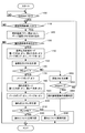
- FIG. 9 is a flowchart showing the details of leakage diagnosis control according to the embodiment.
- FIG. 3 is a schematic diagram showing an air flow in the evaporated fuel processing device in a reference pressure measurement mode according to one embodiment.
- FIG. 4 is a schematic diagram showing a flow of vapor and the like in the evaporated fuel processing apparatus in the leak measurement mode according to the embodiment.
- FIG. 6 is a schematic diagram showing a flow of vapor and the like in the evaporated fuel processing apparatus in the purge control mode according to the embodiment.
- FIG. 1 is a schematic diagram showing an engine system including an evaporated fuel processing device 20 mounted on a vehicle and a leakage diagnosis device thereof.
- the engine 1 includes an intake passage 3 for sucking air or the like into the combustion chamber 2, and an exhaust passage 4 for discharging exhaust gas from the combustion chamber 2.
- the fuel stored in the fuel tank 5 is supplied to the combustion chamber 2. That is, the fuel in the fuel tank 5 is discharged into the fuel passage 7 by the fuel pump 6 built in the tank 5, and is pressure-fed to the injector 8 provided in the intake port of the engine 1.
- the pressure-fed fuel is injected from the injector 8 and is introduced into the combustion chamber 2 together with the air (intake air) flowing through the intake passage 3 to form a combustible air-fuel mixture for combustion.
- the engine 1 is provided with an ignition device 9 for igniting a combustible mixture.
- An air cleaner 10, a throttle device 11, and a surge tank 12 are provided in the intake passage 3 from its inlet side to the engine 1.
- the throttle device 11 includes a throttle valve 11 a and is opened/closed to adjust the flow rate of intake air flowing through the intake passage 3.
- the opening/closing of the throttle valve 11a is interlocked with the operation of an accelerator pedal (not shown) by the driver.
- the surge tank 12 smoothes the intake pulsation in the intake passage 3.
- the evaporated fuel processing device 20 of this embodiment is configured to process the evaporated fuel (vapor) generated in the fuel tank 5 without releasing it into the atmosphere.
- This device 20 includes a canister 21 for collecting the vapor generated in the fuel tank 5, a vapor passage 22 for guiding the vapor from the fuel tank 5 to the canister 21, and an intake passage for the vapor collected in the canister 21.
- a purge passage 23 for introducing the purge gas into the intake passage 3, and an electric purge pump 24 provided in the purge passage 23 for pumping the vapor collected in the canister 21 to the intake passage 3 via the purge passage 23.
- the purge passage 23 includes an electric purge valve 25 for opening and closing the purge passage 23, and an atmosphere passage 26 for introducing the atmosphere into the canister 21.
- the canister 21 has a built-in adsorbent such as activated carbon for adsorbing vapor.
- the canister 21 includes an air inlet 21a for introducing the atmosphere, an inlet 21b for introducing the vapor, and an outlet 21c for leading out the vapor.
- One end of the vapor passage 22 is connected to the inlet 21b of the canister 21, and the other end of the vapor passage 22 communicates with the inside of the fuel tank 5.
- One end of the purge passage 23 is connected to the outlet 21c of the canister 21, and the other end is connected to the intake passage 3 between the throttle device 11 and the surge tank 12.
- One end of an atmosphere passage 26 is connected to the atmosphere port 21a of the canister 21, and an air filter 27 for collecting dust or the like in the air is provided at the other end.
- the inside of the canister 21 can communicate with the atmosphere via the atmosphere passage 26.
- the purge pump 24 includes a suction port 24a and a discharge port 24b, and is configured to suck the vapor collected in the canister 21 from the suction port 24a and discharge it from the discharge port 24b.
- the purge pump 24 is a centrifugal pump, and is configured to flow vapor or air only in one direction from the suction port 24a to the discharge port 24b.
- the engine system of this embodiment includes a leak diagnostic device for diagnosing a leak in the evaporated fuel processing device 20 described above.
- the leak diagnostic device is arranged in parallel between the purge passage 23 and the atmosphere passage 26, and the first bypass passage 28, the second bypass passage 29, and the reference provided in the first bypass passage 28.
- An orifice 30, a first three-way valve 31 provided at a first connecting portion that is a connecting portion between the purge passage 23 and the first bypass passage 28, and a connecting portion between the second bypass passage 29 and the atmosphere passage 26.
- a second three-way valve 32 provided in the second connection portion, a pressure sensor 47 provided in the purge passage 23 for detecting the passage pressure PP of the passage 23, and an electronic control unit (ECU) 50 are provided. ..
- the first bypass passage 28 is provided between the purge passage 23 upstream of the purge pump 24 and the atmosphere passage 26.
- the second bypass passage 29 is provided between the purge passage 23 upstream of the purge pump 24 and the atmosphere passage 26, and has one end connected to the purge passage 23 between the first three-way valve 31 and the purge pump 24. The end is connected to the atmosphere passage 26 at a second connection portion upstream of the connection portion between the atmosphere passage 26 and the first bypass passage 28.
- the reference orifice 30 provided in the first bypass passage 28 is for forming a reference pressure difference between the purge passage 23 and the atmosphere passage 26.
- the opening area of the reference orifice 30 is set to a predetermined reference value. In this embodiment, the reference value is set to an area that corresponds to, for example, “ ⁇ 0.5”.
- the first three-way valve 31 is a valve device that selectively switches communication between the purge passage 23 in the first connection portion or communication between the purge passage 23 and the first bypass passage 28 downstream of the first connection portion. This corresponds to an example of first communication switching means in the disclosed technology.
- the second three-way valve 32 selects communication between the atmosphere passage 26 and the second bypass passage 29 at the second connection portion between the atmosphere passage 26 and the second bypass passage 29 or communication between the atmosphere passage 26 at the second connection portion.
- the valve device is a valve device that dynamically switches, and corresponds to an example of a second communication switching unit in the disclosed technique.
- the pressure sensor 47 detects the passage pressure PP in the purge passage 23 between the purge pump 24 and the first three-way valve 31, and outputs an electric signal according to the detected value.
- a part of the purge passage 23, a part of the atmosphere passage 26, the first bypass passage 28, the second bypass passage 29, the reference orifice 30, the first three-way valve 31, and the second three-way valve 32 are It is integrally provided in one housing
- the ECU 50 controls the purge pump 24, the purge valve 25, the first three-way valve 31, and the second three-way valve 32, and also executes "leakage diagnosis control" for diagnosing a leak based on the detected passage pressure PP. It has become. Further, the ECU 50 executes purge control for purging vapor into the intake passage 3 by controlling the purge pump 24, the purge valve 25, the first three-way valve 31, and the second three-way valve 32 under predetermined conditions. It is supposed to do.
- each of the three-way valves 31 and 32 is electrically operated, and has a variable flow path configuration as will be described later.
- the first three-way valve 31 includes a first inlet 31a and an outlet 31b connected to the purge passage 23, and a second inlet 31c connected to the first bypass passage 28. Then, by switching the flow path of the first three-way valve 31, a first communication state in which the first inlet 31a and the outlet 31b communicate with each other and a second communication in which the second inlet 31c and the outlet 31b communicate with each other. The state can be switched to. In this embodiment, the first three-way valve 31 is turned off to switch to the first communication state, and the first three-way valve 31 is turned on to switch to the second communication state.
- the second three-way valve 32 also includes an inlet 32 a and a first outlet 32 b connected to the atmosphere passage 26, and a second outlet 32 c connected to the second bypass passage 29. Then, by switching the flow path of the second three-way valve 32, the first communication state in which the inlet 32a and the first outlet 32b communicate with each other and the second communication in which the first outlet 32b and the second outlet 32c communicate with each other. The state can be switched to. In this embodiment, the second three-way valve 32 is switched “OFF" to switch to the first communication state, and the second three-way valve 32 is switched "ON" to switch to the second communication state.
- various sensors 41 to 46 are provided in order to detect the operating state of the engine 1.
- the air flow meter 41 provided near the air cleaner 10 detects the amount of air taken into the intake passage 3 as the amount of intake air and outputs an electric signal according to the detected value.
- the throttle sensor 42 provided in the throttle device 11 detects the opening of the throttle valve 11a as the throttle opening and outputs an electric signal according to the detected value.
- the intake pressure sensor 43 provided in the surge tank 12 detects the pressure in the surge tank 12 as the intake pressure PM, and outputs an electric signal according to the detected value.
- the water temperature sensor 44 provided in the engine 1 detects the temperature of the cooling water flowing inside the engine 1 as the cooling water temperature THW and outputs an electric signal according to the detected value.
- a rotation speed sensor 45 provided in the engine 1 detects a rotation angular velocity of a crankshaft (not shown) of the engine 1 as an engine rotation speed, and outputs an electric signal according to the detected value.
- An air-fuel ratio sensor (A/F sensor) 46 provided in the exhaust passage 4 detects the hydrocarbon concentration HC in the exhaust and outputs an electric signal corresponding to the detected value.
- an ignition switch (IGSW) 48 and a warning lamp 56 are provided on the driver's seat of the vehicle.
- the IGSW 48 is operated by the driver to start the engine 1.
- the warning lamp 56 is turned on when the fuel vapor processing device 20 has a leak (a leak in the pipe or a malfunction of each of the three-way valves 31 and 32).
- an electronic control unit (ECU) 50 that manages various controls inputs various signals output from various sensors 41 to 48.
- the ECU 50 controls the injector 8, the ignition device 9, the purge pump 24, the purge valve 25, the first three-way valve 31, and the second three-way valve 32 based on these input signals to control fuel injection, ignition timing, and purge.
- the fuel temperature estimation process, the altitude estimation process, the vapor concentration estimation process, the leak diagnosis control, and the like are executed.
- the fuel injection control is to control the fuel injection amount and the fuel injection timing by controlling the injector 8 according to the operating state of the engine 1.
- the ignition timing control is to control the ignition timing of the combustible mixture by controlling the ignition device 9 according to the operating state of the engine 1.
- the purge control is performed by controlling the purge pump 24, the purge valve 25, the first three-way valve 31 and the second three-way valve 32 in the evaporated fuel processing apparatus 20 according to the operating state of the engine 1. That is, the vapor collected in the canister 21 is purged into the intake passage 3 via the purge passage 23.
- the fuel temperature estimation process is, for example, estimating the fuel temperature TF in the fuel tank 5 based on the cooling water temperature THW detected by the water temperature sensor 44. If a few hours have passed after the engine 1 was stopped, the cooling water temperature THW becomes substantially equal to the outside air temperature and the fuel temperature TF, so this estimation can be performed from the cooling water temperature THW.
- the water temperature sensor 44 and the ECU 50 correspond to means for estimating the fuel temperature TF (fuel temperature estimating means).
- the altitude estimation processing is, for example, estimating the altitude AL at which the vehicle stops based on the passage pressure PP detected by the pressure sensor 47.
- the pressure sensor 47 and the ECU 50 correspond to means for estimating the altitude AL.
- the vapor concentration estimation processing is, for example, estimating the vapor concentration DV adsorbed in the canister 21 based on the hydrocarbon concentration HC detected by the A/F sensor 46.
- the A/F sensor 46 and the ECU 50 correspond to a means (evaporated fuel concentration estimation means) for estimating the vapor concentration (evaporated fuel concentration).
- evaporated fuel concentration estimation means for estimating the vapor concentration (evaporated fuel concentration).
- the ECU 50 corresponds to an example of control means in the disclosed technique.
- the ECU 50 has a known configuration including a central processing unit (CPU), a read only memory (ROM), a random access memory (RAM), a backup RAM and the like.
- the ROM stores in advance a predetermined control program relating to the various controls described above.
- the ECU (CPU) 50 is adapted to execute the various controls described above in accordance with these control programs.
- FIG. 2 shows a flow chart of the control contents.
- the ECU 50 periodically executes this routine at predetermined time intervals.
- step 100 the ECU 50 waits for the IGSW 48 to turn off, that is, waits for the engine 1 to stop, and then shifts to step 110.
- step 110 the ECU 50 waits for a predetermined time after the engine 1 is stopped and proceeds to step 120.
- the ECU 50 takes in the estimated fuel temperature TF, altitude AL and vapor concentration DV.
- step 130 the ECU 50 determines whether or not the leak diagnosis condition is satisfied.
- the fuel temperature TF falls within a predetermined range
- the altitude AL falls below a predetermined height
- the vapor concentration DV falls below a predetermined value
- the ECU 50 sets the "reference pressure measurement mode". That is, the ECU 50 sets the first three-way valve 31 to “on”, the second three-way valve 32 to “off”, the purge pump 24 to “on”, controls the pump 24 to a constant rotation speed, and controls the purge valve 25. Set to "ON” to control the vapor purge to a constant flow rate.
- the reference pressure PB described later is adjusted by controlling the purge pump 24 and the purge valve 25 so that the negative pressure of the purge pump 24 does not become too high.
- FIG. 3 is a schematic diagram showing an air flow (shown by a wavy arrow) in the evaporated fuel processing device 20 in the reference pressure measurement mode.
- the air sucked from the atmosphere into the atmosphere passage 26 includes the second three-way valve 32, the atmosphere passage 26, the first bypass passage 28, the reference orifice 30, the first three-way valve 31, the purge passage 23, and the purge. It flows from the outlet of the purge passage 23 to the intake passage 3 via the pump 24 and the purge valve 25.
- step 150 the ECU 50 measures the passage pressure PP detected by the pressure sensor 47 as the reference pressure PB.
- step 160 the ECU 50 determines whether or not the reference pressure PB is equal to or lower than the predetermined value P1. If the determination result is affirmative, the ECU 50 shifts the processing to step 170, and if the determination result is negative, the ECU 50 shifts the processing to step 240.
- the ECU 50 turns off the purge pump 24.
- step 180 the ECU 50 sets the "leakage measurement mode". That is, the ECU 50 turns on the first three-way valve 31 and turns on the second three-way valve 32.
- step 190 the purge pump 24 is turned on and the purge valve 25 is turned on.
- FIG. 4 is a schematic diagram showing the flow of vapor and the like (shown by a wavy arrow) in the evaporated fuel processing device 20 in the leak measurement mode.
- the vapor flowing from the canister 21 to the atmosphere passage 26 flows to the first bypass passage 28, the reference orifice 30, the first three-way valve 31, and the purge passage 23, and at the same time, the second three-way valve 32 and the second passage.
- the vapor flowing through the first three-way valve 31 via the bypass passage 29 joins with the purge passage 23, and further flows from the outlet of the purge passage 23 to the intake passage 3 via the purge pump 24 and the purge valve 25.
- step 200 the ECU 50 measures the leak pressure PL based on the detection value of the pressure sensor 47.
- step 210 the ECU 50 determines whether the leak pressure PL is equal to or lower than the reference pressure PB.
- the ECU 50 shifts the processing to step 220 when the determination result is affirmative, and shifts the processing to step 230 when the determination result is negative.
- the ECU 50 determines that the leakage is normal and ends the subsequent processing. At this time, the ECU 50 can store the normality determination in the memory, for example.
- step 230 the ECU 50 determines that the leakage is abnormal and ends the subsequent processing.
- the ECU 50 can execute an abnormality notifying operation such as storing the abnormality determination in the memory or blinking the warning lamp 56, for example.
- step 240 after shifting from step 160, the ECU 50 adds the number Nt of times when the determination in step 160 is “NO”.
- step 250 the ECU 50 determines whether or not the number of times Nt is a predetermined value N1 or more.
- This predetermined value N1 can be set to "several times". If the determination result is affirmative, the ECU 50 shifts the process to step 260, and if the determination result is negative, returns the process to step 110.
- the ECU 50 determines that the leakage diagnosis device has a failure, and temporarily ends the subsequent processing.
- the failure of the leak diagnosis device for example, a failure of the purge pump 24, a closed failure in which the purge valve 25 is stuck in a closed state, or the like can be assumed.
- the ECU 50 can execute a failure notification operation such as storing the failure determination in the memory or blinking the warning lamp 56.
- the ECU 50 causes the first three-way valve 31 (first communication switching) to be performed when the purge pump 24 and the purge valve 25 are operating (when they are “ON”) under predetermined conditions.
- Means) and the second three-way valve 32 (second communication switching means) to control the reference pressure measurement mode in which the atmospheric pressure is sent to the intake passage 3 through the reference orifice 30, the purge pump 24 and the purge valve 25.
- a leak measurement mode in which the vapor collected in the canister 21 is pressure-fed to the intake passage 3 through the reference orifice 30, the purge pump 24, and the purge valve 25 is sequentially set, and a passage detected when the reference pressure measurement mode is set.
- FIG. 5 is a schematic diagram showing the flow of the vapor and the like (shown by a dashed arrow) in the evaporated fuel processing apparatus 20 in the purge control mode.
- each of the first three-way valve 31 and the second three-way valve 32 is turned “off” when the purge pump 24 and the purge valve 25 are operated.
- the vapor flowing out from the canister 21 to the purge passage 23 flows from the outlet of the purge passage 23 to the intake passage 3 via the first three-way valve 31, the purge pump 24 and the purge valve 25.
- the air sucked from the atmosphere into the atmosphere passage 26 is sucked into the canister 21 via the second three-way valve 32 and the atmosphere passage 26, and the inside of the canister 21 is scavenged as the vapor is discharged.
- the purge pump 24 that is originally used to pump the vapor to the intake passage 3 is used, and the purge upstream of the purge pump 24 is used.
- a first bypass passage 28, a second bypass passage 29, a reference orifice 30, a first three-way valve 31 (first communication switching means), a second three-way valve 32 (second communication switching). Means) and a pressure sensor 47 and only by comparing the reference pressure PB measured when the reference pressure measurement mode is set with the leakage pressure PL measured in the leakage measurement mode, the leakage in the evaporated fuel treatment device 20 can be prevented. To be diagnosed. Therefore, it is not necessary to separately provide a dedicated pump for leak diagnosis.
- the purge pump 24 is provided in the purge passage 23, the flow of vapor from the canister 21 to the purge pump 24 is blocked by the first three-way valve 31, and the second three-way provided on the side of the atmosphere passage 26 where vapor hardly flows.
- the second bypass passage 29 is connected to the suction side of the purge pump 24 via the valve 32, and the inside of the canister 21 is set to a negative pressure. Therefore, it is possible to omit the pump dedicated to the leak diagnosis, and it is possible to perform the effective leak diagnosis while suppressing an increase in the number of parts of the leak diagnosis apparatus and the complication of the configuration.
- the flow is passed through an orifice corresponding to the opening area of the reference orifice 30 to prevent leakage at atmospheric pressure at a high altitude.
- the pressure PL By comparing the pressure PL with the reference pressure PB at a high altitude location, it is possible to make an effective determination regarding leakage. Therefore, the accuracy of leak diagnosis can be improved.
- the predetermined condition for the leakage diagnosis includes the case where the fuel temperature TF is equal to or lower than the predetermined value, so that the fuel temperature TF is equal to or lower than the predetermined value, that is, the atmosphere passage of the vapor. Diagnosis of the leak will be made with less release to 26. For this reason, it is possible to suppress the release of vapor to the atmosphere during the leakage diagnosis.
- the predetermined condition for leakage diagnosis includes the case where the vapor concentration DV is equal to or lower than the predetermined value, so that the vapor concentration DV is equal to or lower than the predetermined value, that is, the atmosphere passage of the vapor. Diagnosis of the leak is made with less release to 26. For this reason, it is possible to suppress the release of vapor to the atmosphere during the leakage diagnosis.
- a part of the purge passage 23, a part of the atmosphere passage 26, the first bypass passage 28, the second bypass passage 29, the first three-way valve 31, and the second three-way valve 32 are combined into one. It is provided integrally with the housing. For this reason, for example, since the leak diagnostic device is configured by only providing the canister 21 with one integrated housing, it is possible to save space in the device.
- the first communication switching means is constituted by the first three-way valve 31 and the second communication switching means is constituted by the second three-way valve 32. It can also be configured by combining on-off valves.
- the first communication switching means is configured by a first opening/closing valve provided in the purge passage downstream of the first connection portion and a second opening/closing valve provided in the first bypass passage upstream of the first connection. can do.
- the second communication switching means is composed of a third opening/closing valve provided in the atmosphere passage upstream of the second connection portion and a fourth opening/closing valve provided in the second bypass passage downstream of the second connection. can do.
- the means for estimating the fuel temperature TF in the fuel tank 5 is provided, but means for detecting the fuel temperature TF, for example, a fuel temperature sensor may be provided.
- the means for estimating the vapor concentration DV of the vapor collected in the canister 21 is provided.
- the means for detecting the vapor concentration DV for example, the vapor concentration sensor is provided. You can also
- the purge passage 23 is connected to the intake passage 3 downstream of the throttle valve 11a to purge the vapor.
- the purge passage can be connected to the intake passage upstream of the throttle valve and downstream of the air flow meter to purge the vapor.
- the disclosed technology can be applied to an engine system configured to supply fuel from a fuel tank to the engine.
- Fuel Tank 20 Evaporative Fuel Processor 21 Canister 21a Atmosphere 21b Inlet 21c Outlet 23 Purge Passage 24 Purge Pump 26 Atmosphere Passage 28 First Bypass Passage 29 Second Bypass Passage 30 Reference Orifice 31 First Three Ways Valve (first communication switching means) 32 2nd three-way valve (first communication switching means) 44 Water temperature sensor (fuel temperature estimation means) 46 A/F sensor (evaporative fuel concentration estimation means) 47 Pressure sensor (pressure detection means) 50 ECU (control means, fuel temperature estimation means, evaporated fuel concentration estimation means)
Abstract
An evaporated fuel treatment apparatus 20 is provided with: a canister 21; a purge passage 23; a purge pump 24 provided in the purge passage 23; and an atmospheric air passage 26 communicating with the canister 21. A leakage diagnostic device is provided with: two bypass passages 28, 29 provided between the purge passage 23 on the upstream side of the purge pump 24 and the atmospheric air passage 26; a reference orifice 30; two three-way valves 31, 32; a pressure sensor 47; and an ECU 50. When operating the purge pump 24 under a predetermined condition, the ECU 50 controls the two three-way valves 31, 32 to set a mode in which atmospheric air is pressure-fed into an air intake passage 3 through the reference orifice 30 and the purge pump 24, and a mode in which vapors in the canister 21 are pressure-fed into the air intake passage 3 through the reference orifice 30 and the purge pump 24, and determines leakage by comparing a reference pressure and a leakage pressure that are measured when these modes are set.
Description
この明細書に開示される技術は、燃料タンクで発生する蒸発燃料を吸気通路へパージして処理する蒸発燃料処理装置における漏れを診断する蒸発燃料処理装置の漏れ診断装置に関する。
The technology disclosed in this specification relates to a leak diagnosis device for an evaporated fuel processing device for diagnosing a leak in an evaporated fuel processing device that purges evaporated fuel generated in a fuel tank into an intake passage for processing.
従来、この種の技術として、例えば、下記の特許文献1に記載の「蒸発燃料処理装置の漏れ検出装置」が知られている。この装置は、漏れ検出のために使用する専用の電動ポンプを備え、燃料タンクで発生する燃料蒸気(蒸発燃料)を吸着するキャニスタを含む通気装置における蒸発燃料の漏れを検出するようになっている。この装置は、電動ポンプの作動による加圧力又は減圧力に応じて通気装置の内部と外部との間で圧力差を形成することにより、通気装置の漏れ状態を検査するように構成される。ここで、この装置は、上記圧力差を比較するための基準オリフィスを備え、その基準オリフィスに、加圧力又は減圧力を印加して基準圧力差を形成し、その基準圧力差を検出する手段を有し、検出した基準圧力差が所定の圧力差になるように、電動モータ(モータ部)の回転速度(回転数)を補正する手段を備える。
Conventionally, as this type of technology, for example, a “leakage detection device for an evaporated fuel processing device” described in Patent Document 1 below is known. This device is provided with a dedicated electric pump used for leak detection, and is adapted to detect a leak of vaporized fuel in a ventilation device including a canister that adsorbs fuel vapor (vaporized fuel) generated in a fuel tank. .. This device is configured to inspect a leak state of the ventilating device by forming a pressure difference between the inside and the outside of the ventilating device in response to a pressurizing force or a depressurizing force generated by the operation of the electric pump. Here, this device is provided with a reference orifice for comparing the pressure difference, and a means for detecting the reference pressure difference by forming a reference pressure difference by applying a pressing force or a pressure reducing force to the reference orifice. A unit is provided that corrects the rotation speed (rotation speed) of the electric motor (motor unit) so that the detected reference pressure difference becomes a predetermined pressure difference.
ところが、特許文献1に記載の装置では、漏れ検出のために専用の電動ポンプが必要になるため、漏れ検出以外の用途、例えば、蒸発燃料を吸気通路へパージするための用途で電動ポンプ(パージポンプ)を設けた場合には、漏れ検出専用の電動ポンプが別途必要になる。そのため、装置全体の部品点数が増えると共に構成が複雑化し、装置の製造コストが増すおそれがあった。
However, the device described in Patent Document 1 requires a dedicated electric pump for leak detection. Therefore, the electric pump (purge) is used for applications other than leak detection, for example, for purging evaporated fuel into the intake passage. If a pump is provided, an electric pump dedicated to leak detection is required separately. Therefore, the number of parts of the entire device increases, the configuration becomes complicated, and the manufacturing cost of the device may increase.
この開示技術は、上記事情に鑑みてなされたものであって、その目的は、漏れ診断専用ポンプを省略し、漏れ診断装置の部品点数の増加と構成の複雑化を抑えながら有効な漏れ診断を行うことを可能とした蒸発燃料処理装置の漏れ診断装置を提供することにある。
The disclosed technology has been made in view of the above circumstances, and an object thereof is to perform an effective leak diagnosis while omitting the leak diagnosis dedicated pump and suppressing an increase in the number of parts of the leak diagnosis apparatus and the complication of the configuration. It is an object of the present invention to provide a leak diagnostic device for an evaporated fuel processing device that is capable of being performed.
(1)上記目的を達成するために、本発明の一態様は、燃料タンクで発生する蒸発燃料をエンジンの吸気通路へパージして処理する蒸発燃料処理装置における漏れを診断する漏れ診断装置において、蒸発燃料処理装置は、燃料タンクで発生する蒸発燃料を捕集するためのキャニスタと、キャニスタは、燃料タンクから蒸発燃料を導入するための導入口と、キャニスタから蒸発燃料を導出するための導出口と、キャニスタに大気を導入するための大気口とを含むことと、キャニスタに捕集された蒸発燃料を導出口から吸気通路へ導くためのパージ通路と、パージ通路に設けられ、キャニスタに捕集された蒸発燃料をパージ通路を介して吸気通路へ圧送するためのパージポンプと、キャニスタの大気口に大気を導入するための大気通路とを備え、漏れ診断装置は、パージポンプより上流のパージ通路と大気通路との間に接続された第1バイパス通路と、パージポンプより上流のパージ通路と大気通路との間にて第1バイパス通路と並列に配置され、一端が第1バイパス通路とパージ通路との第1の接続部より下流のパージ通路に接続され、他端が大気通路と第1バイパス通路との接続部より上流の大気通路に接続された第2バイパス通路と、第1バイパス通路に設けられ、パージ通路と大気通路との間に圧力差を形成するための基準オリフィスと、第1の接続部におけるパージ通路の連通又は第1の接続部より下流のパージ通路と第1バイパス通路との連通を選択的に切り替えるための第1の連通切り替え手段と、大気通路と第2バイパス通路との第2の接続部における大気通路と第2バイパス通路との連通又は第2の接続部における大気通路の連通を選択的に切り替えるための第2の連通切り替え手段と、パージポンプと第1の接続部との間のパージ通路の通路圧力を検出するための圧力検出手段と、パージポンプ、第1の連通切り替え手段及び第2の連通切り替え手段を制御すると共に、検出される通路圧力に基づき漏れを診断するための制御手段とを備え、制御手段は、所定の条件の下で、パージポンプの作動時に、第1の連通切り替え手段及び第2の連通切り替え手段を制御することにより、大気を基準オリフィスとパージポンプを介して吸気通路へ圧送する基準圧力計測モードと、キャニスタに捕集された蒸発燃料を基準オリフィス及びパージポンプを介して吸気通路へ圧送する漏れ計測モードとを順次設定すると共に、基準圧力計測モードの設定時に検出される通路圧力に基づき基準圧力を計測し、漏れ計測モードの設定時に検出される通路圧力に基づき漏れ圧力を計測し、計測される基準圧力と計測される漏れ圧力とを比較することにより漏れの有無を判定することを趣旨とする。
(1) In order to achieve the above object, one aspect of the present invention is a leak diagnostic device for diagnosing a leak in an evaporated fuel processing device that purges evaporated fuel generated in a fuel tank into an intake passage of an engine for processing. The evaporated fuel processing device is a canister for collecting evaporated fuel generated in a fuel tank, a canister is an inlet for introducing evaporated fuel from the fuel tank, and an outlet for discharging evaporated fuel from the canister. And an atmosphere port for introducing the atmosphere into the canister, a purge passage for guiding the evaporated fuel collected in the canister from the outlet to the intake passage, and a purge passage provided in the purge passage for collecting in the canister. The leak diagnosis device includes a purge passage upstream of the purge pump, and a purge pump for pumping the vaporized fuel thus formed to the intake passage through the purge passage, and an atmosphere passage for introducing the atmosphere into the atmosphere opening of the canister. A first bypass passage connected between the first bypass passage and the atmosphere passage, and arranged in parallel with the first bypass passage between the purge passage upstream of the purge pump and the atmosphere passage, and one end of the first bypass passage and the purge passage. A first bypass passage and a second bypass passage connected to a purge passage downstream of a first connection portion between the first bypass passage and the other end, and the other end connected to an atmosphere passage upstream of a connection portion between the atmosphere passage and the first bypass passage. A reference orifice provided for forming a pressure difference between the purge passage and the atmosphere passage, the purge passage communicating with the first connecting portion, or the purge passage downstream of the first connecting portion and the first bypass passage. Communication means for selectively switching the communication between the air passage and the second bypass passage between the atmosphere passage and the second bypass passage, or the atmosphere at the second connection portion. Second communication switching means for selectively switching communication between the passages, pressure detecting means for detecting passage pressure in the purge passage between the purge pump and the first connection portion, purge pump, first Control means for controlling the communication switching means and the second communication switching means, and for diagnosing a leak based on the detected passage pressure. The control means operates the purge pump under a predetermined condition. At the time, by controlling the first communication switching means and the second communication switching means, a reference pressure measurement mode in which the atmosphere is pressure-fed to the intake passage through the reference orifice and the purge pump, and the evaporated fuel collected in the canister When the leak measurement mode in which the pressure is sent to the intake passage through the reference orifice and the purge pump is set sequentially, In both cases, the reference pressure is measured based on the passage pressure detected when the reference pressure measurement mode is set, and the leakage pressure is measured based on the passage pressure detected when the leak measurement mode is set. The purpose is to determine the presence or absence of leakage by comparing it with the leakage pressure.
上記(1)の構成によれば、本来、蒸発燃料を吸気通路へ圧送するために使用されるパージポンプが利用され、そのパージポンプより上流のパージ通路と大気通路に対し、第1バイパス通路、第2バイパス通路、基準オリフィス、第1の連通切り替え手段、第2の連通切り替え手段及び圧力検出手段が設けられ、基準圧力計測モード設定時に計測される基準圧力と、漏れ計測モードにて計測される漏れ圧力とを比較するだけで、蒸発燃料処理装置における漏れが診断される。従って、漏れ診断のために専用のポンプを別途設ける必要がない。また、パージ通路にパージポンプが設けられるが、第1の連通切り替え手段によりキャニスタからパージポンプへの蒸発燃料の流れが遮断され、蒸発燃料が流れ難い大気通路の側に設けられた第2の連通切り替え手段を介してパージポンプの吸入側に第2バイパス通路が接続され、キャニスタの内部が負圧に設定される。
According to the above configuration (1), the purge pump that is originally used to pump the evaporated fuel to the intake passage is used, and the first bypass passage and the purge passage upstream of the purge pump and the atmosphere passage are provided. A second bypass passage, a reference orifice, a first communication switching means, a second communication switching means, and a pressure detecting means are provided, and the reference pressure measured when the reference pressure measurement mode is set and the leak measurement mode are measured. Only by comparing the leak pressure with the leak pressure, a leak in the fuel vapor processing apparatus can be diagnosed. Therefore, it is not necessary to separately provide a dedicated pump for leak diagnosis. Further, although the purge pump is provided in the purge passage, the flow of the evaporated fuel from the canister to the purge pump is blocked by the first communication switching means, and the second communication provided in the side of the atmospheric passage where the evaporated fuel does not easily flow. The second bypass passage is connected to the suction side of the purge pump via the switching means, and the inside of the canister is set to a negative pressure.
(2)上記目的を達成するために、上記(1)の構成において、基準オリフィスの開口面積が所定の基準値に設定されたことを趣旨とする。
(2) In order to achieve the above object, it is meant that the opening area of the reference orifice is set to a predetermined reference value in the configuration of (1) above.
上記(2)の構成によれば、上記(1)の構成の作用に加え、例えば、標高が高い場所に駐車して漏れ診断を行う場合でも、基準オリフィスの開口面積に相当するオリフィスに流れを通過させ、標高が高い場所の気圧における漏れ圧力を、標高が高い場所における基準圧力と比較することで、漏れに関する有効な判定が可能となる。
According to the configuration of the above (2), in addition to the operation of the configuration of the above (1), for example, even when the vehicle is parked at a high altitude and leakage diagnosis is performed, the flow is applied to the orifice corresponding to the opening area of the reference orifice. By allowing the gas to pass through and comparing the leak pressure at atmospheric pressure at a high altitude with the reference pressure at a high altitude, it is possible to make an effective determination regarding leak.
(3)上記目的を達成するために、上記(1)又は2の構成において、燃料タンクの中の燃料温度を検出又は推定するため手段を更に備え、所定の条件は、検出又は推定される燃料温度が所定値以下となる場合を含むことを趣旨とする。
(3) In order to achieve the above object, in the configuration of (1) or 2, there is further provided means for detecting or estimating the fuel temperature in the fuel tank, and the predetermined condition is the fuel to be detected or estimated. It is intended to include cases where the temperature is below a predetermined value.
上記(3)の構成によれば、上記(1)又は2の構成の作用に加え、燃料温度が所定値以下となる状態、すなわち、蒸発燃料の大気通路への放出が少なくなる状態で、漏れの診断が行われる。
According to the configuration of the above (3), in addition to the action of the configuration of the above (1) or 2, in the state where the fuel temperature is equal to or lower than a predetermined value, that is, in the state where the evaporated fuel is less discharged to the atmosphere passage, the leakage Is diagnosed.
(4)上記目的を達成するために、上記(1)乃至(3)のいずれかの構成において、キャニスタに捕集された蒸発燃料の濃度を検出又は推定するための手段を更に備え、所定の条件は、検出又は推定される蒸発燃料の濃度が所定値以下となる場合を含むことを趣旨とする。
(4) In order to achieve the above object, in any one of the configurations (1) to (3), a unit for detecting or estimating the concentration of the evaporated fuel trapped in the canister is further provided, and the predetermined unit is provided. The condition is intended to include the case where the detected or estimated concentration of the evaporated fuel is equal to or lower than a predetermined value.
上記(4)の構成によれば、上記(1)乃至(3)のいずれかの構成の作用に加え、蒸発燃料の濃度が所定値以下となる状態、すなわち、蒸発燃料の大気通路への放出が少なくなる状態で、漏れの診断が行われる。
According to the configuration of (4) above, in addition to the operation of any one of the configurations of (1) to (3), the concentration of the evaporated fuel becomes equal to or lower than a predetermined value, that is, the evaporated fuel is released into the atmosphere passage. Leakage is diagnosed with less loss.
上記(1)の構成によれば、漏れ診断専用のポンプを省略することができ、漏れ診断装置の部品点数の増加と構成の複雑化を抑えながら有効な漏れ診断を行うことができる。
According to the configuration of (1) above, a pump dedicated to leak diagnosis can be omitted, and effective leak diagnosis can be performed while suppressing an increase in the number of parts of the leak diagnosis device and complicating the configuration.
上記(2)の構成によれば、上記(1)の構成の効果に加え、漏れ診断精度を向上させることができる。
According to the configuration of (2) above, in addition to the effect of the configuration of (1) above, the accuracy of leak diagnosis can be improved.
上記(3)の構成によれば、上記(1)又は2の構成の効果に加え、漏れ診断の際に大気への蒸発燃料の放出を抑制することができる。
According to the configuration of (3) above, in addition to the effect of the configuration of (1) or 2, it is possible to suppress the release of evaporated fuel to the atmosphere during leak diagnosis.
上記(4)の構成によれば、上記(1)乃至(3)のいずれかの構成の効果に加え、漏れ診断の際に大気への蒸発燃料の放出を抑制することができる。
According to the configuration of (4) above, in addition to the effect of any one of the configurations of (1) to (3) above, it is possible to suppress the release of evaporated fuel to the atmosphere at the time of leak diagnosis.
以下、蒸発燃料処理装置の漏れ診断装置を具体化した一実施形態につき図面を参照して詳細に説明する。
Hereinafter, an embodiment embodying a leak diagnosis device for an evaporated fuel processing device will be described in detail with reference to the drawings.
[エンジンシステムの概要について]
図1に、車両に搭載された蒸発燃料処理装置20とその漏れ診断装置を含むエンジンシステムを概略図により示す。エンジン1は、燃焼室2に空気等を吸入させるための吸気通路3と、燃焼室2から排気を排出させるための排気通路4とを備える。燃焼室2には、燃料タンク5に貯留された燃料が供給される。すなわち、燃料タンク5の燃料は、同タンク5に内蔵された燃料ポンプ6により燃料通路7へ吐出され、エンジン1の吸気ポートに設けられたインジェクタ8へ圧送される。圧送された燃料は、インジェクタ8から噴射され、吸気通路3を流れる空気(吸気)と共に燃焼室2に導入されて可燃混合気を形成し、燃焼に供される。エンジン1には、可燃混合気を点火するための点火装置9が設けられる。 [Outline of engine system]
FIG. 1 is a schematic diagram showing an engine system including an evaporatedfuel processing device 20 mounted on a vehicle and a leakage diagnosis device thereof. The engine 1 includes an intake passage 3 for sucking air or the like into the combustion chamber 2, and an exhaust passage 4 for discharging exhaust gas from the combustion chamber 2. The fuel stored in the fuel tank 5 is supplied to the combustion chamber 2. That is, the fuel in the fuel tank 5 is discharged into the fuel passage 7 by the fuel pump 6 built in the tank 5, and is pressure-fed to the injector 8 provided in the intake port of the engine 1. The pressure-fed fuel is injected from the injector 8 and is introduced into the combustion chamber 2 together with the air (intake air) flowing through the intake passage 3 to form a combustible air-fuel mixture for combustion. The engine 1 is provided with an ignition device 9 for igniting a combustible mixture.
図1に、車両に搭載された蒸発燃料処理装置20とその漏れ診断装置を含むエンジンシステムを概略図により示す。エンジン1は、燃焼室2に空気等を吸入させるための吸気通路3と、燃焼室2から排気を排出させるための排気通路4とを備える。燃焼室2には、燃料タンク5に貯留された燃料が供給される。すなわち、燃料タンク5の燃料は、同タンク5に内蔵された燃料ポンプ6により燃料通路7へ吐出され、エンジン1の吸気ポートに設けられたインジェクタ8へ圧送される。圧送された燃料は、インジェクタ8から噴射され、吸気通路3を流れる空気(吸気)と共に燃焼室2に導入されて可燃混合気を形成し、燃焼に供される。エンジン1には、可燃混合気を点火するための点火装置9が設けられる。 [Outline of engine system]
FIG. 1 is a schematic diagram showing an engine system including an evaporated
吸気通路3には、その入口側からエンジン1にかけて、エアクリーナ10、スロットル装置11及びサージタンク12が設けられる。スロットル装置11は、スロットル弁11aを含み、吸気通路3を流れる吸気流量を調節するために開閉される。スロットル弁11aの開閉は、運転者によるアクセルペダル(図示略)の操作に連動する。サージタンク12は、吸気通路3における吸気脈動を平滑化させる。
An air cleaner 10, a throttle device 11, and a surge tank 12 are provided in the intake passage 3 from its inlet side to the engine 1. The throttle device 11 includes a throttle valve 11 a and is opened/closed to adjust the flow rate of intake air flowing through the intake passage 3. The opening/closing of the throttle valve 11a is interlocked with the operation of an accelerator pedal (not shown) by the driver. The surge tank 12 smoothes the intake pulsation in the intake passage 3.
[蒸発燃料処理装置の構成について]
図1において、この実施形態の蒸発燃料処理装置20は、燃料タンク5で発生する蒸発燃料(ベーパ)を大気中へ放出させることなく処理するように構成される。この装置20は、燃料タンク5で発生するベーパを捕集するためのキャニスタ21と、燃料タンク5からキャニスタ21へベーパを導くためのベーパ通路22と、キャニスタ21に捕集されたベーパを吸気通路3へ導いてパージするためのパージ通路23と、パージ通路23に設けられ、キャニスタ21に捕集されたベーパをパージ通路23を介して吸気通路3へ圧送するための電動式のパージポンプ24と、パージ通路23に設けられ、パージ通路23を開閉するための電動式のパージ弁25と、キャニスタ21に大気を導入するための大気通路26とを備える。 [Configuration of Evaporative Fuel Processing Device]
In FIG. 1, the evaporatedfuel processing device 20 of this embodiment is configured to process the evaporated fuel (vapor) generated in the fuel tank 5 without releasing it into the atmosphere. This device 20 includes a canister 21 for collecting the vapor generated in the fuel tank 5, a vapor passage 22 for guiding the vapor from the fuel tank 5 to the canister 21, and an intake passage for the vapor collected in the canister 21. A purge passage 23 for introducing the purge gas into the intake passage 3, and an electric purge pump 24 provided in the purge passage 23 for pumping the vapor collected in the canister 21 to the intake passage 3 via the purge passage 23. The purge passage 23 includes an electric purge valve 25 for opening and closing the purge passage 23, and an atmosphere passage 26 for introducing the atmosphere into the canister 21.
図1において、この実施形態の蒸発燃料処理装置20は、燃料タンク5で発生する蒸発燃料(ベーパ)を大気中へ放出させることなく処理するように構成される。この装置20は、燃料タンク5で発生するベーパを捕集するためのキャニスタ21と、燃料タンク5からキャニスタ21へベーパを導くためのベーパ通路22と、キャニスタ21に捕集されたベーパを吸気通路3へ導いてパージするためのパージ通路23と、パージ通路23に設けられ、キャニスタ21に捕集されたベーパをパージ通路23を介して吸気通路3へ圧送するための電動式のパージポンプ24と、パージ通路23に設けられ、パージ通路23を開閉するための電動式のパージ弁25と、キャニスタ21に大気を導入するための大気通路26とを備える。 [Configuration of Evaporative Fuel Processing Device]
In FIG. 1, the evaporated
キャニスタ21は、ベーパを吸着するための活性炭等の吸着材を内蔵する。キャニスタ21は、大気を導入する大気口21aと、ベーパを導入する導入口21bと、ベーパを導出する導出口21cとを含む。キャニスタ21の導入口21bには、ベーパ通路22の一端が接続され、同通路22の他端は、燃料タンク5の内部に連通する。キャニスタ21の導出口21cには、パージ通路23の一端が接続され、その他端はスロットル装置11とサージタンク12との間の吸気通路3に接続される。キャニスタ21の大気口21aには、大気通路26の一端が接続され、その他端には、空気中の粉塵等を捕集するためのエアフィルタ27が設けられる。キャニスタ21の内部は、大気通路26を介して大気に連通可能である。
The canister 21 has a built-in adsorbent such as activated carbon for adsorbing vapor. The canister 21 includes an air inlet 21a for introducing the atmosphere, an inlet 21b for introducing the vapor, and an outlet 21c for leading out the vapor. One end of the vapor passage 22 is connected to the inlet 21b of the canister 21, and the other end of the vapor passage 22 communicates with the inside of the fuel tank 5. One end of the purge passage 23 is connected to the outlet 21c of the canister 21, and the other end is connected to the intake passage 3 between the throttle device 11 and the surge tank 12. One end of an atmosphere passage 26 is connected to the atmosphere port 21a of the canister 21, and an air filter 27 for collecting dust or the like in the air is provided at the other end. The inside of the canister 21 can communicate with the atmosphere via the atmosphere passage 26.
この実施形態で、パージポンプ24は、吸入口24aと吐出口24bとを含み、キャニスタ21に捕集されたベーパを吸入口24aから吸入し、吐出口24bから吐出するように構成される。また、パージポンプ24は、遠心ポンプにより構成され、吸入口24aから吐出口24bへ向かう一方向へのみベーパ又は空気を流すように構成される。
In this embodiment, the purge pump 24 includes a suction port 24a and a discharge port 24b, and is configured to suck the vapor collected in the canister 21 from the suction port 24a and discharge it from the discharge port 24b. The purge pump 24 is a centrifugal pump, and is configured to flow vapor or air only in one direction from the suction port 24a to the discharge port 24b.
[漏れ診断装置の構成について]
この実施形態のエンジンシステムは、上記した蒸発燃料処理装置20における漏れを診断するための漏れ診断装置を備える。図1に示すように、漏れ診断装置は、パージ通路23と大気通路26との間に並列に配置され第1バイパス通路28及び第2バイパス通路29と、第1バイパス通路28に設けられた基準オリフィス30と、パージ通路23と第1バイパス通路28との接続部である第1の接続部に設けられた第1三方弁31と、第2バイパス通路29と大気通路26との接続部である第2の接続部に設けられた第2三方弁32と、パージ通路23に設けられて同通路23の通路圧力PPを検出するための圧力センサ47と、電子制御装置(ECU)50とを備える。 [About the configuration of the leak diagnostic device]
The engine system of this embodiment includes a leak diagnostic device for diagnosing a leak in the evaporatedfuel processing device 20 described above. As shown in FIG. 1, the leak diagnostic device is arranged in parallel between the purge passage 23 and the atmosphere passage 26, and the first bypass passage 28, the second bypass passage 29, and the reference provided in the first bypass passage 28. An orifice 30, a first three-way valve 31 provided at a first connecting portion that is a connecting portion between the purge passage 23 and the first bypass passage 28, and a connecting portion between the second bypass passage 29 and the atmosphere passage 26. A second three-way valve 32 provided in the second connection portion, a pressure sensor 47 provided in the purge passage 23 for detecting the passage pressure PP of the passage 23, and an electronic control unit (ECU) 50 are provided. ..
この実施形態のエンジンシステムは、上記した蒸発燃料処理装置20における漏れを診断するための漏れ診断装置を備える。図1に示すように、漏れ診断装置は、パージ通路23と大気通路26との間に並列に配置され第1バイパス通路28及び第2バイパス通路29と、第1バイパス通路28に設けられた基準オリフィス30と、パージ通路23と第1バイパス通路28との接続部である第1の接続部に設けられた第1三方弁31と、第2バイパス通路29と大気通路26との接続部である第2の接続部に設けられた第2三方弁32と、パージ通路23に設けられて同通路23の通路圧力PPを検出するための圧力センサ47と、電子制御装置(ECU)50とを備える。 [About the configuration of the leak diagnostic device]
The engine system of this embodiment includes a leak diagnostic device for diagnosing a leak in the evaporated
第1バイパス通路28は、パージポンプ24より上流のパージ通路23と大気通路26との間に設けられる。第2バイパス通路29は、パージポンプ24より上流のパージ通路23と大気通路26との間に設けられ、一端が第1三方弁31とパージポンプ24との間のパージ通路23に接続され、他端が大気通路26と第1バイパス通路28との接続部より上流の第2の接続部にて大気通路26に接続される。第1バイパス通路28に設けられた基準オリフィス30は、パージ通路23と大気通路26との間に基準圧力差を形成するためのものである。この基準オリフィス30の開口面積は、所定の基準値に設定される。この実施形態で、その基準値は、例えば「φ0.5」相当に合致する面積に設定される。
The first bypass passage 28 is provided between the purge passage 23 upstream of the purge pump 24 and the atmosphere passage 26. The second bypass passage 29 is provided between the purge passage 23 upstream of the purge pump 24 and the atmosphere passage 26, and has one end connected to the purge passage 23 between the first three-way valve 31 and the purge pump 24. The end is connected to the atmosphere passage 26 at a second connection portion upstream of the connection portion between the atmosphere passage 26 and the first bypass passage 28. The reference orifice 30 provided in the first bypass passage 28 is for forming a reference pressure difference between the purge passage 23 and the atmosphere passage 26. The opening area of the reference orifice 30 is set to a predetermined reference value. In this embodiment, the reference value is set to an area that corresponds to, for example, “φ0.5”.
第1三方弁31は、第1の接続部におけるパージ通路23の連通又は第1の接続部より下流のパージ通路23と第1バイパス通路28との連通を選択的に切り替える弁装置であり、本開示技術における第1の連通切り替え手段の一例に相当する。第2三方弁32は、大気通路26と第2バイパス通路29との第2の接続部における大気通路26と第2バイパス通路29との連通又は第2の接続部における大気通路26の連通を選択的に切り替える弁装置であり、本開示技術における第2の連通切り替え手段の一例に相当する。圧力センサ47は、パージポンプ24と第1三方弁31との間のパージ通路23における通路圧力PPを検出し、その検出値に応じた電気信号を出力する。この実施形態では、上記したパージ通路23の一部、大気通路26の一部、第1バイパス通路28、第2バイパス通路29、基準オリフィス30、第1三方弁31及び第2三方弁32が、一つのハウジングに一体化して設けられる。
The first three-way valve 31 is a valve device that selectively switches communication between the purge passage 23 in the first connection portion or communication between the purge passage 23 and the first bypass passage 28 downstream of the first connection portion. This corresponds to an example of first communication switching means in the disclosed technology. The second three-way valve 32 selects communication between the atmosphere passage 26 and the second bypass passage 29 at the second connection portion between the atmosphere passage 26 and the second bypass passage 29 or communication between the atmosphere passage 26 at the second connection portion. The valve device is a valve device that dynamically switches, and corresponds to an example of a second communication switching unit in the disclosed technique. The pressure sensor 47 detects the passage pressure PP in the purge passage 23 between the purge pump 24 and the first three-way valve 31, and outputs an electric signal according to the detected value. In this embodiment, a part of the purge passage 23, a part of the atmosphere passage 26, the first bypass passage 28, the second bypass passage 29, the reference orifice 30, the first three-way valve 31, and the second three-way valve 32 are It is integrally provided in one housing.
ECU50は、パージポンプ24、パージ弁25、第1三方弁31及び第2三方弁32を制御すると共に、検出される通路圧力PPに基づき漏れを診断するための「漏れ診断制御」を実行するようになっている。また、ECU50は、所定の条件下で、パージポンプ24、パージ弁25、第1三方弁31及び第2三方弁32を制御することにより、吸気通路3へベーパをパージするためのパージ制御を実行するようになっている。
The ECU 50 controls the purge pump 24, the purge valve 25, the first three-way valve 31, and the second three-way valve 32, and also executes "leakage diagnosis control" for diagnosing a leak based on the detected passage pressure PP. It has become. Further, the ECU 50 executes purge control for purging vapor into the intake passage 3 by controlling the purge pump 24, the purge valve 25, the first three-way valve 31, and the second three-way valve 32 under predetermined conditions. It is supposed to do.
この実施形態で、各三方弁31,32は、それぞれ電動式であり、後述するように流路を切り替え可変に構成される。第1三方弁31は、パージ通路23に接続される第1入口31a及び出口31bと、第1バイパス通路28に接続される第2入口31cとを含む。そして、第1三方弁31の流路を切り替えることにより、その第1入口31aとその出口31bとを連通させる第1連通状態と、その第2入口31cとその出口31bとを連通させる第2連通状態とに切り替え可能に構成される。この実施形態では、第1三方弁31を「オフ」することにより、第1連通状態に切り替えられ、第1三方弁31を「オン」することにより、第2連通状態に切り替えられる。また、第2三方弁32は、大気通路26に接続される入口32a及び第1出口32bと第2バイパス通路29に接続される第2出口32cとを含む。そして、第2三方弁32の流路を切り替えることにより、その入口32aと第1出口32bとを連通させる第1連通状態と、その第1出口32bと第2出口32cとを連通させる第2連通状態とに切り替え可能に構成される。この実施形態では、第2三方弁32を「オフ」することにより、第1連通状態に切り替えられ、第2三方弁32を「オン」することにより、第2連通状態に切り替えられる。
In this embodiment, each of the three- way valves 31 and 32 is electrically operated, and has a variable flow path configuration as will be described later. The first three-way valve 31 includes a first inlet 31a and an outlet 31b connected to the purge passage 23, and a second inlet 31c connected to the first bypass passage 28. Then, by switching the flow path of the first three-way valve 31, a first communication state in which the first inlet 31a and the outlet 31b communicate with each other and a second communication in which the second inlet 31c and the outlet 31b communicate with each other. The state can be switched to. In this embodiment, the first three-way valve 31 is turned off to switch to the first communication state, and the first three-way valve 31 is turned on to switch to the second communication state. The second three-way valve 32 also includes an inlet 32 a and a first outlet 32 b connected to the atmosphere passage 26, and a second outlet 32 c connected to the second bypass passage 29. Then, by switching the flow path of the second three-way valve 32, the first communication state in which the inlet 32a and the first outlet 32b communicate with each other and the second communication in which the first outlet 32b and the second outlet 32c communicate with each other. The state can be switched to. In this embodiment, the second three-way valve 32 is switched "OFF" to switch to the first communication state, and the second three-way valve 32 is switched "ON" to switch to the second communication state.
上記構成において、パージポンプ24の吸入口24aに接続されるパージ通路23では、ベーパがパージポンプ24へ負圧により吸引され、パージポンプ24の吐出口24bに接続されるパージ通路23では、ベーパがパージポンプ24から正圧により押し出される。パージポンプ24による「圧送」とは、これら両方の作用を含むものとする。
In the above configuration, in the purge passage 23 connected to the suction port 24a of the purge pump 24, the vapor is sucked into the purge pump 24 by negative pressure, and in the purge passage 23 connected to the discharge port 24b of the purge pump 24, the vapor is removed. It is pushed out from the purge pump 24 by positive pressure. “Pressing” by the purge pump 24 includes both of these actions.
[エンジンシステムの電気的構成について]
この実施形態では、上記した圧力センサ47の他に、エンジン1の運転状態を検出するために、各種センサ等41~46が設けられる。エアクリーナ10の近くに設けられたエアフローメータ41は、吸気通路3に吸入される空気量を吸気量として検出し、その検出値に応じた電気信号を出力する。スロットル装置11に設けられたスロットルセンサ42は、スロットル弁11aの開度をスロットル開度として検出し、その検出値に応じた電気信号を出力する。サージタンク12に設けられた吸気圧センサ43は、サージタンク12の中の圧力を吸気圧力PMとして検出し、その検出値に応じた電気信号を出力する。エンジン1に設けられた水温センサ44は、エンジン1の内部を流れる冷却水の温度を冷却水温度THWとして検出し、その検出値に応じた電気信号を出力する。エンジン1に設けられた回転数センサ45は、エンジン1のクランクシャフト(図示略)の回転角速度をエンジン回転数として検出し、その検出値に応じた電気信号を出力する。排気通路4に設けられた空燃比センサ(A/Fセンサ)46は、排気中の炭化水素濃度HCを検出し、その検出値に応じた電気信号を出力する。 [About electrical configuration of engine system]
In this embodiment, in addition to thepressure sensor 47 described above, various sensors 41 to 46 are provided in order to detect the operating state of the engine 1. The air flow meter 41 provided near the air cleaner 10 detects the amount of air taken into the intake passage 3 as the amount of intake air and outputs an electric signal according to the detected value. The throttle sensor 42 provided in the throttle device 11 detects the opening of the throttle valve 11a as the throttle opening and outputs an electric signal according to the detected value. The intake pressure sensor 43 provided in the surge tank 12 detects the pressure in the surge tank 12 as the intake pressure PM, and outputs an electric signal according to the detected value. The water temperature sensor 44 provided in the engine 1 detects the temperature of the cooling water flowing inside the engine 1 as the cooling water temperature THW and outputs an electric signal according to the detected value. A rotation speed sensor 45 provided in the engine 1 detects a rotation angular velocity of a crankshaft (not shown) of the engine 1 as an engine rotation speed, and outputs an electric signal according to the detected value. An air-fuel ratio sensor (A/F sensor) 46 provided in the exhaust passage 4 detects the hydrocarbon concentration HC in the exhaust and outputs an electric signal corresponding to the detected value.
この実施形態では、上記した圧力センサ47の他に、エンジン1の運転状態を検出するために、各種センサ等41~46が設けられる。エアクリーナ10の近くに設けられたエアフローメータ41は、吸気通路3に吸入される空気量を吸気量として検出し、その検出値に応じた電気信号を出力する。スロットル装置11に設けられたスロットルセンサ42は、スロットル弁11aの開度をスロットル開度として検出し、その検出値に応じた電気信号を出力する。サージタンク12に設けられた吸気圧センサ43は、サージタンク12の中の圧力を吸気圧力PMとして検出し、その検出値に応じた電気信号を出力する。エンジン1に設けられた水温センサ44は、エンジン1の内部を流れる冷却水の温度を冷却水温度THWとして検出し、その検出値に応じた電気信号を出力する。エンジン1に設けられた回転数センサ45は、エンジン1のクランクシャフト(図示略)の回転角速度をエンジン回転数として検出し、その検出値に応じた電気信号を出力する。排気通路4に設けられた空燃比センサ(A/Fセンサ)46は、排気中の炭化水素濃度HCを検出し、その検出値に応じた電気信号を出力する。 [About electrical configuration of engine system]
In this embodiment, in addition to the
また、車両の運転席には、イグニションスイッチ(IGSW)48と警告ランプ56が設けられる。IGSW48は、エンジン1を始動するために運転者により操作される。警告ランプ56は、蒸発燃料処理装置20に、漏れ(配管の漏れ又は各三方弁31,32の誤動作等)がある場合に点灯するようになっている。
Also, an ignition switch (IGSW) 48 and a warning lamp 56 are provided on the driver's seat of the vehicle. The IGSW 48 is operated by the driver to start the engine 1. The warning lamp 56 is turned on when the fuel vapor processing device 20 has a leak (a leak in the pipe or a malfunction of each of the three-way valves 31 and 32).
この実施形態で、各種制御を司る電子制御装置(ECU)50は、各種センサ等41~48から出力される各種信号を入力する。ECU50は、これら入力信号に基づきインジェクタ8、点火装置9、パージポンプ24、パージ弁25、第1三方弁31及び第2三方弁32を制御することにより、燃料噴射制御、点火時期制御、パージ制御、燃料温度推定処理、標高推定処理、ベーパ濃度推定処理及び漏れ診断制御等を実行するようになっている。
In this embodiment, an electronic control unit (ECU) 50 that manages various controls inputs various signals output from various sensors 41 to 48. The ECU 50 controls the injector 8, the ignition device 9, the purge pump 24, the purge valve 25, the first three-way valve 31, and the second three-way valve 32 based on these input signals to control fuel injection, ignition timing, and purge. The fuel temperature estimation process, the altitude estimation process, the vapor concentration estimation process, the leak diagnosis control, and the like are executed.
ここで、燃料噴射制御とは、エンジン1の運転状態に応じてインジェクタ8を制御することにより、燃料噴射量及び燃料噴射時期を制御することである。点火時期制御とは、エンジン1の運転状態に応じて点火装置9を制御することにより、可燃混合気の点火時期を制御することである。
Here, the fuel injection control is to control the fuel injection amount and the fuel injection timing by controlling the injector 8 according to the operating state of the engine 1. The ignition timing control is to control the ignition timing of the combustible mixture by controlling the ignition device 9 according to the operating state of the engine 1.
この実施形態において、パージ制御とは、蒸発燃料処理装置20において、エンジン1の運転状態に応じてパージポンプ24、パージ弁25、第1三方弁31及び第2三方弁32を制御することにより、キャニスタ21に捕集されたベーパをパージ通路23を介して吸気通路3へパージすることである。
In this embodiment, the purge control is performed by controlling the purge pump 24, the purge valve 25, the first three-way valve 31 and the second three-way valve 32 in the evaporated fuel processing apparatus 20 according to the operating state of the engine 1. That is, the vapor collected in the canister 21 is purged into the intake passage 3 via the purge passage 23.
燃料温度推定処理とは、例えば、水温センサ44により検出される冷却水温度THWに基づき、燃料タンク5の中の燃料温度TFを推定することである。エンジン1が停止してから、数時間経過後であれば、冷却水温度THWが外気温度及び燃料温度TFとほぼ等しくなることから、冷却水温度THWからこの推定を行うことができる。この実施形態では、水温センサ44及びECU50が、燃料温度TFを推定するための手段(燃料温度推定手段)に相当する。
The fuel temperature estimation process is, for example, estimating the fuel temperature TF in the fuel tank 5 based on the cooling water temperature THW detected by the water temperature sensor 44. If a few hours have passed after the engine 1 was stopped, the cooling water temperature THW becomes substantially equal to the outside air temperature and the fuel temperature TF, so this estimation can be performed from the cooling water temperature THW. In this embodiment, the water temperature sensor 44 and the ECU 50 correspond to means for estimating the fuel temperature TF (fuel temperature estimating means).
標高推定処理とは、例えば、圧力センサ47により検出される通路圧力PPに基づき、車両が停止する標高ALを推定することである。この実施形態では、圧力センサ47及びECU50が、標高ALを推定するための手段に相当する。
The altitude estimation processing is, for example, estimating the altitude AL at which the vehicle stops based on the passage pressure PP detected by the pressure sensor 47. In this embodiment, the pressure sensor 47 and the ECU 50 correspond to means for estimating the altitude AL.
ベーパ濃度推定処理とは、例えば、A/Fセンサ46により検出される炭化水素濃度HCに基づき、キャニスタ21に吸着されるベーパ濃度DVを推定することである。この実施形態では、A/Fセンサ46及びECU50が、ベーパ濃度(蒸発燃料の濃度)を推定するための手段(蒸発燃料濃度推定手段)に相当する。ここでは、これらの推定処理については、周知な内容を採用するものとして説明を省略する。
The vapor concentration estimation processing is, for example, estimating the vapor concentration DV adsorbed in the canister 21 based on the hydrocarbon concentration HC detected by the A/F sensor 46. In this embodiment, the A/F sensor 46 and the ECU 50 correspond to a means (evaporated fuel concentration estimation means) for estimating the vapor concentration (evaporated fuel concentration). Here, as to these estimation processes, well-known contents are adopted, and the description thereof is omitted.
この実施形態で、ECU50は、この開示技術における制御手段の一例に相当する。ECU50は中央処理装置(CPU)、読み出し専用メモリ(ROM)、ランダムアクセスメモリ(RAM)及びバックアップRAM等を含む周知の構成を備える。ROMは、前述した各種制御に係る所定の制御プログラムを予め記憶している。ECU(CPU)50は、これら制御プログラムに従って前述した各種制御を実行するようになっている。
In this embodiment, the ECU 50 corresponds to an example of control means in the disclosed technique. The ECU 50 has a known configuration including a central processing unit (CPU), a read only memory (ROM), a random access memory (RAM), a backup RAM and the like. The ROM stores in advance a predetermined control program relating to the various controls described above. The ECU (CPU) 50 is adapted to execute the various controls described above in accordance with these control programs.
この実施形態では、燃料噴射制御、点火時期制御及びパージ制御については、周知の内容を採用するものとし、漏れ診断制御のみにつき以下に詳しく説明する。
In this embodiment, well-known contents are adopted for the fuel injection control, the ignition timing control and the purge control, and only the leak diagnosis control will be described in detail below.
[漏れ診断制御について]
漏れ診断制御について説明する。図2に、その制御内容をフローチャートにより示す。ECU50は、このルーチンを所定時間毎に周期的に実行する。 [About leak diagnosis control]
The leak diagnosis control will be described. FIG. 2 shows a flow chart of the control contents. TheECU 50 periodically executes this routine at predetermined time intervals.
漏れ診断制御について説明する。図2に、その制御内容をフローチャートにより示す。ECU50は、このルーチンを所定時間毎に周期的に実行する。 [About leak diagnosis control]
The leak diagnosis control will be described. FIG. 2 shows a flow chart of the control contents. The
処理がこのルーチンへ移行すると、ECU50は、ステップ100では、IGSW48がオフするのを待って、すなわちエンジン1が停止するのを待ってステップ110へ移行する。
When the process shifts to this routine, in step 100, the ECU 50 waits for the IGSW 48 to turn off, that is, waits for the engine 1 to stop, and then shifts to step 110.
ステップ110では、ECU50は、エンジン1が停止してから所定時間が経過するのを待ってステップ120へ移行する。
At step 110, the ECU 50 waits for a predetermined time after the engine 1 is stopped and proceeds to step 120.
ステップ120では、ECU50は、推定された燃料温度TF、標高AL及びベーパ濃度DVを取り込む。
At step 120, the ECU 50 takes in the estimated fuel temperature TF, altitude AL and vapor concentration DV.
次に、ステップ130で、ECU50は、漏れ診断条件が成立したか否かを判断する。ここで、燃料温度TFが所定範囲内となり、かつ、標高ALが所定高さ以下となり、かつ、ベーパ濃度DVが所定値以下となる場合に、漏れ診断条件が成立したと判断することができる。ECU50は、この判断結果が肯定となる場合は処理をステップ140へ移行し、この判断結果が否定となる場合はその後の処理を一旦終了する。
Next, in step 130, the ECU 50 determines whether or not the leak diagnosis condition is satisfied. Here, when the fuel temperature TF falls within a predetermined range, the altitude AL falls below a predetermined height, and the vapor concentration DV falls below a predetermined value, it can be determined that the leak diagnosis condition is satisfied. If the determination result is affirmative, the ECU 50 shifts the process to step 140, and if the determination result is negative, the subsequent process is temporarily terminated.
ステップ140では、ECU50は、「基準圧力計測モード」を設定する。すなわち、ECU50は、第1三方弁31を「オン」とし、第2三方弁32を「オフ」とし、パージポンプ24を「オン」として同ポンプ24を一定回転数に制御し、パージ弁25を「オン」としベーパのパージを一定流量に制御する。ここでは、パージポンプ24による負圧が高くなり過ぎないようにパージポンプ24及びパージ弁25を制御することにより、後述する基準圧力PBを調整する。
At step 140, the ECU 50 sets the "reference pressure measurement mode". That is, the ECU 50 sets the first three-way valve 31 to “on”, the second three-way valve 32 to “off”, the purge pump 24 to “on”, controls the pump 24 to a constant rotation speed, and controls the purge valve 25. Set to "ON" to control the vapor purge to a constant flow rate. Here, the reference pressure PB described later is adjusted by controlling the purge pump 24 and the purge valve 25 so that the negative pressure of the purge pump 24 does not become too high.
図3に、基準圧力計測モードでの蒸発燃料処理装置20における空気の流れ(波線矢印で示す)を概略図により示す。図3に示すように、大気から大気通路26へ吸入された空気は、第2三方弁32、大気通路26、第1バイパス通路28、基準オリフィス30、第1三方弁31、パージ通路23、パージポンプ24及びパージ弁25を介してパージ通路23の出口から吸気通路3へ流れることになる。
FIG. 3 is a schematic diagram showing an air flow (shown by a wavy arrow) in the evaporated fuel processing device 20 in the reference pressure measurement mode. As shown in FIG. 3, the air sucked from the atmosphere into the atmosphere passage 26 includes the second three-way valve 32, the atmosphere passage 26, the first bypass passage 28, the reference orifice 30, the first three-way valve 31, the purge passage 23, and the purge. It flows from the outlet of the purge passage 23 to the intake passage 3 via the pump 24 and the purge valve 25.
次に、ステップ150で、ECU50は、圧力センサ47により検出される通路圧力PPを基準圧力PBとして計測する。
Next, in step 150, the ECU 50 measures the passage pressure PP detected by the pressure sensor 47 as the reference pressure PB.
次に、ステップ160で、ECU50は、基準圧力PBが所定値P1以下か否かを判断する。ECU50は、この判断結果が肯定となる場合は処理をステップ170へ移行し、この判断結果が否定となる場合は処理をステップ240へ移行する。
Next, in step 160, the ECU 50 determines whether or not the reference pressure PB is equal to or lower than the predetermined value P1. If the determination result is affirmative, the ECU 50 shifts the processing to step 170, and if the determination result is negative, the ECU 50 shifts the processing to step 240.
ステップ170では、ECU50は、パージポンプ24を「オフ」とする。
At step 170, the ECU 50 turns off the purge pump 24.
次に、ステップ180で、ECU50は、「漏れ計測モード」を設定する。すなわち、ECU50は、第1三方弁31を「オン」とし、第2三方弁32を「オン」とする。
Next, in step 180, the ECU 50 sets the "leakage measurement mode". That is, the ECU 50 turns on the first three-way valve 31 and turns on the second three-way valve 32.
次に、ステップ190で、パージポンプ24を「オン」とし、パージ弁25を「オン」とする。
Next, in step 190, the purge pump 24 is turned on and the purge valve 25 is turned on.
図4に、漏れ計測モードでの蒸発燃料処理装置20におけるベーパ等の流れ(波線矢印で示す)を概略図により示す。図4に示すように、キャニスタ21から大気通路26へ流れ出たベーパは、第1バイパス通路28、基準オリフィス30、第1三方弁31及びパージ通路23へ流れると共に、第2三方弁32及び第2バイパス通路29を介して第1三方弁31を流れたベーパとパージ通路23で合流し、更に、パージポンプ24及びパージ弁25を介してパージ通路23の出口から吸気通路3へ流れることになる。
FIG. 4 is a schematic diagram showing the flow of vapor and the like (shown by a wavy arrow) in the evaporated fuel processing device 20 in the leak measurement mode. As shown in FIG. 4, the vapor flowing from the canister 21 to the atmosphere passage 26 flows to the first bypass passage 28, the reference orifice 30, the first three-way valve 31, and the purge passage 23, and at the same time, the second three-way valve 32 and the second passage. The vapor flowing through the first three-way valve 31 via the bypass passage 29 joins with the purge passage 23, and further flows from the outlet of the purge passage 23 to the intake passage 3 via the purge pump 24 and the purge valve 25.
次に、ステップ200で、ECU50は、圧力センサ47の検出値に基づき漏れ圧力PLを計測する。
Next, in step 200, the ECU 50 measures the leak pressure PL based on the detection value of the pressure sensor 47.
次に、ステップ210で、ECU50は、漏れ圧力PLが基準圧力PB以下か否かを判断する。ECU50は、この判断結果が肯定となる場合は処理をステップ220へ移行し、この判断結果が否定となる場合は処理をステップ230へ移行する。
Next, in step 210, the ECU 50 determines whether the leak pressure PL is equal to or lower than the reference pressure PB. The ECU 50 shifts the processing to step 220 when the determination result is affirmative, and shifts the processing to step 230 when the determination result is negative.
ステップ220では、ECU50は、漏れについて正常と判定し、その後の処理を一旦終了する。このとき、ECU50は、例えば、この正常判定をメモリに記憶しておくことができる。
At step 220, the ECU 50 determines that the leakage is normal and ends the subsequent processing. At this time, the ECU 50 can store the normality determination in the memory, for example.
一方、ステップ230では、ECU50は、漏れについて異常と判定し、その後の処理を一旦終了する。このとき、ECU50は、例えば、この異常判定をメモリに記憶したり、警告ランプ56を点滅させたりするなどの異常報知動作を実行することができる。
On the other hand, in step 230, the ECU 50 determines that the leakage is abnormal and ends the subsequent processing. At this time, the ECU 50 can execute an abnormality notifying operation such as storing the abnormality determination in the memory or blinking the warning lamp 56, for example.
一方、ステップ160から移行してステップ240では、ECU50は、ステップ160の判断が「NO」となった回数Ntを加算する。
On the other hand, in step 240 after shifting from step 160, the ECU 50 adds the number Nt of times when the determination in step 160 is “NO”.
次に、ステップ250で、ECU50は、その回数Ntが所定値N1以上か否かを判断する。この所定値N1を「数回」に設定することができる。ECU50は、この判断結果が肯定となる場合は処理をステップ260へ移行し、この判断結果が否定となる場合は処理をステップ110へ戻す。
Next, in step 250, the ECU 50 determines whether or not the number of times Nt is a predetermined value N1 or more. This predetermined value N1 can be set to "several times". If the determination result is affirmative, the ECU 50 shifts the process to step 260, and if the determination result is negative, returns the process to step 110.
ステップ260では、ECU50は、漏れ診断装置の故障と判定し、その後の処理を一旦終了する。ここで、漏れ診断装置の故障として、例えば、パージポンプ24の故障、パージ弁25が閉じた状態で固着した閉故障等を想定することができる。このとき、ECU50は、例えば、この故障判定をメモリに記憶したり、警告ランプ56を点滅させたりするなどの故障報知動作を実行することができる。
At step 260, the ECU 50 determines that the leakage diagnosis device has a failure, and temporarily ends the subsequent processing. Here, as the failure of the leak diagnosis device, for example, a failure of the purge pump 24, a closed failure in which the purge valve 25 is stuck in a closed state, or the like can be assumed. At this time, the ECU 50 can execute a failure notification operation such as storing the failure determination in the memory or blinking the warning lamp 56.
上記した漏れ診断制御によれば、ECU50は、所定の条件の下で、パージポンプ24及びパージ弁25の作動時(「オン」となるとき)に、第1三方弁31(第1の連通切り替え手段)及び第2三方弁32(第2の連通切り替え手段)を制御することにより、大気を基準オリフィス30とパージポンプ24及びパージ弁25を介して吸気通路3へ圧送する基準圧力計測モードと、キャニスタ21に捕集されたベーパを基準オリフィス30及びパージポンプ24及びパージ弁25を介して吸気通路3へ圧送する漏れ計測モードとを順次設定すると共に、基準圧力計測モードの設定時に検出される通路圧力PPに基づき基準圧力PBを計測し、漏れ計測モードの設定時に検出される通路圧力PPに基づき漏れ圧力PLを計測し、計測される基準圧力PBと計測される漏れ圧力PLとを比較することにより漏れの有無を判定するようになっている。
According to the above-described leak diagnosis control, the ECU 50 causes the first three-way valve 31 (first communication switching) to be performed when the purge pump 24 and the purge valve 25 are operating (when they are “ON”) under predetermined conditions. Means) and the second three-way valve 32 (second communication switching means) to control the reference pressure measurement mode in which the atmospheric pressure is sent to the intake passage 3 through the reference orifice 30, the purge pump 24 and the purge valve 25. A leak measurement mode in which the vapor collected in the canister 21 is pressure-fed to the intake passage 3 through the reference orifice 30, the purge pump 24, and the purge valve 25 is sequentially set, and a passage detected when the reference pressure measurement mode is set. Measuring the reference pressure PB based on the pressure PP, measuring the leak pressure PL based on the passage pressure PP detected when the leak measurement mode is set, and comparing the measured reference pressure PB with the measured leak pressure PL. The presence or absence of leakage is determined by.
ここで、参考までに、図5に、パージ制御モードでの蒸発燃料処理装置20におけるベーパ等の流れ(波線矢印で示す)を概略図により示す。図5に示すように、パージ制御モードでは、パージポンプ24及びパージ弁25の作動時に、第1三方弁31と第2三方弁32をそれぞれ「オフ」とする。このとき、キャニスタ21からパージ通路23へ流れ出たベーパは、第1三方弁31、パージポンプ24及びパージ弁25を介してパージ通路23の出口から吸気通路3へ流れることになる。このとき、大気から大気通路26へ吸入された空気は、第2三方弁32及び大気通路26を介してキャニスタ21に吸入され、ベーパの導出に伴いキャニスタ21の内部が掃気される。
Here, for reference, FIG. 5 is a schematic diagram showing the flow of the vapor and the like (shown by a dashed arrow) in the evaporated fuel processing apparatus 20 in the purge control mode. As shown in FIG. 5, in the purge control mode, each of the first three-way valve 31 and the second three-way valve 32 is turned “off” when the purge pump 24 and the purge valve 25 are operated. At this time, the vapor flowing out from the canister 21 to the purge passage 23 flows from the outlet of the purge passage 23 to the intake passage 3 via the first three-way valve 31, the purge pump 24 and the purge valve 25. At this time, the air sucked from the atmosphere into the atmosphere passage 26 is sucked into the canister 21 via the second three-way valve 32 and the atmosphere passage 26, and the inside of the canister 21 is scavenged as the vapor is discharged.
以上説明したこの実施形態にける蒸発燃料処理装置の漏れ診断装置によれば、本来、ベーパを吸気通路3へ圧送するために使用されるパージポンプ24が利用され、そのパージポンプ24より上流のパージ通路23と大気通路26に対し、第1バイパス通路28、第2バイパス通路29、基準オリフィス30、第1三方弁31(第1の連通切り替え手段)、第2三方弁32(第2の連通切り替え手段)及び圧力センサ47が設けられ、基準圧力計測モード設定時に計測される基準圧力PBと、漏れ計測モードにて計測される漏れ圧力PLとを比較するだけで、蒸発燃料処理装置20における漏れが診断される。従って、漏れ診断のために専用のポンプを別途設ける必要がない。また、パージ通路23にパージポンプ24が設けられるが、第1三方弁31によりキャニスタ21からパージポンプ24へのベーパの流れが遮断され、ベーパが流れ難い大気通路26の側に設けた第2三方弁32を介してパージポンプ24の吸入側に第2バイパス通路29が接続され、キャニスタ21の内部が負圧に設定される。このため、漏れ診断専用のポンプを省略することができ、漏れ診断装置の部品点数の増加と構成の複雑化を抑えながら有効な漏れ診断を行うことができる。
According to the leak diagnosis apparatus for the evaporated fuel processing apparatus in this embodiment described above, the purge pump 24 that is originally used to pump the vapor to the intake passage 3 is used, and the purge upstream of the purge pump 24 is used. For the passage 23 and the atmosphere passage 26, a first bypass passage 28, a second bypass passage 29, a reference orifice 30, a first three-way valve 31 (first communication switching means), a second three-way valve 32 (second communication switching). Means) and a pressure sensor 47, and only by comparing the reference pressure PB measured when the reference pressure measurement mode is set with the leakage pressure PL measured in the leakage measurement mode, the leakage in the evaporated fuel treatment device 20 can be prevented. To be diagnosed. Therefore, it is not necessary to separately provide a dedicated pump for leak diagnosis. Further, although the purge pump 24 is provided in the purge passage 23, the flow of vapor from the canister 21 to the purge pump 24 is blocked by the first three-way valve 31, and the second three-way provided on the side of the atmosphere passage 26 where vapor hardly flows. The second bypass passage 29 is connected to the suction side of the purge pump 24 via the valve 32, and the inside of the canister 21 is set to a negative pressure. Therefore, it is possible to omit the pump dedicated to the leak diagnosis, and it is possible to perform the effective leak diagnosis while suppressing an increase in the number of parts of the leak diagnosis apparatus and the complication of the configuration.
この実施形態の構成によれば、例えば、標高が高い場所に駐車して漏れ診断を行う場合でも、基準オリフィス30の開口面積に相当するオリフィスに流れを通過させ、標高が高い場所の気圧における漏れ圧力PLを、標高が高い場所における基準圧力PBと比較することで、漏れに関する有効な判定が可能となる。このため、漏れ診断の精度を向上させることができる。
According to the configuration of this embodiment, for example, even when the vehicle is parked at a high altitude and leakage diagnosis is performed, the flow is passed through an orifice corresponding to the opening area of the reference orifice 30 to prevent leakage at atmospheric pressure at a high altitude. By comparing the pressure PL with the reference pressure PB at a high altitude location, it is possible to make an effective determination regarding leakage. Therefore, the accuracy of leak diagnosis can be improved.
この実施形態の構成によれば、漏れ診断のための所定の条件が、燃料温度TFが所定値以下となる場合を含むので、燃料温度TFが所定値以下となる状態、すなわち、ベーパの大気通路26への放出が少なくなる状態で、漏れの診断が行われることになる。このため、漏れ診断の際に、大気へのベーパの放出を抑制することができる。
According to the configuration of this embodiment, the predetermined condition for the leakage diagnosis includes the case where the fuel temperature TF is equal to or lower than the predetermined value, so that the fuel temperature TF is equal to or lower than the predetermined value, that is, the atmosphere passage of the vapor. Diagnosis of the leak will be made with less release to 26. For this reason, it is possible to suppress the release of vapor to the atmosphere during the leakage diagnosis.
この実施形態の構成によれば、漏れ診断のための所定の条件が、ベーパ濃度DVが所定値以下となる場合を含むので、ベーパ濃度DVが所定値以下となる状態、すなわち、ベーパの大気通路26への放出が少なくなる状態で、漏れの診断が行われる。このため、漏れ診断の際に、大気へのベーパの放出を抑制することができる。
According to the configuration of this embodiment, the predetermined condition for leakage diagnosis includes the case where the vapor concentration DV is equal to or lower than the predetermined value, so that the vapor concentration DV is equal to or lower than the predetermined value, that is, the atmosphere passage of the vapor. Diagnosis of the leak is made with less release to 26. For this reason, it is possible to suppress the release of vapor to the atmosphere during the leakage diagnosis.
この実施形態の構成によれば、パージ通路23の一部、大気通路26の一部、第1バイパス通路28、第2バイパス通路29、第1三方弁31及び第2三方弁32が、一つのハウジングに一体化して設けられる。このため、例えば、キャニスタ21に、一体化したハウジングを一つ設けるだけで漏れ診断装置が構成されるので、同装置の省スペース化を図ることができる。
According to the configuration of this embodiment, a part of the purge passage 23, a part of the atmosphere passage 26, the first bypass passage 28, the second bypass passage 29, the first three-way valve 31, and the second three-way valve 32 are combined into one. It is provided integrally with the housing. For this reason, for example, since the leak diagnostic device is configured by only providing the canister 21 with one integrated housing, it is possible to save space in the device.
なお、この開示技術は前記実施形態に限定されるものではなく、開示技術の趣旨を逸脱することのない範囲で構成の一部を適宜変更して実施することもできる。
Note that the disclosed technology is not limited to the above-described embodiment, and a part of the configuration may be appropriately modified and implemented without departing from the gist of the disclosed technology.
(1)前記実施形態では、第1の連通切り替え手段を第1三方弁31により構成し、第2の連通切り替え手段を第2三方弁32により構成したが、これらの連通切り替え手段をそれぞれ複数の開閉弁を組み合わせることにより構成することもできる。例えば、第1の連通切り替え手段を、第1の接続部より下流のパージ通路に設けられる第1開閉弁と、第1の接続より上流の第1バイパス通路に設けられる第2開閉弁とにより構成することができる。また、第2の連通切り替え手段を、第2の接続部より上流の大気通路に設けられる第3開閉弁と、第2の接続より下流の第2バイパス通路に設けられる第4開閉弁とにより構成することができる。
(1) In the above-described embodiment, the first communication switching means is constituted by the first three-way valve 31 and the second communication switching means is constituted by the second three-way valve 32. It can also be configured by combining on-off valves. For example, the first communication switching means is configured by a first opening/closing valve provided in the purge passage downstream of the first connection portion and a second opening/closing valve provided in the first bypass passage upstream of the first connection. can do. Further, the second communication switching means is composed of a third opening/closing valve provided in the atmosphere passage upstream of the second connection portion and a fourth opening/closing valve provided in the second bypass passage downstream of the second connection. can do.
(2)前記実施形態では、燃料タンク5の中の燃料温度TFを推定するため手段を設けたが、この燃料温度TFを検出するための手段、例えば、燃料温度センサを設けることもできる。
(2) In the above embodiment, the means for estimating the fuel temperature TF in the fuel tank 5 is provided, but means for detecting the fuel temperature TF, for example, a fuel temperature sensor may be provided.
(3)前記実施形態では、キャニスタ21に捕集されたベーパのベーパ濃度DVを推定するための手段を設けたが、このベーパ濃度DVを検出するための手段、例えば、ベーパ濃度センサを設けることもできる。
(3) In the above embodiment, the means for estimating the vapor concentration DV of the vapor collected in the canister 21 is provided. However, the means for detecting the vapor concentration DV, for example, the vapor concentration sensor is provided. You can also
(4)前記実施形態では、過給機を備えないエンジンシステムにおいて、スロットル弁11aより下流の吸気通路3へパージ通路23を連通させてベーパをパージするように構成した。これに対し、過給機を備えたエンジンシステムにおいて、スロットル弁より上流であってエアフローメータより下流の吸気通路へパージ通路を連通させてベーパをパージするように構成することができる。
(4) In the above embodiment, in the engine system without the supercharger, the purge passage 23 is connected to the intake passage 3 downstream of the throttle valve 11a to purge the vapor. On the other hand, in the engine system including the supercharger, the purge passage can be connected to the intake passage upstream of the throttle valve and downstream of the air flow meter to purge the vapor.
この開示技術は、燃料タンクからエンジンへ燃料を供給するように構成したエンジンシステムに適用することができる。
The disclosed technology can be applied to an engine system configured to supply fuel from a fuel tank to the engine.
1 エンジン
3 吸気通路
5 燃料タンク
20 蒸発燃料処理装置
21 キャニスタ
21a 大気口
21b 導入口
21c 導出口
23 パージ通路
24 パージポンプ
26 大気通路
28 第1バイパス通路
29 第2バイパス通路
30 基準オリフィス
31 第1三方弁(第1の連通切り替え手段)
32 第2三方弁(第1の連通切り替え手段)
44 水温センサ(燃料温度推定手段)
46 A/Fセンサ(蒸発燃料濃度推定手段)
47 圧力センサ(圧力検出手段)
50 ECU(制御手段、燃料温度推定手段、蒸発燃料濃度推定手段) 1Engine 3 Intake Passage 5 Fuel Tank 20 Evaporative Fuel Processor 21 Canister 21a Atmosphere 21b Inlet 21c Outlet 23 Purge Passage 24 Purge Pump 26 Atmosphere Passage 28 First Bypass Passage 29 Second Bypass Passage 30 Reference Orifice 31 First Three Ways Valve (first communication switching means)
32 2nd three-way valve (first communication switching means)
44 Water temperature sensor (fuel temperature estimation means)
46 A/F sensor (evaporative fuel concentration estimation means)
47 Pressure sensor (pressure detection means)
50 ECU (control means, fuel temperature estimation means, evaporated fuel concentration estimation means)
3 吸気通路
5 燃料タンク
20 蒸発燃料処理装置
21 キャニスタ
21a 大気口
21b 導入口
21c 導出口
23 パージ通路
24 パージポンプ
26 大気通路
28 第1バイパス通路
29 第2バイパス通路
30 基準オリフィス
31 第1三方弁(第1の連通切り替え手段)
32 第2三方弁(第1の連通切り替え手段)
44 水温センサ(燃料温度推定手段)
46 A/Fセンサ(蒸発燃料濃度推定手段)
47 圧力センサ(圧力検出手段)
50 ECU(制御手段、燃料温度推定手段、蒸発燃料濃度推定手段) 1
32 2nd three-way valve (first communication switching means)
44 Water temperature sensor (fuel temperature estimation means)
46 A/F sensor (evaporative fuel concentration estimation means)
47 Pressure sensor (pressure detection means)
50 ECU (control means, fuel temperature estimation means, evaporated fuel concentration estimation means)
Claims (4)
- 燃料タンクで発生する蒸発燃料をエンジンの吸気通路へパージして処理する蒸発燃料処理装置における漏れを診断する漏れ診断装置において、
前記蒸発燃料処理装置は、
前記燃料タンクで発生する前記蒸発燃料を捕集するためのキャニスタと、
前記キャニスタは、前記燃料タンクから前記蒸発燃料を導入するための導入口と、前記キャニスタから前記蒸発燃料を導出するための導出口と、前記キャニスタに大気を導入するための大気口とを含むことと、
前記キャニスタに捕集された前記蒸発燃料を前記導出口から前記吸気通路へ導くためのパージ通路と、
前記パージ通路に設けられ、前記キャニスタに捕集された前記蒸発燃料を前記パージ通路を介して前記吸気通路へ圧送するためのパージポンプと、
前記キャニスタの前記大気口に大気を導入するための大気通路と
を備え、
前記漏れ診断装置は、
前記パージポンプより上流の前記パージ通路と前記大気通路との間に接続された第1バイパス通路と、
前記パージポンプより上流の前記パージ通路と前記大気通路との間にて前記第1バイパス通路と並列に配置され、一端が前記第1バイパス通路と前記パージ通路との第1の接続部より下流の前記パージ通路に接続され、他端が前記大気通路と前記第1バイパス通路との接続部より上流の前記大気通路に接続された第2バイパス通路と、
前記第1バイパス通路に設けられ、前記パージ通路と前記大気通路との間に圧力差を形成するための基準オリフィスと、
前記第1の接続部における前記パージ通路の連通又は第1の接続部より下流の前記パージ通路と第1バイパス通路との連通を選択的に切り替えるための第1の連通切り替え手段と、
前記大気通路と前記第2バイパス通路との第2の接続部における前記大気通路と前記第2バイパス通路との連通又は前記第2の接続部における前記大気通路の連通を選択的に切り替えるための第2の連通切り替え手段と、
前記パージポンプと前記第1の接続部との間の前記パージ通路の通路圧力を検出するための圧力検出手段と、
前記パージポンプ、前記第1の連通切り替え手段及び前記第2の連通切り替え手段を制御すると共に、検出される前記通路圧力に基づき前記漏れを診断するための制御手段と
を備え、
前記制御手段は、所定の条件の下で、前記パージポンプの作動時に、前記第1の連通切り替え手段及び前記第2の連通切り替え手段を制御することにより、大気を前記基準オリフィスと前記パージポンプを介して前記吸気通路へ圧送する基準圧力計測モードと、前記キャニスタに捕集された前記蒸発燃料を前記基準オリフィス及び前記パージポンプを介して前記吸気通路へ圧送する漏れ計測モードとを順次設定すると共に、前記基準圧力計測モードの設定時に検出される前記通路圧力に基づき基準圧力を計測し、前記漏れ計測モードの設定時に検出される前記通路圧力に基づき漏れ圧力を計測し、計測される前記基準圧力と計測される前記漏れ圧力とを比較することにより前記漏れの有無を判定する
ことを特徴とする蒸発燃料処理装置の漏れ診断装置。 In a leak diagnostic device for diagnosing a leak in an evaporated fuel processing device for purifying evaporated fuel generated in a fuel tank into an intake passage of an engine for processing,
The evaporated fuel processing device,
A canister for collecting the evaporated fuel generated in the fuel tank,
The canister includes an inlet for introducing the evaporated fuel from the fuel tank, an outlet for discharging the evaporated fuel from the canister, and an atmosphere outlet for introducing the atmosphere into the canister. When,
A purge passage for guiding the vaporized fuel collected in the canister from the outlet to the intake passage,
A purge pump provided in the purge passage for pumping the evaporated fuel collected in the canister to the intake passage through the purge passage,
An atmosphere passage for introducing the atmosphere into the atmosphere port of the canister,
The leak diagnosis device,
A first bypass passage connected between the purge passage upstream of the purge pump and the atmosphere passage;
It is arranged in parallel with the first bypass passage between the purge passage upstream of the purge pump and the atmosphere passage, and one end of the first bypass passage is downstream of the first connecting portion of the purge passage. A second bypass passage connected to the purge passage and having the other end connected to the atmosphere passage upstream of a connecting portion between the atmosphere passage and the first bypass passage;
A reference orifice provided in the first bypass passage for forming a pressure difference between the purge passage and the atmosphere passage;
First communication switching means for selectively switching communication between the purge passage in the first connecting portion or communication between the purge passage downstream of the first connecting portion and the first bypass passage,
A first switch for selectively switching communication between the atmosphere passage and the second bypass passage at a second connection portion between the atmosphere passage and the second bypass passage or communication between the atmosphere passage at the second connection portion. 2 communication switching means,
Pressure detection means for detecting a passage pressure of the purge passage between the purge pump and the first connecting portion,
And a control unit for controlling the purge pump, the first communication switching unit, and the second communication switching unit, and controlling the leakage based on the detected passage pressure.
Under a predetermined condition, the control means controls the first communication switching means and the second communication switching means during operation of the purge pump, thereby controlling the atmosphere to the reference orifice and the purge pump. A reference pressure measurement mode in which pressure is sent to the intake passage via the reference pressure measurement mode, and a leak measurement mode in which the evaporated fuel collected in the canister is sent to the intake passage via the reference orifice and the purge pump are set sequentially. , The reference pressure is measured based on the passage pressure detected when the reference pressure measurement mode is set, the leakage pressure is measured based on the passage pressure detected when the leak measurement mode is set, and the reference pressure is measured. A leak diagnostic device for an evaporated fuel processing device, characterized in that the presence or absence of the leak is determined by comparing the leak pressure measured with the leak pressure. - 請求項1に記載の蒸発燃料処理装置の漏れ診断装置において、
前記基準オリフィスの開口面積が所定の基準値に設定されたことを特徴とする蒸発燃料処理装置の漏れ診断装置。 The leak diagnosis device for an evaporated fuel processing device according to claim 1,
A leak diagnosis apparatus for an evaporated fuel processing apparatus, wherein an opening area of the reference orifice is set to a predetermined reference value. - 請求項1又は2に記載の蒸発燃料処理装置の漏れ診断装置において、
前記燃料タンクの中の燃料温度を検出又は推定するため手段を更に備え、
前記所定の条件は、検出又は推定される前記燃料温度が所定値以下となる場合を含むことを特徴とする蒸発燃料処理装置の漏れ診断装置。 The leak diagnosis device for an evaporated fuel processing device according to claim 1,
Further comprising means for detecting or estimating the fuel temperature in the fuel tank,
The predetermined condition includes a case where the detected or estimated fuel temperature is equal to or lower than a predetermined value. - 請求項1乃至3のいずれかに記載の蒸発燃料処理装置の漏れ診断装置において、
前記キャニスタに捕集された前記蒸発燃料の濃度を検出又は推定するための手段を更に備え、
前記所定の条件は、検出又は推定される前記蒸発燃料の濃度が所定値以下となる場合を含む
ことを特徴とする蒸発燃料処理装置の漏れ診断装置。 The leak diagnosis device for an evaporated fuel processing device according to any one of claims 1 to 3,
Further comprising means for detecting or estimating the concentration of the evaporated fuel collected in the canister,
The predetermined condition includes a case where a detected or estimated concentration of the evaporated fuel is equal to or lower than a predetermined value.
Priority Applications (2)
| Application Number | Priority Date | Filing Date | Title |
|---|---|---|---|
| CN201980085947.8A CN113260779A (en) | 2018-12-27 | 2019-11-27 | Leak diagnosis device for evaporated fuel processing apparatus |
| US17/311,944 US20220065201A1 (en) | 2018-12-27 | 2019-11-27 | Leakage diagnostic device for evaporated fuel treatment apparatus |
Applications Claiming Priority (2)
| Application Number | Priority Date | Filing Date | Title |
|---|---|---|---|
| JP2018-244391 | 2018-12-27 | ||
| JP2018244391A JP2020105958A (en) | 2018-12-27 | 2018-12-27 | Leakage diagnostic device for evaporated fuel treatment device |
Publications (1)
| Publication Number | Publication Date |
|---|---|
| WO2020137322A1 true WO2020137322A1 (en) | 2020-07-02 |
Family
ID=71127063
Family Applications (1)
| Application Number | Title | Priority Date | Filing Date |
|---|---|---|---|
| PCT/JP2019/046355 WO2020137322A1 (en) | 2018-12-27 | 2019-11-27 | Leakage diagnostic device for evaporated fuel treatment apparatus |
Country Status (4)
| Country | Link |
|---|---|
| US (1) | US20220065201A1 (en) |
| JP (1) | JP2020105958A (en) |
| CN (1) | CN113260779A (en) |
| WO (1) | WO2020137322A1 (en) |
Families Citing this family (2)
| Publication number | Priority date | Publication date | Assignee | Title |
|---|---|---|---|---|
| JP7415857B2 (en) | 2020-09-07 | 2024-01-17 | 株式会社デンソー | Evaporated fuel processing equipment |
| US11542895B2 (en) * | 2021-05-11 | 2023-01-03 | Ford Global Technologies, Llc | Method and system for determining vapor storage canister restriction |
Citations (4)
| Publication number | Priority date | Publication date | Assignee | Title |
|---|---|---|---|---|
| JPH0642412A (en) * | 1992-07-22 | 1994-02-15 | Aisan Ind Co Ltd | Abnormal condition detecting device in evaporation gas processing device in internal combustion engine |
| JP2001349254A (en) * | 2000-06-08 | 2001-12-21 | Honda Motor Co Ltd | Leak judging device of evaporation fuel processing system |
| JP2007198267A (en) * | 2006-01-26 | 2007-08-09 | Denso Corp | Evaporated fuel treating device |
| US20140299111A1 (en) * | 2011-08-18 | 2014-10-09 | Robert Bosch Gmbh | Venting system for a fuel tank |
Family Cites Families (1)
| Publication number | Priority date | Publication date | Assignee | Title |
|---|---|---|---|---|
| JP4214965B2 (en) * | 2004-07-22 | 2009-01-28 | 株式会社デンソー | Evaporative fuel treatment device leak detection device |
-
2018
- 2018-12-27 JP JP2018244391A patent/JP2020105958A/en not_active Ceased
-
2019
- 2019-11-27 CN CN201980085947.8A patent/CN113260779A/en not_active Withdrawn
- 2019-11-27 US US17/311,944 patent/US20220065201A1/en not_active Abandoned
- 2019-11-27 WO PCT/JP2019/046355 patent/WO2020137322A1/en active Application Filing
Patent Citations (4)
| Publication number | Priority date | Publication date | Assignee | Title |
|---|---|---|---|---|
| JPH0642412A (en) * | 1992-07-22 | 1994-02-15 | Aisan Ind Co Ltd | Abnormal condition detecting device in evaporation gas processing device in internal combustion engine |
| JP2001349254A (en) * | 2000-06-08 | 2001-12-21 | Honda Motor Co Ltd | Leak judging device of evaporation fuel processing system |
| JP2007198267A (en) * | 2006-01-26 | 2007-08-09 | Denso Corp | Evaporated fuel treating device |
| US20140299111A1 (en) * | 2011-08-18 | 2014-10-09 | Robert Bosch Gmbh | Venting system for a fuel tank |
Also Published As
| Publication number | Publication date |
|---|---|
| CN113260779A (en) | 2021-08-13 |
| US20220065201A1 (en) | 2022-03-03 |
| JP2020105958A (en) | 2020-07-09 |
Similar Documents
| Publication | Publication Date | Title |
|---|---|---|
| US7383826B2 (en) | Fuel vapor treatment apparatus, system having the same, method for operating the same | |
| JP5394330B2 (en) | Evaporative fuel treatment device leak diagnosis device | |
| US9759169B2 (en) | Vaporized fuel processing apparatus | |
| US6848298B2 (en) | Apparatus and method for failure diagnosis of fuel vapor purge system | |
| US11549467B2 (en) | Fuel vapor treatment apparatus | |
| CN110878726B (en) | Evaporated fuel treatment device | |
| US10907585B2 (en) | Evaporated fuel processing device | |
| WO2020137322A1 (en) | Leakage diagnostic device for evaporated fuel treatment apparatus | |
| JP2005120913A (en) | Leak diagnostic device of vaporized fuel processing equipment | |
| US6354281B1 (en) | Evaporative fuel control apparatus and method | |
| JP3326113B2 (en) | Leak diagnosis device for evaporative fuel treatment equipment | |
| JP2007009849A (en) | Oil supply detection device of vehicle | |
| JP3412683B2 (en) | Leak diagnosis device for evaporative fuel treatment equipment | |
| JP3823011B2 (en) | Evaporative fuel treatment device leak diagnosis device | |
| JP2014031773A (en) | Internal combustion engine with supercharger | |
| JPH05180098A (en) | Diagnostic device for vaporized fuel control system of vehicle | |
| JP3340380B2 (en) | Leak diagnosis device for evaporative fuel treatment equipment | |
| JP3645436B2 (en) | Evaporative fuel treatment device leak diagnosis device | |
| JP3326111B2 (en) | Leak diagnosis device for evaporative fuel treatment equipment | |
| JP2004251223A (en) | Evaporation system diagnostic device | |
| JP2001123893A (en) | Trouble diagnostic device for vaporized fuel treatment device | |
| JPH0681728A (en) | Failure diagnosing device for evaporative purging system | |
| JP3548031B2 (en) | Leak diagnosis device for evaporative fuel treatment equipment | |
| JPH04136468A (en) | Evaporated fuel processing device | |
| JPH03124942A (en) | Failure diagnostic device for engine |
Legal Events
| Date | Code | Title | Description |
|---|---|---|---|
| 121 | Ep: the epo has been informed by wipo that ep was designated in this application |
Ref document number: 19906057 Country of ref document: EP Kind code of ref document: A1 |
|
| DPE1 | Request for preliminary examination filed after expiration of 19th month from priority date (pct application filed from 20040101) | ||
| NENP | Non-entry into the national phase |
Ref country code: DE |
|
| 122 | Ep: pct application non-entry in european phase |
Ref document number: 19906057 Country of ref document: EP Kind code of ref document: A1 |