WO2020137320A1 - 通信システム及び通信方法 - Google Patents
通信システム及び通信方法 Download PDFInfo
- Publication number
- WO2020137320A1 WO2020137320A1 PCT/JP2019/046289 JP2019046289W WO2020137320A1 WO 2020137320 A1 WO2020137320 A1 WO 2020137320A1 JP 2019046289 W JP2019046289 W JP 2019046289W WO 2020137320 A1 WO2020137320 A1 WO 2020137320A1
- Authority
- WO
- WIPO (PCT)
- Prior art keywords
- information
- int
- selection
- time stamp
- stamp information
- Prior art date
- Legal status (The legal status is an assumption and is not a legal conclusion. Google has not performed a legal analysis and makes no representation as to the accuracy of the status listed.)
- Ceased
Links
Images




Classifications
-
- H—ELECTRICITY
- H04—ELECTRIC COMMUNICATION TECHNIQUE
- H04L—TRANSMISSION OF DIGITAL INFORMATION, e.g. TELEGRAPHIC COMMUNICATION
- H04L43/00—Arrangements for monitoring or testing data switching networks
- H04L43/10—Active monitoring, e.g. heartbeat, ping or trace-route
- H04L43/106—Active monitoring, e.g. heartbeat, ping or trace-route using time related information in packets, e.g. by adding timestamps
-
- H—ELECTRICITY
- H04—ELECTRIC COMMUNICATION TECHNIQUE
- H04L—TRANSMISSION OF DIGITAL INFORMATION, e.g. TELEGRAPHIC COMMUNICATION
- H04L41/00—Arrangements for maintenance, administration or management of data switching networks, e.g. of packet switching networks
- H04L41/02—Standardisation; Integration
- H04L41/0213—Standardised network management protocols, e.g. simple network management protocol [SNMP]
-
- H—ELECTRICITY
- H04—ELECTRIC COMMUNICATION TECHNIQUE
- H04L—TRANSMISSION OF DIGITAL INFORMATION, e.g. TELEGRAPHIC COMMUNICATION
- H04L43/00—Arrangements for monitoring or testing data switching networks
- H04L43/08—Monitoring or testing based on specific metrics, e.g. QoS, energy consumption or environmental parameters
- H04L43/0852—Delays
-
- H—ELECTRICITY
- H04—ELECTRIC COMMUNICATION TECHNIQUE
- H04L—TRANSMISSION OF DIGITAL INFORMATION, e.g. TELEGRAPHIC COMMUNICATION
- H04L43/00—Arrangements for monitoring or testing data switching networks
- H04L43/16—Threshold monitoring
Definitions
- the present invention relates to a communication system and a communication method.
- SNMP Simple Network Management Protocol
- Non-Patent Document 1 A method of monitoring the network status has been proposed for network management.
- SNMP Simple Network Management Protocol
- an SNMP server that manages and monitors sends a transmission request of status information of the device to the device under monitoring, and the device under monitoring responds to the SNMP server with the status of its own device.
- This monitored device sends a response to the SNMP server every time there is a request from the SNMP server. Therefore, the SNMP can only grasp the state of the device under the supervision of the SNMP server. Specifically, although SNMP can determine that a packet loss has occurred, it cannot specify which packet of which user has been affected.
- Streaming Telemetry Another method is Streaming Telemetry (see Non-Patent Document 2).
- the device under monitoring is set in advance to send a status notification at predetermined time intervals. For this reason, each device under monitoring periodically transmits the contents corresponding to the response.
- Streaming Telemetry can reduce the load on each device compared to SNMP.
- INT since information is added in packet units, it is possible to specify which packet was affected when packet loss or delay occurred, unlike the above-mentioned SNMP and Streaming Telemetry. It is considered that the load on the server and the monitored device can be reduced in the INT, as compared with the SNMP in which the server and the monitored device individually create request and response information. In this way, INT differs from conventional SNMP and Streaming Telemetry in the notification method of status information, and further, the granularity of the monitoring target can be reduced.
- the present invention has been made in view of the above, and an object of the present invention is to provide a communication system and a communication method capable of appropriately and efficiently executing network state monitoring.
- a communication system provides a packet passing through an own device with identification information of the own device together with a transit time of an input port and a transit time of an output port.
- a collection unit that collects time stamp information from a transfer device that gives the time stamp information shown, a selection unit that selects time stamp information according to the selection condition from the time stamp information collected by the collection unit, and a selection unit. It is characterized by having a processing unit for performing a predetermined calculation process based on the time stamp information selected by, and a control unit for controlling the network device based on the calculation result by the processing unit.
- network status monitoring can be appropriately and efficiently executed.
- FIG. 1 is a diagram showing an example of the configuration of a communication system according to the first embodiment.
- FIG. 2 is a diagram showing an example of a data structure of INT information added to a packet.
- FIG. 3 is a diagram for explaining the flow of communication processing in the communication system shown in FIG.
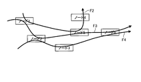
- FIG. 4 is a diagram illustrating a method of selecting INT information.
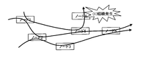
- FIG. 5 is a diagram illustrating a method of selecting INT information.
- FIG. 6 is a sequence diagram showing a processing procedure of the communication processing according to the first embodiment.
- FIG. 7 is a diagram showing an example of the configuration of the communication system in the second embodiment.
- FIG. 8 is a diagram showing an example of the data structure of the calculation result that the database (DB) shown in FIG. 7 has.
- FIG. DB database
- FIG. 9 is a diagram for explaining the flow of communication processing in the communication system shown in FIG. 7.
- FIG. 10 is a sequence diagram showing a processing procedure of communication processing according to the second embodiment.
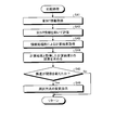
- FIG. 11 is a flowchart showing the processing procedure of the comparison processing shown in FIG.
- FIG. 12 is a diagram illustrating an example of a computer that realizes an information collection device, an information selection device, an information processing device, an NW device control device, and a comparison device by executing a program.
- FIG. 1 is a diagram showing an example of the configuration of a communication system in the first embodiment.
- the communication system according to the first embodiment is a system that manages the state of the network including the node 10 and the edge node 11 shown in FIG.
- the communication system according to the first embodiment includes an information collection device 20 (collection unit), an information selection device 30 (selection unit), an information processing device 40 (information processing unit), and a NW device control device 50 (control unit).
- the node 10 and the edge node 11 are transfer devices such as switches and routers.
- the node and the edge node 11 are connected by an optical fiber, a LAN (Local Area Network) cable or the like to form a network.
- the edge node 11 is a node located at the exit of the network.
- Each node 10 and edge node 11 are INT compatible devices, and use INT to notify the communication system of the status of their own devices.
- the state of the own device includes the presence/absence of a failure and the presence/absence of a congestion state.
- the node 10 and the edge node 11 add INT information to the packet passing through the own device.
- the INT information includes identification information of the own device and time stamp information indicating the transit time of the input port and the transit time of the output port of the self device.
- the INT information has been described as an example, but each node 10 and the edge node 11 add data different from the time stamp information to the packet passing through the own device by the same mechanism. Is also possible.
- FIG. 2 is a diagram showing an example of the data structure of INT information added to a packet.
- all the nodes existing in the network are INT compatible devices, and the number is M.
- time stamps at the ingress port and the egress port of each node 10 and the edge node 11 are added as INT information.
- the edge node 11 copies the INT information added to each packet and transfers it to the information collecting device 20. All the edge nodes 11 have this function because all the nodes existing at the edge of the network can be the termination points of any flow.
- the edge node 11 may transfer only the information of the INT header to the information collecting device 20, or may transfer the information including the payload to the information collecting device 20.
- the information collecting device 20 collects INT information from each node 10 and the edge node 11.
- the information collecting device 20 transfers the INT information collected from the edge node 11 to the information selecting device 30.
- the information collection device 20 centrally manages information from all edges.
- the management method of the collected information may be distributed or hierarchical.
- the information selection device 30 selects the INT information according to the selection condition from the INT information collected by the information collection device 20. For example, the information selection device 30 selects the INT information added to the packet that has passed through the specific node 10 and the edge node 11. The information selection device 30 transfers the selected INT information to the information processing device 40. When receiving the instruction to change the selection condition, the information selection device 30 changes the selection condition according to the instruction to change.
- the information processing device 40 is connected to the resource management device 60 that manages resources such as the remaining bandwidth of the network.
- the information processing device 40 performs a predetermined calculation process based on the INT information obtained from the information selection device 30 and the input information obtained by the resource management device 60 as necessary. For example, the information processing device 40 calculates the packet delay time based on the INT information.
- the device connected to the information processing device 40 is an example, and may be a device having a function other than resource management.
- the information processing device 40 outputs the calculation result to the NW device control device 50.
- the NW device control device 50 controls a network device (for example, a node) based on the calculation result of the information processing device 40.
- FIG. 3 is a diagram for explaining the flow of communication processing in the communication system shown in FIG. Note that the arrow F1 in FIG. 3 indicates a certain communication flow.
- a flow is a set of packets having the same 5-tupple (in/out port number, in/out IP address, protocol number).
- the information collection device 20 collects INT information from the edge node 11 (see (1) in FIG. 3). At this time, the information collection device 20 may collect the INT information of all the packets, or may collect the INT information of some of the packets. The information collecting device 20 transfers the collected INT information to the information selecting device 30. The information selection device 30 selects the INT information according to the selection condition, and transfers the selected INT information to the information processing device 40 (see (2) in FIG. 3).
- the information processing device 40 performs a predetermined calculation process based on the INT information transferred from the information selection device 30. At this time, the information processing device 40 may use other useful information (for example, resource management information) provided by the resource management device 60.
- resource management information for example, resource management information
- the information processing device 40 performs calculation for identifying the node 10 and the edge node 11 where resources are tight.
- the INT information includes time stamp information at the ingress port and the egress port of the node 10 and the edge node 11.
- the information processing apparatus 40 can use the time stamp information to calculate, for example, the delay time from when the network enters to when the network exits.
- the information processing apparatus 40 uses Expression (1) to calculate the delay time T d k from when the packet k, which is the target of delay time calculation, until the packet k enters the network and emerges.
- the information processing apparatus 40 can use the time stamp information to calculate the delay time of the packet k, which is the delay time calculation target, for each of the node 10 and the edge node 11. Specifically, the information processing apparatus 40, (2) using the formula, packet k is a calculation target delay time calculates the time T di k delayed by device i, increases the delay by a specific device You can check whether it is.
- the information processing device 40 outputs the calculation result to the NW device control device 50 (see (3) in FIG. 3).
- the NW device control device 50 controls the network devices (node 10 and edge node 11) based on the calculation result by the information processing device 40.
- the operator or the like may determine that the accuracy of the calculation result of the information processing device 40 is not sufficient.
- the operator or the like operates to instruct the information selection device 30 to change the INT information selection method (see (4) in FIG. 3 ).
- the information selection device 30 changes the INT information selection method to the instructed method.
- the situation in which the accuracy of the calculation result is poor is, for example, a situation in which the congestion occurrence point is identified by some external factor before the calculation by the information processing device 40.
- the information selection device 30 selects the INT information to be calculated from the collected INT information. Therefore, a method of selecting INT information by the information selection device 30 will be described. 4 and 5 are diagrams illustrating a method of selecting INT information.
- a selection method there is a method (first selection method) of selecting the INT information given by the devices (nodes) having the largest number of passing flows to some of the higher devices as a calculation target.
- first selection method there is a method (first selection method) of selecting the INT information given by the devices (nodes) having the largest number of passing flows to some of the higher devices as a calculation target.
- nodes 1, 2, 5, and 6 have a large number of passing flows. Therefore, when the first selection method is instructed, the information selection device 30 selects the INT information added to the packet in the nodes 1, 2, 5, and 6.
- a selection method there is a method (second selection method) of selecting the INT information added to the packet of the flow that has passed through a larger number of devices as the calculation target.
- the flow that covers a larger number of nodes is the flow F3. Therefore, when the second selection method is instructed, the information selection device 30 selects the INT information added to the packet of the flow F3.
- the information selection device 30 uses the second selection method. , And subsequent INT information selection processing is performed.
- the occurrence of delay or the location of delay may be identified by regular monitoring by SNMP or notification from the user, etc. before the discovery of occurrence of delay by the INT information and identification of the location of delay. In such a case, it is necessary to change the INT information selection method in the information selection device 30 in order to improve the accuracy of the calculation result.
- the operator who has grasped the external factor gives an instruction to change the selection method, and accordingly, the information selection device 30 changes the selection method to the instructed method. Then, the information selection device 30 selects the INT information by using the changed selection method, and as a result, the INT information input to the information processing device 40 is changed.
- the selection method is to limit the nodes 10 and the edge nodes 11 that confirm the INT information
- congestion may occur because the load on the other nodes 10 and the edge nodes 11 increases.
- the operator or the like instructs the change to the selection method that includes the faulty node 10 and the edge node 11 as the selection targets, so that the information selection device 30 passes through the faulty node 10 and the edge node 11.
- the INT information added to the selected packet can be selected.
- nodes 1, 2, 5, and 6 are the initial monitoring targets. Therefore, the information selection device 30 selects the INT information given by these nodes 1, 2, 5, 6 and transfers it as the input information of the information processing device 40.
- the information selection device 30 is instructed by the operation of the operator or the like to change the node to be monitored to the nodes 4, 1, 2, and 5 so as to include the node 4 in which congestion has occurred. Therefore, the information selection device 30 selects the INT information given by these nodes 4, 1, 2, 5 and transfers it as the input information of the information processing device 40.
- FIG. 6 is a sequence diagram showing a processing procedure of the communication processing according to the first embodiment.
- the edge node 11 located at the exit of the network copies the INT information added to each packet and transfers it to the information collecting device 20 (step S1).
- the information collecting device 20 collects the INT information transferred from the edge node 11 (step S2), and transfers the collected INT information to the information selecting device 30 (step S3).
- the information selection device 30 selects the INT information according to the selection condition from the INT information collected by the information collection device 20 (step S4).
- the information selection device 30 transfers the selected INT information to the information processing device 40 (step S5).
- the information processing device 40 acquires resource information from the resource management device 60 as needed (step S6). Then, the information processing device 40 performs a predetermined calculation process based on the INT information selected by the information selection device 30 and the resource information (step S7). The information processing device 40 outputs the calculation result to, for example, the NW device control device 50 (step S8). The NW device control device 50 controls the node 10 and the edge node 11 based on the calculation result by the information processing device 40 (steps S9 to S11).
- step S12 when an instruction to change the selection method is input to the input device by the operator (step S12) and the instruction to change the selection condition is notified (step S13), the information selection device 30 selects according to the change instruction. The conditions are changed (step S14).
- the INT information is collected from the edge node 11, the time stamp information according to the selection condition is selected from the collected INT information, and the selected INT information is used as the basis. Then, a predetermined calculation process is performed to control the NW device. That is, in the communication system according to the first embodiment, all the INT information collected from the edge node 11 is not used for the calculation process, but only the INT information selected from the collected INT information according to a predetermined selection method is used. Perform calculation processing using.
- the communication system according to the first embodiment it is not necessary to hold all the collected INT information for calculation processing. Further, according to the communication system according to the first embodiment, the calculation process is performed using a part of the selected INT information, so that the calculation time can be shortened as compared with the case where all the INT information is used. It is possible to improve efficiency.
- the communication system according to the first embodiment for example, when the accuracy of the calculation result of the information selection device 30 is poor, the INT information selection method is changed by an external operation in order to improve the accuracy of the calculation result. Is possible. Therefore, the communication system according to the first embodiment can flexibly change the INT information selection method according to the network condition, and can appropriately execute the calculation process of the information processing device 40.
- the first embodiment it is possible to appropriately and efficiently monitor the network status by selecting the INT information used for the calculation processing according to the network status.
- FIG. 7 is a diagram showing an example of the configuration of the communication system in the second embodiment.
- the information processing device 40 has a DB 41 that stores past calculation results.
- FIG. 8 is a diagram showing an example of the data structure of the calculation result held by the DB 41 shown in FIG.
- the information processing device 40 holds each calculation result as a past calculation result in association with the calculation start time and each input information. For example, for the serial number “2”, “2018/10/03” describes the calculation result “F” that started calculation using the information of input 1 “D” and input 2 “E”.
- the communication system according to the second embodiment further includes a comparison device 280 (comparing unit) as compared with the communication system according to the first embodiment.
- the comparison device 280 is connected to the information collection device 20, the information selection device 30, the information processing device 40, and the resource management device 60.
- the comparison device 280 performs a predetermined calculation process using all the INT information collected by the information collecting device 20, the resource information by the resource management device 60, and the like.
- the comparison device 280 includes the same calculation logic as the information processing device 40.
- the comparison device 280 obtains an error between the calculation result and the calculation result by the information processing device 40. Then, the comparison device 280 instructs the information selection device 30 to change the selection condition based on the comparison result between the obtained error and the preset threshold value. For example, the comparison device 280 instructs the information selection device 30 to change the selection method when the calculated error exceeds the threshold value.
- This threshold value is set in advance, for example, by an operation of an operator or the like. Further, this threshold can be changed by an operation of an operator or the like.
- the comparison device 280 instructs the information selection device 30 to change to the second selection method, obtains the INT information of the flow that has passed through a larger number of devices, and states the status to many devices. To be able to ask.
- FIG. 9 is a diagram for explaining the flow of communication processing in the communication system shown in FIG. 7.
- the information collecting device 20 collects the INT information from the edge node 11 (see (1) in FIG. 9), and the information selecting device 30 selects the INT information according to the selection condition. , And transfers the selected INT information to the information processing device 40 (see (2-1) in FIG. 9). Further, the information collecting device 20 transfers all the collected INT information to the comparing device 280 (see (2-2) in FIG. 9).
- the information processing device 40 performs a predetermined calculation process based on the INT information transferred from the information selection device 30 and outputs it to the comparison device 280 in addition to the NW device control device 50, as indicated by arrow Y1 ( See (3) of FIG. 9.
- the NW device control device 50 controls the network device based on the calculation result by the information processing device 40.
- the comparison device 280 performs the same calculation process as the information processing device 40 using all the INT information collected by the information collection device 20 (see (4) in FIG. 9). At this time, the comparison device 280 calculates, for example, a delay point without limiting the calculation time.
- the comparison device 280 acquires from the DB 41 of the information processing device 40 the same calculation start time input as the calculation start of its own device and the combination of the calculation results, and confirms the error in the calculation results. For example, when the comparison device 280 performs the calculation process of the calculation start time “2018/10/03”, the comparison device 280 inputs the table (see FIG. 8) stored in the DB 41 and the calculation start time “2018/10/03”. 1 "D", input 2 "E") and result "F” information is obtained (see row R2 in FIG. 8). Then, the comparison device 280 compares the calculation result of its own device with the obtained calculation result “F” to obtain an error.
- the comparison device 280 instructs the information selection device 30 to change the selection method (see (5) in FIG. 9). According to this instruction, the information selection device 30 changes the selection method.
- FIG. 10 is a sequence diagram showing a processing procedure of communication processing according to the second embodiment.
- Steps S21 to S23 shown in FIG. 10 are the same processes as steps S1 to S3 shown in FIG.
- the information collection device 20 transfers all the collected INT information to the comparison device 280 (step S24).
- Steps S25 to S32 shown in FIG. 10 are the same processes as steps S4 to S11 shown in FIG.
- the comparison device 280 acquires the calculation result by the information processing device 40 (step S33), compares the calculation result when all the INT information is used with the acquired calculation result by the information processing device 40, and selects the information selection device 30.
- the comparison process for instructing the change of the selection method in step S34 is performed (step S34).
- the comparison device 280 instructs the information selection device 30 to change the selection method of the INT information according to the result of the comparison process (step S35), and the information selection device 30 changes the selection method according to the change instruction. Yes (step S36).
- FIG. 11 is a flowchart showing the processing procedure of the comparison processing shown in FIG.
- the comparison device 280 acquires all INT division methods collected by the information collection device 20 (step S41).
- the comparison device 280 performs a predetermined calculation process using all the INT information (step S42). Then, the calculation result of the information processing device 40 is acquired (step S43), and the error between the calculation result of the own device and the calculation result acquired from the information processing device 40 is obtained (step S44).
- the comparison device 280 determines whether or not the calculated error exceeds the threshold value (step S45).
- the comparison device 280 determines that the calculated error exceeds the threshold value (step S45: Yes)
- the comparison device 280 notifies the information selection device 30 of a selection method change instruction (step S46), and ends the comparison process.
- the comparison device 280 determines that the calculated error does not exceed the threshold value (step S45: No)
- the comparison process ends.
- the communication system according to the second embodiment further includes the comparison device 280, and automatically changes the selection method inside the communication system. Therefore, as compared with the first embodiment, the INT information selection method can be changed before the instruction by the operator or the like, and the accuracy of the calculation processing of information processing can be maintained.
- the comparison device 280 may select the selection method instructing the information selection device 30 according to the degree to which the error between the calculation result of the own device and the calculation result of the information processing device 40 exceeds the threshold value. For example, when the calculated error exceeds the threshold value and the difference between the calculated error and the threshold value is equal to or more than a predetermined value, the comparison device 280 causes the information selection device 30 to change to the second selection method. Give instructions. On the other hand, when the calculated error exceeds the threshold value and the difference between the calculated error and the threshold value is less than the predetermined value, the comparison device 280 causes the information selection device 30 to select a second method different from the second selection method. Instruct to change to the selection method of No. 3.
- each component of each device shown in the drawings is functionally conceptual, and does not necessarily have to be physically configured as shown. That is, the specific form of distribution/integration of each device is not limited to that shown in the figure, and all or part of the device may be functionally or physically distributed/arranged in arbitrary units according to various loads and usage conditions. It can be integrated and configured. Furthermore, each processing function performed by each device is realized in whole or in part by a CPU (Central Processing Unit) and a program that is analyzed and executed by the CPU, or a hardware by a wired logic. Can be realized as.
- a CPU Central Processing Unit
- FIG. 12 is a diagram illustrating an example of a computer in which the information collection device 20, the information selection device 30, the information processing device 40, the NW device control device 50, and the comparison device 280 are realized by executing the program.
- the computer 1000 has, for example, a memory 1010 and a CPU 1020.
- the computer 1000 also has a hard disk drive interface 1030, a disk drive interface 1040, a serial port interface 1050, a video adapter 1060, and a network interface 1070. These units are connected by a bus 1080.
- the memory 1010 includes a ROM (Read Only Memory) 1011 and a RAM (Random Access Memory) 1012.
- the ROM 1011 stores, for example, a boot program such as BIOS (Basic Input Output System).
- BIOS Basic Input Output System
- the hard disk drive interface 1030 is connected to the hard disk drive 1090.
- the disk drive interface 1040 is connected to the disk drive 1100.
- a removable storage medium such as a magnetic disk or an optical disk is inserted into the disk drive 1100.
- the serial port interface 1050 is connected to, for example, a mouse 1110 and a keyboard 1120.
- the video adapter 1060 is connected to the display 1130, for example.
- the hard disk drive 1090 stores, for example, an OS (Operating System) 1091, an application program 1092, a program module 1093, and program data 1094. That is, the program defining each process of the information collecting device 20, the information selecting device 30, the information processing device 40, the NW device control device 50, and the comparing device 280 is implemented as a program module 1093 in which a code executable by a computer is described. To be done.
- the program module 1093 is stored in the hard disk drive 1090, for example.
- the hard disk drive 1090 stores a program module 1093 for executing the same processing as the functional configuration of the information collecting device 20, the information selecting device 30, the information processing device 40, the NW device control device 50, and the comparison device 280. ..
- the hard disk drive 1090 may be replaced by an SSD (Solid State Drive).
- the setting data used in the processing of the above-described embodiment is stored as program data 1094 in, for example, the memory 1010 or the hard disk drive 1090. Then, the CPU 1020 reads out the program module 1093 or the program data 1094 stored in the memory 1010 or the hard disk drive 1090 to the RAM 1012 as necessary and executes the program module 1093 or the program data 1094.
- the program module 1093 and the program data 1094 are not limited to being stored in the hard disk drive 1090, and may be stored in, for example, a removable storage medium and read by the CPU 1020 via the disk drive 1100 or the like. Alternatively, the program module 1093 and the program data 1094 may be stored in another computer connected via a network (LAN, WAN (Wide Area Network), etc.). Then, the program module 1093 and the program data 1094 may be read by the CPU 1020 from another computer via the network interface 1070.
- LAN Local Area Network
- WAN Wide Area Network
Landscapes
- Engineering & Computer Science (AREA)
- Computer Networks & Wireless Communication (AREA)
- Signal Processing (AREA)
- Environmental & Geological Engineering (AREA)
- Health & Medical Sciences (AREA)
- Cardiology (AREA)
- General Health & Medical Sciences (AREA)
- Data Exchanges In Wide-Area Networks (AREA)
Abstract
通信システムは、エッジノード(11)から、パケットに付与された各ノード(10)の入力ポートの経由時間と出力ポートの経由時間とを示すINT情報を収集する情報収集装置(20)と、収集されたタイムスタンプ情報のうち、選択条件に応じたタイムスタンプ情報を選択する情報選択装置(30)と、選択されたタイムススタンプ情報を基に所定の計算処理を行う情報処理装置(40)と、情報処理装置(40)による計算結果を基にネットワーク機器を制御するNW機器制御装置(50)と、を有する。
Description
本発明は、通信システム及び通信方法に関する。
ネットワーク管理のために、ネットワーク状態を監視する方法が提案されている。例えば、従来からよく用いられている方法として、SNMP(Simple Network Management Protocol)がある(非特許文献1参照)。
このSNMPは、管理及び監視を行うSNMPサーバが、監視下の装置に、該装置の状態情報の送信リクエストを送り、監視下の装置が自装置の状態をSNMPサーバにレスポンスする。この監視下の装置は、SNMPサーバによるリクエストがある度にSNMPサーバにレスポンスを行う。このため、SNMPでは、SNMPサーバの監視下の装置の状態しか把握できない。具体的には、SNMPでは、パケットロスが発生したことはでは判別できるものの、いずれのユーザのいずれのパケットに影響が出たか、までを特定することはできない。
また、他の方法として、Streaming Telemetryがある(非特許文献2参照)。Streaming Telemetryでは、監視下の装置に、予め、所定時間毎に状態通知を送信するように設定を行う。このため、監視下の各装置は、レスポンス相当の内容を定期的に送信する。この結果、Streaming Telemetryでは、SNMPと比して、各装置の負荷が軽減できる。
これに対し、INT(In-band Network Telemetry)は、上記の方法が用いた状態通知専用のメッセージの送信に変えて、監視下の各装置が、ユーザが送信するパケットデータ自体に専用のヘッダを埋め込む処理を行う(例えば、非特許文献3参照)。
INTでは、パケット単位で情報を付与するため、上記のSNMPやStreaming Telemetryと異なり、パケットロスや遅延が発生した場合に、どのパケットが影響を受けたかを特定することが可能である。そして、サーバ及び監視下の装置が、リクエスト及びレスポンスの情報を個別に作成するSNMPと比して、INTでは、サーバ及び監視下の装置の負担は軽減できるものと考えられる。このように、INTは、従来のSNMP、Streaming Telemetryと状態情報の通知方法が異なり、さらに、監視対象の粒度を小さくすることができる。
A Simple Network Management Protocol,[online],[平成30年12月10日検索],インターネット<URL:https://tools.ietf.org/html/rfc1157>
テレメトリデータのストリーミング, [online],[平成30年12月10日検索],インターネット<URL:https://www.cisco.com/c/ja_jp/td/docs/rt/wanaggregationinternetedgert/nwconvergencesystem5000/cg/011/Telemetry-Config-Guide/Telemetry-Config-Guide_chapter_00.pdf>
In‐band Network Telemetry (INT), [online]、[平成30年12月10日検索],インターネット<https://p4.org/assets/INT-current-spec.pdf>
しかしながら、INTを用いた場合、SNMP等を用いる場合よりも装置の状態及び通信品質の状況を詳細に監視できる反面、取得する情報量が膨大になる。この結果、取得する全INT情報を用いた場合、膨大な情報量を保持することが必要になるという問題や、情報処理に要する計算時間が長大になるという問題が生じ、ネットワークの状態監視を適切かつ効率的に実行することが難しい場合があった。
本発明は、上記に鑑みてなされたものであって、ネットワークの状態監視を適切かつ効率的に実行することができる通信システム及び通信方法を提供することを目的とする。
上述した課題を解決し、目的を達成するために、本発明に係る通信システムは、自装置を経由するパケットに対して自装置の識別情報とともに入力ポートの経由時間と出力ポートの経由時間とを示すタイムスタンプ情報を付与する転送装置から、タイムスタンプ情報を収集する収集部と、収集部によって収集されたタイムスタンプ情報のうち、選択条件に応じたタイムスタンプ情報を選択する選択部と、選択部によって選択されたタイムススタンプ情報を基に所定の計算処理を行う処理部と、処理部による計算結果を基にネットワーク機器を制御する制御部と、を有することを特徴とする。
本発明によれば、ネットワークの状態監視を適切かつ効率的に実行することができる。
以下、図面を参照して、本発明の一実施形態を詳細に説明する。なお、この実施の形態により本発明が限定されるものではない。また、図面の記載において、同一部分には同一の符号を付して示している。
[実施の形態1]
本発明の実施の形態1について説明する。図1は、実施の形態1における通信システムの構成の一例を示す図である。
本発明の実施の形態1について説明する。図1は、実施の形態1における通信システムの構成の一例を示す図である。
実施の形態1に係る通信システムは、図1に示すノード10及びエッジノード11を有するネットワークの状態を管理するシステムである。実施の形態1に係る通信システムは、情報収集装置20(収集部)、情報選択装置30(選択部)、情報処理装置40(情報処理部)及びNW機器制御装置50(制御部)を有する。
ノード10及びエッジノード11は、スイッチやルータ等の転送装置である。ノード及びエッジノード11は、光ファイバやLAN(Local Area Network)ケーブル等で接続され、ネットワークを構成する。エッジノード11は、ネットワークの出口に位置するノードである。
各ノード10及びエッジノード11は、INT対応装置であり、自装置の状態を通信システムに通知するために、INTを利用している。自装置の状態として、故障の有無、輻輳状態の有無等がある。ノード10及びエッジノード11は、自装置を経由するパケットに対して、INT情報を付与する。INT情報は、自装置の識別情報とともに、自装置の入力ポートの経由時間と出力ポートの経由時間とを示すタイムスタンプ情報を含む。なお、実施の形態1では、INT情報を例に説明したが、各ノード10及びエッジノード11は、同様の仕組みで、タイムスタンプ情報とは異なるデータを、自装置を経由したパケットに付与することも可能である。
図2は、パケットに付与されたINT情報のデータ構成の一例を示す図である。ここでは、ネットワーク内に存在するノード数は、全てINT対応装置であると仮定し、その数をMとする。図2に示すように、各ノード10及びエッジノード11から、INT情報として、例えば、各ノード10及びエッジノード11のingressポートとegressポートとにおけるタイムスタンプが付与される。
エッジノード11は、各パケットに付与されたINT情報をコピーし、情報収集装置20に転送する。ネットワークのエッジに存在する全てのノードは、いずれかのフローの終端点となり得るため、全てのエッジノード11は、この機能を有する。なお、エッジノード11は、INTヘッダの情報のみを情報収集装置20に転送してもよいし、ペイロードを含む情報を情報収集装置20に転送してもよい。
情報収集装置20は、各ノード10及びエッジノード11から、INT情報を収集する。情報収集装置20は、エッジノード11から収集したINT情報を情報選択装置30へ転送する。図1の例では、情報収集装置20が、全てのエッジからの情報を集中的に管理しているものとする。なお、収集した情報の管理方法は、分散的または階層的であってもよい。
情報選択装置30は、情報収集装置20によって収集されたINT情報のうち、選択条件に応じたINT情報を選択する。例えば、情報選択装置30は、特定のノード10及びエッジノード11を経由したパケットに付与されたINT情報を選択する。情報選択装置30は、選択したINT情報を、情報処理装置40へ転送する。情報選択装置30は、選択条件の変更指示を受けた場合に、この変更指示に従って選択条件を変更する。
情報処理装置40は、ネットワークの残帯域等のリソースを管理するリソース管理装置60と接続する。情報処理装置40は、情報選択装置30から得たINT情報と、必要に応じて取得したリソース管理装置60による入力情報とを基に、所定の計算処理を行う。例えば、情報処理装置40は、INT情報を基に、パケットの遅延時間を計算する。なお、情報処理装置40が接続する装置は、一例であり、リソース管理以外の他の機能を有する装置であってもよい。情報処理装置40は、計算結果を、NW機器制御装置50に出力する。
NW機器制御装置50は、情報処理装置40による計算結果を基に、ネットワーク機器(例えば、ノード)を制御する。
[通信処理の流れ]
次に、図1に示す通信システムにおける通信処理の流れについて説明する。図3は、図1に示す通信システムにおける通信処理の流れについて説明する図である。なお、図3における矢印F1は、ある通信のフローを示す。ここで、フローとは、5-tupple(in/outのポート番号、in/outのIPアドレス、プロトコル番号)が等しいパケットの集合である。
次に、図1に示す通信システムにおける通信処理の流れについて説明する。図3は、図1に示す通信システムにおける通信処理の流れについて説明する図である。なお、図3における矢印F1は、ある通信のフローを示す。ここで、フローとは、5-tupple(in/outのポート番号、in/outのIPアドレス、プロトコル番号)が等しいパケットの集合である。
図3に示すように、情報収集装置20は、エッジノード11から、INT情報の収集を行う(図3の(1)参照)。この際、情報収集装置20は、全パケットのINT情報を収集してもよく、また、一部のパケットのINT情報を収集してもよい。情報収集装置20は、収集したINT情報を情報選択装置30に転送する。情報選択装置30は、選択条件に応じたINT情報を選択し、選択したINT情報を情報処理装置40に転送する(図3の(2)参照)。
情報処理装置40は、情報選択装置30から転送されたINT情報を基に、所定の計算処理を行う。この際、情報処理装置40は、リソース管理装置60によるその他の有用な情報(例えば、リソース管理情報)を用いてもよい。
例えば、情報処理装置40は、リソースが逼迫しているノード10及びエッジノード11を特定するための計算を行う。図2に示すように、INT情報は、ノード10及びエッジノード11のingressポートとegressポートにおけるタイムスタンプ情報を含む。情報処理装置40は、これらのタイムスタンプ情報に用いて、例えば、ネットワークに入ってから出てくるまでの間の遅延時間を計算することが可能である。具体的には、情報処理装置40は、(1)式を用いて、遅延時間の計算対象であるパケットkがネットワークに入ってから出てくるまでの遅延時間Td
kを計算する。

また、情報処理装置40は、これらのタイムスタンプ情報に用いて、ノード10及びエッジノード11ごとに、遅延時間の計算対象であるパケットkが遅延した時間を計算することができる。具体的には、情報処理装置40は、(2)式を用いて、遅延時間の計算対象であるパケットkが装置iで遅延した時間Tdi
kを計算し、特定の装置だけ遅延が大きくなっているかどうかを確認することができる。

続いて、情報処理装置40は、計算結果を、NW機器制御装置50に出力する(図3の(3)参照)。NW機器制御装置50は、情報処理装置40による計算結果を基に、ネットワーク機器(ノード10及びエッジノード11)を制御する。
さらに、オペレータ等が、情報処理装置40の計算結果の精度が十分ではないと判断する場合がある。この場合には、オペレータ等による操作によって、情報選択装置30におけるINT情報の選択方法の変更が指示される(図3の(4)参照)。情報選択装置30は、選択方法の変更指示を受けると、INT情報の選択方法を、指示された方法に変更する。ここで、計算結果の精度が悪い状況とは、例えば、情報処理装置40による計算よりも先に、何らかの外的要因によって輻輳発生箇所が判明するような状況である。
[INT情報の選択方法]
ネットワーク内の輻輳を検知する上で、エッジノード11が全てのINT情報を情報収集装置20に転送し、これら全てのINT情報を情報処理装置40における計算対象とした場合には、膨大な情報量を保持することが必要になり、情報処理に要する計算時間が実用的な時間で完了できなくなる。本実施の形態1では、情報選択装置30が、収集されたINT情報から、計算対象のINT情報を選択している。そこで、この情報選択装置30によるINT情報の選択方法について説明する。図4及び図5は、INT情報の選択方法を説明する図である。
ネットワーク内の輻輳を検知する上で、エッジノード11が全てのINT情報を情報収集装置20に転送し、これら全てのINT情報を情報処理装置40における計算対象とした場合には、膨大な情報量を保持することが必要になり、情報処理に要する計算時間が実用的な時間で完了できなくなる。本実施の形態1では、情報選択装置30が、収集されたINT情報から、計算対象のINT情報を選択している。そこで、この情報選択装置30によるINT情報の選択方法について説明する。図4及び図5は、INT情報の選択方法を説明する図である。
例えば、選択方法として、経由するフローが最も多い装置(ノード)から上位いくつかまでの装置で付与されたINT情報を計算対象として選択する方法(第1の選択方法)がある。図4の例の場合、経由するフロー数の多いノードは、ノード1,2,5,6である。このため、情報選択装置30は、第1の選択方法が指示された場合、ノード1,2,5,6においてパケットに付与されたINT情報を選択する。
また、選択方法として、より数の多い装置を経由したフローのパケットに付与されたINT情報を計算対象として選択する方法(第2の選択方法)がある。図4のフローF2~F4のうち、より数の多いノードを網羅するフローは、フローF3である。このため、情報選択装置30は、第2の選択方法が指示された場合、フローF3のパケットに付与されたINT情報を選択する。
情報選択装置30に第1の選択方法が設定されており、オペレータ等によって、第2の選択方法への変更が指示された場合には、情報選択装置30は、第2の選択方法を用いて、以降のINT情報選択処理を行う。
ここで、第1及び第2の選択方法を用いて、計算対象のINT情報を制限して輻輳箇所を算出しようとすると、全てのINT情報を用いる場合と比べて計算結果に誤差が生じることが考えられる。
例えば、INT情報による遅延発生の発見や遅延箇所の特定よりも前に、SNMPによる定期監視やユーザからの申告等により、遅延の発生や遅延箇所が判明してしまうことが考えられる。このような場合、計算結果の精度を上げるために、情報選択装置30におけるINT情報の選択方法を変更する必要がある。
この場合、外的要因を把握したオペレータは、選択方法の変更指示を行い、これにともない、情報選択装置30は、指示された方法に、選択方法を変更する。そして、情報選択装置30は、変更した選択方法を用いてINT情報を選択し、この結果、情報処理装置40に入力するINT情報が変更される。
例えば、INT情報を確認するノード10及びエッジノード11を限定する選択方法であった場合に、それ以外のノード10及びエッジノード11の負荷が高くなる等の理由で輻輳を発生させていることが推定より先に判明した場合を例に説明する。この場合、オペレータ等は、故障しているノード10及びエッジノード11を選択対象に含む選択方法に変更を指示することによって、情報選択装置30が、故障しているノード10及びエッジノード11を経由したパケットに付与されたINT情報を選択できるようにする。
具体的には、フロー数の多いノードを上位4つだけ監視対象として選択する選択方法が適用されている場合を例に説明する。図5の例では、ノード1,2,5,6が初期の監視対象となる。このため、情報選択装置30は、これらのノード1,2,5,6で付与されたINT情報を選択し、情報処理装置40の入力情報として転送する。
ここで、ノード4で輻輳が発生していることが判明した場合(図5の(1)参照)について説明する。この場合には、オペレータ等の操作によって、輻輳が発生したノード4を含むように、監視対象のノードを、ノード4、1,2,5に変更する指示が情報選択装置30に通知される。このため、情報選択装置30は、これらのノード4,1,2,5で付与されたINT情報を選択し、情報処理装置40の入力情報として転送する。
[通信処理の処理手順]
次に、実施の形態1に係る通信処理の処理手順について説明する。図6は、実施の形態1に係る通信処理の処理手順を示すシーケンス図である。
次に、実施の形態1に係る通信処理の処理手順について説明する。図6は、実施の形態1に係る通信処理の処理手順を示すシーケンス図である。
図6に示すように、ネットワークの出口に位置するエッジノード11が、各パケットに付与されたINT情報をコピーし、情報収集装置20に転送する(ステップS1)。通信システムでは、情報収集装置20は、エッジノード11から転送されたINT情報を収集し(ステップS2)、収集したINT情報を情報選択装置30へ転送する(ステップS3)。
情報選択装置30は、情報収集装置20によって収集されたINT情報のうち、選択条件に応じたINT情報を選択する(ステップS4)。情報選択装置30は、選択したINT情報を、情報処理装置40へ転送する(ステップS5)。
情報処理装置40は、必要に応じてリソース管理装置60からリソース情報を取得する(ステップS6)。そして、情報処理装置40は、情報選択装置30による選択後のINT情報と、リソース情報とを基に、所定の計算処理を行う(ステップS7)。情報処理装置40は、計算結果を、例えば、NW機器制御装置50に出力する(ステップS8)。NW機器制御装置50は、情報処理装置40による計算結果を基に、ノード10及びエッジノード11を制御する(ステップS9~S11)。
そして、入力装置に、オペレータ等による選択方法の変更指示が入力され(ステップS12)、選択条件の変更指示が通知された場合には(ステップS13)、情報選択装置30は、この変更指示に従って選択条件を変更する(ステップS14)。
[実施の形態1の効果]
このように、本実施の形態1に係る通信システムでは、エッジノード11からINT情報を収集し、収集したINT情報のうち、選択条件に応じたタイムスタンプ情報を選択し、選択したINT情報を基に所定の計算処理を行って、NW機器を制御する。すなわち、本実施の形態1に係る通信システムでは、エッジノード11から収集した全てのINT情報を計算処理に用いるのではなく、収集したINT情報から所定の選択方法にしたがって選択されたINT情報のみを用いて計算処理を行う。
このように、本実施の形態1に係る通信システムでは、エッジノード11からINT情報を収集し、収集したINT情報のうち、選択条件に応じたタイムスタンプ情報を選択し、選択したINT情報を基に所定の計算処理を行って、NW機器を制御する。すなわち、本実施の形態1に係る通信システムでは、エッジノード11から収集した全てのINT情報を計算処理に用いるのではなく、収集したINT情報から所定の選択方法にしたがって選択されたINT情報のみを用いて計算処理を行う。
したがって、本実施の形態1に係る通信システムによれば、収集したINT情報の全てを、計算処理のために保持する必要もない。また、本実施の形態1に係る通信システムによれば、選択された一部のINT情報を用いて計算処理を行うため、全INT情報を用いた場合と比して、計算時間を短縮することができ、効率化を図ることができる。
また、実施の形態1にかかる通信システムでは、例えば、情報選択装置30の計算結果の精度が悪い場合など、計算結果の精度を上げるために、外部からの操作によって、INT情報の選択方法の変更が可能である。したがって、実施の形態1に係る通信システムは、ネットワークの状況に応じて、INT情報の選択方法を柔軟に変更でき、情報処理装置40の計算処理を適切に実行することができる。
このため、本実施の形態1によれば、計算処理に用いるINT情報をネットワーク状況に応じて選択することによって、ネットワークの状態監視を適切かつ効率的に実行することができる。
[実施の形態2]
次に、実施の形態2について説明する。図7は、実施の形態2における通信システムの構成の一例を示す図である。
次に、実施の形態2について説明する。図7は、実施の形態2における通信システムの構成の一例を示す図である。
図7に示すように、実施の形態2に係る通信システムでは、情報処理装置40が、過去の計算結果を記憶するDB41を有する。図8は、図7に示すDB41が有する計算結果のデータ構成の一例を示す図である。図8に示すように、情報処理装置40は、過去の計算結果として、計算開始時間及び各入力情報とに対応付けて各計算結果を保持する。例えば、通番「2」は、「2018/10/03」に、入力1「D」、入力2「E」の情報を用いて計算を開始した計算結果「F」が記載されている。
そして、図7に示すように、実施の形態2に係る通信システムは、実施の形態1に係る通信システムと比して、さらに、比較装置280(比較部)を有する。比較装置280は、情報収集装置20、情報選択装置30、情報処理装置40及びリソース管理装置60と接続する。
比較装置280は、情報収集装置20によって収集された全てのINT情報、及び、リソース管理装置60によるリソース情報等を用いて、所定の計算処理を行う。比較装置280は、情報処理装置40と同じ計算ロジックを内包する。
比較装置280は、該計算結果及び情報処理装置40による計算結果の誤差を求める。そして、比較装置280は、求めた誤差と、予め設定された閾値との比較結果を基に、選択条件の変更を情報選択装置30に指示する。例えば、比較装置280は、求めた誤差が閾値を超えた場合に、情報選択装置30に選択方法の変更を指示する。この閾値は、例えば、オペレータ等の操作によって予め設定される。また、この閾値は、オペレータ等の操作によって、変更も可能である。
例えば、情報選択装置30に第1の選択方法が適用されていた場合に、求めた誤差が閾値を超えた場合について説明する。この場合、比較装置280は、情報選択装置30に、第2の選択方法への変更を指示し、より数の多い装置を経由したフローのINT情報を取得して、多くの装置に対して状況を求めることができるようにする。
[通信処理の流れ]
次に、図7に示す通信システムにおける通信処理の流れについて説明する。図9は、図7に示す通信システムにおける通信処理の流れについて説明する図である。
次に、図7に示す通信システムにおける通信処理の流れについて説明する。図9は、図7に示す通信システムにおける通信処理の流れについて説明する図である。
図9に示すように、情報収集装置20は、エッジノード11から、INT情報の収集を行い(図9の(1)参照)、情報選択装置30は、選択条件に応じたINT情報を選択し、選択したINT情報を情報処理装置40に転送する(図9の(2-1)参照)。また、情報収集装置20は、収集した全てのINT情報を、比較装置280に転送する(図9の(2-2)参照)。
情報処理装置40は、情報選択装置30から転送されたINT情報を基に、所定の計算処理を行い、NW機器制御装置50に加え、矢印Y1に示すように、比較装置280にも出力する(図9の(3)参照)。NW機器制御装置50は、情報処理装置40による計算結果を基に、ネットワーク機器を制御する。
そして、比較装置280は、情報収集装置20が収集した全INT情報を用いて、情報処理装置40と同じ計算処理を実施する(図9の(4)参照)。この際、比較装置280は、比較装置280は、計算時間を限らずに、例えば遅延箇所を算出する。
続いて、比較装置280は、情報処理装置40のDB41から、自装置の計算開始と同じ計算開始時間の入力と計算結果の組合せとを取得し、計算結果の誤差を確認する。例えば、比較装置280は、計算開始時間「2018/10/03」の計算処理を実施した場合、DB41が記憶するテーブル(図8参照)、計算開始時間「2018/10/03」の入力(入力1「D」、入力2「E」)及び結果「F」の情報を取得する(図8の行R2参照)。そして、比較装置280は、自装置の計算結果と、取得した計算結果「F」とを比較し、誤差を求める。
そして、比較装置280は、求めた誤差が閾値を超過した場合には、情報選択装置30に、選択方法の変更を指示する(図9の(5)参照)。この指示に従い、情報選択装置30は、選択方法を変更する。
[通信処理の処理手順]
次に、実施の形態1に係る通信処理の処理手順について説明する。図10は、実施の形態2に係る通信処理の処理手順を示すシーケンス図である。
次に、実施の形態1に係る通信処理の処理手順について説明する。図10は、実施の形態2に係る通信処理の処理手順を示すシーケンス図である。
図10に示すステップS21~S23は、図6に示すステップS1~S3と同じ処理である。実施の形態2では、情報収集装置20は、収集した全てのINT情報を、比較装置280へ転送する(ステップS24)。図10に示すステップS25~S32は、図6に示すステップS4~S11と同じ処理である。
比較装置280は、情報処理装置40による計算結果を取得し(ステップS33)、全てのINT情報を用いた場合の計算結果と、取得した情報処理装置40による計算結果を比較して情報選択装置30における選択方法の変更を指示する比較処理を行う(ステップS34)。そして、比較装置280は、比較処理の結果に応じて、情報選択装置30に、INT情報の選択方法の変更を指示し(ステップS35)、情報選択装置30は、この変更指示に従って選択方法を変更する(ステップS36)。
[比較処理の処理手順]
次に、比較処理(ステップS34)の処理手順について説明する。図11は、図10に示す比較処理の処理手順を示すフローチャートである。
次に、比較処理(ステップS34)の処理手順について説明する。図11は、図10に示す比較処理の処理手順を示すフローチャートである。
図11に示すように、比較装置280は、情報収集装置20が収集した全INT除法を取得する(ステップS41)。比較装置280は、全INT情報を用いて所定の計算処理を行う(ステップS42)。そして、情報処理装置40による計算結果を取得して(ステップS43)、自装置で計算した結果と、情報処理装置40から取得した計算結果との誤差を求める(ステップS44)。
そして、比較装置280は、求めた誤差が閾値を超えたか否かを判定する(ステップS45)。比較装置280は、求めた誤差が閾値を超えたと判定した場合(ステップS45:Yes)、情報選択装置30に選択方法の変更指示を通知し(ステップS46)、比較処理を終了する。一方、比較装置280は、求めた誤差が閾値を超えていないと判定した場合(ステップS45:No)、比較処理を終了する。
[実施の形態2の効果]
このように、実施の形態2に係る通信システムは、比較装置280をさらに設け、選択方法の変更を、通信システム内部で自動的に実行する。このため、実施の形態1と比して、オペレータ等による指示の前に、INT情報の選択方法を変更することができ、情報処理の計算処理の精度の維持を図ることができる。
このように、実施の形態2に係る通信システムは、比較装置280をさらに設け、選択方法の変更を、通信システム内部で自動的に実行する。このため、実施の形態1と比して、オペレータ等による指示の前に、INT情報の選択方法を変更することができ、情報処理の計算処理の精度の維持を図ることができる。
なお、比較装置280は、自装置による計算結果及び情報処理装置40による計算結果の誤差が、閾値を超えた度合いに応じて、情報選択装置30に指示する選択方法を選択してもよい。例えば、比較装置280は、求めた誤差が閾値を超えており、求めた誤差と閾値との差が所定値以上である場合には、情報選択装置30に、第2の選択方法への変更を指示する。一方、比較装置280は、求めた誤差が閾値を超えており、求めた誤差と閾値との差が所定値未満である場合には、情報選択装置30に、第2の選択方法とは異なる第3の選択方法への変更を指示する。
[システム構成等]
図示した各装置の各構成要素は機能概念的なものであり、必ずしも物理的に図示の如く構成されていることを要しない。すなわち、各装置の分散・統合の具体的形態は図示のものに限られず、その全部又は一部を、各種の負荷や使用状況等に応じて、任意の単位で機能的又は物理的に分散・統合して構成することができる。さらに、各装置にて行なわれる各処理機能は、その全部又は任意の一部が、CPU(Central Processing Unit)及び当該CPUにて解析実行されるプログラムにて実現され、あるいは、ワイヤードロジックによるハードウェアとして実現され得る。
図示した各装置の各構成要素は機能概念的なものであり、必ずしも物理的に図示の如く構成されていることを要しない。すなわち、各装置の分散・統合の具体的形態は図示のものに限られず、その全部又は一部を、各種の負荷や使用状況等に応じて、任意の単位で機能的又は物理的に分散・統合して構成することができる。さらに、各装置にて行なわれる各処理機能は、その全部又は任意の一部が、CPU(Central Processing Unit)及び当該CPUにて解析実行されるプログラムにて実現され、あるいは、ワイヤードロジックによるハードウェアとして実現され得る。
また、本実施形態において説明した各処理のうち、自動的に行われるものとして説明した処理の全部又は一部を手動的に行なうこともでき、あるいは、手動的に行なわれるものとして説明した処理の全部又は一部を公知の方法で自動的に行なうこともできる。この他、上記文書中や図面中で示した処理手順、制御手順、具体的名称、各種のデータやパラメータを含む情報については、特記する場合を除いて任意に変更することができる。
[プログラム]
図12は、プログラムが実行されることにより、情報収集装置20、情報選択装置30、情報処理装置40、NW機器制御装置50及び比較装置280が実現されるコンピュータの一例を示す図である。コンピュータ1000は、例えば、メモリ1010、CPU1020を有する。また、コンピュータ1000は、ハードディスクドライブインタフェース1030、ディスクドライブインタフェース1040、シリアルポートインタフェース1050、ビデオアダプタ1060、ネットワークインタフェース1070を有する。これらの各部は、バス1080によって接続される。
図12は、プログラムが実行されることにより、情報収集装置20、情報選択装置30、情報処理装置40、NW機器制御装置50及び比較装置280が実現されるコンピュータの一例を示す図である。コンピュータ1000は、例えば、メモリ1010、CPU1020を有する。また、コンピュータ1000は、ハードディスクドライブインタフェース1030、ディスクドライブインタフェース1040、シリアルポートインタフェース1050、ビデオアダプタ1060、ネットワークインタフェース1070を有する。これらの各部は、バス1080によって接続される。
メモリ1010は、ROM(Read Only Memory)1011及びRAM(Random Access Memory)1012を含む。ROM1011は、例えば、BIOS(Basic Input Output System)等のブートプログラムを記憶する。ハードディスクドライブインタフェース1030は、ハードディスクドライブ1090に接続される。ディスクドライブインタフェース1040は、ディスクドライブ1100に接続される。例えば磁気ディスクや光ディスク等の着脱可能な記憶媒体が、ディスクドライブ1100に挿入される。シリアルポートインタフェース1050は、例えばマウス1110、キーボード1120に接続される。ビデオアダプタ1060は、例えばディスプレイ1130に接続される。
ハードディスクドライブ1090は、例えば、OS(Operating System)1091、アプリケーションプログラム1092、プログラムモジュール1093、プログラムデータ1094を記憶する。すなわち、情報収集装置20、情報選択装置30、情報処理装置40、NW機器制御装置50及び比較装置280の各処理を規定するプログラムは、コンピュータにより実行可能なコードが記述されたプログラムモジュール1093として実装される。プログラムモジュール1093は、例えばハードディスクドライブ1090に記憶される。例えば、情報収集装置20、情報選択装置30、情報処理装置40、NW機器制御装置50及び比較装置280における機能構成と同様の処理を実行するためのプログラムモジュール1093が、ハードディスクドライブ1090に記憶される。なお、ハードディスクドライブ1090は、SSD(Solid State Drive)により代替されてもよい。
また、上述した実施形態の処理で用いられる設定データは、プログラムデータ1094として、例えばメモリ1010やハードディスクドライブ1090に記憶される。そして、CPU1020が、メモリ1010やハードディスクドライブ1090に記憶されたプログラムモジュール1093やプログラムデータ1094を必要に応じてRAM1012に読み出して実行する。
なお、プログラムモジュール1093やプログラムデータ1094は、ハードディスクドライブ1090に記憶される場合に限らず、例えば着脱可能な記憶媒体に記憶され、ディスクドライブ1100等を介してCPU1020によって読み出されてもよい。あるいは、プログラムモジュール1093及びプログラムデータ1094は、ネットワーク(LAN、WAN(Wide Area Network)等)を介して接続された他のコンピュータに記憶されてもよい。そして、プログラムモジュール1093及びプログラムデータ1094は、他のコンピュータから、ネットワークインタフェース1070を介してCPU1020によって読み出されてもよい。
以上、本発明者によってなされた発明を適用した実施形態について説明したが、本実施形態による本発明の開示の一部をなす記述及び図面により本発明は限定されることはない。すなわち、本実施形態に基づいて当業者等によりなされる他の実施形態、実施例及び運用技術等は全て本発明の範疇に含まれる。
10 ノード
11 エッジノード
20 情報収集装置
30 情報選択装置
40 情報処理装置
50 NW機器制御装置
60 リソース管理装置
11 エッジノード
20 情報収集装置
30 情報選択装置
40 情報処理装置
50 NW機器制御装置
60 リソース管理装置
Claims (6)
- 自装置を経由するパケットに対して自装置の識別情報とともに入力ポートの経由時間と出力ポートの経由時間とを示すタイムスタンプ情報を付与する転送装置から、前記タイムスタンプ情報を収集する収集部と、
前記収集部によって収集されたタイムスタンプ情報のうち、選択条件に応じたタイムスタンプ情報を選択する選択部と、
前記選択部によって選択されたタイムススタンプ情報を基に所定の計算処理を行う処理部と、
前記処理部による計算結果を基にネットワーク機器を制御する制御部と、
を有することを特徴とする通信システム。 - 前記選択部は、前記選択条件の変更指示を受けた場合に、前記変更指示に従って前記選択条件を変更することを特徴とする請求項1に記載の通信システム。
- 前記収集部によって収集されたタイムスタンプ情報を用いて前記所定の計算処理を行い、該計算結果及び前記処理部による計算結果の誤差と、予め設定された閾値との比較結果を基に、前記選択条件の変更を前記選択部に指示する比較部をさらに有することを特徴とする請求項1に記載の通信システム。
- 前記転送装置は、INT(In-band Network Telemetry)対応装置であり、
前記タイムスタンプ情報は、前記転送装置が付与したINT情報に含まれることを特徴とする請求項1~3のいずれか一つに記載の通信システム。 - 前記処理部は、前記INT情報を基に、前記パケットの遅延時間を計算することを特徴とする請求項4に記載の通信システム。
- 通信システムが実行する通信方法であって、
自装置を経由するパケットに対して自装置の識別情報とともに入力ポートの経由時間と出力ポートの経由時間とを示すタイムスタンプ情報を付与する転送装置から、前記タイムスタンプ情報を収集する収集工程と、
前記収集工程において収集されたタイムスタンプ情報のうち、選択条件に応じたタイムスタンプ情報を選択する選択工程と、
前記選択工程において選択されたタイムススタンプ情報を基に所定の計算処理を行う処理工程と、
前記処理工程における計算結果を基にネットワーク機器を制御する制御工程と、
を含んだことを特徴とする通信方法。
Applications Claiming Priority (2)
| Application Number | Priority Date | Filing Date | Title |
|---|---|---|---|
| JP2018243363A JP2020107968A (ja) | 2018-12-26 | 2018-12-26 | 通信システム及び通信方法 |
| JP2018-243363 | 2018-12-26 |
Publications (1)
| Publication Number | Publication Date |
|---|---|
| WO2020137320A1 true WO2020137320A1 (ja) | 2020-07-02 |
Family
ID=71125811
Family Applications (1)
| Application Number | Title | Priority Date | Filing Date |
|---|---|---|---|
| PCT/JP2019/046289 Ceased WO2020137320A1 (ja) | 2018-12-26 | 2019-11-27 | 通信システム及び通信方法 |
Country Status (2)
| Country | Link |
|---|---|
| JP (1) | JP2020107968A (ja) |
| WO (1) | WO2020137320A1 (ja) |
Cited By (2)
| Publication number | Priority date | Publication date | Assignee | Title |
|---|---|---|---|---|
| US11258684B2 (en) * | 2020-01-09 | 2022-02-22 | Arista Networks, Inc. | Interval flow-based inband telemetry |
| US11343162B2 (en) * | 2020-01-09 | 2022-05-24 | Arista Networks, Inc. | Systems and methods for flow-based inband telemetry |
Families Citing this family (1)
| Publication number | Priority date | Publication date | Assignee | Title |
|---|---|---|---|---|
| US20250080445A1 (en) * | 2021-08-06 | 2025-03-06 | Nippon Telegraph And Telephone Corporation | Monitoring device, monitoring method, and monitoring program |
Citations (2)
| Publication number | Priority date | Publication date | Assignee | Title |
|---|---|---|---|---|
| WO2015040624A1 (en) * | 2013-09-18 | 2015-03-26 | Hewlett-Packard Development Company, L.P. | Monitoring network performance characteristics |
| US9450846B1 (en) * | 2012-10-17 | 2016-09-20 | Cisco Technology, Inc. | System and method for tracking packets in a network environment |
-
2018
- 2018-12-26 JP JP2018243363A patent/JP2020107968A/ja active Pending
-
2019
- 2019-11-27 WO PCT/JP2019/046289 patent/WO2020137320A1/ja not_active Ceased
Patent Citations (2)
| Publication number | Priority date | Publication date | Assignee | Title |
|---|---|---|---|---|
| US9450846B1 (en) * | 2012-10-17 | 2016-09-20 | Cisco Technology, Inc. | System and method for tracking packets in a network environment |
| WO2015040624A1 (en) * | 2013-09-18 | 2015-03-26 | Hewlett-Packard Development Company, L.P. | Monitoring network performance characteristics |
Non-Patent Citations (4)
| Title |
|---|
| CHANGHOON KIM ET AL., IN-BAND NETWORK TELEMETRY (INT, 20 June 2016 (2016-06-20), pages 1 - 28, XP055722418, Retrieved from the Internet <URL:https://p4.org/assets/INT-current-spec.pdf> * |
| MARVELL: "Network Telemetry Solutions for Data Center and Enterprise Networks", WHITE PAPER, March 2018 (2018-03-01), XP055722413, Retrieved from the Internet <URL:https://www.marvell.com/content/dam/marvell/en/public-collateral/switching/marvell-telemetry-white-paper-2018-03.pdf> * |
| NGUYEN VAN TU ET AL.: "INTCollector: A High-performance Collector for In-band Network Telemetry", 2018 14TH INTERNATIONAL CONFERENCE ON NETWORK AND SERVICE MANAGEMENT (CNSM, 24 December 2018 (2018-12-24), pages 10 - 18, XP033483379 * |
| TAKAYUKI FUJIWARA: "I n - band Net w o r k Tel eme try A Study on Network Monitoring Method using In-band Network Telemetry", IEICE TECHNICAL REPORT, vol. 119, no. 5, 11 April 2019 (2019-04-11), pages 85 - 90 * |
Cited By (3)
| Publication number | Priority date | Publication date | Assignee | Title |
|---|---|---|---|---|
| US11258684B2 (en) * | 2020-01-09 | 2022-02-22 | Arista Networks, Inc. | Interval flow-based inband telemetry |
| US11343162B2 (en) * | 2020-01-09 | 2022-05-24 | Arista Networks, Inc. | Systems and methods for flow-based inband telemetry |
| US11805035B2 (en) | 2020-01-09 | 2023-10-31 | Arista Networks, Inc. | Interval flow-based inband telemetry |
Also Published As
| Publication number | Publication date |
|---|---|
| JP2020107968A (ja) | 2020-07-09 |
Similar Documents
| Publication | Publication Date | Title |
|---|---|---|
| JP5519859B2 (ja) | 管理通信の改善 | |
| US9705745B2 (en) | System and method for virtualizing software defined network (SDN)-based network monitoring | |
| EP3072260B1 (en) | Methods, systems, and computer readable media for a network function virtualization information concentrator | |
| JP5750714B2 (ja) | 計算機システム、仮想サーバ配置方法及び配置制御装置 | |
| US20160239185A1 (en) | Method, system and apparatus for zooming in on a high level network condition or event | |
| JP2015510201A (ja) | クラウドネットワークにおける迅速な災害回復準備のための方法および装置 | |
| WO2016060751A1 (en) | Network traffic flow management using machine learning | |
| WO2020137320A1 (ja) | 通信システム及び通信方法 | |
| US20140269282A1 (en) | Dynamic reconfiguration of network devices for outage prediction | |
| EP2570922A1 (en) | Method and system for managing an elastic server farm | |
| US20170264500A1 (en) | Number-of-scales estimation apparatus, number-of-scales management system, number-of-scales estimation method, number-of-scales management method, and storage medium | |
| JP4688686B2 (ja) | 管理装置及びネットワークシステム | |
| CN106797330B (zh) | 用于监测内容递送网络(cdn)的方法、业务监测器(tm)、请求路由器(rr)和系统 | |
| Dinh et al. | MSDN-TE: Multipath based traffic engineering for SDN | |
| Alssaheli et al. | Software defined network based load balancing for network performance evaluation | |
| JP6660283B2 (ja) | トラヒック需要予測装置、トラヒック需要予測方法、及びプログラム | |
| JP5870995B2 (ja) | 通信システム、制御装置、計算機、ノードの制御方法およびプログラム | |
| US20160294648A1 (en) | Hub filtering | |
| JPWO2011048740A1 (ja) | データ伝送システム、送信速度制御方法、受信端末、送信端末 | |
| JP6186287B2 (ja) | システムの管理サーバ及び制御方法 | |
| WO2018092748A1 (ja) | 計測制御サーバ、通信品質計測システム、計測エージェント、方法および記憶媒体 | |
| Cetinkaya et al. | Segment‐aware dynamic routing for DASH flows over software‐defined networks | |
| KR102131430B1 (ko) | Sdn 상의 네트워크 상태 모니터링 시스템 및 모니터링 방법 | |
| CN118413498B (zh) | 数据传输方法、装置、电子设备及存储介质 | |
| JP4622944B2 (ja) | 複数拠点間トラフィック制御方法及びシステム |
Legal Events
| Date | Code | Title | Description |
|---|---|---|---|
| 121 | Ep: the epo has been informed by wipo that ep was designated in this application |
Ref document number: 19903678 Country of ref document: EP Kind code of ref document: A1 |
|
| NENP | Non-entry into the national phase |
Ref country code: DE |
|
| 122 | Ep: pct application non-entry in european phase |
Ref document number: 19903678 Country of ref document: EP Kind code of ref document: A1 |