WO2020133906A1 - 移动终端 - Google Patents
移动终端 Download PDFInfo
- Publication number
- WO2020133906A1 WO2020133906A1 PCT/CN2019/089126 CN2019089126W WO2020133906A1 WO 2020133906 A1 WO2020133906 A1 WO 2020133906A1 CN 2019089126 W CN2019089126 W CN 2019089126W WO 2020133906 A1 WO2020133906 A1 WO 2020133906A1
- Authority
- WO
- WIPO (PCT)
- Prior art keywords
- circuit board
- slave
- host
- mobile terminal
- display screen
- Prior art date
- Legal status (The legal status is an assumption and is not a legal conclusion. Google has not performed a legal analysis and makes no representation as to the accuracy of the status listed.)
- Ceased
Links
Images




Classifications
-
- G—PHYSICS
- G06—COMPUTING OR CALCULATING; COUNTING
- G06F—ELECTRIC DIGITAL DATA PROCESSING
- G06F1/00—Details not covered by groups G06F3/00 - G06F13/00 and G06F21/00
- G06F1/16—Constructional details or arrangements
Definitions
- the present application relates to the technical field of mobile terminals, in particular to a mobile terminal.
- This application provides a mobile terminal.
- the mobile terminal includes a host terminal and a slave terminal, the slave terminal can be detachably installed on the host terminal, the slave terminal includes a display screen, a first circuit board and a fingerprint recognition module, the display screen Having a light exit surface, the first circuit board is located on a side of the display screen facing away from the light exit surface, the display screen is connected to the first circuit board, and the first circuit board is provided with a first through hole, so All or part of the fingerprint identification module is located in the first through hole, and the identification surface of the fingerprint identification module faces the display screen.
- the mobile terminal includes a display screen, a first circuit board and a fingerprint recognition module, the display screen has a light exit surface, the first circuit board is located on a side of the display screen facing away from the light exit surface, the display screen Connected to the first circuit board, the first circuit board is provided with a first through hole, the fingerprint identification module is wholly or partially located in the first through hole, and the identification surface of the fingerprint identification module faces The display screen.
- the interior of the slave side is made The arrangement between each component is compact and the space utilization rate is high.
- the internal arrangement of the slave terminal is relatively compact, more internal electronic devices can be arranged in the internal space of the slave terminal, thereby making the functions of the mobile terminal more diversified.
- all or part of the fingerprint identification module is provided in the first through hole, so that the thickness of the slave terminal in a direction perpendicular to the light exit surface can be reduced, thereby further realizing the mobile terminal Thin set.
- FIG. 1 is a schematic structural diagram of a mobile terminal in a use state provided by an embodiment of the present application
- FIG. 2 is a schematic structural diagram of a host terminal in the mobile terminal shown in FIG. 1;
- FIG. 3 is a schematic structural diagram of a slave terminal in the mobile terminal shown in FIG. 1;
- FIG. 4 is an exploded schematic diagram of an embodiment of the slave terminal shown in FIG. 3;
- FIG. 5 is a partial cross-sectional schematic view of an embodiment of the slave terminal shown in FIG. 3 at line A-A;
- FIG. 6 is a block diagram of a hardware structure of an embodiment of the mobile terminal shown in FIG. 1;
- FIG. 7 is a block diagram of the hardware structure of the mobile terminal shown in FIG. 6 in a working state
- FIG. 8 is a block diagram of the hardware structure of the mobile terminal shown in FIG. 6 in another working state
- FIG. 9 is a block diagram of the hardware structure of the mobile terminal shown in FIG. 6 in another working state
- FIG. 10 is a block diagram of the hardware structure of the mobile terminal shown in FIG. 6 in yet another working state
- FIG. 11 is a block diagram of a hardware structure of another embodiment of the mobile terminal shown in FIG. 1;
- FIG. 12 is a block diagram of a hardware structure of yet another embodiment of the mobile terminal shown in FIG. 1;
- FIG. 13 is a partial cross-sectional schematic diagram of another embodiment of the slave terminal shown in FIG. 3 at line A-A;
- FIG. 14 is a partial cross-sectional schematic view of another embodiment of the slave terminal shown in FIG. 3 at line A-A;
- 15 is a partial cross-sectional schematic view of another embodiment of the slave terminal shown in FIG. 3 at line A-A;
- FIG. 16 is a schematic structural diagram of the mobile terminal shown in FIG. 1 at another angle;
- FIG. 17 is a schematic diagram of the structure of the cover plate at the slave terminal shown in FIG. 3;
- FIG. 18 is a partially exploded schematic view of another embodiment of the slave terminal shown in FIG. 3;
- FIG. 19 is a schematic structural diagram of another mobile terminal provided by an embodiment of the present application.
- FIG. 20 is a partial cross-sectional schematic diagram of an embodiment of the mobile terminal shown in FIG. 19 at line B-B;
- FIG. 21 is a partially exploded schematic diagram of the mobile terminal shown in FIG. 19.
- FIG. 1 is a mobile terminal 100 provided by an embodiment of the present application.
- FIG. 2 is a schematic structural diagram of the host terminal 10 of the mobile terminal 100 shown in FIG. 1.
- FIG. 3 is a schematic diagram of the structure of the slave terminal 10 of the mobile terminal 100 shown in FIG.
- the mobile terminal 100 includes a host terminal 10 and a slave terminal 20.
- the host terminal 10 can be connected to the slave terminal 20 in communication.
- the slave terminal 20 can be detachably installed on the host terminal 10.
- the slave terminal 20 can be installed on the host terminal 10 means that the slave terminal 20 can be directly placed on the host terminal 10, or the slave terminal 20 can be detachably fixed on the host terminal 10 by fasteners, Or the slave terminal 20 is slidingly connected or rotationally connected to the host terminal 10.
- the specific application is not limited.
- FIG. 4 is a partially exploded schematic view of the structure of the slave terminal 20 shown in FIG. 3.
- FIG. 5 is a partial cross-sectional view of the slave terminal 20 shown in FIG. 3 at line A-A.
- the handset 20 includes a display screen 21, a first circuit board 22 and a fingerprint recognition module 23.
- the display screen 21 has a light exit surface 213. It can be understood that, when the light exit surface 213 of the display screen 21 faces the user and light is emitted through the light exit surface 213, the user can view the image through the light exit surface 213.
- the first circuit board 22 is located on the side of the display screen 21 facing away from the light exit surface 213.
- the display screen 21 is connected to the first circuit board 22.
- the display screen 21 can be electrically connected to the first circuit board 22 to realize image display.
- the first circuit board 22 is provided with a first through hole 221.
- the fingerprint identification module 23 is wholly or partially located in the first through hole 221, and the identification surface 231 of the fingerprint identification module 23 faces the display screen 21.
- the first through-hole 221 is provided on the first circuit board 22 of the slave terminal 20, and the fingerprint recognition module 23 is entirely or partially disposed in the first through-hole 221, so that the slave terminal 20
- the internal components are compactly arranged and the space utilization rate is high.
- the fingerprint recognition module 23 is entirely or partially disposed in the first through hole 221, so that the thickness of the handset 20 in the direction perpendicular to the light emitting surface 213 can be reduced, thereby achieving the thinning of the mobile terminal 100 .
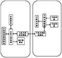
- FIG. 6 is a hardware block diagram of an implementation manner of the mobile terminal 100.
- the communication relationship between the host terminal 10 and the slave terminal 20 has various setting methods:
- the host terminal 10 includes a wireless modem module, a host main controller, and a host wireless transceiver module;
- the slave terminal 20 includes a slave keyboard, a slave host controller, and a wireless transceiver module with the host Wireless transceiver module for communication connection;
- the control command output from the keypad of the slave machine, under the control of the master controller of the slave machine, is modulated by the wireless transceiver module of the slave machine, and then sent to the host machine for wireless transceiver
- the module is received by the host wireless transceiver module and sent to the air after being modulated by the wireless modem module under the control of the host host controller;
- control signal from the air passes through the host main controller, is modulated by the host wireless transceiver module, and is sent to the slave terminal 20. After the slave wireless transceiver module receives it, it is displayed on the display screen 21 by the slave main controller. Displayed.
- both the host wireless communication module and the slave wireless communication module are Bluetooth modules or both are wifi modules.
- Bluetooth is a wireless technology standard that can implement short-range data exchange between fixed devices, mobile terminals 100, and building personal area networks.
- the Bluetooth band is 2400–2483.5MHz (including guard band). This is a 2.4GHz short-range radio band in the industrial, scientific, and medical (ISM) band that does not require a license (but is not unregulated) worldwide.
- ISM industrial, scientific, and medical
- the host terminal 10 includes a wireless modem module, a host main controller, and a host wireless transceiver module
- the slave terminal 20 includes a slave main controller, a slave microphone, a slave handset, and a Submachine wireless transceiver module, submachine audio encoder and submachine audio decoder that communicate with the host wireless transceiver module;
- the audio signal from the handset microphone is encoded by the handset audio encoder and then transmitted to the handset main controller.
- the wireless transceiver module of the handset After being sent out and received by the wireless transceiver module of the host, under the control of the host main controller, it is transmitted to the wireless modem module, which is modulated by the wireless modem module and sent to the air;
- the signal from the air is demodulated by the wireless modem module and then transmitted to the host main controller. Under the control of the host main controller, it is transmitted to the host wireless transceiver module and passed by the host wireless transceiver module. After the modulation, it is sent to the handset 20, and the audio signal demodulated by the handset wireless transceiver module, under the control of the handset main controller, is decoded by the handset audio decoder and then output by the handset of the handset.
- the audio encoder of the sub-machine here can be a separate hardware unit, can also be integrated into the microphone, or can be integrated into the main controller of the sub-machine, as far as its function is concerned, it can also have audio decoding Functional audio codec.
- the slave audio decoder here can be a separate hardware unit, it can also be integrated in the handset, or it can be integrated in the master controller of the slave, as far as its function is concerned, it can be an audio codec with audio encoding function. .
- the host terminal 10 includes a wireless modem module, a host main controller, and a host wireless transceiver module; the slave terminal 20 includes a slave wireless transceiver module capable of communicating with the host wireless transceiver module.
- the terminal 20 can access the communication network through the host 10.
- the host terminal 10 includes a host first wireless communication module, a host main controller, and a host second wireless communication module; the slave includes a slave wireless communication module, and the slave wireless communication module can communicate with the host The first wireless communication module communicates for communication, and the second wireless communication module of the host can communicate with the base station.
- the fingerprint identification module 23 includes an outer peripheral surface 232 connected to the identification surface 231.
- the outer peripheral surface 232 abuts the hole wall 2211 of the first through hole 221.
- the hole wall 2211 of the first through hole 221 bears against the outer peripheral surface 232 of the fingerprint recognition module 23 to stably restrict the fingerprint recognition module 23 on the first circuit board 22, thereby increasing the fingerprint recognition module 23 The firmness of the connection with the first circuit board 22.
- the slave terminal 20 includes a buffer 233.
- the buffer member 233 is disposed between the outer peripheral surface 232 of the fingerprint identification module 23 and the hole wall 2211 of the first through hole 221.
- the buffer member 233 may be, but not limited to, foam. Specifically, one side of the foam is adhered to the hole wall 2211 of the first through hole 221, and the other side is attached to the outer circumferential surface 232 of the fingerprint identification module 23.
- the buffer member 233 can buffer the first circuit when using the handset 20
- the pressure between the board 22 and the fingerprint identification module 23 ensures that the fingerprint identification module 23 is not easily damaged.
- the slave main controller 24 is fixed to the first circuit board 22 and connected to the display screen 21 and the fingerprint recognition module 23.
- the first circuit board 22 is the main board of the slave terminal 20.
- the slave main controller 24 controls the display screen 21 to display the image.
- the slave main controller 24 controls the fingerprint recognition module 23 to recognize the fingerprint.
- the connection line between the fingerprint identification module 23 and the slave main controller 24 is the shortest. At this time, the fingerprint identification module 23 The faster the data transmission, the better the sensitivity of the fingerprint identification module.
- the display screen 21 includes a screen body 211 and a flexible circuit board 212 connected to the screen body 211.
- the screen 211 is used to display images.
- the flexible circuit board 212 is located between the screen body 211 and the first circuit board 22.
- the slave main controller 24 controls the screen body 211 to display the image through the first circuit board 22 and the flexible circuit board 212.
- the flexible circuit board 212 is provided with a second through hole 2121.
- the second through hole 2121 is directly opposite to the first through hole 221.
- the identification surface 231 of the fingerprint identification module 23 collects the light outside the slave terminal 20 through the second through hole 2121.
- the fingerprint identification module 23 is partially accommodated inside the second through hole 2121 to further improve the space utilization rate of the handset 20.
- the fingerprint recognition module 23 is closer to the user's fingerprint, so that the fingerprint recognition module 23 detects more accurately.
- the outer peripheral surface 232 of the fingerprint identification module 23 partially abuts the hole wall of the second through hole 2121.
- one end of the flexible circuit board 212 extends to the side of the first circuit board 22 away from the display screen 21 through the peripheral position of the first circuit board 22, and is connected to the first circuit board 22.
- the space utilization rate of the slave terminal 20 is improved.
- the handset 20 includes a battery 25 and a second circuit board 26. It can be understood that the battery 25 can be used to provide power for the display screen 21 and the fingerprint identification module 23.
- the second circuit board 26 can be used to electrically connect devices such as a camera, a structured light module, or a receiver, that is, the second circuit board 26 is a sub board of the slave terminal 20.
- the handset 20 further includes a cover 291.
- the cover plate 291 is located on the side of the middle plate 28 away from the display screen 21. The periphery of the cover plate 291 covers the periphery of the frame 29 to protect the first circuit board 22, the battery 25, the second circuit board 26 and other devices.
- the battery 25 and the second circuit board 26 are located on the side of the display screen 21 facing away from the light exit surface 213, and the first circuit board 22, the battery 25, and the second circuit board 26 are sequentially in the length direction of the slave terminal 20 Arrange.
- the length of the first circuit board 22 in the length direction of the slave terminal 20 is greater than the length of the flexible circuit board 212 in the length direction of the slave terminal 20.
- the length of the second circuit board 26 in the length direction of the slave terminal 20 is smaller than the length of the flexible circuit board 212 in the length direction of the slave terminal 20.
- the flexible circuit board 212 is disposed between the second circuit board 26 and the screen body 211 (since the length of the flexible circuit board 212 is greater than the length of the second circuit board 26, and the first circuit board 22, the battery 25 and The second circuit boards 26 are sequentially arranged in the length direction of the slave terminal 20, so that the length of the slave terminal 20 includes the length of the flexible circuit board 26, the length of the battery 25, and the length of the first circuit board 22)
- the first circuit board 22 is disposed between the screen body 211 and the first circuit board 22 (because the length of the flexible circuit board 212 is shorter than the length of the first circuit board 22, and the first circuit board 22, the battery 25 and the first
- the two circuit boards 26 are sequentially arranged in the length direction of the slave terminal 20, so that the length of the slave terminal 20 includes the length of the first circuit board 22, the length of the battery 25, and the length of the second circuit board 26), making this embodiment
- the length of the slave terminal 20 of the example is significantly reduced.
- the length of the battery 25 can be increased accordingly to ensure that the overall length of the slave terminal 20 does not decrease. At this time, when the length of the battery 25 increases, the battery 25 has a larger capacity, and thus provides a longer use time for the handset 20.
- the first circuit board 22 in the length direction of the slave terminal 20 is greater than the length of the second circuit board 26 in the length direction of the slave terminal 20, the first circuit board 22 can be provided with more functional devices , Such as flash memory chips or microphones. At this time, the connection line between these functional devices and the slave main controller 24 is the shortest, making the sensitivity of the functional device higher.
- the thickness of the slave terminal 20 in the direction perpendicular to the light exit surface 213 is greater than or equal to 3 mm and less than or equal to 4 mm.
- the maximum thickness of the slave terminal 20 and the host terminal 10 in the direction perpendicular to the light exit surface 213 is greater than or equal to 9 mm and less than or equal to 13 mm.
- the thickness of the slave terminal 20 in the direction perpendicular to the light exit surface 213 is significantly smaller than the thickness of the conventional mobile terminal 100, so as to ensure the realization of the slimness of the slave terminal 20.
- the slave terminal 20 further includes a frame 29 and a middle plate 28.
- the frame 29 surrounds the periphery of the middle plate 28. It can be understood that the frame 29 and the middle plate 28 may be integrally formed, or may be fitted by splicing.
- the periphery of the display screen 21 is fixed to the inner side of the bezel 29 and is disposed opposite to the middle plate 28. It can be understood that the light exit surface 213 is located on the side of the display screen 21 facing away from the middle plate 28.
- the first circuit board 22 and the fingerprint recognition module 23 are disposed on the side of the middle board 28 away from the display screen 21. At this time, by setting the first circuit board 22 on the side of the middle board 28 away from the display screen 21, the electrical signal on the first circuit board 22 is prevented from affecting the display of the display screen 21.
- the middle plate 28 is provided with a third through hole 281.
- the third through hole 281 is directly opposite to the first through hole 221.
- the identification surface 231 of the fingerprint identification module 23 collects the light outside the slave terminal 20 through the third through hole 281. It can be understood that the size of the third through hole 281 is larger than the size of the first through hole 221, so that the fingerprint identification module 23 can detect the user's fingerprint in the largest area.
- the fingerprint identification module Part 23 is housed inside the third through hole 281 to further improve the space utilization of the handset 20. In addition, the fingerprint recognition module 23 is closer to the user's fingerprint, so that the fingerprint recognition module 23 detects more accurately.
- the outer peripheral surface 232 of the fingerprint identification module 23 partially abuts the hole wall 2811 of the third through hole 281. Furthermore, a buffer element may also be provided between the hole wall 2811 of the third through hole 281 and the outer peripheral surface 232 of the fingerprint identification module 23 to prevent the fingerprint identification module 23 and the middle plate 28 from being worn due to friction.
- the middle plate 28 is provided with a battery hole 289 through which the battery 25 abuts the screen body 211.
- the second circuit board 26 is disposed on the side of the middle board 28 away from the screen 211.
- the slave unit The length of the terminal 20 includes the length of the first circuit board 22, the length of the battery 25, and the length of the second circuit board 26, so that the length of the slave terminal 20 of this embodiment is significantly reduced.
- the length of the battery 25 can be increased accordingly to ensure that the overall length of the slave terminal 20 does not decrease. At this time, when the length of the battery 25 increases, the battery 25 has a larger capacity, and thus provides a longer use time for the handset 20.
- the middle plate 28 includes a side surface 282 and a first plate surface 283 and a second plate surface 284 disposed opposite to each other.
- the side surface 282 is connected between the first plate surface 283 and the second plate surface 284.
- the first panel 283 faces the display screen 21.
- the first board surface 283 is provided with an escape groove 285.
- the escape groove 285 penetrates the second plate surface 284 and the side surface 282.
- the flexible circuit board 212 extends to the side of the first circuit board 22 away from the display screen 21 through the escape groove 285. At this time, the flexible circuit board 212 can use the gap between the middle board 28 and the frame 29, thereby significantly improving the space utilization rate of the handset 20.
- the groove wall of the avoidance groove 285 can effectively limit the movement of the flexible circuit board 212, that is, to ensure the reliability of the connection between the display screen 21 and the first circuit board 22.
- the host 10 includes a first surface 11 and a second surface 12 that are opposite to each other.
- the first surface 11 is a curved surface.
- the middle of the first surface 11 is recessed in the direction of the second surface 12 to form the first groove 13.
- the slave terminal 20 can be detachably installed in the first groove 13. It can be understood that the shape of the first groove 13 is substantially the same as the shape of the slave end 20. When the slave terminal 20 is detachably installed in the first groove 13, the slave terminal 20 can be partially or fully received in the first groove 13. At this time, the thickness of the host end 10 and the slave end 20 in the stacked state will be significantly reduced.
- the slave terminal 20 includes a peripheral side 201 and a back 202.
- the back surface 202 is opposite to the light exit surface 213.
- the peripheral side surface 201 is connected between the light exit surface 213 and the back surface 202.
- the groove side wall 131 of the first groove 13 has a resisting force against the slave end 20, thereby To prevent the slave terminal 20 from falling off from the host terminal 10, thereby reducing the risk of damaging the mobile terminal 100, on the other hand, to ensure the consistency of the appearance of the mobile terminal 100, that is, to avoid excessively obvious gaps on the outer surface of the mobile terminal 100, affecting movement The appearance of the terminal 100.
- the mobile terminal 100 includes a second handset.
- the second slave terminal can be detachably installed on the host terminal 10. It can be understood that the structure of the second slave terminal and the structure of the slave terminal 20 may be the same.
- the second slave terminal communicates with the host terminal 10 in communication. At this time, different users can respectively communicate with the host terminal 10 through the slave terminal 20 and the second slave terminal.
- the slave terminal 20 includes a battery 28 and a second circuit board 29.
- the battery 28 and the second circuit board 29 are located on the side of the display screen 21 facing away from the light exit surface 213, and the first circuit board 22, the battery 28, and the second circuit board 29 are located
- the slave terminals 20 are sequentially arranged in the length direction.
- the second circuit board 29 is provided with a slave main controller 24.
- the slave main controller 24 is connected to the fingerprint recognition module 23 and the display screen 21. It can be understood that the first circuit board 22 is a sub board of the slave terminal 20.
- the second circuit board 29 is the main board of the slave terminal 20.
- the fingerprint recognition module 23 and the display screen 21 can be electrically connected to the slave main controller 24 through a flexible circuit board.
- the size of the first circuit board 22 can be significantly reduced compared to the setting of the sub-machine main controller 24 on the first circuit board 22, and the setting of the sub-machine main controller 24 on the second circuit board 29 .
- the present application also provides another mobile terminal 100.
- the mobile terminal 100 includes a display screen 10, a first circuit board 20, and a fingerprint recognition module 30.
- the display screen 10 has a light exit surface 11.
- the first circuit board 20 is located on the side of the display screen 10 facing away from the light exit surface 11.
- the display screen 10 is connected to the first circuit board 20.
- the first circuit board 20 is provided with a first through hole 21.
- the fingerprint identification module 30 is wholly or partially located in the first through hole 21, and the identification surface 31 of the fingerprint identification module 30 faces the display screen 10.
- the first through-hole 21 is provided on the first circuit board 20 of the mobile terminal 100, and the fingerprint identification module 30 is entirely or partially disposed in the first through-hole 21, so that the interior of the mobile terminal 100
- the arrangement between each component is compact and the space utilization rate is high.
- the internal arrangement of the mobile terminal 100 is relatively compact, the internal space of the mobile terminal 100 can be arranged with more other electronic devices, thereby making the functions of the mobile terminal 100 more diversified.
- the fingerprint identification module 30 is entirely or partially disposed in the first through-hole 21, so that the thickness of the mobile terminal 100 in the direction perpendicular to the light exit surface 11 can be reduced, and thus the mobile terminal 100 can be thinned.
- the mobile terminal 100 includes a main controller 40.
- the main controller 40 is fixed to the first circuit board 20 and connected to the fingerprint recognition module 30 and the display screen 10. It can be understood that when the user needs to activate the display screen 10 to display the image, the main controller 40 controls the display screen 10 to display the image. When the user needs to activate the fingerprint recognition module 30 to recognize the fingerprint, the main controller 40 controls the fingerprint recognition module 30 to recognize the fingerprint.
- the display screen 10 includes a screen body 12 and a flexible circuit board 13 connected to the screen body 12.
- the flexible circuit board 13 is located between the screen body 12 and the first circuit board 20.
- the flexible circuit board 13 is provided with a second through hole 131.
- the second through hole 131 faces the first through hole 21.
- the identification surface 31 of the fingerprint identification module 30 collects light outside the mobile terminal 100 through the second through hole 131.
- one end of the flexible circuit board 13 extends to the side of the first circuit board 20 away from the display screen 10 through the peripheral position of the first circuit board 20, and is connected to the first circuit board 20.
- the mobile terminal 100 includes a case 70, a battery 50 and a second circuit board 60.
- the first circuit board 20, the battery 50 and the second circuit board 60 are provided inside the housing 70.
- the battery 50 can be used to provide power for the display screen 10 and the fingerprint identification module 30.
- the second circuit board 60 can be used to electrically connect devices such as a camera, a structured light module, or a receiver.
- the battery 50 and the second circuit board 60 are located on the side of the display screen 10 facing away from the light exit surface 11, and the first circuit board 20, the battery 50 and the second circuit board 60 are arranged in sequence in the longitudinal direction of the mobile terminal 100.
- the length of the first circuit board 20 in the length direction of the mobile terminal 100 is greater than the length of the flexible circuit board 13 in the length direction of the mobile terminal 100, and the length of the second circuit board 60 in the length direction of the mobile terminal 100 is less than The length of the flexible circuit board 13 in the length direction of the mobile terminal 100.
- the first circuit board 20 can be set more Functional devices, such as flash memory chips or microphones. At this time, the connection line between these functional devices and the slave main controller 40 is the shortest, making the sensitivity of the functional device higher.
- the flexible circuit board 13 is disposed between the second circuit board 60 and the screen body 12 (since the length of the flexible circuit board 13 is greater than the length of the second circuit board 60, and the first circuit board 20, battery 50 and The second circuit boards 60 are sequentially arranged in the length direction of the mobile terminal 100, so that the length of the mobile terminal 100 includes the length of the flexible circuit board 13, the length of the battery 50, and the length of the first circuit board 20), and in this embodiment
- the first circuit board 20 is arranged between the screen body 12 and the first circuit board 20 (because the length of the flexible circuit board 13 is shorter than the length of the first circuit board 20, and the first circuit board 20, the battery 50 and the second circuit
- the boards 60 are sequentially arranged in the length direction of the mobile terminal 100, so that the length of the mobile terminal 100 includes the length of the first circuit board 20, the length of the battery 50, and the length of the second circuit board 60), so that the mobile terminal of this embodiment
- the length of 100 is significantly reduced.
- the length of the battery 50 can be increased accordingly to ensure that the overall length of the mobile terminal 100 does not decrease. At this time, when the length of the battery 50 increases, the battery 50 has a larger capacity, thereby providing the mobile terminal 100 with a longer use time.
- the thickness of the mobile terminal 100 in the direction perpendicular to the light exit surface 11 is greater than or equal to 3 mm and less than or equal to 4 mm. At this time, the thickness of the mobile terminal 100 in the direction perpendicular to the light exit surface 11 is significantly smaller than the thickness of the conventional mobile terminal 100, so as to ensure the realization of thinning and thinning of the mobile terminal 100.
Landscapes
- Engineering & Computer Science (AREA)
- Theoretical Computer Science (AREA)
- Human Computer Interaction (AREA)
- Physics & Mathematics (AREA)
- General Engineering & Computer Science (AREA)
- General Physics & Mathematics (AREA)
- Telephone Set Structure (AREA)
Abstract
本申请公开了一种移动终端。所述移动终端包括主机端及子机端,所述子机端能够可拆卸安装于所述主机端,所述子机端包括显示屏、第一电路板及指纹识别模组,所述显示屏具有出光面,所述第一电路板位于所述显示屏背离所述出光面的一侧,所述显示屏连接所述第一电路板,所述第一电路板设有第一通孔,所述指纹识别模组全部或者部分位于所述第一通孔内,且所述指纹识别模组的识别面朝向所述显示屏。所述移动终端的空间利用率较高。
Description
本申请涉及一种移动终端技术领域,尤其涉及一种移动终端。
随着移动终端技术的日趋发展,人们希望手机中能够集成更多的器件,以实现更多样化的功能。然而,随着在移动终端内部安装的器件越来越多,使得移动终端的机体也越来越大,从而阻碍了移动终端的轻薄化设置,已经不能够满足用户需求。
申请内容
本申请提供一种移动终端。
本申请提供了一种移动终端。所述移动终端包括主机端及子机端,所述子机端能够可拆卸安装于所述主机端,所述子机端包括显示屏、第一电路板及指纹识别模组,所述显示屏具有出光面,所述第一电路板位于所述显示屏背离所述出光面的一侧,所述显示屏连接所述第一电路板,所述第一电路板设有第一通孔,所述指纹识别模组全部或者部分位于所述第一通孔内,且所述指纹识别模组的识别面朝向所述显示屏。
本申请还提供了一种移动终端。所述移动终端包括显示屏、第一电路板及指纹识别模组,所述显示屏具有出光面,所述第一电路板位于所述显示屏背离所述出光面的一侧,所述显示屏连接所述第一电路板,所述第一电路板设有第一通孔,所述指纹识别模组全部或部分位于所述第一通孔内,且所述指纹识别模组的识别面朝向所述显示屏。
在本实施例中,通过在所述子机端的电路板上设置第一通孔,并将所述指纹识别模组全部或部分设于所述第一通孔内,使得所述子机端的内部各个部件之间排布紧凑,空间利用率高。此外,由于所述子机端的内部排布较为紧凑,使得所述子机端的内部空间能够排布更多的其他电子器件,从而使得所述移动终端的功能更为多样化。再者,所述指纹识别模组全部或部分设于所述第一通孔内,从而能够减小所述子机端在垂直于所述出光面的方向上的厚度,进而实现所述移动终端的薄形化设置。
为了更清楚地说明本申请的技术方案,下面将对实施方式中所需要使用的附图作简单地介绍,显而易见地,下面描述中的附图仅仅是本申请的一些实施方式,对于本领域普通技术人员来讲,在不付出创造性劳动的前提下,还可以如这些附图获得其他的附图。
图1是本申请实施例提供的一种移动终端在一种使用状态中的结构示意图;
图2是图1所示移动终端中的主机端的结构示意图;
图3是图1所示移动终端中的子机端的结构示意图;
图4是图3所示子机端的一种实施方式的分解示意图;
图5是图3所示的子机端在A-A线处的一种实施方式的部分剖面示意图;
图6是图1所示移动终端的一种实施方式的硬件结构框图;
图7是图6所示移动终端在一种工作状态下的硬件结构框图;
图8是图6所示移动终端在另一种工作状态下的硬件结构框图;
图9是图6所示移动终端在再一种工作状态下的硬件结构框图;
图10是图6所示移动终端在再一种工作状态下的硬件结构框图;
图11是图1所示移动终端的另一种实施方式的硬件结构框图;
图12是图1所示移动终端的再一种实施方式的硬件结构框图;
图13是图3所示的子机端在A-A线处的另一种实施方式的部分剖面示意图;
图14是图3所示的子机端在A-A线处的再一种实施方式的部分剖面示意图;
图15是图3所示的子机端在A-A线处的再一种实施方式的部分剖面示意图;
图16是图1所示的移动终端在另一种角度的结构示意图;
图17是图3所示子机端的盖板的结构的示意图;
图18是图3所示子机端的另一种实施方式的部分分解示意图;
图19是本申请实施例提供的另一种移动终端中的结构示意图;
图20是图19所示的移动终端在B-B线处的一种实施方式的部分剖面示意图;
图21是图19所示的移动终端的部分分解示意图。
下面将结合本申请实施方式中的附图,对本申请实施方式中的技术方案进行清楚、完整地描述。
为了能够更清楚地理解本申请的上述目的、特征和优点,下面结合附图和具体实施方式对本申请进行详细描述。需要说明的是,在不冲突的情况下,本申请的实施方式及实施方式中的特征可以相互组合。
在下面的描述中阐述了很多具体细节以便于充分理解本申请,所描述的实施方式仅仅是本申请一部分实施方式,而不是全部的实施方式。基于本申请中的实施方式,本领域普通技术人员在没有做出创造性劳动前提下所获得的所有其他实施方式,都属于本申请保护的范围。
请参阅图1至图3。附图1为本申请实施方式提供的一种移动终端100。附图2为图1所示移动终端100的主机端10的结构示意图。附图3是图1所示移动终端100的子机端10的结构示 意图。移动终端100包括主机端10及子机端20。可选的,主机端10能够与子机端20通信连接。子机端20能够可拆卸安装于主机端10。可以理解的是,子机端20能够安装于主机端10指的是子机端20能够直接放置于主机端10上,或者子机端20能够通过紧固件可拆卸固定在主机端10上,或者子机端20滑动连接或转动连接于主机端10上。具体的本申请不作限定。
再者,如图3至图5所示,附图4是图3所示的子机端20的结构部分分解示意图。附图5为图3所示的子机端20在A-A线处的部分剖面示意图。子机端20包括显示屏21、第一电路板22及指纹识别模组23。显示屏21具有出光面213。可以理解的是,当显示屏21的出光面213朝向用户,且光线经出光面213发出时,用户能够通过出光面213观看图像。第一电路板22位于显示屏21背离出光面213的一侧。显示屏21连接第一电路板22。此时,显示屏21能够与第一电路板22通电连接,以实现图像显示。第一电路板22设有第一通孔221。指纹识别模组23全部或者部分位于第一通孔221内,且指纹识别模组23的识别面231朝向显示屏21。
在本实施例中,通过在子机端20的第一电路板22上设置第一通孔221,并将指纹识别模组23全部或部分设于第一通孔221内,使得子机端20的内部各个部件之间排布紧凑,空间利用率高。此外,由于子机端20的内部排布较为紧凑,使得子机端20的内部空间能够排布更多的其他电子器件,从而使得移动终端100的功能更为多样化。再者,指纹识别模组23全部或部分设于第一通孔221内,从而能够减小子机端20在垂直于出光面213的方向上的厚度,进而实现移动终端100的薄形化设置。
在本实施例中,附图6为移动终端100的一种实施方式的硬件结构框图。主机端10与子机端20的通信关系具有多种设置方式:
实施方式一,如图6所示,主机端10包括无线调制解调模块、主机主控制器、主机无线收发模块;子机端20包括子机键盘、子机主控制器及与主机无线收发模块通信连接的子机无线收发模块;
如图7所示,在移动终端100的第一种工作状态下,子机键盘输出的控制命令,在子机主控制器的控制下,经子机无线收发模块调制后,发给主机无线收发模块,主机无线收发模块接收,并在主机主控制器控制下,经无线调制解调模块调制后,发送到空中;
如图8所示,来自空中的控制信号,经过主机主控制器,由主机无线收发模块调制后发给子机端20,子机无线收发模块接收后,经子机主控制器在显示屏21中显示。
进一步的,主机无线通信模块与子机无线通信模块均为蓝牙模块或均为wifi模块。可以理解的是,蓝牙是一种无线技术标准,可实现固定设备、移动终端100和楼宇个人域网之间的短距离数据交换。蓝牙的波段为2400–2483.5MHz(包括防护频带)。这是全球范围内无需取得执照(但并非无管制的)的工业、科学和医疗用(ISM)波段的2.4GHz短距离无线电频段。
实施方式二,如图6所示,主机端10包括无线调制解调模块、主机主控制器、主机无线 收发模块,子机端20包括子机主控制器、子机话筒、子机听筒、能够与主机无线收发模块通信的子机无线收发模块、子机音频编码器及子机音频解码器;
如图9所示,在工作状态下,来自子机话筒的音频信号,经子机音频编码器编码后传输到子机主控制器中,经子机主控制器控制下,被子机无线收发模块发送出去,由主机无线收发模块接收后,在主机主控制器的控制下,传送到无线调制解调模块,经无线调制解调模块调制后发送到空中;
如图10所示,来自空中的信号,经无线调制解调模块解调后传送到主机主控制器中,在主机主控制器的控制下,传送到主机无线收发模块中,经主机无线收发模块调制后,发送到子机端20中,子机无线收发模块解调出的音频信号,在子机主控制器控制下,经子机音频解码器解码后,由子机听筒输出。
可以理解的是,这里的子机音频编码器,可以是单独的硬件单元,也可以集成在话筒中,也可以集成在子机主控制器中,就其功能而言可以是兼具有音频解码功能的音频编解码器。
这里的子机音频解码器可以是单独的硬件单元,也可以集成在听筒中,也可以集成在子机主控制器中,就其功能而言可以是兼具有音频编码功能的音频编解码器。
实施方式三,如图11所示,主机端10包括无线调制解调模块、主机主控制器、主机无线收发模块;子机端20包括与主机无线收发模块能够通信的子机无线收发模块,子机端20能够通过主机端10接入通信网络。
实施方式四,如图12所示,主机端10包括主机第一无线通信模块、主机主控制器、主机第二无线通信模块;子机包括子机无线通信模块,子机无线通信模块能够与主机第一无线通信模块通信进行通信,主机第二无线通信模块能够与基站通信。
在本实施例中,请再次参考附图5,指纹识别模组23包括连接于识别面231的外周面232。外周面232抵持于第一通孔221的孔壁2211。此时,通过第一通孔221的孔壁2211抵持于指纹识别模组23的外周面232,以将指纹识别模组23稳定地限制在第一电路板22上,从而增加指纹识别模组23与第一电路板22的连接牢固度。
进一步的,如图13所示,子机端20包括缓冲件233。所述缓冲件233设于所述指纹识别模组23外周面232与所述第一通孔221的孔壁2211之间。可以理解的是,缓冲件233可以为但不仅限于为泡棉。具体的,泡棉的一面粘接于第一通孔221的孔壁2211上,另一面贴于指纹识别模组23的外周面232。此时,通过在指纹识别模组23的外周面232与所述第一通孔221的孔壁2211之间设置缓冲件233,以在使用子机端20时,缓冲件233能够缓冲第一电路板22与指纹识别模组23之间的压力,从而保证指纹识别模组23不易被破坏。
在本实施例中,请再次参考图4,子机主控制器24固定于第一电路板22且连接显示屏21及指纹识别模组23。可以理解的是,第一电路板22为子机端20的主板。当用户需要启动显 示屏21显示图像时,子机主控制器24控制显示屏21显示图像。当用户需要启动指纹识别模组23识别指纹时,子机主控制器24控制指纹识别模组23识别指纹。此外,当子机主控制器24与指纹识别模组23均设于第一电路板22,使得指纹识别模组23与子机主控制器24的连接线路最短,此时,指纹识别模组23的传输数据较快,使得指纹识别模组的灵敏性更佳。
进一步的,请再次参考图5,显示屏21包括屏体211及连接屏体211的柔性电路板212。屏体211用于显示图像。柔性电路板212位于屏体211与第一电路板22之间。当用户需要启动显示屏21显示电子图像时,子机主控制器24通过第一电路板22及柔性电路板212控制屏体211显示图像。柔性电路板212设有第二通孔2121。第二通孔2121正对第一通孔221设置。指纹识别模组23的识别面231经第二通孔2121采集子机端20外部的光线。进一步的,指纹识别模组23部分收容于第二通孔2121内部,以进一步的提高子机端20的空间利用率。此外,指纹识别模组23更靠近用户的指纹,使得指纹识别模组23检测更加的准确。再者,指纹识别模组23的外周面232部分抵持于第二通孔2121的孔壁上。
可选的,如图15所示,柔性电路板212的一端经第一电路板22的周侧位置延伸至第一电路板22远离显示屏21的一侧,且连接第一电路板22。此时,通过将部分柔性电路板212设置在第一电路板22的周侧,以有效地利用第一电路板22的周侧位置,从而提高子机端20的空间利用率。
在本实施例中,请再次参考图4,子机端20包括电池25及第二电路板26。可以理解的是,电池25能够用于为显示屏21及指纹识别模组23提供电能。第二电路板26能够用于摄像头、结构光模组或受话器等器件通电连接,即第二电路板26为子机端20的副板。此外,请结合附图16,子机端20还包括盖板291。盖板291位于中板28远离显示屏21的一侧。盖板291的周缘盖合于边框29的周缘,以保护第一电路板22、电池25及第二电路板26等器件。
可以理解的是,电池25及第二电路板26位于显示屏21背离出光面213的一侧,且第一电路板22、电池25及第二电路板26在子机端20的长度方向上依次排布。第一电路板22在子机端20的长度方向上的长度大于柔性电路板212在子机端20的长度方向上的长度。第二电路板26在子机端20的长度方向上的长度小于柔性电路板212在子机端20的长度方向上的长度。故而,相较于将柔性电路板212设置在第二电路板26与屏体211之间(由于柔性电路板212的长度大于第二电路板26的长度,且第一电路板22、电池25及第二电路板26在子机端20的长度方向上依次排布,使得子机端20的长度包括柔性电路板26的长度、电池25的长度以及第一电路板22的长度),而在本实施例中将第一电路板22设置在屏体211与第一电路板22之间(由于柔性电路板212的长度小于第一电路板22的长度,且第一电路板22、电池25及第二电路板26在子机端20的长度方向上依次排布,使得子机端20的长度包括第一电路板22的长度、电池25的长度以及第二电路板26的长度),使得本实施例的子机端20的长度显著减小。故而,在本实施例中,可相应地通过增长电池25的长度,以保证子机端20的整体长度不会减小。 此时,当电池25长度的增长,使得电池25具有更大的容量,进而为子机端20提供更久的使用时间。
此外,当第一电路板22在子机端20的长度方向上的长度大于第二电路板26在子机端20的长度方向上的长度,使得第一电路板22能够设置更多的功能器件,例如闪存芯片或者麦克风。此时,该些功能器件与子机主控制器24的连接线路最短,使得该功能器件的灵敏度更高。
在本实施例中,子机端20在垂直于出光面213的方向的厚度大于等于3毫米且小于等于4毫米。当子机端20可拆卸安装于主机端10时,子机端20与主机端10在垂直于出光面213的方向的最大厚度大于等于9毫米且小于等于13毫米。此时,子机端20在垂直于出光面213方向的厚度显著地小于传统的移动终端100的厚度,以保证子机端20的轻薄化的实现。
在本实施例中,请再次参考附图4及图5,子机端20还包括边框29及中板28。边框29围设在中板28的周缘。可以理解的是,边框29与中板28可以一体成型,也可以通过拼接配合。显示屏21的周缘固定于边框29的内侧,且与中板28相对设置。可以理解的是,出光面213位于显示屏21背离中板28的一侧。第一电路板22及指纹识别模组23设于中板28远离显示屏21的一侧。此时,通过将第一电路板22设于中板28远离显示屏21的一侧,以避免第一电路板22上的电信号影响显示屏21的显示。
再者,请再次参考图4及图5,中板28设有第三通孔281。第三通孔281正对第一通孔221设置。指纹识别模组23的识别面231经第三通孔281采集子机端20外部的光线。可以理解的是,第三通孔281的大小大于第一通孔221的大小,以使指纹识别模组23能够最大面积的检测用户的指纹,进一步的,如图14所示,指纹识别模组23部分收容于第三通孔281的内部,以进一步的提高子机端20的空间利用率。此外,指纹识别模组23更靠近用户的指纹,使得指纹识别模组23检测更加的准确。再者,指纹识别模组23的外周面232部分抵持于第三通孔281的孔壁2811上。再者,第三通孔281的孔壁2811与指纹识别模组23的外周面232之间也可以设置缓冲件,以避免指纹识别模组23与中板28因产生摩擦而发生损耗。
进一步的,如图4所示,中板28设有电池孔289,电池25穿过电池孔289抵接于屏体211。第二电路板26设于中板28远离屏体211的一侧。此时,由于柔性电路板212的长度小于第一电路板22的长度,且第一电路板22、电池25及第二电路板26在子机端20的长度方向上依次排布,使得子机端20的长度包括第一电路板22的长度、电池25的长度以及第二电路板26的长度,使得本实施例的子机端20的长度显著减小。故而,在本实施例中,可相应地通过增长电池25的长度,以保证子机端20的整体长度不会减小。此时,当电池25长度的增长,使得电池25具有更大的容量,进而为子机端20提供更久的使用时间。
进一步的,如图15所示,中板28包括侧面282及相背设置的第一板面283及第二板面284。侧面282连接在第一板面283与第二板面284之间。第一板面283朝向显示屏21。第一板面283 设有避让槽285。避让槽285贯穿第二板面284及侧面282。柔性电路板212经避让槽285延伸至第一电路板22远离显示屏21的一侧。此时,柔性电路板212能够利用中板28与边框29之间的空隙,从而显著地提高子机端20的空间利用率。此外,当柔性电路板212穿过避让槽285时,避让槽285的槽壁能够有效地限制柔性电路板212的运动,即保证显示屏21与第一电路板22连接的可靠性。
在本实施例中,请再次参考图2,主机端10包括相背设置的第一面11及第二面12。第一面11为曲面。第一面11的中部向第二面12的方向凹陷以形成第一凹槽13。子机端20能够可拆卸地安装于第一凹槽13内。可以理解的是,第一凹槽13的形状与子机端20的形状大致相同。当子机端20可拆卸地安装于第一凹槽13内时,子机端20能够部分或全部收容于第一凹槽13内。此时,层叠状态下的主机端10与子机端20的厚度将显著降低。
进一步地,如图17所示并结合附图2,子机端20包括周侧面201及背面202。背面202与出光面213相背设置。周侧面201连接在出光面213及背面202之间。当子机端20可拆卸安装于第一凹槽13时,侧面201抵持于第一凹槽13的槽侧壁131。此时,子机端20大致占满第一凹槽13,从而显著提高主机端10的空间利用率。此外,当子机端20的周侧面201抵持于第一凹槽13的槽侧壁131时,一方面,第一凹槽13的槽侧壁131对子机端20具有抵持力,从而避免子机端20从主机端10中脱落,进而降低损坏移动终端100的风险,另一方面,保证移动终端100的外观一致性,即避免移动终端100的外表面存在过于明显的缝隙,影响移动终端100的美观。
在其他实施例中,移动终端100包括第二子机端。第二子机端能够可拆卸安装于主机端10上。可以理解的是,第二子机端的结构与子机端20的结构可以相同。第二子机端与主机端10通信连接。此时,不同的用户能够分别通过子机端20与第二子机端对主机端10实现通信连接。
在另一种实施例中,与上述实施例相同的技术内容不再赘述:如图18所示,子机端20包括电池28及第二电路板29。所述电池28及所述第二电路板29位于所述显示屏21背离所述出光面213的一侧,且所述第一电路板22、所述电池28及所述第二电路板29在所述子机端20的长度方向上依次排布。第二电路板29设有子机主控制器24。子机主控制器24连接于指纹识别模组23及显示屏21。可以理解的是,第一电路板22为子机端20的副板。第二电路板29为子机端20的主板。指纹识别模组23及显示屏21可以通过柔性电路板电连接于子机主控制器24。在本实施例中,相较于将子机主控制器24设于第一电路板22,将子机主控制器24设于第二电路板29可以显著地减小第一电路板22的尺寸。
如图19及图20所示,本申请还提供另一种移动终端100。移动终端100包括显示屏10、第一电路板20及指纹识别模组30。显示屏10具有出光面11。第一电路板20位于显示屏10背离出光面11的一侧。显示屏10连接第一电路板20。第一电路板20设有第一通孔21。指纹识 别模组30全部或部分位于第一通孔21内,且指纹识别模组30的识别面31朝向显示屏10。
在本实施例中,通过在移动终端100的第一电路板20上设置第一通孔21,并将指纹识别模组30全部或部分设于第一通孔21内,使得移动终端100的内部各个部件之间排布紧凑,空间利用率高。此外,由于移动终端100的内部排布较为紧凑,使得移动终端100的内部空间能够排布更多的其他电子器件,从而使得移动终端100的功能更为多样化。再者,指纹识别模组30全部或部分设于第一通孔21内,从而能够减小移动终端100在垂直于出光面11的方向上的厚度,进而实现移动终端100的薄形化设置。
在本实施例中,如图20所示,移动终端100包括主控制器40。主控制器40固定于第一电路板20且连接指纹识别模组30及显示屏10。可以理解的是,当用户需要启动显示屏10显示图像时,主控制器40控制显示屏10显示图像。当用户需要启动指纹识别模组30识别指纹时,主控制器40控制指纹识别模组30识别指纹。
进一步的,如图20所示,显示屏10包括屏体12及连接屏体12的柔性电路板13。柔性电路板13位于屏体12与第一电路板20之间。所述柔性电路板13设有第二通孔131。所述第二通孔131正对所述第一通孔21。所述指纹识别模组30的识别面31经所述第二通孔131采集所述移动终端100外部的光线。
可选的,柔性电路板13的一端经第一电路板20的周侧位置延伸至第一电路板20远离显示屏10的一侧,且连接第一电路板20。
进一步的,如图21所示,移动终端100包括壳体70、电池50及第二电路板60。第一电路板20、电池50及第二电路板60设于壳体70的内部。可以理解的是,电池50能够用于为显示屏10及指纹识别模组30提供电能。第二电路板60能够用于摄像头、结构光模组或受话器等器件通电连接。电池50及第二电路板60位于显示屏10背离出光面11的一侧,且第一电路板20、电池50及第二电路板60在移动终端100的长度方向上依次排布。
再者,第一电路板20在移动终端100的长度方向上的长度大于柔性电路板13在移动终端100的长度方向上的长度,第二电路板60在移动终端100的长度方向上的长度小于柔性电路板13在移动终端100的长度方向上的长度。可以理解的是,当第一电路板20在子机端20的长度方向上的长度大于第二电路板60在子机端20的长度方向上的长度,使得第一电路板20能够设置更多的功能器件,例如闪存芯片或者麦克风。此时,该些功能器件与子机主控制器40的连接线路最短,使得该功能器件的灵敏度更高。
此外,相较于将柔性电路板13设置在第二电路板60与屏体12之间(由于柔性电路板13的长度大于第二电路板60的长度,且第一电路板20、电池50及第二电路板60在移动终端100的长度方向上依次排布,使得移动终端100的长度包括柔性电路板13的长度、电池50的长度以及第一电路板20的长度),而在本实施例中将第一电路板20设置在屏体12与第一电路板20之间(由于柔性电路板13的长度小于第一电路板20的长度,且第一电路板20、电池50及第 二电路板60在移动终端100的长度方向上依次排布,使得移动终端100的长度包括第一电路板20的长度、电池50的长度以及第二电路板60的长度),使得本实施例的移动终端100的长度显著减小。故而,在本实施例中,可相应地通过增长电池50的长度,以保证移动终端100的整体长度不会减小。此时,当电池50长度的增长,使得电池50具有更大的容量,进而为移动终端100提供更久的使用时间。
再者,移动终端100在垂直于出光面11的方向的厚度大于等于3毫米且小于等于4毫米。此时,移动终端100在垂直于出光面11方向的厚度显著地小于传统的移动终端100的厚度,以保证移动终端100的轻薄化的实现。
以上是本申请的可选实施方式,应当指出,对于本技术领域的普通技术人员来说,在不脱离本申请原理的前提下,还可以做出若干改进和润饰,这些改进和润饰也视为本申请的保护范围。
Claims (20)
- 一种移动终端,其特征在于,包括主机端及子机端,所述子机端能够可拆卸安装于所述主机端,所述子机端包括显示屏、第一电路板及指纹识别模组,所述显示屏具有出光面,所述第一电路板位于所述显示屏背离所述出光面的一侧,所述显示屏连接所述第一电路板,所述第一电路板设有第一通孔,所述指纹识别模组全部或者部分位于所述第一通孔内,且所述指纹识别模组的识别面朝向所述显示屏。
- 如权利要求1所述的移动终端,其特征在于,所述指纹识别模组包括连接于所述识别面的外周面,所述外周面抵持于所述第一通孔的孔壁。
- 如权利要求2所述的移动终端,其特征在于,所述子机端包括缓冲件,所述缓冲件设于所述外周面与所述第一通孔的孔壁之间。
- 如权利要求1至3中任一项所述的移动终端,其特征在于,所述子机端包括子机主控制器,所述子机主控制器固定于所述第一电路板且连接所述显示屏及所述指纹识别模组。
- 如权利要求4所述的移动终端,其特征在于,所述显示屏包括屏体及连接所述屏体的柔性电路板,所述柔性电路板位于所述屏体与所述第一电路板之间,且连接于所述第一电路板,所述柔性电路板设有第二通孔,所述第二通孔正对所述第一通孔,所述指纹识别模组的识别面经所述第二通孔采集所述子机端外部的光线。
- 如权利要求5所述的移动终端,其特征在于,所述柔性电路板的一端经所述第一电路板的周侧位置延伸至所述第一电路板远离所述显示屏的一侧。
- 如权利要求5所述的移动终端,其特征在于,所述子机端包括电池及第二电路板,所述电池及所述第二电路板位于所述显示屏背离所述出光面的一侧,且所述第一电路板、所述电池及所述第二电路板在所述子机端的长度方向上依次排布,所述第一电路板在所述子机端的长度方向上的长度大于所述柔性电路板在所述子机端的长度方向上的长度,所述第二电路板在所述子机端的长度方向上的长度小于所述柔性电路板在所述子机端的长度方向上的长度。
- 如权利要求7所述的移动终端,其特征在于,所述子机端在垂直于所述出光面的方向的厚度大于等于3毫米且小于等于4毫米,且当所述子机端可拆卸安装于所述主机端时,所述子机端与所述主机端在垂直于所述出光面的方向的最大厚度大于等于9毫米且小于等于13毫米。
- 如权利要求1至8中任意一项所述的移动终端,其特征在于,所述主机端包括无线调制解调模块、主机主控制器、主机无线收发模块;所述子机端包括子机键盘、子机主控制器、显示屏及与所述主机无线收发模块通信连接的子机无线收发模块;在所述移动终端的第一种工作状态下,所述子机键盘输出的控制命令,经所述子机无线收发模块调制后,发给所述主机无线收发模块,所述主机无线收发模块接收,并在所述主机主控制器控制下,经所述无线调制解调模块调制后,发送到空中;来自空中的控制信号,经过所述主机主控制器,由所述主机无线收发模块调制后发给所述子机端,所述子机无线收发模块接收后,经所述子机主控制器在所述显示屏中显示。
- 如权利要求1至8中任意一项所述的移动终端,其特征在于,所述主机端包括无线调制解调模块、主机主控制器、主机无线收发模块,所述子机端包括子机主控制器、子机话筒、子机听筒、能够与所述主机无线收发模块通信的子机无线收发模块、子机音频编码器及子机音频解码器;在工作状态下,来自所述子机话筒的音频信号,经所述子机音频编码器编码后传输到所述子机主控制器中,经所述子机主控制器控制下,被所述子机无线收发模块发送出去,由所述主机无线收发模块接收后,在所述主机主控制器的控制下,传送到所述无线调制解调模块,经所述无线调制解调模块调制后发送到空中;来自空中的信号,经所述无线调制解调模块解调后传送到所述主机主控制器中,在所述主机主控制器的控制下,传送到所述主机无线收发模块中,经所述主机无线收发模块调制后,发送到所述子机端中,所述子机无线收发模块解调出的音频信号,在所述子机主控制器控制下,经所述子机音频解码器解码后,由所述子机听筒输出。
- 如权利要求1至8中任意一项所述的移动终端,其特征在于,所述主机端包括无线调制解调模块、主机主控制器、主机无线收发模块;所述子机端包括与所述主机无线收发模块能够通信的子机无线收发模块,所述子机端能够通过所述主机端接入通信网络。
- 如权利要求1至8中任意一项所述的移动终端,其特征在于,所述主机端包括主机第一无线通信模块、主机主控制器、主机第二无线通信模块;所述子机端包括子机无线通信模块,所述子机无线通信模块能够与主机第一无线通信模块通信,所述主机第二无线通信模块能够与基站通信。
- 如权利要求1至3中任一项所述的移动终端,其特征在于,所述子机端包括电池及第二电路板,所述电池及所述第二电路板位于所述显示屏背离所述出光面的一侧,且所 述第一电路板、所述电池及所述第二电路板在所述子机端的长度方向上依次排布,所述第二电路板设有子机主控制器,所述子机主控制器连接于所述指纹识别模组及所述显示屏。
- 如权利要求5至8中任意一项所述的移动终端,其特征在于,所述移动终端包括边框及中板,所述边框围设在所述中板的周缘,所述显示屏的周缘固定于所述边框的内侧,且与所述中板相对设置,所述第一电路板及所述指纹识别模组设于所述中板远离所述显示屏的一侧,所述中板设有第三通孔,所述第三通孔正对所述第二通孔设置,所述指纹识别模组的识别面经所述第三通孔采集所述子机端外部的光线。
- 如权利要求14所述的移动终端,其特征在于,所述指纹识别模组部分收容于所述第三通孔内,且所述指纹识别模组的外周面抵持于所述第三通孔的孔壁。
- 如权利要求14所述的移动终端,其特征在于,所述中板包括侧面及相背设置的第一板面及第二板面,所述侧面连接在所述第一板面与所述第二板面之间,所述第一板面朝向所述显示屏,所述第一板面设有避让槽,所述避让槽贯穿所述第二板面及所述侧面,所述柔性电路板经所述避让槽延伸至所述第一电路板远离所述显示屏的一侧。
- 一种移动终端,其特征在于,包括显示屏、第一电路板及指纹识别模组,所述显示屏具有出光面,所述第一电路板位于所述显示屏背离所述出光面的一侧,所述显示屏连接所述第一电路板,所述第一电路板设有第一通孔,所述指纹识别模组全部或部分位于所述第一通孔内,且所述指纹识别模组的识别面朝向所述显示屏。
- 如权利要求17所述的移动终端,其特征在于,所述移动终端包括主控制器,所述主控制器固定于所述第一电路板且连接于所述指纹识别模组及所述显示屏。
- 如权利要求18所述的移动终端,其特征在于,所述显示屏包括屏体及连接所述屏体的柔性电路板,所述柔性电路板位于所述屏体与所述第一电路板之间,且连接所述第一电路板,所述柔性电路板设有第二通孔,所述第二通孔正对所述第一通孔,所述指纹识别模组的识别面经所述第二通孔采集所述移动终端外部的光线。
- 如权利要求19所述的移动终端,其特征在于,所述移动终端包括电池及第二电路板,所述电池及所述第二电路板位于所述显示屏背离所述出光面的一侧,且所述第一电路板、所述电池及所述第二电路板在所述移动终端的长度方向上依次排布,所述第一电路板在所述移动终端的长度方向上的长度大于所述柔性电路板在所述移动终端的长度方向上的长度,所述第二电路板在所述移动终端的长度方向上的长度小于所述柔性电路板在所述移动终端的长度方向上的长度,且所述移动终端在垂直于所述出光面的方向的厚度大于等于 3毫米且小于等于4毫米。
Priority Applications (1)
| Application Number | Priority Date | Filing Date | Title |
|---|---|---|---|
| CN201980071279.3A CN112930536B (zh) | 2018-12-29 | 2019-05-29 | 移动终端 |
Applications Claiming Priority (2)
| Application Number | Priority Date | Filing Date | Title |
|---|---|---|---|
| CN201822277697.3 | 2018-12-29 | ||
| CN201822277697 | 2018-12-29 |
Publications (1)
| Publication Number | Publication Date |
|---|---|
| WO2020133906A1 true WO2020133906A1 (zh) | 2020-07-02 |
Family
ID=71127517
Family Applications (1)
| Application Number | Title | Priority Date | Filing Date |
|---|---|---|---|
| PCT/CN2019/089126 Ceased WO2020133906A1 (zh) | 2018-12-29 | 2019-05-29 | 移动终端 |
Country Status (2)
| Country | Link |
|---|---|
| CN (1) | CN112930536B (zh) |
| WO (1) | WO2020133906A1 (zh) |
Cited By (1)
| Publication number | Priority date | Publication date | Assignee | Title |
|---|---|---|---|---|
| CN114390807A (zh) * | 2020-10-16 | 2022-04-22 | 北京小米移动软件有限公司 | 中框及终端设备 |
Citations (6)
| Publication number | Priority date | Publication date | Assignee | Title |
|---|---|---|---|---|
| CN101610596A (zh) * | 2008-06-16 | 2009-12-23 | 北京华旗数码技术实验室有限责任公司 | 分体式移动通讯装置 |
| CN105159409A (zh) * | 2015-10-10 | 2015-12-16 | 广东欧珀移动通信有限公司 | 一种具有指纹传感器的移动终端 |
| CN106470527A (zh) * | 2015-08-21 | 2017-03-01 | 旭景科技股份有限公司 | 用于形成增强型指纹辨识模块的印刷电路板结构 |
| US20170061193A1 (en) * | 2015-09-02 | 2017-03-02 | Synaptics Incorporated | Fingerprint sensor under thin face-sheet with aperture layer |
| CN108447842A (zh) * | 2018-04-28 | 2018-08-24 | 苏州晶方半导体科技股份有限公司 | 一种指纹芯片的封装结构以及封装方法 |
| US20180300523A1 (en) * | 2015-10-12 | 2018-10-18 | Shanghai Oxi Technology Co., Ltd | Fingerprint Module |
Family Cites Families (5)
| Publication number | Priority date | Publication date | Assignee | Title |
|---|---|---|---|---|
| CN105138074B (zh) * | 2015-07-23 | 2017-06-23 | 广东欧珀移动通信有限公司 | 终端 |
| CN206863774U (zh) * | 2017-06-29 | 2018-01-09 | 南昌欧菲生物识别技术有限公司 | 手持终端及其指纹识别显示屏 |
| CN107577278B (zh) * | 2017-09-14 | 2020-02-04 | 维沃移动通信有限公司 | 一种显示屏组件及移动终端 |
| CN207965907U (zh) * | 2017-09-14 | 2018-10-12 | 中兴通讯股份有限公司 | 一种指纹识别模组、触控显示屏及移动终端 |
| CN207182346U (zh) * | 2017-09-15 | 2018-04-03 | 南昌欧菲生物识别技术有限公司 | 光学指纹识别组件和电子装置 |
-
2019
- 2019-05-29 CN CN201980071279.3A patent/CN112930536B/zh active Active
- 2019-05-29 WO PCT/CN2019/089126 patent/WO2020133906A1/zh not_active Ceased
Patent Citations (6)
| Publication number | Priority date | Publication date | Assignee | Title |
|---|---|---|---|---|
| CN101610596A (zh) * | 2008-06-16 | 2009-12-23 | 北京华旗数码技术实验室有限责任公司 | 分体式移动通讯装置 |
| CN106470527A (zh) * | 2015-08-21 | 2017-03-01 | 旭景科技股份有限公司 | 用于形成增强型指纹辨识模块的印刷电路板结构 |
| US20170061193A1 (en) * | 2015-09-02 | 2017-03-02 | Synaptics Incorporated | Fingerprint sensor under thin face-sheet with aperture layer |
| CN105159409A (zh) * | 2015-10-10 | 2015-12-16 | 广东欧珀移动通信有限公司 | 一种具有指纹传感器的移动终端 |
| US20180300523A1 (en) * | 2015-10-12 | 2018-10-18 | Shanghai Oxi Technology Co., Ltd | Fingerprint Module |
| CN108447842A (zh) * | 2018-04-28 | 2018-08-24 | 苏州晶方半导体科技股份有限公司 | 一种指纹芯片的封装结构以及封装方法 |
Cited By (2)
| Publication number | Priority date | Publication date | Assignee | Title |
|---|---|---|---|---|
| CN114390807A (zh) * | 2020-10-16 | 2022-04-22 | 北京小米移动软件有限公司 | 中框及终端设备 |
| CN114390807B (zh) * | 2020-10-16 | 2023-11-14 | 北京小米移动软件有限公司 | 中框及终端设备 |
Also Published As
| Publication number | Publication date |
|---|---|
| CN112930536B (zh) | 2024-06-28 |
| CN112930536A (zh) | 2021-06-08 |
Similar Documents
| Publication | Publication Date | Title |
|---|---|---|
| EP3675469B1 (en) | Mobile phone comprising master and slave portions. | |
| CN101881657B (zh) | 为红外抑制而具有颜色传感器和透明传感器的光感测装置 | |
| CN109413246B (zh) | 壳体组件及电子设备 | |
| CN108521012A (zh) | 电子设备及天线切换方法 | |
| CN114125142B (zh) | 一种移动终端的控制方法、移动终端、芯片系统及存储介质 | |
| WO2020133906A1 (zh) | 移动终端 | |
| CN108848239B (zh) | 呼吸灯组件及电子装置 | |
| CN112913217B (zh) | 移动终端 | |
| CN209994402U (zh) | 手机及子机 | |
| US11765258B2 (en) | Mobile terminal and method for controlling mobile terminal | |
| CN210007732U (zh) | 手机及子机 | |
| CN112930673B (zh) | 移动终端 | |
| CN112956178B (zh) | 移动终端 | |
| CN207117701U (zh) | 电子设备的显示组件、电子设备及电子设备的外壳组件 | |
| CN119316699B (zh) | 摄像模组及电子设备 | |
| CN207184551U (zh) | 电子设备及显示模块 | |
| RU2838587C1 (ru) | Электронное устройство, содержащее микрофонный модуль | |
| HK40032309B (zh) | 包括主部分和从部分的手机 | |
| HK40032309A (zh) | 包括主部分和从部分的手机 | |
| CN112311917A (zh) | 移动终端 | |
| CN112930675B (zh) | 终端设备 | |
| CN119316700A (zh) | 摄像模组、摄像模组的组装方法及电子设备 | |
| CN119316698A (zh) | 摄像模组、摄像模组的组装方法及电子设备 | |
| CN121078305A (zh) | 壳体组件、外置拍摄装置及电子设备 |
Legal Events
| Date | Code | Title | Description |
|---|---|---|---|
| 121 | Ep: the epo has been informed by wipo that ep was designated in this application |
Ref document number: 19902422 Country of ref document: EP Kind code of ref document: A1 |
|
| NENP | Non-entry into the national phase |
Ref country code: DE |
|
| 122 | Ep: pct application non-entry in european phase |
Ref document number: 19902422 Country of ref document: EP Kind code of ref document: A1 |