WO2020129634A1 - 送信装置および送信方法、並びに受信装置および受信方法 - Google Patents
送信装置および送信方法、並びに受信装置および受信方法 Download PDFInfo
- Publication number
- WO2020129634A1 WO2020129634A1 PCT/JP2019/047340 JP2019047340W WO2020129634A1 WO 2020129634 A1 WO2020129634 A1 WO 2020129634A1 JP 2019047340 W JP2019047340 W JP 2019047340W WO 2020129634 A1 WO2020129634 A1 WO 2020129634A1
- Authority
- WO
- WIPO (PCT)
- Prior art keywords
- communication
- transmission
- reception
- time
- identification information
- Prior art date
- Legal status (The legal status is an assumption and is not a legal conclusion. Google has not performed a legal analysis and makes no representation as to the accuracy of the status listed.)
- Ceased
Links
Images




Classifications
-
- H—ELECTRICITY
- H04—ELECTRIC COMMUNICATION TECHNIQUE
- H04W—WIRELESS COMMUNICATION NETWORKS
- H04W4/00—Services specially adapted for wireless communication networks; Facilities therefor
- H04W4/30—Services specially adapted for particular environments, situations or purposes
- H04W4/38—Services specially adapted for particular environments, situations or purposes for collecting sensor information
-
- H—ELECTRICITY
- H04—ELECTRIC COMMUNICATION TECHNIQUE
- H04W—WIRELESS COMMUNICATION NETWORKS
- H04W72/00—Local resource management
- H04W72/50—Allocation or scheduling criteria for wireless resources
- H04W72/53—Allocation or scheduling criteria for wireless resources based on regulatory allocation policies
-
- H—ELECTRICITY
- H04—ELECTRIC COMMUNICATION TECHNIQUE
- H04W—WIRELESS COMMUNICATION NETWORKS
- H04W4/00—Services specially adapted for wireless communication networks; Facilities therefor
- H04W4/06—Selective distribution of broadcast services, e.g. multimedia broadcast multicast service [MBMS]; Services to user groups; One-way selective calling services
-
- H—ELECTRICITY
- H04—ELECTRIC COMMUNICATION TECHNIQUE
- H04W—WIRELESS COMMUNICATION NETWORKS
- H04W4/00—Services specially adapted for wireless communication networks; Facilities therefor
- H04W4/06—Selective distribution of broadcast services, e.g. multimedia broadcast multicast service [MBMS]; Services to user groups; One-way selective calling services
- H04W4/08—User group management
-
- H—ELECTRICITY
- H04—ELECTRIC COMMUNICATION TECHNIQUE
- H04W—WIRELESS COMMUNICATION NETWORKS
- H04W4/00—Services specially adapted for wireless communication networks; Facilities therefor
- H04W4/70—Services for machine-to-machine communication [M2M] or machine type communication [MTC]
-
- H—ELECTRICITY
- H04—ELECTRIC COMMUNICATION TECHNIQUE
- H04W—WIRELESS COMMUNICATION NETWORKS
- H04W4/00—Services specially adapted for wireless communication networks; Facilities therefor
- H04W4/90—Services for handling of emergency or hazardous situations, e.g. earthquake and tsunami warning systems [ETWS]
-
- H—ELECTRICITY
- H04—ELECTRIC COMMUNICATION TECHNIQUE
- H04W—WIRELESS COMMUNICATION NETWORKS
- H04W72/00—Local resource management
- H04W72/04—Wireless resource allocation
- H04W72/044—Wireless resource allocation based on the type of the allocated resource
- H04W72/0453—Resources in frequency domain, e.g. a carrier in FDMA
-
- H—ELECTRICITY
- H04—ELECTRIC COMMUNICATION TECHNIQUE
- H04W—WIRELESS COMMUNICATION NETWORKS
- H04W76/00—Connection management
- H04W76/50—Connection management for emergency connections
-
- H—ELECTRICITY
- H04—ELECTRIC COMMUNICATION TECHNIQUE
- H04W—WIRELESS COMMUNICATION NETWORKS
- H04W84/00—Network topologies
- H04W84/18—Self-organising networks, e.g. ad-hoc networks or sensor networks
-
- H—ELECTRICITY
- H04—ELECTRIC COMMUNICATION TECHNIQUE
- H04B—TRANSMISSION
- H04B7/00—Radio transmission systems, i.e. using radiation field
- H04B7/14—Relay systems
- H04B7/15—Active relay systems
- H04B7/155—Ground-based stations
- H04B7/15507—Relay station based processing for cell extension or control of coverage area
-
- Y—GENERAL TAGGING OF NEW TECHNOLOGICAL DEVELOPMENTS; GENERAL TAGGING OF CROSS-SECTIONAL TECHNOLOGIES SPANNING OVER SEVERAL SECTIONS OF THE IPC; TECHNICAL SUBJECTS COVERED BY FORMER USPC CROSS-REFERENCE ART COLLECTIONS [XRACs] AND DIGESTS
- Y02—TECHNOLOGIES OR APPLICATIONS FOR MITIGATION OR ADAPTATION AGAINST CLIMATE CHANGE
- Y02D—CLIMATE CHANGE MITIGATION TECHNOLOGIES IN INFORMATION AND COMMUNICATION TECHNOLOGIES [ICT], I.E. INFORMATION AND COMMUNICATION TECHNOLOGIES AIMING AT THE REDUCTION OF THEIR OWN ENERGY USE
- Y02D30/00—Reducing energy consumption in communication networks
- Y02D30/70—Reducing energy consumption in communication networks in wireless communication networks
Definitions
- the present disclosure relates to a transmission device and a transmission method, and a reception device and a reception method, and particularly to a transmission device and a transmission method, and a reception device, which are capable of reducing the processing load on the reception side in LPWA (Low Power Wide Area) communication.
- LPWA Low Power Wide Area
- the LPWA communication is a communication that sends and receives a small amount of Payload data (about 100 bits) at a low bit rate from the IoT terminal (transmission device) to the IoT gateway (reception device) in one direction, the IoT terminal that performs LPWA communication ( In the transmitter, communication with low power consumption can be realized.
- the environment for accessing the server device is not ready, so installing a repeater will allow the receiving device to communicate with the receiving device. It is possible to cover the range by relaying the signal of.
- the present disclosure has been made in view of such a situation, and particularly to reduce the processing load related to reception in LPWA communication.
- the transmission device includes the reception of communication data at a communication time and a communication frequency based on the individual identification information of itself and the communication interval information shared by the reception device and itself.
- a transmission control unit that controls transmission to a device is provided, and the transmission control unit is set to a group to which the transmission device belongs when the transmission device including the transmission device is divided into a plurality of groups in a specific communication.
- a group identification information, and a transmission device that controls transmission of communication data to the reception device at the communication time and the communication frequency based on communication interval information shared by the reception device and the self. is there.
- the transmission method according to the first aspect of the present disclosure corresponds to the configuration of the transmission device.
- the receiving device of communication data at a communication time and a communication frequency based on its individual identification information and communication interval information shared by itself and the receiving device. Is controlled, and in a specific communication, when a plurality of transmission devices including the self are divided into a plurality of groups, group identification information set for the group to which the self belongs, the self and the receiving device.
- the transmission of the communication data to the receiving device is controlled at the communication time and the communication frequency based on the communication interval information shared by.
- a receiving device is communication data at a communication time and a communication frequency based on individual identification information of a plurality of transmitting devices and communication interval information shared by the transmitting device and itself.
- a reception control unit that controls the reception of the transmission control unit, and the reception control unit, when the plurality of transmission devices are divided into a plurality of groups in a specific communication, group identification information set to a group to which the transmission device belongs.
- a receiving device that controls reception of communication data at the communication time and the communication frequency based on communication interval information shared with the transmitting device and itself.
- the receiving method according to the second aspect of the present disclosure corresponds to the configuration of the receiving device.
- reception of communication data at a communication time and a communication frequency based on individual identification information of a plurality of transmitting devices and communication interval information shared by the transmitting device and itself Is controlled, and in a specific communication, when the plurality of transmitting devices are divided into a plurality of groups, the group identification information set in the group to which the transmitting device belongs and the transmitting device share the same with the group identifying information. Reception of communication data is controlled at the communication time and the communication frequency based on the communication interval information.
- FIG. 7 is a functional block diagram illustrating a configuration example of a special ID determination unit in FIG. 6. It is a functional block diagram explaining the function implement
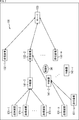
- the communication system 11 using the LPWA communication shown in FIG. 1 includes transmitting devices 31-1 to 31-q, receiving devices 32-1 to 32-m, and a server 33.
- transmitting devices 31-1 to 31-q and the receiving devices 32-1 to 32-m are simply referred to as the transmitting device 31 and the receiving device 32 unless it is necessary to distinguish them from each other.
- the configuration will be referred to in the same manner.
- the transmission device 31 is arranged with various sensors (not shown) provided in various environments, or is carried by a predetermined user or the like, and the sensors detected by the sensors (not shown) in each environment.
- the data is acquired and transmitted to the server 33 via the receiving device 32.
- the operation of the receiving device 32 is controlled by the server 33, and the sensor data transmitted from the transmitting device 31 is received and transmitted to the server 33.
- the server 33 controls the operation of the receiving device 32, receives the sensor data transmitted from the transmitting device 31 via the receiving device 32, and executes various application programs according to the received sensor data.
- the sensor data is transmitted between the transmitter 31 and the receiver 32 by LPWA communication.
- the sensor data is unidirectionally transmitted from the transmitter 31 to the receiver 32.
- the plurality of transmitters 31 obtain the transmission time and the transmission frequency at which the sensor data is transmitted and the transmission frequency by a predetermined calculation using, for example, an identifier for individually identifying the transmission device 31, And transmitting the sensor data toward the receiving device 32 at the transmission frequency.
- the receiving device 32 acquires an identifier for each transmitting device 31 which is supposed to receive sensor data from the server 33 in advance.
- the reception device 32 calculates the transmission time and the transmission frequency at which the sensor data of each transmission device 31 is transmitted, by the same calculation as the calculation in the transmission device 31, based on the acquired identifier. Then, the receiving device 32 receives the calculated transmission time and the sensor data transmitted at the transmission frequency.
- the transmission device 31 and the reception device 32 send and receive sensor data at the transmission time and the transmission frequency calculated based on the identifier of the transmission device 31.
- the transmitting device 31 need only transmit the sensor data to the receiving device 32 in one direction, so that communication with low power consumption can be realized.
- a relay device 141 is configured between the transmission device 131 and the reception device 132, and the transmission device 131 and the reception device 132 are provided via the relay device 141. It is configured to send and receive.
- the communication system 101 of FIG. 2 includes transmitting devices 131 to 131-q, receiving devices 132-1 to 132-m, a server 133, and relays 141-1 and 141-2.
- the basic functions of the transmission device 131, the reception device 132, and the server 133 are the same as those of the transmission device 31, the reception device 32, and the server 33 in FIG. 1.
- the repeater 141 receives the transmission data including the sensor data in the payload transmitted from the transmission device 131, and transmits it to the reception device 132.
- the transmission device 131 has a configuration such as an alarm buzzer for notifying the occurrence of an emergency situation, for example. More specifically, the transmission device 131 as an alarm buzzer includes an operation unit that is operated in an emergency. When the operation unit is operated, the GPS unit included in the transmission unit 131 obtains information on the current position, and the emergency situation occurs. Together with the information notifying that the occurrence of the above is transmitted to the receiving device 132 via the repeater 141.
- the receiving device 132 outputs information to the server 133 when the information notifying the occurrence of an emergency including the position information is acquired.
- the server 133 notifies the police or security company together with the position information based on the information from the receiving device 132 that notifies the occurrence of an emergency.
- the communication system 101 of the present disclosure is supposed to be a crime prevention system as a whole.
- the repeater 141 is provided in a space that can avoid a communication failure due to an obstacle 34 such as a mountain area, and is not a large-sized configuration using commercial power as in the general receiving apparatus 132, but is, for example, , It can be moved by natural energy such as solar cells at the mountain tops in mountainous areas and small capacity electric power such as batteries.
- the repeater 141 needs to be smaller and have lower power consumption than the configuration of the receiving device 132.
- the receiving side device changes the transmitting time, the transmitting frequency, and the like by the number of transmitting devices 131 so that various transmitting devices 131 can transmit the same. It becomes necessary to prepare for the reception of the transmission signal of, and the processing load and the processing time related to the reception increase.
- the communication system 101 of the present disclosure assumes a crime prevention system as a whole.
- the individual transmission time and transmission frequency patterns of the transmission devices 131 are set using the identifiers that identify the transmission devices 131, so that even if the number of transmission devices 131 increases, If the transmission time to be changed and the number of patterns of the transmission frequency do not increase, the processing load and processing time on the receiving side device can be suppressed.
- the transmission device 131 is divided into a plurality of groups, an identifier is set for each group, and a transmission time and a transmission frequency are set using the identifier for each group. By doing so, the processing load and processing time on the receiving side are reduced.
- a plurality of group-based identifiers should be set for one group. May be. However, since a plurality of transmitting devices 131 in the same group have a very low probability of simultaneous transmission processing and causing a collision, a plurality of identifiers of a number sufficiently smaller than the number of transmitting devices 131 forming the group are used. Should be set. Further, in the case where the number of transmitting devices 131 configuring a group is not so large, the possibility of collision is low, and therefore, only one identifier may be used for each group.
- the header of the transmission data normally stores the identifier of each individual transmission device 131, it is possible to identify which transmission device 131 transmitted the data.
- the identifier for each group is used, the identifier for each group is stored instead of the individual identifier of the transmitting device 131, so that the group to which the transmitting device 131 that has transmitted the transmission data belongs can be specified. However, it becomes impossible to specify which transmission device 131 is.
- the identifier for each group is stored in the header, by storing the identifier of the transmission device 131 in a part of the payload, it is possible to specify the transmission device 131 that is the transmission source of the transmission data.
- the processing load and the processing time related to the reception processing in the repeater 141 will be several hundredths.
- the repeater 141 can realize low power consumption. For example, by using a small amount of electric power such as a solar power generation system or a battery, the relay 141 can be relayed even in an environment where commercial power cannot be supplied. It becomes possible to realize the function as a container.
- the transmission device 131 When using the identifier for each group, it is possible to specify the transmission device 131 that is the transmission source by storing the individual identifier in the payload of the transmission data.
- the transmission device 131 includes a control unit 151, a GPS 152, an operation unit 153, a communication unit 154, a storage unit 155, a drive 156, a removable storage unit 157, and a bus 158.
- the control unit 151, the GPS 152, the operation unit 153, the communication unit 154, the storage unit 155, the drive 156, and the removable storage unit 157 are connected via a bus 158, and can exchange data and programs with each other. Has been done.
- the control unit 151 includes a processor and a memory, and controls the overall operation of the transmission device 131.
- the control unit 151 also generates transmission data based on the position information acquired by the communication unit GPS 152 when the operation unit 153 that is operated when it is necessary to notify the occurrence of an emergency is operated. Then, as described with reference to FIG. 3, the control unit 151 determines the transmission time and the transmission frequency based on the special ID that is the identifier for identifying the group, controls the communication unit 154, and transmits the transmission data. To do.
- the transmission device 131 of the present disclosure is intended to function as a so-called alarm buzzer for the purpose of notifying the occurrence of an emergency, it is possible to transmit transmission data for purposes other than emergency. You can also
- transmission intended for the occurrence of an emergency will be called special transmission, and other transmissions will be called normal transmission.
- a GPS (Global Positioning System) 152 receives a signal from a satellite (not shown), acquires time information together with position information, and outputs the time information to the control unit 151.
- the operation unit 153 is composed of, for example, a string or a button that is pulled out in an emergency, and outputs a signal according to the operation to the control unit 151. That is, the control unit 151 recognizes that an emergency has occurred when the operation unit 153 is operated, performs special transmission at this time, and performs normal transmission at other times.
- the communication unit 154 is controlled by the control unit 151, generates transmission data including sensor data including position information by LPWA communication, and transmits the transmission data to the reception device 132 or the relay device 141.
- the storage unit 155 includes an HDD (Hard Disk Drive), an SSD (Solid State Drive), or a semiconductor memory, and is controlled by the control unit 151 to write or read various data and programs.
- a unique identifier (LPWA_ID) for identifying the transmitting device 131 is stored.
- the drive 156 reads/writes data from/to the removable storage unit 157 such as a semiconductor memory.
- the identifier of the transmission device 131 may be stored in the removable storage unit 157.
- the repeater 141 includes a control unit 171, a GPS 172, an operation unit 173, a communication unit 174, a storage unit 175, a drive 176, a removable storage unit 177, and a bus 178.
- the control unit 171, the GPS 172, the operation unit 173, the communication unit 174, the storage unit 175, the drive 176, and the removable storage unit 177 are connected via a bus 178, and can exchange data and programs with each other. Has been done.
- the control unit 171 includes a processor and a memory, and controls the entire operation of the repeater 141.
- control unit 171 acquires the identifier (LPWA_ID) of the transmitting device 131 that transmits the transmission data and the group identifier (special ID) of the transmitting device 131 from the receiving device 132 or the server 133 in advance. There is.
- the control unit 171 preliminarily determines, for each of the LPWA_ID and the special ID, which transmitter 131 or which group of transmitters 131 is transmitting transmission data at which time and at which transmission frequency. It is obtained by the same calculation as the calculation method in, and is stored as a list.
- the control unit 171 identifies the reception time associated with the transmission device 131 or the group of the transmission device 131 based on the stored list, and reads the information of the corresponding transmission frequency.
- control unit 171 controls the communication unit 174 to receive the transmission data transmitted at the corresponding transmission frequency.
- control unit 171 controls the communication unit 174 to cause the transmission data transmitted from the transmission device 131 to be transmitted to the server 133 by general LPWA communication.
- the receiving device 132 functions as a transmitting device in LPWA communication.
- a GPS (Global Positioning System) 172 receives a signal from a satellite (not shown), acquires time information together with position information, and outputs the time information to the control unit 171.
- the operation unit 173 is composed of, for example, a keyboard and operation buttons, and outputs a signal according to the operation to the control unit 171.
- the communication unit 174 is controlled by the control unit 171 and receives the transmission data transmitted from the transmission device 131 and transmits it to the reception device 132 by LPWA communication.
- the storage unit 175 includes an HDD (Hard Disk Drive), an SSD (Solid State Drive), a semiconductor memory, or the like, and is controlled by the control unit 151 to write or read various data and programs.
- the storage unit 175 stores an identifier (LPWA_ID) that individually identifies the transmission device 131 that transmits the transmission data and an identifier (special ID) that identifies the group to which the transmission device 131 belongs, and based on the identifier. Then, the reception time and the transmission frequency information calculated by the same method as the method calculated by the transmitter 131 are stored.
- the drive 176 reads/writes data from/to a removable storage unit 177 such as a semiconductor memory.
- the transmission device 131 includes a normal transmission parameter storage unit 201, a special transmission parameter storage unit 202, a transmission parameter selection unit 203, a transmission time determination unit 204, a selection unit 205, an LPWA_ID storage unit 206, a special ID determination unit 207, and an ID selection unit 208. , And a transmission control unit 209.
- the normal transmission parameter storage unit 201 stores normal transmission parameters that are transmission parameters used when the transmission device 131 transmits transmission data in normal transmission.
- the special transmission parameter storage unit 202 stores the special transmission parameter which is a transmission parameter used by the transmission device 131 at an emergency, that is, when the operation unit 153 is operated by the user.
- the same transmission data is continuously transmitted and received multiple times while switching channels at a specified timing (frame delay time) within a specified interval (slot period), and is repeated at a specified interval (burst interval). Be done.
- the transmission parameter defines the specified period (slot period), the specified timing (frame delay time) within the specified period, and the channel to be switched in this LPWA communication.
- the selection unit 205 outputs a selection signal indicating that an emergency has occurred to the transmission parameter selection unit 203 and the ID selection unit 208, depending on whether or not the operation unit 153 is operated.
- the transmission parameter selection unit 203 reads out the normal transmission parameter stored in the normal transmission parameter storage unit 201 and transmits the transmission time determination unit 204. Output to.
- the transmission parameter selection unit 203 sets the special transmission parameter stored in the special transmission parameter storage unit 202. It is selected and supplied to the transmission time determination unit 204.
- the transmission time determination unit 204 determines the transmission time based on the normal transmission parameter or the special transmission parameter selected by the transmission parameter selection unit 203 and the current time information acquired by the GPS 152, and the special ID determination unit 207 and the transmission control unit 209. At this time, the transmission time determination unit 204 determines the transmission time by the calculation used when determining the transmission time in the LPWA communication.
- the LPWA_ID storage unit 206 stores the LPWA_ID, which is a unique identifier of the transmission device 131, and supplies the LPWA_ID to the special ID determination unit 207, the ID selection unit 208, and the transmission control unit 209.
- the LPWA_ID storage unit 206 has a configuration corresponding to the storage unit 155.
- the special ID determination unit 207 determines, based on the transmission time supplied from the transmission time determination unit 204 and the LPWA_ID stored in the LPWA_ID storage unit 206, the transmission device 131 when the transmission device 131 is set to a predetermined number of groups.
- a special ID which is the identifier of the group to which is belongs, is calculated and output to the ID selection unit 208.
- the detailed configuration of the special ID determination unit 207 will be described later with reference to FIG.
- the ID selection unit 208 selects the LPWA_ID stored in the LPWA_ID storage unit 206 and outputs it as the Modulation ID to the transmission control unit 209. To do.
- the ID selection unit 208 selects the special ID determined by the special ID determination unit 207 and performs transmission control as Modulation ID. It is output to the unit 209.
- the transmission control unit 209 controls the communication unit 154 based on the transmission time information and the Modulation ID to store the position information acquired by the GPS 152 in the payload and transmit the position information to the repeater 141 or the reception device 132.
- the transmission control unit 209 generates transmission data in the format shown in the upper part of FIG. 7, and causes the communication unit 154 to transmit it.
- the transmission control unit 209 stores the Modulation ID including the special ID in the 32-bit header portion, further stores the special ID in 40 bits of the 128-bit payload, and acquires the GPS 152 using the remaining 88 bits.
- the position information is stored and a 24-bit CRC part is added to generate transmission data.
- the transmission control unit 209 when the Modulation ID is LPWA_ID, the transmission control unit 209 generates transmission data in the format shown in the lower part of FIG. 7, and causes the communication unit 154 to transmit it.
- the transmission control unit 209 stores LPWA_ID in a 32-bit header portion, further stores the position information acquired by the GPS 152 in a 128-bit payload, and further adds a 24-bit CRC portion to generate transmission data. To do.
- the special ID determination unit 207 includes LFSRs 221 and 222 and PRN 223.
- LFSRs Linear Feedback Shift Registers 221 and 222 calculate the LFSR polynomial of the number of bits according to a predetermined number set as a special ID, with LPWA_ID and transmission time as initial values, respectively, and calculate the operation result as PRN (pseudo (Random number generator) 223.
- the pseudo random number generation unit 223 generates a pseudo random number (PRN) based on the calculation results of the LFSRs 221 and 222, thereby generating a value that serves as an index of a predetermined number of special IDs.
- PRN pseudo random number
- the special ID determination unit 207 outputs an index that identifies any of the predetermined number of special IDs based on the LPWA_ID, time information, and information on the number of special IDs set for the group to which the special ID belongs. Therefore, when selecting the special ID, the ID selecting unit 208 selects the special ID that is set in advance in association with the index based on the index supplied from the special ID determining unit 207.
- the time information may be, for example, a parameter for setting different special IDs when special transmission is performed by the plurality of transmitting devices 131, such as the last transmission completion time and the operation.
- the time when the section 153 is operated may be sufficient.
- the transmission device 131 allocates eight special IDs to one group based on the information of LPWA_ID and time information.
- the number of special IDs set in one group needs to be set in accordance with the probability that the transmission devices 131 that specially transmit at the same time among the transmission devices 131 set in one group can occur.
- the maximum value that may be needed at the same time may be set to a number that covers the maximum value.
- the transmitting device 131 adds the special ID to the header and generates the transmission data in the format in which the LPWA_ID and the position information are stored in the payload to generate the relay 141 when an emergency occurs. Send to.
- the repeater 141 includes a reception time list storage unit 241, a time information acquisition unit 242, a reception control unit 243, a special ID processing unit 244, and a transmission control unit 245.
- the reception time list storage unit 241 stores the information of the reception time list for receiving the transmission data from the transmission device 131 allocated for each special ID or LPWA_ID of all the transmission devices 131 to which the transmission data may be transmitted. I remember.
- reception time can be obtained based on the transmission parameters shared by the transmission device 131, the relay 141 and the reception device 132, and the special ID or LPWA_ID of the transmission device 131.
- the relay device 141 calculates the reception time at the timing when the special ID or LPWA_ID of the transmission device 131 that may transmit the transmission data is acquired, and stores the reception time in the reception time list storage unit 241. Good.
- the special ID or LPWA_ID of the transmission device 131 that may have transmission data may be stored in the storage unit 175 at the time of manufacture, or may be supplied from the server 133 via the reception device 132 at a predetermined timing. It may be done.
- the transmission device 131 transmits the LPWA_ID at a timing determined by the shared transmission parameter. Then, the repeater 141 acquires this LPWA_ID as an identifier of the transmission device 131 that may transmit the transmission data, calculates the reception time and the transmission frequency, and registers them in the reception time list storage unit 241. You may do so.
- the repeater 141 repeats the process of changing the transmission frequency according to the reception time based on the special ID or LPWA_ID of the transmission device 131, when the number of target transmission devices 131 increases, that is, the special ID If the number of or LPWA_ID increases, it becomes necessary to frequently change the transmission frequency according to the reception time, which increases the processing load.
- the communication load is limited to the special ID to reduce the frequency of changing the transmission frequency according to the reception time. It is possible to reduce the size of the repeater 141, and it is possible to reduce the size and weight of the device of the repeater 141 and reduce the power consumption.
- the time information acquisition unit 242 acquires the current time information supplied from the GPS 172 and supplies it to the reception control unit 243 and the transmission control unit 245.
- the reception control unit 243 transmits from one of the transmission devices 131 based on the reception time information stored in the reception time list storage unit 241 and the current time information supplied from the time information acquisition unit 242. It is determined whether it is the reception time of the transmitted data.
- the reception control unit 243 controls the communication unit 174 according to the special ID or the Modulation ID corresponding to the LPWA_ID to cause the transmission data to be received and to be supplied to the special ID processing unit 244.
- the special ID processing unit 244 determines whether the Modulation ID included in the header of the received transmission data is a normal LPWA_ID or a special ID, and if it is the special ID, that is, the special transmission, the payload Extract the LPWA_ID and location information stored in. Then, the special ID processing unit 244 stores the extracted LPWA_ID in the header, generates the transmission data of the relay device 141 in the format in which the position information is stored in the payload, and outputs the transmission data to the transmission control unit 245.
- the special ID processing unit 244 uses the received transmission data as it is as the transmission data of the relay device 141, and transmits the transmission control unit. Output to 245.
- the transmission control unit 245 controls the communication unit 174 to relay the transmission data transmitted from the transmission device 131 and transmit it to the reception device 132 as transmission data of the relay device 141 by normal LPWA communication.
- step S11 the selection unit 205 recognizes the operation state of the operation unit 153, determines whether or not any trigger is received, and repeats the same processing until the trigger is received.
- the trigger mentioned here indicates, for example, an operation indicating that an emergency has occurred, or whether or not the user has voluntarily operated to transmit position information as an ordinary operation instead of an emergency. It is a thing.
- step S11 is repeated until some operation is performed.
- step S11 If it is determined in step S11 that the trigger is activated, the process proceeds to step S12.
- step S12 the selection unit 205 is a trigger indicating that an emergency has occurred, and determines whether it is a special transmission. If it is special transmission in step S12, the process proceeds to step S13.
- step S13 the selection unit 205 notifies the transmission parameter selection unit 203 and the ID selection unit 208 of information indicating special transmission.
- the transmission parameter selection unit 203 reads out the special transmission parameter stored in the special transmission parameter storage unit 202 and outputs it to the transmission time determination unit 204.
- step S14 the transmission time determination unit 204 calculates the transmission time by the calculation method in the LPWA communication based on the current time information acquired by the GPS 152 and the special transmission parameter, and the special ID determination unit 207 and the transmission control. It is output to the unit 209.
- step S15 the special ID determination unit 207 determines whether the special transmission time is the last transmission completion time or time information such as time information when the operation unit 153 is operated, LPWA_ID in the LPWA_ID storage unit 206, and the number of special IDs. The ID is determined and output to the ID selection unit 208.
- step S16 the ID selection unit 208 acquires the special ID determined by the special ID determination unit 207 and outputs it as the Modulation ID to the transmission control unit 209.
- step S17 the transmission control unit 209 uses ModulationID, which is a special ID, as a header, and stores the LPWA_ID stored in the LPWA_ID storage unit 206 in the payload to generate transmission data.
- ModulationID which is a special ID, as a header
- step S18 the transmission control unit 209 acquires position information from the GPS 152 and stores it in the payload along with LPWA_ID to complete the transmission data.
- step S19 the transmission control unit 209 acquires time information from the GPS 152, determines whether the transmission time has come, and repeats the same processing until the transmission time comes. Then, when the transmission time has come in step S19, the process proceeds to step S20.
- step S20 the transmission control unit 209 controls the communication unit 154 to transmit the transmission data to the relay device 141 or the reception device 132 at the transmission frequency corresponding to ModulationID.
- step S21 it is determined whether or not the end of the transmission process is instructed. If it is determined that the end is not instructed, the process returns to step S11, and the subsequent processes are repeated. If it is determined in step S21 that the end is instructed, the process ends.
- step S12 If it is determined in step S12 that the transmission is not normal transmission but normal transmission, the process proceeds to step S22.
- step S22 the transmission parameter selection unit 203 reads out the normal transmission parameters stored in the normal transmission parameter storage unit 201 and outputs them to the transmission time determination unit 204.
- step S23 the transmission time determination unit 204 calculates the transmission time by the calculation method in the LPWA communication based on the current time information acquired by the GPS 152 and the normal transmission parameter, and the transmission control unit 209 together with the normal transmission parameter. Output to.
- step S24 the transmission control unit 209 acquires the LPWA_ID stored in the LPWA_ID storage unit 206.
- step S25 the transmission control unit 209 generates transmission data in a format with LPWA_ID as a header.
- the transmission data in the format in which the LPWA_ID is used as the header and the position information is stored in the payload is transmitted at the transmission frequency corresponding to the Modulation ID including the LPWA_ID.
- the special ID is set in ModulationID and stored in the header, and further, the LPWA_ID unique to the transmitting device 131 and the position information that is sensing data are stored in the payload. It becomes possible to transmit the transmitted data.
- step S41 the reception control unit 243 searches the reception time information stored in the reception time list storage unit 241 based on the current time information supplied from the time information acquisition unit 242, and the reception time is reached. Whether or not it is determined, and similar processing is repeated until the reception time.
- step S41 If it is determined that the reception time has come in step S41, the process proceeds to step S42.
- step S42 the reception control unit 243 controls the reception frequency of the communication unit 174 based on the special ID recorded in the reception time list storage unit 241 in association with the reception time or the Modulation ID formed of LPWA_ID. , And makes the special ID processing section 244 output the received transmission data.
- step S43 the special ID processing unit 244 determines whether the special ID, that is, the special transmission, is based on the Modulation ID stored in the header of the received transmission data. If it is the special ID, that is, if it is the special transmission, the process proceeds to step S44.
- step S44 the special ID processing unit 244 reads LPWA_ID from the payload of the received transmission data.
- step S45 the special ID processing unit 244 uses the read LPDA_ID as a header and generates the transmission data of the relay device 141 in the format for normal LPDA communication in which the positional information transmitted in the payload is stored, and the transmission control unit Output to 245.
- step S46 the transmission control unit 245 determines whether or not the transmission time in the normal LPWA communication to the reception device 132 has arrived, based on the current time information supplied from the time information acquisition unit 242, and the transmission time The same process is repeated until.
- step S46 determines whether the transmission time has come. If it is determined in step S46 that the transmission time has come, the process proceeds to step S47.
- step S47 the transmission control unit 245 controls the communication unit 174 based on the ModulationID that is the LPWA_ID that serves as the header of the transmission data, and transmits the transmission data to the receiving device 132 by normal LPWA communication.
- step S48 it is determined whether or not the end of the relay process is instructed, and if it is determined that the end is not instructed, the process returns to step S41, and the processes after that are repeated. If the end is instructed in step S48, the process ends.
- step S43 if the header is not the special ID, that is, the header is composed of LPWA_ID and is a normal transmission, the process proceeds to step S49.
- step S49 the special ID processing unit 244 uses the received transmission data transmitted from the transmission device 131 as it is as the transmission data of the relay device 141, and the process proceeds to step S46. Then, by the processing of steps S46 to S48, the transmission data is transmitted to the reception device 132 by normal LPWA communication. Through this series of processing, the transmission data transmitted from the transmission device 131 is relayed by the relay device 141 and transmitted to the reception device 132.
- the relay process in the relay 141 has been described, but the receiving device 132 can also receive the transmission data by the same process.
- the LPWA_ID stored in the payload is read and the same as the transmission data received in the normal transmission. Is output to the server 133 in association with the position information.
- the special ID will be randomly selected based on the transmission time, it is possible to suppress the occurrence of collision and select the maximum number of simultaneous communications according to the application.
- the range of the transmission time in the transmission device 131 can be specified, so that it is possible to specify that the special IDs that are a plurality of group IDs are in the adjacent transmission time range.
- the relay processing time on the relay device 141 side does not significantly increase.
- Example of executing by software By the way, the series of processes described above can be executed by hardware, but can also be executed by software. When a series of processes is executed by software, a program that constitutes the software can execute various functions by installing a computer in which dedicated hardware is installed or various programs. It is installed from a recording medium into a possible general-purpose computer or the like.
- FIG. 12 shows a configuration example of a general-purpose computer.
- This personal computer has a built-in CPU (Central Processing Unit) 1001.
- An input/output interface 1005 is connected to the CPU 1001 via a bus 1004.
- a ROM (Read Only Memory) 1002 and a RAM (Random Access Memory) 1003 are connected to the bus 1004.
- the input/output interface 1005 includes an input unit 1006 configured by an input device such as a keyboard and a mouse for inputting operation commands by a user, an output unit 1007 for outputting a processing operation screen and an image of a processing result to a display device, programs and various data.
- a storage unit 1008 including a hard disk drive for storing the data, a LAN (Local Area Network) adapter, and the like are connected to a communication unit 1009 that executes communication processing via a network typified by the Internet. Also, magnetic disks (including flexible disks), optical disks (including CD-ROM (Compact Disc-Read Only Memory), DVD (Digital Versatile Disc)), magneto-optical disks (including MD (Mini Disc)), or semiconductors.
- a drive 1010 for reading and writing data is connected to a removable storage medium 1011 such as a memory.
- the CPU 1001 is read from a program stored in the ROM 1002 or a removable storage medium 1011 such as a magnetic disk, an optical disk, a magneto-optical disk, or a semiconductor memory, installed in the storage unit 1008, and loaded into the RAM 1003 from the storage unit 1008. Various processes are executed according to the program.
- the RAM 1003 also appropriately stores data necessary for the CPU 1001 to execute various processes.
- the CPU 1001 loads the program stored in the storage unit 1008 into the RAM 1003 via the input/output interface 1005 and the bus 1004 and executes the program, thereby performing the above-described series of operations. Is processed.
- the program executed by the computer (CPU 1001) can be provided, for example, by recording it on a removable storage medium 1011 as a package medium or the like.
- the program can be provided via a wired or wireless transmission medium such as a local area network, the Internet, or digital satellite broadcasting.
- the program can be installed in the storage unit 1008 via the input/output interface 1005 by mounting the removable storage medium 1011 in the drive 1010. Further, the program can be received by the communication unit 1009 via a wired or wireless transmission medium and installed in the storage unit 1008. In addition, the program can be installed in advance in the ROM 1002 or the storage unit 1008.
- the program executed by the computer may be a program in which processing is performed in time series in the order described in the present specification, or in parallel or at a necessary timing such as when a call is made. It may be a program for processing.
- the CPU 1001 in FIG. 12 realizes the functions of the control unit 151 in FIG. 4 and the control unit 171 in FIG.
- the system means a set of a plurality of constituent elements (devices, modules (parts), etc.), and it does not matter whether or not all the constituent elements are in the same housing. Therefore, a plurality of devices housed in separate housings and connected via a network, and one device housing a plurality of modules in one housing are all systems. ..
- the present disclosure may have a configuration of cloud computing in which one function is shared by a plurality of devices via a network and jointly processes.
- each step described in the above flow chart can be executed by one device or shared by a plurality of devices.
- one step includes a plurality of processes
- the plurality of processes included in the one step can be executed by one device or shared by a plurality of devices.
- ⁇ 1> Transmission control for controlling transmission of communication data to the receiving device at a communication time and a communication frequency based on own individual identification information and communication interval information shared by the receiving device and itself.
- Section, In a specific communication when the transmission control unit divides a plurality of transmission devices including the self into a plurality of groups, the group identification information set for the group to which the self belongs and the self and the reception device. A transmitting device that controls transmission of communication data to the receiving device at the communication time and the communication frequency based on the communication interval information shared by.
- the transmission control unit generates the communication data in which a payload stores the individual identification information of itself, and controls transmission to the receiving device. apparatus.
- a group identification information determining unit that determines the group identification information based on the individual identification information, the time information, and the number of the group identification information set in the own group is further included.
- the group identification information determination unit is a pseudo-random number of bits corresponding to the number of the group identification information when an LFSR (Linear Feedback Shift Register) is used with the individual identification information and the time information as initial values.
- LFSR Linear Feedback Shift Register
- the said time information is a transmission apparatus as described in ⁇ 3> containing the time when the said specific communication of the last time was completed, or the time when the said operation part was operated.
- the transmission device according to ⁇ 5> wherein when the operation unit is operated, the transmission control unit transmits the communication data to the reception device by the specific communication.
- the current time information is the time information acquired by a GPS (Global Positioning System) device.
- the transmission device wherein the payload of the communication data stores position information acquired by the GPS (Global Positioning System) device.
- a transmitting method of a transmitting device including a unit When the transmission control unit divides a plurality of transmission devices including the self into a plurality of groups in a specific communication, the group identification information set in the group to which the self belongs and the self and the reception device.
- a reception control unit that controls reception of communication data at a communication time and a communication frequency based on individual identification information of a plurality of transmitters and communication interval information shared with the transmitters. Prepare, When dividing the plurality of transmitting devices into a plurality of groups in a specific communication, the reception control unit shares the group identification information set in the group to which the transmitting device belongs with the transmitting device itself. A receiving device that controls the reception of communication data at the communication time and the communication frequency based on the communication interval information.
- the group identification information is determined based on individual identification information of the transmitting device that has transmitted the communication data, time information, and the number of the group identification information set in its own group. Alternatively, the receiving device according to ⁇ 12>.
- the group identification information is a pseudo random number having a bit number corresponding to the number of the group identification information when an LFSR (Linear Feedback Shift Register) is used with the individual identification information and the time information as initial values.
- the receiving device according to ⁇ 13> which is determined by using the receiving device.
- ⁇ 15> The reception device according to any one of ⁇ 11> to ⁇ 14>, wherein the communication time is determined based on the communication interval information and the current time information.
- ⁇ 16> The reception device according to ⁇ 15>, wherein the current time information is time information acquired by a GPS (Global Positioning System) device.
- the payload of the communication data stores position information acquired by a GPS (Global Positioning System) device of the transmission device.
- the communication data in which the position information of the transmission device is stored in a payload is transmitted.
- the receiving device according to any one of ⁇ 11> to ⁇ 17>, which is communication performed.
- the reception device according to any one of ⁇ 11> to ⁇ 18>, further including a transmission control unit that relays communication data received by the reception control unit and transmits the communication data to another reception device.
- a reception control unit that controls reception of communication data at a communication time and a communication frequency based on individual identification information of a plurality of transmitters and communication interval information shared with the transmitters.
- 101 communication system 131 transmitting device, 132 receiving device, 133 cloud server, 141 repeater, 151 control unit, 152 GPS, 153 operating unit, 154 communication unit, 155 storage unit, 156 drive, 157 removable storage unit, 171 control unit , 172 GPS, 173 operation section, 174 communication section, 175 storage section, 176 drive, 177 removable storage section, 201 normal transmission parameter storage section, 202 special transmission parameter section, 203 transmission parameter selection section, 204 transmission time determination section, 205 Selection unit, 206 LPWA_ID storage unit, 207 Special ID determination unit, 208 ID selector, 209 transmission control unit, 221,222 LFSR, 223 PRN, 241 reception time list, 242 time information acquisition unit, 243 reception control unit, 244 special ID processing unit, 245 transmission control unit
Landscapes
- Engineering & Computer Science (AREA)
- Computer Networks & Wireless Communication (AREA)
- Signal Processing (AREA)
- Multimedia (AREA)
- Business, Economics & Management (AREA)
- Health & Medical Sciences (AREA)
- Emergency Management (AREA)
- Environmental & Geological Engineering (AREA)
- Public Health (AREA)
- Mobile Radio Communication Systems (AREA)
Abstract
本開示は、LPWA(Low Power Wide Area)通信における受信側の処理負荷を低減できるようにする送信装置および送信方法、並びに受信装置および受信方法に関する。 複数の送信装置を複数のグループに分割し、個別の識別情報に代えて、グループに設定されるグループ識別情報と、送信装置と受信装置とで共有している通信間隔情報とに基づいた、通信時刻、および通信周波数で通信データを送受信する。本開示は、LPWA通信システムに適用することができる。
Description
本開示は、送信装置および送信方法、並びに受信装置および受信方法に関し、特に、LPWA(Low Power Wide Area)通信における受信側の処理負荷を低減できるようにした送信装置および送信方法、並びに受信装置および受信方法に関する。
LPWA(Low Power Wide Area)通信を用いた通信技術が提案されている(特許文献1参照)。
LPWA通信は、低ビットレートによる少量のPayloadデータ(100ビット前後)を、IoT端末(送信装置)からIoTゲートウェイ(受信装置)に一方向に送受信する通信であるため、LPWA通信を行なうIoT端末(送信器)においては低消費電力での通信を実現することができる。
上述したLPWA通信においては、送信装置からの通信をカバーできる範囲を広くするには、受信装置を広範囲に設置する必要がある。
特に、山間部などの電波が届き難い地域においては、サーバ装置にアクセスできるような環境も整っていないので、中継器などを設置することで、通信可能な受信装置に対して受信した送信装置からの信号を中継することで、範囲をカバーすることが考えられる。
LPWA通信においては、送信装置における低消費電力を実現させるため、受信装置においては、多くの送信装置からの通信を、タイミングや周波数を変えて、個別に受け付ける必要があり、送信装置の数が多くなる程、受信に要する処理負荷が高くなり、それに伴って、装置構成が大型化し、消費電力も大きくなる。
一方、山間部などにおいては、商用電力の供給を受けることができず、太陽電池などの限られた電力供給しか受けられない環境であることが多い。
このため、送信装置の処理負荷を低減させることを目的としたLPWA通信において、多くの送信装置からの通信を受け付けて受信装置に中継する中継器を実現するには、LPWA通信における受信側の処理負荷を低減させ、より低消費電力の中継器を実現する必要がある。
本開示は、このような状況に鑑みてなされたものであり、特に、LPWA通信において、受信に係る処理負荷を低減するものである。
本開示の第1の側面の送信装置は、自らの個体識別情報と、前記自らと受信装置とで共有している通信間隔情報とに基づいた、通信時刻、および通信周波数で通信データの前記受信装置への送信を制御する送信制御部を備え、前記送信制御部は、特定の通信において、前記自らを含めた複数の送信装置を複数のグループに分割したとき、前記自らが属するグループに設定されるグループ識別情報と、前記自らと前記受信装置とで共有している通信間隔情報とに基づいた、前記通信時刻、および前記通信周波数で通信データの前記受信装置への送信を制御する送信装置である。
本開示の第1の側面の送信方法は、送信装置の構成に対応する。
本開示の第1の側面においては、自らの個体識別情報と、前記自らと受信装置とで共有している通信間隔情報とに基づいた、通信時刻、および通信周波数で通信データの前記受信装置への送信が制御され、特定の通信において、前記自らを含めた複数の送信装置を複数のグループに分割したとき、前記自らが属するグループに設定されるグループ識別情報と、前記自らと前記受信装置とで共有している通信間隔情報とに基づいた、前記通信時刻、および前記通信周波数で通信データの前記受信装置への送信が制御される。
本開示の第2の側面の受信装置は、複数の送信装置の個体識別情報と、前記送信装置と自らとで共有している通信間隔情報とに基づいた、通信時刻、および通信周波数で通信データの受信を制御する受信制御部を備え、前記受信制御部は、特定の通信において、前記複数の前記送信装置を複数のグループに分割したとき、前記送信装置が属するグループに設定されるグループ識別情報と、前記送信装置と自らとで共有している通信間隔情報とに基づいた、前記通信時刻、および前記通信周波数で通信データの受信を制御する受信装置である。
本開示の第2の側面の受信方法は、受信装置の構成に対応する。
本開示の第2の側面においては、複数の送信装置の個体識別情報と、前記送信装置と自らとで共有している通信間隔情報とに基づいた、通信時刻、および通信周波数で通信データの受信が制御され、特定の通信において、前記複数の前記送信装置を複数のグループに分割したとき、前記送信装置が属するグループに設定されるグループ識別情報と、前記送信装置と自らとで共有している通信間隔情報とに基づいた、前記通信時刻、および前記通信周波数で通信データの受信が制御される。
以下に添付図面を参照しながら、本開示の好適な実施の形態について詳細に説明する。なお、本明細書及び図面において、実質的に同一の機能構成を有する構成要素については、同一の符号を付することにより重複説明を省略する。
以下、本技術を実施するための形態について説明する。説明は以下の順序で行う。
1.LPWA通信を用いた片方向通信システムの概要
2.本開示の概要
3.送信装置のハードウェア構成例
4.中継器のハードウェア構成例
5.送信装置により実現される機能の構成例
6.中継器により実現される機能の構成例
7.送信装置による送信処理
8.中継器による中継処理
9.ソフトウェアにより実行させる例
1.LPWA通信を用いた片方向通信システムの概要
2.本開示の概要
3.送信装置のハードウェア構成例
4.中継器のハードウェア構成例
5.送信装置により実現される機能の構成例
6.中継器により実現される機能の構成例
7.送信装置による送信処理
8.中継器による中継処理
9.ソフトウェアにより実行させる例
<<1.LPWA通信を用いた片方向通信システムの概要>>
図1を参照して、LPWA(Low Power Wide Area)通信を用いた片方向通信システムの概要について説明する。
図1を参照して、LPWA(Low Power Wide Area)通信を用いた片方向通信システムの概要について説明する。
図1のLPWA通信を用いた通信システム11は、送信装置31-1乃至31-q、受信装置32-1乃至32-m、およびサーバ33より構成される。
尚、送信装置31-1乃至31-q、および受信装置32-1乃至32-mは、それぞれを特に区別する必要がない場合、単に送信装置31、および受信装置32と称するものとし、その他の構成についても同様に称する。
送信装置31は、様々な環境に設けられる各種の図示せぬセンサと共に配置される、または、所定のユーザ等に所持されるものであり、それぞれの環境において、図示せぬセンサにより検出されたセンサデータを取得して、受信装置32を介してサーバ33に送信する。
受信装置32は、サーバ33により動作が制御され、送信装置31より送信されるセンサデータを受信し、サーバ33に送信する。
サーバ33は、受信装置32の動作を制御するとともに、受信装置32を介して送信装置31より送信されてくるセンサデータを受信し、受信したセンサデータに応じて各種のアプリケーションプログラムを実行させる。
送信装置31と受信装置32とは、LPWA通信によりセンサデータが送信される。LPWA通信においては、送信装置31から受信装置32に対して、センサデータが一方向に送信される。
より詳細には、複数の送信装置31は、例えば、個々に自らを識別する識別子などを用いた所定の演算により、センサデータを送信する送信時刻、および送信周波数を求め、求められた送信時刻、および送信周波数で受信装置32に向けてセンサデータを送信する。
受信装置32は、サーバ33より予めセンサデータを受信することが想定される送信装置31毎の識別子を取得する。受信装置32は、取得した識別子に基づいて、送信装置31における演算と同様の演算により、送信装置31毎のセンサデータが送信されてくる送信時刻、および送信周波数を演算する。そして、受信装置32は、演算した送信時刻、および送信周波数で送信されてくるセンサデータを受信する。
このように、送信装置31および受信装置32は、送信装置31の識別子に基づいて演算される送信時刻、および送信周波数でセンサデータを送受信する。
結果として、送信装置31は、センサデータを受信装置32に対して一方向に送信するのみでよいため、低消費電力での通信を実現することができる。
ところで、図1で示されるように、送信装置31-p,31-qと受信装置32-2との間に通信を妨げる、例えば、山間部などからなる障害物34が存在するような場合、送信装置31-p,31-qと受信装置32-2との通信は不能な状態となる。
<<2.本開示の概要>>
そこで、本開示の通信システムおいては、図2で示されるように、送信装置131と受信装置132との間に中継器141を構成し、中継器141を介して送信装置131および受信装置132が送受信する構成とする。
そこで、本開示の通信システムおいては、図2で示されるように、送信装置131と受信装置132との間に中継器141を構成し、中継器141を介して送信装置131および受信装置132が送受信する構成とする。
より詳細には、図2の通信システム101は、送信装置131乃至131-q、受信装置132-1乃至132-m、サーバ133、および中継器141-1,141-2を備えている。
尚、送信装置131、受信装置132、およびサーバ133のそれぞれの基本的な機能は、図1の送信装置31、受信装置32、およびサーバ33と同様である。
中継器141は、送信装置131より送信されてくるペイロードにセンサデータを含む送信データを受信して、受信装置132に対して送信する。
尚、図2においては、送信装置131からの送信データは、全て中継器141が中継して受信装置132に送信するように表現されているが、送信装置131からの信号が、中継器141よりも受信装置132において受信し易い環境においては、受信装置132が直接受信するようにしてもよい。
また、ここで、送信装置131は、例えば、緊急事態の発生を通知するための警報ブザーのような構成である。より詳細には、警報ブザーとしての送信装置131は、緊急時に操作される操作部を備えており、操作部が操作されると、内蔵されるGPS部により現在位置の情報を取得し、緊急事態の発生を知らせる情報と共に、中継器141を介して受信装置132に送信する。
受信装置132は、位置情報を含む緊急事態の発生を知らせる情報を取得するとサーバ133に出力する。
サーバ133は、受信装置132から緊急事態の発生を知らせる情報に基づいて、警察や警備会社に対して位置情報と共に通報する。
すなわち、本開示の通信システム101は、全体として防犯システムを想定している。
また、中継器141は、山間部などの障害物34による通信の障害を回避可能な空間に設けられるものであり、一般の受信装置132のように商用電力を用いた大型の構成ではなく、例えば、山間部における山頂部などの太陽電池などの自然エネルギーやバッテリなどの小容量の電力により可動するものとなる。
このため、中継器141は、受信装置132の構成よりもより小型で低消費電力である必要がある。
上述したように、LPWA通信においては、送信装置131の個数が増大すると、受信側の装置において、送信装置131の個数分だけ送信時間、および送信周波数などを変化させて、様々な送信装置131からの送信信号の受信に備える必要が生じ、受信に係る処理負荷と処理時間が増大する。
結果として、送信装置131の個数が増大すると、受信側における処理負荷や処理時間の増大により、消費電力が増大することになる。
しかしながら、本開示の通信システム101は、全体として防犯システムを想定している。
このため、小型で低消費電力の中継器141を用いることで、カバーエリアを、山間部を含めた広範なものとする必要がある。
上述したように、送信装置131の個別の送信時間、および送信周波数のパターンは、送信装置131を識別する識別子を用いて設定されるものであるので、送信装置131の個数が増大しても、変化させるべき送信時間、および送信周波数のパターン数が増大しなければ、受信側の装置における処理負荷や処理時間は抑制させることができる。
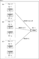
そこで、本開示においては、図3で示されるように、送信装置131を複数のグループに分けて、グループ毎に識別子を設定し、グループ単位の識別子を用いて、送信時間、および送信周波数を設定することで、受信側の処理負荷や処理時間を低減させる。
ここで、同一グループ内において、同時に、複数の送信装置131からの送信処理が発生し、衝突を起す恐れがあるため、グループ単位の識別子は、1つのグループに対して複数に設定されるようにしてもよい。ただし、同一グループ内の複数の送信装置131において、同時に送信処理が発生し、衝突を起す確率は非常に低いので、グループを構成する送信装置131の数に対して十分に少ない数の複数の識別子が設定されればよい。また、グループを構成する送信装置131の数がそれほど多くない場合については、衝突の可能性は低いので、グループ単位の識別子は1個であってもよい。
また、送信データのヘッダは、通常は、個別の送信装置131の識別子が格納されるため、どの送信装置131が送信したものであるのかを識別することができる。
しかしながら、グループ毎の識別子を用いた場合、送信装置131の個別の識別子に代えて、グループ毎の識別子が格納されることになるので、送信データを送信してきた送信装置131が属するグループは特定できるが、どの送信装置131であるのかを特定することができなくなる。
そこで、本開示においては、グループ毎の識別子をヘッダに格納する場合には、ペイロードの一部に送信装置131の識別子を格納させることにより、送信データの送信元となる送信装置131を特定できるようにする。
すなわち、図3においては、例えば、送信装置131の識別子がID=1乃至ID=aまでの送信装置131-1乃至131-aをグループGAに設定し、グループ毎の識別子を特別ID=A,B,C,Dに設定する。
また、送信装置131の識別子がID=b乃至ID=gまでの送信装置131-b乃至131-gをグループGBに設定し、グループ毎の識別子を特別ID=E,Fに設定する。
さらに、送信装置131の識別子がID=h乃至ID=nまでの送信装置131-h乃至131-nをグループGCに設定し、グループ毎の識別子を特別ID=Cに設定する。
送信装置131を個別の識別子で管理した場合、ID=1乃至nのn種類の送信時刻と送信周波数のパターンを切り換えて受信処理を管理する必要があった。
しかしながら、図3の中継器141においては、特別ID=A,B,Cの3種類の送信時間、および送信周波数のパターンを設定し、切り換えて受信処理を行うのみでよくなるため、受信処理に係る処理負荷や処理時間を低減させることが可能となる。
例えば、数千台程度の送信装置131が存在するような場合、例えば、8グループ程度に分割すると、中継器141における受信処理に係る処理負荷や処理時間は数百分の1程度となる。
結果として、中継器141は、低電力化を実現することが可能となり、例えば、太陽光発電システムやバッテリなどの小容量の電力利用することで、商用電力の供給が受けられない環境においても中継器としての機能を実現することが可能となる。
また、グループ毎の識別子を用いる場合には、送信データのペイロードに個別の識別子を格納することで、送信元となる送信装置131を特定することが可能とされている。
<<3.送信装置のハードウェア構成例>>
次に、図4を参照して、送信装置131のハードウェア構成例について説明する。
次に、図4を参照して、送信装置131のハードウェア構成例について説明する。
送信装置131は、制御部151、GPS152、操作部153、通信部154、記憶部155、ドライブ156、リムーバブル記憶部157、およびバス158より構成されている。
制御部151、GPS152、操作部153、通信部154、記憶部155、ドライブ156、およびリムーバブル記憶部157は、バス158を介して接続されており、相互にデータやプログラムに授受が可能な構成とされている。
制御部151は、プロセッサやメモリより構成されており、送信装置131の動作の全体を制御する。
また、制御部151は、緊急事態の発生を報知させる必要があるとき操作される操作部153が操作された場合、通信部GPS152により取得される位置情報に基づいて、送信データを生成する。そして、制御部151は、図3を参照して説明したようにグループを識別する識別子である特別IDに基づいて送信時刻と送信周波数を決定し、通信部154を制御して、送信データを送信する。
尚、本開示の送信装置131は、緊急事態の発生を報知させること目的とした、いわゆる警報ブザーとして機能させることを目的としたものであるが、緊急時以外の目的で送信データを送信することもできる。
以降においては、緊急事態の発生を目的とした送信を特別送信と称し、それ以外の送信を通常送信と称する。
GPS(Global Positioning System)152は、図示せぬ衛星からの信号を受信して、位置情報と共に時刻情報を取得して制御部151に出力する。
操作部153は、例えば、緊急時に引き出される紐やボタンなどにより構成され、操作に応じた信号を制御部151に出力する。すなわち、制御部151は、操作部153が操作されるとき、緊急事態が発生したことを認識し、このとき特別送信を行い、それ以外のときの送信は通常送信を行う。
通信部154は、制御部151により制御され、LPWA通信により、位置情報からなるセンサデータを含めた送信データを生成して、受信装置132または中継器141に送信する。
記憶部155は、HDD(Hard Disk Drive)、SSD(Solid State Drive)、または、半導体メモリなどからなり、制御部151により制御され、各種のデータおよびプログラムを書き込む、または、読み出す。ここでは、送信装置131を識別する固有の識別子(LPWA_ID)を記憶している。
ドライブ156は、例えば、半導体メモリなどのリムーバブル記憶部157に対してデータを読み書きする。送信装置131の識別子は、リムーバブル記憶部157に記憶されるようにしてもよい。
<<4.中継器のハードウェア構成例>>
次に、図5を参照して、中継器141のハードウェア構成例について説明する。
次に、図5を参照して、中継器141のハードウェア構成例について説明する。
中継器141は、制御部171、GPS172、操作部173、通信部174、記憶部175、ドライブ176、リムーバブル記憶部177、およびバス178より構成されている。制御部171、GPS172、操作部173、通信部174、記憶部175、ドライブ176、およびリムーバブル記憶部177は、バス178を介して接続されており、相互にデータやプログラムに授受が可能な構成とされている。
制御部171は、プロセッサやメモリより構成されており、中継器141の動作の全体を制御する。
また、制御部171は、予め送信データを送信してくる送信装置131の識別子(LPWA_ID)、および、送信装置131のグループの識別子(特別ID)を、受信装置132、またはサーバ133より取得している。
制御部171は、予め、LPWA_IDおよび特別IDのそれぞれについて、どの送信装置131、または、どの送信装置131のグループがどの時刻において、どの送信周波数で送信データを送信してくるのかについて、送信装置131における演算方式と同一の演算により求め、リスト化して記憶する。
制御部171は、記憶されたリストに基づいて、送信装置131、または、送信装置131のグループに対応付けられた受信時刻を特定すると共に、対応する送信周波数の情報を読み出す。
そして、制御部171は、受信時刻になると、通信部174を制御して、対応する送信周波数により送信されてくる送信データを受信させる。
さらに、制御部171は、通信部174を制御して、送信装置131より送信されてきた送信データを、一般的なLPWA通信によりサーバ133に送信させる。この場合、受信装置132は、LPWA通信における送信装置として機能する。
GPS(Global Positioning System)172は、図示せぬ衛星からの信号を受信して、位置情報と共に時刻情報を取得して制御部171に出力する。
操作部173は、例えば、キーボードや操作ボタンなどにより構成され、操作に応じた信号を制御部171に出力する。
通信部174は、制御部171により制御され、LPWA通信により、送信装置131より送信されてくる送信データを受信すると共に受信装置132に送信する。
記憶部175は、HDD(Hard Disk Drive)、SSD(Solid State Drive)、または、半導体メモリなどからなり、制御部151により制御され、各種のデータおよびプログラムを書き込む、または、読み出す。記憶部175は、送信データを送信してくる送信装置131を個別に識別する識別子(LPWA_ID)や送信装置131の属するグループを識別する識別子(特別ID)を記憶しており、また、識別子に基づいて、送信装置131において演算される方式と同一の方式で演算により算出された受信時刻、および送信周波数の情報が記憶されている。
ドライブ176は、例えば、半導体メモリなどのリムーバブル記憶部177に対してデータを読み書きする。
<<5.送信装置により実現される機能の構成例>>
次に、図6の機能ブロック図を参照して、送信装置131により実現される機能について説明する。現実には、送信装置131により実現される機能は、送信装置131における制御部151により実現される。
次に、図6の機能ブロック図を参照して、送信装置131により実現される機能について説明する。現実には、送信装置131により実現される機能は、送信装置131における制御部151により実現される。
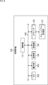
送信装置131は、通常送信パラメータ記憶部201、特別送信パラメータ記憶部202、送信パラメータ選択部203、送信時刻決定部204、選択部205、LPWA_ID記憶部206、特別ID決定部207、ID選択部208、および送信制御部209を備えている。
通常送信パラメータ記憶部201は、送信装置131が、通常送信における送信データを送信する際に使用される送信パラメータである通常送信パラメータを記憶している。
特別送信パラメータ記憶部202は、送信装置131が、緊急時となるタイミング、すなわち、ユーザにより操作部153が操作される際に使用される送信パラメータである特別送信パラメータを記憶している。
LPWA通信は、同一の送信データが規定間隔(スロット期間)内の所定のタイミング(フレーム遅延時間)でチャンネルを切り換えながら複数回連続して送受信される処理が、所定の間隔(バーストインターバル)で繰り返される。
送信パラメータとは、このLPWA通信における、規定期間(スロット期間)、規定期間内における所定のタイミング(フレーム遅延時間)、および、切り替えるチャンネルを規定するものである。
選択部205は、操作部153の操作の有無に応じて、緊急事態になったことを示す選択信号を送信パラメータ選択部203、およびID選択部208に出力する。
送信パラメータ選択部203は、選択部205より供給される選択信号が供給されない場合、すなわち、通常送信の場合、通常送信パラメータ記憶部201に記憶されている通常送信パラメータを読み出して送信時刻決定部204に出力する。
また、送信パラメータ選択部203は、選択部205より供給される選択信号が供給された場合、すなわち、緊急事態であり特別送信の場合、特別送信パラメータ記憶部202に記憶されている特別送信パラメータを選択して送信時刻決定部204に供給する。
送信時刻決定部204は、送信パラメータ選択部203により選択された通常送信パラメータ、または、特別送信パラメータと、GPS152により取得される現在時刻の情報とに基づいて送信時刻を決定し、特別ID決定部207、および送信制御部209に出力する。この際、送信時刻決定部204は、LPWA通信において送信時刻を決定する際に用いられる演算により送信時刻を決定する。
LPWA_ID記憶部206は、送信装置131に固有の識別子であるLPWA_IDを記憶しており、特別ID決定部207、ID選択部208、および送信制御部209に供給する。尚、LPWA_ID記憶部206は、記憶部155に対応する構成である。
特別ID決定部207は、送信時刻決定部204より供給される送信時刻と、LPWA_ID記憶部206に記憶されているLPWA_IDとから、送信装置131を所定のグループ数に設定したときの、送信装置131が属するグループの識別子である特別IDを算出し、ID選択部208に出力する。尚、特別ID決定部207の詳細な構成については、図8を参照して詳細を後述する。
ID選択部208は、選択部205より供給される緊急事態になったことを示す選択信号が供給されない場合、LPWA_ID記憶部206に記憶されているLPWA_IDを選択してModulationIDとして送信制御部209に出力する。
また、ID選択部208は、選択部205より供給される緊急事態になったことを示す選択信号が供給された場合、特別ID決定部207により決定された特別IDを選択してModulationIDとして送信制御部209に出力する。
送信制御部209は、送信時刻の情報、およびModulationIDに基づいて、通信部154を制御してGPS152により取得された位置情報をペイロードに格納して中継器141または受信装置132に送信する。
この際、ModulationIDが特別IDである場合には、送信制御部209は、図7の上段で示されるようなフォーマットからなる送信データを生成して、通信部154より送信させる。
すなわち、送信制御部209は、32bitのヘッダ部に特別IDからなるModulationIDを格納し、さらに、128bitのペイロードのうち、40bitに特別IDを格納すると共に、残りの88bitを用いてGPS152により取得された位置情報を格納し、更に、24bitのCRC部を付与して、送信データを生成する。
また、ModulationIDがLPWA_IDである場合には、送信制御部209は、図7の下段で示されるようなフォーマットからなる送信データを生成して、通信部154より送信させる。
すなわち、送信制御部209は、32bitのヘッダ部にLPWA_IDを格納し、さらに、128bitのペイロードにGPS152により取得された位置情報を格納し、更に、24bitのCRC部を付与して、送信データを生成する。
<特別ID決定部の構成例>
ここで、図8を参照して、特別ID決定部207の構成例について説明する。
ここで、図8を参照して、特別ID決定部207の構成例について説明する。
特別ID決定部207は、LFSR221,222、およびPRN223を備えている。
LFSR(Linear Feedback Shift Register)221,222は、それぞれLPWA_ID、および送信時刻を初期値として、特別IDとして設定する所定の個数に応じた、ビット数のLFSR多項式を演算し、演算結果をPRN(擬似乱数生成部)223に出力する。
擬似乱数生成部223は、LFSR221,222の演算結果に基づいて、擬似乱数(PRN)を生成することで、所定の個数の特別IDのインデックスとなる値を生成する。
すなわち、特別ID決定部207は、LPWA_ID、時刻情報、および自らが属するグループに設定される特別IDの個数の情報に基づいて、所定個数の特別IDのいずれかを特定するインデックスを出力する。従って、ID選択部208は、特別IDを選択する場合、特別ID決定部207より供給されるインデックスに基づいて、予めインデックスと対応付けて設定されている特別IDを選択する。
ここで、時刻情報は、例えば、複数の送信装置131により特別送信がなされるとき、異なる特別IDが設定されるようにするためのパラメータであればよく、例えば、前回の送信完了時刻や、操作部153が操作された時刻でよい。また、1つのグループに設定される特別IDの個数は、例えば、ビット単位で指定され、3ビットの場合、8(=23)個のように指定される。
この場合、LPWA_IDと時刻情報との情報に基づいて、送信装置131は、1グループに8個の特別IDを割り付ける。
従って、1グループに属する送信装置131のうち、8個以上の送信装置131が同時に特別送信する場合、特別IDの衝突が発生することになる。このため、1グループに設定される特別IDの個数は、1グループに設定される送信装置131のうち、同時に特別送信する送信装置131が発生し得る確立等に応じて設定される必要があり、同時に必要とされる可能性のある最大値がカバーされる個数に設定されればよい。
以上のような構成により、送信装置131は、緊急事態が発生するような場合において、特別IDをヘッダに付与し、ペイロードにLPWA_IDと位置情報を格納したフォーマットの送信データを生成して中継器141に送信する。
<<6.中継器により実現される機能の構成例>>
次に、図9の機能ブロック図を参照して、中継器141により実現される機能について説明する。現実には、中継器141により実現される機能は、中継器141における制御部171により実現される。
次に、図9の機能ブロック図を参照して、中継器141により実現される機能について説明する。現実には、中継器141により実現される機能は、中継器141における制御部171により実現される。
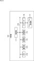
中継器141は、受信時刻リスト記憶部241、時刻情報取得部242、受信制御部243、特別ID処理部244、および送信制御部245を備えている。
受信時刻リスト記憶部241は、送信データが送信されてくる可能性のある全ての送信装置131の特別IDやLPWA_ID毎に割り付けられた送信装置131からの送信データを受信する受信時刻リストの情報を記憶している。
尚、受信時刻については、送信装置131と中継器141や受信装置132により共有されている送信パラメータ、および送信装置131の特別IDやLPWA_IDに基づいて、求めることが可能である。
そこで、中継器141は、送信データが送信されてくる可能性のある送信装置131の特別IDやLPWA_IDを取得したタイミングで、受信時刻を算出し、受信時刻リスト記憶部241に記憶させるようにしてもよい。
送信データが送信されてくる可能性のある送信装置131の特別IDやLPWA_IDは、製造時に記憶部175に記憶させるようにしてもよいし、所定のタイミングで受信装置132を介してサーバ133から供給されるようにしてもよい。
さらに、送信装置131が、共有されている送信パラメータにより特定の決まったタイミングで、LPWA_IDを送信する。そして、中継器141が、送信データが送信されてくる可能性のある送信装置131の識別子として、このLPWA_IDを取得して、受信時刻や送信周波数を演算により求めて受信時刻リスト記憶部241に登録するようにしてもよい。
また、中継器141は、送信装置131の特別IDやLPWA_IDに基づいて、受信時刻に応じて送信周波数を変更させる処理を繰り返すため、対象となる送信装置131の数が多くなると、すなわち、特別IDやLPWA_IDの数が多くなると受信時刻に応じた送信周波数の変更を頻繁に繰り返す必要が生じるため処理負荷が増大する。
そこで、太陽電池やバッテリなど、小容量の電力により稼働する中継器141については、通信対象を特別IDのみとすることで、受信時刻に応じた送信周波数の変更の頻度を低減させることで処理負荷を低減させることが可能となり、中継器141の装置の小型化、軽量化、および低消費電力化を実現させることができる。
時刻情報取得部242は、GPS172から供給される現在の時刻情報を取得して受信制御部243および送信制御部245に供給する。
受信制御部243は、受信時刻リスト記憶部241に記憶されている受信時刻の情報と、時刻情報取得部242より供給されてくる現在の時刻情報とに基づいて、いずれかの送信装置131から送信されてくる送信データの受信時刻であるか否かを判定する。
そして、受信制御部243は、受信時刻になると、特別IDやLPWA_IDに対応するModulationIDに応じて通信部174を制御して、送信データを受信させ、特別ID処理部244に供給させる。
特別ID処理部244は、受信された送信データのヘッダに含まれるModulationIDが通常のLPWA_IDであるのか、特別IDであるのかを判定し、特別IDである場合、すなわち、特別送信である場合、ペイロードに格納されているLPWA_IDおよび位置情報を抽出する。そして、特別ID処理部244は、抽出したLPWA_IDをヘッダに格納し、位置情報をペイロードに格納したフォーマットの、中継器141の送信データを生成して送信制御部245に出力する。
また、特別ID処理部244は、送信データのヘッダに含まれるModulationIDが通常のLPWA_IDである場合、つまり、通常送信である場合、受信した送信データをそのまま、中継器141の送信データとして送信制御部245に出力する。
送信制御部245は、通信部174を制御して、通常のLPWA通信により、中継器141の送信データとして、送信装置131より送信されてきた送信データを中継して受信装置132に送信する。
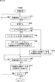
<<7.送信装置による送信処理>>
次に、図10のフローチャートを参照して、送信装置131による送信処理について説明する。
次に、図10のフローチャートを参照して、送信装置131による送信処理について説明する。
ステップS11において、選択部205は、操作部153の操作状態を認識し、何らかのトリガが入ったか否かを判定し、トリガが入るまで同様の処理を繰り返す。
ここでいうトリガとは、例えば、緊急事態が発生したことを示す操作や、緊急事態ではなく、通常の操作として、ユーザが自発的に位置情報を送信するような操作をしたか否かを示すものである。
従って、何らかの操作がなされるまで、ステップS11の処理が繰り返される。
ステップS11において、トリガが入ったとみなされた場合、処理は、ステップS12に進む。
ステップS12において、選択部205は、緊急事態が発生したことを示すトリガであり、特別送信であるか否かを判定する。ステップS12において、特別送信である場合、処理は、ステップS13に進む。
ステップS13において、選択部205は、送信パラメータ選択部203、およびID選択部208に対して特別送信であることを示す情報を通知する。これに応じて、送信パラメータ選択部203は、特別送信パラメータ記憶部202に記憶されている特別送信パラメータを読み出し送信時刻決定部204に出力する。
ステップS14において、送信時刻決定部204は、GPS152により取得される現在時刻の情報と、特別送信パラメータとに基づいて、LPWA通信における演算方式で送信時刻を算出し、特別ID決定部207および送信制御部209に出力する。
ステップS15において、特別ID決定部207は、前回の送信完了時刻、または、操作部153が操作された時刻情報等の時刻情報、LPWA_ID記憶部206のLPWA_ID、および特別IDの個数に基づいて、特別IDを決定し、ID選択部208に出力する。
ステップS16において、ID選択部208は、特別ID決定部207により決定された特別IDを取得し、ModulationIDとして送信制御部209に出力する。
ステップS17において、送信制御部209は、特別IDからなるModulationIDをヘッダとし、LPWA_ID記憶部206に記憶されているLPWA_IDをペイロードに格納して送信データを生成する。
ステップS18において、送信制御部209は、GPS152より位置情報を取得して、LPWA_IDと共にペイロードに格納して送信データを完成させる。
ステップS19において、送信制御部209は、GPS152より時刻情報を取得して送信時刻になったか否かを判定し、送信時刻になるまで同様の処理を繰り返す。そして、ステップS19において、送信時刻になった場合、処理は、ステップS20に進む。
ステップS20において、送信制御部209は、通信部154を制御して、ModulationIDに対応する送信周波数で、送信データを中継器141、または、受信装置132に送信する。
ステップS21において、送信処理の終了が指示されたか否かが判定され、終了が指示されていないと判定された場合、処理は、ステップS11に戻り、それ以降の処理が繰り返される。また、ステップS21において、終了が指示されたと判定された場合、処理は終了する。
また、ステップS12において、特別送信ではなく、通常送信であるとみなされた場合、処理は、ステップS22に進む。
ステップS22において、送信パラメータ選択部203は、通常送信パラメータ記憶部201に記憶されている通常送信パラメータを読み出して、送信時刻決定部204に出力する。
ステップS23において、送信時刻決定部204は、GPS152により取得される現在時刻の情報と、通常送信パラメータとに基づいて、LPWA通信における演算方式で送信時刻を算出し、通常送信パラメータと共に送信制御部209に出力する。
ステップS24において、送信制御部209は、LPWA_ID記憶部206に記憶されているLPWA_IDを取得する。
ステップS25において、送信制御部209は、LPWA_IDをヘッダにしたフォーマットの送信データを生成する。
そして、以降のステップS18乃至S20の処理により、LPWA_IDをヘッダにし、ペイロードに位置情報が格納されたフォーマットの送信データが、LPWA_IDからなるModulationIDに対応する送信周波数で送信される。
以上の処理により、緊急事態の発生を通知するような特別送信においては、特別IDがModulationIDに設定されてヘッダに格納され、さらにペイロードに送信装置131固有のLPWA_IDとセンシングデータである位置情報が格納された送信データを送信することが可能となる。
<<8.中継器による中継処理>>
次に、図11のフローチャートを参照して、中継器141による中継処理について説明する。
次に、図11のフローチャートを参照して、中継器141による中継処理について説明する。
ステップS41において、受信制御部243は、時刻情報取得部242より供給される現在時刻の情報に基づいて、受信時刻リスト記憶部241に記憶されている受信時刻の情報を検索し、受信時刻になったか否かを判定し、受信時刻になるまで、同様の処理が繰り返される。
ステップS41において、受信時刻になったとみなされた場合、処理は、ステップS42に進む。
ステップS42において、受信制御部243は、受信時刻リスト記憶部241において、受信時刻と対応付けて記録されている特別ID、またはLPWA_IDからなるModulationIDに基づいて、通信部174の受信周波数を制御して、送信されてくる送信データを受信させ、特別ID処理部244に出力させる。
ステップS43において、特別ID処理部244は、受信した送信データにおけるヘッダに格納されているModulationIDに基づいて、特別IDであるか否か、すなわち、特別送信であるか否かを判定する。特別IDである場合、すなわち、特別送信である場合、処理は、ステップS44に進む。
ステップS44において、特別ID処理部244は、受信した送信データのペイロードよりLPWA_IDを読み出す。
ステップS45において、特別ID処理部244は、読み出したLPDA_IDをヘッダとし、ペイロードに送信されてきた位置情報を格納した、通常のLPDA通信におけるフォーマットの中継器141の送信データを生成し、送信制御部245に出力する。
ステップS46において、送信制御部245は、時刻情報取得部242より供給される現在の時刻情報に基づいて、受信装置132への通常のLPWA通信における送信時刻となったか否かを判定し、送信時刻になるまで、同様の処理が繰り返される。
そして、ステップS46において、送信時刻になったと判定された場合、処理は、ステップS47に進む。
ステップS47において、送信制御部245は、送信データのヘッダとなるLPWA_IDからなるModulationIDに基づいて、通信部174を制御して、通常のLPWA通信により受信装置132に送信データを送信する。
ステップS48において、中継処理の終了が指示されたか否かが判定されて、終了が指示されていないと判定された場合、処理は、ステップS41に戻り、それ以降の処理が繰り返される。また、ステップS48において、終了が指示された場合、処理は終了する。
また、ステップS43において、ヘッダが特別IDではない場合、すなわち、LPWA_IDからなるヘッダであり、通常送信である場合、処理は、ステップS49に進む。
ステップS49において、特別ID処理部244は、受信した送信装置131から送信されてきた送信データを、そのまま中継器141の送信データとし、処理は、ステップS46に進む。そして、ステップS46乃至S48の処理により、送信データは、通常のLPWA通信により受信装置132に送信される。この一連の処理により、送信装置131から送信されてきた送信データが、中継器141により中継されて、受信装置132に送信される。
尚、以上においては、中継器141における中継処理について説明してきたが、受信装置132においても同様の処理により送信データを受信することができる。
受信装置132においては、ヘッダに格納されているModulationIDが特別IDであるとき、すなわち、特別送信であるときには、ペイロードに格納されたLPWA_IDが読み出されて、通常送信で受信される送信データと同様に位置情報と対応付けてサーバ133に出力される。
以上の処理により、大量の送信装置131を対象とする中継器141であっても、僅かな数の特別IDのみを通信対象とすることで、通信としては、複数の送信装置131からなるグループ用として割り当てられた僅かな種類の送信周波数の切り替え処理をするだけでよくなる。
これにより、中継器141における受信処理に係る処理負荷を低減させることができるので、受信設備の小型化、軽量化、および低消費電力化を実現することが可能となる。
また、特別IDは、送信時刻に基づいて、ランダムに選択されることになるので、衝突の発生を抑制し、アプリケーションに応じた最大同時通信数を選択することが可能となる。
さらに、LPWA通信においては、送信装置131における送信時間の範囲を指定することができるので、複数のグループIDである特別IDが近接する送信時間範囲となるように指定できる。
このため、ほぼ同時に複数の送信装置131から特別送信が発生するような状況になったも、中継器141側での中継処理の時間が大きく伸びることがなくなる。
いずれにおいても、結果として、商用電源が確保できないような場所であっても、太陽電池やバッテリ等の小容量の電力による中継器を実現させることが可能となる。
<<9.ソフトウェアにより実行させる例>>
ところで、上述した一連の処理は、ハードウェアにより実行させることもできるが、ソフトウェアにより実行させることもできる。一連の処理をソフトウェアにより実行させる場合には、そのソフトウェアを構成するプログラムが、専用のハードウェアに組み込まれているコンピュータ、または、各種のプログラムをインストールすることで、各種の機能を実行することが可能な、例えば汎用のコンピュータなどに、記録媒体からインストールされる。
ところで、上述した一連の処理は、ハードウェアにより実行させることもできるが、ソフトウェアにより実行させることもできる。一連の処理をソフトウェアにより実行させる場合には、そのソフトウェアを構成するプログラムが、専用のハードウェアに組み込まれているコンピュータ、または、各種のプログラムをインストールすることで、各種の機能を実行することが可能な、例えば汎用のコンピュータなどに、記録媒体からインストールされる。
図12は、汎用のコンピュータの構成例を示している。このパーソナルコンピュータは、CPU(Central Processing Unit)1001を内蔵している。CPU1001にはバス1004を介して、入出力インタフェース1005が接続されている。バス1004には、ROM(Read Only Memory)1002およびRAM(Random Access Memory)1003が接続されている。
入出力インタフェース1005には、ユーザが操作コマンドを入力するキーボード、マウスなどの入力デバイスよりなる入力部1006、処理操作画面や処理結果の画像を表示デバイスに出力する出力部1007、プログラムや各種データを格納するハードディスクドライブなどよりなる記憶部1008、LAN(Local Area Network)アダプタなどよりなり、インターネットに代表されるネットワークを介した通信処理を実行する通信部1009が接続されている。また、磁気ディスク(フレキシブルディスクを含む)、光ディスク(CD-ROM(Compact Disc-Read Only Memory)、DVD(Digital Versatile Disc)を含む)、光磁気ディスク(MD(Mini Disc)を含む)、もしくは半導体メモリなどのリムーバブル記憶媒体1011に対してデータを読み書きするドライブ1010が接続されている。
CPU1001は、ROM1002に記憶されているプログラム、または磁気ディスク、光ディスク、光磁気ディスク、もしくは半導体メモリ等のリムーバブル記憶媒体1011ら読み出されて記憶部1008にインストールされ、記憶部1008からRAM1003にロードされたプログラムに従って各種の処理を実行する。RAM1003にはまた、CPU1001が各種の処理を実行する上において必要なデータなども適宜記憶される。
以上のように構成されるコンピュータでは、CPU1001が、例えば、記憶部1008に記憶されているプログラムを、入出力インタフェース1005及びバス1004を介して、RAM1003にロードして実行することにより、上述した一連の処理が行われる。
コンピュータ(CPU1001)が実行するプログラムは、例えば、パッケージメディア等としてのリムーバブル記憶媒体1011に記録して提供することができる。また、プログラムは、ローカルエリアネットワーク、インターネット、デジタル衛星放送といった、有線または無線の伝送媒体を介して提供することができる。
コンピュータでは、プログラムは、リムーバブル記憶媒体1011をドライブ1010に装着することにより、入出力インタフェース1005を介して、記憶部1008にインストールすることができる。また、プログラムは、有線または無線の伝送媒体を介して、通信部1009で受信し、記憶部1008にインストールすることができる。その他、プログラムは、ROM1002や記憶部1008に、あらかじめインストールしておくことができる。
なお、コンピュータが実行するプログラムは、本明細書で説明する順序に沿って時系列に処理が行われるプログラムであっても良いし、並列に、あるいは呼び出しが行われたとき等の必要なタイミングで処理が行われるプログラムであっても良い。
尚、図12におけるCPU1001が、図4の制御部151および図5の制御部171の機能を実現させる。
また、本明細書において、システムとは、複数の構成要素(装置、モジュール(部品)等)の集合を意味し、すべての構成要素が同一筐体中にあるか否かは問わない。したがって、別個の筐体に収納され、ネットワークを介して接続されている複数の装置、及び、1つの筐体の中に複数のモジュールが収納されている1つの装置は、いずれも、システムである。
なお、本開示の実施の形態は、上述した実施の形態に限定されるものではなく、本開示の要旨を逸脱しない範囲において種々の変更が可能である。
例えば、本開示は、1つの機能をネットワークを介して複数の装置で分担、共同して処理するクラウドコンピューティングの構成をとることができる。
また、上述のフローチャートで説明した各ステップは、1つの装置で実行する他、複数の装置で分担して実行することができる。
さらに、1つのステップに複数の処理が含まれる場合には、その1つのステップに含まれる複数の処理は、1つの装置で実行する他、複数の装置で分担して実行することができる。
尚、本開示は、以下のような構成も取ることができる。
<1> 自らの個体識別情報と、前記自らと受信装置とで共有している通信間隔情報とに基づいた、通信時刻、および通信周波数で通信データの前記受信装置への送信を制御する送信制御部を備え、
前記送信制御部は、特定の通信において、前記自らを含めた複数の送信装置を複数のグループに分割したとき、前記自らが属するグループに設定されるグループ識別情報と、前記自らと前記受信装置とで共有している通信間隔情報とに基づいた、前記通信時刻、および前記通信周波数で通信データの前記受信装置への送信を制御する
送信装置。
<2> 前記送信制御部は、前記特定の通信において、ペイロードに前記自らの個体識別情報を格納させた前記通信データを生成し、前記受信装置への送信を制御する
<1>に記載の送信装置。
<3>前記個体識別情報、時刻情報、および自らのグループに設定される前記グループ識別情報の個数に基づいて、前記グループ識別情報を決定するグループ識別情報決定部をさらに含む
<1>または<2>に記載の送信装置。
<4> グループ識別情報決定部は、前記個体識別情報、および前記時刻情報を初期値としてLFSR(Linear Feedback Shift Register)を用いたときの、前記グループ識別情報の個数に対応するビット数の擬似乱数を用いて、前記グループ識別情報を決定する
<3>に記載の送信装置。
<5> 緊急事態が発生したときに操作される操作部をさらに含み、
前記時刻情報は、前回の前記特定の通信が完了した時刻、または、前記操作部が操作された時刻を含む
<3>に記載の送信装置。
<6> 前記操作部が操作されたとき、前記送信制御部は、前記特定の通信により、前記通信データを前記受信装置に送信する
<5>に記載の送信装置。
<7> 前記通信間隔情報と現在時刻情報に基づいて前記通信時刻を決定する通信時刻決定部をさらに含む
<1>乃至<6>のいずれかに記載の送信装置。
<8> 現在時刻情報は、GPS(Global Positioning System)装置により取得される時刻情報である
<7>に記載の送信装置。
<9> 前記通信データのペイロードには、前記GPS(Global Positioning System)装置により取得される位置情報が格納される
<8>に記載の送信装置。
<10> 自らの個体識別情報と、前記自らと受信装置とで共有している通信間隔情報とに基づいた、通信時刻、および通信周波数で通信データの前記受信装置への送信を制御する送信制御部を備えた送信装置の送信方法であって、
前記送信制御部が、特定の通信において、前記自らを含めた複数の送信装置を複数のグループに分割したとき、前記自らが属するグループに設定されるグループ識別情報と、前記自らと前記受信装置とで共有している通信間隔情報とに基づいた、前記通信時刻、および前記通信周波数で通信データの前記受信装置への送信を制御する
送信方法。
<11> 複数の送信装置の個体識別情報と、前記送信装置と自らとで共有している通信間隔情報とに基づいた、通信時刻、および通信周波数で通信データの受信を制御する受信制御部を備え、
前記受信制御部は、特定の通信において、前記複数の前記送信装置を複数のグループに分割したとき、前記送信装置が属するグループに設定されるグループ識別情報と、前記送信装置と自らとで共有している通信間隔情報とに基づいた、前記通信時刻、および前記通信周波数で通信データの受信を制御する
受信装置。
<12> 前記受信制御部は、受信した前記通信データのペイロードに前記グループ識別情報が格納されているとき、前記特定の通信として、前記通信データの受信を制御する
<11>に記載の受信装置。
<13> 前記グループ識別情報は、前記通信データを送信してきた前記送信装置の個体識別情報、時刻情報、および自らのグループに設定される前記グループ識別情報の個数に基づいて決定される
<11>または<12>に記載の受信装置。
<14> 前記グループ識別情報は、前記個体識別情報、および前記時刻情報を初期値としてLFSR(Linear Feedback Shift Register)を用いたときの、前記グループ識別情報の個数に対応するビット数の擬似乱数を用いて決定される
<13>に記載の受信装置。
<15> 前記通信時刻は、前記通信間隔情報と現在時刻情報に基づいて決定される
<11>乃至<14>のいずれかに記載の受信装置。
<16> 前記現在時刻情報は、GPS(Global Positioning System)装置により取得される時刻情報である
<15>に記載の受信装置。
<17> 前記通信データのペイロードには、前記送信装置のGPS(Global Positioning System)装置により取得される位置情報が格納される
<16>に記載の受信装置。
<18> 前記特定の通信は、前記送信装置において、緊急事態が発生したときに操作される操作部が操作されたときに、前記送信装置の位置情報がペイロードに格納された前記通信データが送信される通信である
<11>乃至<17>のいずれかに記載の受信装置。
<19> 前記受信制御部により受信された通信データを、中継して他の受信装置に送信する送信制御部をさらに含む
<11>乃至<18>のいずれかに記載の受信装置。
<20> 複数の送信装置の個体識別情報と、前記送信装置と自らとで共有している通信間隔情報とに基づいた、通信時刻、および通信周波数で通信データの受信を制御する受信制御部を備えた受信装置における受信方法であって、
前記受信制御部が、特定の通信において、前記複数の前記送信装置を複数のグループに分割したとき、前記送信装置が属するグループに設定されるグループ識別情報と、前記送信装置と自らとで共有している通信間隔情報とに基づいた、前記通信時刻、および前記通信周波数で通信データの受信を制御する
受信方法。
前記送信制御部は、特定の通信において、前記自らを含めた複数の送信装置を複数のグループに分割したとき、前記自らが属するグループに設定されるグループ識別情報と、前記自らと前記受信装置とで共有している通信間隔情報とに基づいた、前記通信時刻、および前記通信周波数で通信データの前記受信装置への送信を制御する
送信装置。
<2> 前記送信制御部は、前記特定の通信において、ペイロードに前記自らの個体識別情報を格納させた前記通信データを生成し、前記受信装置への送信を制御する
<1>に記載の送信装置。
<3>前記個体識別情報、時刻情報、および自らのグループに設定される前記グループ識別情報の個数に基づいて、前記グループ識別情報を決定するグループ識別情報決定部をさらに含む
<1>または<2>に記載の送信装置。
<4> グループ識別情報決定部は、前記個体識別情報、および前記時刻情報を初期値としてLFSR(Linear Feedback Shift Register)を用いたときの、前記グループ識別情報の個数に対応するビット数の擬似乱数を用いて、前記グループ識別情報を決定する
<3>に記載の送信装置。
<5> 緊急事態が発生したときに操作される操作部をさらに含み、
前記時刻情報は、前回の前記特定の通信が完了した時刻、または、前記操作部が操作された時刻を含む
<3>に記載の送信装置。
<6> 前記操作部が操作されたとき、前記送信制御部は、前記特定の通信により、前記通信データを前記受信装置に送信する
<5>に記載の送信装置。
<7> 前記通信間隔情報と現在時刻情報に基づいて前記通信時刻を決定する通信時刻決定部をさらに含む
<1>乃至<6>のいずれかに記載の送信装置。
<8> 現在時刻情報は、GPS(Global Positioning System)装置により取得される時刻情報である
<7>に記載の送信装置。
<9> 前記通信データのペイロードには、前記GPS(Global Positioning System)装置により取得される位置情報が格納される
<8>に記載の送信装置。
<10> 自らの個体識別情報と、前記自らと受信装置とで共有している通信間隔情報とに基づいた、通信時刻、および通信周波数で通信データの前記受信装置への送信を制御する送信制御部を備えた送信装置の送信方法であって、
前記送信制御部が、特定の通信において、前記自らを含めた複数の送信装置を複数のグループに分割したとき、前記自らが属するグループに設定されるグループ識別情報と、前記自らと前記受信装置とで共有している通信間隔情報とに基づいた、前記通信時刻、および前記通信周波数で通信データの前記受信装置への送信を制御する
送信方法。
<11> 複数の送信装置の個体識別情報と、前記送信装置と自らとで共有している通信間隔情報とに基づいた、通信時刻、および通信周波数で通信データの受信を制御する受信制御部を備え、
前記受信制御部は、特定の通信において、前記複数の前記送信装置を複数のグループに分割したとき、前記送信装置が属するグループに設定されるグループ識別情報と、前記送信装置と自らとで共有している通信間隔情報とに基づいた、前記通信時刻、および前記通信周波数で通信データの受信を制御する
受信装置。
<12> 前記受信制御部は、受信した前記通信データのペイロードに前記グループ識別情報が格納されているとき、前記特定の通信として、前記通信データの受信を制御する
<11>に記載の受信装置。
<13> 前記グループ識別情報は、前記通信データを送信してきた前記送信装置の個体識別情報、時刻情報、および自らのグループに設定される前記グループ識別情報の個数に基づいて決定される
<11>または<12>に記載の受信装置。
<14> 前記グループ識別情報は、前記個体識別情報、および前記時刻情報を初期値としてLFSR(Linear Feedback Shift Register)を用いたときの、前記グループ識別情報の個数に対応するビット数の擬似乱数を用いて決定される
<13>に記載の受信装置。
<15> 前記通信時刻は、前記通信間隔情報と現在時刻情報に基づいて決定される
<11>乃至<14>のいずれかに記載の受信装置。
<16> 前記現在時刻情報は、GPS(Global Positioning System)装置により取得される時刻情報である
<15>に記載の受信装置。
<17> 前記通信データのペイロードには、前記送信装置のGPS(Global Positioning System)装置により取得される位置情報が格納される
<16>に記載の受信装置。
<18> 前記特定の通信は、前記送信装置において、緊急事態が発生したときに操作される操作部が操作されたときに、前記送信装置の位置情報がペイロードに格納された前記通信データが送信される通信である
<11>乃至<17>のいずれかに記載の受信装置。
<19> 前記受信制御部により受信された通信データを、中継して他の受信装置に送信する送信制御部をさらに含む
<11>乃至<18>のいずれかに記載の受信装置。
<20> 複数の送信装置の個体識別情報と、前記送信装置と自らとで共有している通信間隔情報とに基づいた、通信時刻、および通信周波数で通信データの受信を制御する受信制御部を備えた受信装置における受信方法であって、
前記受信制御部が、特定の通信において、前記複数の前記送信装置を複数のグループに分割したとき、前記送信装置が属するグループに設定されるグループ識別情報と、前記送信装置と自らとで共有している通信間隔情報とに基づいた、前記通信時刻、および前記通信周波数で通信データの受信を制御する
受信方法。
101 通信システム, 131 送信装置, 132 受信装置, 133 クラウドサーバ, 141 中継器, 151 制御部, 152 GPS, 153 操作部, 154 通信部, 155 記憶部, 156 ドライブ, 157 リムーバブル記憶部, 171 制御部, 172 GPS, 173 操作部, 174 通信部, 175 記憶部, 176 ドライブ, 177 リムーバブル記憶部, 201 通常送信パラメータ記憶部, 202 特別送信パラメータ部, 203 送信パラメータ選択部, 204 送信時刻決定部, 205 選択部, 206 LPWA_ID記憶部, 207 特別ID決定部, 208 ID選択器, 209 送信制御部, 221,222 LFSR, 223 PRN, 241 受信時刻リスト, 242 時刻情報取得部, 243 受信制御部, 244 特別ID処理部, 245 送信制御部
Claims (20)
- 自らの個体識別情報と、前記自らと受信装置とで共有している通信間隔情報とに基づいた、通信時刻、および通信周波数で通信データの前記受信装置への送信を制御する送信制御部を備え、
前記送信制御部は、特定の通信において、前記自らを含めた複数の送信装置を複数のグループに分割したとき、前記自らが属するグループに設定されるグループ識別情報と、前記自らと前記受信装置とで共有している通信間隔情報とに基づいた、前記通信時刻、および前記通信周波数で通信データの前記受信装置への送信を制御する
送信装置。 - 前記送信制御部は、前記特定の通信において、ペイロードに前記自らの個体識別情報を格納させた前記通信データを生成し、前記受信装置への送信を制御する
請求項1に記載の送信装置。 - 前記個体識別情報、時刻情報、および自らのグループに設定される前記グループ識別情報の個数に基づいて、前記グループ識別情報を決定するグループ識別情報決定部をさらに含む
請求項1に記載の送信装置。 - グループ識別情報決定部は、前記個体識別情報、および前記時刻情報を初期値としてLFSR(Linear Feedback Shift Register)を用いたときの、前記グループ識別情報の個数に対応するビット数の擬似乱数を用いて、前記グループ識別情報を決定する
請求項3に記載の送信装置。 - 緊急事態が発生したときに操作される操作部をさらに含み、
前記時刻情報は、前回の前記特定の通信が完了した時刻、または、前記操作部が操作された時刻を含む
請求項3に記載の送信装置。 - 前記操作部が操作されたとき、前記送信制御部は、前記特定の通信により、前記通信データを前記受信装置に送信する
請求項5に記載の送信装置。 - 前記通信間隔情報と現在時刻情報に基づいて前記通信時刻を決定する通信時刻決定部をさらに含む
請求項1に記載の送信装置。 - 現在時刻情報は、GPS(Global Positioning System)装置により取得される時刻情報である
請求項7に記載の送信装置。 - 前記通信データのペイロードには、前記GPS(Global Positioning System)装置により取得される位置情報が格納される
請求項8に記載の送信装置。 - 自らの個体識別情報と、前記自らと受信装置とで共有している通信間隔情報とに基づいた、通信時刻、および通信周波数で通信データの前記受信装置への送信を制御する送信制御部を備えた送信装置の送信方法であって、
前記送信制御部が、特定の通信において、前記自らを含めた複数の送信装置を複数のグループに分割したとき、前記自らが属するグループに設定されるグループ識別情報と、前記自らと前記受信装置とで共有している通信間隔情報とに基づいた、前記通信時刻、および前記通信周波数で通信データの前記受信装置への送信を制御する
送信方法。 - 複数の送信装置の個体識別情報と、前記送信装置と自らとで共有している通信間隔情報とに基づいた、通信時刻、および通信周波数で通信データの受信を制御する受信制御部を備え、
前記受信制御部は、特定の通信において、前記複数の前記送信装置を複数のグループに分割したとき、前記送信装置が属するグループに設定されるグループ識別情報と、前記送信装置と自らとで共有している通信間隔情報とに基づいた、前記通信時刻、および前記通信周波数で通信データの受信を制御する
受信装置。 - 前記受信制御部は、受信した前記通信データのペイロードに前記グループ識別情報が格納されているとき、前記特定の通信として、前記通信データの受信を制御する
請求項11に記載の受信装置。 - 前記グループ識別情報は、前記通信データを送信してきた前記送信装置の個体識別情報、時刻情報、および自らのグループに設定される前記グループ識別情報の個数に基づいて決定される
請求項11に記載の受信装置。 - 前記グループ識別情報は、前記個体識別情報、および前記時刻情報を初期値としてLFSR(Linear Feedback Shift Register)を用いたときの、前記グループ識別情報の個数に対応するビット数の擬似乱数を用いて決定される
請求項13に記載の受信装置。 - 前記通信時刻は、前記通信間隔情報と現在時刻情報に基づいて決定される
請求項11に記載の受信装置。 - 前記現在時刻情報は、GPS(Global Positioning System)装置により取得される時刻情報である
請求項15に記載の受信装置。 - 前記通信データのペイロードには、前記送信装置のGPS(Global Positioning System)装置により取得される位置情報が格納される
請求項16に記載の受信装置。 - 前記特定の通信は、前記送信装置において、緊急事態が発生したときに操作される操作部が操作されたときに、前記送信装置の位置情報がペイロードに格納された前記通信データが送信される通信である
請求項11に記載の受信装置。 - 前記受信制御部により受信された通信データを、中継して他の受信装置に送信する送信制御部をさらに含む
請求項11に記載の受信装置。 - 複数の送信装置の個体識別情報と、前記送信装置と自らとで共有している通信間隔情報とに基づいた、通信時刻、および通信周波数で通信データの受信を制御する受信制御部を備えた受信装置における受信方法であって、
前記受信制御部が、特定の通信において、前記複数の前記送信装置を複数のグループに分割したとき、前記送信装置が属するグループに設定されるグループ識別情報と、前記送信装置と自らとで共有している通信間隔情報とに基づいた、前記通信時刻、および前記通信周波数で通信データの受信を制御する
受信方法。
Priority Applications (2)
| Application Number | Priority Date | Filing Date | Title |
|---|---|---|---|
| JP2020561278A JP7443247B2 (ja) | 2018-12-17 | 2019-12-04 | 送信装置および送信方法、並びに受信装置および受信方法 |
| US17/311,774 US12108423B2 (en) | 2018-12-17 | 2019-12-04 | Transmission apparatus, transmission method, reception apparatus, and reception method |
Applications Claiming Priority (2)
| Application Number | Priority Date | Filing Date | Title |
|---|---|---|---|
| JP2018235682 | 2018-12-17 | ||
| JP2018-235682 | 2018-12-17 |
Publications (1)
| Publication Number | Publication Date |
|---|---|
| WO2020129634A1 true WO2020129634A1 (ja) | 2020-06-25 |
Family
ID=71102781
Family Applications (1)
| Application Number | Title | Priority Date | Filing Date |
|---|---|---|---|
| PCT/JP2019/047340 Ceased WO2020129634A1 (ja) | 2018-12-17 | 2019-12-04 | 送信装置および送信方法、並びに受信装置および受信方法 |
Country Status (3)
| Country | Link |
|---|---|
| US (1) | US12108423B2 (ja) |
| JP (1) | JP7443247B2 (ja) |
| WO (1) | WO2020129634A1 (ja) |
Cited By (1)
| Publication number | Priority date | Publication date | Assignee | Title |
|---|---|---|---|---|
| JP2022050874A (ja) * | 2020-09-18 | 2022-03-31 | 日本ユニシス株式会社 | 環境情報提供システム、センサ装置、ゲートウェイ装置、センサ装置の制御方法、及びセンサ装置のプログラム |
Citations (5)
| Publication number | Priority date | Publication date | Assignee | Title |
|---|---|---|---|---|
| JP2012525083A (ja) * | 2009-04-23 | 2012-10-18 | インターデイジタル パテント ホールディングス インコーポレイテッド | マルチキャリアワイヤレス通信におけるランダムアクセスのための方法および機器 |
| US20130286957A1 (en) * | 2010-09-27 | 2013-10-31 | Fujitsu Limited | Radio bearers for machine type communication |
| JP2017069593A (ja) * | 2015-09-28 | 2017-04-06 | 富士通株式会社 | 通信方法、通信プログラム、及び無線端末 |
| JP2017147484A (ja) * | 2016-02-15 | 2017-08-24 | 株式会社Jvcケンウッド | 無線端末装置、通信システム、通信方法 |
| WO2017212810A1 (ja) * | 2016-06-08 | 2017-12-14 | ソニーセミコンダクタソリューションズ株式会社 | 情報処理装置および方法、送信装置および方法、並びに、受信装置および方法 |
Family Cites Families (9)
| Publication number | Priority date | Publication date | Assignee | Title |
|---|---|---|---|---|
| US20070194906A1 (en) * | 2006-02-22 | 2007-08-23 | Federal Signal Corporation | All hazard residential warning system |
| US8468269B2 (en) * | 2011-08-01 | 2013-06-18 | Motorola Solutions, Inc. | Method and system for compressing location data of a radio for over-the-air transmission |
| US8885558B2 (en) * | 2011-09-28 | 2014-11-11 | Robert Bosch Gmbh | System and method for multiple access sensor networks |
| CN103096309B (zh) * | 2011-11-01 | 2016-08-10 | 华为技术有限公司 | 生成组密钥的方法和相关设备 |
| CN103997724B (zh) * | 2013-02-17 | 2017-12-15 | 阿尔卡特朗讯 | 一种用于聚合计费信息的方法、装置和系统 |
| US10397751B2 (en) * | 2014-11-25 | 2019-08-27 | Fynd Technologies, Inc. | Geolocation bracelet, system, and methods |
| CA2988895A1 (en) * | 2016-12-16 | 2018-06-16 | Comcast Cable Communications, Llc | Systems and methods for improved geolocation in a low power wide area network |
| US10862911B2 (en) * | 2017-06-27 | 2020-12-08 | Allot Ltd. | System, device, and method of adaptive network protection for managed internet-of-things services |
| US10944753B2 (en) * | 2017-08-17 | 2021-03-09 | Verizon Patent And Licensing Inc. | IoT devices wireless network connectivity policy management |
-
2019
- 2019-12-04 JP JP2020561278A patent/JP7443247B2/ja active Active
- 2019-12-04 WO PCT/JP2019/047340 patent/WO2020129634A1/ja not_active Ceased
- 2019-12-04 US US17/311,774 patent/US12108423B2/en active Active
Patent Citations (5)
| Publication number | Priority date | Publication date | Assignee | Title |
|---|---|---|---|---|
| JP2012525083A (ja) * | 2009-04-23 | 2012-10-18 | インターデイジタル パテント ホールディングス インコーポレイテッド | マルチキャリアワイヤレス通信におけるランダムアクセスのための方法および機器 |
| US20130286957A1 (en) * | 2010-09-27 | 2013-10-31 | Fujitsu Limited | Radio bearers for machine type communication |
| JP2017069593A (ja) * | 2015-09-28 | 2017-04-06 | 富士通株式会社 | 通信方法、通信プログラム、及び無線端末 |
| JP2017147484A (ja) * | 2016-02-15 | 2017-08-24 | 株式会社Jvcケンウッド | 無線端末装置、通信システム、通信方法 |
| WO2017212810A1 (ja) * | 2016-06-08 | 2017-12-14 | ソニーセミコンダクタソリューションズ株式会社 | 情報処理装置および方法、送信装置および方法、並びに、受信装置および方法 |
Cited By (1)
| Publication number | Priority date | Publication date | Assignee | Title |
|---|---|---|---|---|
| JP2022050874A (ja) * | 2020-09-18 | 2022-03-31 | 日本ユニシス株式会社 | 環境情報提供システム、センサ装置、ゲートウェイ装置、センサ装置の制御方法、及びセンサ装置のプログラム |
Also Published As
| Publication number | Publication date |
|---|---|
| JPWO2020129634A1 (ja) | 2021-11-11 |
| US12108423B2 (en) | 2024-10-01 |
| US20220030595A1 (en) | 2022-01-27 |
| JP7443247B2 (ja) | 2024-03-05 |
Similar Documents
| Publication | Publication Date | Title |
|---|---|---|
| US12442933B2 (en) | GNSS data in non-terrestrial network system information | |
| TWI596913B (zh) | 用以在多格網路中排程無線裝置間通訊以減低與全雙工通訊相關之干擾之裝置、系統及方法 | |
| JP2006329854A (ja) | 無線通信システム、ノード位置算出方法及びノード | |
| CN116686234A (zh) | 星历数据信令-随时间的增量 | |
| KR20210153612A (ko) | 중앙 유닛 디바이스, 사용자 장비, 무선 통신 방법, 및 저장 매체 | |
| US20260086247A1 (en) | Methods and systems for signalling ephemeris data in a non-terrestrial network | |
| KR20240038140A (ko) | 신경망을 사용하는 로컬 센서를 사용한 셀룰러 포지셔닝 | |
| WO2020129634A1 (ja) | 送信装置および送信方法、並びに受信装置および受信方法 | |
| JPWO2010131484A1 (ja) | 無線通信システム、無線基地局装置、パラメーター決定装置 | |
| EP3806508B1 (en) | Information processing device, information processing method, transmitter, transmission method, receiver, and reception method | |
| JP4451878B2 (ja) | 無線基地局のアーキテクチャーモデル | |
| EP2876970B1 (en) | Communication device | |
| US20150054656A1 (en) | Base station connectivity with a beacon having internal geographic location tracking that receives the location in a short-and-instant telemetry message | |
| KR20120037864A (ko) | 적응형 항법 신호 처리를 수행하는 위성 항법 신호 수신 장치 및 방법 | |
| US20220407613A1 (en) | Communication device and operating method thereof | |
| JP4668137B2 (ja) | 位置特定システム | |
| WO2021255794A1 (ja) | 無線通信システム、無線通信システムの制御方法、無線通信システムの制御装置、及び無線通信システム制御プログラム | |
| JP6920624B2 (ja) | 無線通信装置、無線通信システム、およびプログラム | |
| US20210075466A1 (en) | Device for operating navigation satellite on basis of code division transmission array antenna and method for operating navigation satellite | |
| JP5549070B2 (ja) | 端末および通信方法 | |
| WO2021255791A1 (ja) | 無線通信システム、無線通信システムの制御方法、無線通信システムの制御装置、及び無線通信システム制御プログラム | |
| JP2025086737A (ja) | 衛星移動通信システム、衛星移動通信装置、衛星移動通信方法および衛星移動通信プログラム | |
| US10659915B2 (en) | Anti-disaster system, information generating method and storage medium | |
| WO2019171910A1 (ja) | 制御装置および制御システム | |
| WO2024202923A1 (ja) | 情報処理装置および方法 |
Legal Events
| Date | Code | Title | Description |
|---|---|---|---|
| 121 | Ep: the epo has been informed by wipo that ep was designated in this application |
Ref document number: 19898096 Country of ref document: EP Kind code of ref document: A1 |
|
| ENP | Entry into the national phase |
Ref document number: 2020561278 Country of ref document: JP Kind code of ref document: A |
|
| NENP | Non-entry into the national phase |
Ref country code: DE |
|
| 122 | Ep: pct application non-entry in european phase |
Ref document number: 19898096 Country of ref document: EP Kind code of ref document: A1 |