WO2020129401A1 - ステアリング装置 - Google Patents
ステアリング装置 Download PDFInfo
- Publication number
- WO2020129401A1 WO2020129401A1 PCT/JP2019/041749 JP2019041749W WO2020129401A1 WO 2020129401 A1 WO2020129401 A1 WO 2020129401A1 JP 2019041749 W JP2019041749 W JP 2019041749W WO 2020129401 A1 WO2020129401 A1 WO 2020129401A1
- Authority
- WO
- WIPO (PCT)
- Prior art keywords
- magnetic
- pattern
- rack
- steering device
- pole
- Prior art date
- Legal status (The legal status is an assumption and is not a legal conclusion. Google has not performed a legal analysis and makes no representation as to the accuracy of the status listed.)
- Ceased
Links
Images










Classifications
-
- B—PERFORMING OPERATIONS; TRANSPORTING
- B62—LAND VEHICLES FOR TRAVELLING OTHERWISE THAN ON RAILS
- B62D—MOTOR VEHICLES; TRAILERS
- B62D3/00—Steering gears
- B62D3/02—Steering gears mechanical
- B62D3/12—Steering gears mechanical of rack-and-pinion type
-
- G—PHYSICS
- G01—MEASURING; TESTING
- G01B—MEASURING LENGTH, THICKNESS OR SIMILAR LINEAR DIMENSIONS; MEASURING ANGLES; MEASURING AREAS; MEASURING IRREGULARITIES OF SURFACES OR CONTOURS
- G01B7/00—Measuring arrangements characterised by the use of electric or magnetic techniques
-
- G—PHYSICS
- G01—MEASURING; TESTING
- G01B—MEASURING LENGTH, THICKNESS OR SIMILAR LINEAR DIMENSIONS; MEASURING ANGLES; MEASURING AREAS; MEASURING IRREGULARITIES OF SURFACES OR CONTOURS
- G01B7/00—Measuring arrangements characterised by the use of electric or magnetic techniques
- G01B7/30—Measuring arrangements characterised by the use of electric or magnetic techniques for measuring angles or tapers; for testing the alignment of axes
-
- G—PHYSICS
- G01—MEASURING; TESTING
- G01D—MEASURING NOT SPECIALLY ADAPTED FOR A SPECIFIC VARIABLE; ARRANGEMENTS FOR MEASURING TWO OR MORE VARIABLES NOT COVERED IN A SINGLE OTHER SUBCLASS; TARIFF METERING APPARATUS; MEASURING OR TESTING NOT OTHERWISE PROVIDED FOR
- G01D5/00—Mechanical means for transferring the output of a sensing member; Means for converting the output of a sensing member to another variable where the form or nature of the sensing member does not constrain the means for converting; Transducers not specially adapted for a specific variable
- G01D5/12—Mechanical means for transferring the output of a sensing member; Means for converting the output of a sensing member to another variable where the form or nature of the sensing member does not constrain the means for converting; Transducers not specially adapted for a specific variable using electric or magnetic means
- G01D5/244—Mechanical means for transferring the output of a sensing member; Means for converting the output of a sensing member to another variable where the form or nature of the sensing member does not constrain the means for converting; Transducers not specially adapted for a specific variable using electric or magnetic means influencing characteristics of pulses or pulse trains; generating pulses or pulse trains
- G01D5/249—Mechanical means for transferring the output of a sensing member; Means for converting the output of a sensing member to another variable where the form or nature of the sensing member does not constrain the means for converting; Transducers not specially adapted for a specific variable using electric or magnetic means influencing characteristics of pulses or pulse trains; generating pulses or pulse trains using pulse code
Definitions
- the present invention relates to a steering device, and is particularly suitable for a steering device having a magnetic sensor.
- Patent Document 1 discloses a technique for measuring a tire angle from a rotation angle of a steering wheel (handle) in a steering device.
- the rack moves in the horizontal direction via the gear, and the horizontal movement of the rack changes the tire angle. Therefore, the tire angle can be known by measuring the rotation angle of the steering wheel.
- Patent Document 2 discloses a technique of forming a magnetic mark on a rack and reading the magnetic mark with a magnetic sensor to detect that the rack is located at a neutral position.
- a technique for quickly detecting a failure of the magnetic sensor is required.
- a conventional technique for detecting a failure of the magnetic sensor there is a method of using a semiconductor chip in which a coil is arranged around the magnetic sensor. In this method, the presence or absence of a failure of the magnetic sensor is determined by controlling the magnetic field generated by changing the current passed through the built-in coil and by normally detecting the change in the magnetic field.
- a semiconductor chip having such a magnetic sensor and a built-in coil is expensive and there is a problem that the manufacturing cost increases.
- a steering device includes a housing, a rack provided inside the housing and movable in a first direction, a plurality of N-pole magnetic bodies and a plurality of N-pole magnetic bodies formed on the rack. It has a magnetic pattern having an S-pole magnetic substance and a magnetic sensor attached to the housing and for detecting a magnetic signal from the magnetic pattern.
- the performance of the steering device can be improved.
- FIG. 3 is a plan view of the steering device according to the first embodiment.
- FIG. 3 is a sectional view of the steering device according to the first embodiment.
- FIG. 3 is a sectional view of the steering device according to the first embodiment.
- FIG. 3 is a sectional view of the steering device according to the first embodiment.
- FIG. 3 is a plan view of the steering device according to the first embodiment.
- FIG. 4 is a schematic diagram showing an example in which the magnetic sensor receives a magnetic signal from a magnetic pattern in the first embodiment.
- FIG. 3 is a functional block diagram for realizing rack position measurement and magnetic sensor failure detection in the first embodiment.
- 8 is a signal waveform input/output to/from each functional block in FIG. 7.
- FIG. 6 is a plan view of a steering device according to a second embodiment.
- FIG. 6 is a cross-sectional view of a steering device according to a second embodiment.
- FIG. 6 is a cross-sectional view of a steering device according to a second embodiment.
- FIG. 9 is a plan view of a steering device according to a modified example 1 of the second embodiment.
- FIG. 9 is a cross-sectional view of a steering device according to a modified example 2 of the second embodiment.
- FIG. 7 is a plan view of a steering device according to a third embodiment.
- FIG. 13 is a schematic diagram showing an example of detecting a magnetic pattern using a magnetic sensor in the fourth embodiment.
- FIG. 7 is a plan view of a steering device according to a fourth embodiment.
- FIG. 10 is a plan view of a steering device according to a fifth embodiment.
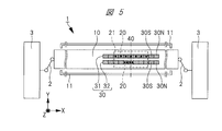
- FIG. 1 is a plan view of a steering device 1 of a vehicle such as an automobile according to the present embodiment
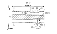
- FIG. 2 is a cross-sectional view taken along the line AA of FIG. 1
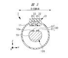
- FIG. 4 is a sectional view taken along line BB
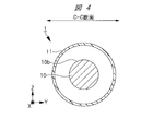
- FIG. 4 is a sectional view taken along line CC of FIG.
- FIG. 1 is a plan view, in order to make the drawing easy to see, the N-pole magnetic body 30N and the S-pole magnetic body 30S included in the magnetic pattern 30 are hatched. Similarly, in other plan views described below, the N-pole magnetic body 30N and the S-pole magnetic body 30S are hatched.
- the steering device 1 is attached to the housing 11, a rack (rod) 10 provided inside the housing 11, a magnetic pattern 30 formed on the rack 10, and the housing 11. It has a magnetic module 21, a steering wheel (handle) 12, and a shaft 13 that connects the rack 10 and the steering wheel 12.
- the shaft 13 connected to the steering wheel 12 rotates.
- the tip of the shaft 13 is provided with a gear-shaped pinion as a part of the shaft 13, and the pinion of the shaft 13 and the rack 10 are formed by the rotation of the shaft 13.
- the rack teeth 10G meshed with each other and the rack 10 moves in the X direction (longitudinal direction or moving direction of the rack 10).
- the angle of the wheel 3 changes via the tie rod 2. That is, by changing the angle of the steering wheel 12, the position of the rack 10 that can move in the X direction changes, and the angle of the wheel 3 also changes.
- the angle of the wheel 3 changes by about ⁇ 20 degrees
- the steering wheel 12 changes by about ⁇ 334 degrees. If the angle error of the steering wheel 12 is about ⁇ 0.1 degrees, the position error of the rack 10 in the X direction is about ⁇ 30 ⁇ m, and the angle error of the wheels 3 is about ⁇ 0.006 degrees. Become.
- the inventors of the present application arrange a position detecting element such as the magnetic sensor 20 in the steering device 1 to measure the position of the rack 10 with high accuracy and the angle of the wheel 3 with high accuracy. I focused on doing. In particular, the inventors of the present application focus on measuring the position of the rack 10 with high accuracy by a magnetic linear encoder provided in the steering device 1 with a magnetic pattern 30 and a magnetic module 21 having a plurality of magnetic sensors 20. did.
- a magnetic pattern 30 having a plurality of N-pole magnetic bodies 30N and a plurality of S-pole magnetic bodies 30S is formed on the rack 10 of the present embodiment.
- the magnetic pattern 30 has a thickness of 1 mm, for example.
- the magnetic pattern 30 is an absolute type capable of detecting the absolute coordinates of the rack 10, and has a coarse magnetic pattern 31 and a fine magnetic pattern 32.
- the coarse magnetic pattern 31 and the fine magnetic pattern 32 each extend in the X direction and are arranged so as to be adjacent to each other in the Y direction orthogonal to the X direction.
- the N-pole magnetic body 30N and the S-pole magnetic body 30S form an n-bit random random number code pattern (M-sequence pattern).
- the N-pole magnetic body 30N and the S-pole magnetic body 30S in the rough magnetic pattern 31 may have other patterns.
- the fine magnetic pattern 32 of the present embodiment the N-pole magnetic body 30N and the S-pole magnetic body 30S are alternately arranged.
- the coarse magnetic pattern 31 has 7 bits, and seven magnetic sensors 20 are provided on the coarse magnetic pattern 31, and four fine magnetic patterns 32 are provided on the fine magnetic pattern 32. The case where the magnetic sensor 20 is provided is illustrated. Further, the number of bits and the number of magnetic sensors 20 can be appropriately changed.
- the magnetic module 21 includes a plurality of magnetic sensors 20 mounted on the sensor substrate 22, and each magnetic sensor 20 is located between the housing 11 and the magnetic pattern 30. It is fixed to the housing 11. That is, the magnetic module 21 constitutes a part of the housing 11, and the magnetic sensor 20 included in the magnetic module 21 is attached to the housing 11 as a member used for a part of the housing 11.
- Each magnetic sensor 20 can also receive a magnetic signal from the magnetic pattern 30. Specifically, by reading a magnetic signal from the n-bit coarse adjustment magnetic pattern 31 by n magnetic sensors 20 provided on the coarse adjustment magnetic pattern 31, the absolute coordinates of the rack 10 are measured in millimeters (mm). ) Can be measured on the order. Further, by reading the magnetic periodic signal (trigonometric function wavelength) from the fine magnetic pattern 32 by the plurality of magnetic sensors 20 provided on the fine magnetic pattern 32, the relative movement of the rack 10 in the coarse magnetic pattern 31 is achieved. Coordinates can be measured on the order of micrometers ( ⁇ m).
- the magnetic pattern 30 and the plurality of magnetic sensors 20 form a magnetic linear absolute encoder in the steering device 1. Therefore, in the present embodiment, the absolute coordinates of the rack 10 in the X direction can be measured with high accuracy, and the angle of the wheel 3 can be detected with high accuracy from the result. That is, in the present embodiment, the performance of the steering device 1 can be improved.
- the rack 10 has a substantially columnar structure, but the rack 10 is processed at the portion where the rack 10 is connected to the shaft 13. , A plurality of rack teeth 10G are formed.
- the rack 10 has a flat portion 10a and a curved portion 10b in a region other than the region where the plurality of rack teeth 10G are formed.
- the magnetic pattern 30 when the magnetic pattern 30 is formed over the flat portion 10a and the curved portion 10b, the direction and magnetic force of the magnetic force lines generated from the magnetic pattern 30 vary, and the magnetic sensor 20 cannot correctly detect the magnetic signal. There is a fear.
- the magnetic pattern 30 including the coarse magnetic pattern 31 and the fine magnetic pattern 32 is formed on the flat portion 10 a of the rack 10, and the curved portion 10 b of the rack 10 is formed. Not formed on. Therefore, the above fear can be suppressed. That is, it is desirable that the entire magnetic pattern 30 be formed on the flat portion 10 a of the rack 10.
- FIG. 6 is a schematic diagram showing an example in which the magnetic sensor 20 receives a magnetic signal from the magnetic pattern 30.
- a magnetic signal from the coarsely-adjusted magnetic pattern 31 composed of a 7-bit M-sequence code is read by the seven magnetic sensors 20 will be described.
- the inventors of the present application have noticed that when the magnetic sensor 20 is out of order, the output signal from the magnetic sensor 20 is often fixed at 0 or 1 value. In the following description, it is assumed that one of two different output signals from the magnetic sensor 20 has a 0 value and the other has a 1 value. If the magnetic sensor 20 is a sensor such as a Hall switch, one value or -1 value is output as an output signal. Here, one of the 1 value and the -1 value is a 0 value. Yes, and the other is one value.
- each magnetic sensor 20 receives the magnetic signals from at least one N-pole magnetic body 30N and at least one S-pole magnetic body 30S. Each magnetic sensor 20 will detect both 0 and 1 values at least once.
- each magnetic sensor 20 outputs both a 0 value and a 1 value at least once while the rack 10 moves the distance of the product of the number of bits and the bit interval of the coarsely adjusted magnetic pattern 31. Whether or not each magnetic sensor 20 is out of order is determined based on whether or not it is detected. That is, when the magnetic sensor 20 outputs both 0 value and 1 value, it is determined that the magnetic sensor 20 is normal, and when the magnetic sensor 20 outputs only either 0 value or 1 value, the The magnetic sensor 20 is determined to be defective.
- whether or not the rack 10 has moved the distance of the product of the number of bits and the bit interval of the rough magnetic pattern 31 is determined by using the output signal from another vehicle-mounted sensor attached to the vehicle.
- vehicle-mounted sensors include an angular velocity sensor, a motor angle sensor, a vehicle body position measuring camera, a GPS, and the like. With such a configuration, it is possible to detect the failure of the magnetic sensor 20 without using the magnetic sensor 20 and the semiconductor chip having the built-in coil.
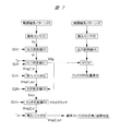
- FIG. 7 is a functional block diagram for realizing position measurement of the rack 10 and failure detection of the magnetic sensor 20 in the first embodiment
- FIG. 8 is a signal waveform input/output to/from each functional block in FIG. Is shown.
- Each signal shown in FIGS. 7 and 8 is shown at a voltage level.
- Each of the converters) 57 is an electric circuit formed inside another semiconductor chip electrically connected to the magnetic sensor 20.
- Such a semiconductor chip may be mounted inside the magnetic module 21 together with the magnetic sensor 20, or may be mounted inside an ECU (Electronic Control Unit) mounted outside the magnetic module 21. Good.
- the magnetic sensor 20 receives a magnetic signal from either the N-pole magnetic body 30N or the S-pole magnetic body 30S of the rough magnetic pattern 31.
- the magnetic sensor 20 that has received the signal outputs the sensor output signal Vs to the output reader 50.
- the output reader 50 reads the value (high level V H or low level V L ) of the sensor output signal Vs according to the read clock signal CLKr. Then, the value of the read output signal Vr (high level V H , low level V L or zero level) is output from the output reader 50 to the 0/1 determiner 51.
- the 0/1 determiner 51 determines 0 value or 1 value according to the read clock signal CLKr, passes the determination result to the ADC 57 as a 0/1 determination output signal Vdig, and the ADC 57 calculates the position of the rack 10. Is done.
- the magnetic periodic signal (trigonometric function wavelength) from the fine magnetic pattern 32 is read by the plurality of magnetic sensors 20 provided on the fine magnetic pattern 32.
- the read magnetic sensor 20 outputs an output signal to the output reader 56, and this output signal is sent to the ADC 57. Then, by integrating this result with the position of the rack 10 calculated on the side of the coarse magnetic pattern 31, the relative coordinates of the rack 10 in the coarse magnetic pattern 31 can be measured.
- the above steps are mainly related to the measurement of the position of the rack 10, but the failure of the magnetic sensor 20 is detected in the following steps.
- the 0/1 judging device 51 sends the 0/1 judging output signal Vdig to the XOR judging device 53 in accordance with the read clock signal CLKr. Further, the 0/1 determiner 51 sends the determination result of 0 value or 1 value to the first register 52 as the first register input signal Vreg1_in according to the measurement start signal Ts.
- the first register 52 sends the first register output signal Vreg1_out having the value of the first register input signal Vreg1_in to the XOR determiner 53 according to the read clock signal CLKr.
- the XOR determiner 53 determines a 0 value or a 1 value from the 0/1 determination output signal Vdig and the first register output signal Vreg1_out.
- the determination result becomes 0, and the reference voltage Vss becomes the XOR determination output signal Vxor as the latch determiner 54. Is output to.
- the XOR determiner 53 when the 0/1 determination output signal Vdig and the output signal Vreg1_out of the first register are different, the determination result is 1 and the power supply voltage Vdd is the XOR determination output signal Vxor as the latch determiner. It is output to 54.
- the latch determiner 54 outputs the second register input signal Vreg2_in to the second register 55 according to the read clock signal CLKr.
- the XOR determination output signal Vxor which is a signal input to the latch determiner 54, becomes 1 value (reference voltage Vss)
- the value of the second register input signal Vreg2_in is the value of the subsequent XOR determination output signal Vxor. It is fixed to the reference voltage Vss regardless of the result of the value.
- the second register 55 reads the second register input signal Vreg2_in according to the determination end signal Te and outputs the second register output signal Vreg2_out having the value of the second register input signal Vreg2_in.
- the second register output signal Vreg2_out has a value of 1 (reference voltage Vss)
- the magnetic sensor 20 is determined to be normal
- the second register output signal Vreg2_out has a value of 0 (power supply voltage Vdd)
- the magnetic sensor is detected. 20 is determined to be abnormal.
- the determination end signal Te is a bit of the magnetic pattern 31 of which the rack 10 is rougher adjusted than when the measurement start signal Ts is output by another on-vehicle sensor such as an angular velocity sensor, a motor angle sensor, a vehicle body position measuring camera, or GPS. This is output when it is determined that the product of the number and the bit interval is moved.
- the magnetic sensor 30 having the coarsely adjusted magnetic pattern 31 and the finely adjusted magnetic pattern 32 and the magnetic sensor 20, it is possible to accurately change the position of the rack 10. Therefore, it is possible to determine whether or not there is a failure in the magnetic sensor 20 at low cost.
- the center of the magnetic pattern 30 may be aligned with the center of the magnetic module 21 in the X direction.
- the center where they coincide is shown as center 40.
- the “case where the rack 10 is located at the initial position” described here is a case where the steering wheel 12 is located at the initial position, the steering wheel 12 is not steered, and This is the case when the angle is zero degrees.
- the angle of the wheel 3 is zero degree means that the direction of the wheel 3 is roughly parallel to the Y direction and the vehicle can go straight ahead in the forward direction.
- the angle of the wheel 3 is 10 degrees means that the direction of the wheel 3 is inclined 10 degrees from the direction parallel to the Y direction.
- the state where the angle of the wheel 3 is zero degree is a state that can frequently occur when actually driving a car. Since the center 40 of the magnetic pattern 30 coincides with the center 40 of the magnetic module 21 in a state where the angle of the wheel 3 which is frequently used is zero degree, the position of the magnetic pattern 30 and the position of the magnetic module 21 are aligned with each other. Since they are close to each other, it is possible to quickly measure the change in the position of the rack 10, and it is possible to quickly detect the failure of the magnetic sensor 20.
- the center 40 of the magnetic pattern 30 and the center 40 of the magnetic module 21 do not necessarily have to coincide with each other. That is, it is sufficient that the center 40 of the magnetic pattern 30 overlaps at least a part of the magnetic module 21 in a plan view. In other words, the center 40 of the magnetic pattern 30 may overlap with the magnetic module 21 in plan view. Even in such a case, the variation in the position of the rack 10 can be quickly measured in a state where the angle of the wheel 3 that is frequently used is zero degree, and the failure of the magnetic sensor 20 can be quickly detected. ..
- the actuator may be controlled so that the rack 10 returns to the initial position even when the rack 10 is moving while the vehicle is stopped. That is, the position of the magnetic pattern 30 may be adjusted by the actuator so that the center 40 of the magnetic pattern 30 overlaps the magnetic module 21. In this case, the variation in the position of the rack 10 can be measured more quickly when the vehicle starts next time, and the failure of the magnetic sensor 20 can be detected more quickly.
- the nonmagnetic film 33 is provided between the rack 10 and the magnetic pattern 30. That is, the nonmagnetic film 33 is provided between the rack 10 and the coarse magnetic pattern 31 and between the rack 10 and the fine magnetic pattern 32.
- the non-magnetic film 33 is provided, so that when the magnetic signal generated from the magnetic pattern 30 is read by the magnetic sensor 20, The influence of the magnetic signal generated from the rack 10 can be suppressed. Therefore, for this reason, the position of the rack 10 can be measured with high accuracy.
- the non-magnetic film 33 is made of a resin material, for example, and may be a resin containing glass fiber. Since the resin containing glass fiber has a low coefficient of linear expansion, it is unlikely that the shape of the non-magnetic film 33 changes due to a change in environmental temperature. For this reason, it is possible to suppress such a problem that the shape of the magnetic pattern 30 formed on the non-magnetic film 33 varies, so that the position of the rack 10 can be measured with high accuracy.
- the resin material forming the non-magnetic film 33 may be an elastic material. In that case, even if stress is generated between the rack 10 and the magnetic pattern 30 due to the difference in the linear expansion coefficient, it is possible to prevent problems such as damage to the magnetic pattern 30.
- the sensor substrate 22 on which the magnetic sensor 20 is arranged is formed of the same resin material as the non-magnetic film 33, the sensor substrate 22 and the non-magnetic film 33 have the same linear expansion coefficient.
- the change in ambient temperature has the effect that no stress is generated between them.
- the area of the non-magnetic film 33 is larger than the area of the magnetic pattern 30.
- the coarse magnetic pattern 31 and the fine magnetic pattern 32 are provided on the non-magnetic film 33.
- the area of the non-magnetic film 33 is equal to the area of the coarse magnetic pattern 31 and the fine magnetic pattern. It is larger than the sum of the areas of the patterns 32.
- the non-magnetic film 33 is arranged so as to include the magnetic pattern 30 in a plan view. In other words, the nonmagnetic film 33 is formed between the magnetic pattern 30 and the rack 10 so that a part of the magnetic pattern 30 does not protrude from the nonmagnetic film 33 and is not formed on the rack 10. preferable.
- the rack 10 is made of a ferromagnetic material and the area of the nonmagnetic film 33 is smaller than the area of the magnetic pattern 30, the magnetic signal read from the magnetic pattern 30 by the magnetic sensor 20 is influenced by the magnetic signal generated from the rack 10. Therefore, the accuracy of detecting the position of the rack 10 may decrease. Therefore, since the area of the non-magnetic film 33 is larger than the area of the magnetic pattern 30, such a fear can be suppressed.
- the non-magnetic film 33 is not formed on the entire rack 10 but is formed on a part of the rack 10. Specifically, the nonmagnetic film 33 is not provided on the curved portion 10b of the rack 10 but is selectively provided on the flat portion 10a of the rack 10. Therefore, in the X direction, the length of the nonmagnetic film 33 is shorter than the length of the rack 10.
- the BB cross section in the second embodiment is shown in FIG. 11, but the CC cross section in the second embodiment is the same as that in FIG. 4 of the first embodiment.
- the nonmagnetic film 33 can be easily installed.
- a fixing pin 60 that penetrates the nonmagnetic film 33 and reaches the inside of the rack 10 is provided. Since the non-magnetic film 33 is fixed to the rack 10 by the fixing pin 60, distortion due to the difference between the expansion coefficient of the rack 10 and the expansion coefficient of the non-magnetic film 33 is generated even if the environmental temperature changes. Since the non-magnetic film 33 does not occur, the position of the rack 10 can be measured with higher accuracy.
- the fixing pin 60 is provided at the center 41 of the non-magnetic film 33 in the X direction, and the fixing pin 60 is not provided at both ends of the non-magnetic film 33. If the fixing pin 60 is provided at the end of the nonmagnetic film 33, it is assumed that the shape of the nonmagnetic film 33 is deformed by ⁇ L due to expansion. Since the fixing pin 60 is provided in the center 41 of the non-magnetic film 33, the change in the shape of the non-magnetic film 33 due to expansion occurs at both ends of the non-magnetic film 33, and at each end. The shape of the nonmagnetic film 33 is deformed by ⁇ L/2. Therefore, even if the nonmagnetic film 33 is deformed, the positional deviation between the magnetic pattern 30 and the magnetic sensor 20 can be minimized.
- the center 40 of the magnetic pattern 30 is the magnetic sensor 20 in the state where the position of the rack 10 that is frequently used is the initial position (the state where the angle of the wheel 3 is zero degree), the center 40 of the magnetic pattern 30 is the magnetic sensor 20. It is desirable that they overlap, and it is more desirable that the center 40 of each of the magnetic pattern 30 and the magnetic sensor 20 be coincident with the center 41 of the nonmagnetic film 33. For this reason, as in the first modification, by using the fixing pin 60, the variation in the shape of the non-magnetic film 33 near the center 41 is reduced, so that the magnetic sensor 20 further detects the magnetic signal from the magnetic pattern 30. It can be measured with high accuracy.
- the magnetic pattern 30 including the coarse magnetic pattern 31 and the fine magnetic pattern 32 is made of a non-magnetic material such that the surface of the magnetic pattern 30 facing the magnetic sensor 20 is exposed. It is embedded inside the film 33. That is, the side surfaces and the bottom surfaces of the coarse magnetic pattern 31 and the fine magnetic pattern 32 are covered with the non-magnetic film 33 so that the surfaces of the coarse magnetic pattern 31 and the fine magnetic pattern 32 are exposed. ..
- Such a structure can be manufactured by integrally molding the magnetic pattern 30 and the nonmagnetic film 33.
- a non-magnetic film 33 in which a recess is formed, burying a powdery magnetic material in the recess, and then performing heat treatment, the magnetic pattern embedded in the recess of the non-magnetic film 33. 30 can be formed. This can reduce the manufacturing cost.
- the magnetic pattern 30 of the second embodiment can be adhered as a seal on the non-magnetic film 33, for example, but in that case, the interval between the coarse magnetic pattern 31 and the fine magnetic pattern 32 can be accurately set. There is a problem that it is difficult to match. In addition, the magnetic pattern 30 thus formed has a problem that it is easily cracked. By embedding the magnetic pattern 30 in the recess of the non-magnetic film 33 as in the second modification, these problems can be suppressed as compared with the case where the magnetic pattern 30 has a seal shape.
- a vernier type pattern is used as the absolute type magnetic pattern 30.
- a vernier magnetic pattern 34 and a vernier magnetic pattern 35 are provided on the rack 10 as the magnetic pattern 30.
- the vernier magnetic pattern 34 and the vernier magnetic pattern 35 each extend in the X direction and are arranged so as to be adjacent to each other in the Y direction orthogonal to the X direction.
- N-pole magnetic bodies 30N and S-pole magnetic bodies 30S are alternately arranged, and the length L1 of the N-pole magnetic body 30N in the X direction is the S-pole magnetic body. It is equal to the length L1 of 30S.
- N-pole magnetic bodies 30N and S-pole magnetic bodies 30S are alternately arranged, and the length L2 of the N-pole magnetic body 30N in the X direction is the S-pole magnetic body. It is equal to the length L2 of 30S.
- the length L1 is different from the length L2 and is longer than the length L2.
- the magnetic signals generated from the vernier magnetic pattern 34 and the vernier magnetic pattern 35 have wavelengths of different lengths and are measured by the magnetic sensor 20. Then, the position to which the rack 10 has moved can be obtained from the difference in the phase of the wavelength of the magnetic signal measured by each magnetic sensor 20. With such a configuration using the vernier magnetic pattern 30, the position of the rack 10 can be measured with high accuracy, and the failure of the magnetic sensor 20 can be detected.
- the center 40 of the magnetic pattern 30 overlaps with the magnetic module 21, and the center 40 of the magnetic pattern 30 and the center 40 of the magnetic module 21 should coincide with each other. It is desirable to do it. Then, the boundary between the N-pole magnetic body 30N and the S-pole magnetic body 30S in the vernier-type magnetic pattern 34 and the boundary between the N-pole magnetic body 30N and the S-pole magnetic body 30S in the vernier-type magnetic pattern 35 are It is most desirable to be located in the center 40. By arranging the vernier magnetic pattern 34 and the vernier magnetic pattern 35 in this way, the magnetic sensor 20 can measure the magnetic signal from the magnetic pattern 30 with higher accuracy.
- the technology described in the third embodiment can be applied by appropriately combining the technology described in the second embodiment.
- the detection method is a method capable of detecting a failure of the magnetic sensor 20 when the rack 10 moves by 2 bits.
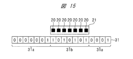
- the M-series coarse adjustment magnetic pattern 31 is connected to the first coarse adjustment magnetic region 31a in which the N-pole magnetic body 30N and the S-pole magnetic body 30S are randomly arranged, and to the first coarse adjustment magnetic region 31a. Further, the second coarse adjustment magnetic region 31b in which the N-pole magnetic body 30N and the S-pole magnetic body 30S are alternately arranged is provided. For example, when the M-sequence coarse adjustment magnetic pattern 31 has 7 bits, the coarse adjustment magnetic pattern 31 has a region of “01010” or “1010101”. In FIG. 15, such a region is shown as the second rough magnetic region 31b.
- each magnetic sensor 20 alternately detects 0 value and 1 value. That is, when the rack 10 moves by 2 bits, all the magnetic sensors 20 detect both 0 value and 1 value by the magnetic signals from the pair of N-pole magnetic body 30N and S-pole magnetic body 30S. Therefore, the failure of the magnetic sensor 20 can be detected quickly.
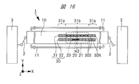
- a part of the second coarse adjustment magnetic region 31b overlaps at least a part of the magnetic module 21 in a plan view. Is desirable. In other words, it is desirable that the second coarsely adjusted magnetic region 31b overlaps with the magnetic module 21 in a plan view. Then, it is most desirable to align the center of the second coarsely adjusted magnetic region 31b with the center of the magnetic module 21 in the X direction. In FIG. 16, the center where they coincide is shown as center 42. In this way, the failure of the magnetic sensor 20 can be detected quickly.
- the technique described in the fourth embodiment can be applied by appropriately combining the techniques described in the second and third embodiments.
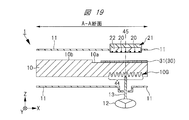
- FIG. 18 is a sectional view taken along the line AA shown in FIG. In the following, differences from the first embodiment will be mainly described.
- the magnetic pattern 30 and the magnetic module 21 straddle the center 43 of the rack 10 in the X direction. It is located in. That is, in plan view, a part of the magnetic pattern 30 and a part of the magnetic module 21 overlap with the center 43 of the rack 10 in the X direction.
- the technique described in the fifth embodiment can be applied by appropriately combining the techniques described in the second to fourth embodiments.
- the magnetic pattern 30 and the magnetic module 21 are arranged so as to straddle the center 45 of the rack tooth formation region 44 in which the plurality of rack teeth 10G are formed in the X direction.
- a part of the magnetic pattern 30 and a part of the magnetic module 21 overlap the center 45 of the rack tooth formation region 44 in the X direction.
- the shaft 13 is provided near the center 45 of the rack tooth formation region 44. Then, a part of the housing 11 is processed according to the shape of the shaft 13.
- the magnetic module 21 is provided as a part of the housing 11. Therefore, it is not necessary to process other regions of the housing 11 by bringing the regions of the housing 11 to be processed closer to each other. For example, a part of the housing 11 that is a region where the shaft 13 and the magnetic module 21 are formed is manufactured first, and another part of the housing 11 that is parallel to the rack 10 is manufactured later.
- the housing 11 can also be formed by joining together. In such a case, if the technique of the sixth embodiment is used, the steering device 1 can be easily manufactured.
- the technique described in the sixth embodiment can be applied by appropriately combining the techniques described in the second to fifth embodiments.
- the steering wheel 12 and the shaft 13 are arranged near the center 43 of the rack 10 for a single passenger.
- An example is a car.
- the magnetic pattern 30 is a magnetic pattern different from the coarse magnetic pattern 31 and the fine magnetic pattern 32, and also has the abnormality detection pattern 31c for the magnetic sensor 20.
- the abnormality detection pattern 31c has a structure in which N-pole magnetic bodies 30N and S-pole magnetic bodies 30S are alternately arranged. However, in the X direction, the lengths of the N-pole magnetic body 30N and the S-pole magnetic body 30S of the abnormality detection pattern 31c are the same as the N-pole magnetic body 30N and the S-pole magnetic body of the rough magnetic pattern 31. Shorter than each 30S length. That is, the pitch of the abnormality detection pattern 31c is shorter than the pitch of the coarse magnetic pattern 31.
- the abnormality detection pattern 31c is formed on the surface of the rough magnetic pattern 31.
- Such an abnormality detection pattern 31c can be formed, for example, by changing the magnetism of the surface of the rough magnetic pattern 31.
- FIG. 22 shows a waveform of a magnetic signal detected by the magnetic sensor 20 in the seventh embodiment.
- the waveform shown in FIG. 22 is an example of a composite waveform in which the waveform of the magnetic signal from the coarsely-adjusted magnetic pattern 31 and the waveform of the magnetic signal of the abnormality detection pattern 31c are superimposed, and for example, the sensor output signal Vs And the waveform of the magnetic signal of the abnormality detection pattern 31c.
- the waveform of the magnetic signal from the coarse magnetic pattern 31 and the concave-convex waveform having a pitch shorter than the pitch of the waveform of the magnetic signal from the coarse magnetic pattern 31 are superimposed.
- such a synthetic waveform is generated from the rough magnetic pattern 31 and has the first waveform having a long wavelength, and is generated from the abnormality detection pattern 31c, and has a wavelength shorter than the first waveform.
- the second waveform is the synthesized waveform.
- the magnetic sensor 20 when a certain magnetic sensor 20 detects both a concave portion and a convex portion having a short pitch in the magnetic signal having such a composite waveform, it is determined that the magnetic sensor 20 is not defective.
- the magnetic sensor 20 by using the magnetic signal of such a composite waveform, the magnetic sensor 20 can be used even if the moving distance of the rack 10 is very short and detection is difficult only with the magnetic signal from the rough magnetic pattern 31. The failure can be detected quickly.
- the abnormality detection pattern 31c is formed on the entire surface of the coarse adjustment magnetic pattern 31.
- the abnormality detection pattern 31c is one of the surfaces of the coarse adjustment magnetic pattern 31. It may be formed in the part.
- the abnormality detection pattern 31c may also be formed on the fine magnetic pattern 32.
- the abnormality detection pattern 31c may be formed in a region different from the coarse magnetic pattern 31 and the fine magnetic pattern 32.
- the abnormality detection pattern 31c may be independently formed in a region between the coarse magnetic pattern 31 and the fine magnetic pattern 32.
- the technique described in the seventh embodiment can be applied by appropriately combining the techniques described in the second to sixth embodiments.
Landscapes
- Physics & Mathematics (AREA)
- General Physics & Mathematics (AREA)
- Engineering & Computer Science (AREA)
- Chemical & Material Sciences (AREA)
- Combustion & Propulsion (AREA)
- Transportation (AREA)
- Mechanical Engineering (AREA)
- Measurement Of Length, Angles, Or The Like Using Electric Or Magnetic Means (AREA)
- Power Steering Mechanism (AREA)
Abstract
ステアリング装置の性能を向上させる。ステアリング装置1のハウジング11の内部には、X方向に移動可能なラック10が設けられ、ラック10上には、複数のN極の磁性体30Nおよび複数のS極の磁性体30Sを有する磁気パターン30が形成されている。また、ハウジング11には、磁気センサ20を有する磁気モジュール21が取り付けられている。磁気パターン30からの磁気信号を磁気センサ20で受信することで、ラック10の移動の変動を高精度に測定することができ、磁気センサ20の故障を検知することができる。
Description
本発明は、ステアリング装置に関し、特に、磁気センサを有するステアリング装置に好適に利用できるものである。
近年、自動車のような乗り物において、自動運転の実用化を促進させるため、タイヤ角(車輪の角度)を制御する必要がある。そして、タイヤ角を高精度に制御するため、タイヤ角を高精度に測定する必要がある。
例えば、特許文献1には、ステアリング装置において、ステアリングホイール(ハンドル)の回転角からタイヤ角を測定する技術が開示されている。ここでは、ステアリングホイールを回転させることで、ギアを介してラックが水平方向に移動し、このラックの水平移動がタイヤ角を変動させる。このため、ステアリングホイールの回転角を測定すれば、タイヤ角を知ることができる。
また、特許文献2には、ラック上に磁気マークを形成し、この磁気マークを磁気センサで読み取ることで、ラックが中立位置に位置することを検知する技術が開示されている。
しかしながら、特許文献1に開示されている技術では、ギアとラックとの間にバックラッシュが生じる。従って、ギアの回転角を測定した場合、ラックの位置を高精度に測定することができず、タイヤ角を高精度に測定することができないという問題が生じる。また、特許文献2に開示されている技術は、ラックの中立位置を検知するのみであり、タイヤ角の変動を正確に測定することができない。そこで、ステアリング装置内に、例えば磁気センサのような位置検知用の素子を配置させた際に、ラックの位置を高精度に測定する技術が求められる。
また、仮に磁気センサに故障が発生すると、ラックの位置を高精度に測定することが困難となる。そこで、安全な自動運転を実現するために、磁気センサの故障を素早く検知する技術が求められる。磁気センサの故障を検知するための従来技術の一例としては、磁気センサの周囲にコイルを配置した半導体チップを用いる方法がある。この方法では、内蔵コイルに流す電流を変えることで発生する磁界を制御し、その磁界の変化を正常に検知することが可能か否かにより、磁気センサの故障の有無が判定される。しかしながら、このような磁気センサおよび内蔵コイルを有する半導体チップは、高価であり、製造コストが増加するという問題がある。
その他の課題と新規な特徴は、本明細書の記述および添付図面から明らかになるであろう。
本願において開示される実施の形態のうち、代表的なものの概要を簡単に説明すれば、次のとおりである。
一実施の形態であるステアリング装置は、ハウジングと、ハウジングの内部に設けられ、且つ、第1方向に移動可能なラックと、ラック上に形成され、且つ、複数のN極の磁性体および複数のS極の磁性体を有する磁気パターンと、ハウジングに取り付けられ、且つ、磁気パターンからの磁気信号を検知するための磁気センサとを有する。
本願において開示される実施の形態によれば、ステアリング装置の性能を向上させることができる。
以下、本発明の実施の形態を図面に基づいて詳細に説明する。なお、実施の形態を説明するための全図において、同一の機能を有する部材には同一の符号を付し、その繰り返しの説明は省略する。また、以下の実施の形態では、特に必要なときを除き、同一または同様な部分の説明を原則として繰り返さない。
(実施の形態1)
図1は、本実施の形態の自動車のような乗り物のステアリング装置1の平面図であり、図2は、図1のA-A線に沿った断面図であり、図3は、図1のB-B線に沿った断面図であり、図4は、図1のC-C線に沿った断面図である。なお、図1は平面図であるが、図面を見易くするため、磁気パターン30に含まれるN極の磁性体30NおよびS極の磁性体30Sにハッチングが付されている。なお、以降で説明する他の平面図でも同様に、N極の磁性体30NおよびS極の磁性体30Sにハッチングが付されている。
図1は、本実施の形態の自動車のような乗り物のステアリング装置1の平面図であり、図2は、図1のA-A線に沿った断面図であり、図3は、図1のB-B線に沿った断面図であり、図4は、図1のC-C線に沿った断面図である。なお、図1は平面図であるが、図面を見易くするため、磁気パターン30に含まれるN極の磁性体30NおよびS極の磁性体30Sにハッチングが付されている。なお、以降で説明する他の平面図でも同様に、N極の磁性体30NおよびS極の磁性体30Sにハッチングが付されている。
図1~図3に示されるように、ステアリング装置1は、ハウジング11、ハウジング11の内部に設けられているラック(ロッド)10、ラック10上に形成された磁気パターン30、ハウジング11に取り付けられた磁気モジュール21、ステアリングホイール(ハンドル)12、および、ラック10とステアリングホイール12とを繋ぐシャフト13を有する。
ステアリング装置1では、ステアリングホイール12を回転させることで、ステアリングホイール12に接続されているシャフト13が回転する。詳細に図示はしていないが、シャフト13の先端には、シャフト13の一部の部材として歯車状のピニオンが備えられており、シャフト13の回転によって、シャフト13のピニオンと、ラック10に形成されたラック歯10Gとが噛み合い、ラック10はX方向(ラック10の長手方向または移動方向)に移動する。そして、ラック10の移動によって、タイロッド2を介して、車輪3の角度が変動する。すなわち、ステアリングホイール12の角度を変動させることで、X方向に移動可能なラック10の位置が変動し、車輪3の角度が変動する。
例えば、本実施の形態では、ラック10がX方向に±10cm程度移動した場合、車輪3の角度の変動は±20度程度となり、ステアリングホイール12の角度の変動は±334度程度となる。また、ステアリングホイール12の角度の誤差が±0.1度程度であった場合、ラック10のX方向の位置の誤差は±30μm程度となり、車輪3の角度の誤差は±0.006度程度となる。
上述のように、自動車分野においては、自動運転の技術を向上させることが求められており、車輪3の角度を高精度に制御することが求められている。そこで、本願発明者らは、ステアリング装置1内に磁気センサ20のような位置検知用の素子を配置することで、ラック10の位置を高精度に測定し、車輪3の角度を高精度に測定することに着目した。特に、本願発明者らは、ステアリング装置1内に、磁気パターン30と、複数の磁気センサ20を有する磁気モジュール21と備える磁気式リニアエンコーダによって、ラック10の位置を高精度に測定することに着目した。
図1に示されるように、本実施の形態のラック10上には、複数のN極の磁性体30Nおよび複数のS極の磁性体30Sを有する磁気パターン30が形成されている。磁気パターン30の厚さは、例えば1mmである。磁気パターン30は、ラック10の絶対座標を検出できるアブソリュートタイプであり、粗調磁気パターン31および微調磁気パターン32を有する。平面視において、粗調磁気パターン31および微調磁気パターン32は、それぞれX方向に延在し、X方向と直交するY方向で互いに隣接するように配置されている。
本実施の形態の粗調磁気パターン31では、N極の磁性体30NおよびS極の磁性体30Sは、nビットの不規則乱数コードのパターン(M系列のパターン)を構成している。なお、粗調磁気パターン31におけるN極の磁性体30NおよびS極の磁性体30Sは、他のパターンであっても良い。また、本実施の形態の微調磁気パターン32では、N極の磁性体30NとS極の磁性体30Sとが交互に配置されている。なお、本実施の形態では、粗調磁気パターン31が7ビットであり、粗調磁気パターン31上に7個の磁気センサ20が設けられている場合を例示し、微調磁気パターン32上に4個の磁気センサ20が設けられている場合を例示している。また、各々のビット数および磁気センサ20の数は、適宜変更することができる。
図2および図3に示されるように、磁気モジュール21は、センサ基板22に取り付けられた複数の磁気センサ20を含み、各々の磁気センサ20がハウジング11と磁気パターン30との間に位置するように、ハウジング11に固定されている。すなわち、磁気モジュール21は、ハウジング11の一部を構成し、磁気モジュール21に含まれている磁気センサ20は、ハウジング11の一部に用いられる部材として、ハウジング11に取り付けられている。
また、各々の磁気センサ20は、磁気パターン30からの磁気信号を受信することができる。具体的には、nビットの粗調磁気パターン31からの磁気信号を、粗調磁気パターン31上に設けられているn個の磁気センサ20によって読み取ることで、ラック10の絶対座標をミリメートル(mm)オーダで測定することができる。また、微調磁気パターン32からの磁気的周期信号(三角関数波長)を、微調磁気パターン32上に設けられている複数の磁気センサ20によって読み取ることで、粗調磁気パターン31内におけるラック10の相対的な座標をマイクロメートル(μm)オーダで測定することができる。
このように、磁気パターン30および複数の磁気センサ20によって、ステアリング装置1内に磁気式リニアアブソリュートエンコーダが形成されている。従って、本実施の形態では、X方向におけるラック10の絶対座標を高精度に測定することができ、その結果から、車輪3の角度を高精度に検出することができる。すなわち、本実施の形態では、ステアリング装置1の性能を向上させることができる。
また、図2~図4に示されるように、ラック10は、概ね円柱状の構造を成しているが、ラック10がシャフト13に接続される箇所では、ラック10に加工が施されており、複数のラック歯10Gが形成されている。そして、ラック10は、複数のラック歯10Gが形成されている以外の領域において、平坦部10aおよび曲部10bを有する。
例えば、磁気パターン30が平坦部10a上と曲部10b上とに跨って形成されている場合、磁気パターン30から発生する磁力線の向きおよび磁力にばらつき生じ、磁気センサ20で正しく磁気信号を検知できない恐れがある。本実施の形態では、図3に示されるように、粗調磁気パターン31および微調磁気パターン32を含む磁気パターン30は、ラック10の平坦部10a上に形成されており、ラック10の曲部10b上に形成されていない。このため、上記の恐れを抑制することができる。すなわち、磁気パターン30の全体が、ラック10の平坦部10a上に形成されていることが望ましい。
<磁気センサ20の故障検知について>
磁気式リニアアブソリュートエンコーダでは、磁気センサ20が故障すると、ラック10の位置を高精度に測定することが困難となる。そこで、安全な自動運転を実現するためには、磁気センサ20の故障を素早く検知する必要がある。以下に、図6~図9を用いて、本実施の形態のステアリング装置1において、磁気センサ20の故障を検知する方法を説明する。
磁気式リニアアブソリュートエンコーダでは、磁気センサ20が故障すると、ラック10の位置を高精度に測定することが困難となる。そこで、安全な自動運転を実現するためには、磁気センサ20の故障を素早く検知する必要がある。以下に、図6~図9を用いて、本実施の形態のステアリング装置1において、磁気センサ20の故障を検知する方法を説明する。
図6は、磁気センサ20が磁気パターン30からの磁気信号を受信する例を示す模式図である。ここでは、7ビットのM系列コードからなる粗調磁気パターン31からの磁気信号を、7個の磁気センサ20で読み取る場合について説明する。
まず、本願発明者らは、磁気センサ20が故障している時、磁気センサ20からの出力信号が0値または1値に固定されている場合が多いことに着目した。以下の説明では、磁気センサ20からの異なる2つの出力信号のうち、一方が0値であり、他方が1値であるとして説明する。なお、磁気センサ20がホールスイッチのようなセンサである場合には、出力信号として1値または-1値が出力されるが、ここでは、1値または-1値のうち、一方が0値であり、他方が1値であるとして説明する。
図6に示されるように、「移動前」の位置にあった粗調磁気パターン31が、ラック10の移動に伴って「移動後」の位置まで移動したとする。そして、M系列の粗調磁気パターン31のビット数が7ビットであるとする。この場合、粗調磁気パターン31が7ビット分移動すると、各々の磁気センサ20は、少なくとも1つのN極の磁性体30Nおよび少なくとも1つのS極の磁性体30Sからの磁気信号を受信するので、各々の磁気センサ20は、0値および1値の両方を少なくとも1回検知することになる。
そこで、本実施の形態では、粗調磁気パターン31のビット数とビット間隔との積の距離をラック10が動く間に、各々の磁気センサ20が、0値および1値の両方を少なくとも1回検知するか否かを以て、各磁気センサ20が故障しているか否かを判定する。すなわち、磁気センサ20が0値および1値の両方を出力した場合、その磁気センサ20は正常であると判定され、磁気センサ20が0値または1値の何れか一方のみを出力した場合、その磁気センサ20は故障であると判定される。
ここで、粗調磁気パターン31のビット数とビット間隔との積の距離をラック10が移動したか否かは、自動車に取り付けられた他の車載センサからの出力信号を用いることで、判定することができる。そのような他の車載センサとしては、例えば、角速度センサ、モータ角センサ、車体位置測定カメラまたはGPSなどが挙げられる。このような構成によれば、磁気センサ20および内蔵コイルを有する半導体チップを用いなくても、磁気センサ20の故障を検知することができる。
図7は、実施の形態1において、ラック10の位置測定および磁気センサ20の故障検知を実現するための機能ブロック図であり、図8は、図7における各機能ブロックに入出力される信号波形を示している。なお、図7および図8に示される各信号は、電圧レベルで示されている。また、図7に示される出力読取器50、0/1判定器51、第1レジスタ52、XOR判定器53、ラッチ判断器54、第2レジスタ55、出力読取器56およびADC(アナログ・デジタル・コンバータ)57は、それぞれ、磁気センサ20に電気的に接続された他の半導体チップの内部に形成されている電気回路である。そして、このような半導体チップは、磁気センサ20と共に磁気モジュール21の内部に搭載されていてもよいし、磁気モジュール21の外部に取り付けられているECU(Electronic Control Unit)の内部に搭載されていてもよい。
まず、粗調磁気パターン31のうちN極の磁性体30NまたはS極の磁性体30Sの何れかからの磁気信号を、磁気センサ20が受信する。受信を行った磁気センサ20は、センサ出力信号Vsを出力読取器50へ出力する。
次に、出力読取器50は、読取クロック信号CLKrに従って、センサ出力信号Vsの値(ハイレベルVHまたはローレベルVL)を読取る。その後、読取出力信号Vrの値(ハイレベルVH、ローレベルVLまたはゼロレベル)を、出力読取器50から0/1判定器51へ出力する。
次に、0/1判定器51は、読取クロック信号CLKrに従って0値または1値の判定を行い、この判定結果を0/1判定出力信号VdigとしてADC57に渡し、ADC57においてラック10の位置の算出が行われる。
一方で、微調磁気パターン32からの磁気的周期信号(三角関数波長)を、微調磁気パターン32上に設けられている複数の磁気センサ20によって読み取る。読み取りを行った磁気センサ20は、出力信号を出力読取器56へ出力し、この出力信号はADC57へ送られる。そして、この結果を、粗調磁気パターン31側で算出されたラック10の位置に統合することで、粗調磁気パターン31内におけるラック10の相対的な座標を測定することができる。
以上のステップは、主に、ラック10の位置の測定に関するが、以降のステップによって、磁気センサ20の故障検知が行われる。
0/1判定器51は、読取クロック信号CLKrに従って0/1判定出力信号VdigをXOR判定器53へ送る。また、0/1判定器51は、測定開始信号Tsに従って、0値または1値の判定結果を第1レジスタ入力信号Vreg1_inとして第1レジスタ52へ送る。
次に、第1レジスタ52は、読取クロック信号CLKrに従って、第1レジスタ入力信号Vreg1_inの値を有する第1レジスタ出力信号Vreg1_outをXOR判定器53へ送る。
次に、XOR判定器53は、0/1判定出力信号Vdigおよび第1レジスタ出力信号Vreg1_outから、0値または1値を判定する。XOR判定器53において、0/1判定出力信号Vdigと第1レジスタの出力信号Vreg1_outとが等しい場合には、判定結果が0値となり、基準電圧Vssが、XOR判定出力信号Vxorとしてラッチ判断器54へ出力される。また、XOR判定器53において、0/1判定出力信号Vdigと第1レジスタの出力信号Vreg1_outとが異なる場合は、判定結果が1値となり、電源電圧Vddが、XOR判定出力信号Vxorとしてラッチ判断器54へ出力される。
次に、ラッチ判断器54は、読取クロック信号CLKrに従って、第2レジスタ入力信号Vreg2_inを第2レジスタ55へ出力する。ここで、ラッチ判断器54に入力する信号であるXOR判定出力信号Vxorが1値(基準電圧Vss)となった段階で、第2レジスタ入力信号Vreg2_inの値は、以後のXOR判定出力信号Vxorの値の結果に関わらず、基準電圧Vssに固定される。
次に、第2レジスタ55は、判定終了信号Teに従って第2レジスタ入力信号Vreg2_inを読取り、第2レジスタ入力信号Vreg2_inの値を有する第2レジスタ出力信号Vreg2_outを出力する。ここで、第2レジスタ出力信号Vreg2_outが1値(基準電圧Vss)の場合、磁気センサ20は正常であると判定され、第2レジスタ出力信号Vreg2_outが0値(電源電圧Vdd)の場合、磁気センサ20は異常であると判定される。
以上の動作を、他のN極の磁性体30Nまたは他のS極の磁性体30Sの各々に対応する磁気センサ20に対して行うことで、全ての磁気センサ20が故障しているか否かの判定を行うことができる。
なお、判定終了信号Teは、角速度センサ、モータ角センサ、車体位置測定カメラ、またはGPSなどのような他の車載センサによって、測定開始信号Ts出力時よりもラック10が粗調磁気パターン31のビット数とビット間隔との積の距離を移動した、と判定された場合に出力される。
また、上記の説明は、粗調磁気パターン31に用いられる磁気センサ20の故障を判定する場合について行ったが、微調磁気パターン32に用いられる磁気センサ20の故障を判定する場合についても、同様の手法で行うことができる。
以上のように、本実施の形態のステアリング装置1では、粗調磁気パターン31および微調磁気パターン32を有する磁気パターン30と、磁気センサ20とを用いることで、ラック10の位置の変動を高精度に測定することができ、磁気センサ20の故障の有無を低コストで判定することができる。
また、図5に示されるように、ラック10が初期位置に位置している場合、X方向において、磁気パターン30の中央と、磁気モジュール21の中央とを一致させてもよい。図5では、これらが一致している中央は、中央40として示されている。
なお、ここで説明している「ラック10が初期位置に位置している場合」とは、ステアリングホイール12が初期位置に位置している場合であり、ステアリングホイール12が操舵されず、車輪3の角度がゼロ度の場合である。また、「車輪3の角度がゼロ度」とは、車輪3の向きが、Y方向と粗平行であり、自動車の前方向に直進できる状態を意味する。例えば、「車輪3の角度が10度」とは、車輪3の向きがY方向と平行な方向から10度傾いている状態を意味する。
このような車輪3の角度がゼロ度の状態は、自動車を実際に運転する際に頻繁に起こり得る状態である。使用頻度の高い車輪3の角度がゼロ度の状態において、磁気パターン30の中央40が、磁気モジュール21の中央40と一致していることにより、磁気パターン30の位置と磁気モジュール21の位置とが近いので、ラック10の位置の変動を迅速に測定することができ、磁気センサ20の故障の検知を迅速に行うことができる。
また、ラック10が初期位置に位置している場合に、磁気パターン30の中央40と、磁気モジュール21の中央40とが必ずしも一致していなくともよい。すなわち、平面視において、磁気パターン30の中央40が、少なくとも磁気モジュール21の一部と重なっていればよい。言い換えれば、平面視において、磁気パターン30の中央40は、磁気モジュール21とオーバーラップしていればよい。このような場合でも、使用頻度の高い車輪3の角度がゼロ度の状態で、ラック10の位置の変動を迅速に測定することができ、磁気センサ20の故障の検知を迅速に行うことができる。
しかしながら、磁気センサ20の故障の検知に最も有効であるのは、上述のように、磁気パターン30の中央40が、磁気モジュール21の中央40と一致している状態である。
また、自動車が停車した状態において、ラック10が移動していた場合でも、ラック10が初期位置に戻るように、アクチュエータを制御してもよい。すなわち、アクチュエータによって、磁気パターン30の中央40が磁気モジュール21とオーバーラップするように、磁気パターン30の位置を調整してもよい。この場合、次回の自動車の発車時に、ラック10の位置の変動を更に迅速に測定することができ、磁気センサ20の故障の検知を更に迅速に行うことができる。
(実施の形態2)
以下に、実施の形態2のステアリング装置1を、図9~図11を用いて説明する。図9~図11は、それぞれ実施の形態1の図1~図3に対応する図面である。なお、以下では、実施の形態1との相違点を主に説明する。
以下に、実施の形態2のステアリング装置1を、図9~図11を用いて説明する。図9~図11は、それぞれ実施の形態1の図1~図3に対応する図面である。なお、以下では、実施の形態1との相違点を主に説明する。
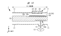
図9~図11に示されるように、実施の形態2では、ラック10と磁気パターン30との間に、非磁性体膜33が設けられている。すなわち、ラック10と粗調磁気パターン31との間、および、ラック10と微調磁気パターン32との間に、非磁性体膜33が設けられている。
例えば、ラック10が、強磁性体によって構成されている場合であっても、非磁性体膜33が設けられていることによって、磁気パターン30から発生する磁気信号を磁気センサ20によって読み取る際に、ラック10から発生する磁気信号の影響を抑制することができる。従って、このため、ラック10の位置を高精度に測定することができる。
非磁性体膜33は、例えば樹脂材料からなり、ガラス繊維を含む樹脂であってもよい。ガラス繊維を含む樹脂は線膨張係数が低いので、環境温度の変化によって、非磁性体膜33の形状が変化する恐れが低い。このため、非磁性体膜33の上に形成される磁気パターン30の形状がばらつくなどの不具合を抑制することができるので、ラック10の位置を高精度に測定することができる。
また、非磁性体膜33を構成する樹脂材料は、弾性材料であっても良い。その場合、線膨張係数の違いによって、ラック10と磁気パターン30との間に応力が生じても、磁気パターン30が破損するなどの不具合を防止することができる。
また、磁気センサ20が配置されるセンサ基板22が、非磁性体膜33と同じ樹脂材料で形成されている場合、センサ基板22および非磁性体膜33の各々の線膨張係数が等しくなるので、環境温度の変化によって、互いの間に応力が生じないという効果が得られる。
また、非磁性体膜33の面積は、磁気パターン30の面積よりも大きい。具体的には、非磁性体膜33上には、粗調磁気パターン31および微調磁気パターン32が設けられているが、非磁性体膜33の面積は、粗調磁気パターン31の面積と微調磁気パターン32の面積との和よりも大きい。また、平面視において、非磁性体膜33は、磁気パターン30を内包するように配置されていることが好ましい。言い換えれば、磁気パターン30の一部が、非磁性体膜33からはみ出し、ラック10上に形成されないように、磁気パターン30とラック10との間に非磁性体膜33が形成されていることが好ましい。
仮に、ラック10が強磁性体からなり、非磁性体膜33の面積が磁気パターン30の面積より小さい場合、磁気センサ20が磁気パターン30から読み取る磁気信号が、ラック10から発生する磁気信号の影響を受ける恐れがあるため、ラック10の位置の検出精度が低下する恐れがある。従って、非磁性体膜33の面積が、磁気パターン30の面積よりも大きいことで、このような恐れを抑制することができる。
また、非磁性体膜33は、ラック10全体に形成されておらず、ラック10の一部に形成されている。具体的には、非磁性体膜33は、ラック10の曲部10bに設けられておらず、ラック10の平坦部10aに選択的に設けられている。このため、X方向において、非磁性体膜33の長さは、ラック10の長さよりも短い。
実施の形態2におけるB-B断面は、図11に示されているが、実施の形態2におけるC-C断面は、実施の形態1の図4と同じである。このように、非磁性体膜33を曲部10bではなく平坦部10aに設けることで、非磁性体膜33の設置が容易となる。
(実施の形態2の変形例1)
以下に、実施の形態2の変形例1のステアリング装置1を、図12を用いて説明する。なお、以下では、実施の形態2との相違点を主に説明する。
以下に、実施の形態2の変形例1のステアリング装置1を、図12を用いて説明する。なお、以下では、実施の形態2との相違点を主に説明する。
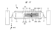
図12に示されるように、変形例1では、非磁性体膜33を貫通し、ラック10の内部に到達する固定ピン60が設けられている。固定ピン60によって非磁性体膜33がラック10に固定されていることで、環境温度の変化があったとしても、ラック10の膨張係数と非磁性体膜33の膨張係数との差による歪が、非磁性体膜33に発生しないため、ラック10の位置をより高精度に測定することができる。
また、固定ピン60は、X方向における非磁性体膜33の中央41に設けられており、非磁性体膜33の両端部には固定ピン60は設けられていない。仮に、固定ピン60を非磁性体膜33の端部に設けた場合、膨張によって非磁性体膜33の形状がΔL分だけ変形したとする。固定ピン60が非磁性体膜33の中央41に設けられていることによって、膨張によって非磁性体膜33の形状の変動は、非磁性体膜33の両端部で発生し、両端部における各々の非磁性体膜33の形状は、ΔL/2分だけ変形する。従って、仮に、非磁性体膜33が変形したとしても、磁気パターン30と磁気センサ20との位置ずれを最小限にすることができる。
更に、実施の形態1で説明したような、使用頻度の高いラック10の位置が初期位置である状態(車輪3の角度がゼロ度の状態)において、磁気パターン30の中央40が磁気センサ20とオーバーラップしていることが望ましく、磁気パターン30および磁気センサ20の各々の中央40が、非磁性体膜33の中央41と一致していることがより望ましい。このため、変形例1のように、固定ピン60を用いて、中央41付近における非磁性体膜33の形状の変動が小さくなることによって、磁気センサ20は、磁気パターン30からの磁気信号をより高精度に測定することができる。
(実施の形態2の変形例2)
以下に、実施の形態2の変形例2のステアリング装置1を、図13を用いて説明する。なお、以下では、実施の形態2との相違点を主に説明する。
以下に、実施の形態2の変形例2のステアリング装置1を、図13を用いて説明する。なお、以下では、実施の形態2との相違点を主に説明する。
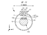
図13に示されるように、変形例2では、粗調磁気パターン31および微調磁気パターン32を含む磁気パターン30が、磁気センサ20に対向する磁気パターン30の表面が露出するように、非磁性体膜33の内部に埋め込まれている。すなわち、粗調磁気パターン31および微調磁気パターン32の各々の表面が露出するように、粗調磁気パターン31および微調磁気パターン32の各々の側面および底面は、非磁性体膜33によって覆われている。
このような構造は、磁気パターン30と非磁性体膜33とを一体成型することで製造できる。例えば、凹部が形成されている非磁性体膜33を用意し、凹部内に粉末状の磁性体を埋め込み、その後、熱処理を施すことで、非磁性体膜33の凹部内に埋め込まれた磁気パターン30を形成することができる。これによって、製造コストを低下させることができる。
また、実施の形態2の磁気パターン30は、例えば非磁性体膜33上にシールとして張り合わせることもできるが、その場合、粗調磁気パターン31と微調磁気パターン32との間の間隔を精度良く合わせることが難しいという問題がある。また、このように形成された磁気パターン30は、割れ易いという問題もある。変形例2のように、非磁性体膜33の凹部内に磁気パターン30を埋め込むことで、磁気パターン30がシール状であった場合と比較して、これらの問題を抑制することができる。
なお、変形例2で説明した技術に、変形例1で説明した技術を適宜組み合わせて適用することもできる。
(実施の形態3)
以下に、実施の形態3のステアリング装置1を、図14を用いて説明する。なお、以下では、実施の形態1との相違点を主に説明する。
以下に、実施の形態3のステアリング装置1を、図14を用いて説明する。なお、以下では、実施の形態1との相違点を主に説明する。
実施の形態3では、アブソリュートタイプの磁気パターン30として、バーニア型のパターンが用いられている。
図14に示されるように、ラック10上には、磁気パターン30として、バーニア型磁気パターン34およびバーニア型磁気パターン35の2つのパターンが設けられている。平面視において、バーニア型磁気パターン34およびバーニア型磁気パターン35は、それぞれX方向に延在し、X方向と直交するY方向で互いに隣接するように配置されている。
バーニア型磁気パターン34では、N極の磁性体30NとS極の磁性体30Sとが交互に配置されており、X方向において、N極の磁性体30Nの長さL1は、S極の磁性体30Sの長さL1と等しい。バーニア型磁気パターン35では、N極の磁性体30NとS極の磁性体30Sとが交互に配置されており、X方向において、N極の磁性体30Nの長さL2は、S極の磁性体30Sの長さL2と等しい。ここで、長さL1は、長さL2と異なっており、長さL2よりも長い。
実施の形態3では、バーニア型磁気パターン34およびバーニア型磁気パターン35から発生する磁気信号の各々は、異なる長さの波長を有し、磁気センサ20で測定される。そして、各々の磁気センサ20において測定された磁気信号の波長の位相の違いから、ラック10が移動した位置を求めることができる。このようなバーニア型の磁気パターン30を用いた構成によっても、ラック10位置を高精度に測定することができ、磁気センサ20の故障の検知を行うことができる。
また、ラック10の位置が初期位置である状態において、磁気パターン30の中央40が磁気モジュール21とオーバーラップしていることが望ましく、磁気パターン30の中央40が、磁気モジュール21の中央40と一致していることが望ましい。そして、バーニア型磁気パターン34におけるN極の磁性体30NとS極の磁性体30Sとの境界、および、バーニア型磁気パターン35におけるN極の磁性体30NとS極の磁性体30Sとの境界が、中央40に位置していることが、最も望ましい。このようにバーニア型磁気パターン34およびバーニア型磁気パターン35を配置することで、磁気センサ20は、磁気パターン30からの磁気信号をより高精度に測定することができる。
なお、実施の形態3で説明した技術に、実施の形態2で説明した技術を適宜組み合わせて適用することもできる。
(実施の形態4)
以下に、実施の形態4のステアリング装置1を、図15および図16を用いて説明する。なお、以下では、実施の形態1との相違点を主に説明する。
以下に、実施の形態4のステアリング装置1を、図15および図16を用いて説明する。なお、以下では、実施の形態1との相違点を主に説明する。
実施の形態4では、磁気センサ20の故障を検知するために、実施の形態1と同じM系列の粗調磁気パターン31を用いるが、粗調磁気パターン31のうち、実施の形態1とは異なる領域を用いる。また、ここでの検知方法は、ラック10が2ビット分移動した際に、磁気センサ20の故障を検知することができる方法である。
M系列の粗調磁気パターン31は、N極の磁性体30NとS極の磁性体30Sとがランダムに配置された第1粗調磁気領域31a、および、第1粗調磁気領域31aに接続され、且つ、N極の磁性体30NとS極の磁性体30Sとが交互に配置された第2粗調磁気領域31bが設けられている。例えば、M系列の粗調磁気パターン31が7ビットである場合、粗調磁気パターン31には、「0101010」または「1010101」となる領域が存在する。図15では、このような領域が第2粗調磁気領域31bとして示されている。
このため、第2粗調磁気領域31bにおいて、各々の磁気センサ20では、0値および1値が交互に検知される。すなわち、ラック10が2ビット分移動した際に、全ての磁気センサ20は、一対のN極の磁性体30NおよびS極の磁性体30Sからの磁気信号によって、0値および1値の両方を検知することになるので、磁気センサ20の故障の検知を迅速に行うことができる。
また、図16に示されるように、ラック10が初期位置に位置している場合、平面視において、第2粗調磁気領域31bの一部が、少なくとも磁気モジュール21の一部と重なっていることが望ましい。言い換えれば、平面視において、第2粗調磁気領域31bは、磁気モジュール21とオーバーラップしていることが望ましい。そして、X方向において、第2粗調磁気領域31bの中央と、磁気モジュール21の中央とを一致させることが最も望ましい。図16では、これらが一致している中央は、中央42として示されている。このようにして、磁気センサ20の故障の検知を迅速に行うことができる。
なお、実施の形態4で説明した技術に、実施の形態2および実施の形態3で説明した技術を適宜組み合わせて適用することもできる。
(実施の形態5)
以下に、実施の形態5のステアリング装置1を、図17および図18を用いて説明する。図18は、図17に示されるA-A線に沿った断面図である。なお、以下では、実施の形態1との相違点を主に説明する。
以下に、実施の形態5のステアリング装置1を、図17および図18を用いて説明する。図18は、図17に示されるA-A線に沿った断面図である。なお、以下では、実施の形態1との相違点を主に説明する。
図17および図18に示されるように、実施の形態5では、ラック10が初期位置に位置している場合、X方向において、磁気パターン30および磁気モジュール21が、ラック10の中央43を跨ぐように配置されている。すなわち、平面視において、磁気パターン30の一部および磁気モジュール21の一部が、X方向におけるラック10の中央43と重なっている。このように磁気パターン30および磁気モジュール21を配置したことによって、ラック10の位置の測定をより高精度に行うことができる。
なお、実施の形態5で説明した技術に、実施の形態2~4で説明した技術を適宜組み合わせて適用することもできる。
(実施の形態6)
以下に、実施の形態6のステアリング装置1を、図19を用いて説明する。なお、以下では、実施の形態1との相違点を主に説明する。
以下に、実施の形態6のステアリング装置1を、図19を用いて説明する。なお、以下では、実施の形態1との相違点を主に説明する。
図19に示されるように、実施の形態6では、磁気パターン30および磁気モジュール21が、X方向において、複数のラック歯10Gが形成されているラック歯形成領域44の中央45を跨ぐように配置されている。すなわち、平面視において、磁気パターン30の一部および磁気モジュール21の一部が、X方向におけるラック歯形成領域44の中央45と重なっている。このように磁気パターン30および磁気モジュール21を配置したことによっても、ラック10の位置の測定をより高精度に行うことができる。
また、ラック歯形成領域44の中央45付近には、シャフト13が設けられている。そして、シャフト13の形状に合わせて、ハウジング11の一部が加工されている。一方で、磁気モジュール21は、ハウジング11の一部として設けられている。従って、ハウジング11のうち加工が施される領域を近づけることで、ハウジング11の他の領域を加工する必要がない。例えば、シャフト13および磁気モジュール21が形成される領域となるハウジング11の一部を先に製造しておき、ラック10に沿って平行となるハウジング11の他部を後で製造し、その後、これらを接合させてハウジング11を形成することもできる。このような場合に、実施の形態6の技術を用いれば、ステアリング装置1の製造が容易となる。
なお、実施の形態6で説明した技術に、実施の形態2~5で説明した技術を適宜組み合わせて適用することもできる。例えば、上記実施の形態で示したラックの中央43およびラック歯形成領域の中央45が一致するような形態として、ステアリングホイール12およびシャフト13がラック10の中央43付近に配置された一人乗り用の自動車が挙げられる。
(実施の形態7)
以下に、実施の形態7のステアリング装置1を、図20~図22を用いて説明する。図21は、図20に示されるA-A線に沿った断面図である。なお、以下では、実施の形態1との相違点を主に説明する。
以下に、実施の形態7のステアリング装置1を、図20~図22を用いて説明する。図21は、図20に示されるA-A線に沿った断面図である。なお、以下では、実施の形態1との相違点を主に説明する。
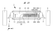
実施の形態7では、磁気パターン30は、粗調磁気パターン31および微調磁気パターン32とは別の磁気パターンであって、且つ、磁気センサ20用の異常検出用パターン31cを有する。
この異常検出用パターン31cは、粗調磁気パターン31と同様にN極の磁性体30NとS極の磁性体30Sとが交互に配置された構造を成す。しかし、X方向において、異常検出用パターン31cのN極の磁性体30NおよびS極の磁性体30Sの各々の長さは、粗調磁気パターン31のN極の磁性体30NおよびS極の磁性体30Sの各々の長さよりも短い。すなわち、異常検出用パターン31cのピッチは、粗調磁気パターン31のピッチよりも短い。
図20および図21に示されるように、実施の形態7では、異常検出用パターン31cが、粗調磁気パターン31の表面に形成されている。このような異常検出用パターン31cは、例えば、粗調磁気パターン31の表面の磁性を変化させることによって、形成することができる。
図22は、実施の形態7において磁気センサ20で検知される磁気信号の波形を示している。図22に示されている波形は、粗調磁気パターン31からの磁気信号の波形と、異常検出用パターン31cの磁気信号の波形とを重ね合わせた合成波形の一例であり、例えばセンサ出力信号Vsの波形と、異常検出用パターン31cの磁気信号の波形との合成波形である。ここでは、粗調磁気パターン31からの磁気信号の波形と、粗調磁気パターン31からの磁気信号の波形のピッチよりも短いピッチを有する凹凸型の波形とが重ね合わされている。言い換えれば、このような合成波形は、粗調磁気パターン31から発生し、且つ、長い波長を有する第1波形に、異常検出用パターン31cから発生し、且つ、第1波形よりも短い波長を有する第2波形が合成された波形である。
例えば、ある磁気センサ20が、このような合成波形の磁気信号のうち、ピッチの短い凹部および凸部の両方を検知した場合、この磁気センサ20は故障していないと判断される。実施の形態7では、このような合成波形の磁気信号を用いることで、ラック10の移動距離が非常に短く、粗調磁気パターン31からの磁気信号のみでは検知が難しかった場合でも、磁気センサ20の故障の検知を迅速に行うことができる。
また、実施の形態7では、異常検出用パターン31cが、粗調磁気パターン31の表面全体に形成されている例を示したが、異常検出用パターン31cは、粗調磁気パターン31の表面の一部に形成されていてもよい。また、異常検出用パターン31cは、微調磁気パターン32にも形成されていてもよい。また、異常検出用パターン31cは、粗調磁気パターン31および微調磁気パターン32と異なる領域に形成されていてもよい。例えば、粗調磁気パターン31と微調磁気パターン32との間の領域に、異常検出用パターン31cが独立して形成されていてもよい。
なお、実施の形態7で説明した技術に、実施の形態2~6で説明した技術を適宜組み合わせて適用することもできる。
以上、本発明を実施するための形態に基づき具体的に説明したが、本発明は上記実施の形態に限定されるものではなく、その要旨を逸脱しない範囲で種々変更可能である。
1 ステアリング装置
2 タイロッド
3 車輪
10 ラック
10a 平坦部
10b 曲部
10G ラック歯
11 ハウジング
12 ステアリングホイール
13 シャフト
20 磁気センサ
21 磁気モジュール
22 センサ基板
30 磁気パターン
30N N極の磁性体
30S S極の磁性体
31 粗調磁気パターン
31a 第1粗調磁気領域
31b 第2粗調磁気領域
31c 異常検出用パターン
32 微調磁気パターン
33 非磁性体膜
34 バーニア型磁気パターン
35 バーニア型磁気パターン
40 磁気パターンの中央および磁気モジュールの中央
41 非磁性体膜の中央
42 第2パターンの中央および磁気モジュールの中央
43 ラックの中央
44 ラック歯形成領域
45 ラック歯形成領域の中央
50 出力読取器
51 0/1判定器
52 第1レジスタ
53 XOR判定器
54 ラッチ判断器
55 第2レジスタ
56 出力読取器
57 ADC
60 固定ピン
CLKr クロック信号
Ts 判定開始信号
Te 判定終了信号
Vdig 0/1判定出力信号
Vr 読取出力信号
Vreg1_in 第1レジスタ入力信号
Vreg1_out 第1レジスタ出力信号
Vreg2_in 第2レジスタ入力信号
Vreg2_out 第2レジスタ出力信号
Vs センサ出力信号
Vxor XOR判定出力信号
Claims (15)
- ハウジングと、
前記ハウジングの内部に設けられ、且つ、第1方向に移動可能なラックと、
前記ラック上に形成され、且つ、複数のN極の磁性体および複数のS極の磁性体を有する磁気パターンと、
前記ハウジングに取り付けられ、且つ、前記磁気パターンからの磁気信号を検知するための磁気センサと、
を有する、ステアリング装置。 - 請求項1に記載のステアリング装置において、
前記ラックは、少なくとも平坦部を有し、
前記磁気パターンは、前記ラックの前記平坦部に形成されている、ステアリング装置。 - 請求項1に記載のステアリング装置において、
前記ラックと前記磁気パターンとの間に、非磁性体膜を更に有する、ステアリング装置。 - 請求項3に記載のステアリング装置において、
前記非磁性体膜の面積は、前記磁気パターンの面積よりも大きく、
平面視において、前記磁気パターンは、前記非磁性体膜に内包されている、ステアリング装置。 - 請求項3に記載のステアリング装置において、
前記非磁性体膜を貫通し、且つ、前記ラックの内部に到達する固定ピンを更に有する、ステアリング装置。 - 請求項3に記載のステアリング装置において、
前記磁気パターンは、前記磁気センサに対向する前記磁気パターンの表面が露出するように、前記非磁性体膜の内部に埋め込まれている、ステアリング装置。 - 請求項1に記載のステアリング装置において、
前記磁気センサが、少なくとも1つの前記N極の磁性体および少なくとも1つの前記S極の磁性体からの磁気信号を受信した後、前記磁気センサが0値および1値の両方を出力した場合、前記磁気センサは正常であると判定され、前記磁気センサが0値または1値の何れか一方のみを出力した場合、前記磁気センサは故障であると判定される、ステアリング装置。 - 請求項7に記載のステアリング装置において、
前記磁気パターンは、前記複数のN極の磁性体および前記複数のS極の磁性体がM系列のパターンを構成している第1パターンと、平面視で前記第1方向と直交する第2方向において前記第1パターンと隣接するように配置され、且つ、前記N極の磁性体および前記S極の磁性体が交互に配置されている第2パターンとを有する、ステアリング装置。 - 請求項8に記載のステアリング装置において、
前記第1パターンは、前記複数のN極の磁性体および前記複数のS極の磁性体がランダムに配置されている第1領域と、前記第1領域に接続され、且つ、前記N極の磁性体および前記S極の磁性体が交互に配置されている第2領域とを有し、
前記磁気センサが正常であるか故障であるかの判定は、前記第1領域の一対の前記N極の磁性体および前記S極の磁性体からの磁気信号によって行われる、ステアリング装置。 - 請求項9に記載のステアリング装置において、
前記ハウジングに取り付けられ、且つ、複数の前記磁気センサを含む磁気モジュールを更に有し、
前記ラックが初期位置に位置している場合、平面視において、前記第1領域の中央が、前記磁気モジュールの一部と重なっている、ステアリング装置。 - 請求項8に記載のステアリング装置において、
前記磁気パターンは、前記第1パターンおよび前記第2パターンとは異なり、且つ、前記N極の磁性体および前記S極の磁性体が交互に配置されている第3パターンを有し、
前記第1方向において、前記第3パターンにおける前記N極の磁性体および前記S極の磁性体の各々の長さは、前記第1パターンにおける前記N極の磁性体および前記S極の磁性体の各々の長さよりも短く、
前記磁気センサが正常であるか故障であるかの判定は、前記第1パターンからの磁気信号の波形と、前記第3パターンからの磁気信号の波形との合成波形によって行われる、ステアリング装置。 - 請求項7に記載のステアリング装置において、
前記磁気パターンは、前記N極の磁性体および前記S極の磁性体が交互に配置されている第4パターンおよび第5パターンを有し、
前記第4パターンは、平面視で前記第1方向と直交する第2方向において、前記第5パターンと隣接するように配置され、
前記第1方向において、前記第4パターンにおける前記N極の磁性体および前記S極の磁性体の各々の長さは、前記第5パターンにおける前記N極の磁性体および前記S極の磁性体の各々の長さよりも長い、ステアリング装置。 - 請求項1に記載のステアリング装置において、
前記ハウジングに取り付けられ、且つ、複数の前記磁気センサを含む磁気モジュールを更に有し、
前記ラックが初期位置に位置している場合、平面視において、前記磁気パターンの中央が、前記磁気モジュールの一部と重なっている、ステアリング装置。 - 請求項1に記載のステアリング装置において、
前記ハウジングに取り付けられ、且つ、複数の前記磁気センサを含む磁気モジュールを更に有し、
前記ラックが初期位置に位置している場合、平面視において、前記磁気パターンの一部および前記磁気モジュールの一部が、前記第1方向における前記ラックの中央と重なっている、ステアリング装置。 - 請求項1に記載のステアリング装置において、
前記ハウジングに取り付けられ、且つ、複数の前記磁気センサを含む磁気モジュールを更に有し、
前記ラックは、前記第1方向に沿って複数のラック歯が形成されたラック歯形成領域を有し、
前記ラックが初期位置に位置している場合、平面視において、前記磁気パターンの一部および前記磁気モジュールの一部が、前記第1方向における前記ラック歯形成領域の中央と重なっている、ステアリング装置。
Applications Claiming Priority (2)
| Application Number | Priority Date | Filing Date | Title |
|---|---|---|---|
| JP2018238612A JP2020100214A (ja) | 2018-12-20 | 2018-12-20 | ステアリング装置 |
| JP2018-238612 | 2018-12-20 |
Publications (1)
| Publication Number | Publication Date |
|---|---|
| WO2020129401A1 true WO2020129401A1 (ja) | 2020-06-25 |
Family
ID=71101126
Family Applications (1)
| Application Number | Title | Priority Date | Filing Date |
|---|---|---|---|
| PCT/JP2019/041749 Ceased WO2020129401A1 (ja) | 2018-12-20 | 2019-10-24 | ステアリング装置 |
Country Status (2)
| Country | Link |
|---|---|
| JP (1) | JP2020100214A (ja) |
| WO (1) | WO2020129401A1 (ja) |
Cited By (1)
| Publication number | Priority date | Publication date | Assignee | Title |
|---|---|---|---|---|
| DE102024208460A1 (de) | 2024-09-05 | 2026-03-05 | Robert Bosch Gesellschaft mit beschränkter Haftung | Lenkstange und Sensorsystem für ein Steer-by-Wire-Lenksystem |
Families Citing this family (1)
| Publication number | Priority date | Publication date | Assignee | Title |
|---|---|---|---|---|
| JP7845134B2 (ja) * | 2022-09-27 | 2026-04-14 | 株式会社プロテリアル | 位置検出装置及び車両用転舵装置 |
Citations (11)
| Publication number | Priority date | Publication date | Assignee | Title |
|---|---|---|---|---|
| JPS5764893A (en) * | 1980-10-08 | 1982-04-20 | Tokyo Optical | Encoder |
| JPS63177019A (ja) * | 1986-10-09 | 1988-07-21 | Alpine Electron Inc | 位置センサ |
| JPH04351914A (ja) * | 1991-05-30 | 1992-12-07 | Hitachi Metals Ltd | リニア磁気エンコーダ |
| JP2000352523A (ja) * | 1999-06-10 | 2000-12-19 | Harmonic Drive Syst Ind Co Ltd | アブソリュートセンサ |
| JP2001028095A (ja) * | 1998-03-17 | 2001-01-30 | Clarion Co Ltd | 道路交通システム |
| JP2004144667A (ja) * | 2002-10-25 | 2004-05-20 | Okuma Corp | 位置情報の異常検出装置 |
| JP2005164551A (ja) * | 2003-12-05 | 2005-06-23 | Seiko Epson Corp | 磁気式リニアアブソリュートエンコーダ |
| JP2006020415A (ja) * | 2004-07-01 | 2006-01-19 | Yamazaki Mazak Corp | リニアモータ用位置検出装置 |
| JP2015517108A (ja) * | 2012-04-20 | 2015-06-18 | ザ ティムケン カンパニー | インデックス信号を生成するための磁気エンコーダ |
| JP2017143206A (ja) * | 2016-02-12 | 2017-08-17 | Ntn株式会社 | 磁気リニアエンコーダの着磁装置および製造方法 |
| JP2017165327A (ja) * | 2016-03-17 | 2017-09-21 | 株式会社ジェイテクト | ステアリング装置 |
-
2018
- 2018-12-20 JP JP2018238612A patent/JP2020100214A/ja active Pending
-
2019
- 2019-10-24 WO PCT/JP2019/041749 patent/WO2020129401A1/ja not_active Ceased
Patent Citations (11)
| Publication number | Priority date | Publication date | Assignee | Title |
|---|---|---|---|---|
| JPS5764893A (en) * | 1980-10-08 | 1982-04-20 | Tokyo Optical | Encoder |
| JPS63177019A (ja) * | 1986-10-09 | 1988-07-21 | Alpine Electron Inc | 位置センサ |
| JPH04351914A (ja) * | 1991-05-30 | 1992-12-07 | Hitachi Metals Ltd | リニア磁気エンコーダ |
| JP2001028095A (ja) * | 1998-03-17 | 2001-01-30 | Clarion Co Ltd | 道路交通システム |
| JP2000352523A (ja) * | 1999-06-10 | 2000-12-19 | Harmonic Drive Syst Ind Co Ltd | アブソリュートセンサ |
| JP2004144667A (ja) * | 2002-10-25 | 2004-05-20 | Okuma Corp | 位置情報の異常検出装置 |
| JP2005164551A (ja) * | 2003-12-05 | 2005-06-23 | Seiko Epson Corp | 磁気式リニアアブソリュートエンコーダ |
| JP2006020415A (ja) * | 2004-07-01 | 2006-01-19 | Yamazaki Mazak Corp | リニアモータ用位置検出装置 |
| JP2015517108A (ja) * | 2012-04-20 | 2015-06-18 | ザ ティムケン カンパニー | インデックス信号を生成するための磁気エンコーダ |
| JP2017143206A (ja) * | 2016-02-12 | 2017-08-17 | Ntn株式会社 | 磁気リニアエンコーダの着磁装置および製造方法 |
| JP2017165327A (ja) * | 2016-03-17 | 2017-09-21 | 株式会社ジェイテクト | ステアリング装置 |
Cited By (1)
| Publication number | Priority date | Publication date | Assignee | Title |
|---|---|---|---|---|
| DE102024208460A1 (de) | 2024-09-05 | 2026-03-05 | Robert Bosch Gesellschaft mit beschränkter Haftung | Lenkstange und Sensorsystem für ein Steer-by-Wire-Lenksystem |
Also Published As
| Publication number | Publication date |
|---|---|
| JP2020100214A (ja) | 2020-07-02 |
Similar Documents
| Publication | Publication Date | Title |
|---|---|---|
| CN102472642B (zh) | 多周期绝对位置传感器 | |
| US20100301845A1 (en) | Absolute measurement steering angle sensor arrangement | |
| US12111220B2 (en) | Sensor assembly for sensing a steering torque and an absolute angular position, and sensor device having said sensor assembly | |
| CN110678714B (zh) | 磁传感器 | |
| CN102472768B (zh) | 车辆控制装置和其所采用的旋转检测装置 | |
| US6871554B2 (en) | Absolute angle sensor with a magnetic encoder having non-even spaced reference pulses | |
| US20150211890A1 (en) | Sensor Arrangement for Detecting Angles of Rotation on a Rotated Component | |
| KR20150135307A (ko) | 외부 자계에 민감하지 않은 홀 센서 | |
| US20170370747A1 (en) | Angle sensor and angle sensor system | |
| WO2017163967A1 (ja) | 回転検出装置 | |
| US12522286B2 (en) | Elongate body comprising a cursor band for a vehicle system of a vehicle | |
| CN118575058A (zh) | 磁传感器系统 | |
| JP2020100214A (ja) | ステアリング装置 | |
| CN110741230B (zh) | 位置传感器 | |
| JP6455314B2 (ja) | 回転検出装置 | |
| JP6798530B2 (ja) | リニアポジションセンサ | |
| KR20070073912A (ko) | 자동차의 스티어링 각을 결정하기 위한 방법 및 장치 | |
| JP5170457B2 (ja) | 角度検出装置 | |
| US20220113164A1 (en) | Sensor system, system and method for determining a position or a rotational angle | |
| Kapser et al. | GMR sensors in automotive applications | |
| WO2019171763A1 (ja) | リニアポジションセンサ | |
| WO2019167449A1 (ja) | リニアポジションセンサ | |
| JP5428625B2 (ja) | 回転角度検出装置 | |
| JP7545439B2 (ja) | 回転角度検出装置及び電気制御装置 | |
| KR20100001526A (ko) | 고정밀의 조향각도 검출장치 |
Legal Events
| Date | Code | Title | Description |
|---|---|---|---|
| 121 | Ep: the epo has been informed by wipo that ep was designated in this application |
Ref document number: 19901071 Country of ref document: EP Kind code of ref document: A1 |
|
| NENP | Non-entry into the national phase |
Ref country code: DE |
|
| 122 | Ep: pct application non-entry in european phase |
Ref document number: 19901071 Country of ref document: EP Kind code of ref document: A1 |