WO2020126468A1 - A household appliance comprising a decorative element which can be attached to/detached from the knob - Google Patents
A household appliance comprising a decorative element which can be attached to/detached from the knob Download PDFInfo
- Publication number
- WO2020126468A1 WO2020126468A1 PCT/EP2019/083455 EP2019083455W WO2020126468A1 WO 2020126468 A1 WO2020126468 A1 WO 2020126468A1 EP 2019083455 W EP2019083455 W EP 2019083455W WO 2020126468 A1 WO2020126468 A1 WO 2020126468A1
- Authority
- WO
- WIPO (PCT)
- Prior art keywords
- knob
- decorative element
- household appliance
- base
- wall
- Prior art date
- Legal status (The legal status is an assumption and is not a legal conclusion. Google has not performed a legal analysis and makes no representation as to the accuracy of the status listed.)
- Ceased
Links
Images



Classifications
-
- D—TEXTILES; PAPER
- D06—TREATMENT OF TEXTILES OR THE LIKE; LAUNDERING; FLEXIBLE MATERIALS NOT OTHERWISE PROVIDED FOR
- D06F—LAUNDERING, DRYING, IRONING, PRESSING OR FOLDING TEXTILE ARTICLES
- D06F34/00—Details of control systems for washing machines, washer-dryers or laundry dryers
- D06F34/28—Arrangements for programme selection, e.g. control panels therefor; Arrangements for indicating programme parameters, e.g. the selected programme or its progress
- D06F34/30—Arrangements for programme selection, e.g. control panels therefor; Arrangements for indicating programme parameters, e.g. the selected programme or its progress characterised by mechanical features, e.g. buttons or rotary dials
-
- A—HUMAN NECESSITIES
- A47—FURNITURE; DOMESTIC ARTICLES OR APPLIANCES; COFFEE MILLS; SPICE MILLS; SUCTION CLEANERS IN GENERAL
- A47L—DOMESTIC WASHING OR CLEANING; SUCTION CLEANERS IN GENERAL
- A47L15/00—Washing or rinsing machines for crockery or tableware
- A47L15/42—Details
- A47L15/4293—Arrangements for programme selection, e.g. control panels; Indication of the selected programme, programme progress or other parameters of the programme, e.g. by using display panels
-
- G—PHYSICS
- G05—CONTROLLING; REGULATING
- G05G—CONTROL DEVICES OR SYSTEMS INSOFAR AS CHARACTERISED BY MECHANICAL FEATURES ONLY
- G05G1/00—Controlling members, e.g. knobs or handles; Assemblies or arrangements thereof; Indicating position of controlling members
- G05G1/08—Controlling members for hand actuation by rotary movement, e.g. hand wheels
- G05G1/10—Details, e.g. of discs, knobs, wheels or handles
-
- F—MECHANICAL ENGINEERING; LIGHTING; HEATING; WEAPONS; BLASTING
- F24—HEATING; RANGES; VENTILATING
- F24C—DOMESTIC STOVES OR RANGES ; DETAILS OF DOMESTIC STOVES OR RANGES, OF GENERAL APPLICATION
- F24C7/00—Stoves or ranges heated by electric energy
- F24C7/08—Arrangement or mounting of control or safety devices
- F24C7/082—Arrangement or mounting of control or safety devices on ranges, e.g. control panels, illumination
Definitions
- Household appliances for example cooking devices, dishwashers and in particular washers/dryers, comprise a panel, a control unit and one or more than one knob which enable the functions thereof to be monitored and controlled by the user.
- the knobs are directly attached to the shafts which are mechanically connected to the switches on the control unit behind the panel by means of the housings on the panel or by means of an intermediate piece from the front of the panel.
- the shafts which are connected to the knobs also move and the functions at predetermined positions depending on the user preferences, for example functions like in which program the laundries should be washed, at which rpm the spin-drying should be performed or at which temperature the wash water should be used, are enabled to be selected.
- the function of the knob group in the system is to rotate the encoder component provided on the panel, thus enabling the functions at predetermined positions depending on the user preferences, for example functions like in which program the laundries should be washed in a washing machine, at which rpm the spin-drying should be performed or at which temperature the wash water should be used, to be selected.
- the state of the art program knobs are produced in multiple pieces according to developing designs, changing customer perception and demands. Increased number of components and changing component shapes result in the emergence of different solutions for interconnecting these components. Multi-piece program knobs are preferred since said knobs allow the use of different materials and colors.
- the components of the program knob are mounted to each other by means of conventional simple claw structures.
- the claw structure in order to stretch the claw structure, long claws and seating surfaces whereon said claws are positioned are required.
- decorative elements should be detachable.
- the aim of the present invention is the realization of a household appliance comprising a decorative element which is detachably fixed to the knob.
- the household appliance realized in order to attain the aim of the present invention, explicated in the first claim and the respective claims thereof comprises a knob and a decorative element which are disposed one within the other and which lock and fix onto each other when rotated relative to each other.
- the "poke-yoke gap" provided on the knob and the “poke-yoke rib” provided on the decorative element align with each other, thus preventing improper mounting process.
- the inner components of the program knob can be mounted to each other by using a narrower space by means of the protrusions in the radial direction.
- small components can be mounted by means of ribbed structures which can operate in the radial direction, the need for long claws is eliminated, the claw seating surface on the mounted component is prevented from remaining behind the component seating surface in order to align with the long claw structure.
- the appearance of the knob is enabled to be easily changed according to the customer demands by mounting the decorative element, which can be easily attached/detached when desired, onto the knob. Moreover, since the decorative element and the knob are fixed to each other in a safe manner, the risk of the detachment of the decorative element and the knob from each other under load is eliminated.
- Figure 1 - is the general front view of the panel of a household appliance.
- Figure 2 - is the rear view of the knob and the decorative element.
- Figure 4 - is the perspective view of the knob and the decorative element.
- Figure 5 — is the exploded view of the knob and the decorative element.
- Figure 8 - is the perspective view of the knob and the decorative element while being mounted to each other.
- Figure 10 - is the perspective view, at a different position, of the knob and the decorative element while being mounted to each other.
- Figure 12 - is the perspective view, at the last position, of the knob and the decorative element while being mounted to each other.
- the household appliance (1) comprises a panel (2) which enables the user to monitor and control the functions of the appliance (1); a control unit which is disposed behind the panel (2); a shaft which is connected to the control unit and which enables user preferences to be transmitted to the control unit; a knob (3) which actuates the shaft; a decorative element piece (4) which is disposed between the knob (3) and the shaft, which is nested with the knob (3) and which is borne in the knob (3); an opening (7) which is provided on the knob (3) and which receives the decorative element (4); and
- the knob (3) and the decorative element (4) are concentrically mounted to each other in a male-female connection.
- the decorative element (4) is fitted into the knob (3) so as to be borne.
- the decorative element (4) can be fitted into the knob (3) only in a single manner. Otherwise, the decorative element (4) cannot be properly seated into the knob (3).
- the knob (3) bears against the decorative element (4).
- the decorative element (4) and the knob (3) are rotated relative to each other and by means of the locking mechanism (5) disposed on the decorative element (4) and the knob (3), the decorative element (4) is prevented from moving in the overlapping axes of the knob (3) and the decorative element (4) and in the radial direction, thus the knob (3) and the decorative element (4) are mounted to each other.
- knob (3) and the decorative element (4) are desired to be detached from each other, with a force applied from the outside the locking mechanism (5) is triggered and first the knob (3) and the decorative element (4) are enabled to move relative to each other in the radial direction and then the knob (3) and the decorative element (4) are rotated relative to each other and the decorative element (4) is enabled to be detached from over the knob (3) ( Figure 3, Figure 4 and Figure 5).
- the knob (3) has preferably a cylindrical structure, and comprises a base (8) and a first wall (9) which extends over said base (8) and which circumferentially surrounds the base (8) ( Figure 6).
- the decorative element (4) has a structure suitable for the knob (3), preferably a cylindrical structure, and comprises a ceiling (10), a second wall (11) which extends from the ceiling (10), which circumferentially surrounds the ceiling (10) and which is surrounded by the first wall (9) when the decorative element (4) is mounted onto the knob (3), and a bearing (12) which is disposed on the ceiling (10) and which extends from the center of the ceiling (10) towards the base (8) ( Figure 7).
- the locking mechanism (5) comprises at least two recesses (13) which are symmetrically provided on the base (8) and at least two protrusions (14) which are symmetrically provided at the wall of the bearing (12) and which are seated into the recesses (13) when the mounting of the decorative element (4) to the knob (3) is completed.
- the guiding mechanism (6) comprises a housing (15) which is provided on the base (8) of the knob (3) and a claw (16) which is provided at the wall of the bearing (12) on the decorative element (4) and which is seated into the housing (15) so as to enable the decorative element (4) and the knob (3) to be aligned with each other, thus ensuring the mounting process can be performed only in a single manner.
- the risk of improperly mounting the knob (3) and the decorative element (4) to each other is eliminated.
- the household appliance (1) comprises at least one barrier (17) which is provided at the side of the recess (13) and which, with the impact of the side of the protrusion (14), prevents the knob (3) and the decorative element (4) from moving relative to each other in the radial direction and thus which enables the knob (3) and the decorative element (4) to be properly mounted to each other.
- the household appliance (1) comprises at least one mounting claw (18) which is provided at the wall of the bearing (12), which has an inclination allowing the bearing (12) to pass through the opening (7) on the base (8), and which is made flexible by forming cut-outs (20) therearound.
- the knob (3) and the decorative element (4) are concentrically disposed one within the other.
- the first wall (9) completely surrounds the second wall (11), and the locking mechanism (5) passes through the recess (13) and reaches the other side of the base (8) ( Figure 8 and Figure 9).
- the mounting claw (18) is stretched by the base (8); and the decorative element (4) is enabled to be fitted into the knob (3) in the vertical direction.
- the mounting claw (18) After passing through the opening (7), the mounting claw (18) returns to its initial position, thus enabling the decorative element (4) to be mounted onto the knob (3) in the vertical direction.
- the household appliance (1) comprises an additional protrusion (19) which is provided on the wall of the bearing (12) parallel to the protrusion (14) and which is positioned at a certain distance from the protrusion (14).
- the panel (2) is placed between the additional protrusion (19) and the protrusion (14), thus enabling the door (3) to be mounted onto the panel (2).
Landscapes
- Engineering & Computer Science (AREA)
- Textile Engineering (AREA)
- Physics & Mathematics (AREA)
- General Physics & Mathematics (AREA)
- Automation & Control Theory (AREA)
- Mechanical Control Devices (AREA)
Abstract
The present invention relates to a household appliance (1) comprising a panel (2) which enables the user to monitor and control the functions of the appliance (1); a control unit which is disposed behind the panel (2); a shaft which is connected to the control unit and which enables user preferences to be transmitted to the control unit; a knob (3) which actuates the shaft; a decorative element piece (4) which is disposed between the knob (3) and the shaft, which is nested with the knob (3) and which is borne in the knob (3); an opening (7) which is provided on the knob (3) and which receives the decorative element (4).
Description
The present invention relates to a household appliance comprising a decorative element which can be easily attached to/detached from the knob.
Household appliances, for example cooking devices, dishwashers and in particular washers/dryers, comprise a panel, a control unit and one or more than one knob which enable the functions thereof to be monitored and controlled by the user. The knobs are directly attached to the shafts which are mechanically connected to the switches on the control unit behind the panel by means of the housings on the panel or by means of an intermediate piece from the front of the panel. As the knobs are moved, the shafts which are connected to the knobs also move and the functions at predetermined positions depending on the user preferences, for example functions like in which program the laundries should be washed, at which rpm the spin-drying should be performed or at which temperature the wash water should be used, are enabled to be selected. The function of the knob group in the system is to rotate the encoder component provided on the panel, thus enabling the functions at predetermined positions depending on the user preferences, for example functions like in which program the laundries should be washed in a washing machine, at which rpm the spin-drying should be performed or at which temperature the wash water should be used, to be selected.
The state of the art program knobs are produced in multiple pieces according to developing designs, changing customer perception and demands. Increased number of components and changing component shapes result in the emergence of different solutions for interconnecting these components. Multi-piece program knobs are preferred since said knobs allow the use of different materials and colors.
In the state of the art, the components of the program knob are mounted to each other by means of conventional simple claw structures. In these embodiments, in order to stretch the claw structure, long claws and seating surfaces whereon said claws are positioned are required. Moreover, at a program knob changing according to customer demands, decorative elements should be detachable.
In the state of the art European Patent Application No. EP1829071, a household appliance is disclosed, comprising a knob mounted to the panel.
In the state of the art British Patent Application No. GB2040396, a control knob is disclosed, which is fixed to the shaft in a safe manner.
The aim of the present invention is the realization of a household appliance comprising a decorative element which is detachably fixed to the knob.
The household appliance realized in order to attain the aim of the present invention, explicated in the first claim and the respective claims thereof comprises a knob and a decorative element which are disposed one within the other and which lock and fix onto each other when rotated relative to each other.
In the present invention, the household appliance mainly comprises the knob and the decorative element. The flexible mounting claw provided on the decorative element is fitted onto the knob in the vertical direction by changing the decorative element to the mounting position. By means of the form of the flexible mounting claw, the mounting claw stretches backwards, thus allowing mounting in the vertical direction. Afterwards, the decorative element is rotated counterclockwise until the edge of the protrusion hits the barrier. As a result of this process, the flexible mounting claw returns to its initial position and the flexible mounting claw hits the claw and limits the same clockwise. The mounting of the decorative element, which is fixed in both directions, to the knob is thus completed.
In an embodiment of the present invention, in order to prevent the decorative element from being mounted wrong, the "poke-yoke gap" provided on the knob and the "poke-yoke rib" provided on the decorative element align with each other, thus preventing improper mounting process.
By means of the present invention, the inner components of the program knob can be mounted to each other by using a narrower space by means of the protrusions in the radial direction. Thus, small components can be mounted by means of ribbed structures which can operate in the radial direction, the need for long claws is eliminated, the claw seating surface on the mounted component is prevented from remaining behind the component seating surface in order to align with the long claw structure.
By means of the present invention, the appearance of the knob is enabled to be easily changed according to the customer demands by mounting the decorative element, which can be easily attached/detached when desired, onto the knob. Moreover, since the decorative element and the knob are fixed to each other in a safe manner, the risk of the detachment of the decorative element and the knob from each other under load is eliminated.
The knob and the decorative element are concentrically mounted to each other in a male-female connection. The decorative element is fitted into the knob and the side walls of the decorative element bear against the base of the knob. In this case, the decorative element and the knob are rotated relative to each other, and the protrusions enter into the recesses disposed oppositely thereto and the decorative element is prevented from moving over the knob in the vertical direction. The barrier prevents movement in the radial direction. Thus, by means of the locking mechanism and the guiding mechanism, the knob and the decorative element are prevented from moving relative to each other both in the vertical direction and the radial direction and are fixed by interlocking.
A household appliance realized in order to attain the aim of the present invention is illustrated in the attached figures, where:
Figure 1 - is the general front view of the panel of a household appliance.
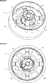
Figure 2 - is the rear view of the knob and the decorative element.
Figure 3 - is the view of the cross section A-A in Figure 2.
Figure 4 - is the perspective view of the knob and the decorative element.
Figure 5 – is the exploded view of the knob and the decorative element.
Figure 6 - is the view of the knob.
Figure 7 – is the assembled view of the knob and the decorative element.
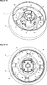
Figure 8 - is the perspective view of the knob and the decorative element while being mounted to each other.
Figure 9 - is the top view of the knob and the decorative element while being mounted to each other.
Figure 10 - is the perspective view, at a different position, of the knob and the decorative element while being mounted to each other.
Figure 11 - is the top view, at a different position, of the knob and the decorative element while being mounted to each other.
Figure 12 - is the perspective view, at the last position, of the knob and the decorative element while being mounted to each other.
Figure 13 - is the top view, at the last position, of the knob and the decorative element while being mounted to each other.
The elements illustrated in the figures are numbered as follows:
- Household appliance
- Panel
- Knob
- Decorative element
- Locking mechanism
- Guiding mechanism
- Opening
- Base
- First wall
- Ceiling
- Second wall
- Bearing
- Recess
- Protrusion
- Housing
- Claw
- Barrier
- Mounting claw
- Additional protrusion
- Cut-out
The household appliance (1) comprises a panel (2) which enables the user to monitor and control the functions of the appliance (1); a control unit which is disposed behind the panel (2); a shaft which is connected to the control unit and which enables user preferences to be transmitted to the control unit; a knob (3) which actuates the shaft; a decorative element piece (4) which is disposed between the knob (3) and the shaft, which is nested with the knob (3) and which is borne in the knob (3); an opening (7) which is provided on the knob (3) and which receives the decorative element (4); and
- a locking mechanism (5) which enables the decorative element (4) to be fixed to the knob (3) in the vertical axis direction and in the radial direction when rotated with respect to each other; and
- a guiding mechanism (6) which enables the knob (3) and the decorative element (4) seated into the opening (7) to align with each other, thus ensuring that the mounting process can be performed in a single manner (Figure 1, Figure 2).
The knob (3) and the decorative element (4) are concentrically mounted to each other in a male-female connection. The decorative element (4) is fitted into the knob (3) so as to be borne. However, during this process, by means of the guiding mechanism (6) provided on the knob (3) and the opening (7), the decorative element (4) can be fitted into the knob (3) only in a single manner. Otherwise, the decorative element (4) cannot be properly seated into the knob (3). When the decorative element (4) is properly seated into the knob (3), the knob (3) bears against the decorative element (4). In this case, the decorative element (4) and the knob (3) are rotated relative to each other and by means of the locking mechanism (5) disposed on the decorative element (4) and the knob (3), the decorative element (4) is prevented from moving in the overlapping axes of the knob (3) and the decorative element (4) and in the radial direction, thus the knob (3) and the decorative element (4) are mounted to each other. When the knob (3) and the decorative element (4) are desired to be detached from each other, with a force applied from the outside the locking mechanism (5) is triggered and first the knob (3) and the decorative element (4) are enabled to move relative to each other in the radial direction and then the knob (3) and the decorative element (4) are rotated relative to each other and the decorative element (4) is enabled to be detached from over the knob (3) (Figure 3, Figure 4 and Figure 5).
The knob (3) has preferably a cylindrical structure, and comprises a base (8) and a first wall (9) which extends over said base (8) and which circumferentially surrounds the base (8) (Figure 6).
The decorative element (4) has a structure suitable for the knob (3), preferably a cylindrical structure, and comprises a ceiling (10), a second wall (11) which extends from the ceiling (10), which circumferentially surrounds the ceiling (10) and which is surrounded by the first wall (9) when the decorative element (4) is mounted onto the knob (3), and a bearing (12) which is disposed on the ceiling (10) and which extends from the center of the ceiling (10) towards the base (8) (Figure 7).
The locking mechanism (5) comprises at least two recesses (13) which are symmetrically provided on the base (8) and at least two protrusions (14) which are symmetrically provided at the wall of the bearing (12) and which are seated into the recesses (13) when the mounting of the decorative element (4) to the knob (3) is completed.
The guiding mechanism (6) comprises a housing (15) which is provided on the base (8) of the knob (3) and a claw (16) which is provided at the wall of the bearing (12) on the decorative element (4) and which is seated into the housing (15) so as to enable the decorative element (4) and the knob (3) to be aligned with each other, thus ensuring the mounting process can be performed only in a single manner. By means of the guiding mechanism (6), the risk of improperly mounting the knob (3) and the decorative element (4) to each other is eliminated.
In an embodiment of the present invention, the household appliance (1) comprises at least one barrier (17) which is provided at the side of the recess (13) and which, with the impact of the side of the protrusion (14), prevents the knob (3) and the decorative element (4) from moving relative to each other in the radial direction and thus which enables the knob (3) and the decorative element (4) to be properly mounted to each other.
In another embodiment of the present invention, the household appliance (1) comprises at least one mounting claw (18) which is provided at the wall of the bearing (12), which has an inclination allowing the bearing (12) to pass through the opening (7) on the base (8), and which is made flexible by forming cut-outs (20) therearound.
In an embodiment of the present invention, a plurality of cut-outs (20) are provided on the base (8). Thus, saving in material is provided.
By properly aligning the housing (15) and the claw (16) of the guiding mechanism (6), the knob (3) and the decorative element (4) are concentrically disposed one within the other. In this case, the first wall (9) completely surrounds the second wall (11), and the locking mechanism (5) passes through the recess (13) and reaches the other side of the base (8) (Figure 8 and Figure 9). At the same time, the mounting claw (18) is stretched by the base (8); and the decorative element (4) is enabled to be fitted into the knob (3) in the vertical direction. After passing through the opening (7), the mounting claw (18) returns to its initial position, thus enabling the decorative element (4) to be mounted onto the knob (3) in the vertical direction. When the decorative element (4) and the knob (3) are rotated around the bearing (12) relative to each other less than a full tour, the protrusion (14) passing over the other side of the base (8) moves away from the level of the recess (13) and bears against the base (8) (Figure 10 and Figure 11). The rotation process continues until the edge of the protrusion (14) bears against the barrier (17). When the protrusion (14) bears against the barrier (17), the mounting of the knob (3) to the decorative element (4) is completed (Figure 12 and Figure 13).
In an embodiment of the present invention, the household appliance (1) comprises an additional protrusion (19) which is provided on the wall of the bearing (12) parallel to the protrusion (14) and which is positioned at a certain distance from the protrusion (14). The panel (2) is placed between the additional protrusion (19) and the protrusion (14), thus enabling the door (3) to be mounted onto the panel (2).
By means of the present invention, the visual quality of the knob (3) is improved by means of the decorative element (4). Since the mounting process requires a narrower space, the design limitations are decreased. Consequently, a larger design capacity is obtained.
Claims (8)
- A household appliance (1) comprising a panel (2) which enables the user to monitor and control the functions of the appliance (1); a control unit which is disposed behind the panel (2); a shaft which is connected to the control unit and which enables user preferences to be transmitted to the control unit; a knob (3) which actuates the shaft; a decorative element piece (4) which is disposed between the knob (3) and the shaft, which is nested with the knob (3) and which is borne in the knob (3); an opening (7) which is provided on the knob (3) and which receives the decorative element (4); characterized by- a locking mechanism (5) which enables the decorative element (4) to be fixed to the knob (3) in the vertical axis direction and in the radial direction when rotated with respect to each other; and- a guiding mechanism (6) which enables the knob (3) and the decorative element (4) seated into the opening (7) to align with each other, thus ensuring that the mounting process can be performed in a single manner.
- A household appliance (1) as in Claim 1, characterized by the knob (3) comprising a base (8) and a first wall (9) which extends over said base (8) and which circumferentially surrounds the base (8).
- A household appliance (1) as in Claim 1 and 2, characterized by the decorative element (4) having a structure suitable for the knob (3) and comprising a ceiling (10), a second wall (11) which extends from the ceiling (10), which circumferentially surrounds the ceiling (10) and which is surrounded by the first wall (9) when the decorative element (4) is mounted onto the knob (3), and a bearing (12) which is disposed on the ceiling (10) and which extends from the center of the ceiling (10) towards the base (8).
- A household appliance (1) as in Claim 1, characterized by the locking mechanism (5) comprising at least two recesses (13) which are symmetrically provided on the base (8) and at least two protrusions (14) which are symmetrically provided at the wall of the bearing (12) and which are seated into the recesses (13) when the mounting of the decorative element (4) to the knob (3) is completed.
- A household appliance (1) as in Claim 1, characterized by the guiding mechanism (6) comprising a housing (15) which is provided on the base (8) of the knob (3) and a claw (16) which is provided at the wall of the bearing (12) on the decorative element (4) and which is seated into the housing (15) so as to enable the decorative element (4) and the knob (3) to be aligned with each other, thus ensuring the mounting process can be performed only in a single manner.
- A household appliance (1) as in Claim 1, 4, characterized by at least one barrier (17) which is provided at the side of the recess (13) and which, with the impact of the side of the protrusion (14), prevents the knob (3) and the decorative element (4) from moving relative to each other in the radial direction and thus which enables the knob (3) and the decorative element (4) to be properly mounted to each other.
- A household appliance (1) as in Claim 1, 3, characterized by at least one mounting claw (18) which is provided at the wall of the bearing (12), which has an inclination allowing the bearing (12) to pass through the opening (7) on the base (8), and which is made flexible by forming cut-outs (20) therearound.
- A household appliance (1) as in Claim 1, 4, characterized by an additional protrusion (19) which is provided on the wall of the bearing (12) parallel to the protrusion (14) and which is positioned at a certain distance from the protrusion (14).
Applications Claiming Priority (2)
| Application Number | Priority Date | Filing Date | Title |
|---|---|---|---|
| TR2018/19857 | 2018-12-19 | ||
| TR201819857 | 2018-12-19 |
Publications (1)
| Publication Number | Publication Date |
|---|---|
| WO2020126468A1 true WO2020126468A1 (en) | 2020-06-25 |
Family
ID=68806747
Family Applications (1)
| Application Number | Title | Priority Date | Filing Date |
|---|---|---|---|
| PCT/EP2019/083455 Ceased WO2020126468A1 (en) | 2018-12-19 | 2019-12-03 | A household appliance comprising a decorative element which can be attached to/detached from the knob |
Country Status (1)
| Country | Link |
|---|---|
| WO (1) | WO2020126468A1 (en) |
Citations (7)
| Publication number | Priority date | Publication date | Assignee | Title |
|---|---|---|---|---|
| GB2040396A (en) | 1979-01-26 | 1980-08-28 | Breter Spa | Securing a control knob to a shaft |
| EP1829071A1 (en) | 2004-12-24 | 2007-09-05 | Arçelik Anonim Sirketi | A household appliance |
| WO2017026963A1 (en) * | 2015-08-10 | 2017-02-16 | Arcelik Anonim Sirketi | A household appliance comprising a knob mounted to the control panel |
| WO2017044059A1 (en) * | 2015-09-08 | 2017-03-16 | Arcelik Anonim Sirketi | A household appliance comprising a decorative element that can be attached to/detached from the knob |
| WO2017134222A1 (en) * | 2016-02-05 | 2017-08-10 | Arcelik Anonim Sirketi | A household appliance comprising a transparent knob |
| WO2017152945A1 (en) * | 2016-03-08 | 2017-09-14 | Arcelik Anonim Sirketi | Rotary knob with improved structural integrity |
| WO2017194500A2 (en) * | 2016-05-09 | 2017-11-16 | Arcelik Anonim Sirketi | A household appliance comprising a knob safely mounted onto the panel |
-
2019
- 2019-12-03 WO PCT/EP2019/083455 patent/WO2020126468A1/en not_active Ceased
Patent Citations (7)
| Publication number | Priority date | Publication date | Assignee | Title |
|---|---|---|---|---|
| GB2040396A (en) | 1979-01-26 | 1980-08-28 | Breter Spa | Securing a control knob to a shaft |
| EP1829071A1 (en) | 2004-12-24 | 2007-09-05 | Arçelik Anonim Sirketi | A household appliance |
| WO2017026963A1 (en) * | 2015-08-10 | 2017-02-16 | Arcelik Anonim Sirketi | A household appliance comprising a knob mounted to the control panel |
| WO2017044059A1 (en) * | 2015-09-08 | 2017-03-16 | Arcelik Anonim Sirketi | A household appliance comprising a decorative element that can be attached to/detached from the knob |
| WO2017134222A1 (en) * | 2016-02-05 | 2017-08-10 | Arcelik Anonim Sirketi | A household appliance comprising a transparent knob |
| WO2017152945A1 (en) * | 2016-03-08 | 2017-09-14 | Arcelik Anonim Sirketi | Rotary knob with improved structural integrity |
| WO2017194500A2 (en) * | 2016-05-09 | 2017-11-16 | Arcelik Anonim Sirketi | A household appliance comprising a knob safely mounted onto the panel |
Similar Documents
| Publication | Publication Date | Title |
|---|---|---|
| EP2602377B1 (en) | Washing machine having a knob assembly | |
| EP3516103B1 (en) | A household appliance comprising a knob | |
| EP2458060B1 (en) | Control-panel assembly for household appliances and household appliance provided with such control-panel assembly | |
| US8438878B2 (en) | Control unit of laundry processing apparatus | |
| EP2140058B1 (en) | Laundry treating apparatus | |
| KR20160084073A (en) | Laundry treating apparatus and door assembly thereof | |
| US8179697B2 (en) | Control panel assembly and washing machine having the same | |
| CN110578234B (en) | Drum washing machine and its control panel | |
| US6422047B1 (en) | Washing machine with unbalance detection and control system | |
| WO2013098243A2 (en) | A household appliance | |
| WO2017044059A1 (en) | A household appliance comprising a decorative element that can be attached to/detached from the knob | |
| EP2764524B1 (en) | Household appliance with turn knob | |
| EP3447182B1 (en) | Household appliance and method for operating a household appliance | |
| EP4187009B1 (en) | A household appliance comprising a knob | |
| WO2017194500A2 (en) | A household appliance comprising a knob safely mounted onto the panel | |
| WO2017134222A1 (en) | A household appliance comprising a transparent knob | |
| US20130175149A1 (en) | Button spring | |
| EP3334320B1 (en) | A household appliance comprising a knob mounted to the control panel | |
| EP3139394B1 (en) | A household appliance comprising a knob safely mounted onto the panel | |
| EP4202104B1 (en) | A washing machine | |
| EP3347517B1 (en) | Household appliance wherein liquid leakage into the control unit is prevented | |
| WO2017194539A1 (en) | A household appliance comprising a knob mounted to the control panel | |
| TR2021007885A1 (en) | A ROTARY KNOB ASSEMBLY FOR HOME APPLIANCES | |
| KR20070067463A (en) | Control panel assembly of washing machine | |
| KR20070028151A (en) | Control panel of drum washing machine and upper decoration |
Legal Events
| Date | Code | Title | Description |
|---|---|---|---|
| 121 | Ep: the epo has been informed by wipo that ep was designated in this application |
Ref document number: 19816271 Country of ref document: EP Kind code of ref document: A1 |
|
| NENP | Non-entry into the national phase |
Ref country code: DE |
|
| 122 | Ep: pct application non-entry in european phase |
Ref document number: 19816271 Country of ref document: EP Kind code of ref document: A1 |