EP3347517B1 - Household appliance wherein liquid leakage into the control unit is prevented - Google Patents
Household appliance wherein liquid leakage into the control unit is prevented Download PDFInfo
- Publication number
- EP3347517B1 EP3347517B1 EP16760573.2A EP16760573A EP3347517B1 EP 3347517 B1 EP3347517 B1 EP 3347517B1 EP 16760573 A EP16760573 A EP 16760573A EP 3347517 B1 EP3347517 B1 EP 3347517B1
- Authority
- EP
- European Patent Office
- Prior art keywords
- panel
- knob
- control unit
- shaft
- household appliance
- Prior art date
- Legal status (The legal status is an assumption and is not a legal conclusion. Google has not performed a legal analysis and makes no representation as to the accuracy of the status listed.)
- Active
Links
- 239000007788 liquid Substances 0.000 title description 15
- 210000000078 claw Anatomy 0.000 description 20
- 230000004888 barrier function Effects 0.000 description 6
- XLYOFNOQVPJJNP-UHFFFAOYSA-N water Substances O XLYOFNOQVPJJNP-UHFFFAOYSA-N 0.000 description 3
- 239000003599 detergent Substances 0.000 description 2
- 238000010411 cooking Methods 0.000 description 1
- 238000001035 drying Methods 0.000 description 1
- 238000004519 manufacturing process Methods 0.000 description 1
- 238000010297 mechanical methods and process Methods 0.000 description 1
- 230000002093 peripheral effect Effects 0.000 description 1
Images
Classifications
-
- D—TEXTILES; PAPER
- D06—TREATMENT OF TEXTILES OR THE LIKE; LAUNDERING; FLEXIBLE MATERIALS NOT OTHERWISE PROVIDED FOR
- D06F—LAUNDERING, DRYING, IRONING, PRESSING OR FOLDING TEXTILE ARTICLES
- D06F34/00—Details of control systems for washing machines, washer-dryers or laundry dryers
- D06F34/28—Arrangements for program selection, e.g. control panels therefor; Arrangements for indicating program parameters, e.g. the selected program or its progress
- D06F34/34—Arrangements for program selection, e.g. control panels therefor; Arrangements for indicating program parameters, e.g. the selected program or its progress characterised by mounting or attachment features, e.g. detachable control panels or detachable display panels
-
- D—TEXTILES; PAPER
- D06—TREATMENT OF TEXTILES OR THE LIKE; LAUNDERING; FLEXIBLE MATERIALS NOT OTHERWISE PROVIDED FOR
- D06F—LAUNDERING, DRYING, IRONING, PRESSING OR FOLDING TEXTILE ARTICLES
- D06F34/00—Details of control systems for washing machines, washer-dryers or laundry dryers
- D06F34/28—Arrangements for program selection, e.g. control panels therefor; Arrangements for indicating program parameters, e.g. the selected program or its progress
- D06F34/30—Arrangements for program selection, e.g. control panels therefor; Arrangements for indicating program parameters, e.g. the selected program or its progress characterised by mechanical features, e.g. buttons or rotary dials
Definitions
- the present invention relates to a household appliance comprising a knob that wherein the liquid spilled from the panel onto the region where the control unit is located is eliminated.
- Household appliances for example cooking devices, dishwashers and washers/dryers, comprise a panel, a control unit and one or more than one knob that enable the functions thereof to be monitored and controlled by the user.
- the knobs are directly attached to the shafts that are mechanically fastened to the switches on the control unit behind the panel by means of the housings on the panel or by means of an intermediate piece from the front of the panel.
- the shafts that are connected to the knobs also move and the functions at predetermined positions depending on the user preferences, for example functions like in which program the laundries should be washed, at which rpm the spin-drying should be performed or at which temperature the wash water should be used, are enabled to be selected.
- the knobs are mounted on the shaft that is connected to the control unit behind the panel from the front side of the panel for ease of production.
- the knob is mounted on the panel by means of clawed structures, some tolerances are needed to be taken into consideration in order that the shaft and the knob can be easily borne to each other. Therefore, a gap should be left around the clawed structures. While facilitating the rotation of the knobs, these gaps decrease the strength of the knob against impacts from outside, furthermore in the case liquid, especially water, liquid detergent etc. is spilled on the household appliance from the region the knob is mounted on the panel, the liquid leaks around the knob and reaches the control unit and cause important unfavorable situations.
- a household appliance that comprises a knob mounted to the panel.
- WO 2006/067764 A1 discloses a household appliance comprising a panel enabling the user to monitor and control the functions of the household appliance, a control unit disposed behind the panel, a shaft that is connected to the control unit and that enables user preferences to be transmitted to the control unit, a knob that actuates the shaft, a housing that is disposed on the panel and wherein the knob is placed, a guiding member having a flange that is mounted on the shaft that has a diameter larger than the diameter of the housing and that remains behind the panel and a sheath that extends on the flange and that surrounds the shaft.
- the aim of the present invention is the realization of a household appliance comprising a knob wherein liquids spilled from outside such as water, detergent etc. is enabled to be moved away before reaching the control unit.
- the household appliance realized in order to attain the aim of the present invention, explicated in the first claim and the respective claims thereof, comprises a flange that is mounted to the shaft mechanically connected to the control unit from behind the panel and a guiding member that extends on the said flange and that has a sheath surrounding the shaft.
- the liquid trickling over the panel and leaking from inside the housing to behind the panel is prevented from passing to the control unit. Furthermore, in the case the knob is dislodged for any reason, direct access to the control unit is prevented.
- the flange has a circular configuration and the guiding member comprises a wall that surrounds the flange all around.
- the sheath is fitted on the shaft snap-fittingly and the shaft is enabled to be borne to the guiding member.
- An intermediate piece is fitted over the sheath and the guiding member that is mounted on the shaft snap-fittingly is enabled to be mounted on the intermediate piece.
- the liquid that may leak from the front of the panel through the housing where the knob is mounted is enabled to be held and moved away by the flange before reaching the control unit. Moreover, in the case the knob is dislodged due to any load, direct access to the control unit is prevented by means of the guiding member by the flange completely closing the housing from behind the panel.
- the household appliance (1) for example the laundry washer/dryer, comprises a panel (2) enabling the user to monitor and control the functions of the household appliance (1), a control unit (3) disposed behind the panel (2), a shaft (4) that is connected to the control unit (3) and that enables user preferences to be transmitted to the control unit (3), a knob (5) that actuates the shaft (4), a housing (14) that is disposed on the panel (2) and wherein the knob (5) is placed, and a guiding member (22) having
- the guiding member (22) is mounted freely on the shaft (3) situated on the control unit (3). While the control unit (3) is mounted on the panel (2), the guiding member (22) is fitted over the knob (5) and provides the connection between the knob (5) and the shaft (4).
- the flange (23) preferably has a circular configuration and is surrounded by a wall (25).
- the said wall (25) surrounding the flange (23) bears against the rear side of the panel (2).
- the surface of the flange (23) and the panel (2) are parallel to one another ( Figure 3 ).
- the sheath (24) has a configuration matching that of the shaft (4) and preferably has a stepped structure.
- the sheath (24) is fitted over the shaft (4) snap-fittingly and the shaft (4) is borne in the guiding member (22) ( Figure 4 ).
- the household appliance (1) comprises an intermediate piece (7) disposed between the guiding member (22) and the knob (5).
- the intermediate piece (7) comprises a base (9), a body (8) that extends on the base (9) and surrounds the guiding member (22), a bearing (12) that is disposed in the body (8) and wherein the sheath (24) and hence the guiding member (22) enter and are supported, and at least two claws (10) having a fixed end (20) that is disposed on the body (8), that is fixed to the body (8) and that first passes from the housing (14) while being mounted and a free end (21) that stretches while passing through the housing (14) by getting close to the body (8), that resumes its initial position after passing through the housing (14) and that compresses the panel (2) between itself and the base (9) by bearing against the panel (2).
- the knob (5) is mounted to the household appliance (1) in the following manner.
- the intermediate piece (7) is inserted into the housing (14) from behind the panel (2) and the intermediate piece (7) is moved inside the housing (14) until the base (9) bears against the rear wall of the panel (2).
- the free ends (21) of the claws (10) stretch and get close towards the body (8).
- the free ends (21) this time stretch in the reverse direction and move away from the body (8), resume their initial positions and bear against the front side of the panel (2).
- the panel (2) is squeezed between the claws (10) and the base (9) and the intermediate piece (7) is fixed on the panel (2) so as to move only in a radial direction.
- the shaft (4) and the guiding member (22) mounted thereon are seated in the bearing (12) and the panel (2) with the intermediate piece (7) thereon is fixed on the household appliance (1).
- the knob (5) is mounted on the part of the body (8) that passes through the housing (14) to the front side of the panel (2) and the assembly of the knob (5) on the intermediate piece (7), hence on the panel (2) of the household appliance (1) is completed.
- the guiding member (22) liquid leakages that may occur from the housing (14) towards the control unit (3) are prevented and the liquid leaking from the housing (14) is prevented from reaching the control unit (3) by the flange (3) and is enabled to be moved away from the control unit (3).
- the intermediate piece (7) is preferably a cylindrical element and comprises at least two guides (16) that extend on the inner surface of the bearing (12) along the axis of the bearing (12) and that prevent the intermediate piece (7) from moving relative to the shaft (4) and the guiding member (22), and a peripheral barrier (15) that forms the ceiling of the body (8).
- the base (9) on the intermediate piece (7) corresponds to the region between the claws (10) on the body (8) and therefore two bases (9) are situated between two opposite claws (10).
- the knob (5) comprises a handle (6) that enables the user to actuate the knob (5) by holding, a second bearing (13) that surrounds the intermediate piece (7) and at least two auxiliary claws (11) with one end fixed on the second bearing (13) and the other end being free.
- the auxiliary claws (11) are formed by cutting out the surface of the second bearing (13). While the knob (5) is mounted on the intermediate piece (7), the auxiliary claw (11) corresponds to the claws (10) on the intermediate piece (7).
- the intermediate piece (7) While the knob (5) is being mounted on the intermediate piece (7) fixed secured on the panel (2), the intermediate piece (7) is moved forward in the second bearing (13) and the two auxiliary claws (11) stretch and move on the claws (10) to bear against the barrier (15) and the knob (5) can no longer move forward. Since the portions of the auxiliary claws (11) fixed on the second bearing (13) bear against the claws (10) on the intermediate piece (7), this prevents the said claws (10) from moving and stretching outwards further. In this case, the assembly of the knob (5) on the intermediate piece (7) and hence on the panel (2) is completed.
- the panel (2) comprises a circular groove (19) that surrounds the housing (14) all around and a circular protrusion (17) disposed on the said groove (19).
- the free end (21) of the claw (10) of the intermediate piece (7) bearing against the panel (2) is seated on the said protrusion (17).
- the household appliance (1) comprises a decorative element (18) mounted on the knob (5).
- the decorative element (18) can be produced as a single piece with the knob (5) or can be produced separately. In the case being produced separately, the decorative element (18) is mounted on the knob (5) by using various mechanical methods.
Description
- The present invention relates to a household appliance comprising a knob that wherein the liquid spilled from the panel onto the region where the control unit is located is eliminated.
- Household appliances, for example cooking devices, dishwashers and washers/dryers, comprise a panel, a control unit and one or more than one knob that enable the functions thereof to be monitored and controlled by the user. The knobs are directly attached to the shafts that are mechanically fastened to the switches on the control unit behind the panel by means of the housings on the panel or by means of an intermediate piece from the front of the panel. As the knobs are moved, the shafts that are connected to the knobs also move and the functions at predetermined positions depending on the user preferences, for example functions like in which program the laundries should be washed, at which rpm the spin-drying should be performed or at which temperature the wash water should be used, are enabled to be selected.
- In the state of the art, the knobs are mounted on the shaft that is connected to the control unit behind the panel from the front side of the panel for ease of production. In this state of the art embodiment, while the knob is mounted on the panel by means of clawed structures, some tolerances are needed to be taken into consideration in order that the shaft and the knob can be easily borne to each other. Therefore, a gap should be left around the clawed structures. While facilitating the rotation of the knobs, these gaps decrease the strength of the knob against impacts from outside, furthermore in the case liquid, especially water, liquid detergent etc. is spilled on the household appliance from the region the knob is mounted on the panel, the liquid leaks around the knob and reaches the control unit and cause important unfavorable situations. In the case liquid is spilled on the household appliance and the liquid leaks around the knob and reaches the control unit, short circuit may occur and this can result in unrecoverable damages. Therefore, liquid entering to the region of the control unit should be prevented or the leaked liquid should be directed away from the region where the control unit is located.
- In the state of the art European Patent Application No.
EP1829071 , a household appliance is disclosed, that comprises a knob mounted to the panel. - In the state of the art British Patent Application No.
GB2040396 - Further, document
WO 2006/067764 A1 discloses a household appliance comprising a panel enabling the user to monitor and control the functions of the household appliance, a control unit disposed behind the panel, a shaft that is connected to the control unit and that enables user preferences to be transmitted to the control unit, a knob that actuates the shaft, a housing that is disposed on the panel and wherein the knob is placed, a guiding member having a flange that is mounted on the shaft that has a diameter larger than the diameter of the housing and that remains behind the panel and a sheath that extends on the flange and that surrounds the shaft. - Document
WO 2015/180851 A1 discloses an extension that is integrated with the light barrier disposed between the front panel and the printed circuit board and that partially covers the switch. When liquid leaks into the household appliance from around the knob, it drops onto the extension that remains in front of the panel. - The aim of the present invention is the realization of a household appliance comprising a knob wherein liquids spilled from outside such as water, detergent etc. is enabled to be moved away before reaching the control unit.
- The household appliance realized in order to attain the aim of the present invention, explicated in the first claim and the respective claims thereof, comprises a flange that is mounted to the shaft mechanically connected to the control unit from behind the panel and a guiding member that extends on the said flange and that has a sheath surrounding the shaft.
- By means of the present invention, the liquid trickling over the panel and leaking from inside the housing to behind the panel is prevented from passing to the control unit. Furthermore, in the case the knob is dislodged for any reason, direct access to the control unit is prevented.
- The flange has a circular configuration and the guiding member comprises a wall that surrounds the flange all around.
- The sheath is fitted on the shaft snap-fittingly and the shaft is enabled to be borne to the guiding member.
- An intermediate piece is fitted over the sheath and the guiding member that is mounted on the shaft snap-fittingly is enabled to be mounted on the intermediate piece.
- By means of the present invention, the liquid that may leak from the front of the panel through the housing where the knob is mounted, is enabled to be held and moved away by the flange before reaching the control unit. Moreover, in the case the knob is dislodged due to any load, direct access to the control unit is prevented by means of the guiding member by the flange completely closing the housing from behind the panel.
- A household appliance realized in order to attain the aim of the present invention is illustrated in the attached figures, where:
-
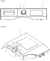
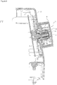
Figure 1 - is the general front view of the panel of a household appliance. -
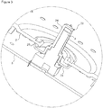
Figure 2 - is the cross-sectional perspective view of the panel, the control unit, the guiding member and the shaft. -
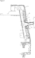
Figure 3 - is the view of detail A inFigure 2 . -
Figure 4 - is the cross-sectional view of the control unit, the shaft and the guiding member that are fixed on the panel. -
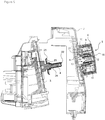
Figure 5 - is the exploded cross-sectional view of the panel, the control unit, the shaft and the guiding member when the intermediate piece and the knob are fixed on the panel. -
Figure 6 - is the cross-sectional view of the guiding member, the intermediate piece, the shaft, the control unit and the knob that are fixed on the panel. - The elements illustrated in the figures are numbered as follows:
- 1.
- Household appliance
- 2.
- Panel
- 3.
- Control unit
- 4.
- Shaft
- 5.
- Knob
- 6.
- Handle
- 7.
- Intermediate piece
- 8.
- Body
- 9.
- Base
- 10.
- Claw
- 11.
- Auxiliary claw
- 12.
- Bearing
- 13.
- Second bearing
- 14.
- Housing
- 15.
- Barrier
- 16.
- Guide
- 17.
- Protrusion
- 18.
- Decorative element
- 19.
- Groove
- 20.
- Fixed end
- 21.
- Free end
- 22.
- Guiding member
- 23.
- Flange
- 24.
- Sheath
- 25.
- Wall
- The household appliance (1), for example the laundry washer/dryer, comprises a panel (2) enabling the user to monitor and control the functions of the household appliance (1), a control unit (3) disposed behind the panel (2), a shaft (4) that is connected to the control unit (3) and that enables user preferences to be transmitted to the control unit (3), a knob (5) that actuates the shaft (4), a housing (14) that is disposed on the panel (2) and wherein the knob (5) is placed, and a guiding member (22) having
- a flange (23) that is mounted on the shaft (4), that has a diameter larger than the diameter of the housing (14) and that remains behind the panel (2), and
- a sheath (24) that extends on the flange (23) and that surrounds the shaft (4) (
Figure 1, Figure 2 ). - The guiding member (22) is mounted freely on the shaft (3) situated on the control unit (3). While the control unit (3) is mounted on the panel (2), the guiding member (22) is fitted over the knob (5) and provides the connection between the knob (5) and the shaft (4).
- The flange (23) preferably has a circular configuration and is surrounded by a wall (25). When the assembly of the knob (5) to the panel (2) is completed, the said wall (25) surrounding the flange (23) bears against the rear side of the panel (2). When the assembly operation is completed, the surface of the flange (23) and the panel (2) are parallel to one another (
Figure 3 ). - The sheath (24) has a configuration matching that of the shaft (4) and preferably has a stepped structure. The sheath (24) is fitted over the shaft (4) snap-fittingly and the shaft (4) is borne in the guiding member (22) (
Figure 4 ). - In the preferred embodiment of the present invention, the household appliance (1) comprises an intermediate piece (7) disposed between the guiding member (22) and the knob (5). The intermediate piece (7) comprises a base (9), a body (8) that extends on the base (9) and surrounds the guiding member (22), a bearing (12) that is disposed in the body (8) and wherein the sheath (24) and hence the guiding member (22) enter and are supported, and at least two claws (10) having a fixed end (20) that is disposed on the body (8), that is fixed to the body (8) and that first passes from the housing (14) while being mounted and a free end (21) that stretches while passing through the housing (14) by getting close to the body (8), that resumes its initial position after passing through the housing (14) and that compresses the panel (2) between itself and the base (9) by bearing against the panel (2).
- The knob (5) is mounted to the household appliance (1) in the following manner. First, the intermediate piece (7) is inserted into the housing (14) from behind the panel (2) and the intermediate piece (7) is moved inside the housing (14) until the base (9) bears against the rear wall of the panel (2). Meanwhile, the free ends (21) of the claws (10) stretch and get close towards the body (8). When the claws (10) go past the housing (14), the free ends (21) this time stretch in the reverse direction and move away from the body (8), resume their initial positions and bear against the front side of the panel (2). In this situation, the panel (2) is squeezed between the claws (10) and the base (9) and the intermediate piece (7) is fixed on the panel (2) so as to move only in a radial direction. Afterwards, the shaft (4) and the guiding member (22) mounted thereon are seated in the bearing (12) and the panel (2) with the intermediate piece (7) thereon is fixed on the household appliance (1). The knob (5) is mounted on the part of the body (8) that passes through the housing (14) to the front side of the panel (2) and the assembly of the knob (5) on the intermediate piece (7), hence on the panel (2) of the household appliance (1) is completed. By means of the guiding member (22), liquid leakages that may occur from the housing (14) towards the control unit (3) are prevented and the liquid leaking from the housing (14) is prevented from reaching the control unit (3) by the flange (3) and is enabled to be moved away from the control unit (3). Furthermore, by means of the guiding member (22), direct access from outside to the control unit (3) is prevented in case the knob (5) is dislodged due to any reason. In the case the knob (5) is dislodged, direct access to the control unit (3) from the front side of the panel (2) through the housing (14) is prevented by means of the flange (23) that completely covers the housing (14) from the rear side of the panel (2) (
Figure 5 andFigure 6 ). - The intermediate piece (7) is preferably a cylindrical element and comprises at least two guides (16) that extend on the inner surface of the bearing (12) along the axis of the bearing (12) and that prevent the intermediate piece (7) from moving relative to the shaft (4) and the guiding member (22), and a peripheral barrier (15) that forms the ceiling of the body (8). The base (9) on the intermediate piece (7) corresponds to the region between the claws (10) on the body (8) and therefore two bases (9) are situated between two opposite claws (10).
- The knob (5) comprises a handle (6) that enables the user to actuate the knob (5) by holding, a second bearing (13) that surrounds the intermediate piece (7) and at least two auxiliary claws (11) with one end fixed on the second bearing (13) and the other end being free. The auxiliary claws (11) are formed by cutting out the surface of the second bearing (13). While the knob (5) is mounted on the intermediate piece (7), the auxiliary claw (11) corresponds to the claws (10) on the intermediate piece (7). While the knob (5) is being mounted on the intermediate piece (7) fixed secured on the panel (2), the intermediate piece (7) is moved forward in the second bearing (13) and the two auxiliary claws (11) stretch and move on the claws (10) to bear against the barrier (15) and the knob (5) can no longer move forward. Since the portions of the auxiliary claws (11) fixed on the second bearing (13) bear against the claws (10) on the intermediate piece (7), this prevents the said claws (10) from moving and stretching outwards further. In this case, the assembly of the knob (5) on the intermediate piece (7) and hence on the panel (2) is completed. Forces that are exerted from the outside in the same direction as the axis of the shaft (4) try to separate the claws (10) from the barrier (15) but the claws (10) stretch towards each other due to the said force and bear against the barrier (15) in a safer manner. Therefore, the knob (5) is prevented from separating from the panel (2) also as a result of the tensile force exerted on the knob (5).
- The panel (2) comprises a circular groove (19) that surrounds the housing (14) all around and a circular protrusion (17) disposed on the said groove (19). In the preferred embodiment of the present invention, the free end (21) of the claw (10) of the intermediate piece (7) bearing against the panel (2) is seated on the said protrusion (17).
- In an embodiment of the present invention, the household appliance (1) comprises a decorative element (18) mounted on the knob (5). The decorative element (18) can be produced as a single piece with the knob (5) or can be produced separately. In the case being produced separately, the decorative element (18) is mounted on the knob (5) by using various mechanical methods.
Claims (4)
- A household appliance (1) comprising a panel (2) enabling the user to monitor and control the functions of the household appliance (1), a control unit (3) disposed behind the panel (2), a shaft (4) that is connected to the control unit (3) and that enables user preferences to be transmitted to the control unit (3), a knob (5) that actuates the shaft (4), a housing (14) that is disposed on the panel (2) and wherein the knob (5) is placed, a guiding member (22) having• a circular flange (23) that is mounted on the shaft (4), that has a diameter larger than the diameter of the housing (14) and that remains behind the panel (2) and• a sheath (24) that extends on the flange (23) and that surrounds the shaft (4) characterized by• the guiding member (22) comprising the flange (23) that is surrounded by a wall (25) and• the wall (25) that bears against the rear side of the panel (2) when the assembly of the knob (5) to the panel (2) is completed.
- A household appliance (1) as in any one of the above claims, characterized by the panel (2) that is parallel to the surface of the flange (23).
- A household appliance (1) as in Claim 1, characterized by the sheath (24) having a stepped configuration.
- A household appliance (1) as in any one of the above claims, characterized by the sheath (24) that is mounted on the shaft (4) snap-fittingly.
Applications Claiming Priority (2)
| Application Number | Priority Date | Filing Date | Title |
|---|---|---|---|
| TR201511133 | 2015-09-08 | ||
| PCT/TR2016/050269 WO2017044058A1 (en) | 2015-09-08 | 2016-08-05 | Household appliance wherein liquid leakage into the control unit is prevented |
Publications (2)
| Publication Number | Publication Date |
|---|---|
| EP3347517A1 EP3347517A1 (en) | 2018-07-18 |
| EP3347517B1 true EP3347517B1 (en) | 2019-11-06 |
Family
ID=56855784
Family Applications (1)
| Application Number | Title | Priority Date | Filing Date |
|---|---|---|---|
| EP16760573.2A Active EP3347517B1 (en) | 2015-09-08 | 2016-08-05 | Household appliance wherein liquid leakage into the control unit is prevented |
Country Status (2)
| Country | Link |
|---|---|
| EP (1) | EP3347517B1 (en) |
| WO (1) | WO2017044058A1 (en) |
Family Cites Families (4)
| Publication number | Priority date | Publication date | Assignee | Title |
|---|---|---|---|---|
| IT7920629V0 (en) | 1979-01-26 | 1979-01-26 | Breter Spa | PLUG-IN KNOB, PARTICULARLY FOR ELECTRICAL EQUIPMENT. |
| DE3823813C2 (en) * | 1988-07-14 | 1996-12-05 | Miele & Cie | Control device for a household appliance |
| ATE498189T1 (en) * | 2004-12-24 | 2011-02-15 | Arcelik As | HOUSEHOLD APPLIANCE |
| EP3149236A1 (en) * | 2014-05-29 | 2017-04-05 | Arçelik Anonim Sirketi | A household appliance comprising a front panel |
-
2016
- 2016-08-05 EP EP16760573.2A patent/EP3347517B1/en active Active
- 2016-08-05 WO PCT/TR2016/050269 patent/WO2017044058A1/en active Application Filing
Non-Patent Citations (1)
| Title |
|---|
| None * |
Also Published As
| Publication number | Publication date |
|---|---|
| EP3347517A1 (en) | 2018-07-18 |
| WO2017044058A1 (en) | 2017-03-16 |
Similar Documents
| Publication | Publication Date | Title |
|---|---|---|
| CA2527758C (en) | Appliance with membrane overlay | |
| CN107771229B (en) | Washing machine | |
| US20100043499A1 (en) | Control unit of laundry processing apparatus | |
| EP3516103B1 (en) | A household appliance comprising a knob | |
| KR20160084073A (en) | Laundry treating apparatus and door assembly thereof | |
| KR20130065374A (en) | Knob assembly and washing machine having the same | |
| US9777421B2 (en) | Control panel and clothes treating apparatus having the same | |
| EP3347517B1 (en) | Household appliance wherein liquid leakage into the control unit is prevented | |
| RU2413043C2 (en) | Washing or washing/drying machine with barrier device | |
| WO2017044059A1 (en) | A household appliance comprising a decorative element that can be attached to/detached from the knob | |
| EP3139394B1 (en) | A household appliance comprising a knob safely mounted onto the panel | |
| CA2432242C (en) | Membrane switch venting arrangement for washing appliance | |
| WO2016101971A1 (en) | A waterproof control panel assembly for an electrical household appliance | |
| TR201703225A2 (en) | ||
| EP3334320B1 (en) | A household appliance comprising a knob mounted to the control panel | |
| EP2764524B1 (en) | Household appliance with turn knob | |
| CN107849788B (en) | Drum type washing machine | |
| WO2017134222A1 (en) | A household appliance comprising a transparent knob | |
| WO2017194500A2 (en) | A household appliance comprising a knob safely mounted onto the panel | |
| WO2015180851A1 (en) | A household appliance comprising a front panel | |
| EP2787112B1 (en) | Control method of a control panel of a clothes treating apparatus | |
| KR20160084074A (en) | Laundry treating apparatus | |
| US9443670B2 (en) | Contamination resistant push button switch | |
| WO2013182931A3 (en) | Electrical household appliance with motor fixing system | |
| WO2018103951A1 (en) | A dishwasher comprising a card holder |
Legal Events
| Date | Code | Title | Description |
|---|---|---|---|
| STAA | Information on the status of an ep patent application or granted ep patent |
Free format text: STATUS: THE INTERNATIONAL PUBLICATION HAS BEEN MADE |
|
| PUAI | Public reference made under article 153(3) epc to a published international application that has entered the european phase |
Free format text: ORIGINAL CODE: 0009012 |
|
| STAA | Information on the status of an ep patent application or granted ep patent |
Free format text: STATUS: REQUEST FOR EXAMINATION WAS MADE |
|
| 17P | Request for examination filed |
Effective date: 20180228 |
|
| AK | Designated contracting states |
Kind code of ref document: A1 Designated state(s): AL AT BE BG CH CY CZ DE DK EE ES FI FR GB GR HR HU IE IS IT LI LT LU LV MC MK MT NL NO PL PT RO RS SE SI SK SM TR |
|
| AX | Request for extension of the european patent |
Extension state: BA ME |
|
| DAV | Request for validation of the european patent (deleted) | ||
| DAX | Request for extension of the european patent (deleted) | ||
| RAP1 | Party data changed (applicant data changed or rights of an application transferred) |
Owner name: ARCELIK ANONIM SIRKETI |
|
| GRAP | Despatch of communication of intention to grant a patent |
Free format text: ORIGINAL CODE: EPIDOSNIGR1 |
|
| STAA | Information on the status of an ep patent application or granted ep patent |
Free format text: STATUS: GRANT OF PATENT IS INTENDED |
|
| INTG | Intention to grant announced |
Effective date: 20190729 |
|
| GRAS | Grant fee paid |
Free format text: ORIGINAL CODE: EPIDOSNIGR3 |
|
| GRAA | (expected) grant |
Free format text: ORIGINAL CODE: 0009210 |
|
| STAA | Information on the status of an ep patent application or granted ep patent |
Free format text: STATUS: THE PATENT HAS BEEN GRANTED |
|
| AK | Designated contracting states |
Kind code of ref document: B1 Designated state(s): AL AT BE BG CH CY CZ DE DK EE ES FI FR GB GR HR HU IE IS IT LI LT LU LV MC MK MT NL NO PL PT RO RS SE SI SK SM TR |
|
| REG | Reference to a national code |
Ref country code: GB Ref legal event code: FG4D |
|
| REG | Reference to a national code |
Ref country code: CH Ref legal event code: EP Ref country code: AT Ref legal event code: REF Ref document number: 1198858 Country of ref document: AT Kind code of ref document: T Effective date: 20191115 |
|
| REG | Reference to a national code |
Ref country code: IE Ref legal event code: FG4D |
|
| REG | Reference to a national code |
Ref country code: DE Ref legal event code: R096 Ref document number: 602016023851 Country of ref document: DE |
|
| REG | Reference to a national code |
Ref country code: NL Ref legal event code: MP Effective date: 20191106 |
|
| REG | Reference to a national code |
Ref country code: LT Ref legal event code: MG4D |
|
| PG25 | Lapsed in a contracting state [announced via postgrant information from national office to epo] |
Ref country code: LV Free format text: LAPSE BECAUSE OF FAILURE TO SUBMIT A TRANSLATION OF THE DESCRIPTION OR TO PAY THE FEE WITHIN THE PRESCRIBED TIME-LIMIT Effective date: 20191106 Ref country code: PT Free format text: LAPSE BECAUSE OF FAILURE TO SUBMIT A TRANSLATION OF THE DESCRIPTION OR TO PAY THE FEE WITHIN THE PRESCRIBED TIME-LIMIT Effective date: 20200306 Ref country code: PL Free format text: LAPSE BECAUSE OF FAILURE TO SUBMIT A TRANSLATION OF THE DESCRIPTION OR TO PAY THE FEE WITHIN THE PRESCRIBED TIME-LIMIT Effective date: 20191106 Ref country code: LT Free format text: LAPSE BECAUSE OF FAILURE TO SUBMIT A TRANSLATION OF THE DESCRIPTION OR TO PAY THE FEE WITHIN THE PRESCRIBED TIME-LIMIT Effective date: 20191106 Ref country code: NL Free format text: LAPSE BECAUSE OF FAILURE TO SUBMIT A TRANSLATION OF THE DESCRIPTION OR TO PAY THE FEE WITHIN THE PRESCRIBED TIME-LIMIT Effective date: 20191106 Ref country code: FI Free format text: LAPSE BECAUSE OF FAILURE TO SUBMIT A TRANSLATION OF THE DESCRIPTION OR TO PAY THE FEE WITHIN THE PRESCRIBED TIME-LIMIT Effective date: 20191106 Ref country code: NO Free format text: LAPSE BECAUSE OF FAILURE TO SUBMIT A TRANSLATION OF THE DESCRIPTION OR TO PAY THE FEE WITHIN THE PRESCRIBED TIME-LIMIT Effective date: 20200206 Ref country code: GR Free format text: LAPSE BECAUSE OF FAILURE TO SUBMIT A TRANSLATION OF THE DESCRIPTION OR TO PAY THE FEE WITHIN THE PRESCRIBED TIME-LIMIT Effective date: 20200207 Ref country code: BG Free format text: LAPSE BECAUSE OF FAILURE TO SUBMIT A TRANSLATION OF THE DESCRIPTION OR TO PAY THE FEE WITHIN THE PRESCRIBED TIME-LIMIT Effective date: 20200206 Ref country code: SE Free format text: LAPSE BECAUSE OF FAILURE TO SUBMIT A TRANSLATION OF THE DESCRIPTION OR TO PAY THE FEE WITHIN THE PRESCRIBED TIME-LIMIT Effective date: 20191106 |
|
| PG25 | Lapsed in a contracting state [announced via postgrant information from national office to epo] |
Ref country code: HR Free format text: LAPSE BECAUSE OF FAILURE TO SUBMIT A TRANSLATION OF THE DESCRIPTION OR TO PAY THE FEE WITHIN THE PRESCRIBED TIME-LIMIT Effective date: 20191106 Ref country code: RS Free format text: LAPSE BECAUSE OF FAILURE TO SUBMIT A TRANSLATION OF THE DESCRIPTION OR TO PAY THE FEE WITHIN THE PRESCRIBED TIME-LIMIT Effective date: 20191106 Ref country code: IS Free format text: LAPSE BECAUSE OF FAILURE TO SUBMIT A TRANSLATION OF THE DESCRIPTION OR TO PAY THE FEE WITHIN THE PRESCRIBED TIME-LIMIT Effective date: 20200306 |
|
| PG25 | Lapsed in a contracting state [announced via postgrant information from national office to epo] |
Ref country code: AL Free format text: LAPSE BECAUSE OF FAILURE TO SUBMIT A TRANSLATION OF THE DESCRIPTION OR TO PAY THE FEE WITHIN THE PRESCRIBED TIME-LIMIT Effective date: 20191106 |
|
| PG25 | Lapsed in a contracting state [announced via postgrant information from national office to epo] |
Ref country code: RO Free format text: LAPSE BECAUSE OF FAILURE TO SUBMIT A TRANSLATION OF THE DESCRIPTION OR TO PAY THE FEE WITHIN THE PRESCRIBED TIME-LIMIT Effective date: 20191106 Ref country code: CZ Free format text: LAPSE BECAUSE OF FAILURE TO SUBMIT A TRANSLATION OF THE DESCRIPTION OR TO PAY THE FEE WITHIN THE PRESCRIBED TIME-LIMIT Effective date: 20191106 Ref country code: ES Free format text: LAPSE BECAUSE OF FAILURE TO SUBMIT A TRANSLATION OF THE DESCRIPTION OR TO PAY THE FEE WITHIN THE PRESCRIBED TIME-LIMIT Effective date: 20191106 Ref country code: DK Free format text: LAPSE BECAUSE OF FAILURE TO SUBMIT A TRANSLATION OF THE DESCRIPTION OR TO PAY THE FEE WITHIN THE PRESCRIBED TIME-LIMIT Effective date: 20191106 Ref country code: EE Free format text: LAPSE BECAUSE OF FAILURE TO SUBMIT A TRANSLATION OF THE DESCRIPTION OR TO PAY THE FEE WITHIN THE PRESCRIBED TIME-LIMIT Effective date: 20191106 |
|
| REG | Reference to a national code |
Ref country code: DE Ref legal event code: R097 Ref document number: 602016023851 Country of ref document: DE |
|
| REG | Reference to a national code |
Ref country code: AT Ref legal event code: MK05 Ref document number: 1198858 Country of ref document: AT Kind code of ref document: T Effective date: 20191106 |
|
| PG25 | Lapsed in a contracting state [announced via postgrant information from national office to epo] |
Ref country code: SK Free format text: LAPSE BECAUSE OF FAILURE TO SUBMIT A TRANSLATION OF THE DESCRIPTION OR TO PAY THE FEE WITHIN THE PRESCRIBED TIME-LIMIT Effective date: 20191106 Ref country code: SM Free format text: LAPSE BECAUSE OF FAILURE TO SUBMIT A TRANSLATION OF THE DESCRIPTION OR TO PAY THE FEE WITHIN THE PRESCRIBED TIME-LIMIT Effective date: 20191106 |
|
| PLBE | No opposition filed within time limit |
Free format text: ORIGINAL CODE: 0009261 |
|
| STAA | Information on the status of an ep patent application or granted ep patent |
Free format text: STATUS: NO OPPOSITION FILED WITHIN TIME LIMIT |
|
| 26N | No opposition filed |
Effective date: 20200807 |
|
| PG25 | Lapsed in a contracting state [announced via postgrant information from national office to epo] |
Ref country code: SI Free format text: LAPSE BECAUSE OF FAILURE TO SUBMIT A TRANSLATION OF THE DESCRIPTION OR TO PAY THE FEE WITHIN THE PRESCRIBED TIME-LIMIT Effective date: 20191106 Ref country code: AT Free format text: LAPSE BECAUSE OF FAILURE TO SUBMIT A TRANSLATION OF THE DESCRIPTION OR TO PAY THE FEE WITHIN THE PRESCRIBED TIME-LIMIT Effective date: 20191106 |
|
| PG25 | Lapsed in a contracting state [announced via postgrant information from national office to epo] |
Ref country code: IT Free format text: LAPSE BECAUSE OF FAILURE TO SUBMIT A TRANSLATION OF THE DESCRIPTION OR TO PAY THE FEE WITHIN THE PRESCRIBED TIME-LIMIT Effective date: 20191106 |
|
| PG25 | Lapsed in a contracting state [announced via postgrant information from national office to epo] |
Ref country code: MC Free format text: LAPSE BECAUSE OF FAILURE TO SUBMIT A TRANSLATION OF THE DESCRIPTION OR TO PAY THE FEE WITHIN THE PRESCRIBED TIME-LIMIT Effective date: 20191106 |
|
| REG | Reference to a national code |
Ref country code: CH Ref legal event code: PL |
|
| GBPC | Gb: european patent ceased through non-payment of renewal fee |
Effective date: 20200805 |
|
| PG25 | Lapsed in a contracting state [announced via postgrant information from national office to epo] |
Ref country code: LI Free format text: LAPSE BECAUSE OF NON-PAYMENT OF DUE FEES Effective date: 20200831 Ref country code: LU Free format text: LAPSE BECAUSE OF NON-PAYMENT OF DUE FEES Effective date: 20200805 Ref country code: CH Free format text: LAPSE BECAUSE OF NON-PAYMENT OF DUE FEES Effective date: 20200831 |
|
| REG | Reference to a national code |
Ref country code: BE Ref legal event code: MM Effective date: 20200831 |
|
| PG25 | Lapsed in a contracting state [announced via postgrant information from national office to epo] |
Ref country code: FR Free format text: LAPSE BECAUSE OF NON-PAYMENT OF DUE FEES Effective date: 20200831 |
|
| PG25 | Lapsed in a contracting state [announced via postgrant information from national office to epo] |
Ref country code: BE Free format text: LAPSE BECAUSE OF NON-PAYMENT OF DUE FEES Effective date: 20200831 Ref country code: GB Free format text: LAPSE BECAUSE OF NON-PAYMENT OF DUE FEES Effective date: 20200805 Ref country code: IE Free format text: LAPSE BECAUSE OF NON-PAYMENT OF DUE FEES Effective date: 20200805 |
|
| PG25 | Lapsed in a contracting state [announced via postgrant information from national office to epo] |
Ref country code: MT Free format text: LAPSE BECAUSE OF FAILURE TO SUBMIT A TRANSLATION OF THE DESCRIPTION OR TO PAY THE FEE WITHIN THE PRESCRIBED TIME-LIMIT Effective date: 20191106 Ref country code: CY Free format text: LAPSE BECAUSE OF FAILURE TO SUBMIT A TRANSLATION OF THE DESCRIPTION OR TO PAY THE FEE WITHIN THE PRESCRIBED TIME-LIMIT Effective date: 20191106 |
|
| PG25 | Lapsed in a contracting state [announced via postgrant information from national office to epo] |
Ref country code: MK Free format text: LAPSE BECAUSE OF FAILURE TO SUBMIT A TRANSLATION OF THE DESCRIPTION OR TO PAY THE FEE WITHIN THE PRESCRIBED TIME-LIMIT Effective date: 20191106 |
|
| PGFP | Annual fee paid to national office [announced via postgrant information from national office to epo] |
Ref country code: TR Payment date: 20230725 Year of fee payment: 8 |
|
| PGFP | Annual fee paid to national office [announced via postgrant information from national office to epo] |
Ref country code: DE Payment date: 20230821 Year of fee payment: 8 |