WO2020122015A1 - 無菌充填機チャンバー内の殺菌方法 - Google Patents
無菌充填機チャンバー内の殺菌方法 Download PDFInfo
- Publication number
- WO2020122015A1 WO2020122015A1 PCT/JP2019/048082 JP2019048082W WO2020122015A1 WO 2020122015 A1 WO2020122015 A1 WO 2020122015A1 JP 2019048082 W JP2019048082 W JP 2019048082W WO 2020122015 A1 WO2020122015 A1 WO 2020122015A1
- Authority
- WO
- WIPO (PCT)
- Prior art keywords
- chamber
- filling machine
- aseptic filling
- aseptic
- sterilizing
- Prior art date
Links
- 238000012371 Aseptic Filling Methods 0.000 title claims abstract description 99
- 238000000034 method Methods 0.000 title claims description 51
- 230000000249 desinfective effect Effects 0.000 title 1
- KFSLWBXXFJQRDL-UHFFFAOYSA-N Peracetic acid Chemical compound CC(=O)OO KFSLWBXXFJQRDL-UHFFFAOYSA-N 0.000 claims abstract description 115
- XLYOFNOQVPJJNP-UHFFFAOYSA-N water Chemical compound O XLYOFNOQVPJJNP-UHFFFAOYSA-N 0.000 claims abstract description 99
- MHAJPDPJQMAIIY-UHFFFAOYSA-N Hydrogen peroxide Chemical compound OO MHAJPDPJQMAIIY-UHFFFAOYSA-N 0.000 claims abstract description 92
- 238000004140 cleaning Methods 0.000 claims abstract description 69
- 239000008223 sterile water Substances 0.000 claims abstract description 48
- 238000011049 filling Methods 0.000 claims description 84
- 230000001954 sterilising effect Effects 0.000 claims description 61
- 239000007788 liquid Substances 0.000 claims description 56
- 239000003206 sterilizing agent Substances 0.000 claims description 34
- 238000004659 sterilization and disinfection Methods 0.000 claims description 33
- 238000007789 sealing Methods 0.000 claims description 29
- 238000010438 heat treatment Methods 0.000 claims description 19
- 230000002070 germicidal effect Effects 0.000 claims description 15
- 239000012298 atmosphere Substances 0.000 claims description 10
- 238000012546 transfer Methods 0.000 claims description 7
- 239000003795 chemical substances by application Substances 0.000 claims description 2
- 239000000645 desinfectant Substances 0.000 abstract description 35
- 238000005507 spraying Methods 0.000 abstract description 31
- 201000009805 cryptogenic organizing pneumonia Diseases 0.000 abstract 2
- 229920006280 packaging film Polymers 0.000 description 27
- 239000012785 packaging film Substances 0.000 description 27
- 230000032258 transport Effects 0.000 description 26
- 238000012545 processing Methods 0.000 description 21
- 230000000844 anti-bacterial effect Effects 0.000 description 18
- 238000000465 moulding Methods 0.000 description 17
- 238000002347 injection Methods 0.000 description 16
- 239000007924 injection Substances 0.000 description 16
- 230000002378 acidificating effect Effects 0.000 description 13
- 239000000243 solution Substances 0.000 description 13
- 239000003899 bactericide agent Substances 0.000 description 12
- 238000007664 blowing Methods 0.000 description 11
- 238000005406 washing Methods 0.000 description 10
- 235000013361 beverage Nutrition 0.000 description 9
- 238000001035 drying Methods 0.000 description 8
- 239000007921 spray Substances 0.000 description 8
- 241000894006 Bacteria Species 0.000 description 7
- -1 alkali metal salt Chemical class 0.000 description 7
- 238000007599 discharging Methods 0.000 description 7
- QTBSBXVTEAMEQO-UHFFFAOYSA-N Acetic acid Chemical compound CC(O)=O QTBSBXVTEAMEQO-UHFFFAOYSA-N 0.000 description 6
- HEMHJVSKTPXQMS-UHFFFAOYSA-M Sodium hydroxide Chemical compound [OH-].[Na+] HEMHJVSKTPXQMS-UHFFFAOYSA-M 0.000 description 6
- 239000012530 fluid Substances 0.000 description 4
- 238000003860 storage Methods 0.000 description 4
- MUBZPKHOEPUJKR-UHFFFAOYSA-N Oxalic acid Chemical compound OC(=O)C(O)=O MUBZPKHOEPUJKR-UHFFFAOYSA-N 0.000 description 3
- KWYUFKZDYYNOTN-UHFFFAOYSA-M Potassium hydroxide Chemical compound [OH-].[K+] KWYUFKZDYYNOTN-UHFFFAOYSA-M 0.000 description 3
- KRKNYBCHXYNGOX-UHFFFAOYSA-N citric acid Chemical compound OC(=O)CC(O)(C(O)=O)CC(O)=O KRKNYBCHXYNGOX-UHFFFAOYSA-N 0.000 description 3
- 238000011109 contamination Methods 0.000 description 3
- 239000007789 gas Substances 0.000 description 3
- QOSATHPSBFQAML-UHFFFAOYSA-N hydrogen peroxide;hydrate Chemical compound O.OO QOSATHPSBFQAML-UHFFFAOYSA-N 0.000 description 3
- 238000004519 manufacturing process Methods 0.000 description 3
- 239000000126 substance Substances 0.000 description 3
- 238000011144 upstream manufacturing Methods 0.000 description 3
- HZAXFHJVJLSVMW-UHFFFAOYSA-N 2-Aminoethan-1-ol Chemical compound NCCO HZAXFHJVJLSVMW-UHFFFAOYSA-N 0.000 description 2
- VEXZGXHMUGYJMC-UHFFFAOYSA-N Hydrochloric acid Chemical compound Cl VEXZGXHMUGYJMC-UHFFFAOYSA-N 0.000 description 2
- NBIIXXVUZAFLBC-UHFFFAOYSA-N Phosphoric acid Chemical compound OP(O)(O)=O NBIIXXVUZAFLBC-UHFFFAOYSA-N 0.000 description 2
- 229920003171 Poly (ethylene oxide) Polymers 0.000 description 2
- 229920002125 Sokalan® Polymers 0.000 description 2
- 239000002253 acid Substances 0.000 description 2
- 239000003945 anionic surfactant Substances 0.000 description 2
- 239000003963 antioxidant agent Substances 0.000 description 2
- 150000007514 bases Chemical class 0.000 description 2
- 239000012459 cleaning agent Substances 0.000 description 2
- 238000001816 cooling Methods 0.000 description 2
- 238000005260 corrosion Methods 0.000 description 2
- 230000007797 corrosion Effects 0.000 description 2
- 238000005520 cutting process Methods 0.000 description 2
- 230000003247 decreasing effect Effects 0.000 description 2
- 239000002270 dispersing agent Substances 0.000 description 2
- 239000003112 inhibitor Substances 0.000 description 2
- 238000007689 inspection Methods 0.000 description 2
- BDAGIHXWWSANSR-UHFFFAOYSA-N methanoic acid Natural products OC=O BDAGIHXWWSANSR-UHFFFAOYSA-N 0.000 description 2
- 239000002736 nonionic surfactant Substances 0.000 description 2
- WWZKQHOCKIZLMA-UHFFFAOYSA-N octanoic acid Chemical compound CCCCCCCC(O)=O WWZKQHOCKIZLMA-UHFFFAOYSA-N 0.000 description 2
- 150000007524 organic acids Chemical class 0.000 description 2
- 239000004584 polyacrylic acid Substances 0.000 description 2
- 229920000642 polymer Polymers 0.000 description 2
- 239000003755 preservative agent Substances 0.000 description 2
- 229940079842 sodium cumenesulfonate Drugs 0.000 description 2
- 235000011121 sodium hydroxide Nutrition 0.000 description 2
- QEKATQBVVAZOAY-UHFFFAOYSA-M sodium;4-propan-2-ylbenzenesulfonate Chemical compound [Na+].CC(C)C1=CC=C(S([O-])(=O)=O)C=C1 QEKATQBVVAZOAY-UHFFFAOYSA-M 0.000 description 2
- 235000014347 soups Nutrition 0.000 description 2
- OSWFIVFLDKOXQC-UHFFFAOYSA-N 4-(3-methoxyphenyl)aniline Chemical compound COC1=CC=CC(C=2C=CC(N)=CC=2)=C1 OSWFIVFLDKOXQC-UHFFFAOYSA-N 0.000 description 1
- RGHNJXZEOKUKBD-UHFFFAOYSA-N D-gluconic acid Natural products OCC(O)C(O)C(O)C(O)C(O)=O RGHNJXZEOKUKBD-UHFFFAOYSA-N 0.000 description 1
- KCXVZYZYPLLWCC-UHFFFAOYSA-N EDTA Chemical compound OC(=O)CN(CC(O)=O)CCN(CC(O)=O)CC(O)=O KCXVZYZYPLLWCC-UHFFFAOYSA-N 0.000 description 1
- RGHNJXZEOKUKBD-SQOUGZDYSA-N Gluconic acid Natural products OC[C@@H](O)[C@@H](O)[C@H](O)[C@@H](O)C(O)=O RGHNJXZEOKUKBD-SQOUGZDYSA-N 0.000 description 1
- GRYLNZFGIOXLOG-UHFFFAOYSA-N Nitric acid Chemical compound O[N+]([O-])=O GRYLNZFGIOXLOG-UHFFFAOYSA-N 0.000 description 1
- 241000179039 Paenibacillus Species 0.000 description 1
- 240000004808 Saccharomyces cerevisiae Species 0.000 description 1
- KDYFGRWQOYBRFD-UHFFFAOYSA-N Succinic acid Natural products OC(=O)CCC(O)=O KDYFGRWQOYBRFD-UHFFFAOYSA-N 0.000 description 1
- 244000269722 Thea sinensis Species 0.000 description 1
- 230000001133 acceleration Effects 0.000 description 1
- 230000003213 activating effect Effects 0.000 description 1
- 239000012190 activator Substances 0.000 description 1
- 239000003513 alkali Substances 0.000 description 1
- 229910052783 alkali metal Inorganic materials 0.000 description 1
- 229910052784 alkaline earth metal Inorganic materials 0.000 description 1
- OBETXYAYXDNJHR-UHFFFAOYSA-N alpha-ethylcaproic acid Natural products CCCCC(CC)C(O)=O OBETXYAYXDNJHR-UHFFFAOYSA-N 0.000 description 1
- 229910000147 aluminium phosphate Inorganic materials 0.000 description 1
- 150000003863 ammonium salts Chemical class 0.000 description 1
- 239000002518 antifoaming agent Substances 0.000 description 1
- 239000002585 base Substances 0.000 description 1
- KDYFGRWQOYBRFD-NUQCWPJISA-N butanedioic acid Chemical compound O[14C](=O)CC[14C](O)=O KDYFGRWQOYBRFD-NUQCWPJISA-N 0.000 description 1
- 125000002091 cationic group Chemical group 0.000 description 1
- 239000003093 cationic surfactant Substances 0.000 description 1
- 235000015165 citric acid Nutrition 0.000 description 1
- 238000010586 diagram Methods 0.000 description 1
- HPNMFZURTQLUMO-UHFFFAOYSA-N diethylamine Chemical compound CCNCC HPNMFZURTQLUMO-UHFFFAOYSA-N 0.000 description 1
- 230000000694 effects Effects 0.000 description 1
- 235000013305 food Nutrition 0.000 description 1
- 235000019253 formic acid Nutrition 0.000 description 1
- 235000011389 fruit/vegetable juice Nutrition 0.000 description 1
- 239000000174 gluconic acid Substances 0.000 description 1
- 235000012208 gluconic acid Nutrition 0.000 description 1
- 230000036512 infertility Effects 0.000 description 1
- 229910052500 inorganic mineral Inorganic materials 0.000 description 1
- 229910052751 metal Inorganic materials 0.000 description 1
- 239000002184 metal Substances 0.000 description 1
- 244000005700 microbiome Species 0.000 description 1
- 235000013336 milk Nutrition 0.000 description 1
- 239000008267 milk Substances 0.000 description 1
- 210000004080 milk Anatomy 0.000 description 1
- 235000020124 milk-based beverage Nutrition 0.000 description 1
- 239000011707 mineral Substances 0.000 description 1
- 235000010755 mineral Nutrition 0.000 description 1
- 150000007522 mineralic acids Chemical class 0.000 description 1
- 238000012986 modification Methods 0.000 description 1
- 230000004048 modification Effects 0.000 description 1
- 229910017604 nitric acid Inorganic materials 0.000 description 1
- 235000016709 nutrition Nutrition 0.000 description 1
- 235000006408 oxalic acid Nutrition 0.000 description 1
- 238000012856 packing Methods 0.000 description 1
- 230000002093 peripheral effect Effects 0.000 description 1
- 238000003672 processing method Methods 0.000 description 1
- 150000003839 salts Chemical class 0.000 description 1
- 239000003352 sequestering agent Substances 0.000 description 1
- 238000004904 shortening Methods 0.000 description 1
- 238000005063 solubilization Methods 0.000 description 1
- 230000007928 solubilization Effects 0.000 description 1
- 239000002904 solvent Substances 0.000 description 1
- 238000012859 sterile filling Methods 0.000 description 1
- 238000009423 ventilation Methods 0.000 description 1
Images


Classifications
-
- B—PERFORMING OPERATIONS; TRANSPORTING
- B67—OPENING, CLOSING OR CLEANING BOTTLES, JARS OR SIMILAR CONTAINERS; LIQUID HANDLING
- B67C—CLEANING, FILLING WITH LIQUIDS OR SEMILIQUIDS, OR EMPTYING, OF BOTTLES, JARS, CANS, CASKS, BARRELS, OR SIMILAR CONTAINERS, NOT OTHERWISE PROVIDED FOR; FUNNELS
- B67C3/00—Bottling liquids or semiliquids; Filling jars or cans with liquids or semiliquids using bottling or like apparatus; Filling casks or barrels with liquids or semiliquids
- B67C3/001—Cleaning of filling devices
- B67C3/005—Cleaning outside parts of filling devices
-
- A—HUMAN NECESSITIES
- A61—MEDICAL OR VETERINARY SCIENCE; HYGIENE
- A61L—METHODS OR APPARATUS FOR STERILISING MATERIALS OR OBJECTS IN GENERAL; DISINFECTION, STERILISATION OR DEODORISATION OF AIR; CHEMICAL ASPECTS OF BANDAGES, DRESSINGS, ABSORBENT PADS OR SURGICAL ARTICLES; MATERIALS FOR BANDAGES, DRESSINGS, ABSORBENT PADS OR SURGICAL ARTICLES
- A61L2/00—Methods or apparatus for disinfecting or sterilising materials or objects other than foodstuffs or contact lenses; Accessories therefor
- A61L2/16—Methods or apparatus for disinfecting or sterilising materials or objects other than foodstuffs or contact lenses; Accessories therefor using chemical substances
- A61L2/20—Gaseous substances, e.g. vapours
- A61L2/208—Hydrogen peroxide
-
- A—HUMAN NECESSITIES
- A61—MEDICAL OR VETERINARY SCIENCE; HYGIENE
- A61L—METHODS OR APPARATUS FOR STERILISING MATERIALS OR OBJECTS IN GENERAL; DISINFECTION, STERILISATION OR DEODORISATION OF AIR; CHEMICAL ASPECTS OF BANDAGES, DRESSINGS, ABSORBENT PADS OR SURGICAL ARTICLES; MATERIALS FOR BANDAGES, DRESSINGS, ABSORBENT PADS OR SURGICAL ARTICLES
- A61L2/00—Methods or apparatus for disinfecting or sterilising materials or objects other than foodstuffs or contact lenses; Accessories therefor
- A61L2/02—Methods or apparatus for disinfecting or sterilising materials or objects other than foodstuffs or contact lenses; Accessories therefor using physical phenomena
- A61L2/04—Heat
- A61L2/06—Hot gas
-
- A—HUMAN NECESSITIES
- A61—MEDICAL OR VETERINARY SCIENCE; HYGIENE
- A61L—METHODS OR APPARATUS FOR STERILISING MATERIALS OR OBJECTS IN GENERAL; DISINFECTION, STERILISATION OR DEODORISATION OF AIR; CHEMICAL ASPECTS OF BANDAGES, DRESSINGS, ABSORBENT PADS OR SURGICAL ARTICLES; MATERIALS FOR BANDAGES, DRESSINGS, ABSORBENT PADS OR SURGICAL ARTICLES
- A61L2/00—Methods or apparatus for disinfecting or sterilising materials or objects other than foodstuffs or contact lenses; Accessories therefor
- A61L2/16—Methods or apparatus for disinfecting or sterilising materials or objects other than foodstuffs or contact lenses; Accessories therefor using chemical substances
- A61L2/18—Liquid substances or solutions comprising solids or dissolved gases
- A61L2/186—Peroxide solutions
-
- A—HUMAN NECESSITIES
- A61—MEDICAL OR VETERINARY SCIENCE; HYGIENE
- A61L—METHODS OR APPARATUS FOR STERILISING MATERIALS OR OBJECTS IN GENERAL; DISINFECTION, STERILISATION OR DEODORISATION OF AIR; CHEMICAL ASPECTS OF BANDAGES, DRESSINGS, ABSORBENT PADS OR SURGICAL ARTICLES; MATERIALS FOR BANDAGES, DRESSINGS, ABSORBENT PADS OR SURGICAL ARTICLES
- A61L2/00—Methods or apparatus for disinfecting or sterilising materials or objects other than foodstuffs or contact lenses; Accessories therefor
- A61L2/26—Accessories or devices or components used for biocidal treatment
-
- B—PERFORMING OPERATIONS; TRANSPORTING
- B65—CONVEYING; PACKING; STORING; HANDLING THIN OR FILAMENTARY MATERIAL
- B65B—MACHINES, APPARATUS OR DEVICES FOR, OR METHODS OF, PACKAGING ARTICLES OR MATERIALS; UNPACKING
- B65B55/00—Preserving, protecting or purifying packages or package contents in association with packaging
- B65B55/02—Sterilising, e.g. of complete packages
- B65B55/04—Sterilising wrappers or receptacles prior to, or during, packaging
- B65B55/10—Sterilising wrappers or receptacles prior to, or during, packaging by liquids or gases
-
- A—HUMAN NECESSITIES
- A61—MEDICAL OR VETERINARY SCIENCE; HYGIENE
- A61L—METHODS OR APPARATUS FOR STERILISING MATERIALS OR OBJECTS IN GENERAL; DISINFECTION, STERILISATION OR DEODORISATION OF AIR; CHEMICAL ASPECTS OF BANDAGES, DRESSINGS, ABSORBENT PADS OR SURGICAL ARTICLES; MATERIALS FOR BANDAGES, DRESSINGS, ABSORBENT PADS OR SURGICAL ARTICLES
- A61L2101/00—Chemical composition of materials used in disinfecting, sterilising or deodorising
- A61L2101/32—Organic compounds
- A61L2101/36—Carboxylic acids or derivatives thereof
-
- A—HUMAN NECESSITIES
- A61—MEDICAL OR VETERINARY SCIENCE; HYGIENE
- A61L—METHODS OR APPARATUS FOR STERILISING MATERIALS OR OBJECTS IN GENERAL; DISINFECTION, STERILISATION OR DEODORISATION OF AIR; CHEMICAL ASPECTS OF BANDAGES, DRESSINGS, ABSORBENT PADS OR SURGICAL ARTICLES; MATERIALS FOR BANDAGES, DRESSINGS, ABSORBENT PADS OR SURGICAL ARTICLES
- A61L2202/00—Aspects relating to methods or apparatus for disinfecting or sterilising materials or objects
- A61L2202/10—Apparatus features
- A61L2202/15—Biocide distribution means, e.g. nozzles, pumps, manifolds, fans, baffles, sprayers
-
- A—HUMAN NECESSITIES
- A61—MEDICAL OR VETERINARY SCIENCE; HYGIENE
- A61L—METHODS OR APPARATUS FOR STERILISING MATERIALS OR OBJECTS IN GENERAL; DISINFECTION, STERILISATION OR DEODORISATION OF AIR; CHEMICAL ASPECTS OF BANDAGES, DRESSINGS, ABSORBENT PADS OR SURGICAL ARTICLES; MATERIALS FOR BANDAGES, DRESSINGS, ABSORBENT PADS OR SURGICAL ARTICLES
- A61L2202/00—Aspects relating to methods or apparatus for disinfecting or sterilising materials or objects
- A61L2202/20—Targets to be treated
- A61L2202/23—Containers, e.g. vials, bottles, syringes, mail
-
- B—PERFORMING OPERATIONS; TRANSPORTING
- B65—CONVEYING; PACKING; STORING; HANDLING THIN OR FILAMENTARY MATERIAL
- B65B—MACHINES, APPARATUS OR DEVICES FOR, OR METHODS OF, PACKAGING ARTICLES OR MATERIALS; UNPACKING
- B65B2210/00—Specific aspects of the packaging machine
- B65B2210/06—Sterilising or cleaning machinery or conduits
- B65B2210/08—Cleaning nozzles, funnels or guides through which articles are introduced into containers or wrappers
-
- B—PERFORMING OPERATIONS; TRANSPORTING
- B65—CONVEYING; PACKING; STORING; HANDLING THIN OR FILAMENTARY MATERIAL
- B65B—MACHINES, APPARATUS OR DEVICES FOR, OR METHODS OF, PACKAGING ARTICLES OR MATERIALS; UNPACKING
- B65B55/00—Preserving, protecting or purifying packages or package contents in association with packaging
- B65B55/02—Sterilising, e.g. of complete packages
- B65B55/04—Sterilising wrappers or receptacles prior to, or during, packaging
- B65B55/06—Sterilising wrappers or receptacles prior to, or during, packaging by heat
-
- B—PERFORMING OPERATIONS; TRANSPORTING
- B67—OPENING, CLOSING OR CLEANING BOTTLES, JARS OR SIMILAR CONTAINERS; LIQUID HANDLING
- B67C—CLEANING, FILLING WITH LIQUIDS OR SEMILIQUIDS, OR EMPTYING, OF BOTTLES, JARS, CANS, CASKS, BARRELS, OR SIMILAR CONTAINERS, NOT OTHERWISE PROVIDED FOR; FUNNELS
- B67C3/00—Bottling liquids or semiliquids; Filling jars or cans with liquids or semiliquids using bottling or like apparatus; Filling casks or barrels with liquids or semiliquids
- B67C3/02—Bottling liquids or semiliquids; Filling jars or cans with liquids or semiliquids using bottling or like apparatus
- B67C3/22—Details
- B67C2003/228—Aseptic features
Definitions
- the present invention relates to a method for sterilizing the inside of a chamber of an aseptic filling machine before filling a container such as a PET bottle, a paper container, a cup, a tray or a pouch with a food, a drink or the like.
- Aseptic filling machine for aseptically filling tea bottles, mineral water, juice, soup, nutritional drinks, milk, milk drinks, soups, dashi, etc. into containers such as PET bottles, paper containers, cups, trays, pouches, etc.
- CIP Cosmetic in Place
- SIP Steilizing in Place
- a washing liquid prepared by adding an alkaline chemical such as caustic soda to water was flowed through a flow path from the pipe of the content filling path to the filling nozzle of the filling machine, and then the acidic chemical was added to the water. It is performed by flowing a cleaning liquid. As a result, the residue and the like of the previous contents attached to the contents filling path are removed.
- the SIP process is performed, for example, by flowing steam, hot water, or the like into the flow path cleaned by the CIP process. As a result, the inside of the content filling path is sterilized to be in a sterile state.
- the aseptic filling machine is a sterilizing unit for sterilizing a container for filling contents, a rinsing unit for rinsing a sterilized container, a filling unit for filling a sterilized container with contents sterilized by a contents sterilizer.
- a sealing unit or the like is provided for sealing the container filled with in a sterile atmosphere.
- the inside of the filling chamber and the sealing chamber may have droplets of the contents filled in the previous filling work, so when changing the type of contents to fill, the chamber of the previous filling work
- a COP (Cleaning out of Place) process is performed on the inside of the chamber in order to remove the splashes of the contents adhering to the inner wall and the outer surface of the equipment such as the filling machine inside the chamber.
- the COP treatment is performed by, for example, spraying water or the like into the sterile chamber in a shower shape).
- SOP treatment Steilizing out of Place treatment is also performed on the chamber.
- SOP treatment Conventionally, as a method of SOP treatment in the chamber, it has been attempted to spray peracetic acid, sterile water, heated air, hydrogen peroxide, and heated air into the chamber in order ( See Patent Document 1).
- Patent Document 2 proposes sterilization in a chamber by a process of spraying hot water, spraying a heated peracetic acid germicide, and rinsing by spraying heated sterile water (see Patent Document 2). Furthermore, there is also a chamber sterilization method in which a low concentration sterilizing solution is sprayed and then dried (see Patent Document 3).
- Patent Document 4 it is referred to as peracetic acid injection, aseptic water injection, hydrogen peroxide water injection, hot air blowing, and cooling air blowing after performing a COP process of injecting an alkaline cleaning agent into the chamber and injecting sterile water. It has been proposed to sequentially perform SOP processing (see Patent Document 4).
- SOP processing is performed before the start of production to ensure a sterile atmosphere in the chamber of the aseptic filling machine.
- Patent Documents 2 and 3 describe such SOP processing methods.
- Patent Document 1 and Patent Document 4 propose a two-stage SOP treatment of sterilizing with peracetic acid and then sterilizing with hydrogen peroxide.
- the sterilizing agent containing peracetic acid is a liquid, and the portion wetted by the liquid is sterilized, but sterilization with hydrogen peroxide is effective for the gaps of the packing where the liquid does not penetrate.
- Aseptic heated air is blown into the chamber after the hydrogen peroxide solution is jetted into the chamber. At this time, the hydrogen peroxide solution jetted into the chamber is heated, vaporized and exhausted.
- the hydrogen peroxide in the hydrogen peroxide water is heated and vaporized, and enters into the gap where the disinfectant containing peracetic acid has not penetrated, and it is possible to sterilize the part that has not been disinfected by the disinfectant containing peracetic acid.
- a disinfectant containing peracetic acid is sprayed into the chamber, and then sterile water is continuously sprayed to wash out the disinfectant containing peracetic acid sprayed into the chamber, and then hydrogen peroxide solution is sprayed into the chamber.
- the hydrogen peroxide solution is sprayed into the chamber while the sterile water remains in the chamber, the hydrogen peroxide solution is mixed with the sterile water remaining in the chamber, and the hydrogen peroxide concentration in the mixed liquid is It becomes lower than the hydrogen peroxide concentration of hydrogen peroxide water injected into the chamber. As a result, there is a tendency that the sterilization effect by the injection of hydrogen peroxide solution is reduced.
- the hydrogen peroxide solution is not injected into the chamber until the sterile water remaining in the chamber is naturally dried or is dried by blowing sterile air and removed. After visually confirming that the sterile water in the chamber has been removed by natural drying or drying with sterile air, hydrogen peroxide solution is sprayed into the chamber.
- the concentration of peracetic acid in the bactericide containing peracetic acid remains in the chamber.
- the bactericidal effect of the germicide containing peracetic acid injected into the chamber is lowered.
- the sterilizing method in the aseptic filling machine chamber is a sterile filling machine for filling a sterilized container with sterilized contents in an aseptic atmosphere, and sealing the container filled with the contents.
- a method for sterilizing the inside of the aseptic filling machine chamber before the operation of wherein after cleaning the inside of the chamber by injecting a cleaning liquid into the aseptic filling machine chamber, the conveying device that conveys the container is driven to convey. After removing the cleaning liquid adhering to the device, a sterilizing agent is sprayed into the aseptic filling machine chamber.
- the sterilizing agent contains hydrogen peroxide.
- the sterilizing agent contains peracetic acid.
- the cleaning liquid is sterile water.
- aseptic heated air is blown into the aseptic filling machine chamber when the transfer device is driven.
- the transport devices in the plurality of aseptic filling machine chambers are driven for each of the aseptic filling machine chambers.
- the transport device for transporting the container is driven, and the cleaning attached to the transport device is performed.
- the wash water remaining in the aseptic filling machine chamber can be quickly removed.
- FIG. 1 is a schematic elevational view of an aseptic filling machine for pouches according to an embodiment of the present invention.
- the aseptic filling machine is usually supplied with a container, and a sterilization unit for sterilizing the supplied container, a filling unit for filling the sterilized container with sterilized contents in a sterile atmosphere and a container filled with the contents are sterilized. It is equipped with a sealing unit that seals in an atmosphere.
- the structure of the aseptic filling machine differs depending on the container to be aseptically filled.
- the preform is supplied to the aseptic filling machine, the heating unit that heats the preform to the molding temperature, the molding unit that molds the heated preform into the container, the inspection unit that inspects the molded bottle.
- a bottle sterilization unit that sterilizes the inspected bottle, an air rinse unit that air rinses the sterilized bottle, a filling unit that fills the sterilized bottle with the contents sterilized by the contents sterilizer in a sterile atmosphere, the contents are filled
- the bottle includes a sealing unit for sealing the bottle in a sterile atmosphere with a sterilized lid and a discharging unit for discharging the sealed bottle.
- the bottle aseptic filling machine does not need to include the inspection unit and the air rinse unit.
- the aseptic filling machine having the preform sterilization unit may not have the bottle sterilization unit.
- a sleeve is supplied to an aseptic filling machine, a bottom molding part that sterilizes the outer surface of the paper container and molds the bottom part, a sterilization part that sterilizes the inner surface of the paper container with the bottom part molded, and the inner surface is sterilized.
- the paper container is filled with a sterilized content, and a sealing unit is provided to seal the paper container filled with the content.
- the configuration of the aseptic filling machine also differs for other containers.
- each part that constitutes the aseptic filling machine is shielded by the chamber.
- the heating part and the molding part may be shielded by a single chamber.
- the sealing part and the discharging part may be shielded by a single chamber.
- the filling part, the sealing part and the discharging part may be shielded by a single chamber.
- the bottom molding part, sterilization part, filling part and sealing part are shielded by a single chamber.
- the bottom molding part, the sterilization part, the filling part and the sealing part may be shielded by different chambers.
- the configuration of each part differs depending on the container targeted by the aseptic filling machine, but there are various chambers that shield each part.
- sterile air sterilized by the sterilization filter is supplied to the bottle sterilization unit chamber, air rinse unit chamber, filling unit chamber, sealing unit chamber, and discharge unit chamber.
- the sterility of the aseptic filling machine is maintained by setting the pressure in each chamber to a positive pressure.
- the pressure maintained at the positive pressure is highest in the chamber of the filling section and is set lower toward the upstream of the chamber of the air rinse section and the chamber of the bottle sterilization section. Further, for example, when the pressure in the chamber of the filling section is set to 20 Pa to 40 Pa, the pressure in the other chamber is lower than the pressure in the chamber of the filling section.
- the heating unit and the molding unit are also covered by the chamber, and aseptic air is supplied into the heating unit chamber and the molding unit chamber to maintain a positive pressure.
- the COP process and the SOP process are performed in the chamber of the bottle sterilization unit, the air rinse unit, the filling unit chamber, the sealing unit chamber, and the discharge unit chamber before the aseptic filling machine is operated. Therefore, as shown in FIG. 1, in the chamber 1 of the aseptic filling machine, a rotary nozzle 2 for injecting a cleaning liquid and a disinfectant containing peracetic acid and a two-fluid nozzle 3 for injecting a disinfectant containing hydrogen peroxide are provided. ..
- the rotary nozzle 2 is a nozzle that ejects the liquid supplied while rotating by the liquid supply pressure into the chamber 1.
- the two-fluid nozzle 3 supplies a sterilizing agent containing hydrogen peroxide and compressed air, and injects the sterilizing agent containing hydrogen peroxide into the chamber 1 by the pressure of the compressed air.
- the nozzles provided in the chamber 1 are not limited to the rotary nozzle 2 and the two-fluid nozzle 3, but a cleaning agent, a disinfectant containing peracetic acid, sterile water and a disinfectant containing hydrogen peroxide can be placed in the chamber 1.
- a nozzle having another structure may be used as long as it can eject.
- the sterilizing agent may be sprayed during the operation of the aseptic filling machine in the chamber of the bottle sterilization unit, so SOP treatment is not required.
- SOP treatment is performed in a chamber that covers a heating unit and a molding unit.
- Aseptic filling machines for containers other than bottles have an example in which the sterilization part, the filling part and the sealing part are shielded by a single chamber.
- COP treatment and SOP treatment are performed in the single chamber. Done.
- ⁇ COP processing is performed on the downstream chamber from the chamber of the filling part where the contents are filled before the SOP processing in each chamber.
- the inside of the chamber where the contents are scattered in the chamber and the pollution is severe is washed by spraying a washing liquid such as hot water, hot water, an alkaline washing liquid or an acidic washing liquid.
- a washing liquid such as hot water, hot water, an alkaline washing liquid or an acidic washing liquid.
- the chambers of the molding unit and the bottle sterilization unit do not have to be COP-treated because the contamination is limited.
- the operation of the aseptic filling machine is performed. Stop and perform COP processing and SOP processing in the chamber of the aseptic filling machine. Only SOP processing is performed in the chamber where there is no contamination by the contents.
- an alkaline cleaning liquid is sprayed into the chamber for the COP process of cleaning the chamber 1 contaminated by the contents.
- the alkaline cleaning solution includes an inorganic basic compound such as sodium hydroxide and potassium hydroxide, or an organic basic compound such as ethanolamine and diethylamine.
- Agents, metal salts of acid-based polymers such as polyacrylic acid, corrosion inhibitors, preservatives, antioxidants, dispersants, defoamers and the like.
- the acidic cleaning solution is an inorganic acid such as hydrochloric acid, nitric acid, phosphoric acid or the like, or an organic acid such as acetic acid, formic acid, octanoic acid, oxalic acid, citric acid, succinic acid, gluconic acid, etc., anionic surfactant, cationic interface Activators, nonionic surfactants such as polyoxyethylene alkylphenyl ethers, solubilizers such as sodium cumene sulfonate, acid polymers such as polyacrylic acid, corrosion inhibitors, preservatives, antioxidants, A dispersant, an antifoaming agent, etc.
- inorganic acid such as hydrochloric acid, nitric acid, phosphoric acid or the like
- organic acid such as acetic acid, formic acid, octanoic acid, oxalic acid, citric acid, succinic acid, gluconic acid, etc.
- anionic surfactant
- the contamination with the contents is not cleaned by spraying the alkaline cleaning liquid, spray the acidic cleaning liquid.
- the acidic cleaning liquid may be sprayed without spraying the alkaline cleaning liquid.
- the injection of the alkaline cleaning liquid and the injection of the acidic cleaning liquid may be alternately repeated.
- ⁇ It may be washed with normal temperature water, warm water, or hot water without using alkaline cleaning solution and acidic cleaning solution.
- the alkaline cleaning solution and the acidic cleaning solution may be washed with normal temperature water, warm water, or hot water for the purpose of rinsing.
- any combination and order may be used.
- the hot water is 40° C. or higher and lower than 100° C.
- the hot water is water having a temperature in the range of 100° C. or higher and 130° C.
- Heating the alkaline cleaning liquid to 50°C or higher also has a sterilizing effect. Therefore, by heating the alkaline cleaning liquid to 50°C or higher and injecting the alkaline cleaning liquid into the chamber 1, a bactericidal effect can be expected.
- the transfer device that transfers the container is driven to remove the cleaning liquid adhering to the transfer device.
- the cleaning liquid is, for example, an alkaline cleaning liquid or an acidic cleaning liquid
- normal temperature water, warm water, or hot water may be used as the cleaning liquid
- the alkaline cleaning liquid or the acidic cleaning liquid may be washed away.
- Sterile water may be used as the water here.
- Use of sterile water is preferable in order to prevent the inside of the chamber from being contaminated by the bacteria by spraying water containing the bacteria.
- Aseptic water is water that has been sterilized by heating the water at 121.1° C. or higher for 4 minutes or more, or by passing it through a sterilization filter.
- a disinfectant containing peracetic acid is used for the subsequent spray of the disinfectant, the water may be ordinary water. This is because the water remaining in the chamber 1 is sterilized by the sterilizing agent containing peracetic acid.
- the water sprayed into the chamber has a temperature of 20°C to 100°C, preferably 60°C to 100°C.
- a bactericidal effect is expected for heat-resistant molds and heat-resistant yeasts that have been damaged by chemicals such as alkali due to COP treatment.
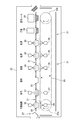
- FIG. 2 is a schematic plan view of the interior of the filling chamber 4 of the bottle aseptic filling machine according to the embodiment of the present invention.
- FIG. 2 shows a part of an aseptic filling machine in which the filling part, the sealing part and the discharging part are shielded by a single filling part chamber 4.
- the bottle 5, which is a sterilized container is conveyed into the filling chamber 4 from the wheel 10 in the air rinsing chamber 6 that shields the air rinsing portion.
- the bottles 5 to be conveyed are arranged in the order of the introduction wheel 11, the filling wheel 12, the intermediate wheel 13, the capper wheel 14, and the discharge wheel 15 from the upstream side to the downstream side. These wheels 11 to 15 are driven so as to perform rotational movement at substantially the same peripheral speed.
- scissor-shaped grippers for clamping/unclamping the neck of the bottle 5 are arranged at a predetermined pitch.
- the gripper is capable of turning together with the wheels 11 to 15 about the central axes of the wheels 11 to 15.
- the gripper has a known structure, it will not be described in detail, but the bottle 5 is transferred from the gripper of the upstream wheel to the gripper of the downstream wheel by opening and closing by the action of a cam or the like at a position adjacent to each other. It is like this. As a result, the bottle 5 continuously travels from the introduction wheel 11 to the discharge wheel 15 via the filling wheel 12, the capper wheel 14, and the like.
- the filling wheel 12 and the filling nozzle that rotates together with the filling wheel 12 are connected to the filling wheel 12 that is mounted horizontally on a vertical axis installed on the base, and a gripper is provided around the filling wheel 12.
- each filling nozzle is arranged vertically so that the mouth of the lower end of the filling nozzle faces the mouth of the bottle 5 held by the gripper.
- the filling nozzle may be fixed to the filling wheel 12, but may be vertically reciprocable. When reciprocating in the vertical direction is possible, the filling nozzle can be inserted into the bottle 5 to supply the beverage or the like as the content into the bottle 5.
- Beverages, etc. are stored in a storage tank (not shown) after being sterilized, and from there, they reach the filling nozzle through a pipeline, and in order to distribute the beverages, etc. supplied from the storage tank to the filling nozzles that rotate.
- the vertical axis is provided with an upper rotary joint and an upper manifold. Beverages and the like in the storage tank enter the empty chamber of the vertical axis, and are discharged from the filling nozzle into the bottle 5 via the upper rotary joint and the upper manifold.
- the filling nozzle is provided with a valve for supplying a desired amount of beverage or the like into the bottle 5.
- the aseptic filling machine is provided with a CIP processing device that performs a CIP process for cleaning the inside of the beverage supply system piping from the storage tank to the filling nozzle and a SIP processing device that performs a SIP process for sterilization.
- a cup-shaped opening/closing body for opening/closing the opening at the lower end of the filling nozzle is provided.
- the opening/closing body is arranged around the filling wheel 12 corresponding to each gripper and the filling nozzle.
- the opening/closing body is movable in the radial direction and the vertical direction of the filling wheel 12 by a cam device, an air cylinder device, etc.
- the opening/closing body retracts inward in the radial direction,
- the filling nozzle is blocked, the filling nozzle is moved to the outer side in the radial direction immediately below the filling nozzle, and then moved upward to close the mouth of the filling nozzle.
- the CIP processing device in addition to the opening/closing body, it is provided with a lower manifold, a lower rotary joint, a cleaning liquid tank, and a pump.
- the lower rotary joint is attached to the vertical axis.
- the lower manifold is fixed to the base side.
- the opening/closing body, the upper manifold, the lower manifold, etc. are connected by a pipe line.
- a capper for screwing the cap into the mouth portion of the bottle 5 filled with the beverage or the like is provided.
- the capper pivots together with the capper wheel 14 to screw a sterilized cap to the mouth of the bottle 5.
- the wheels in each chamber are simultaneously rotated at approximately the same number of rotations. If each chamber is equipped with a motor and the rotation of the wheel can be controlled for each chamber, rotate each chamber. By rotating according to the stage of COP processing and SOP processing of each chamber, COP processing and SOP processing of each chamber can be advanced rapidly. By rotating the wheel, the sterile water adhering to the device and the wall surface in the chamber can be quickly removed.
- the wheel clutch of the filling wheel 12 may be disengaged and the wheels other than the filling wheel 12 may be rotated. ..
- the sterilizing agent is injected into the filling chamber 4 to sterilize the device and the wall surface in the filling chamber 4, but when the sterilizing agent containing peracetic acid is injected, water remaining in the chamber is discharged. Therefore, it is necessary to prevent the concentration of peracetic acid in the bactericide containing peracetic acid from decreasing and the bactericidal effect from decreasing. Before spraying the sterilizing agent containing peracetic acid, it is preferable to further blow heated air into the filling chamber 4 to completely remove the remaining water, but it takes a long time.
- the cleaning liquid adhering to the wheels 11 to 15 and the devices attached to the wheels 11 to 15 is removed, and the bactericidal effect of the disinfectant containing peracetic acid is reduced. Can be suppressed.
- Removing the wash water by driving the transport device that transports the container means that in the aseptic filling machine for bottles, the heating unit, the molding unit, the sterilization unit, the filling unit such as the air rinse unit, the sealing unit, and the discharging unit other than the discharging unit. It is also carried out in a chamber that shields.
- the wheel is rotated in a chamber other than the filling chamber 4, the sterile water adhering to the endless chain and the attached spindle can be removed by operating the endless chain that conveys the preform in the heating unit.
- aseptic water adhering to the wheel, the mold attached to the wheel, the drawing rod, the valve block, etc. can be removed by rotating the wheel.
- the air blown into the chamber is preferably heated. Furthermore, the air blown into the chamber may be sterile air. This is performed by supplying aseptic heated air into the chamber 1 by the aseptic heated air supply device 16 provided at the upper part of the chamber 1 shown in FIG. The sterile heated air is obtained by heating the air from the blower 17 with the heating device 18 and sterilizing it with the filter 19.
- the aseptic heated air supply device 16 includes a blower 17, a heating device 18, and a filter 19.
- the SOP process is performed in the chamber.
- the SOP process may be carried out without the COP process.
- a sterilizing agent containing peracetic acid is sprayed into the chamber, and then a sterilizing agent containing peracetic acid is washed away by spraying sterile water. The contained bactericide is removed by drying.
- the injection of the disinfectant containing peracetic acid and the injection of the disinfectant containing hydrogen peroxide may be alternately performed. For example, after spraying a disinfectant containing peracetic acid, wash away the disinfectant containing peracetic acid with sterile water, drive the transport device that transports the container to remove the sterile water, and then spray a disinfectant containing hydrogen peroxide. Then, the germicide containing hydrogen peroxide is removed by drying.
- An SOP treatment comprising a step of spraying a disinfectant containing hydrogen peroxide, removing the disinfectant containing hydrogen peroxide by drying, spraying a disinfectant containing peracetic acid, and then washing away the disinfectant containing peracetic acid with sterile water.
- the injection of the disinfectant containing peracetic acid and the injection of the disinfectant containing hydrogen peroxide may not only be performed alternately, but may be performed multiple times.
- the injection of the disinfectant containing peracetic acid and the injection of the disinfectant containing hydrogen peroxide may be alternately performed.
- the disinfectant containing peracetic acid is a disinfectant whose main component is peracetic acid, and the peracetic acid concentration is 500 ppm or more, preferably 1000 ppm to 5000 ppm. In addition, it contains at least hydrogen peroxide and acetic acid.
- the bactericidal effect is enhanced by heating the bactericidal agent containing peracetic acid to 40° C. to 95° C., preferably 50° C. to 95° C.
- the germicide containing peracetic acid After injecting a germicide containing peracetic acid into the chamber, inject sterile water into the chamber.
- the germicide containing peracetic acid is washed out from the chamber by spraying sterile water.
- the water used to wash away the disinfectant containing peracetic acid must be sterile water. This is to maintain the sterilized state by the sterilizing agent containing peracetic acid.
- the transfer device that transfers the container in the chamber where the germicide containing peracetic acid has been washed away with sterile water.
- the wheels 11 to 15 for transporting the bottle 5 are rotated after the injection of sterile water into the chamber, and the wheels 11 to 15 and the wheels 11 to 15 are rotated by the centrifugal force generated by rotating the wheels 11 to 15. Sterile water adhering to the device rotating with the wheels 11-15 is removed.
- the germicide containing hydrogen peroxide is injected into the aseptic filling machine chamber. Before spraying the germicide containing hydrogen peroxide into the chamber, it is preferable to dry the inside of the chamber as much as possible. This is because in the wet state, hydrogen peroxide is dissolved in the remaining sterile water and the concentration of hydrogen peroxide is reduced, so that the sterilizing ability may not be exhibited.
- rotation and stop may be repeated.
- Sterile air can be at 50°C to 200°C.
- the downward flow of the sterile water adhering to the wall surface can be promoted, and the removal of the sterile water adhering to the wall surface can be accelerated.
- Aseptic air By supplying aseptic air to increase the pressure in the filling chamber 4 to 30 Pa to 200 Pa, aseptic water is efficiently removed.
- aseptic water is efficiently removed by raising the pressure in the other chambers in the same manner.
- the bactericide containing hydrogen peroxide to be sprayed preferably contains hydrogen peroxide in the range of 20% by mass to 65% by mass. If it is less than 20% by mass, the bactericidal power may be insufficient, and if it exceeds 65% by mass, handling becomes difficult for safety reasons.
- Aseptic heated air is blown into the chamber in order to gasify the hydrogen peroxide and sterilize the chamber after injecting the sterilizing agent containing hydrogen peroxide into the chamber.
- Aseptic heated air may be at 50°C to 200°C.
- the blowing of aseptic heated air into the chamber gasifies the hydrogen peroxide in the sterilizing agent containing hydrogen peroxide remaining in the chamber, and the microscopic gap where the sterilizing agent containing peracetic acid could not enter, or the injection did not reach The non-existent areas and peracetic acid resistant bacteria are sterilized.
- FIG. 3 shows a schematic elevation view of a tray aseptic filling machine according to an embodiment of the present invention.
- the container to be filled is a tray, but a cup-shaped container having a flange is a similar aseptic filling machine.
- the tray 20 supplied to the aseptic filling machine is held by the retainer 21.
- the retainer 21 has a flat plate portion, and a fitting hole into which the tray 20 is fitted is formed in the flat plate portion.
- the flange portion 22 of the tray 20 is held by the flat plate portion by inserting the container portion into the fitting hole of the retainer 21.
- a large number of retainers 21 are prepared and the tray is continuously conveyed horizontally to the surface of the flange 22.
- the retainer 21 is attached to a transport device that travels continuously.
- the continuously traveling transport device is attached to the endless chain 24 horizontally spanning between the sprocket wheels 23a and 23b at predetermined intervals.
- the tray 20 is transported in the aseptic filling machine by driving the endless chain 24 and continuously running while holding the retainer 21.
- the tray 20 By being transported in the chamber 25 of the aseptic filling machine shown in FIG. 3, the tray 20 is sterilized, filled with the contents, and sealed.
- the chamber 25 includes a sterilizing unit, a filling unit, and a sealing unit inside the chamber 25.
- the tray 20 supplied to the chamber 25 is held by a retainer 21 and preheated by blowing hot air from above and below by a preheating nozzle 26.
- the preheated tray 20 is sterilized by spraying the sterilizing agent from above and below by the sterilizing agent spraying nozzle 27.
- the tray 20 sprayed with the sterilizing agent is held for a predetermined time, and is then sterilized by activating the sterilizing agent attached to the surface of the tray 20 by the aseptic heated air sprayed from the drying air nozzle 28, and the sterilizing agent is dried. Are removed by. Then, the tray 20 is filled with the contents sterilized by the filling device 29, and the tray 20 filled with the contents is sealed by heat-sealing the lid member sterilized by the sealing device to the tray 20. The sealed tray 20 is discharged from the chamber 25.
- the COP process and the SOP process are performed in the chamber 25 before operating the aseptic filling machine.
- the transport device that transports the tray 20 is driven to remove the cleaning liquid and the sterile water attached to the transport device. .. That is, the endless chain 24 that conveys the retainer 21 that does not hold the tray 20 is driven.
- the cleaning liquid or sterile water attached to the endless chain 24 and the retainer 21 can be removed in a short time.
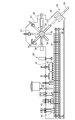
- FIG. 4 shows a schematic elevation view of an aseptic filling machine for paper containers according to an embodiment of the present invention.
- a sleeve supply device 32 introduces a sleeve 31, which is a tubular body having a wall surface formed by stacking at least paper and having a substantially rectangular cross section, into a chamber 33 by a sleeve supply device 32.
- the sleeve 31 is inserted into a mandrel 35 provided on the turret 34, leaving a portion necessary for closing.
- the sterilizing device 36 sterilizes the inner surface of the sleeve 31 on which the mandrel 35 is not inserted and which is closed, and the outer surface of the sleeve 31. After the sterilization, the remaining bactericide is removed by the hot air blown by the drying device 37.
- the sleeve 31 is folded by a folding device that bends the ruled line that forms the bottom of the paper container, and the portion that has been heated by the drying device 37 is pressed by the bottom sealing device 38. In this manner, the sleeve 31 is closed on one surface at the open end, and is molded into a bottomed tubular paper container.
- the germicide gas generated by the germicide gas generator 40 is jetted from the nozzle to the inner surface of the paper container.
- the bactericide sprayed on the paper container is removed by hot air sprayed from the hot air nozzle 41 onto the inner surface of the paper container.
- the sterilized paper container is filled with the contents sterilized by a separately provided device by the filling device 42. Further, the ruled line of the head of the paper container is folded by the head curl folding device, the inner surface is heated by the head heating device 43, and the head sealing device 44 press-bonds the paper container to seal the paper container.
- the sealed paper container is discharged from the chamber 33.
- the paper container is molded by being conveyed through the chamber 33 of the aseptic filling machine shown in FIG. 4, the molded paper container is sterilized, the contents are filled, and the container is sealed.
- the chamber 33 is internally provided with a paper container molding unit, a sterilization unit, a filling unit and a sealing unit.
- the COP process and the SOP process are performed in the chamber 33 before operating the aseptic filling machine.
- the transport device that transports the paper container is driven to remove the cleaning liquid and the sterile water attached to the transport device. That is, the turret 34 provided with the mandrel 35 is rotated in a state where the sleeve is not inserted in the mandrel 35, and the conveyor 39 that conveys the paper container that does not hold the paper container is driven.
- the turret 34 and the conveyor 39 By driving the turret 34 and the conveyor 39, the cleaning liquid or sterile water attached to the turret 34 and the conveyor 39 can be removed in a short time.
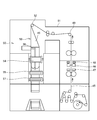
- FIG. 5 shows a schematic elevation view of a pouch aseptic filling machine according to an embodiment of the present invention.
- the pouch aseptic filling machine shown in FIG. 5 is a device for supplying a film, sterilizing the supplied film, molding the pouch, filling the pouch with the sterilized contents, and sealing the pouch. Therefore, it is provided with a traveling means for the packaging film 45 and a nozzle 46 for spraying a bactericide on both surfaces of the packaging film 45.
- the traveling means of the packaging film 45 is a drive device for continuously traveling the packaging film 45 from the feeding roll of the packaging film 45, and various guides arranged on the traveling path of the infeed roller and the packaging film 45.
- a roller, a guide roller that sandwiches the packaging film 45 from both sides thereof, and the like are included.
- a heated air blowing device 48 is provided which blows heated air onto both surfaces of the packaging film 45 after spraying the germicide.
- the sterilized packaging film 45 is turned by the roller 49 and conveyed to the bag making and filling unit 50.
- the bag making and filling unit 50 is shielded by the chamber 51, and the COP process and the SOP process are performed in the chamber 51 before operating the aseptic filling machine.
- the transporting direction of the packaging film 45 transported to the bag-making filling section 50 is changed downward by the roller 52.
- the packaging film 45 is folded by the former 53 so that both side edges along the transport direction are overlapped with each other.
- the folded packaging film 45 passes between a pair of vertical sealing rollers 54 (only the front side is shown in FIG. 5).
- the overlapping portions of both side edges of the packaging film 45 are heat-welded by the vertical sealing roller 54, whereby the packaging film 45 is formed into a tubular shape.
- the packaging film 45 is heated and welded at a constant interval in the transport direction by the pair of horizontal sealing rollers 55 to be sealed in the horizontal direction.
- Various sterilized contents are continuously supplied from the supply pipe 56 to the tubular packaging film 45 that is horizontally sealed. Will be done.
- notches are appropriately formed in each pouch, and perforations are further formed in the lateral direction, or the lateral sealing portion is cut by the cutting roller 57 to separate the pouches from each other. The cut pouch falls to the discharge part.
- the inside of the chamber 51 is subjected to COP processing and SOP processing before operating the aseptic filling machine.
- the packaging film 45 is passed through the chamber 51. This is because the packaging film 51 cannot be passed through without opening the chamber 51 in the SOP-treated chamber 51.
- the seal roller 55 and the cutting roller 57 are transporting devices for transporting the packaging film 45, and drive this transporting device to remove the cleaning liquid and sterile water adhering to the transporting device.
- the cleaning liquid or sterile water attached to the roller that is the transport device can be removed in a short time.
- the packaging film 45 is sprayed with a sterilizing agent by the sterilizing agent spraying device 46 and conveyed into the chamber 51.
- the packaging film 45 transported in the chamber 51 must be sterilized and transported in the chamber 51.
Landscapes
- Health & Medical Sciences (AREA)
- Epidemiology (AREA)
- Life Sciences & Earth Sciences (AREA)
- Animal Behavior & Ethology (AREA)
- General Health & Medical Sciences (AREA)
- Public Health (AREA)
- Veterinary Medicine (AREA)
- Chemical & Material Sciences (AREA)
- Chemical Kinetics & Catalysis (AREA)
- General Chemical & Material Sciences (AREA)
- Engineering & Computer Science (AREA)
- Mechanical Engineering (AREA)
- Apparatus For Disinfection Or Sterilisation (AREA)
- Filling Of Jars Or Cans And Processes For Cleaning And Sealing Jars (AREA)
Abstract
無菌充填機のチャンバー内のCOP処理及びSOP処理を行うに際して、過酢酸又は過酸化水素を含む殺菌剤の噴射前のチャンバー内に残存する洗浄液又は無菌水の除去を迅速に行う。 無菌充填機のチャンバー内の容器を搬送する搬送装置を駆動させて、COP処理の後の洗浄液又はSOP処理における無菌水を除去する。
Description
本発明は、食品、飲料等をPETボトル、紙容器、カップ、トレー、パウチ等の容器に充填するに先立ち、無菌充填機のチャンバー内を殺菌する方法に関する。
茶飲料、ミネラルウォーター、ジュース、スープ、栄養飲料、牛乳、乳飲料、つゆ、だし等をPETボトル、紙容器、カップ、トレー、パウチ等の容器に無菌充填する無菌充填機は、充填する内容物を切り替える際は、内容物供給系配管内を、まずCIP(Cleaning in Place)処理し、次にSIP(Sterilizing in Place)処理している。
CIP処理は、内容物充填経路の管路内から充填機の充填ノズルに至るまでの流路に、例えば水に苛性ソーダ等のアルカリ性薬剤を添加した洗浄液を流した後に、水に酸性薬剤を添加した洗浄液を流すことにより行われる。これにより、内容物充填経路内に付着した前回の内容物の残留物等が除去される。
SIP処理は、例えば、上記CIP処理で洗浄した流路内に蒸気や熱水等を流すことによって行われる。これにより、内容物充填経路内が殺菌され無菌状態とされる。
無菌充填機は、内容物を充填する容器を殺菌する殺菌部、殺菌された容器をリンスするリンス部、内容物殺菌装置により殺菌された内容物を殺菌された容器に充填する充填部、内容物が充填された容器を無菌雰囲気で密封する密封部等が設けられる。これらの部位は外部と遮蔽されるチャンバー内に設けられ、チャンバー内は無菌充填機の稼働中に無菌雰囲気に維持されなければならない。
充填部チャンバー及び密封部チャンバーの内部には前回の充填作業で充填した内容物の飛沫等が付着していることがあり、充填する内容物の種類を切り替える場合は、前回の充填作業でチャンバーの内壁、チャンバー内の充填機等の設備の外面に付着した内容物の飛沫等をチャンバー内から除去するため、チャンバー内に対してCOP(Cleaning out of Place)処理が行われる。COP処理は、例えば、水等を無菌チャンバー内にシャワー状に噴霧することにより行われる)。
さらに、内容物の種類を切り替える際の各種作業中に微生物が無菌チャンバー内に侵入するおそれもあるので、チャンバー内に対してSOP処理(Sterilizing out of Place)処理も行われる。従来、チャンバー内をSOP処理する方法として、チャンバー内に、過酢酸の噴霧、無菌水の噴霧、加熱エアの吹き込み、過酸化水素の噴霧、加熱エアの吹き込みを順に行うことが試みられている(特許文献1参照)。
また、特許文献2には熱水散布、加熱した過酢酸系殺菌剤の散布、加熱無菌水散布によるすすぎという工程によるチャンバー内殺菌も提案されている(特許文献2参照)。さらに、低濃度殺菌液の噴霧後に乾燥させるチャンバー内殺菌方法もある(特許文献3参照)。
特許文献4には、チャンバー内にアルカリ性洗浄剤を噴射し、無菌水を噴射するCOP処理を行った後に、過酢酸噴射、無菌水噴射、過酸化水素水噴射、ホットエア吹き出し、冷却エアの吹き出しというSOP処理を順次行うことが提案されている(特許文献4参照)。
殺菌された内容物を無菌雰囲気で殺菌された容器に充填し、密封する無菌充填機において、生産開始前に無菌充填機のチャンバー内の無菌雰囲気を確保するために、SOP処理が行われる。
SOP処理には殺菌剤として過酢酸又は過酸化水素が使用される。特許文献2及び特許文献3はこのようなSOP処理方法が記載されている。一方、特許文献1及び特許文献4には、過酢酸で殺菌した後に過酸化水素で殺菌するという、2段階のSOP処理が提案されている。過酢酸を含む殺菌剤は液体であり、液体に濡れる部分は殺菌されるが、液体が浸透しないパッキンの隙間等には過酸化水素による殺菌が有効である。過酸化水素水をチャンバー内に噴射した後に無菌加熱エアをチャンバー内に吹き込むが、このとき、チャンバー内に噴射された過酸化水素水が加熱され、気化して排気される。過酸化水素水中の過酸化水素が加熱され気化して、過酢酸を含む殺菌剤が浸透しなかった隙間にも入り込み、過酢酸を含む殺菌剤により殺菌されなかった箇所も殺菌することができる。
通常、過酢酸を含む殺菌剤がチャンバー内に噴射され、チャンバー内に噴射された過酢酸を含む殺菌剤を洗い流すために続けて無菌水が噴射され、その後に過酸化水素水がチャンバー内に噴射される。このとき、無菌水がチャンバー内に残存する状態で過酸化水素水をチャンバー内に噴射すると、過酸化水素水がチャンバー内に残存する無菌水と混合され、混合した液体中の過酸化水素濃度はチャンバー内に噴射した過酸化水素水の過酸化水素濃度よりも低下する。結果として、過酸化水素水の噴射による殺菌効果が低下するという傾向がある。そのため、通常、チャンバー内に残存する無菌水が自然乾燥され、又は無菌エアの吹き込みにより乾燥され、除去されるまで、チャンバー内への過酸化水素水の噴射は行われない。自然乾燥又は無菌エアによる乾燥によりチャンバー内の無菌水が除去されたのを目視により確認してからチャンバー内への過酸化水素水の噴射が行われる。
また、チャンバー内を洗浄液により洗浄し、洗浄液を水により洗い流すCOP処理の後にチャンバー内に過酢酸を含む殺菌剤で殺菌する場合も、過酢酸を含む殺菌剤中の過酢酸の濃度がチャンバーに残る水により低下すると、チャンバー内に噴射した過酢酸を含む殺菌剤の殺菌効果が低下する。
直前に噴射された無菌水がチャンバー内から除去されるのを待って、チャンバー内に過酢酸を含む殺菌剤及び過酸化水素水を噴射するのは、SOP処理時間の長時間化となり、無菌充填機の生産性を低下させている。無菌充填機のチャンバー内のSOP処理を行うに際して、過酢酸を含む殺菌剤及び過酸化水素水の噴射前の水の除去を迅速に行うことが求められている。本発明はこのような問題点を解消し、無菌充填機のチャンバー内をSOP処理するに際して、残存する水の除去を迅速に行い、SOP処理の時間を短縮することで、無菌充填機の生産性を向上させる無菌充填機チャンバー内の殺菌方法を提供することを目的とする。
本発明に係る無菌充填機チャンバー内の殺菌方法は、殺菌された容器に殺菌された内容物を無菌雰囲気で充填し、内容物が充填された容器を密封する無菌充填機において、前記無菌充填機の稼働前に行う無菌充填機チャンバー内の殺菌方法であって、前記無菌充填機チャンバー内に洗浄液を噴射することにより前記チャンバー内を洗浄後に、前記容器を搬送する搬送装置を駆動させて、搬送装置に付着する前記洗浄液を除去した後に、殺菌剤を前記無菌充填機チャンバー内に噴射することを特徴とする。
また、本発明に係る無菌充填機チャンバー内の殺菌方法は、前記殺菌剤が過酸化水素を含むと好適である。
また、本発明に係る無菌充填機チャンバー内の殺菌方法は、前記殺菌剤が過酢酸を含むと好適である。
また、本発明に係る無菌充填機チャンバー内の殺菌方法は、前記洗浄液が無菌水であると好適である。
また、本発明に係る無菌充填機チャンバー内の殺菌方法は、前記搬送装置を駆動させるときに、無菌充填機チャンバー内に無菌加熱エアを吹き込むと好適である。
また、本発明に係る無菌充填機チャンバー内の殺菌方法は、複数の前記無菌充填機チャンバー内の前記搬送装置を、前記無菌充填機チャンバーごとに駆動させると好適である。
本発明によれば、無菌充填機チャンバー内のCOP処理またはSOP処理の際に、無菌充填機チャンバー内に洗浄液を噴射した後に、容器を搬送する搬送装置を駆動させて、搬送装置に付着する洗浄水を除去することで、無菌充填機チャンバー内に残存する洗浄水を迅速に除去することができる。その後に、過酸化水素を含む殺菌剤又は過酢酸を含む殺菌剤を無菌充填機チャンバー内に噴射することで、噴射される殺菌剤中の過酸化水素又は過酢酸の濃度低下がなく、無菌充填機チャンバー内の殺菌を確実に行うことができる。さらに、SOP処理の時間を短縮することで、無菌充填機の生産性を向上させることができる。
無菌充填機は、通常、容器が供給され、供給された容器を殺菌する殺菌部、殺菌された容器に殺菌された内容物を無菌雰囲気で充填する充填部及び内容物が充填された容器を無菌雰囲気で密封する密封部を備える。しかし、無菌充填される容器により無菌充填機の構成は異なる。
例えば容器がボトルの場合、無菌充填機にプリフォームが供給され、プリフォームを成形温度まで加熱する加熱部、加熱されたプリフォームを容器に成形する成形部、成形されたボトルを検査する検査部、検査されたボトルを殺菌するボトル殺菌部、殺菌されたボトルをエアリンスするエアリンス部、殺菌されたボトルに内容物殺菌装置により殺菌された内容物を無菌雰囲気で充填する充填部、内容物が充填されたボトルを殺菌された蓋材により無菌雰囲気で密封する密封部及び密封されたボトルを排出する排出部からなる。ボトルの無菌充填機は検査部及びエアリンス部を備えなくても構わない。また、供給されたプリフォームを加熱する前に殺菌するプリフォーム殺菌部を有する無菌充填機もある。プリフォーム殺菌部を有する無菌充填機はボトル殺菌部を備えなくても構わない。
また、紙容器の場合、無菌充填機にスリーブが供給され、紙容器の外面を殺菌すると共に底部を成形する底部成形部、底部が成形された紙容器の内面を殺菌する殺菌部、内面が殺菌された紙容器に殺菌された内容物を充填する充填部、内容物が充填された紙容器を密封する密封部を備える。他の容器についても無菌充填機の構成は異なる。
無菌充填機を構成する各部はチャンバーにより遮蔽されている。ボトルの場合、加熱部と成形部は単一のチャンバーにより遮蔽されても構わない。また、密封部と排出部も単一のチャンバーにより遮蔽されても構わない。さらに、充填部、密封部及び排出部が単一のチャンバーにより遮蔽されても構わない。
紙容器の場合、底部成形部、殺菌部、充填部及び密封部は単一のチャンバーにより遮蔽される。しかし、底部成形部、殺菌部、充填部及び密封部をそれぞれ異なるチャンバーにより遮蔽しても構わない。無菌充填機が対象とする容器により各部の構成は異なるが、さらに各部を遮蔽するチャンバーも様々である。
ボトルの無菌充填機の稼働中には、ボトル殺菌部のチャンバー、エアリンス部のチャンバー、充填部のチャンバー、密封部のチャンバー及び排出部のチャンバーは、除菌フィルタにより無菌化された無菌エアが供給され、各チャンバー内の圧力を陽圧にすることで、無菌充填機の無菌性が維持される。陽圧に保持する圧力は、充填部のチャンバー内が最も高く、エアリンス部のチャンバー、ボトル殺菌部のチャンバーと上流に行くほど低く設定される。また、例えば、充填部のチャンバー内の圧力を20Pa~40Paとすると、他のチャンバー内の圧力は充填部のチャンバー内の圧力よりも低い。プリフォーム殺菌部を有する無菌充填機は、加熱部及び成形部もチャンバーに覆われ、加熱部チャンバー内及び成形部チャンバー内には無菌エアが供給され陽圧に保持される。
ボトル殺菌部のチャンバー、エアリンス部のチャンバー、充填部のチャンバー、密封部のチャンバー及び排出部のチャンバー内は、無菌充填機の稼働前にCOP処理及びSOP処理が行われる。そのため図1に示すように、無菌充填機のチャンバー1内には洗浄液及び過酢酸を含む殺菌剤を噴射する回転式ノズル2及び過酸化水素を含む殺菌剤を噴射する二流体ノズル3が設けられる。回転式ノズル2とは、送液圧により回転しながら供給される液体をチャンバー1内に噴射するノズルである。また、二流体ノズル3とは過酸化水素を含む殺菌剤と圧縮エアを供給し、圧縮エアの圧力により過酸化水素を含む殺菌剤をチャンバー1内に噴射するものである。チャンバー1内に設けられるノズルは回転式ノズル2及び二流体ノズル3に限定されるものではなく、洗浄剤、過酢酸を含む殺菌剤、無菌水及び過酸化水素を含む殺菌剤をチャンバー1内に噴射できるものであれば、他の構造のノズルでも構わない。
ボトルの場合、ボトル殺菌部のチャンバー内は無菌充填機稼働中に殺菌剤が噴霧されるため、SOP処理されなくても構わない。プリフォーム殺菌部を有する無菌充填機は、加熱部及び成形部を覆うチャンバー内のSOP処理が行われる。
ボトル以外の容器を対象とする無菌充填機は、殺菌部、充填部及び密封部が単一のチャンバーにより遮蔽されている例があり、この場合、単一のチャンバー内についてCOP処理及びSOP処理が行われる。
各チャンバー内をSOP処理する前に内容物が充填される充填部のチャンバーから下流のチャンバーはCOP処理される。内容物がチャンバー内に飛散して汚染が激しいチャンバー内は温水、熱水、アルカリ性洗浄液又は酸性洗浄液等の洗浄液を噴射することで、洗浄される。成形部及びボトル殺菌部のチャンバーは汚染が限定的であるため、COP処理しなくても構わない。
無菌充填機により内容物を容器に充填する連続運転の後、内容物を変更する場合又は、長時間の連続運転により、チャンバー内が内容物の飛沫により汚染された場合、無菌充填機の運転を停止して、無菌充填機のチャンバー内のCOP処理及びSOP処理を行う。内容物による汚染がないチャンバー内はSOP処理のみを行う。
内容物により汚染されたチャンバー1内を洗浄するCOP処理のため、先ずチャンバー内に、例えばアルカリ性洗浄液の噴射を行う。アルカリ性洗浄液とは、水酸化ナトリウム、水酸化カリウム等の無機塩基性化合物、又はエタノールアミン、ジエチルアミン等の有機塩基性化合物を含み、この他に、有機酸のアルカリ金属塩、アルカリ土類金属塩、及びアンモニウム塩、エチレンジアミン四酢酸等の金属イオン封鎖剤、アニオン系界面活性剤、カチオン系界面活性剤、ポリオキシエチレンアルキルフェニルエーテル類等の非イオン系界面活性剤、クメンスルホン酸ナトリウム等の可溶化剤、ポリアクリル酸等の酸系高分子の金属塩、腐食抑制剤、防腐剤、酸化防止剤、分散剤、消泡剤などを含んで構わない。
アルカリ性洗浄液の噴射を行った後に、酸性洗浄液の噴射を行っても構わない。酸性洗浄液とは、塩酸、硝酸、リン酸等の無機酸又は酢酸、蟻酸、オクタン酸、シュウ酸、クエン酸、コハク酸、グルコン酸等の有機酸であり、アニオン系界面活性剤、カチオン系界面活性剤、ポリオキシエチレンアルキルフェニルエーテル類等の非イオン系界面活性剤、クメンスルホン酸ナトリウム等の可溶化剤、ポリアクリル酸等の酸系高分子、腐食抑制剤、防腐剤、酸化防止剤、分散剤、消泡剤などを含んでも構わない。アルカリ性洗浄液の噴射を行っても内容物による汚染が洗浄されない場合、酸性洗浄液の噴射を行う。また、アルカリ性洗浄液の噴射を行わずに、酸性洗浄液を噴射させるだけでも構わない。アルカリ性洗浄液の噴射と、酸性洗浄液の噴射を、交互に繰り返し行っても構わない。
アルカリ性洗浄液及び酸性洗浄液を使用せずに、常温水、温水、熱水により洗浄しても構わない。また、アルカリ性洗浄液及び酸性洗浄液により洗浄した後に、アルカリ性洗浄液及び酸性洗浄液の洗い流しを兼ねて常温水、温水、熱水により洗浄しても構わない。これらの洗浄液の使用についてはその組み合わせ及び順序はどのようなものであっても構わない。ここで、温水とは40℃以上100℃未満であり、熱水とは100℃以上130℃までの範囲の温度の水である。
アルカリ性洗浄液を50℃以上に加温すると殺菌作用も有するため、50℃以上に加熱してチャンバー1内にアルカリ性洗浄液を噴射することで、殺菌効果も期待できる。
チャンバー1内に洗浄液を噴射させた後に、容器を搬送する搬送装置を駆動させて、搬送装置に付着する洗浄液を除去する。洗浄液が例えばアルカリ性洗浄液又は酸性洗浄液の場合、さらに常温水、温水、熱水である水を洗浄液として使用し、アルカリ性洗浄液又は酸性洗浄液を洗い流しても構わない。ここで水として無菌水を使用しても構わない。菌を含む水の噴射によりチャンバー内が菌により汚染されることを防止するためには、無菌水の使用が好ましい。無菌水とは水を121.1℃以上で4分以上加熱するか、無菌化フィルタを通すことで無菌化させた水である。次に行う殺菌剤の噴射に過酢酸を含む殺菌剤を使用する場合、水は一般水でも構わない。過酢酸を含む殺菌剤によりチャンバー1内に残存する水が殺菌されるためである。
アルカリ性洗浄液又は酸性洗浄液によりチャンバー内を洗浄した後に、チャンバー内に噴射する水は20℃~100℃、好ましくは60℃~100℃であるが、水の温度を60℃以上とすることにより、洗浄能力の向上以外にCOP処理によるアルカリ等の薬剤で損傷した耐熱性カビや耐熱性酵母に対して、殺菌効果が期待される。
ボトルを搬送する搬送装置の駆動について図2により説明する。図2は、本発明の実施の形態に係るボトルの無菌充填機の充填部チャンバー4内の概略平面図である。図2は充填部、密封部及び排出部が単一の充填部チャンバー4により遮蔽されている無菌充填機の一部を示す。殺菌された容器であるボトル5が、エアリンス部を遮蔽するエアリンス部チャンバー6内のホイール10から充填部チャンバー4内に搬送される。搬送されるボトル5は、上流側から下流側へと、導入ホイール11、充填ホイール12、中間ホイール13、キャッパーホイール14、排出ホイール15の順に並べられる。これらホイール11~15は互いに略同じ周速度で回転運動を行うように駆動される。
上記各ホイール11~15の回りには、ボトル5の首部をクランプ・アンクランプする鋏状のグリッパが所定のピッチで配置される。グリッパは各ホイール11~15と共に各ホイール11~15の中心軸の回りを旋回運動可能である。
グリッパは、公知の構造であるから詳しくは説明しないが、ホイール同士の隣接箇所でカム等の作用により開閉動作することにより、上流側ホイールのグリッパから下流側ホイールのグリッパへとボトル5を受け渡すようになっている。これにより、ボトル5は、導入ホイール11から充填ホイール12、キャッパーホイール14等を経て排出ホイール15へと連続走行する。
充填ホイール12と充填ホイール12と共に回転する充填ノズルは基台上に設置された垂直軸に水平に取り付けられる充填ホイール12に接続され、充填ホイール12の回りにはグリッパが備えられる。
また、充填ホイール12の回りには、各グリッパに対応して飲料等をボトル5に充填するためのパイプ状の充填ノズルが複数本設けられる。各充填ノズルは、グリッパに把持されたボトル5の口部に充填ノズルの下端の口が臨むように垂直に配置される。充填ノズルは充填ホイール12に対して固定されたものであってもよいが、垂直方向に往復運動可能なものであってもよい。垂直方向に往復運動可能な場合は、充填ノズルをボトル5内に挿入して内容物である飲料等をボトル5内に供給することができる。
飲料等は殺菌された後に図示しない貯留タンクに貯留され、そこから管路を通って充填ノズルに至るようになっており、貯留タンクから供給される飲料等を旋回運動する充填ノズルに配分するために、垂直軸には上部ロータリージョイント及び上部マニホルドが設けられる。貯留タンク内の飲料等は、垂直軸の空室内に入り、上部ロータリージョイント、上部マニホルドを経て充填ノズルからボトル5内に吐出される。
なお、充填ノズルには飲料等を所望量だけボトル5内に供給するためのバルブが設けられている。無菌充填機には、貯留タンクから充填ノズルに至る飲料供給系配管内を洗浄するCIP処理を行うCIP処理装置及び殺菌するSIP処理を行うSIP処理装置が設けられる。CIP処理及びSIP処理を行うために、充填ノズルの下端の口を開閉するためのカップ状の開閉体が設けられる。開閉体は、充填ホイール12の回りに、各グリッパ及び充填ノズルに対応して配置される。
開閉体は、カム装置、エアシリンダ装置等によって充填ホイール12の半径方向と垂直方向とに移動可能であり、充填ノズルから飲料等をボトル5内に供給する時は半径方向内側へと後退し、充填ノズルを遮蔽する時は充填ノズルの直下へと半径方向外側に移動し、続いて上昇して充填ノズルの口を塞ぐようになっている。
また、CIP処理装置を構成するものとして、開閉体のほか、下部マニホルドと、下部ロータリージョイントと、洗浄液タンクと、ポンプとを備える。下部ロータリージョイントは、垂直軸に取り付けられる。下部マニホルドは、基台側に固定される。これら開閉体、上部マニホルド、下部マニホルド等の間は管路で結ばれる。これらのCIP処理装置は充填ホイール12と共に回転する。
図2に示したキャッパーホイール14の回りには、図示しないが、飲料等が充填されたボトル5の口部にキャップをねじ込むためのキャッパーが設けられる。キャッパーは、キャッパーホイール14と共に旋回運動しつつ殺菌処理済のキャップをボトル5の口部に螺着するようになっている。
洗浄液により洗浄されたチャンバー内のホイール11~15の回転を行う。充填部チャンバー4内への洗浄液の噴射後にボトル5を搬送するホイール11~15を回転させて、ホイール11~15を回転させることにより発生する遠心力により、ホイール11~15及びホイール11~15と共に回転する装置に付着する洗浄液を除去する。
ホイール11~15の回転は、少なくとも無菌充填機の運転時のホイール回転速度の半分以上、好ましくは製造時の運転速度まで回転させる。各チャンバー内のホイールを同時に略同回転数で回転させる。チャンバーごとにモーターを備え、ホイールの回転をチャンバーごとに制御できる場合、チャンバーごとに回転させる。各チャンバーのCOP処理及びSOP処理の段階に応じて回転させることで、各チャンバーのCOP処理及びSOP処理を迅速に進めることができる。ホイールの回転を行うことで、チャンバー内の装置及び壁面に付着した無菌水を迅速に除去することができる。飲料供給系配管内のCIP処理又はSIP処理が行われているときは、充填ホイール12のホイールのクラッチを切って、充填ホイール12以外のホイールを回転させても構わない。
次に充填部チャンバー4内に殺菌剤を噴射させて、充填部チャンバー4内の装置及び壁面の殺菌を行うが、過酢酸を含む殺菌剤の噴射を行う場合、チャンバー内に残存している水により過酢酸を含む殺菌剤中の過酢酸の濃度が低下し、殺菌効果が低下することを防止する必要がある。過酢酸を含む殺菌剤の噴射を行う前に、さらに充填部チャンバー4内に加熱エアの吹き込みを行い、残存する水を完全に除去することが好ましいが、長時間を要する。ボトル5の搬送装置であるホイール11~15の回転を行うことで、ホイール11~15及びホイール11~15に付属する装置に付着する洗浄液を除去し、過酢酸を含む殺菌剤の殺菌効果の低下を抑制することができる。
ホイール11~15を回転させる場合、回転、停止を繰り返しても構わない。回転及び停止を繰り返すことで加速度が加わり、ホイール11~15及びホイール11~15に付属する装置に付着する洗浄液の除去が効率的に行われる。また、キャッパーのスピンドルを上下させ、スピンドルを保護しているベローズに付着した残水を除去させても良い。
容器を搬送する搬送装置を駆動させることで洗浄水を除去することは、ボトルの無菌充填機において、加熱部、成形部、殺菌部、エアリンス部等の充填部、密封部及び排出部以外の部を遮蔽するチャンバー内でも行われる。充填部チャンバー4以外のチャンバーにおいてもホイールを回転させるが、加熱部ではプリフォームを搬送する無端チェーンを運転することで、無端チェーン及び付属するスピンドルに付着した無菌水を除去することができる。成形部ではホイールとこれに付属する金型、延伸ロッド、バルブブロック等に付着する無菌水をホイールの回転を行うことで除去することができる。
容器を搬送する搬送装置を駆動させることで洗浄水を除去する際に、無菌充填機チャンバー内にエアを吹き込むことが好ましい。チャンバー内に無菌加熱エアを吹き込むことにより洗浄水の除去を促進することができ、短時間に洗浄水の除去を行うことができる。チャンバー内に吹き込むエアは加熱することが好ましい。さらに、チャンバー内に吹き込むエアは無菌エアでも構わない。これは、図1に示すチャンバー1の上部に設けられる無菌加熱エア供給装置16により、無菌加熱エアをチャンバー1内に供給することにより行われる。無菌加熱エアは、ブロア17によるエアを加熱装置18により加熱し、フィルタ19により無菌化することで得られる。無菌加熱エア供給装置16はブロア17、加熱装置18及びフィルタ19から成る。
洗浄液の噴射によりCOP処理が行われたチャンバー内の洗浄液を除去した後に、チャンバー内はSOP処理が行われる。ボトルの無菌充填機において、プリフォーム殺菌部を有する無菌充填機の加熱部及び成形部を覆うチャンバー内は内容物による汚染がないため、COP処理を行わずSOP処理のみ行っても構わない。SOP処理としては、過酢酸を含む殺菌剤をチャンバー内に噴射後、無菌水の噴射により過酢酸を含む殺菌剤を洗い流す、過酸化水素を含む殺菌剤をチャンバー内に噴射後、過酸化水素を含む殺菌剤を乾燥により除去することが行われる。
また、過酢酸を含む殺菌剤の噴射と過酸化水素を含む殺菌剤の噴射を交互に行うこともある。例えば、過酢酸を含む殺菌剤を噴射後、無菌水により過酢酸を含む殺菌剤を洗い流し、容器を搬送する搬送装置を駆動させて無菌水を除去した後、過酸化水素を含む殺菌剤を噴射し、過酸化水素を含む殺菌剤を乾燥により除去することである。
過酸化水素を含む殺菌剤を噴射し、過酸化水素を含む殺菌剤を乾燥により除去し、過酢酸を含む殺菌剤を噴射後、無菌水により過酢酸を含む殺菌剤を洗い流す工程からなるSOP処理もある。過酢酸を含む殺菌剤の噴射と過酸化水素を含む殺菌剤の噴射を交互に行うだけでなく、それぞれを複数回行っても構わない。
過酢酸を含む殺菌剤噴射後に無菌水を噴射し、その後過酸化水素を含む殺菌剤を噴射する場合、無菌水を噴射した後に容器を搬送する搬送装置を駆動させて無菌水を除去する。過酢酸を含む殺菌剤によるチャンバー内の殺菌は、過酢酸を含む殺菌剤が接触した箇所は完全に行われる。しかし、殺菌剤が入り込めない微細な隙間や、噴射が届かない箇所、積極的に過酢酸を含む殺菌剤で殺菌できない箇所(たとえばHEPAフィルター)や過酢酸耐性菌(パエニバチルス属やセレウス菌など)は殺菌されないおそれがある。よって、過酸化水素を含む殺菌剤から発生する過酸化水素ガスにより過酢酸を含む殺菌剤では殺菌されないおそれのある、殺菌剤が入り込めない微細な隙間や、噴射が届かない箇所を殺菌するために、過酢酸を含む殺菌剤の噴射と過酸化水素を含む殺菌剤の噴射を交互に行っても構わない。
ここで、過酢酸を含む殺菌剤とは、過酢酸が主成分である殺菌剤であり、過酢酸濃度が500ppm以上で、好ましくは1000ppm~5000ppmである。他に少なくとも過酸化水素及び酢酸を含む。このとき、過酢酸を含む殺菌剤を40℃~95℃、好ましくは50℃~95℃に加温することで殺菌効果が高まる。
チャンバー内に過酢酸を含む殺菌剤の噴射を行った後に、チャンバー内に無菌水の噴射を行う。無菌水の噴射を行うことで、過酢酸を含む殺菌剤をチャンバー内から洗い流す。ここでは、過酢酸を含む殺菌剤を洗い流す水は無菌水でなければならない。過酢酸を含む殺菌剤により殺菌された状態を維持するためである。
過酢酸を含む殺菌剤が無菌水により洗い流されたチャンバー内の容器を搬送する搬送装置を駆動させる。ボトルの無菌充填機では、チャンバー内への無菌水の噴射後にボトル5を搬送するホイール11~15を回転させて、ホイール11~15を回転させることにより発生する遠心力により、ホイール11~15及びホイール11~15と共に回転する装置に付着する無菌水を除去する。
無菌水を除去した後に、無菌充填機チャンバー内に過酸化水素を含む殺菌剤の噴射を行う。チャンバー内に過酸化水素を含む殺菌剤の噴射を行う前に、チャンバー内を出来るだけ乾燥させることが好ましい。濡れた状態の場合、残存する無菌水に過酸化水素が溶解し、過酸化水素の濃度が低下するため、殺菌能力が発揮されないおそれがあるためである。
各チャンバー内に残存する無菌水を短時間で効率良く除去するために、各チャンバー内のホイールを回転させるが、ホイールを回転させる回転速度は、生産時の運転速度まで上げることが好ましい。また、回転と停止を繰り返し行っても構わない。ホイールを回転させる際に、外部から菌が侵入しないように、無菌エアを供給しながら行うことが好ましい。さらに、無菌水の除去を速めるために無菌エアを加熱することが、さらに好ましい。無菌エアは50℃から200℃とすることができる。ホイールを回転させることで、ホイール及びホイールと共に回転する装置に付着する無菌水を除去することができるが、ホイールを回転させることで発生するホイール周辺の空気の流れがチャンバーの壁面に衝突することで、壁面に付着する無菌水の下方向への流れを促進し、壁面に付着する無菌水の除去も早めることができる。無菌エアを供給することにより、充填部チャンバー4内の圧力を30Pa~200Paまで上げると無菌水の除去が効率的に行われる。また、他のチャンバー内の圧力も同様に上げることで無菌水の除去が効率的に行われる。
上述したように、ホイール回転中に無菌加熱エアをチャンバー内に吹き込むことが好ましいが、ホイールの回転を停止した後にも無菌加熱エアをチャンバー内に吹き込むことで、チャンバー内に残存する無菌水の除去を早めることができる。
チャンバー内の無菌水を除去した後に、チャンバー内に過酸化水素を含む殺菌剤の噴射を行う。噴射させる過酸化水素を含む殺菌剤は、過酸化水素を20質量%~65質量%の範囲で含むことが適当である。20質量%未満では殺菌力が不足する場合があり、65質量%を超えると安全上、扱いが困難となる。過酸化水素を含む殺菌剤の噴射を行うことで、過酢酸を含む殺菌剤の噴射により殺菌できなかった箇所及び過酢酸耐性菌を含む菌を殺菌する。
チャンバー内に過酸化水素を含む殺菌剤の噴射を行った後に過酸化水素をガス化させてチャンバー内を殺菌するために、チャンバー内に無菌加熱エアの吹き込みを行う。無菌加熱エアは50℃から200℃とすることができる。チャンバー内への無菌加熱エアの吹き込みによりチャンバー内に残存する過酸化水素を含む殺菌剤中の過酸化水素がガス化し、過酢酸を含む殺菌剤が入り込めなかった微細な隙間や、噴射が届かない箇所や過酢酸耐性菌が殺菌される。
チャンバー内への無菌加熱エアの吹き込みにより、チャンバー内の過酸化水素を含む殺菌剤が除去されたことを確認した後に、残存する過酸化水素を除去し、無菌加熱エアの吹き込みにより昇温したチャンバー内を冷却するために常温の無菌エアをチャンバー内に吹き込むことで、チャンバー内の換気・冷却を行う。
これまで、ボトルの無菌充填機を中心に述べてきたが、ボトル以外のカップ、トレー、紙容器又はパウチのような容器の無菌充填機においても、容器を搬送する搬送装置を駆動させることは洗浄液又は無菌水の除去を短時間に行うため、無菌充填機の生産性を向上させることができる。
図3に本発明の実施の形態に係るトレーの無菌充填機の概略立面図を示す。図3に示す無菌充填機は充填する容器がトレーであるが、フランジを有するカップ形状の容器であっても同様の形態の無菌充填機である。無菌充填機に供給されるトレー20は、リテーナ21に保持される。リテーナ21は平板部を有し、平板部にトレー20が嵌り込む嵌入孔が形成されている。トレーは、容器部がリテーナ21の嵌入穴に挿入されることにより、トレー20のフランジ22が平板部に保持される。リテーナ21は多数用意され、トレーをフランジ22の面と水平に連続搬送させる。リテーナ21は連続走行する搬送装置に取り付けられる。連続走行する搬送装置とは、スプロケットホイール23a、23b間に水平に掛け渡される無端チェーン24に所定の間隔で取り付けられる。無端チェーン24の駆動により、リテーナ21を保持しつつ連続走行することで、トレー20が無菌充填機内で搬送される。
図3に示す無菌充填機のチャンバー25内を搬送されることで、トレー20は殺菌され、内容物が充填され、密封される。チャンバー25は殺菌部、充填部及び密封部をチャンバー25内に備える。チャンバー25に供給されるトレー20はリテーナ21に保持され、予備加熱用ノズル26により上下から熱風を吹き付けられることで予備加熱される。予備加熱されたトレー20は、殺菌剤吹き付けノズル27により上下から殺菌剤が吹き付けられることで殺菌される。殺菌剤が吹き付けられたトレー20は、所定時間保持された後、乾燥エアノズル28から吹き付けられる無菌加熱エアによりトレー20の表面に付着する殺菌剤が活性化されることで殺菌され、殺菌剤は乾燥により除去される。その後、充填装置29により殺菌された内容物がトレー20に充填され、内容物が充填されたトレー20は、密封装置により殺菌された蓋材がトレー20に熱シールされることにより密封される。密封されたトレー20はチャンバー25から排出される。
チャンバー25内は無菌充填機を運転する前に、COP処理及びSOP処理が行われる。この過程において、COP処理の後の洗浄水の除去又はSOP処理における無菌水の除去を行う際に、トレー20を搬送する搬送装置を駆動させて、搬送装置に付着する洗浄液及び無菌水を除去する。すなわち、トレー20を保持していないリテーナ21を搬送する無端チェーン24を駆動させる。無端チェーンチェーン24を駆動させることで、無端チェーン24及びリテーナ21に付着する洗浄液又は無菌水を短時間に除去することができる。
図4に本発明の実施の形態に係る紙容器の無菌充填機の概略立面図を示す。少なくとも紙を積層してなる壁面を有すると共に断面が略矩形状の筒状体であるスリーブ31はスリーブ供給装置32により、チャンバー33の中に導入される。スリーブ31は閉塞するために必要な部分を残し、ターレット34に設けられたマンドレル35に挿入される。さらに、殺菌装置36により、マンドレル35が挿入されていないスリーブ31の閉塞される側の内面及び、スリーブ31の外面が殺菌される。殺菌後、残存する殺菌剤は乾燥装置37により吹き付けられる熱風により除去される。
さらに、スリーブ31は、紙容器の底部を形成する罫線を底部くせ折り装置により折り込まれ、乾燥装置37により熱せられていた部分が底部シール装置38により圧着される。このようにしてスリーブ31は、開放端の一方の面を閉塞され、有底筒状の紙容器に成型される。
成型された紙容器はコンベア39により間欠的に搬送されながら、殺菌剤のガス生成器40によって生成された殺菌剤のガスが、ノズルから紙容器の内面に噴射される。紙容器に吹き付けられた殺菌剤は、ホットエアノズル41から紙容器の内面に吹き付けられるホットエアにより除去される。殺菌された紙容器には、別に設けられた装置により殺菌された内容物が、充填装置42により充填される。さらに、頭部くせ折り装置により紙容器の頭部の罫線が折り込まれ、頭部加熱装置43により内面が加熱され、頭部シール装置44により圧着され、紙容器は密封される。密封された紙容器はチャンバー33から排出される。図4に示す無菌充填機のチャンバー33内を搬送されることで紙容器は成形され、成形された紙容器は殺菌され、内容物が充填され、密封される。チャンバー33は内部に、紙容器成形部、殺菌部、充填部及び密封部を備える。
チャンバー33内は無菌充填機を運転する前に、COP処理及びSOP処理が行われる。この過程において、COP処理の後の洗浄液の除去又はSOP処理における無菌水の除去を行う際に、紙容器を搬送する搬送装置を駆動させて、搬送装置に付着する洗浄液及び無菌水を除去する。すなわち、マンドレル35が備えられるターレット34をマンドレル35にスリーブが挿入されていない状態で回転させ、紙容器を保持しない紙容器を搬送するコンベア39を駆動させる。ターレット34及びコンベア39を駆動させることで、ターレット34及びコンベア39に付着する洗浄液又は無菌水を短時間に除去することができる。
図5に本発明の実施の形態に係るパウチの無菌充填機の概略立面図を示す。図5に示すパウチの無菌充填機は、フィルムを供給し、供給されたフィルムを殺菌し、パウチを成形すると共にパウチに殺菌された内容物を充填し、密封する装置である。したがって、包装用フィルム45の走行手段と、包装用フィルム45の両面に殺菌剤を吹き付けるノズル46とを具備する。包装用フィルム45の走行手段は、包装用フィルム45の繰り出しロールから包装用フィルム45を連続走行させるための駆動装置であり、インフィードローラ、包装用フィルム45の走行路上に配置された各種のガイドローラ、包装用フィルム45をその両面から挟むガイドローラ等が含まれる。
繰り出しロールから繰り出された包装用フィルム45を殺菌剤吹き付けノズル46に案内するガイドローラ及び包装用フィルム45に殺菌剤を吹き付ける前に包装用フィルム45を加熱する予備加熱装置47及び包装用フィルム45に殺菌剤を吹き付けた後に包装用フィルム45の両面に加熱エアを吹き付ける加熱エア吹き付け装置48が設けられる。
殺菌された包装用フィルム45はローラ49により方向転換され、製袋充填部50に搬送される。製袋充填部50はチャンバー51により遮蔽され、無菌充填機を運転する前にチャンバー51内はCOP処理及びSOP処理が行われる。製袋充填部50に搬送された包装用フィルム45は、ローラ52により搬送方向が下方向に変更される。その後、包装用フィルム45はフォーマー53により搬送方向に沿った両側縁を互いに重ね合わせるように折り込まれる。折り込まれた包装用フィルム45は一対の縦シール用ローラ54(図5では手前側のみ図示されている。)の間を通過する。その際、縦シール用ローラ54により包装用フィルム45の両側縁の重複部分が加熱溶着され、それにより包装用フィルム45が筒状に形成される。その後、包装用フィルム45は、一対の横シール用ローラ55により搬送方向に対して一定の間隔で加熱溶着されて横方向にシールされる。横シールされる筒状となっている包装用フィルム45には、供給管56から殺菌された各種の内容物が連続的に供給されており、横シールは内容物の存在する箇所を液中シールすることとなる。その後、各パウチにはノッチが適宜形成され、さらに横方向にミシン目が入れられるか、又は切断ローラ57により横方向シール部がカットされてパウチが相互に分離される。カットされたパウチは排出部に落下する。
チャンバー51内は無菌充填機を運転する前に、COP処理及びSOP処理が行われる。SOP処理が行われる際、チャンバー51内には包装用フィルム45がチャンバー51内に通される。SOP処理されたチャンバー51内にチャンバー51を開放しないで包装用フィルム51を通すことができないためである。この過程において、COP処理の後の洗浄水の除去又はSOP処理における無菌水の除去を行う際に、包装用フィルム45を搬送する包装用フィルムをニップして搬送するローラ、縦シールローラ54、横シールローラ55及び切断ローラ57は包装用フィルム45を搬送する搬送装置であり、この搬送装置を駆動させて、搬送装置に付着する洗浄液及び無菌水を除去する。すなわち、成形用フィルム45の搬送装置であるローラに成形用フィルムを繰り出しながら、駆動させることで、搬送装置であるローラに付着する洗浄液又は無菌水を短時間に除去することができる。このとき、包装用フィルム45は殺菌剤吹き付け装置46により殺菌剤が吹き付けられてチャンバー51内に搬送される。チャンバー51内のSOP処理を確実に行うためには、チャンバー51内に搬送される包装用フィルム45を殺菌してチャンバー51内に搬送されなければならない。
本発明は以上説明したように構成されるが、上記実施の形態に限定されるものではなく、本発明の要旨の範囲内において種々変更可能である。
1…チャンバー
2…回転式ノズル
3…二流体ノズル
4…充填部チャンバー
11…導入ホイール
12…充填ホイール
14…キャッパーホイール
15…排出ホイール
2…回転式ノズル
3…二流体ノズル
4…充填部チャンバー
11…導入ホイール
12…充填ホイール
14…キャッパーホイール
15…排出ホイール
Claims (6)
- 殺菌された容器に殺菌された内容物を無菌雰囲気で充填し、内容物が充填された容器を密封する無菌充填機において、
前記無菌充填機の稼働前に行う無菌充填機チャンバー内の殺菌方法であって、
前記無菌充填機チャンバー内に洗浄液を噴射することにより前記チャンバー内を洗浄後に、前記容器を搬送する搬送装置を駆動させて、搬送装置に付着する前記洗浄液を除去した後に、殺菌剤を前記無菌充填機チャンバー内に噴射することを特徴とする無菌充填機チャンバー内の殺菌方法。 - 請求項1に記載の無菌充填機チャンバー内の殺菌方法において、前記殺菌剤が過酸化水素を含むことを特徴とする無菌充填機チャンバー内の殺菌方法。
- 請求項1に記載の無菌充填機チャンバー内の殺菌方法において、前記殺菌剤が過酢酸を含むことを特徴とする無菌充填機チャンバー内の殺菌方法。
- 請求項1乃至請求項3のいずれか1項に記載の無菌充填機チャンバー内の殺菌方法において、前記洗浄液が無菌水であることを特徴とする無菌充填機チャンバー内の殺菌方法。
- 請求項1乃至請求項4のいずれか1項に記載の無菌充填機チャンバー内の殺菌方法において、前記搬送装置を駆動させるときに、無菌充填機チャンバー内に無菌加熱エアを吹き込むことを特徴とする無菌充填機チャンバー内の殺菌方法。
- 請求項1乃至請求項5のいずれか1項に記載の無菌充填機チャンバーの殺菌方法において、
複数の前記無菌充填機チャンバー内の前記搬送装置を、前記無菌充填機チャンバーごとに駆動させることを特徴とする無菌充填機チャンバー内の殺菌方法。
Priority Applications (5)
| Application Number | Priority Date | Filing Date | Title |
|---|---|---|---|
| CN202311289143.4A CN117427196A (zh) | 2018-12-12 | 2019-12-09 | 无菌填充机腔室内的杀菌方法 |
| CN201980079679.9A CN113164634B (zh) | 2018-12-12 | 2019-12-09 | 无菌填充机腔室内的杀菌方法 |
| EP19896507.1A EP3895744A4 (en) | 2018-12-12 | 2019-12-09 | PROCEDURE FOR SANITIZING AN ASEPTIC FILLING MACHINE CHAMBER |
| US17/309,383 US11857690B2 (en) | 2018-12-12 | 2019-12-09 | Method for sterilizing interior of aseptic filler chamber |
| US18/507,286 US20240075177A1 (en) | 2018-12-12 | 2023-11-13 | Method for sterilizing interior of aseptic filler chamber |
Applications Claiming Priority (2)
| Application Number | Priority Date | Filing Date | Title |
|---|---|---|---|
| JP2018232801A JP6729671B2 (ja) | 2018-12-12 | 2018-12-12 | 無菌充填機チャンバー内の殺菌方法 |
| JP2018-232801 | 2018-12-12 |
Related Child Applications (2)
| Application Number | Title | Priority Date | Filing Date |
|---|---|---|---|
| US17/309,383 A-371-Of-International US11857690B2 (en) | 2018-12-12 | 2019-12-09 | Method for sterilizing interior of aseptic filler chamber |
| US18/507,286 Continuation US20240075177A1 (en) | 2018-12-12 | 2023-11-13 | Method for sterilizing interior of aseptic filler chamber |
Publications (1)
| Publication Number | Publication Date |
|---|---|
| WO2020122015A1 true WO2020122015A1 (ja) | 2020-06-18 |
Family
ID=71077270
Family Applications (1)
| Application Number | Title | Priority Date | Filing Date |
|---|---|---|---|
| PCT/JP2019/048082 WO2020122015A1 (ja) | 2018-12-12 | 2019-12-09 | 無菌充填機チャンバー内の殺菌方法 |
Country Status (5)
| Country | Link |
|---|---|
| US (2) | US11857690B2 (ja) |
| EP (1) | EP3895744A4 (ja) |
| JP (1) | JP6729671B2 (ja) |
| CN (2) | CN113164634B (ja) |
| WO (1) | WO2020122015A1 (ja) |
Families Citing this family (1)
| Publication number | Priority date | Publication date | Assignee | Title |
|---|---|---|---|---|
| CN113650884B (zh) * | 2021-07-27 | 2023-08-29 | 上海观道生物科技有限公司 | 一种中药汤剂包装方法 |
Citations (5)
| Publication number | Priority date | Publication date | Assignee | Title |
|---|---|---|---|---|
| JPH11208782A (ja) | 1998-01-23 | 1999-08-03 | Dainippon Printing Co Ltd | 充填機の滅菌方法及びその滅菌装置 |
| JP2010189034A (ja) | 2009-02-18 | 2010-09-02 | Mitsubishi Heavy Industries Food & Packaging Machinery Co Ltd | 無菌充填機のチャンバー殺菌方法 |
| JP2011147673A (ja) | 2010-01-22 | 2011-08-04 | Toyo Seikan Kaisha Ltd | 空間表面の殺菌方法及び殺菌システム |
| JP2014055026A (ja) | 2012-09-13 | 2014-03-27 | Dainippon Printing Co Ltd | 無菌充填用チャンバ内の滅菌方法及び装置 |
| JP2017154822A (ja) * | 2017-04-20 | 2017-09-07 | 大日本印刷株式会社 | 無菌充填装置及びその浄化方法 |
Family Cites Families (17)
| Publication number | Priority date | Publication date | Assignee | Title |
|---|---|---|---|---|
| JPH0551088A (ja) | 1991-08-29 | 1993-03-02 | Shikoku Kakoki Co Ltd | 無菌充填機 |
| JP3483776B2 (ja) | 1998-08-11 | 2004-01-06 | 株式会社古川製作所 | 真空包装機の洗浄装置 |
| KR20030087803A (ko) * | 2002-05-10 | 2003-11-15 | 삼성전자주식회사 | 반도체장치 제조용 화학기상증착 설비의 콘베이어 벨트세정장치 |
| DE202007018501U1 (de) * | 2007-01-08 | 2008-10-23 | Aquagroup Ag | Reinigung von Getränkeabfüllanlagen |
| CN101929793B (zh) * | 2010-05-11 | 2012-02-15 | 赫得纳米科技(昆山)有限公司 | 用于喷淋清洗机的自动化除水装置 |
| CN101985318A (zh) * | 2010-09-02 | 2011-03-16 | 上海普丽盛轻工设备有限公司 | 无菌包装系统的消毒杀菌处理装置及消毒杀菌处理方法 |
| CN202063704U (zh) * | 2011-03-29 | 2011-12-07 | 北京洲际资源环保科技有限公司 | 一种啤酒包装生产线 |
| DE102011102090B4 (de) * | 2011-05-19 | 2018-02-08 | Khs Corpoplast Gmbh | Verfahren zum Reinigen und/oder Desinfizieren einer Vorrichtung zur Herstellung von mit einem flüssigen Füllgut gefüllten Behältern sowie Vorrichtung |
| JP6233315B2 (ja) * | 2012-11-16 | 2017-11-22 | 大日本印刷株式会社 | 飲料充填装置の浄化方法 |
| KR101504422B1 (ko) * | 2013-07-23 | 2015-03-19 | 주식회사 포스코 | 벨트 컨베이어용 벨트 청소장치 |
| CN103416482B (zh) * | 2013-08-13 | 2015-06-03 | 常州大学 | 水果保鲜加工的流水线装置及方法 |
| JP6439919B2 (ja) * | 2013-11-14 | 2018-12-19 | 大日本印刷株式会社 | プリフォームの殺菌方法及び装置 |
| CN204842373U (zh) | 2015-02-05 | 2015-12-09 | 毕节市烟草公司七星关区分公司 | 一种漂浮育苗穴盘清洗消毒设备 |
| EP3693331A1 (en) * | 2015-09-17 | 2020-08-12 | Dai Nippon Printing Co., Ltd. | Method of decontaminating an aseptic filling apparatus |
| JP6213621B1 (ja) * | 2016-07-07 | 2017-10-18 | 大日本印刷株式会社 | スリーブの殺菌方法及び装置 |
| JP7428464B2 (ja) | 2017-05-10 | 2024-02-06 | 大日本印刷株式会社 | 無菌充填機及び無菌充填方法 |
| WO2018207787A1 (ja) | 2017-05-10 | 2018-11-15 | 大日本印刷株式会社 | 無菌充填機及び無菌充填方法 |
-
2018
- 2018-12-12 JP JP2018232801A patent/JP6729671B2/ja active Active
-
2019
- 2019-12-09 US US17/309,383 patent/US11857690B2/en active Active
- 2019-12-09 CN CN201980079679.9A patent/CN113164634B/zh active Active
- 2019-12-09 EP EP19896507.1A patent/EP3895744A4/en active Pending
- 2019-12-09 WO PCT/JP2019/048082 patent/WO2020122015A1/ja unknown
- 2019-12-09 CN CN202311289143.4A patent/CN117427196A/zh active Pending
-
2023
- 2023-11-13 US US18/507,286 patent/US20240075177A1/en active Pending
Patent Citations (5)
| Publication number | Priority date | Publication date | Assignee | Title |
|---|---|---|---|---|
| JPH11208782A (ja) | 1998-01-23 | 1999-08-03 | Dainippon Printing Co Ltd | 充填機の滅菌方法及びその滅菌装置 |
| JP2010189034A (ja) | 2009-02-18 | 2010-09-02 | Mitsubishi Heavy Industries Food & Packaging Machinery Co Ltd | 無菌充填機のチャンバー殺菌方法 |
| JP2011147673A (ja) | 2010-01-22 | 2011-08-04 | Toyo Seikan Kaisha Ltd | 空間表面の殺菌方法及び殺菌システム |
| JP2014055026A (ja) | 2012-09-13 | 2014-03-27 | Dainippon Printing Co Ltd | 無菌充填用チャンバ内の滅菌方法及び装置 |
| JP2017154822A (ja) * | 2017-04-20 | 2017-09-07 | 大日本印刷株式会社 | 無菌充填装置及びその浄化方法 |
Also Published As
| Publication number | Publication date |
|---|---|
| EP3895744A4 (en) | 2022-09-07 |
| US20240075177A1 (en) | 2024-03-07 |
| JP2020093813A (ja) | 2020-06-18 |
| CN113164634B (zh) | 2023-10-20 |
| CN113164634A (zh) | 2021-07-23 |
| EP3895744A1 (en) | 2021-10-20 |
| JP6729671B2 (ja) | 2020-07-22 |
| US11857690B2 (en) | 2024-01-02 |
| CN117427196A (zh) | 2024-01-23 |
| US20220031891A1 (en) | 2022-02-03 |
Similar Documents
| Publication | Publication Date | Title |
|---|---|---|
| CN112512955B (zh) | 无菌填充机及其净化方法 | |
| JP7434749B2 (ja) | 無菌充填機の無菌水供給配管内殺菌方法及び殺菌装置 | |
| US11884529B2 (en) | Aseptic filling apparatus and method for cooling filling valve of aseptic filling apparatus | |
| US20240075177A1 (en) | Method for sterilizing interior of aseptic filler chamber | |
| JP7106832B2 (ja) | 無菌充填機における殺菌方法 | |
| JP6970395B2 (ja) | 無菌充填機チャンバー内の殺菌方法 | |
| JP6970393B2 (ja) | 無菌充填機チャンバー内の殺菌方法 | |
| JP6970394B2 (ja) | 無菌充填機チャンバー内の殺菌方法 | |
| JP6927359B2 (ja) | 無菌充填機及びその浄化方法 | |
| CN115210145B (zh) | 杀菌方法 | |
| JP6394644B2 (ja) | キャップ殺菌装置および内容物充填システム | |
| JP6735705B2 (ja) | 無菌充填装置及びその浄化方法 | |
| WO2023032754A1 (ja) | 密封容器外面洗浄装置の洗浄方法及び無菌充填機 | |
| JP6292262B2 (ja) | キャップ殺菌装置、内容物充填システムおよびキャップ殺菌方法 | |
| JP2017095115A (ja) | 無菌充填装置及びその浄化方法 | |
| JP2006089143A (ja) | 容器の殺菌方法及び装置 | |
| JP2018016363A (ja) | キャップ殺菌装置、内容物充填システムおよびキャップ殺菌方法 |
Legal Events
| Date | Code | Title | Description |
|---|---|---|---|
| 121 | Ep: the epo has been informed by wipo that ep was designated in this application |
Ref document number: 19896507 Country of ref document: EP Kind code of ref document: A1 |
|
| NENP | Non-entry into the national phase |
Ref country code: DE |
|
| ENP | Entry into the national phase |
Ref document number: 2019896507 Country of ref document: EP Effective date: 20210712 |