WO2020121997A1 - 人工聴覚器及び刺入型圧電デバイス - Google Patents
人工聴覚器及び刺入型圧電デバイス Download PDFInfo
- Publication number
- WO2020121997A1 WO2020121997A1 PCT/JP2019/048010 JP2019048010W WO2020121997A1 WO 2020121997 A1 WO2020121997 A1 WO 2020121997A1 JP 2019048010 W JP2019048010 W JP 2019048010W WO 2020121997 A1 WO2020121997 A1 WO 2020121997A1
- Authority
- WO
- WIPO (PCT)
- Prior art keywords
- vibrating
- electrode
- vibration
- pair
- support
- Prior art date
- Legal status (The legal status is an assumption and is not a legal conclusion. Google has not performed a legal analysis and makes no representation as to the accuracy of the status listed.)
- Ceased
Links
- IBJXPBRYKQWVEM-UHFFFAOYSA-N CC(C(C=CC1)=C1C=C)=O Chemical compound CC(C(C=CC1)=C1C=C)=O IBJXPBRYKQWVEM-UHFFFAOYSA-N 0.000 description 1
Images




Classifications
-
- A—HUMAN NECESSITIES
- A61—MEDICAL OR VETERINARY SCIENCE; HYGIENE
- A61F—FILTERS IMPLANTABLE INTO BLOOD VESSELS; PROSTHESES; DEVICES PROVIDING PATENCY TO, OR PREVENTING COLLAPSING OF, TUBULAR STRUCTURES OF THE BODY, e.g. STENTS; ORTHOPAEDIC, NURSING OR CONTRACEPTIVE DEVICES; FOMENTATION; TREATMENT OR PROTECTION OF EYES OR EARS; BANDAGES, DRESSINGS OR ABSORBENT PADS; FIRST-AID KITS
- A61F11/00—Methods or devices for treatment of the ears or hearing sense; Non-electric hearing aids; Methods or devices for enabling ear patients to achieve auditory perception through physiological senses other than hearing sense; Protective devices for the ears, carried on the body or in the hand
Definitions
- the present disclosure relates to an artificial hearing device and a piercing piezoelectric device.
- Patent Document 1 As an artificial hearing device, one that is placed in the cochlea that forms a part of the inner ear has been proposed (for example, Patent Document 1).
- This artificial hearing device converts a sound wave reaching the cochlea into an electric signal.
- the electric signal is given to the spiral ganglion cells as an electric stimulus.
- the artificial hearing device arranged in the cochlea has a support portion, an electrode portion, a vibration portion, and a frame portion.
- the electrode portion projects from the support portion in a predetermined insertion direction, has at least a surface of which is conductive, and is inserted into the inner wall of the cochlea.
- the vibrating portion extends from the support portion to the side opposite to the inserting direction, and can vibrate in the vibrating direction intersecting with the inserting direction by the sound wave in the cochlea and also vibrates in the vibrating direction. It can be converted into an electric signal and output to the electrode section.
- the frame portion is fixed to the support portion and surrounds the vibrating portion when viewed in the vibrating direction.
- a piercing-type piezoelectric device has a supporting portion, an electrode portion, a vibrating portion, and a frame portion.
- the electrode portion projects from the support portion in a predetermined insertion direction and has conductivity at least on the surface.
- the vibrating portion extends from the support portion to the side opposite to the insertion direction, is vibrable in a vibration direction intersecting the insertion direction, and converts the vibration in the vibration direction into an electric signal. It is possible to output to the electrode part.
- the frame part is fixed to the support part and surrounds the vibrating part when viewed in the vibrating direction.
- FIG. 7 is a sectional view taken along line VII-VII of FIG. 1.
- FIG. 9 is a sectional view taken along line IX-IX in FIG. 8.
- Cartesian coordinate system xyz may be attached to each figure.
- the prosthesis may be used either upward or downward, but in the following, for convenience, terms such as the upper surface or the lower surface may be used with the positive side in the z direction as the upper side.
- the term "plan view” refers to viewing in the z direction unless otherwise specified.
- the side view refers to viewing in the x direction unless otherwise specified.
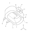
- FIG. 1 is a perspective view showing a configuration of an artificial hearing device 1 (hereinafter, may be simply referred to as “hearing device 1”) according to an embodiment.
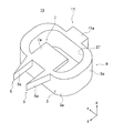
- FIG. 2 is a perspective view of the hearing aid 1 viewed from a direction different from that in FIG.
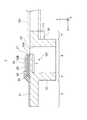
- FIG. 7 is a sectional view taken along line VII-VII in FIG.
- the hearing device 1 is placed in the cochlea that forms a part of the inner ear, and converts the sound waves in the cochlea into electric signals.
- the size of the hearing device 1 may be appropriately set so that it can be placed in the cochlea.
- the length of the hearing device 1 in the x direction, the length in the y direction, and the length in the z direction may be 0.1 mm or more and 3 mm or less.
- the hearing aid 1 includes, for example, a support portion 3, at least one (two in the illustrated example) electrode portions 5 protruding from the support portion 3 in a predetermined insertion direction (+y direction), and from the support portion 3. It has a vibrating portion 7 extending to the opposite side (-y side) from the insertion direction.
- the electrode portion 5 is a portion that is inserted into the inner wall of the cochlea in the +y direction, and at least the surface thereof has conductivity.
- the vibrating section 7 converts the sound wave into an electric signal and outputs the electric signal to the electrode section 5. As a result, an electric signal corresponding to the sound wave is applied to the auditory nerve from the electrode unit 5.
- the hearing aid 1 is fixed to the support portion 3 and surrounds the vibrating portion 7 with the support portion 3, and the vibrating portion 7 of the frame portion 9 is opposite to the insertion direction.
- the grip portion 11 extends from the portion located on the side ( ⁇ y side) to the ⁇ y side.
- the frame part 9 contributes to protecting the vibrating part 7 from unintended physical contact, for example.
- the grip portion 11 is a portion that is held by a device such as tweezers 101 (FIG. 7) when the hearing aid 1 is inserted, and contributes to facilitating the insertion.
- the hearing aid 1 has, for example, a base 13 made of an insulator or a semiconductor, and various thin films formed on the base 13.
- the base body 13 covers, for example, the support portion 3, the electrode portion 5, the vibrating portion 7, the frame portion 9 and the grip portion 11 described above, and constitutes these components. That is, the support portion 3, the electrode portion 5, the vibrating portion 7, the frame portion 9 and the grip portion 11 are integrally formed. And these parts have some or all of the thin film laminated
- Such a hearing aid 1 may be manufactured by a processing technique related to MEMS (Micro Electro Mechanical Systems), for example.
- FIG. 3 is a perspective view showing the base 13.
- 5 and 6 are perspective views showing the thin films formed on the substrate 13 in order from the substrate 13 side.
- FIGS. 3 to 6 are merely diagrams for explaining the configuration of the hearing aid 1, and are not diagrams showing an actual manufacturing process.
- various thin films are formed on the base body 13 having the same shape as the completed shape.
- part or all of the base body 13 is formed. The shape may be formed.
- the hearing aid 1 is, for example, a first conductor layer 15A (FIG. 4), a piezoelectric layer 17 (FIG. 5), and a second conductor layer 15B as a thin film overlying the base body 13 (FIG. 3) in order from the base body 13 side. (FIG. 6) and the insulator layer 19 (FIG. 1).
- the first conductor layer 15A and the second conductor layer 15B are simply referred to as "conductor layer 15", and the two may not be distinguished.
- the hearing aid 1 may include an insulator layer 20 (FIGS. 6 and 7) interposed between the first conductor layer 15A and the second conductor layer 15B.
- the piezoelectric layer 17 constitutes, for example, a part of the vibrating portion 7, and contributes to converting a sound wave into an electric signal.
- the two conductor layers 15 constitute, for example, a part of the vibrating portion 7 and the electrode portion 5, and contribute to taking out an electric signal from the piezoelectric layer 17 and transmitting the electric signal to the auditory nerve.
- the insulator layer 19 contributes to protection of the conductor layer 15, for example.
- each part of the base 13 that constitutes the support part 3, the electrode part 5, the vibrating part 7, the frame part 9 and the grip part 11 includes a support part base 3a, an electrode part base 5a, It may be conceptualized as the vibrating part base 7a, the frame part base 9a, and the grip part base 11a.
- the support portion 3 is a portion that supports the electrode portion 5 and the vibrating portion 7 as described above. Therefore, in the illustrated example, the support portion 3 includes at least a portion that extends over at least two electrode portions 5 and the vibrating portion 7 in the annular shape formed of the support portion 3 and the frame portion 9. In the description of the present embodiment, for convenience, a portion of the annular shape formed by the support portion 3 and the frame portion 9 that extends substantially in the x direction on the +y side will be described as the support portion 3.
- the shape and size of the support portion 3 may be set appropriately.
- the support portion 3 is configured in a wall shape (plate shape) facing the insertion direction (y direction).
- the support portion 3 has a shape in which the lengths in two directions (x direction and z direction) that intersect the insertion direction and are orthogonal to each other are longer than the length in the y direction.
- the support portion 3 may have a shape in which the length in the y direction is longer than the length in the x direction and/or the z direction. In the support portion 3, both the length in the x direction and the length in the z direction may be larger than the other.
- the wall-shaped support portion 3 may have a planar shape or a curved surface shape that bends in a plan view and/or a side view.
- the curved surface may be convex on either side of the insertion direction or the opposite side thereof, and may include an inflection point.
- the thickness of the wall-shaped supporting portion 3 (the length in the general y direction) may be constant or may vary.
- the support portion 3 is formed in a flat shape between the two electrode portions 5, and is formed in a curved surface shape that gradually recedes to the ⁇ y side outside the two electrode portions 5.
- the upper surface (the +z side surface) and the lower surface (the ⁇ z side surface) of the wall-shaped support portion 3 may be flat or curved. In the illustrated example, the upper surface and the lower surface are planes parallel to each other.
- the supporting part 3 also contributes to electrically connecting the electrode part 5 and the vibrating part 7, for example.
- the supporting portion 3 has a portion (wiring portion) of the conductor layer 15 extending from the vibrating portion 7 to the electrode portion 5.
- the supporting portion 3 also includes a part of the piezoelectric layer 17 in the illustrated example.
- the support portion 3 may not include a part of the piezoelectric layer 17.
- the conductor layer 15 is covered with the insulator layer 19. That is, the support portion 3 includes a part of the insulator layer 19.
- Electrode part For example, at least a part of the electrode part 5 on the tip side is thinner (pointed) toward the tip in a plan view and/or a side view. This facilitates insertion.
- the specific shape and dimensions (sharpness of the tip, etc.) of the shape that becomes thinner toward the tip may be appropriately set.
- the side surface (the surface facing the general x direction) or the upper and lower surfaces (the surface facing the z direction) with respect to the insertion direction may be flat (as shown in the drawing) or curved.
- the electrode portion 5 has a shape in which the whole is tapered toward the tip side in plan view. In a side view, the thickness (length in the z direction) of the electrode portion 5 is constant.
- the pair of electrode portions 5 has a flat shape in which side surfaces on the side between the pair of electrode portions 5 are parallel to each other.
- the side surface on the outer side of the pair of electrode portions 5 is an inclined surface that is located closer to the tip end side between the pair of electrode portions 5.
- the upper surface (the surface on the +z side) and the lower surface (the surface on the ⁇ z side) of the electrode portion 5 are flat surfaces parallel to the insertion direction (x direction).
- the relative sizes of the protruding length (y direction), the width (x direction) and the thickness (z direction) may be set appropriately.
- the protruding length is larger than the width and the thickness. This facilitates insertion.
- the thickness for example, maximum value
- the width for example, maximum value. This makes it possible to secure the strength of the electrode portion 5 while facilitating the insertion in the electrode portion 5 having a narrowed width and a tapered shape.
- Specific values of these dimensions may be appropriately set, and for example, the protruding length of the electrode portion 5 may be set to 0.2 mm or more and 1 mm or less.
- the relative sizes of the electrode part 5 and the support part 3 may be appropriately set.
- the thickness (z direction) of the electrode portion 5 is smaller than the length of the support portion 3 in the z direction.
- the length of the support portion 3 in the z direction may be 1.2 times or more, 1.5 times, or 2 times or more the thickness of the electrode portion 5.
- the position of the electrode portion 5 in the up-down direction (z direction) with respect to the support portion 3 is also appropriately set.
- the electrode portion 5 is located so as to be biased toward the upper surface side (+z side) with respect to the support portion 3. More specifically, the upper surface (the surface on the +z side) of the base body 13 is flush with the support portion 3 and the electrode portion 5.
- the electrode part 5 has a piercing electrode 21 formed by a part of the conductor layer 15. More specifically, one of the pair of electrode portions 5 (the electrode portion 5 on the +x side) is a piercing electrode 21 that is configured by a part of one of the two conductor layers 15 (first conductor layer 15A). And the other of the pair of electrode parts 5 (the electrode part 5 on the ⁇ x side) is formed by a part of the other of the two conductor layers 15 (second conductor layer 15B). It has an electrode 21.
- the relative position in the x direction between the puncture electrode 21 formed by the first conductor layer 15A and the puncture electrode 21 formed by the second conductor layer 15B may be opposite to the illustrated example.
- the piercing electrode 21 may be provided on any of the upper surface (+z side), the lower surface ( ⁇ z side) and the side surface (generally +x side and/or ⁇ x side) of the electrode section 5.
- the piercing electrode 21 may be provided on one of the various surfaces described above, may be provided on two or more surfaces, or may be provided partially on each surface. , May be entirely provided on each surface. In the illustrated example, the piercing electrode 21 is provided on the entire upper surface of the electrode portion 5.
- the vibrating portion 7 has an end portion on the inserting direction side as a fixed end fixed to the support portion 3, and an end portion on the opposite side to the inserting direction is a free end. That is, the vibrating portion 7 is supported by the supporting portion 3 in a cantilever shape.
- the vibrating portion 7 can be flexibly deformed in a direction (z direction) intersecting the insertion direction, and can be vibrated in the z direction.
- the vibrating portion 7 is formed, for example, in a plate shape facing the vibrating direction (z direction). In other words, in the vibrating portion 7, the length in the x direction and the length in the y direction are larger than the length (thickness) in the z direction. As a result, for example, the vibrating portion 7 is likely to vibrate in the z direction and is less likely to be flexibly deformed (vibrated) in the x direction.
- the shape and dimensions of the plate-shaped vibrating portion 7 may be set appropriately.
- the planar shape of the vibrating portion 7 may be appropriately set to a rectangular shape (illustrated example), a polygonal shape other than a rectangular shape, a circular shape, an elliptical shape, or the like.
- the rectangular shape or the polygonal shape mentioned here includes a rectangular shape or a polygonal shape in which the corners are chamfered, and the elliptical shape does not have to be an ellipse mathematically described. The same applies to other parts.
- the vibrating portion 7 may have a large length in either the x direction or the y direction.
- the thickness of the vibrating portion 7 (z direction) is smaller than the thickness of the electrode portion 5 (z direction) and the length of the support portion 3 in the z direction.
- the thickness of the vibrating portion 7 may be 1/2 or less or 1/3 or less of the thickness of the electrode portion 5, and/or 1/2 or less of the length of the supporting portion 3 in the z direction, 1 It may be /3 or less or 1/5 or less.
- the position of the vibrating portion 7 in the vertical direction (z direction) with respect to the supporting portion 3 may be set appropriately.
- the vibrating section 7 is located on the upper surface side (+z side) with respect to the supporting section 3. More specifically, the upper surface (the surface on the +z side) of the base body 13 is flush with the supporting portion 3 and the vibrating portion 7.
- the vibrating section 7 includes, for example, a lower electrode 23 (FIGS. 4 and 7) formed by a part of the first conductor layer 15A and an upper electrode 25 (FIG. 4A) formed by a part of the second conductor layer 15B. 6 and FIG. 7), a piezoelectric layer 17 (all or a part thereof) sandwiched between them, and a portion of the insulating layer 19 covering the upper electrode 25.
- the piezoelectric layer 17 has, for example, a polarization axis (electric axis or X axis in a single crystal) along its thickness direction (z direction). From another viewpoint, the piezoelectric layer 17 has a polarization axis along the facing direction of the lower electrode 23 and the upper electrode 25 and the vibration direction (z direction) of the vibrating portion 7.
- an electric signal (charge, voltage or current in another viewpoint) having a magnitude corresponding to the deformation amount of the flex deformation is extracted by the lower electrode 23 and the upper electrode 25. Be done.
- the electric signal is extracted as an AC signal having a frequency substantially equal to the vibration frequency.
- the shapes and sizes of the piezoelectric layer 17, the lower electrode 23, the upper electrode 25, and the insulating layer 19 may be set appropriately.
- these thin films extend over substantially the entire surface of the vibrating portion 7.
- the outer edge of the vibrating portion 7 and the outer edges of various thin films on the vibrating portion 7 may be aligned with each other or may be offset from each other.
- the frame portion 9 surrounds the vibrating portion 7 together with the support portion 3 as described above. More specifically, the support portion 3 and the frame portion 9 surround the vibrating portion 7 when viewed in the vibrating direction (z direction) of the vibrating portion 7. From another viewpoint, the support part 3 and the frame part 9 form a hole 27 in which the vibrating part 7 is accommodated, and the hole 27 penetrates in the z direction.
- the shapes of the rings of the support portion 3 and the frame portion 9 when viewed in the z direction may be any suitable shape.
- the shape may be rectangular, polygonal other than rectangular, circular, or elliptical.
- the shape of the inner edge and the shape of the outer edge of the ring may or may not be similar.
- the width of the ring (the distance from the inner edge to the outer edge of the ring) may or may not be constant.
- the shape of the ring is a rectangle in which the short side extends in the insertion direction (y direction) and the corners are relatively large and chamfered with curved lines.
- the width of the ring is set such that the size of the portion (short side) extending in the insertion direction is larger than the size of the portion (long side) extending in the direction orthogonal to the insertion direction.
- the shape and size of the frame portion 9 may be set appropriately.
- the frame portion 9 has a wall-like (plate-like) shape in which the thickness direction extends from the inside to the outside of the ring, like the support portion 3.
- the frame portion 9 has a shape in which the length of the vibrating portion 7 in the vibration direction (z direction) is longer than the length in the direction from the inner side to the outer side of the ring.
- the length of the frame portion 9 in the z direction is, for example, constant regardless of the position in the direction along the ring, and is equal to the length of the support portion 3 in the z direction. That is, the upper surface and the lower surface of the base body 13 are flush with each other across the support portion 3 and the frame portion 9.
- the frame 9 may not have a wall shape, but may have a shape in which the length from the inside to the outside of the ring is longer than the length in the z direction.
- the length of the frame portion 9 in the z direction may not be constant or may be different from the length of the support portion 3 in the z direction.
- the surface (top surface, inner peripheral surface, or outer peripheral surface) of the frame portion 9 may have irregularities.
- the frame portion 9 includes a part of the conductor layer 15 (poling pad 29 described later) and a part of the insulator layer 19.
- the polling pad 29 will be described later.
- the grip portion 11 is sandwiched by tweezers 101 in the vibration direction (z direction) of the vibration portion 7.
- the shape and the like of the grip portion 11 that basically assumes such a gripping direction will be exemplified.
- the grip portion 11 may be sandwiched in another direction (for example, the x direction).
- the shape and size of the grip portion 11 may be set appropriately.
- the grip portion 11 may have a large length in the x direction, a length in the y direction, or a length in the z direction.
- the general shape may be a rectangular parallelepiped shape, or may be a shape other than a rectangle in plan view and/or side view.
- the size relation between the grip 11 and the part of the hearing device 1 other than the grip 11 may be set appropriately.
- the grip portion 11 is a portion that can be regarded as extending from the frame portion 9 to the side ( ⁇ y side) opposite to the insertion direction, for example, the length of the grip portion 11 in the x direction is The length of the frame portion 9 in the x direction is shorter, and/or the length of the grip portion 11 in the z direction is shorter than the length of the frame portion 9 in the z direction (both are true in the illustrated example).
- the position of the grip portion 11 in the vertical direction (z direction) with respect to the frame portion 9 may be set appropriately.
- the grip portion 11 is located on the upper surface side (+z side) with respect to the frame portion 9. More specifically, the upper surface (the surface on the +z side) of the base body 13 is flush with the frame portion 9 and the grip portion 11.
- the base body 13 has a contact surface 10 (FIGS. 2 and 7) facing the ⁇ y side.
- the contact surface 10 is, for example, a portion with which the tip of the tweezers 101 contacts, and facilitates pressing the hearing device 1 in the insertion direction (+y direction) during insertion.
- the contact surface 10 is, for example, a surface orthogonal to the insertion direction and has a flat shape. However, for example, the contact surface 10 may be formed in a curved surface shape with the ⁇ y side being concave.
- the contact surface 10 may be regarded as a part of the frame portion 9, a part of the grip portion 11, or a separate portion from these.
- the contact surface 10 may be regarded as a portion different from the grip portion 11, and the expression may be made such that the contact surface 10 is adjacent to the grip portion 11. Further, in the description of the illustrated example, the contact surface 10 may be regarded as a part of the frame portion 9.
- the contact surface 10 may be smoothly (without a step) continuous with the surface on the ⁇ y side of the frame portion 9 as in the illustrated example, or unlike the illustrated example, it is continuous. You don't have to.
- the position of the contact surface 10 may be set appropriately. In the illustrated example, the contact surface 10 is adjacent to and below the grip portion 11. Then, only the lower tip of the pair of tips of the tweezers 101 contacts the contact surface 10. However, for example, the upper surface of the grip portion 11 may be lower than the upper surface of the frame portion 9 to form the contact surfaces 10 both above and below the grip portion 11, or only above the grip portion 11.
- the contact surface 10 may be formed. Further, unlike the illustrated example, in the aspect in which the tweezers 101 sandwich the grip portion 11 in the x direction, the contact surfaces 10 may be provided on both sides of the grip portion 11 in the x direction.
- the contact surface 10 (the position where the tip end of the tweezers 101 contacts) extends, for example, from the center of gravity G1 of the hearing device 1 (FIG. 7) to the side opposite to the direction of insertion (-y side) in parallel with the direction of insertion. It may be located on or near a virtual line (not shown). In this case, the probability that an unintended moment will occur when the contact surface 10 is pressed is reduced. That is, insertion is facilitated.
- the distance (shortest distance) between the contact surface 10 and the imaginary line may be, for example, 1 time or less or 1/2 or less of the thickness (z direction) of the electrode portion 5.
- the grip portion 11 has, for example, a concave groove 11r (FIG. 2 and FIG. 7) extending from the side opposite to the insertion direction ( ⁇ y side) to the contact surface 10 along the insertion direction (eg, in parallel). ing. This facilitates positioning of the tweezers 101 in the x direction, for example.
- the shape and size of the recessed groove 11r may be set appropriately.
- the concave groove 11r may extend in a constant cross-sectional shape parallel to the insertion direction, or may have a shape in which the width (x direction) increases toward the ⁇ y side.
- the shape of the base 13 is as described in the description of each part such as the support part 3, the electrode part 5 and the vibrating part 7.
- the base 13 is formed of, for example, an insulator or a semiconductor.
- the material of the base 13 may be an inorganic material or an organic material. Examples of the material of the base 13 include silicon, silicon oxide (SiO 2 ), silicon nitride (SiN), glass, ceramics, or resin.
- the base body 13 may be configured by stacking a plurality of layers made of different materials in the z direction.
- the base body 13 may be composed of a silicon layer and a SiO 2 layer overlapping the upper surface and/or the lower surface thereof.
- the shape of the conductor layer 15 is as described in the description of the support portion 3, the electrode portion 5, and the vibrating portion 7, except for the portion related to the poling pad 29 described later.
- the conductor layer 15 is made of metal, for example. Examples of the metal include gold (Au), platinum (Pt), aluminum (Al), copper (Cu), chromium (Cr), and alloys containing these.
- the thickness of the conductor layer 15 may be set appropriately.
- the piezoelectric layer 17 extends over substantially the entire vibrating portion 7, and the polarization direction (single crystal electric axis, X axis) is the same as the thickness direction (z direction) of the piezoelectric layer 17.
- the piezoelectric layer 17 may be made of a single crystal or a polycrystal. Examples of the material of the piezoelectric layer 17 include aluminum nitride (AlN), barium titanate (BTO:BaTiO 3 ), potassium sodium niobate (KNN:(K,Na)NbO 3 ), and bismuth sodium titanate (NBT:Na).
- the piezoelectric body may or may not be a ferroelectric body, and may or may not be a pyroelectric body. Further, the crystal structure may be an appropriate one such as perovskite type or wurtzite type. The thickness of the piezoelectric layer 17 may be set appropriately.
- the material of the insulating layers 19 and 20 may be an inorganic material or an organic material. Examples of the material of the insulator layers 19 and 20 include silicon oxide (SiO 2 ), glass, ceramics, and resin.
- the planar shape of the insulator layer 20 is not particularly illustrated, but may be an appropriate shape from the viewpoint of reducing the probability of a short circuit between the first conductor layer 15A and the second conductor layer 15B, for example.
- the two conductor layers 15 have a pair of poling pads.
- the pair of poling pads 29 are connected to the lower electrode 23 and the upper electrode 25. Therefore, by applying a voltage to the pair of poling pads 29, a voltage can be applied to the piezoelectric layer 17 in the vertical direction. As a result, for example, the polarization direction of the piezoelectric layer 17 disturbed by the process can be adjusted, and the piezoelectric layer 17 that has not been polarized can be polarized.
- the piezoelectric layer 17 may be formed so that the polarization direction is the z direction, and thereafter, the process of adjusting the polarization direction may not be performed. Further, for example, by applying a voltage to the pair of insertion electrodes 21, the polarization direction of the piezoelectric layer 17 disturbed by the process is adjusted, or the piezoelectric layer 17 that has not been polarized is polarized. You may.
- the polling pad 29 is provided on the frame portion 9, for example. Specifically, the polling pad 29 is located on the upper surface of the frame base 9a on both sides of the vibrating section 7 in the direction crossing the piercing direction (x direction).
- the width (the length from the inner edge to the outer edge) of both sides of the frame base body 9a in the x direction is, for example, the width of the electrode base body 5a (x direction) and/or the other portion of the frame base body 9a. Longer than width (length from inner edge to outer edge).
- the shape and size of the polling pad 29 may be set appropriately. In the illustrated example, the polling pad 29 has a rectangular shape.
- An example of the dimensions of the poling pad 29 is 150 ⁇ m or more ⁇ 150 ⁇ m or more.
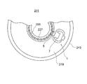
- FIG. 8 is a schematic diagram showing a cross section of the cochlear canal 213 of the cochlea 211.
- the cross section here is a cross section orthogonal to the direction in which the cochlear canal 213 extends spirally.
- FIG. 9 is a sectional view taken along line IX-IX in FIG.
- the inside of the cochlear canal 213 is divided into a front floor 215, a central floor 217 and a tympanic floor 219. These cavities are filled with lymph.
- the central floor 217 and the tympanic floor 219 are separated by the basement membrane 221.
- the basement membrane 221 vibrates due to the sound wave transmitted through the lymph. This vibration is converted into an electric signal by the Corti device 223 located in the central floor 217, and is transmitted to the auditory nerve 225 (the spiral ganglion), and further to the brain.
- the auditory nerve 225 is located in the bone spiral plate 227 that constitutes the inner wall of the spiral of the cochlear canal 213.
- the hearing aid 1 is arranged, for example, in the tympanic floor 219. More specifically, the electrode portion 5 is inserted into the bone spiral plate 227 so that the upper surface of the vibrating portion 7 faces the basement membrane 221 with an appropriate gap. At the time of insertion, for example, as described with reference to FIG. 7, the grasping portion 11 is grasped by the tweezers 101 and the contact surface 10 is pushed by the tip of the tweezers 101. The electrode part 5 is inserted into the bone spiral plate 227, for example, to its root or its vicinity. The detachment of the electrode portion 5 from the bone spiral plate 227 is suppressed by, for example, the sliding resistance obtained from the contact pressure between the both. The puncture electrode 21 of the electrode unit 5 contacts, for example, the auditory nerve 225. After the insertion, the grip 11 may be left on the scala 219 as it is or may be removed from the hearing device 1.
- the vibration of the basement membrane 221 is transmitted to the vibrating section 7 via the lymph and the vibrating section 7 vibrates.
- the vibrating unit 7 vibrates by transmitting a sound wave to the vibrating unit 7 via lymphatic fluid without passing through the basement membrane 221.
- the vibration of the vibrating portion 7 is converted into an electric signal by the piezoelectric layer 17 and output to the insertion electrode 21. As a result, the electric signal is transmitted to the auditory nerve 225.
- an electric signal having a positive potential with respect to a predetermined potential has the same action as the electric signal transmitted from the Corti device 223 to the auditory nerve 225.
- the vibrating unit 7 vibrates to both the +z side and the ⁇ z side with respect to the initial position, so that an electric signal having a positive potential is alternately output to the pair of electrode units 5. Therefore, since the hearing aid 1 has the pair of electrode portions 5, basically, the same action as an electric signal transmitted from the Corti device 223 to the auditory nerve 225 is performed over the entire period of each sound wave. An electrical signal is applied to the auditory nerve 225.
- the hearing device 1 may have only one electrode unit 5. In this case, the hearing aid 1 basically applies to the auditory nerve 225 an electric signal having the same action as the electric signal transmitted from the Corti device 223 to the auditory nerve 225 over half of each cycle of the sound wave.
- Only one hearing device 1 may be provided in the cochlea 211, or a plurality of hearing devices 1 may be provided along the spiral of the cochlea 213. Further, the position of the hearing aid 1 in the direction along the spiral may be appropriately set.
- the cochlear duct 213 corresponds to a high frequency sound wave on the side closer to the middle ear and a lower frequency sound wave on the side farther from the middle ear. Therefore, an appropriate number of the hearing aids 1 may be provided at the position or range within the cochlear canal 213 according to the frequency that is difficult for the patient to hear.
- the vibrating section 7 of the hearing device 1 may have a natural frequency set so that resonance easily occurs at a frequency corresponding to the position where the vibration section 7 is provided.
- the piercing-type piezoelectric device (the artificial hearing device 1 arranged in the cochlea) has the support portion 3, the electrode portion 5, the vibrating portion 7, and the frame portion 9.
- the electrode portion 5 projects from the support portion 3 in a predetermined insertion direction (+y direction).
- the vibrating portion 7 extends from the support portion 3 to the side ( ⁇ y side) opposite to the insertion direction, can vibrate in the vibration direction (z direction) intersecting the insertion direction, and vibrates in the vibration direction. Can be converted into an electric signal and output to the electrode unit 5.
- the frame portion 9 is fixed to the support portion 3 and surrounds the vibrating portion 7 when viewed in the vibrating direction.
- the hearing aid 1 can be placed at any position (here, inside the cochlea), and the handleability of the hearing aid 1 is improved.
- the vibrating portion 7 is surrounded by the support portion 3 and the frame portion 9, the probability of damaging the vibrating portion 7 due to unintentional contact with the vibrating portion 7 is reduced. This further improves the handleability.
- the strength of the vibrating portion 7 can be reduced, the vibrating portion 7 can be made thin so as to easily vibrate and the sensitivity can be improved.
- the support portion 3 and the frame portion 9 can reduce the influence of sound waves from a direction intersecting the vibration direction of the vibrating portion 7 on the vibration of the vibrating portion 7. As a result, it is possible to strengthen the directivity with respect to the reception of the sound wave of the hearing device 1.
- the thickness of the support portion 3 and the frame portion 9 in the vibration direction (z direction) is thicker than the thickness of the vibration portion 7 in the vibration direction.
- a human body or an instrument is less likely to come into contact with the vibrating section 7, so that the function of protecting the vibrating section 7 by the support section 3 and the frame section 9 is improved.
- the function of protecting the vibrating portion 7 is improved also from this viewpoint.
- the effect of reducing the influence of the sound waves from the direction intersecting the vibration direction of the vibrating section 7 on the vibration of the vibrating section 7 is also improved.
- the support portion 3 and the frame portion 9 form a hole 27 that penetrates in the vibration direction (z direction).
- the vibrating portion 7 is located at one end (end on the +z side) of the hole 27 in the vibrating direction.
- the vibrating unit 7 is more likely to receive the sound wave from the +z side, while the protection from the ⁇ z side is strengthened.
- the vibrating portion 7 can be arranged close to the basement membrane 221 while the protection of the vibrating portion 7 can be strengthened.
- the conductor layer 15 is less likely to be disconnected.
- the hearing aid 1 extends from the portion of the frame portion 9 located on the opposite side ( ⁇ y side) of the vibrating portion 7 to the inserting direction to the opposite side of the inserting direction. It further has the holding part 11 which is.
- the grip portion 11 can be gripped by an instrument such as tweezers 101, and the handleability of the hearing aid 1 is further improved.
- the hearing aid 1 has the contact surface 10 that is adjacent to the grip portion 11 and faces the side opposite to the insertion direction.
- the abutting surface 10 can be pushed in the insertion direction by an instrument (tweezers 101) that holds the holding portion 11. That is, the work of inserting is facilitated (the handleability of the hearing aid 1 is improved).
- the contact surface 10 is orthogonal to the insertion direction and/or when the contact surface 10 and the center of gravity G1 are within a predetermined distance when viewed in the insertion direction, The work is further facilitated.
- the grip portion 11 has the concave groove 11r extending from the side opposite to the insertion direction to the contact surface 10.
- an instrument (tweezers 101) for gripping the grip 11 can be positioned in a direction (x direction) intersecting the insertion direction, and the tweezers 101 grips the grip 11 when pressing for insertion.
- the probability of slipping in the x direction can be reduced. That is, the work of inserting is facilitated.
- the tip of the tweezers 101 can be guided in the process of moving the tweezers 101 in the insertion direction, the tip of the tweezers 101 can be moved so as to reduce the displacement in the x direction between the center of gravity G1 and the tip of the tweezers 101. The contact with the contact surface 10 is facilitated.
- the vibrating section 7 is sandwiched between a pair of counter electrodes (lower electrode 23 and upper electrode 25) facing each other in the vibrating direction (z direction) and these electrodes (23 and 25).
- the piezoelectric layer 17 has a polarization direction in the z direction.
- the frame portion 9 has a pair of poling pads 29 connected to the lower electrode 23 and the upper electrode 25.
- the frame part 9 functions not only as a part for mechanically protecting the vibrating part 7, but also as a part for arranging the polling pad 29.
- the width (x direction) of the electrode portion 5 is narrowed for insertion, it is difficult to widen the width of the insertion electrode 21.
- the frame portion 9 since the frame portion 9 is not a portion to be inserted, it is easy to increase the width from the inner edge to the outer edge to widen the width of the polling pad 29. That is, the width of the poling pad 29 can be made larger than the width of the electrode portion 5.
- the pin can be brought into contact with the poling pad 29 more easily than the voltage application pin is brought into contact with the electrode portion 5. That is, the polarization process can be facilitated.
- the hearing aid 1 has a plurality of electrode portions 5 protruding from the support portion 3 in the insertion direction.
- the hearing device 1 it is possible to reduce the probability that the hearing device 1 will fall off, for example, as compared with the case where there is one electrode unit 5. Further, as described above, when the number of the electrode portions 5 is one, an electric signal having the same action as the electric signal transmitted from the Corti device 223 to the auditory nerve 225 is given from the electrode portion 5 to the auditory nerve 225 every half cycle. However, in the case of more than one, they are continuously given.
- the plurality of electrode portions 5 include a pair of electrode portions 5 adjacent to each other. Side surfaces of the pair of electrode portions 5 on the side between the pair of electrode portions 5 are parallel to each other.
- the insertion is easy. More specifically, for example, in the case where two side surfaces on the side between the pair of electrode portions 5 are closer to each other toward the tip side (also in this case, the technology according to the present disclosure), one pair. The inclination angles of the two side surfaces on the outer side of the electrode portion 5 with respect to the insertion direction are likely to be large. As a result, the force exerted by the bone spiral plate on the two outer side surfaces is increased against the force in the insertion direction. In addition, for example, when the two side surfaces on the side between the pair of electrode portions 5 are separated from each other toward the tip side (also in this case, the technology according to the present disclosure is included), one of the bone spiral plates is used.
- a compressive force in the direction between the pair of electrode portions 5 is applied to the portion located between the pair of electrode portions 5 with the insertion.
- the force that the electrode portion 5 receives from the bone spiral plate against the force in the insertion direction tends to increase.
- the two side surfaces on the side between the pair of electrode portions 5 are parallel to each other, the probability that the above-described inconvenience will occur is reduced.
- the thickness of the vibrating portion 7 in the vibration direction (z direction) is smaller than the thickness of the electrode portion 5 in the z direction.
- the strength of the electrode unit 5 is improved, and by extension, the strength of fixing the hearing device 1 due to the electrode unit 5 being inserted into the inner wall of the cochlea 211 is improved.
- the vibrating section 7 can be easily vibrated, and the sensitivity of the hearing aid 1 can be improved.
- the artificial hearing device 1 is an example of a piercing-type piezoelectric device.
- the lower electrode 23 and the upper electrode 25 are an example of a pair of counter electrodes.
- the polling pad 29 is an example of a pad.
- a piercing-type piezoelectric device does not vibrate due to a sound wave that reaches the vibrating section, but the vibrating section vibrates when an object into which the piercing-type piezoelectric device is inserted operates or vibrates. May be.
- the piercing-type piezoelectric device may be used for the purpose of detecting the magnitude of impact, not for detecting the frequency and amplitude of vibration.
- the piercing-type piezoelectric device may be pierced into a body other than the inner wall of the cochlea when piercing into a human body.
- the piercing piezoelectric device when used for the purpose of outputting a signal according to the frequency and amplitude of a sound wave, the sound wave is received not through the liquid (lymph) but through the gas (for example, air). You may.
- the size of the piercing-type piezoelectric device may be appropriately set according to the various uses mentioned above.
- the support part and the frame part may surround two or more vibration parts instead of surrounding one vibration part.
- one piercing piezoelectric device may include two or more vibrating parts.
- the two or more vibrating sections may output electrical signals to different electrode sections, for example.
- the frame portion may be directly held by an appropriate device.
- the holding method is not limited to gripping and may be suction or the like.
- the grip may not have the groove 11r that guides the device to the contact surface 10.
- the polling pad 29 may not be provided.
- the insulator layer 20 can be omitted depending on the planar shapes of the two conductor layers and the piezoelectric layer. Conversely, members not shown in the embodiments may be added.
- Various parts such as the supporting part, the electrode part, the vibrating part and the frame part may not share the integrally formed base. For example, they may be made separately and fixed to each other. In addition, for example, the entire electrode portion may be made of a conductive member.
- the support part and the frame part may not be thicker than the electrode part and/or the vibration part in the vibration direction of the vibration part. For example, even if the frame portion is relatively thin, the probability that a human body or a device directly contacts the vibrating portion is reduced. Further, the support portion and the frame portion do not have to form a hole through which the vibration portion penetrates in the vibration direction. Depending on the application of the piercing-type piezoelectric device, one or both of the holes may be closed.
- the vibrating portion may be located at any position in the hole penetrating direction with respect to the hole, for example, may be located near the center in the penetrating direction.
Landscapes
- Health & Medical Sciences (AREA)
- Life Sciences & Earth Sciences (AREA)
- Biomedical Technology (AREA)
- Acoustics & Sound (AREA)
- Biophysics (AREA)
- Otolaryngology (AREA)
- Psychology (AREA)
- Engineering & Computer Science (AREA)
- Physics & Mathematics (AREA)
- Heart & Thoracic Surgery (AREA)
- Vascular Medicine (AREA)
- Animal Behavior & Ethology (AREA)
- General Health & Medical Sciences (AREA)
- Public Health (AREA)
- Veterinary Medicine (AREA)
- Electrotherapy Devices (AREA)
- Piezo-Electric Transducers For Audible Bands (AREA)
Abstract
蝸牛内に配置される人工聴覚器は、支持部、電極部、振動部及び枠部を有している。電極部は、支持部から所定の刺入方向へ突出している。振動部は、支持部から刺入方向とは反対側へ延び出ており、刺入方向に交差する振動方向に振動可能であるとともに前記振動方向の振動を電気信号に変換して電極部に出力可能である。枠部は、支持部に固定されているとともに振動方向に見て振動部を囲んでいる。
Description
本開示は、人工聴覚器及び刺入型圧電デバイスに関する。
人工聴覚器として、内耳の一部を構成する蝸牛内に配置されるものが提案されている(例えば特許文献1)。この人工聴覚器は、蝸牛内に到達した音波を電気信号に変換する。電気信号はラセン神経節細胞に電気刺激として与えられる。
本開示の一態様に係る、蝸牛内に配置される人工聴覚器は、支持部と、電極部と、振動部と、枠部とを有している。前記電極部は、前記支持部から所定の刺入方向へ突出しているとともに少なくとも表面に導電性を有しており、前記蝸牛の内壁に刺入される。前記振動部は、前記支持部から前記刺入方向とは反対側へ延び出ており、前記蝸牛内の音波によって前記刺入方向に交差する振動方向に振動可能であるとともに前記振動方向の振動を電気信号に変換して前記電極部に出力可能である。前記枠部は、前記支持部に固定されているとともに前記振動方向に見て前記振動部を囲んでいる。
本開示の一態様に係る刺入型圧電デバイスは、支持部と、電極部と、振動部と、枠部とを有している。前記電極部は、前記支持部から所定の刺入方向へ突出しているとともに少なくとも表面に導電性を有している。前記振動部は、前記支持部から前記刺入方向とは反対側へ延び出ており、前記刺入方向に交差する振動方向に振動可能であるとともに前記振動方向の振動を電気信号に変換して前記電極部に出力可能である。前記枠部は、前記支持部に固定されており、前記振動方向に見て前記振動部を囲んでいる。
以下、図面を参照して本開示に係る実施形態について説明する。以下の図面は、模式的なものである。従って、細部は省略されることがあり、また、寸法比率等は現実のものと必ずしも一致しない。また、複数の図面相互の寸法比率も必ずしも一致しない。
各図には、説明の便宜のために、直交座標系xyzを付すことがある。人工聴覚器は、いずれの方向が上方又は下方として使用されてもよいものであるが、以下では、便宜上、z方向の正側を上方として、上面又は下面等の用語を用いることがある。また、平面視という場合、特に断りがない限り、z方向に見ることをいうものとする。側面視という場合、特に断りがない限り、x方向に見ることをいうものとする。
(人工聴覚器の概要)
図1は、実施形態に係る人工聴覚器1(以下、単に「聴覚器1」ということがある。)の構成を示す斜視図である。図2は、図1とは異なる方向から聴覚器1を見た斜視図である。図7は、図1のVII-VII線における断面図である。
図1は、実施形態に係る人工聴覚器1(以下、単に「聴覚器1」ということがある。)の構成を示す斜視図である。図2は、図1とは異なる方向から聴覚器1を見た斜視図である。図7は、図1のVII-VII線における断面図である。
聴覚器1は、内耳の一部を構成する蝸牛内に配置され、蝸牛内の音波を電気信号に変換する。聴覚器1の大きさは、蝸牛内に配置可能に適宜に設定されてよい。一例を挙げると、聴覚器1のx方向の長さ、y方向の長さ及びz方向の長さそれぞれは、0.1mm以上3mm以下とされてよい。
聴覚器1は、例えば、支持部3と、支持部3から所定の刺入方向(+y方向)へ突出している少なくとも1つ(図示の例では2つ)の電極部5と、支持部3から前記の刺入方向とは反対側(-y側)へ延び出ている振動部7とを有している。電極部5は、蝸牛の内壁に+y方向へ刺入される部分であり、少なくとも表面に導電性を有している。振動部7は音波を電気信号に変換して電極部5に出力する。これにより、音波に応じた電気信号が電極部5から聴神経に付与される。
また、聴覚器1は、支持部3に固定されているとともに支持部3とで振動部7を囲んでいる枠部9と、枠部9のうち振動部7に対して刺入方向とは反対側(-y側)に位置する部分から-y側へ延び出ている把持部11とを有している。枠部9は、例えば、意図していない物理的な接触から振動部7を保護することに寄与している。把持部11は、例えば、聴覚器1を刺入するときにピンセット101(図7)等の器具に保持される部分であり、刺入の容易化に寄与している。
また、別の観点では、聴覚器1は、例えば、絶縁体又は半導体からなる基体13と、基体13に成膜された種々の薄膜とを有している。基体13は、例えば、上述した支持部3、電極部5、振動部7、枠部9及び把持部11に亘っており、これらを構成している。すなわち、支持部3、電極部5、振動部7、枠部9及び把持部11は一体的に形成されている。そして、これらの部位は、必要に応じて基体13に重ねられた薄膜の一部又は全部を有している。このような聴覚器1は、例えば、MEMS(Micro Electro Mechanical Systems)に関する加工技術によって作製されてよい。
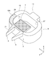
図3は、基体13を示す斜視図である。図4、図5及び図6は、基体13に成膜されている薄膜を基体13側のものから順に示す斜視図である。ただし、図3~図6は、あくまで聴覚器1の構成を説明するための図であって、実際の作製過程を示している図ではない。例えば、図3~図6では、完成後の形状と同じ形状の基体13に対して種々の薄膜が形成されているが、少なくとも1つの薄膜となる材料の成膜後に基体13の一部又は全部の形状が形成されてもよい。
聴覚器1は、例えば、基体13(図3)の上に重なる薄膜として、基体13側から順に、第1導体層15A(図4)、圧電体層17(図5)、第2導体層15B(図6)及び絶縁体層19(図1)を有している。以下の説明では、第1導体層15A及び第2導体層15Bを単に「導体層15」といい、両者を区別しないことがある。この他、聴覚器1は、第1導体層15A及び第2導体層15Bの間に介在する絶縁体層20(図6及び図7)を有していてもよい。
圧電体層17は、例えば、振動部7の一部を構成しており、音波を電気信号に変換することに寄与している。2つの導体層15は、例えば、振動部7及び電極部5の一部を構成しており、圧電体層17から電気信号を取り出し、その電気信号を聴神経に伝えることに寄与している。絶縁体層19は、例えば、導体層15の保護に寄与している。
導体層15、圧電体層17及び絶縁体層19の厚さは、例えば、基体13が成す形状の凹凸に比較して小さい。従って、以下において、支持部3、電極部5、振動部7、枠部9及び把持部11の形状及び大きさに関する説明は、特に断りが無い限り、基体13の形状の説明と捉えられてよい。図3に符号を付すように、基体13のうち、支持部3、電極部5、振動部7、枠部9及び把持部11を構成する各部分は、支持部基体3a、電極部基体5a、振動部基体7a、枠部基体9a及び把持部基体11aと概念されてよい。
(支持部)
支持部3と枠部9とは繋がっており、両者は明瞭に区別可能である必要は無い。支持部3は、上記のように電極部5及び振動部7を支持している部分である。従って、図示の例では、支持部3は、支持部3及び枠部9からなる環状の形状のうち、少なくとも、2つの電極部5及び振動部7に亘る部分を含んでいる。本実施形態の説明では、便宜上、支持部3及び枠部9がなす環状の形状のうち、+y側において概ねx方向に延びている部分を支持部3と捉えて説明する。
支持部3と枠部9とは繋がっており、両者は明瞭に区別可能である必要は無い。支持部3は、上記のように電極部5及び振動部7を支持している部分である。従って、図示の例では、支持部3は、支持部3及び枠部9からなる環状の形状のうち、少なくとも、2つの電極部5及び振動部7に亘る部分を含んでいる。本実施形態の説明では、便宜上、支持部3及び枠部9がなす環状の形状のうち、+y側において概ねx方向に延びている部分を支持部3と捉えて説明する。
支持部3の形状及び大きさは適宜に設定されてよい。図示の例では、支持部3は、刺入方向(y方向)に面する壁状(板状)に構成されている。換言すれば、支持部3は、刺入方向に交差するとともに互いに直交する2方向(x方向及びz方向)の長さが、y方向の長さよりも長い形状である。ただし、支持部3は、y方向の長さがx方向及び/又はz方向の長さより長い形状であっても構わない。支持部3において、x方向の長さ及びz方向の長さは、いずれが他方よりも大きくても構わない。
壁状の支持部3は、平面状であってもよいし、平面視及び/又は側面視において曲がる曲面状であってもよい。曲面は、刺入方向及びその反対側のいずれ側を凸としていてもよいし、変曲点を含んでいてもよい。壁状の支持部3の厚さ(概略y方向の長さ)は、一定であってもよいし、変化していてもよい。図示の例では、支持部3は、2つの電極部5の間においては平面状に形成されており、2つの電極部5の外側においては徐々に-y側へ後退する曲面状に形成されている。また、壁状の支持部3の上面(+z側の面)及び下面(-z側の面)は、平面状であってもよいし、曲面状であってもよい。図示の例では、上面及び下面は互いに平行な平面状である。
支持部3は、例えば、電極部5と振動部7とを電気的に接続することにも寄与している。具体的には、図4及び図6に示すように、支持部3は、導体層15のうちの振動部7から電極部5へ延びる部分(配線部)を有している。支持部3は、図示の例では、圧電体層17の一部も含んでいる。ただし、支持部3は、圧電体層17の一部を含んでいなくてもよい。また、支持部3において、導体層15は絶縁体層19によって覆われている。すなわち、支持部3は、絶縁体層19の一部を含んでいる。
(電極部)
電極部5は、例えば、少なくとも先端側の一部が、平面視及び/又は側面視において先端ほど細くなっている(尖っている)。これにより、刺入が容易化される。先端ほど細くなる形状の具体的な形状及び寸法(先端の鋭さ等)は適宜に設定されてよい。刺入方向に対する側面(概略x方向に面する面)又は上下面(z方向に面する面)は、平面状であってもよいし(図示の例)、曲面状であってもよい。
電極部5は、例えば、少なくとも先端側の一部が、平面視及び/又は側面視において先端ほど細くなっている(尖っている)。これにより、刺入が容易化される。先端ほど細くなる形状の具体的な形状及び寸法(先端の鋭さ等)は適宜に設定されてよい。刺入方向に対する側面(概略x方向に面する面)又は上下面(z方向に面する面)は、平面状であってもよいし(図示の例)、曲面状であってもよい。
図示の例では、電極部5は、平面視においてその全体が先端側ほど細くなる形状である。側面視においては、電極部5の厚さ(z方向の長さ)は一定とされている。また、1対の電極部5は、当該1対の電極部5の間となる側の側面が互いに平行な平面状とされている。1対の電極部5の外側となる側の側面は、先端側ほど1対の電極部5の間となる側へ位置する傾斜面となっている。電極部5の上面(+z側の面)及び下面(-z側の面)は刺入方向(x方向)に平行な平面状となっている。
電極部5において、突出長さ(y方向)、幅(x方向)及び厚さ(z方向)の相対的な大きさは適宜に設定されてよい。例えば、突出長さは、幅及び厚さよりも大きい。これにより、刺入が容易化されている。また、例えば、厚さ(例えば最大値)は幅(例えば最大値)よりも大きい。これにより、幅を狭くして先細り形状とされている電極部5において、刺入を容易化しつつ電極部5の強度を確保することができる。これらの寸法の具体的な値も適宜に設定されてよく、例えば、電極部5の突出長さは0.2mm以上1mm以下とされてよい。
電極部5及び支持部3の相対的な大きさ等も適宜に設定されてよい。図示の例では、電極部5の厚さ(z方向)は、支持部3のz方向の長さよりも小さくされている。例えば、支持部3のz方向の長さは、電極部5の厚さの1.2倍以上、1.5倍又は2倍以上とされてよい。
また、このように電極部5の厚さが支持部3のz方向の長さに対して小さい場合において、電極部5の支持部3に対する上下方向(z方向)の位置も適宜に設定されてよい。例えば、電極部5は、支持部3に対して上面側(+z側)に偏って位置している。より詳細には、基体13の上面(+z側の面)は、支持部3から電極部5に亘って面一である。
電極部5は、導体層15の一部によって構成されている刺入電極21を有している。より詳細には、1対の電極部5のうち一方(+x側の電極部5)は、2つの導体層15の一方(第1導体層15A)の一部によって構成されている刺入電極21を有しており、1対の電極部5のうち他方(-x側の電極部5)は、2つの導体層15の他方(第2導体層15B)の一部によって構成されている刺入電極21を有している。なお、第1導体層15Aが構成する刺入電極21と第2導体層15Bが構成する刺入電極21とのx方向の相対位置は、図示の例とは逆であってもよい。
刺入電極21は、電極部5の上面(+z側)、下面(-z側)及び側面(概ね+x側及び/又は-x側)のいずれに設けられてもよい。また、刺入電極21は、上記の種々の面のうち1つの面に設けられてもよいし、2以上の面に設けられてもよいし、各面において一部に設けられてもよいし、各面において全体に設けられてもよい。図示の例では、刺入電極21は、電極部5の上面の全体に設けられている。
(振動部)
振動部7は、刺入方向側の端部が支持部3に固定される固定端とされ、刺入方向とは反対側の端部が自由端とされている。すなわち、振動部7は、片持ち梁状に支持部3に支持されている。振動部7は、刺入方向に交差する方向(z方向)に撓み変形可能であり、ひいては、z方向に振動可能である。振動部7は、例えば、振動方向(z方向)に面する板状に形成されている。換言すれば、振動部7においては、z方向の長さ(厚さ)に対してx方向の長さ及びy方向の長さが大きい。これにより、例えば、振動部7は、z方向に振動しやすくなっているとともに、x方向への撓み変形(振動)が生じにくくなっている。
振動部7は、刺入方向側の端部が支持部3に固定される固定端とされ、刺入方向とは反対側の端部が自由端とされている。すなわち、振動部7は、片持ち梁状に支持部3に支持されている。振動部7は、刺入方向に交差する方向(z方向)に撓み変形可能であり、ひいては、z方向に振動可能である。振動部7は、例えば、振動方向(z方向)に面する板状に形成されている。換言すれば、振動部7においては、z方向の長さ(厚さ)に対してx方向の長さ及びy方向の長さが大きい。これにより、例えば、振動部7は、z方向に振動しやすくなっているとともに、x方向への撓み変形(振動)が生じにくくなっている。
板状の振動部7の形状及び寸法等は適宜に設定されてよい。例えば、振動部7の平面形状は、矩形状(図示の例)、矩形以外の多角形状、円形状、楕円状など、適宜に設定されてよい。ここでいう矩形状又は多角形状は、矩形又は多角形において角部が面取りされたものを含み、楕円状は数学で言う楕円でなくてよい。これらのことは、他の部位に関しても同様である。振動部7は、x方向の長さとy方向の長さとのいずれが大きくてもよい。振動部7の各種の寸法と、電極部5及び支持部3の各種の寸法との間の大小関係も適宜に設定されてよい。図示の例では、振動部7の厚さ(z方向)は、電極部5の厚さ(z方向)及び支持部3のz方向の長さよりも小さくされている。例えば、振動部7の厚さは、電極部5の厚さの1/2以下又は1/3以下とされてよく、及び/又は支持部3のz方向の長さの1/2以下、1/3以下又は1/5以下とされてよい。
このように振動部7の厚さが支持部3のz方向の長さよりも小さい場合において、振動部7の支持部3に対する上下方向(z方向)の位置は適宜に設定されてよい。図示の例では、振動部7は、支持部3に対して上面側(+z側)に偏って位置している。より詳細には、基体13の上面(+z側の面)は、支持部3から振動部7に亘って面一である。
振動部7は、例えば、第1導体層15Aの一部によって構成されている下部電極23(図4及び図7)と、第2導体層15Bの一部によって構成されている上部電極25(図6及び図7)と、これらの間に挟まれている圧電体層17(その全部又は一部)と、絶縁体層19のうち上部電極25を覆っている部分とを有している。圧電体層17は、例えば、その厚さ方向(z方向)に沿って分極軸(単結晶においては電気軸又はX軸)を有している。別の観点では、圧電体層17は、下部電極23及び上部電極25の対向方向及び振動部7の振動方向(z方向)に沿って分極軸を有している。
従って、圧電体層17がz方向に撓み変形すると、その撓み変形の変形量に応じた大きさの電気信号(別の観点では、電荷、電圧又は電流)が下部電極23及び上部電極25によって取り出される。また、圧電体層17がz方向の撓み変形による振動を生じると、電気信号は振動の周波数と概ね同等の周波数を有する交流信号として取り出される。
振動部7において、圧電体層17、下部電極23、上部電極25及び絶縁体層19の形状及び大きさは適宜に設定されてよい。図示の例では、これらの薄膜は、振動部7の概ね全面に亘って広がっている。平面視において、振動部7の外縁及び振動部7上の種々の薄膜の外縁は、互いに一致していてもよいし、互いにずれていてもよい。
(枠部)
枠部9は、既述のように、支持部3とで振動部7を囲んでいる。より具体的には、支持部3及び枠部9は、振動部7の振動方向(z方向)に見て振動部7を囲んでいる。別の観点では、支持部3及び枠部9は、振動部7が収容される孔27を構成しており、孔27は、z方向に貫通している。
枠部9は、既述のように、支持部3とで振動部7を囲んでいる。より具体的には、支持部3及び枠部9は、振動部7の振動方向(z方向)に見て振動部7を囲んでいる。別の観点では、支持部3及び枠部9は、振動部7が収容される孔27を構成しており、孔27は、z方向に貫通している。
z方向に見た支持部3及び枠部9の環の形状は適宜な形状とされてよい。例えば、当該形状は、矩形状、矩形以外の多角形状、円形状又は楕円状とされてよい。また、環の内縁の形状と外縁の形状とは、相似形であってもよいし、相似形でなくてもよい。環の幅(環の内縁から外縁までの距離)は一定であってもよいし、一定でなくてもよい。
図示の例では、環の形状は、刺入方向(y方向)を短辺が延びる方向とする矩形において角部を曲線によって比較的大きく面取りした形状とされている。また、環の幅は、刺入方向に延びる部分(短辺)における大きさが、刺入方向に直交する方向に延びる部分(長辺)における大きさよりも大きくされている。
枠部9の形状及び大きさは適宜に設定されてよい。図示の例では、枠部9は、支持部3と同様に、上記環の内側から外側への方向を厚さ方向とする壁状(板状)とされている。換言すれば、枠部9は、振動部7の振動方向(z方向)の長さが環の内側から外側への方向の長さよりも長い形状である。また、枠部9のz方向の長さは、例えば、環に沿う方向の位置によらずに一定とされているとともに、支持部3のz方向の長さと同等とされている。すなわち、基体13の上面及び下面それぞれは、支持部3及び枠部9に亘って面一である。
ただし、枠部9は、壁状ではなく、環の内側から外側への方向の長さがz方向の長さよりも長い形状であっても構わない。枠部9のz方向の長さは、一定でなくてもよいし、支持部3のz方向の長さと異なっていてもよい。枠部9の表面(上面、内周面又は外周面)には凹凸があっても構わない。
図示の例では、枠部9は、導体層15の一部(後述するポーリングパッド29等)及び絶縁体層19の一部を有している。ポーリングパッド29については後述する。
(把持部及び当接面)
把持部11は、図7では、ピンセット101によって振動部7の振動方向(z方向)において挟まれている。以下の説明では、基本的に、このような把持の方向を前提とした把持部11の形状等を例示する。ただし、把持部11は、他の方向(例えばx方向)において挟まれるものとされても構わない。
把持部11は、図7では、ピンセット101によって振動部7の振動方向(z方向)において挟まれている。以下の説明では、基本的に、このような把持の方向を前提とした把持部11の形状等を例示する。ただし、把持部11は、他の方向(例えばx方向)において挟まれるものとされても構わない。
把持部11の形状及び大きさは適宜に設定されてよい。例えば、把持部11は、x方向の長さ、y方向の長さ及びz方向の長さのいずれが大きくてもよい。概略形状は、直方体状であってもよいし、平面視及び/又は側面視において矩形以外の形状とされていてもよい。
把持部11と、聴覚器1の把持部11以外の部分との大小関係も適宜に設定されてよい。ただし、把持部11は、枠部9から刺入方向とは反対側(-y側)へ延び出ていると捉えることができる部分であるから、例えば、把持部11のx方向の長さは枠部9のx方向の長さよりも短い、及び/又は把持部11のz方向の長さは枠部9のz方向の長さよりも短い(図示の例では双方が成り立つ。)。
把持部11の厚さ(z方向)が枠部9のz方向の長さよりも小さい場合において、把持部11の枠部9に対する上下方向(z方向)の位置は適宜に設定されてよい。図示の例では、把持部11は、枠部9に対して上面側(+z側)に偏って位置している。より詳細には、基体13の上面(+z側の面)は、枠部9から把持部11に亘って面一である。
基体13は、-y側に面している当接面10(図2及び図7)を有している。この当接面10は、例えば、ピンセット101の先端が当接する部位であり、刺入の際に聴覚器1を刺入方向(+y方向)へ押圧することを容易化している。当接面10は、例えば、刺入方向に直交する面であり、平面状である。ただし、例えば、当接面10は、-y側を凹とする曲面状に形成されていてもよい。
当接面10は、枠部9の一部と捉えられてもよいし、把持部11の一部と捉えられてもよいし、これらとは別個の部分として捉えられてもよい。本実施形態の説明では、便宜上、当接面10は、把持部11とは異なる部位として捉えて、当接面10が把持部11に隣接する等の表現をすることがある。また、図示の例の説明では、当接面10を枠部9の一部と捉えることがある。
当接面10は、図示の例のように、枠部9の-y側の面と滑らかに(段差を伴わずに)連続していてもよいし、図示の例とは異なり、連続していなくてもよい。当接面10の位置は適宜に設定されてよい。図示の例では、当接面10は、把持部11の下方に隣接している。そして、ピンセット101の1対の先端のうち下方の先端のみが当接面10に当接する。ただし、例えば、把持部11の上面を枠部9の上面よりも低くして、把持部11の上方及び下方の双方に当接面10を形成してもよいし、把持部11の上方にのみ当接面10を形成してもよい。また、図示の例とは異なり、ピンセット101が把持部11をx方向において挟み込む態様においては、当接面10は、把持部11のx方向の両側に設けられてよい。
当接面10(ピンセット101の先端が当接する位置)は、例えば、聴覚器1の重心G1(図7)から刺入方向とは反対側(-y側)へ刺入方向に平行に延ばした仮想線(不図示)上又はその近くに位置してよい。この場合、当接面10を押圧したときに、意図していないモーメントが生じる蓋然性が低減される。すなわち、刺入が容易化される。当接面10と上記の仮想線との距離(最短距離)は、例えば、電極部5の厚さ(z方向)の1倍以下又は1/2以下とされてよい。
把持部11は、例えば、刺入方向とは反対側(-y側)から当接面10へ刺入方向に沿って(例えば平行に)延びる凹溝11r(図2及び図7)を有している。これにより、例えば、ピンセット101のx方向の位置決めが容易化される。凹溝11rの形状及び大きさ等は適宜に設定されてよい。例えば、凹溝11rは、刺入方向に平行に一定の断面形状で延びるものであってもよいし、-y側ほど幅(x方向)が大きくなる形状であってもよい。
(基体)
基体13の形状については、支持部3、電極部5及び振動部7等の各部の説明で述べたとおりである。基体13は、例えば、絶縁体又は半導体によって形成されている。また、基体13の材料は、無機材料でも有機材料でもよい。基体13の材料としては、例えば、シリコン、酸化シリコン(SiO2)、窒化シリコン(SiN)、ガラス、セラミックス又は樹脂を挙げることができる。基体13は、互いに異なる材料からなる複数の層がz方向に積層されて構成されていてもよい。例えば、基体13は、シリコン層と、その上面及び/又は下面に重なるSiO2層とによって構成されていてもよい。
基体13の形状については、支持部3、電極部5及び振動部7等の各部の説明で述べたとおりである。基体13は、例えば、絶縁体又は半導体によって形成されている。また、基体13の材料は、無機材料でも有機材料でもよい。基体13の材料としては、例えば、シリコン、酸化シリコン(SiO2)、窒化シリコン(SiN)、ガラス、セラミックス又は樹脂を挙げることができる。基体13は、互いに異なる材料からなる複数の層がz方向に積層されて構成されていてもよい。例えば、基体13は、シリコン層と、その上面及び/又は下面に重なるSiO2層とによって構成されていてもよい。
(導体層)
導体層15の形状については、後述するポーリングパッド29に係る部分を除いて、支持部3、電極部5及び振動部7の説明で述べたとおりである。導体層15は、例えば、金属によって構成されている。金属としては、例えば、金(Au)、白金(Pt)、アルミニウム(Al)、銅(Cu)もしくはクロム(Cr)又はこれらを含む合金を挙げることができる。導体層15の厚さは適宜に設定されてよい。
導体層15の形状については、後述するポーリングパッド29に係る部分を除いて、支持部3、電極部5及び振動部7の説明で述べたとおりである。導体層15は、例えば、金属によって構成されている。金属としては、例えば、金(Au)、白金(Pt)、アルミニウム(Al)、銅(Cu)もしくはクロム(Cr)又はこれらを含む合金を挙げることができる。導体層15の厚さは適宜に設定されてよい。
(圧電体層)
圧電体層17は、既述のように、振動部7の概ね全体に亘っているとともに、分極方向(単結晶の電気軸、X軸)が、圧電体層17の厚み方向(z方向)とされている。圧電体層17は、単結晶によって構成されていてもよいし、多結晶によって構成されていてもよい。圧電体層17の材料は、例えば、窒化アルミニウム(AlN)、チタン酸バリウム(BTO:BaTiO3)、ニオブ酸カリウムナトリウム(KNN:(K,Na)NbO3)、チタン酸ビスマスナトリウム(NBT:Na0.5Bi0.5TiO3)及びチタン酸ジルコン酸鉛(PZT:Pb(Zrx,Ti1-x)O3)とされてよい。上記の例示からも理解されるように、圧電体は、強誘電体であってもなくてもよいし、焦電体であってもなくてもよい。また、結晶構造は、ペロブスカイト型又はウルツ鉱型等の適宜なものであってよい。圧電体層17の厚さは適宜に設定されてよい。
圧電体層17は、既述のように、振動部7の概ね全体に亘っているとともに、分極方向(単結晶の電気軸、X軸)が、圧電体層17の厚み方向(z方向)とされている。圧電体層17は、単結晶によって構成されていてもよいし、多結晶によって構成されていてもよい。圧電体層17の材料は、例えば、窒化アルミニウム(AlN)、チタン酸バリウム(BTO:BaTiO3)、ニオブ酸カリウムナトリウム(KNN:(K,Na)NbO3)、チタン酸ビスマスナトリウム(NBT:Na0.5Bi0.5TiO3)及びチタン酸ジルコン酸鉛(PZT:Pb(Zrx,Ti1-x)O3)とされてよい。上記の例示からも理解されるように、圧電体は、強誘電体であってもなくてもよいし、焦電体であってもなくてもよい。また、結晶構造は、ペロブスカイト型又はウルツ鉱型等の適宜なものであってよい。圧電体層17の厚さは適宜に設定されてよい。
(絶縁体層)
絶縁体層19及び20の材料は、無機材料でも有機材料でもよい。絶縁体層19及び20の材料としては、例えば、酸化シリコン(SiO2)、ガラス、セラミックス又は樹脂を挙げることができる。絶縁体層20の平面形状は、特に図示しないが、例えば、第1導体層15Aと第2導体層15Bとの短絡の蓋然性を低減する観点から適宜な形状とされてよい。
絶縁体層19及び20の材料は、無機材料でも有機材料でもよい。絶縁体層19及び20の材料としては、例えば、酸化シリコン(SiO2)、ガラス、セラミックス又は樹脂を挙げることができる。絶縁体層20の平面形状は、特に図示しないが、例えば、第1導体層15Aと第2導体層15Bとの短絡の蓋然性を低減する観点から適宜な形状とされてよい。
(ポーリングパッド)
2つの導体層15は、1対のポーリングパッドを有している。1対のポーリングパッド29は、下部電極23及び上部電極25に接続されている。従って、1対のポーリングパッド29に電圧を印加することによって、圧電体層17に対して上下方向に電圧を印加することができる。その結果、例えば、プロセスを経ることによって乱れた圧電体層17の分極方向を整えたり、分極されていなかった圧電体層17を分極したりすることができる。
2つの導体層15は、1対のポーリングパッドを有している。1対のポーリングパッド29は、下部電極23及び上部電極25に接続されている。従って、1対のポーリングパッド29に電圧を印加することによって、圧電体層17に対して上下方向に電圧を印加することができる。その結果、例えば、プロセスを経ることによって乱れた圧電体層17の分極方向を整えたり、分極されていなかった圧電体層17を分極したりすることができる。
ただし、このようなポーリングパッド29は設けられなくてもよい。例えば、圧電体層17は、分極方向がz方向になるように成膜され、それ以降、分極方向を整える処理が行われなくてもよい。また、例えば、1対の刺入電極21に電圧を印加することによって、プロセスを経ることによって乱れた圧電体層17の分極方向が整えられたり、分極されていなかった圧電体層17が分極されたりしてもよい。
ポーリングパッド29は、例えば、枠部9に設けられている。具体的には、ポーリングパッド29は、枠部基体9aのうち、振動部7に対して刺入方向に交差する方向(x方向)の両側となる部分の上面に位置している。この枠部基体9aのx方向の両側の部分の幅(内縁から外縁への長さ)は、例えば、電極部基体5aの幅(x方向)、及び/又は枠部基体9aの他の部分の幅(内縁から外縁への長さ)よりも長い。ポーリングパッド29の形状及び大きさは適宜に設定されてよい。図示の例では、ポーリングパッド29は矩形状とされている。ポーリングパッド29の寸法の一例を挙げると、150μm以上×150μm以上である。
(人工聴覚器の利用例)
図8及び図9は、聴覚器1の利用例を示す模式図である。図8は、蝸牛211の蝸牛管213の横断面を示す模式図である。ここでの横断面は、蝸牛管213が螺旋状に延びる方向に直交する断面である。図9は、図8のIX-IX線における断面図である。
図8及び図9は、聴覚器1の利用例を示す模式図である。図8は、蝸牛211の蝸牛管213の横断面を示す模式図である。ここでの横断面は、蝸牛管213が螺旋状に延びる方向に直交する断面である。図9は、図8のIX-IX線における断面図である。
蝸牛管213の内部は、前庭階215、中央階217及び鼓室階219に分けられている。これらの空洞にはリンパ液が満たされている。中央階217と鼓室階219とは基底膜221によって仕切られている。基底膜221は、リンパ液を介して伝わった音波によって振動する。この振動は、中央階217内に位置するコルチ器223によって電気信号に変換され、聴神経225(ラセン神経節)に伝えられ、ひいては、脳に伝えられる。聴神経225は、蝸牛管213のラセンの内側の内壁を構成している骨ラセン板227内に位置している。
聴覚器1は、例えば、鼓室階219内に配置される。より具体的には、振動部7の上面を基底膜221に対して適宜な間隔を介して対向させるようにして、電極部5が骨ラセン板227に刺入される。刺入に際しては、例えば、図7を参照して説明したように、ピンセット101によって把持部11を把持し、ピンセット101の先端によって当接面10を押す。電極部5は、例えば、その根本又はその付近まで骨ラセン板227に刺入される。電極部5の骨ラセン板227からの抜けは、例えば、両者の接触圧から得られる摺動抵抗によって抑制される。電極部5の刺入電極21は、例えば、聴神経225に接触する。刺入の後において、把持部11はそのまま鼓室階219に残されてもよいし、聴覚器1から除去されてもよい。
音波によって基底膜221が振動すると、基底膜221の振動がリンパ液を介して振動部7に伝達され、振動部7が振動する。又は、振動部7は、音波がリンパ液を介して基底膜221を介さずに振動部7に伝達されることにより振動する。振動部7の振動は、圧電体層17によって電気信号に変換され、刺入電極21に出力される。ひいては、電気信号は聴神経225に伝えられる。
より詳細には、振動部7の生じる電気信号のうち、所定の電位に対して正側の電位を有する電気信号がコルチ器223から聴神経225へ伝わる電気信号と同様の作用を奏する。聴覚器1では、振動部7が初期位置に対して+z側と-z側の双方へ振動することによって、正側の電位を有する電気信号が1対の電極部5に交互に出力される。従って、聴覚器1は、1対の電極部5を有していることにより、基本的に音波の各周期の全体に亘って、コルチ器223から聴神経225へ伝わる電気信号と同様の作用を奏する電気信号を聴神経225に付与する。ただし、聴覚器1が有する電極部5は、1つのみであっても構わない。この場合は、聴覚器1は、基本的に音波の各周期の半分に亘って、コルチ器223から聴神経225へ伝わる電気信号と同様の作用を奏する電気信号を聴神経225に付与する。
聴覚器1は、蝸牛211内に1つのみ設けられてもよいし、蝸牛管213の螺旋に沿って複数設けられてもよい。また、螺旋に沿う方向における聴覚器1の位置も適宜に設定されてよい。例えば、蝸牛管213は、中耳に近い側ほど高周波の音波に対応し、中耳から遠い側ほど低周波の音波に対応している。従って、患者の聞き取り難い周波数に応じた蝸牛管213内の位置又は範囲に適宜な数で聴覚器1が設けられてよい。聴覚器1の振動部7は、設けられる位置に応じた周波数において共振が生じやすいように固有振動数が設定されていてもよい。
以上のとおり、本実施形態では、刺入型圧電デバイス(蝸牛内に配置される人工聴覚器1)は、支持部3、電極部5、振動部7及び枠部9を有している。電極部5は、支持部3から所定の刺入方向(+y方向)へ突出している。振動部7は、支持部3から刺入方向とは反対側(-y側)へ延び出ており、刺入方向に交差する振動方向(z方向)に振動可能であるとともに前記振動方向の振動を電気信号に変換して電極部5に出力可能である。枠部9は、支持部3に固定されているとともに振動方向に見て振動部7を囲んでいる。
従って、例えば、刺入により聴覚器1を任意の位置(ここでは蝸牛内)に配置することができ、聴覚器1の取り扱い性が向上する。また、例えば、支持部3及び枠部9によって振動部7を囲んでいることから、振動部7に対する意図していない接触に起因して振動部7が破損する蓋然性が低減される。これにより、更に取り扱い性が向上する。別の観点では、振動部7の強度を下げることができるから、振動部7を薄くするなどして振動しやすくし、感度を向上させることができる。また、例えば、支持部3及び枠部9は、振動部7の振動方向に交差する方向からの音波が振動部7の振動に及ぼす影響を低減することができる。その結果、聴覚器1の音波の受信に関して指向性を強くすることができる。
また、本実施形態では、支持部3及び枠部9の振動方向(z方向)の厚さが振動部7の振動方向の厚さよりも厚い。
この場合、例えば、人体又は器具等が振動部7にさらに接触しにくくなるから、支持部3及び枠部9による振動部7の保護の機能が向上する。また、例えば、支持部3及び枠部9の強度を確保しやすくなるから、この観点においても振動部7の保護の機能が向上する。また、例えば、上述した振動部7の振動方向に交差する方向からの音波が振動部7の振動に及ぼす影響を低減する効果も向上する。
また、本実施形態では、支持部3及び枠部9は、振動方向(z方向)に貫通する孔27を構成している。振動部7は、孔27のうちの振動方向の一方端(+z側の端部)に位置している。
この場合、例えば、振動部7は、+z側からの音波を受信しやすくなっている一方で、-z側からの保護が強化されている。また、例えば、振動部7を基底膜221に近づけて配置可能である一方で、振動部7の保護を強化することができる。また、例えば、支持部3の上面及び振動部7の上面の段差を無くす、又は小さくすることができるので、導体層15の断線が生じにくい。
また、本実施形態では、聴覚器1は、枠部9のうち振動部7に対して刺入方向とは反対側(-y側)に位置する部分から刺入方向とは反対側へ延び出ている把持部11を更に有している。
この場合、例えば、把持部11をピンセット101等の器具によって把持することができ、聴覚器1の取り扱い性が更に向上する。
また、本実施形態では、聴覚器1は、把持部11に隣接しているとともに刺入方向とは反対側に面している当接面10を有している。
この場合、例えば、図7を参照して説明したように、把持部11を把持する器具(ピンセット101)によって当接面10を刺入方向へ押すことができる。すなわち、刺入の作業が容易化される(聴覚器1の取り扱い性が向上する。)。特に、当接面10が刺入方向に直交している場合、及び/又は刺入方向に見て当接面10と重心G1とが所定の距離内に収まっている場合においては、刺入の作業がさらに容易化される。
また、本実施形態では、把持部11は、刺入方向とは反対側から当接面10へ延びる凹溝11rを有している。
この場合、例えば、把持部11を把持する器具(ピンセット101)を刺入方向に交差する方向(x方向)に位置決めすることができ、刺入のための押圧の際にピンセット101が把持部11に対してx方向に滑ってしまう蓋然性を下げることができる。すなわち、刺入の作業が容易化される。また、例えば、ピンセット101を刺入方向へ移動させる過程でピンセット101の先端を案内することができるから、重心G1とピンセット101の先端とのx方向のずれを小さくするようにピンセット101の先端を当接面10に当接させることが容易化される。
また、本実施形態では、振動部7は、その振動方向(z方向)において互いに対向する1対の対向電極(下部電極23及び上部電極25)と、これらの電極(23及び25)に挟まれており、z方向を分極方向としている圧電体層17と、を有している。枠部9は、下部電極23及び上部電極25に接続されている1対のポーリングパッド29を有している。
この場合、例えば、枠部9は、振動部7を機械的に保護する部分としてだけでなく、ポーリングパッド29を配置する部分として機能する。ここで、電極部5は、刺入のために幅(x方向)が細くされるから、刺入電極21の幅を広くすることは困難である。一方、枠部9は、刺入される部分ではないから、内縁から外縁への幅を大きくしてポーリングパッド29の幅を広くすることが容易である。すなわち、ポーリングパッド29の幅を電極部5の幅よりも大きくすることができる。その結果、例えば、電圧印加用のピンを電極部5に当接させるよりも、容易にピンをポーリングパッド29に当接させることができる。すなわち、分極処理を容易化することができる。
また、本実施形態では、聴覚器1は、支持部3から刺入方向へ突出している複数の電極部5を有している。
この場合、例えば、電極部5が1つの場合に比較して、聴覚器1が脱落する蓋然性を低下させることができる。また、既に述べたように、電極部5が1つの場合は、コルチ器223から聴神経225に伝わる電気信号と同様の作用を奏する電気信号は半周期毎に電極部5から聴神経225に付与されるが、複数の場合は、継続的に付与される。
また、本実施形態では、複数の電極部5は、互いに隣り合う1対の電極部5を含む。1対の電極部5は、当該1対の電極部5の間となる側の側面が互いに平行である。
この場合、例えば、刺入が容易化される。より具体的には、例えば、1対の電極部5の間となる側の2つの側面が、先端側ほど互いに近づく場合(この場合も本開示に係る技術に含まれる。)においては、1対の電極部5の外側となる2つの側面の刺入方向に対する傾斜角が大きくなりやすい。その結果、外側の2つの側面が刺入方向への力に反して骨ラセン板から受ける力が大きくなる。また、例えば、1対の電極部5の間となる側の2つの側面が、先端側ほど互いに離れる場合(この場合も本開示に係る技術に含まれる。)においては、骨ラセン板のうち1対の電極部5の間に位置する部分に、刺入に伴って1対の電極部5間の方向の圧縮力が加えられる。その結果、電極部5が刺入方向への力に反して骨ラセン板から受ける力が大きくなりやすい。1対の電極部5の間となる側の2つの側面が互いに平行である場合においては、上記のような不都合が生じる蓋然性が低下する。
また、本実施形態では、振動部7のその振動方向(z方向)の厚さが、電極部5の、z方向の厚さよりも薄い。
この場合、例えば、電極部5の強度が向上し、ひいては、電極部5を蝸牛211の内壁に対して刺入したことによる聴覚器1の固定の強度が向上する。その一方で、振動部7を振動しやすくして、聴覚器1の感度を向上させることができる。
以上の実施形態において、人工聴覚器1は、刺入型圧電デバイスの一例である。下部電極23及び上部電極25は1対の対向電極の一例である。ポーリングパッド29はパッドの一例である。
本開示に係る技術は、以上の実施形態に限定されず、種々の態様で実施されてよい。
例えば、刺入型圧電デバイスは、振動部に到来した音波によって振動するものではなく、刺入型圧電デバイスが刺入された対象物が動作乃至は振動することによって振動部が振動するものであってもよい。また、例えば、刺入型圧電デバイスは、振動の周波数及び振幅を検出する目的ではなく、衝撃の大きさを検出する目的で利用されてもよい。刺入型圧電デバイスは、人体に刺入される場合において、蝸牛の内壁以外に刺入されてもよい。また、刺入型圧電デバイスは、音波の周波数及び振幅に応じた信号を出力する目的で利用される場合において、液体(リンパ液)を介してではなく、気体(例えば空気)を介して音波を受信してもよい。刺入型圧電デバイスの大きさは、上記に挙げた種々の用途に応じて適宜に設定されてよい。
支持部及び枠部は、1つの振動部を囲むのではなく、2以上の振動部を囲んでもよい。別の観点では、1つの刺入型圧電デバイスは、2以上の振動部を含んでいてもよい。この場合において、2以上の振動部は、例えば、互いに異なる電極部に電気信号を出力してよい。
把持部は設けられなくてもよい。例えば、枠部が直接に適宜な器具によって保持されてよい。この場合において、保持方法は、把持に限らず、吸着等であってもよい。把持部は、器具を当接面10に案内する凹溝11rを有していなくてもよい。また、実施形態の説明でも触れたように、ポーリングパッド29は設けられなくてもよい。2つの導体層及び圧電体層の平面形状によっては、絶縁体層20は省略可能である。逆に、実施形態では示さなかった部材が追加されてもよい。
支持部、電極部、振動部及び枠部等の種々の部位は一体的に形成された基体を共有していなくてもよい。例えば、これらは別個に作製されて互いに固定されていてもよい。また、例えば、電極部は、その全体が導電性の部材によって構成されていてもよい。
支持部及び枠部は、電極部及び/又は振動部よりも振動部の振動方向において厚くなくてもよい。例えば、枠部が比較的薄くても、人体又は器具が振動部に直接に接触する蓋然性は低減される。また、支持部及び枠部は、振動部が振動方向に貫通する孔を構成していなくてもよい。刺入型圧電デバイスの用途によっては、孔の一方及び双方は塞がれていても構わない。また、振動部は、孔に対して孔の貫通方向においていずれの位置に位置していてもよく、例えば、貫通方向の中央付近に位置していてもよい。
1…人工聴覚器(刺入型圧電デバイス)、3…支持部、5…電極部、7…振動部、9…枠部。
Claims (11)
- 蝸牛内に配置される人工聴覚器であって、
支持部と、
前記支持部から所定の刺入方向へ突出しているとともに少なくとも表面に導電性を有しており、前記蝸牛の内壁に刺入される電極部と、
前記支持部から前記刺入方向とは反対側へ延び出ており、前記蝸牛内の音波によって前記刺入方向に交差する振動方向に振動可能であるとともに前記振動方向の振動を電気信号に変換して前記電極部に出力可能な振動部と、
前記支持部に固定されているとともに前記振動方向に見て前記振動部を囲んでいる枠部と、
を有している人工聴覚器。 - 前記支持部及び前記枠部の前記振動方向の厚さが前記振動部の前記振動方向の厚さよりも厚い
請求項1に記載の人工聴覚器。 - 前記支持部及び前記枠部は、前記振動方向に貫通する孔を構成しており、
前記振動部は、前記孔のうちの前記振動方向の一方端に位置している
請求項2に記載の人工聴覚器。 - 前記枠部のうち前記振動部に対して前記刺入方向とは反対側に位置する部分から前記刺入方向とは反対側へ延び出ている把持部を更に有している
請求項1~3のいずれか1項に記載の人工聴覚器。 - 前記把持部に隣接しているとともに前記刺入方向とは反対側に面している当接面を有している
請求項4に記載の人工聴覚器。 - 前記把持部は、前記刺入方向とは反対側から前記当接面へ延びる凹溝を有している
請求項5に記載の人工聴覚器。 - 前記振動部は、
前記振動方向において互いに対向している1対の対向電極と、
前記1対の対向電極に挟まれており、前記振動方向を分極方向としている圧電体層と、を有しており、
前記枠部は、1対の対向電極に接続されている1対のパッドを有している
請求項1~6のいずれか1項に記載の人工聴覚器。 - 前記支持部から前記刺入方向へ突出している複数の前記電極部を有している
請求項1~7のいずれか1項に記載の人工聴覚器。 - 複数の前記電極部は、互いに隣り合う1対の前記電極部を含み、
前記1対の電極部は、当該1対の電極部の間となる側の側面が互いに平行である
請求項8に記載の人工聴覚器。 - 前記振動部の前記振動方向の厚さが前記電極部の前記振動方向の厚さよりも薄い
請求項1~9のいずれか1項に記載の人工聴覚器。 - 支持部と、
前記支持部から所定の刺入方向へ突出しているとともに少なくとも表面に導電性を有している電極部と、
前記支持部から前記刺入方向とは反対側へ延び出ており、前記刺入方向に交差する振動方向に振動可能であるとともに前記振動方向の振動を電気信号に変換して前記電極部に出力可能な振動部と、
前記支持部に固定されており、前記振動方向に見て前記振動部を囲んでいる枠部と、
を有している刺入型圧電デバイス。
Priority Applications (1)
| Application Number | Priority Date | Filing Date | Title |
|---|---|---|---|
| JP2020560091A JP7093957B2 (ja) | 2018-12-12 | 2019-12-09 | 人工聴覚器及び刺入型圧電デバイス |
Applications Claiming Priority (2)
| Application Number | Priority Date | Filing Date | Title |
|---|---|---|---|
| JP2018232581 | 2018-12-12 | ||
| JP2018-232581 | 2018-12-12 |
Publications (1)
| Publication Number | Publication Date |
|---|---|
| WO2020121997A1 true WO2020121997A1 (ja) | 2020-06-18 |
Family
ID=71075672
Family Applications (1)
| Application Number | Title | Priority Date | Filing Date |
|---|---|---|---|
| PCT/JP2019/048010 Ceased WO2020121997A1 (ja) | 2018-12-12 | 2019-12-09 | 人工聴覚器及び刺入型圧電デバイス |
Country Status (2)
| Country | Link |
|---|---|
| JP (1) | JP7093957B2 (ja) |
| WO (1) | WO2020121997A1 (ja) |
Families Citing this family (1)
| Publication number | Priority date | Publication date | Assignee | Title |
|---|---|---|---|---|
| KR102691298B1 (ko) * | 2023-02-06 | 2024-08-05 | 장세주 | 파크골프용 클럽의 헤드 제조방법 |
Citations (3)
| Publication number | Priority date | Publication date | Assignee | Title |
|---|---|---|---|---|
| US5061282A (en) * | 1989-10-10 | 1991-10-29 | Jacobs Jared J | Cochlear implant auditory prosthesis |
| WO2014034843A1 (ja) * | 2012-08-31 | 2014-03-06 | 国立大学法人大阪大学 | 人工感覚上皮 |
| JP2019170519A (ja) * | 2018-03-27 | 2019-10-10 | 京セラ株式会社 | 人工聴覚器 |
Family Cites Families (1)
| Publication number | Priority date | Publication date | Assignee | Title |
|---|---|---|---|---|
| CA2672729A1 (en) | 2006-12-26 | 2008-07-03 | 3Win N. V. | Device and method for improving hearing |
-
2019
- 2019-12-09 JP JP2020560091A patent/JP7093957B2/ja not_active Expired - Fee Related
- 2019-12-09 WO PCT/JP2019/048010 patent/WO2020121997A1/ja not_active Ceased
Patent Citations (3)
| Publication number | Priority date | Publication date | Assignee | Title |
|---|---|---|---|---|
| US5061282A (en) * | 1989-10-10 | 1991-10-29 | Jacobs Jared J | Cochlear implant auditory prosthesis |
| WO2014034843A1 (ja) * | 2012-08-31 | 2014-03-06 | 国立大学法人大阪大学 | 人工感覚上皮 |
| JP2019170519A (ja) * | 2018-03-27 | 2019-10-10 | 京セラ株式会社 | 人工聴覚器 |
Also Published As
| Publication number | Publication date |
|---|---|
| JPWO2020121997A1 (ja) | 2020-06-18 |
| JP7093957B2 (ja) | 2022-07-01 |
Similar Documents
| Publication | Publication Date | Title |
|---|---|---|
| US10206045B2 (en) | Sound transducer for insertion in an ear | |
| JP6065421B2 (ja) | 超音波プローブおよび超音波検査装置 | |
| US9812634B2 (en) | Method of making thick film transducer arrays | |
| US7667374B2 (en) | Ultrasonic transducer, ultrasonic probe and method for fabricating the same | |
| US9135906B2 (en) | Ultrasonic generator | |
| EP2854192A1 (en) | Piezoelectric actuator, piezoelectric vibration device, and mobile terminal | |
| US8858447B2 (en) | Ultrasonic transducer and method of manufacturing the same | |
| WO2017045700A1 (en) | Implantable vibration diaphragm | |
| TW200939856A (en) | Vibration transducer and manufacturing method therefor | |
| JP6724502B2 (ja) | 超音波装置 | |
| JP4958631B2 (ja) | 超音波送受信デバイス及びそれを用いた超音波探触子 | |
| CN109119529B (zh) | 层叠压电元件、压电振动装置和电子设备 | |
| JP2008283618A5 (ja) | ||
| KR102184454B1 (ko) | 초음파 변환기 모듈, 초음파 변환기 및 초음파 변환기의 제조 방법 | |
| JP7093957B2 (ja) | 人工聴覚器及び刺入型圧電デバイス | |
| KR101526254B1 (ko) | 진동 발전 디바이스 및 그 제조 방법 | |
| JP3945292B2 (ja) | ダイヤフラム型トランスデューサ | |
| US11557712B2 (en) | Vibration generating device and electronic equipment | |
| US11376628B2 (en) | Capacitive device and piezoelectric device | |
| JPH08205273A (ja) | 骨伝導音声振動検出素子および骨伝導音声振動検出装置 | |
| CN109990814A (zh) | 一种基于悬空结构的压电微机械超声传感器 | |
| KR20140089031A (ko) | 압전 액추에이터, 압전 진동 장치 및 휴대 단말 | |
| JP2559708B2 (ja) | 圧電振動子 | |
| RU2802593C1 (ru) | Микрофон костной проводимости | |
| JP2021171201A (ja) | 電子デバイス |
Legal Events
| Date | Code | Title | Description |
|---|---|---|---|
| 121 | Ep: the epo has been informed by wipo that ep was designated in this application |
Ref document number: 19894587 Country of ref document: EP Kind code of ref document: A1 |
|
| ENP | Entry into the national phase |
Ref document number: 2020560091 Country of ref document: JP Kind code of ref document: A |
|
| NENP | Non-entry into the national phase |
Ref country code: DE |
|
| 122 | Ep: pct application non-entry in european phase |
Ref document number: 19894587 Country of ref document: EP Kind code of ref document: A1 |