WO2020121922A1 - 電池冷却装置 - Google Patents
電池冷却装置 Download PDFInfo
- Publication number
- WO2020121922A1 WO2020121922A1 PCT/JP2019/047484 JP2019047484W WO2020121922A1 WO 2020121922 A1 WO2020121922 A1 WO 2020121922A1 JP 2019047484 W JP2019047484 W JP 2019047484W WO 2020121922 A1 WO2020121922 A1 WO 2020121922A1
- Authority
- WO
- WIPO (PCT)
- Prior art keywords
- flow path
- plate member
- refrigerant
- flow
- battery
- Prior art date
- Legal status (The legal status is an assumption and is not a legal conclusion. Google has not performed a legal analysis and makes no representation as to the accuracy of the status listed.)
- Ceased
Links
Images




Classifications
-
- H—ELECTRICITY
- H01—ELECTRIC ELEMENTS
- H01M—PROCESSES OR MEANS, e.g. BATTERIES, FOR THE DIRECT CONVERSION OF CHEMICAL ENERGY INTO ELECTRICAL ENERGY
- H01M10/00—Secondary cells; Manufacture thereof
- H01M10/60—Heating or cooling; Temperature control
- H01M10/61—Types of temperature control
- H01M10/613—Cooling or keeping cold
-
- H—ELECTRICITY
- H01—ELECTRIC ELEMENTS
- H01M—PROCESSES OR MEANS, e.g. BATTERIES, FOR THE DIRECT CONVERSION OF CHEMICAL ENERGY INTO ELECTRICAL ENERGY
- H01M10/00—Secondary cells; Manufacture thereof
- H01M10/60—Heating or cooling; Temperature control
- H01M10/61—Types of temperature control
- H01M10/617—Types of temperature control for achieving uniformity or desired distribution of temperature
-
- H—ELECTRICITY
- H01—ELECTRIC ELEMENTS
- H01M—PROCESSES OR MEANS, e.g. BATTERIES, FOR THE DIRECT CONVERSION OF CHEMICAL ENERGY INTO ELECTRICAL ENERGY
- H01M10/00—Secondary cells; Manufacture thereof
- H01M10/60—Heating or cooling; Temperature control
- H01M10/62—Heating or cooling; Temperature control specially adapted for specific applications
- H01M10/625—Vehicles
-
- H—ELECTRICITY
- H01—ELECTRIC ELEMENTS
- H01M—PROCESSES OR MEANS, e.g. BATTERIES, FOR THE DIRECT CONVERSION OF CHEMICAL ENERGY INTO ELECTRICAL ENERGY
- H01M10/00—Secondary cells; Manufacture thereof
- H01M10/60—Heating or cooling; Temperature control
- H01M10/65—Means for temperature control structurally associated with the cells
- H01M10/651—Means for temperature control structurally associated with the cells characterised by parameters specified by a numeric value or mathematical formula, e.g. ratios, sizes or concentrations
-
- H—ELECTRICITY
- H01—ELECTRIC ELEMENTS
- H01M—PROCESSES OR MEANS, e.g. BATTERIES, FOR THE DIRECT CONVERSION OF CHEMICAL ENERGY INTO ELECTRICAL ENERGY
- H01M10/00—Secondary cells; Manufacture thereof
- H01M10/60—Heating or cooling; Temperature control
- H01M10/65—Means for temperature control structurally associated with the cells
- H01M10/655—Solid structures for heat exchange or heat conduction
- H01M10/6554—Rods or plates
-
- H—ELECTRICITY
- H01—ELECTRIC ELEMENTS
- H01M—PROCESSES OR MEANS, e.g. BATTERIES, FOR THE DIRECT CONVERSION OF CHEMICAL ENERGY INTO ELECTRICAL ENERGY
- H01M10/00—Secondary cells; Manufacture thereof
- H01M10/60—Heating or cooling; Temperature control
- H01M10/65—Means for temperature control structurally associated with the cells
- H01M10/655—Solid structures for heat exchange or heat conduction
- H01M10/6556—Solid parts with flow channel passages or pipes for heat exchange
-
- H—ELECTRICITY
- H01—ELECTRIC ELEMENTS
- H01M—PROCESSES OR MEANS, e.g. BATTERIES, FOR THE DIRECT CONVERSION OF CHEMICAL ENERGY INTO ELECTRICAL ENERGY
- H01M10/00—Secondary cells; Manufacture thereof
- H01M10/60—Heating or cooling; Temperature control
- H01M10/65—Means for temperature control structurally associated with the cells
- H01M10/656—Means for temperature control structurally associated with the cells characterised by the type of heat-exchange fluid
- H01M10/6569—Fluids undergoing a liquid-gas phase change or transition, e.g. evaporation or condensation
-
- Y—GENERAL TAGGING OF NEW TECHNOLOGICAL DEVELOPMENTS; GENERAL TAGGING OF CROSS-SECTIONAL TECHNOLOGIES SPANNING OVER SEVERAL SECTIONS OF THE IPC; TECHNICAL SUBJECTS COVERED BY FORMER USPC CROSS-REFERENCE ART COLLECTIONS [XRACs] AND DIGESTS
- Y02—TECHNOLOGIES OR APPLICATIONS FOR MITIGATION OR ADAPTATION AGAINST CLIMATE CHANGE
- Y02E—REDUCTION OF GREENHOUSE GAS [GHG] EMISSIONS, RELATED TO ENERGY GENERATION, TRANSMISSION OR DISTRIBUTION
- Y02E60/00—Enabling technologies; Technologies with a potential or indirect contribution to GHG emissions mitigation
- Y02E60/10—Energy storage using batteries
Definitions
- the present disclosure relates to a battery cooling device that cools a battery.
- the battery cooling device of Patent Document 1 includes a plurality of tubes, a first tank connected to one end of each tube, and a second tank connected to the other end of each tube. Refrigerant flows inside each tube.
- the first tank and the second tank are parts that distribute the refrigerant to the tubes and collect the refrigerant flowing through the tubes.
- batteries are arranged in contact with a plurality of tubes. By exchanging heat between the refrigerant flowing through each tube and the battery, the heat of the battery is absorbed by the refrigerant and the battery is cooled.
- the battery can be placed only in the tube portion, so the tank portion is a useless space in which the battery cannot be placed.
- the useless space of the tank portion is one of the factors that hinder the downsizing of the battery cooling device.
- the refrigerant flows from the inlet side tube to the outlet side tube. Gradually absorb the heat of the battery while flowing towards it. Therefore, the temperature of the refrigerant flowing through the outlet side tube tends to be higher than the temperature of the refrigerant flowing through the inlet side tube.
- the liquid-phase refrigerant normally flows through the inlet tube, but when the temperature of the refrigerant rises by absorbing the heat of the battery, the liquid-phase refrigerant vaporizes and becomes a gas-phase refrigerant. If all of the refrigerant flowing through the outlet side tube were vapor phase refrigerant, the heat absorption amount of the refrigerant would be significantly reduced, and the battery might not be cooled sufficiently.
- An object of the present disclosure is to provide a battery cooling device that can be downsized and that can improve battery cooling performance.
- a battery cooling device is a battery cooling device that cools a battery by heat exchange between the battery and a refrigerant, and includes a plate member in which one flow path without a branch in which the refrigerant flows is formed.
- the flow passage has a first flow passage portion and a second flow passage portion that are arranged adjacent to each other.
- the first flow passage portion is a portion arranged upstream of the second flow passage portion in the flow direction of the refrigerant.
- the battery is arranged on the plate member such that heat is exchanged between the first flow path portion and the second flow path portion.
- the battery cooling device can be downsized by the amount that the tank installation space is unnecessary.
- a refrigerant having a temperature lower than that of the refrigerant flowing through the second flow path portion flows through the first flow path portion that is arranged on the upstream side of the second flow path portion. ing.
- the battery is arranged so that heat is exchanged between the first flow path portion and the second flow path portion, if the temperature of the refrigerant flowing through the second flow path portion on the downstream side rises, Even if there is, the battery can be cooled by the refrigerant flowing through the first flow path portion. Therefore, it is possible to improve the cooling performance of the battery.
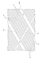
- FIG. 1 is a front view showing the front structure of the battery cooling device of the embodiment.
- FIG. 2 is a perspective view showing a perspective structure of a lower plate member of the embodiment.
- FIG. 3 is an enlarged view showing an enlarged structure around the confluence portion of the lower plate member of the embodiment.
- FIG. 4 is a sectional view showing a partial sectional structure of the plate member of the embodiment.
- FIG. 5 is a plan view showing a planar structure of the first plate member of the embodiment.
- FIG. 6 is a plan view showing a planar structure of the second plate member of the embodiment.
- FIG. 7 is a top view which shows the planar structure of the 1st plate member of other embodiment.
- the battery cooling device 10 of this embodiment shown in FIG. 1 is a device for cooling a plurality of batteries 21 to 24.
- the battery cooling device 10 cools the electric motor for driving the vehicle and the batteries 21 to 24 that supply electric power to various electronic devices mounted on the vehicle.
- the battery cooling device 10 includes a first plate member 30, a second plate member 40, a pipe 50, and a pump 60.
- the batteries 21, 22 are installed on the installation surface 36 of the first plate member 30.
- heat is exchanged between the refrigerant flowing inside the first plate member 30 and the batteries 21 and 22, so that the heat of the batteries 21 and 22 is absorbed by the refrigerant, whereby the batteries 21 and 22 are cooled. ..
- the first plate member 30 is configured by assembling a lower plate member 30a and an upper plate member 30b with each other.
- the lower plate member 30a is formed in a substantially rectangular plate shape.
- the lateral direction of the lower plate member 30a is referred to as "X-axis direction”
- the longitudinal direction of the lower plate member 30a is referred to as “Y-axis direction”
- the thickness direction of the lower plate member 30a is referred to.
- Z-axis direction is referred to as "Z-axis direction”.
- one of the Y-axis directions is referred to as "Y1 direction”
- the opposite direction is also referred to as "Y2 direction”.
- the Z-axis direction is the vertical direction. More specifically, the Z1 direction, which is one of the Z-axis directions, is the upper direction in the vertical direction, and the Z2 direction, which is the opposite direction, is the lower direction in the vertical direction.
- a protrusion 32 is formed on the upper end of one side surface 31a of the lower plate member 30a in the X-axis direction.
- the protruding portion 32 is a portion to which the pipe 50, the pump 60, and the like are connected.
- a concave groove 33 is formed in the lower plate member 30a so as to meander. This groove 33 constitutes a flow path W1 through which the refrigerant flows.
- the flow path W1 is configured as one flow path without branching.
- the flow passage W1 is provided with a plurality of linear flow passage portions W11 to W14 and a plurality of connecting flow passage portions W21 to W23.
- the first to fourth linear flow path portions W11 to W14 are formed so as to linearly extend in the Y-axis direction.
- the fourth linear flow path portion W14 is arranged at a position closest to the one side surface 31a of the lower plate member 30a.
- the third linear flow path portion W13 is arranged at a position closest to the other side surface 31b of the lower plate member 30a.
- the first straight flow passage portion W11 and the second straight flow passage portion W12 are arranged between the third straight flow passage portion W13 and the fourth straight flow passage portion W14. More specifically, the first linear flow passage portion W11 is arranged next to the fourth linear flow passage portion W14.
- the second linear flow passage W12 is arranged next to the third linear flow passage W13.
- the first to third connection flow passage parts W21 to W23 are provided so as to connect the respective ends of two different straight flow passage parts of the first to fourth straight flow passage parts W11 to W14.
- the first connection flow path portion W21 connects the ends of the first straight flow path portion W11 and the second straight flow path portion W12 in the Y2 direction.
- the second connection flow path portion W22 connects the ends of the second straight flow path portion W12 and the third straight flow path portion W13 in the Y1 direction.
- the second connection flow path portion W22 is provided along the one side surface 31c of the lower plate member 30a in the Y1 direction.
- the third connection flow path portion W23 connects the respective ends of the third straight flow path portion W13 and the fourth straight flow path portion W14 in the Y2 direction.
- the third connecting flow passage portion W23 is provided along the other side surface 31d of the lower plate member 30a in the Y1 direction, and is closer to the other side surface 31d of the lower plate member 30a than the first connecting flow passage portion W21. It is located in.
- the lower plate member 30a is formed with an end flow passage W31 so as to extend from the protrusion 32 to one end of the first linear flow passage W11 in the Y1 direction.
- a communication hole 34 is formed at one end of the end channel portion W31 formed in the protrusion 32.
- the lower plate member 30a is formed with an end passage portion W32 so as to extend from the protruding portion 32 to one end portion of the fourth linear passage portion W14 in the Y1 direction.
- a communication hole 35 is formed at one end of the end channel portion W32 formed in the protrusion 32.
- the communication holes 34, 35 are used as parts into which the refrigerant flows in or out.
- a partition wall B is formed in the first to fourth straight flow passage portions W11 to W14, the first connection flow passage portion W21, and the end flow passage portion W32.
- the partition wall B divides each of the flow path portions W11 to W14, W21, W31 into a plurality of small flow paths P in the width direction.
- a merging portion M for merging the plurality of small flow passages P is formed at a substantially central portion of each of the first to fourth linear flow passage portions W11 to W14. As shown in FIG. 3, the small flow paths P communicate with each other at the merging portion M, so that the refrigerants flowing through the small flow passages P can merge through the merging portion M.
- the opening portion of the first linear flow path portion W11 in the vertically upper direction Z1 is closed by the upper plate member 30b assembled on the upper surface of the lower plate member 30a.
- the upper plate member 30b is also used for the opening portions of the other straight flow passage portions W12 to W14, the first to third connection flow passage portions W21 to W23, and the end flow passage portions W31 and W32 in the vertically upper direction Z1. Is blocked by.
- the outer surface 36 of the upper plate member 30b exposed to the outside in the vertically upper direction Z1 is an installation surface on which the batteries 21 and 22 are installed.
- the battery 21 includes a first linear flow path portion W11, a fourth linear flow path portion W14, a right half of the first connecting flow path portion W21, and a third connecting flow path. It is arranged so as to face the right half of the portion W23.
- the battery 22 includes a second linear flow passage W12, a third linear flow passage W13, a left half of the first connecting flow passage W21, a second connecting flow passage W22, and a third connecting flow passage W23. It is arranged to face the left half.
- the two-dot chain lines described in the batteries 21 and 22 indicate the boundaries of the cells forming the batteries 21 and 22.
- the second plate member 40 is arranged vertically below the first plate member 30 in the direction Z2.
- the batteries 23 and 24 are arranged on the installation surface 36 of the second plate member 40. Since the second plate member 40 has the same shape as the first plate member 30, detailed description thereof will be omitted.
- the batteries 23 and 24 are arranged as shown in FIG. 6 with respect to the flow path portions W11 to W14 and W21 to W23 formed in the lower plate member 30a.
- the pipe 50 is arranged so as to extend from the protruding portion 32 of the first plate member 30 to the protruding portion 32 of the second plate member 40.
- the pipe 50 connects the communication hole 34 of the first plate member 30 and the communication hole 34 of the second plate member 40.
- the pump 60 is arranged adjacent to the protrusion 32 of the second plate member 40. The pump 60 pumps the liquid-phase refrigerant into the communication hole 35 of the second plate member 40.
- the liquid-phase refrigerant pumped from the pump 60 first flows into the end flow passage portion W32 of the second plate member 40 through the communication hole 35 of the second plate member 40.
- the refrigerant that has flowed into the end channel portion W32 of the second plate member 40 flows as indicated by the arrow in FIG.
- the refrigerant is the end flow path portion W32 of the second plate member 40, the fourth linear flow path portion W14, the third connecting flow path portion W23, the third linear flow path portion W13, the second connecting flow path portion W22,
- the second straight flow passage portion W12, the first connection flow passage portion W21, the first straight flow passage portion W11, and the end flow passage portion W31 sequentially flow.
- the batteries 23 and 24 are cooled by exchanging heat between the refrigerant flowing through the flow passages W11 to W14 and W21 to W23 and the batteries 23 and 24.
- the refrigerant that has flowed to the end flow path portion W31 in the second plate member 40 flows into the communication hole 34 of the first plate member 30 through the pipe 50 from the communication hole 34 formed at the end portion of the end flow path portion W31. ..
- the refrigerant flowing into the communication hole 34 of the first plate member 30 flows as indicated by the arrow in FIG. That is, the refrigerant is the end channel portion W31, the first linear channel portion W11, the first connecting channel portion W21, the second linear channel portion W12, the second connecting channel portion W22, the third linear channel portion. It flows through W13, the 3rd connection channel part W23, the 4th straight channel part W14, and the end channel part W32 in order. At this time, the batteries 21 and 22 are cooled by exchanging heat between the refrigerant flowing through the flow passages W11 to W14 and W21 to W23 and the batteries 21 and 22.
- the refrigerant that has flowed to the end channel portion W32 in the first plate member 30 is discharged to the outside from the communication hole 35 formed at the end portion of the end channel portion W32 through a pipe (not shown).
- the first straight flow passage portion W11 corresponds to the first flow passage portion arranged on the most upstream side in the flow direction of the refrigerant in the first plate member 30.
- the fourth linear flow passage portion W14 corresponds to the second flow passage portion that is arranged on the most downstream side in the flow direction of the refrigerant in the first plate member 30.
- the first linear flow passage portion W11 corresponding to the first flow passage portion is arranged upstream of the fourth linear flow passage portion W14 corresponding to the second flow passage portion in the flow direction of the refrigerant.
- the liquid-phase refrigerant pumped from the pump 60 to the second plate member 40 exchanges heat with the batteries 23 and 24 in the second plate member 40.
- the temperature of the refrigerant increases toward the downstream side of the flow path W1.
- the liquid-phase refrigerant gradually evaporates, so that the refrigerant flowing from the second plate member 40 into the first plate member 30 is a two-phase refrigerant in which the liquid-phase refrigerant and the gas-phase refrigerant are mixed.
- the battery 21 is arranged so as to face not only the fourth linear flow passage portion W14 but also the first linear flow passage portion W11. Therefore, even if it is difficult to cool the battery 21 only with the refrigerant flowing through the fourth linear flow passage W14, the battery 21 can be cooled with the two-phase refrigerant flowing through the first linear flow passage W11. .. Therefore, the cooling performance of the battery 21 can be improved.
- the battery 21 is arranged on the first plate member 30 so as to face the first linear flow path portion W11 and the fourth linear flow path portion W14.
- the first plate member 30 is arranged so as to exchange heat with the flow path W14. According to such a configuration, even when the temperature of the refrigerant flowing through the downstream fourth linear flow path W14 rises, the battery 21 is cooled by the refrigerant flowing through the upstream first linear flow path W11. Therefore, the cooling performance of the battery 21 can be improved.
- the first plate member 30 and the second plate member 40 of the present embodiment can flow the refrigerant without providing a tank, so compared with a conventional battery cooling device provided with a tank, The battery cooling device can be miniaturized because the tank installation space is unnecessary.
- Each plate member 30, 40 is formed with a partition wall B that divides the flow path W1 through which the refrigerant flows into a plurality of small flow paths P in the width direction.
- the refrigerant flowing through the flow path W1 is divided into a plurality of small flow paths P and flows, so that the distributability of the refrigerant in the flow path W1 can be improved. This allows the batteries 21 to 24 to be cooled more uniformly.
- Each plate member 30, 40 is formed with a merging portion M for merging the middle portions of the plurality of small channels P.
- the refrigerant flows so as to bend in the second connecting flow path portion W22.
- the flow of the refrigerant tends to be biased.
- the deviation of the flow of the refrigerant means the deviation of the flow rates of the vapor-phase refrigerant and the liquid-phase refrigerant.
- the width H22 of the second connection flow path portion W22 is smaller than the width HB of the batteries 22 and 24.
- the entire flow passage portion W22 faces the batteries 22 and 24. Therefore, even if the flow of the refrigerant in the second connection flow passage portion W22 is biased, heat is exchanged between all the refrigerant flowing through the second connection flow passage portion W22 and the batteries 22 and 24. Therefore, it is possible to avoid a decrease in the cooling capacity of the batteries 22 and 24 due to the uneven flow of the refrigerant.
- the width H23 of the third connection flow path portion W23 and the width H31 of the end flow path portion W31 are also smaller than the widths HB of the batteries 21 to 24, respectively. .. Therefore, it is possible to achieve the same action and effect also in the third connection flow path portion W23 and the end flow path portion W31.
- the width H31 of the end flow passage portion W31, the width H22 of the second connection flow passage portion W22, and the width H23 of the third connection flow passage portion W23 are each linear flow passage. It is smaller than the width H10 of the portions W11 to W14.
- the merging portion M may not be formed in each plate member 30, 40.
- the partition wall B may not be formed on each plate member 30, 40.
- the flow path W1 formed in each plate member 30, 40 may not be divided into the plurality of small flow paths P.
- each plate member 30, 40 can be changed appropriately.
- the first plate member 30 may have the flow path W1 as shown in FIG.
- the flow path W1 shown in FIG. 7 is composed of two linear flow path parts W41 and W42 and a connection flow path part W51 that connects the respective end parts thereof.
- Batteries 21 to 24 are arranged on the installation surface 36 of the first plate member 30 so as to face the two linear flow path portions W41 and W42. Even with the first plate member 30 having such a configuration, it is possible to obtain the action and effect similar to the action and effect shown in the above (1).
Landscapes
- Engineering & Computer Science (AREA)
- Manufacturing & Machinery (AREA)
- Chemical & Material Sciences (AREA)
- Chemical Kinetics & Catalysis (AREA)
- Electrochemistry (AREA)
- General Chemical & Material Sciences (AREA)
- Physics & Mathematics (AREA)
- Algebra (AREA)
- General Physics & Mathematics (AREA)
- Mathematical Analysis (AREA)
- Mathematical Optimization (AREA)
- Pure & Applied Mathematics (AREA)
- Secondary Cells (AREA)
Abstract
電池(21,22)と冷媒との熱交換により電池を冷却する電池冷却装置は、冷媒が流れる、分岐のない一つの流路(W1)が形成されるプレート部材(30)を備える。流路は、互いに隣り合うように配置される第1流路部(W11)と第2流路部(W14)とを有している。第1流路部は、冷媒の流れ方向において第2流路部よりも上流側に配置される部分である。電池は、第1流路部と第2流路部との間で熱交換されるようにプレート部材に配置されている。
Description
本出願は、2018年12月14日に出願された日本国特許出願2018-234557号に基づくものであって、その優先権の利益を主張するものであり、その特許出願の全ての内容が、参照により本明細書に組み込まれる。
本開示は、電池を冷却する電池冷却装置に関する。
従来、下記の特許文献1に記載の電池冷却装置がある。特許文献1の電池冷却装置は、複数のチューブと、各チューブの一端部に接続される第1タンクと、各チューブの他端部に接続される第2タンクとを備えている。各チューブの内部には冷媒が流れている。第1タンク及び第2タンクは、各チューブに冷媒を分配したり、各チューブを流れた冷媒を集合させたりする部分である。この電池冷却装置では、複数のチューブに接触するかたちで電池が配置される。各チューブを流れる冷媒と電池との間で熱交換が行われることにより、電池の熱が冷媒に吸収されて、電池が冷却される。
特許文献1に記載の電池冷却装置は、チューブの部分だけに電池が配置可能であるため、タンクの部分は、電池を配置することのできない無駄なスペースになっている。このようにタンクの部分が無駄なスペースになっていることが、電池冷却装置の小型化を妨げる要因の一つとなっている。
また、特許文献1に記載の電池冷却装置では、冷媒が最初に流れるチューブを入口側チューブとし、冷媒が最後に流れるチューブを出口側チューブとするとき、冷媒は、入口側チューブから出口側チューブに向かって流れている間に電池の熱を徐々に吸収する。そのため、入口側チューブを流れる冷媒の温度よりも、出口側チューブを流れる冷媒の温度の方が高くなりやすい。入口側チューブには、通常、液相冷媒が流れているが、電池の熱を吸収することにより冷媒の温度が上昇すると、液相冷媒が気化して気相冷媒となる。仮に出口側チューブを流れる冷媒の全てが気相冷媒になっていると、冷媒の吸熱量が著しく低下するため、電池を十分に冷却できない可能性がある。
本開示の目的は、小型化が可能であるとともに、電池の冷却性能を向上させることの可能な電池冷却装置を提供することにある。
本開示の一態様による電池冷却装置は、電池と冷媒との熱交換により電池を冷却する電池冷却装置であって、冷媒が流れる、分岐のない一つの流路が形成されるプレート部材を備える。流路は、互いに隣り合うように配置される第1流路部と第2流路部とを有している。第1流路部は、冷媒の流れ方向において第2流路部よりも上流側に配置される部分である。電池は、第1流路部と第2流路部との間で熱交換されるようにプレート部材に配置されている。
この構成によれば、タンクを設けることなくプレート部材に冷媒を流すことが可能である。そのため、タンクが設けられている従来の電池冷却装置と比較すると、タンクの設置スペースが不要な分だけ、電池冷却装置の小型化が可能である。
また、プレート部材に形成される流路において、第2流路部よりも上流側に配置されている第1流路部には、第2流路部を流れる冷媒よりも温度の低い冷媒が流れている。そのため、第1流路部と第2流路部との間で熱交換されるように電池が配置されていれば、仮に下流側の第2流路部を流れる冷媒の温度が上昇した場合であっても、第1流路部を流れる冷媒により電池を冷却することができる。よって、電池の冷却性能を向上させることが可能である。
また、プレート部材に形成される流路において、第2流路部よりも上流側に配置されている第1流路部には、第2流路部を流れる冷媒よりも温度の低い冷媒が流れている。そのため、第1流路部と第2流路部との間で熱交換されるように電池が配置されていれば、仮に下流側の第2流路部を流れる冷媒の温度が上昇した場合であっても、第1流路部を流れる冷媒により電池を冷却することができる。よって、電池の冷却性能を向上させることが可能である。
以下、電池冷却装置の一実施形態について図面を参照しながら説明する。説明の理解を容易にするため、各図面において同一の構成要素に対しては可能な限り同一の符号を付して、重複する説明は省略する。
図1に示される本実施形態の電池冷却装置10は、複数の電池21~24を冷却するための機器である。例えば電池冷却装置10が車両に搭載されている場合、電池冷却装置10は、車両を走行させるための電動機や、車両に搭載される各種電子機器に電力を供給する電池21~24を冷却するために用いることが可能である。電池冷却装置10は、第1プレート部材30と、第2プレート部材40と、配管50と、ポンプ60とを備えている。
図1に示される本実施形態の電池冷却装置10は、複数の電池21~24を冷却するための機器である。例えば電池冷却装置10が車両に搭載されている場合、電池冷却装置10は、車両を走行させるための電動機や、車両に搭載される各種電子機器に電力を供給する電池21~24を冷却するために用いることが可能である。電池冷却装置10は、第1プレート部材30と、第2プレート部材40と、配管50と、ポンプ60とを備えている。
第1プレート部材30の設置面36には、電池21,22が設置されている。第1プレート部材30では、その内部を流れる冷媒と電池21,22との間で熱交換が行われることにより、電池21,22の熱を冷媒が吸収することで電池21,22が冷却される。
図1に示されるように、第1プレート部材30は、下側プレート部材30aと上側プレート部材30bとが互いに組み付けられることにより構成されている。
図1に示されるように、第1プレート部材30は、下側プレート部材30aと上側プレート部材30bとが互いに組み付けられることにより構成されている。
図2に示されるように、下側プレート部材30aは、略矩形板状に形成されている。以下では、便宜上、下側プレート部材30aの短手方向を「X軸方向」と称し、下側プレート部材30aの長手方向を「Y軸方向」と称し、下側プレート部材30aの厚さ方向を「Z軸方向」と称する。また、Y軸方向のうちの一方向を「Y1方向」と称し、その逆方向を「Y2方向」とも称する。なお、本実施形態では、Z軸方向が鉛直方向となっている。より詳しくは、Z軸方向のうちの一方向であるZ1方向が鉛直方向上方であり、その逆方向であるZ2方向が鉛直方向下方である。
下側プレート部材30aのX軸方向の一側面31aの上端部には、突出部32が形成されている。突出部32は、配管50やポンプ60等が連結される部分である。
下側プレート部材30aには、凹状の溝33が蛇行するように形成されている。この溝33が、冷媒が流れる流路W1を構成している。流路W1は、分岐のない一つの流路として構成されている。
下側プレート部材30aには、凹状の溝33が蛇行するように形成されている。この溝33が、冷媒が流れる流路W1を構成している。流路W1は、分岐のない一つの流路として構成されている。
具体的には、流路W1には、複数の直線流路部W11~W14と、複数の連結流路部W21~23とが設けられている。
第1~第4直線流路部W11~W14は、Y軸方向に直線状に延びるように形成されている。第4直線流路部W14は、下側プレート部材30aの一側面31aに最も近い位置に配置されている。第3直線流路部W13は、下側プレート部材30aの他側面31bに最も近い位置に配置されている。第1直線流路部W11及び第2直線流路部W12は、第3直線流路部W13と第4直線流路部W14との間に配置されている。より詳しくは、第1直線流路部W11は、第4直線流路部W14の隣に配置されている。また、第2直線流路部W12は、第3直線流路部W13の隣に配置されている。
第1~第4直線流路部W11~W14は、Y軸方向に直線状に延びるように形成されている。第4直線流路部W14は、下側プレート部材30aの一側面31aに最も近い位置に配置されている。第3直線流路部W13は、下側プレート部材30aの他側面31bに最も近い位置に配置されている。第1直線流路部W11及び第2直線流路部W12は、第3直線流路部W13と第4直線流路部W14との間に配置されている。より詳しくは、第1直線流路部W11は、第4直線流路部W14の隣に配置されている。また、第2直線流路部W12は、第3直線流路部W13の隣に配置されている。
第1~第3連結流路部W21~23は、第1~第4直線流路部W11~W14のうちの互いに異なる2つの直線流路部のそれぞれの端部を連結するように設けられている。具体的には、第1連結流路部W21は、第1直線流路部W11及び第2直線流路部W12のY2方向の各端部を連結している。第2連結流路部W22は、第2直線流路部W12及び第3直線流路部W13のY1方向の各端部を連結している。第2連結流路部W22は、下側プレート部材30aのY1方向の一側面31cに沿うように設けられている。第3連結流路部W23は、第3直線流路部W13及び第4直線流路部W14のY2方向の各端部を連結している。第3連結流路部W23は、下側プレート部材30aのY1方向の他側面31dに沿うように設けられており、第1連結流路部W21よりも下側プレート部材30aの他側面31dの近くに配置されている。
下側プレート部材30aには、突出部32から第1直線流路部W11のY1方向の一端部に延びるように端部流路部W31が形成されている。突出部32に形成される端部流路部W31の一端部には、連通孔34が形成されている。下側プレート部材30aには、突出部32から第4直線流路部W14のY1方向の一端部に延びるように端部流路部W32が形成されている。突出部32に形成される端部流路部W32の一端部には、連通孔35が形成されている。連通孔34,35は、冷媒が流入又は排出される部分として用いられる。
第1~第4直線流路部W11~W14、第1連結流路部W21、及び端部流路部W32には、隔壁Bが形成されている。隔壁Bは、各流路部W11~W14,W21,W31を幅方向に複数の小流路Pに分割している。
第1~第4直線流路部W11~W14のそれぞれの略中央部には、複数の小流路Pを合流させる合流部Mが形成されている。図3に示されるように、各小流路Pが合流部Mにおいて互いに連通されることにより、各小流路Pを流れる冷媒が合流部Mを介して合流することが可能となっている。
第1~第4直線流路部W11~W14のそれぞれの略中央部には、複数の小流路Pを合流させる合流部Mが形成されている。図3に示されるように、各小流路Pが合流部Mにおいて互いに連通されることにより、各小流路Pを流れる冷媒が合流部Mを介して合流することが可能となっている。
図4に示されるように、第1直線流路部W11における鉛直方向上方Z1の開口部分は、下側プレート部材30aの上面に組み付けられる上側プレート部材30bにより閉塞されている。他の直線流路部W12~W14、第1~第3連結流路部W21~W23、端部流路部W31,W32のそれぞれの鉛直方向上方Z1の開口部分に関しても、同様に上側プレート部材30bにより閉塞されている。
鉛直方向上方Z1において外部に露出する上側プレート部材30bの外面36は、電池21,22が設置される設置面となっている。具体的には、図5に示されるように、電池21は、第1直線流路部W11、第4直線流路部W14、第1連結流路部W21の右半分、及び第3連結流路部W23の右半分に対向するように配置されている。また、電池22は、第2直線流路部W12、第3直線流路部W13、第1連結流路部W21の左半分、第2連結流路部W22、及び第3連結流路部W23の左半分に対向するように配置されている。なお、図5において、電池21,22に記載される二点鎖線は、電池21,22を構成するセルの境界を示している。
図1に示されるように、第2プレート部材40は、第1プレート部材30に対して鉛直方向下方Z2に配置されている。第2プレート部材40の設置面36には、電池23,24が配置されている。
第2プレート部材40は、第1プレート部材30と同一の形状を有しているため、その詳細な説明は割愛する。第2プレート部材40では、電池23,24が、下側プレート部材30aに形成される各流路部W11~W14,W21~W23に対して図6に示されるように配置されている。
第2プレート部材40は、第1プレート部材30と同一の形状を有しているため、その詳細な説明は割愛する。第2プレート部材40では、電池23,24が、下側プレート部材30aに形成される各流路部W11~W14,W21~W23に対して図6に示されるように配置されている。
図1に示されるように、配管50は、第1プレート部材30の突出部32から第2プレート部材40の突出部32に延びるように配置されている。配管50は、第1プレート部材30の連通孔34と第2プレート部材40の連通孔34とを連通させている。
ポンプ60は、第2プレート部材40の突出部32に隣接して配置されている。ポンプ60は、第2プレート部材40の連通孔35に液相冷媒を圧送する。
ポンプ60は、第2プレート部材40の突出部32に隣接して配置されている。ポンプ60は、第2プレート部材40の連通孔35に液相冷媒を圧送する。
次に、本実施形態の電池冷却装置10の動作例について説明する。
本実施形態の電池冷却装置10では、ポンプ60から圧送される液相冷媒が、はじめに、第2プレート部材40の連通孔35を通じて第2プレート部材40の端部流路部W32に流入する。第2プレート部材40の端部流路部W32に流入した冷媒は、図6に矢印で示されるように流れる。すなわち、冷媒は、第2プレート部材40の端部流路部W32、第4直線流路部W14、第3連結流路部W23、第3直線流路部W13、第2連結流路部W22、第2直線流路部W12、第1連結流路部W21、第1直線流路部W11、及び端部流路部W31を順に流れる。この際、各流路部W11~W14,W21~W23を流れる冷媒と電池23,24との間で熱交換が行われることにより、電池23,24が冷却される。第2プレート部材40において端部流路部W31まで流れた冷媒は、端部流路部W31の端部に形成された連通孔34から配管50を通じて第1プレート部材30の連通孔34に流入する。
本実施形態の電池冷却装置10では、ポンプ60から圧送される液相冷媒が、はじめに、第2プレート部材40の連通孔35を通じて第2プレート部材40の端部流路部W32に流入する。第2プレート部材40の端部流路部W32に流入した冷媒は、図6に矢印で示されるように流れる。すなわち、冷媒は、第2プレート部材40の端部流路部W32、第4直線流路部W14、第3連結流路部W23、第3直線流路部W13、第2連結流路部W22、第2直線流路部W12、第1連結流路部W21、第1直線流路部W11、及び端部流路部W31を順に流れる。この際、各流路部W11~W14,W21~W23を流れる冷媒と電池23,24との間で熱交換が行われることにより、電池23,24が冷却される。第2プレート部材40において端部流路部W31まで流れた冷媒は、端部流路部W31の端部に形成された連通孔34から配管50を通じて第1プレート部材30の連通孔34に流入する。
第1プレート部材30の連通孔34に流入した冷媒は、図5に矢印で示されるように流れる。すなわち、冷媒は、端部流路部W31、第1直線流路部W11、第1連結流路部W21、第2直線流路部W12、第2連結流路部W22、第3直線流路部W13、第3連結流路部W23、第4直線流路部W14、及び端部流路部W32を順に流れる。この際、各流路部W11~W14,W21~W23を流れる冷媒と電池21,22との間で熱交換が行われることにより、電池21,22が冷却される。第1プレート部材30において端部流路部W32まで流れた冷媒は、端部流路部W32の端部に形成された連通孔35から図示しない配管を介して外部に排出される。本実施形態では、第1直線流路部W11が、第1プレート部材30において冷媒の流れ方向の最も上流側に配置される第1流路部に相当する。また、第4直線流路部W14が、第1プレート部材30において冷媒の流れ方向の最も下流側に配置される第2流路部に相当する。第1流路部に相当する第1直線流路部W11は、冷媒の流れ方向において、第2流路部に相当する第4直線流路部W14よりも上流側に配置されている。
ところで、本実施形態の電池冷却装置10では、ポンプ60から第2プレート部材40に圧送される液相冷媒が第2プレート部材40において電池23,24と熱交換を行うため、第2プレート部材40の流路W1の下流側に向かうほど、冷媒の温度が上昇する。これにより、液相冷媒が徐々に気化するため、第2プレート部材40から第1プレート部材30に流入する冷媒は、液相冷媒と気相冷媒とが混合した2相冷媒となっている。
この2相冷媒は第1プレート部材30において電池21,22と熱交換を行うため、第1プレート部材30の流路W1の下流側に向かうほど、冷媒の温度が更に上昇する。そのため、第1プレート部材30において最も下流側に配置される第4直線流路部W14では、冷媒のほとんどが気相状態になっている可能性がある。このように、冷媒のほとんどが気相状態になると、液相状態である場合と比較して、冷媒の吸熱性能が著しく低下する。
この点、本実施形態の電池冷却装置10では、図5に示されるように、電池21が第4直線流路部W14だけでなく第1直線流路部W11に対向するように配置されているため、仮に第4直線流路部W14を流れる冷媒だけでは電池21を冷却することが難しい場合であっても、第1直線流路部W11を流れる2相冷媒により電池21を冷却することができる。よって、電池21の冷却性能を向上させることができる。
以上説明した本実施形態の電池冷却装置10によれば、以下の(1)~(4)に示される作用及び効果を得ることができる。
(1)電池21は、第1直線流路部W11及び第4直線流路部W14に対向するように第1プレート部材30に配置されることにより、第1直線流路部W11と第4直線流路部W14との間で熱交換されるように第1プレート部材30に配置されている。このような構成によれば、下流側の第4直線流路部W14を流れる冷媒の温度が上昇した場合であっても、上流側の第1直線流路部W11を流れる冷媒により電池21を冷却することができるため、電池21の冷却性能を向上させることができる。また、本実施形態の第1プレート部材30及び第2プレート部材40には、タンクを設けることなく冷媒を流すことが可能であるため、タンクが設けられている従来の電池冷却装置と比較すると、タンクの設置スペースが不要な分だけ、電池冷却装置の小型化が可能である。
(1)電池21は、第1直線流路部W11及び第4直線流路部W14に対向するように第1プレート部材30に配置されることにより、第1直線流路部W11と第4直線流路部W14との間で熱交換されるように第1プレート部材30に配置されている。このような構成によれば、下流側の第4直線流路部W14を流れる冷媒の温度が上昇した場合であっても、上流側の第1直線流路部W11を流れる冷媒により電池21を冷却することができるため、電池21の冷却性能を向上させることができる。また、本実施形態の第1プレート部材30及び第2プレート部材40には、タンクを設けることなく冷媒を流すことが可能であるため、タンクが設けられている従来の電池冷却装置と比較すると、タンクの設置スペースが不要な分だけ、電池冷却装置の小型化が可能である。
(2)各プレート部材30,40には、冷媒の流れる流路W1を幅方向に複数の小流路Pに分割する隔壁Bが形成されている。このような構成によれば、流路W1を流れる冷媒が複数の小流路Pに分けられて流れるため、流路W1における冷媒の分配性を向上させることができる。これにより、より均一に電池21~24を冷却することが可能となる。
(3)各プレート部材30,40には、複数の小流路Pの途中部分を合流させる合流部Mが形成されている。このような構成によれば、複数の小流路Pをそれぞれ流れる冷媒を合流部Mで合流させることができるため、流路W1における冷媒の分配性を更に向上させることができる。これにより、更に均一に電池21~24を冷却することが可能となる。
(4)第2直線流路部W12から第2連結流路部W22を介して第3直線流路部W13に冷媒が流れる際に、冷媒は第2連結流路部W22を曲がるように流れるため、第2連結流路部W22では冷媒の流れに偏りが生じ易い。なお、冷媒の流れの偏りとは、気相冷媒及び液相冷媒のそれぞれの流量の偏りである。第2連結流路部W22において冷媒の流れに偏りが生じると、仮に電池が第2連結流路部W22の一部のみに対向するように配置されている場合、第2連結流路部W22において液相冷媒の流量が少ない部分に電池が配置される可能性がある。このように電池が配置されると、電池を十分に冷却できない可能性がある。
この点、本実施形態の電池冷却装置10では、図5及び図6に示されるように、第2連結流路部W22の幅H22が電池22,24の幅HBよりも小さいため、第2連結流路部W22の全体が電池22,24に対向している。そのため、仮に第2連結流路部W22において冷媒の流れに偏りが生じた場合であっても、第2連結流路部W22を流れる冷媒の全てと電池22,24との間で熱交換を行うことができるため、冷媒の流れの偏りに起因する電池22,24の冷却能力の低下を回避することができる。
また、図5及び図6に示されるように、第3連結流路部W23の幅H23、及び端部流路部W31の幅H31も、同様に電池21~24のそれぞれの幅HBよりも小さい。そのため、第3連結流路部W23及び端部流路部W31においても同様の作用及び効果を奏することが可能である。なお、本実施形態の電池冷却装置10では、端部流路部W31の幅H31、第2連結流路部W22の幅H22、及び第3連結流路部W23の幅H23は、各直線流路部W11~W14の幅H10よりも小さくなっている。
なお、上記実施形態は、以下の形態にて実施することもできる。
・各プレート部材30,40には、合流部Mが形成されていなくてもよい。
・各プレート部材30,40には、隔壁Bが形成されていなくてもよい。換言すれば、各プレート部材30,40に形成される流路W1は、複数の小流路Pに分割されていない構成であってもよい。
・各プレート部材30,40には、合流部Mが形成されていなくてもよい。
・各プレート部材30,40には、隔壁Bが形成されていなくてもよい。換言すれば、各プレート部材30,40に形成される流路W1は、複数の小流路Pに分割されていない構成であってもよい。
・各プレート部材30,40の形状は適宜変更可能である。例えば、第1プレート部材30は、図7に示されるような流路W1を有するものであってもよい。図7に示される流路W1は、2つの直線流路部W41,W42と、それらの各端部を連結する連結流路部W51とにより構成されている。この第1プレート部材30の設置面36には、2つの直線流路部W41,W42に対向するように電池21~24が配置されている。このような構成を有する第1プレート部材30でも、上記の(1)に示される作用及び効果に類似する作用及び効果を得ることが可能である。
・本開示は上記の具体例に限定されるものではない。上記の具体例に、当業者が適宜設計変更を加えたものも、本開示の特徴を備えている限り、本開示の範囲に包含される。前述した各具体例が備える各要素、及びその配置、条件、形状等は、例示したものに限定されるわけではなく適宜変更することができる。前述した各具体例が備える各要素は、技術的な矛盾が生じない限り、適宜組み合わせを変えることができる。
Claims (8)
- 電池(21,22)と冷媒との熱交換により前記電池を冷却する電池冷却装置であって、
冷媒が流れる、分岐のない一つの流路(W1)が形成されるプレート部材(30)を備え、
前記流路は、互いに隣り合うように配置される第1流路部(W11)と第2流路部(W14)とを有しており、
前記第1流路部は、冷媒の流れ方向において前記第2流路部よりも上流側に配置される部分であり、
前記電池(21)は、前記第1流路部と前記第2流路部との間で熱交換されるように前記プレート部材に配置されている
電池冷却装置。 - 前記電池(21)は、前記第1流路部及び前記第2流路部に対向するように前記プレート部材に配置されている
請求項1に記載の電池冷却装置。 - 前記プレート部材には、前記流路を幅方向に複数の小流路(P)に分割する隔壁(B)が形成されている
請求項1又は2に記載の電池冷却装置。 - 前記プレート部材には、複数の前記小流路のそれぞれの途中部分を合流させる合流部(M)が形成されている
請求項3に記載の電池冷却装置。 - 前記流路は、
直線状に延びる複数の直線流路部(W11,W12,W13,W14)と、
複数の前記直線流路部のうちの一つの直線流路部(W11)に冷媒を流入させる端部流路部(W31)と、
複数の前記直線流路部のうちの異なる2つの直線流路部のそれぞれの端部を連結するように設けられる連結流路部(W22,W23)と、を有しており、
前記端部流路部及び前記連結流路部のそれぞれの幅は、前記直線流路部の幅よりも小さい
請求項1~4のいずれか一項に記載の電池冷却装置。 - 前記端部流路部及び前記連結流路部のそれぞれの幅は、前記電池の幅よりも小さい
請求項5に記載の電池冷却装置。 - 前記流路は、
直線状に延びる複数の直線流路部(W11,W12,W13,W14)と、
複数の前記直線流路部のうちの一つの直線流路部(W11)に冷媒を流入させる端部流路部(W31)と、
複数の前記直線流路部のうちの異なる2つの直線流路部のそれぞれの端部を連結するように設けられる連結流路部(W22,W23)と、を有しており、
前記第1流路部は、複数の前記直線流路部のうち、冷媒の流れ方向の最も上流側に配置される直線流路部であり、
前記第2流路部は、複数の前記直線流路部のうち、冷媒の流れ方向の最も下流側に配置される直線流路部である
請求項1又は2に記載の電池冷却装置。 - 前記プレート部材に流入する冷媒は、液相冷媒と気相冷媒とが混合した2相冷媒である
請求項1~7のいずれか一項に記載の電池冷却装置。
Applications Claiming Priority (2)
| Application Number | Priority Date | Filing Date | Title |
|---|---|---|---|
| JP2018234557A JP2020095912A (ja) | 2018-12-14 | 2018-12-14 | 電池冷却装置 |
| JP2018-234557 | 2018-12-14 |
Publications (1)
| Publication Number | Publication Date |
|---|---|
| WO2020121922A1 true WO2020121922A1 (ja) | 2020-06-18 |
Family
ID=71076020
Family Applications (1)
| Application Number | Title | Priority Date | Filing Date |
|---|---|---|---|
| PCT/JP2019/047484 Ceased WO2020121922A1 (ja) | 2018-12-14 | 2019-12-04 | 電池冷却装置 |
Country Status (2)
| Country | Link |
|---|---|
| JP (1) | JP2020095912A (ja) |
| WO (1) | WO2020121922A1 (ja) |
Cited By (1)
| Publication number | Priority date | Publication date | Assignee | Title |
|---|---|---|---|---|
| DE102024109025A1 (de) * | 2024-03-28 | 2025-10-02 | Mahle International Gmbh | Wärmeübertragerplatte und zugehörige Verwendung sowie Anordnung einer Traktionsbatterie an einer Wärmeübertragerplatte |
Families Citing this family (1)
| Publication number | Priority date | Publication date | Assignee | Title |
|---|---|---|---|---|
| KR102867401B1 (ko) * | 2021-05-07 | 2025-09-30 | 주식회사 엘지에너지솔루션 | 전지팩 및 이를 포함하는 디바이스 |
Citations (2)
| Publication number | Priority date | Publication date | Assignee | Title |
|---|---|---|---|---|
| JP2009277471A (ja) * | 2008-05-14 | 2009-11-26 | Toyota Motor Corp | 電池ホルダ |
| WO2013171885A1 (ja) * | 2012-05-17 | 2013-11-21 | 日立ビークルエナジー株式会社 | 電池モジュール |
-
2018
- 2018-12-14 JP JP2018234557A patent/JP2020095912A/ja active Pending
-
2019
- 2019-12-04 WO PCT/JP2019/047484 patent/WO2020121922A1/ja not_active Ceased
Patent Citations (2)
| Publication number | Priority date | Publication date | Assignee | Title |
|---|---|---|---|---|
| JP2009277471A (ja) * | 2008-05-14 | 2009-11-26 | Toyota Motor Corp | 電池ホルダ |
| WO2013171885A1 (ja) * | 2012-05-17 | 2013-11-21 | 日立ビークルエナジー株式会社 | 電池モジュール |
Cited By (1)
| Publication number | Priority date | Publication date | Assignee | Title |
|---|---|---|---|---|
| DE102024109025A1 (de) * | 2024-03-28 | 2025-10-02 | Mahle International Gmbh | Wärmeübertragerplatte und zugehörige Verwendung sowie Anordnung einer Traktionsbatterie an einer Wärmeübertragerplatte |
Also Published As
| Publication number | Publication date |
|---|---|
| JP2020095912A (ja) | 2020-06-18 |
Similar Documents
| Publication | Publication Date | Title |
|---|---|---|
| KR102731937B1 (ko) | 배터리 셀을 냉각하기 위한 구조체 및 이를 포함하는 배터리 시스템 | |
| JP7539207B2 (ja) | 冷却装置および車両 | |
| CN111033877A (zh) | 冷却装置及电池调温系统 | |
| JP5423337B2 (ja) | 積層型冷却器 | |
| WO2019043801A1 (ja) | ヒートシンク | |
| US7219511B2 (en) | Evaporator having heat exchanging parts juxtaposed | |
| EP3059542A1 (en) | Laminated header, heat exchanger, and air-conditioner | |
| JP2020079693A (ja) | 熱交換器 | |
| WO2013160956A1 (ja) | 熱交換器用ヘッダ及びこの熱交換器用ヘッダを備えた熱交換器 | |
| WO2020121922A1 (ja) | 電池冷却装置 | |
| KR20230061523A (ko) | 배터리 팩 | |
| KR20120080625A (ko) | 비등 냉각식 열교환기 | |
| JP7209220B2 (ja) | 冷却装置および筐体 | |
| JP7031524B2 (ja) | 冷却器 | |
| JP4568581B2 (ja) | プレート型熱交換器 | |
| CN113678303B (zh) | 冷却装置以及壳体 | |
| EP4067800A1 (en) | Heat exchanger | |
| JP2014107038A (ja) | バッテリークーラー | |
| CN103097847B (zh) | 热交换器 | |
| US9989314B2 (en) | Heat exchanger assembly | |
| KR101844296B1 (ko) | 차량용 열교환기 | |
| JP2019054224A (ja) | 液冷式冷却装置 | |
| JP2016038120A (ja) | 熱交換器 | |
| US7845392B2 (en) | Heat exchanger assembly | |
| WO2020022104A1 (ja) | 車両の冷却システム |
Legal Events
| Date | Code | Title | Description |
|---|---|---|---|
| 121 | Ep: the epo has been informed by wipo that ep was designated in this application |
Ref document number: 19894864 Country of ref document: EP Kind code of ref document: A1 |
|
| NENP | Non-entry into the national phase |
Ref country code: DE |
|
| 122 | Ep: pct application non-entry in european phase |
Ref document number: 19894864 Country of ref document: EP Kind code of ref document: A1 |