WO2020121901A1 - Optical transmission system, optical transmission device, optical receiving device, and transfer function estimation method - Google Patents
Optical transmission system, optical transmission device, optical receiving device, and transfer function estimation method Download PDFInfo
- Publication number
- WO2020121901A1 WO2020121901A1 PCT/JP2019/047309 JP2019047309W WO2020121901A1 WO 2020121901 A1 WO2020121901 A1 WO 2020121901A1 JP 2019047309 W JP2019047309 W JP 2019047309W WO 2020121901 A1 WO2020121901 A1 WO 2020121901A1
- Authority
- WO
- WIPO (PCT)
- Prior art keywords
- signal
- speed signal
- optical
- speed
- low
- Prior art date
Links
Images


Classifications
-
- H—ELECTRICITY
- H04—ELECTRIC COMMUNICATION TECHNIQUE
- H04B—TRANSMISSION
- H04B10/00—Transmission systems employing electromagnetic waves other than radio-waves, e.g. infrared, visible or ultraviolet light, or employing corpuscular radiation, e.g. quantum communication
- H04B10/50—Transmitters
- H04B10/58—Compensation for non-linear transmitter output
-
- H—ELECTRICITY
- H04—ELECTRIC COMMUNICATION TECHNIQUE
- H04B—TRANSMISSION
- H04B10/00—Transmission systems employing electromagnetic waves other than radio-waves, e.g. infrared, visible or ultraviolet light, or employing corpuscular radiation, e.g. quantum communication
- H04B10/50—Transmitters
- H04B10/516—Details of coding or modulation
-
- H—ELECTRICITY
- H04—ELECTRIC COMMUNICATION TECHNIQUE
- H04B—TRANSMISSION
- H04B10/00—Transmission systems employing electromagnetic waves other than radio-waves, e.g. infrared, visible or ultraviolet light, or employing corpuscular radiation, e.g. quantum communication
- H04B10/50—Transmitters
- H04B10/501—Structural aspects
- H04B10/503—Laser transmitters
- H04B10/505—Laser transmitters using external modulation
- H04B10/5053—Laser transmitters using external modulation using a parallel, i.e. shunt, combination of modulators
-
- H—ELECTRICITY
- H04—ELECTRIC COMMUNICATION TECHNIQUE
- H04B—TRANSMISSION
- H04B10/00—Transmission systems employing electromagnetic waves other than radio-waves, e.g. infrared, visible or ultraviolet light, or employing corpuscular radiation, e.g. quantum communication
- H04B10/60—Receivers
- H04B10/61—Coherent receivers
- H04B10/616—Details of the electronic signal processing in coherent optical receivers
-
- H—ELECTRICITY
- H04—ELECTRIC COMMUNICATION TECHNIQUE
- H04B—TRANSMISSION
- H04B10/00—Transmission systems employing electromagnetic waves other than radio-waves, e.g. infrared, visible or ultraviolet light, or employing corpuscular radiation, e.g. quantum communication
- H04B10/60—Receivers
- H04B10/66—Non-coherent receivers, e.g. using direct detection
- H04B10/69—Electrical arrangements in the receiver
- H04B10/697—Arrangements for reducing noise and distortion
-
- H—ELECTRICITY
- H04—ELECTRIC COMMUNICATION TECHNIQUE
- H04L—TRANSMISSION OF DIGITAL INFORMATION, e.g. TELEGRAPHIC COMMUNICATION
- H04L27/00—Modulated-carrier systems
- H04L27/26—Systems using multi-frequency codes
Definitions
- the present invention relates to an optical transmission system, an optical transmitter, an optical receiver, and a transfer function estimation method.
- Patent Document 1 As a technique for compensating the imperfections of the analog circuit as described above, the techniques shown in Patent Document 1 and Non-Patent Document have been proposed.
- an optical transmitter or an optical receiver re-separates a high-speed signal generated by the above technique into a plurality of low-speed signals, thereby estimating and estimating a transfer function in the low-speed signal.
- the transfer function is updated using the transfer function.
- the technique disclosed in Non-Patent Document 4 uses a digital filter capable of simultaneously compensating for a transfer function for a low speed signal and a transfer function for a high speed signal.
- the present invention aims to provide a technique capable of improving deterioration of signal quality.
- One aspect of the present invention is an optical transmission system including an optical transmitter and an optical receiver, wherein the optical transmitter includes an input signal of a transmission data sequence and a signal obtained by cyclically shifting a spectrum of the input signal.
- a low-speed signal generation unit that generates a plurality of low-speed signals based on the above, a high-speed signal generation unit that generates a high-speed signal by performing digital-analog conversion of the plurality of low-speed signals and combining, and a high-speed signal modulated light
- An optical modulator for transmitting a signal to a transmission path, wherein the optical receiver receives the optical signal from the transmission path, and a receiver for outputting the high-speed signal obtained from the received optical signal,
- An optical receiver-side high-speed signal compensator for compensating the high-speed signal based on the high-speed signal output from the receiver and a signal obtained by cyclically shifting the spectrum of the high-speed signal, and the optical receiver-side high-speed signal compensator
- An optical transmission system comprising:
- One aspect of the present invention is an optical transmission system, wherein the optical transmitter multiplies an input signal of a transmission data sequence and a signal obtained by cyclically shifting the spectrum of the input signal by a transfer function,
- the transmitter-side high-speed signal compensator for compensating the input signal by adding multiplication results is further provided, and the low-speed signal generator includes the plurality of the input signals compensated by the transmitter-side high-speed signal compensator.
- the optical receiver side high speed signal compensator multiplies each of the high speed signal output by the receiver and the signal obtained by cyclically shifting the spectrum of the high speed signal by a transfer function. , The high speed signal is compensated by adding the multiplication results.
- One aspect of the present invention is an optical transmission system, wherein the low-speed signal generation unit multiplies each of an input signal of a transmission data sequence and a signal obtained by cyclically shifting the spectrum of the input signal by a transfer function. , The plurality of low speed signals are generated from the compensated input signals by adding the multiplication results, and the optical receiver side high speed signal compensating unit outputs the high speed signals output from the receiving unit.
- the high-speed signal is compensated by multiplying each of the signal and the signal obtained by cyclically shifting the spectrum of the high-speed signal by the transfer function and adding the multiplication results.
- One aspect of the present invention is an optical transmission system, wherein the optical receiver calculates a transfer function based on a difference between an output signal of the optical receiver-side high-speed signal compensator and a reference signal.
- the function estimating unit is further provided.
- One aspect of the present invention is an optical transmission system, wherein the transfer function estimation unit calculates the transfer function by using a part of the transmission data sequence that is predetermined as a known signal as the reference signal, or The transfer function is calculated by using the hard-decision value of the output of the high-speed signal compensator on the optical receiver side as the reference signal.
- One aspect of the present invention is an optical transmitter in an optical transmission system including an optical transmitter and an optical receiver, which is based on an input signal of a transmission data sequence and a signal obtained by cyclically shifting a spectrum of the input signal.
- a low-speed signal generation unit that generates a plurality of low-speed signals
- a high-speed signal generation unit that digital-analog converts the plurality of low-speed signals to generate a high-speed signal
- an optical signal that modulates the high-speed signal.
- An optical transmitter including: an optical modulator that transmits to a transmission path.
- One aspect of the present invention is an optical receiver in an optical transmission system including an optical transmitter and an optical receiver, and receives an optical signal transmitted from the optical transmitter via a transmission path and receives the optical signal.
- a receiver that outputs a high-speed signal obtained from the optical signal, a high-speed signal compensator that compensates the high-speed signal based on the high-speed signal output by the receiver and a signal obtained by cyclically shifting the spectrum of the high-speed signal.
- a received data decoding unit that restores the binary information contained in the optical signal transmitted by the optical transmitter by decoding the high speed signal compensated by the optical receiver side high speed signal compensating unit. It is an optical receiver.
- One aspect of the present invention is a transfer function estimation method in an optical transmission system including an optical transmitter and an optical receiver, wherein the optical transmitter outputs an input signal of a transmission data sequence and a spectrum of the input signal.
- a low-speed signal generation step of generating a plurality of low-speed signals based on the cyclically-shifted signal; a high-speed signal generation step of digital-analog converting the plurality of low-speed signals to generate a high-speed signal, and the high-speed signal
- An optical modulation step of transmitting an optical signal obtained by modulating a signal to a transmission line, wherein the optical receiver receives the optical signal from the transmission line, and receives the high-speed signal obtained from the received optical signal.
- An optical receiver-side high-speed signal compensating step for compensating the high-speed signal based on a receiving step of outputting, the high-speed signal output in the receiving step, and a signal obtained by cyclically shifting the spectrum of the high-speed signal,
- the present invention makes it possible to improve the deterioration of signal quality.
- FIG. 1 It is a block diagram which shows the structure of the optical transmission system in this invention. It is a figure which shows the internal structure of a transmission signal generation part. It is a figure which shows the internal structure of a high-speed signal compensation part. It is a figure showing an example of generation of a low-speed signal in a low-speed signal generation part of this embodiment. It is a figure which shows the internal structure of a high-speed signal generation part. It is a figure which shows the internal structure of an analog multiplexing part. It is a figure which shows the internal structure of a high-speed signal compensation part. It is a sequence diagram which shows the flow of a process of an optical transmission system. It is a figure for demonstrating the effect acquired by this invention.
- FIG. 1 shows the internal structure of a transmission signal generation part. It is a figure which shows the internal structure of a high-speed signal compensation part. It is a figure showing an example of generation of a low-speed signal in a low-speed signal generation part of this embodiment. It is a
- FIG. 16 is a diagram showing an example of low-speed signal generation in a low-speed signal generation unit when the technique of the present invention is applied to the analog multiplexing system shown in Non-Patent Document 1. It is a figure which shows the internal structure of the analog multiplex part at the time of applying the technique of this invention to the analog multiplex system shown in nonpatent literature 1.
- FIG. 16 is a diagram showing an example of low-speed signal generation in a low-speed signal generation unit when the technique of the present invention is applied to the analog multiplexing method shown in Non-Patent Document 4.
- FIG. 11 is a diagram showing an internal configuration of an analog multiplexing unit when the technique of the present invention is applied to the analog multiplexing system shown in Non-Patent Document 4.
- FIG. 1 is a block diagram showing the configuration of an optical transmission system 100 according to the present invention.
- the optical transmission system 100 includes an optical transmitter 10 and an optical receiver 20.
- the optical transmitter 10 and the optical receiver 20 are connected via a transmission line 30. Further, the optical transmitter 10 and the optical receiver 20 are connected via a communication line 40.
- the transmission path 30 is a path for transmitting the optical signal transmitted from the optical transmitter 10 to the optical receiver 20.
- the transmission line 30 is composed of an optical fiber 30-1 and an optical amplifier 30-2.
- the optical signal output from the optical transmitter 10 is transmitted by the optical fiber 30-1, amplified by the optical amplifier 30-2, and received by the optical receiver 20.
- the communication line 5 is used when the transfer function calculated by the optical receiver 20 is transmitted to the optical transmitter 10.
- the communication line 5 is, for example, a communication channel or a control channel such as NE-Ops (Network Element Operation System) or NW-Ops (Network Operation System).
- the optical transmitter 10 includes a digital signal processing unit 11, a high speed signal generation unit 12, and an optical modulation unit 13.
- the terms low speed and high speed in the terms low speed signal and high speed signal indicate the narrowness and width of the analog bandwidth.
- the bandwidth of the high speed signal is fc [GHz]
- the bandwidth of the low speed signal is a value smaller than fc [GHz].
- the bandwidth is about high-speed signal ⁇ low-speed signal ⁇ N (N is an integer and the number of DACs (Digital-to-Analog Converters)).
- the digital signal processing unit 11 performs digital signal processing on a transmission data sequence that is binary information supplied from the outside.
- the digital signal processing unit 11 includes a transmission signal generation unit 14, a high speed signal compensation unit 15, and a low speed signal generation unit 16.
- the transmission signal generator 14 generates a modulated signal sequence (XI, XQ, YI, YQ) which is a high speed signal.
- the transmission signal generation unit 14 has the internal configuration shown in FIG. 2 and includes a bit mapping unit 141 and a waveform shaping unit 142.
- the bit mapping unit 141 allocates transmission bits to symbol points such as QPSK (Quadrature Phase Shift Keying) and 16QAM (Quadrature Amplitude Modulation) for the transmission data series, and the modulated signal series (XI, XQ) that are high-speed signals. , YI, YQ) is generated.
- QPSK Quadrature Phase Shift Keying
- 16QAM Quadrature Amplitude Modulation
- the waveform shaping unit 142 performs a filtering process on each of the modulated signal sequences (XI, XQ, YI, YQ) output by the bit mapping unit 141. Filters such as Raised Cosine Filter and Root Raised Cosine Filter are used for the filtering process.
- the waveform shaping section 142 may perform arbitrary signal processing such as pre-chromatic dispersion compensation for compensating for waveform distortion on the transmission path or pre-linear nonlinear effect compensation.
- the high-speed signal compensating unit 15 compensates the frequency characteristic based on the modulated signal series (XI, XQ, YI, YQ) whose waveform has been shaped and the transfer function obtained from the optical receiver 20.
- a method for compensating the frequency characteristic based on the transfer function any method can be applied, and for example, an FIR (Finite Impulse Response) filter, an IIR (Infinite Impulse Response) filter, or a discrete Fourier transform is used.
- a digital signal processing method using an equalizer in the frequency domain or an analog method using an analog filter such as a phase shifter or a delay line is applied.
- the high-speed signal compensator 15 compensates the frequency characteristic for each modulated signal series (XI, XQ, YI, YQ) whose waveform has been shaped. Note that the high-speed signal compensator 15 may perform arbitrary signal processing such as pre-chromatic dispersion compensation for compensating for waveform distortion on the transmission path or pre-linear optical effect compensation.
- the high speed signal compensator 15 has the internal configuration shown in FIG. 3, and includes a plurality of frequency shifters 151-1 to 151-3 and a high speed signal equalizer 152.
- the one-lane high-speed signal (XI) output by the waveform shaping unit 142 is described as an example, but the high-speed signal compensating unit 15 outputs the four-lane high-speed signal output by the waveform shaping unit 142. Similar processing is performed for each of (XI, XQ, YI, YQ).
- the frequency shift units 151-1 to 151-3 cyclically shift the spectrum of the input modulation signal sequence in frequency. Specifically, the frequency shifter 151-1 shifts the spectrum of the input modulated signal sequence by one to the left.
- the frequency shifter 151-2 shifts the spectrum of the input modulated signal sequence by two to the left.
- the frequency shifter 151-3 shifts the spectrum of the input modulation signal sequence by three to the left.
- the number of cyclic shifts depends on the number of divided spectra.
- the present invention rearranges the divided spectrums on the frequency axis and performs processing so that each spectrum component after division appears in all frequency bands.
- One method of realizing this processing is “cyclic shift” performed by the frequency shift units 151-1 to 151-3.
- the high-speed signal of the input modulated signal sequence is R 0 (f)
- the high-speed signal in which the spectrum of the high-speed signal R 0 (f) is shifted by the frequency shifter 151-1 is R 1 ( f)
- the high speed signal R 0 (f) obtained by shifting the spectrum of the high speed signal R 0 (f) by the frequency shift unit 151-2 is defined as R 2 (f)
- the spectrum of the high speed signal R 0 (f) by the frequency shift unit 151-3 Let the high-speed signal shifted by R 3 (f).
- the high-speed signal equalization unit 152 receives the transfer function (A 0 (A 0 (f 0 )) for each of the input high-speed signals (R 0 (f), R 1 (f), R 2 (f), R 3 (f)). f), A 1 (f), A 2 (f), A 3 (f)) are multiplied and the multiplication results are added to compensate for the high speed signal.
- the high speed signal equalizer 152 includes a plurality of multipliers 153-1 to 153-4 and an adder 154.
- the multipliers 153-1 to 153-4 multiply the input high speed signal by the transfer function. Specifically, the multiplier 153-1 receives the high-speed signal R 0 (f) of the modulated signal sequence output from the waveform shaping unit 142 as it is, and the multiplier 153-2 uses the frequency shift unit 151-1. The high frequency signal R 1 (f) cyclically shifted in frequency is input, and the high speed signal R 2 (f) cyclically shifted in frequency by the frequency shifter 151-2 is input to the multiplier 153-3. The multiplier 153-4 receives the high-speed signal R 3 (f) cyclically shifted in frequency by the frequency shifter 151-3.
- the transfer functions A 0 (f), A 1 (f), A 2 (f) and A 3 (f) input to the multipliers 153-1 to 153-4 are calculated by the optical receiver 20. ..
- the multiplier 153-1 multiplies the high-speed signal R 0 (f) by the transfer function A 0 (f), and outputs the multiplication result to the adder 154.
- the multiplier 153-2 multiplies the high-speed signal R 1 (f) by the transfer function A 1 (f) and outputs the multiplication result to the adder 154.
- the multiplier 153-3 multiplies the high-speed signal R 2 (f) by the transfer function A 2 (f), and outputs the multiplication result to the adder 154.
- the multiplier 153-4 multiplies the high-speed signal R 3 (f) by the transfer function A 3 (f) and outputs the multiplication result to the adder 154.
- the adder 154 adds the multiplication results output from the multipliers 153-1 to 153-4. As a result, the high speed signal S(f) is generated.
- the adder 154 outputs the generated high speed signal S(f) to the low speed signal generator 16.
- the high speed signal S(f) is expressed by the following equation (1).
- the high-speed signal compensating unit 15 performs the convolution operation of the transfer function on the input modulated signal sequence and the signal obtained by frequency-shifting the modulated signal sequence, and generates the low-speed signal of the sum of the convolution operation results. It is output to the unit 16.
- the low-speed signal generator 16 decomposes the high-speed signal S(f) output from the high-speed signal compensator 15 into a plurality of low-speed signals, and outputs the low-speed signals to the high-speed signal generators 12-1 to 12-4. Specifically, the low-speed signal generation unit 16 performs signal processing so that a desired signal is generated when the low-speed signals to be output are combined by the high-speed signal generation units 12-1 to 12-4, and the low-speed signal generation unit 16 Generate a signal.
- a method of generating the low-speed signal for example, a signal obtained by dividing the high-speed signal S(f) output from the high-speed signal compensator 15 in the frequency domain, folding the high-frequency component, and adding the low-frequency component and the high-frequency component, A signal obtained by subtracting the high frequency component from the low frequency component is generated as a low speed signal.
- the method of generating the low-speed signal is not limited to the above method.
- the low speed signal generation unit 16 has a function of generating a plurality of low speed signals from the high speed signal for each of the four lanes of the high speed signal (XI, XQ, YI, YQ). For example, the low speed signal generation unit 16 generates a plurality of low speed signals (XI 1 , XI 2 ) from the high speed signal (XI). In addition, for example, the low speed signal generation unit 16 generates a plurality of low speed signals (XQ 1 , XQ 2 ) from the high speed signal (XQ). Further, for example, the low speed signal generation unit 16 generates a plurality of low speed signals (YI 1 , YI 2 ) from the high speed signal (YI).
- the low speed signal generation unit 16 generates a plurality of low speed signals (YQ 1 , YQ 2 ) from the high speed signal (YQ). Further, the processing performed by the low-speed signal generation unit 16 described above uses high-speed signal compensation by using the coefficients of the transfer functions A 0 to A M (M is an integer of 1 or more) input to the high-speed signal compensation unit 15. You may carry out simultaneously. That is, the high speed signal compensator 15 and the low speed signal generator 16 may be configured as one functional unit. When configured in this way, the low-speed signal generator 16 has a function included in the high-speed signal compensator 15. That is, the low-speed signal generation unit 16 multiplies each of the input signal of the transmission data sequence and the signal obtained by cyclically shifting the spectrum of the input signal by the transfer function and adds the multiplication results to compensate the input signal. ..
- FIG. 4 is a diagram showing an example of low-speed signal generation in the low-speed signal generator 16 of this embodiment.
- 4A shows the spectrum of the high-speed signal S(f) input to the low-speed signal generator 16
- FIG. 4B shows the spectrum of the first low-speed signal generated by the low-speed signal generator 16.
- 4C shows the spectrum of the second low speed signal generated by the low speed signal generator 16.
- the first low-speed signal is obtained by dividing the high-speed signal S(f) input by the low-speed signal generator 16 in the frequency domain, shifting the high-frequency component, and adding the low-frequency component and the high-frequency component.
- the second low-speed signal divides the input high-speed signal S(f) in the frequency domain, shifts the high-frequency component, and shifts the high-frequency component to the high-frequency component as described above. It is generated by subtracting the components.
- the high-speed signal generation units 12-1 to 12-4 have the same internal configuration.
- FIG. 5 shows the internal configuration of the high-speed signal generation unit 12-1.
- the high speed signal generation unit 12-1 includes two DACs 121-1 and 122-1 and an analog multiplexing unit 123-1.
- the DACs 121-1 and 122-1 convert the first low speed signal (XI 1 ) and the second low speed signal (XI 2 ) which are digital signals into analog signals, respectively.
- the analog multiplexing unit 123-1 generates a high-speed signal by modulating the analog signals converted by the DACs 121-1 and 122-1 with a clock having a predetermined frequency and synthesizing the modulated analog signals. In this way, by using the two DACs 121-1 and 122-1, the bandwidth required for each of the two DACs 121-1 and 122-1 can be reduced as compared with the case where a high speed signal is generated by a single DAC. It can be significantly reduced.
- FIG. 6 is a diagram showing an internal configuration of the analog multiplexing unit 123-1.
- the analog multiplexing unit 123-1 includes a high speed switching circuit 1231, a high speed switching circuit 1232, a phase delay circuit 1233 and an adder 1234.
- the high-speed switching circuit 1231 has ch1p and ch1n as input terminals.
- An analog signal (low-speed signal) output from the DAC 121-1 is input to ch1p, and an analog signal (low-speed signal) whose polarity is inverted from that of the analog signal output from the DAC 121-1 is input to ch1n. ..
- the analog signal input to the high-speed switching circuit 1231 is modulated by the clock generated by the clock generator 124 that outputs a clock having a predetermined frequency (for example, f UB /2).
- the modulated first low speed signal is input to the adder 1234.
- the high speed switching circuit 1232 has ch2p and ch2n as input terminals.
- An analog signal (low speed signal) output from the DAC 122-1 is input to ch2p, and an analog signal (low speed signal) whose polarity is inverted from that of the analog signal output from the DAC 122-1 is input to ch2n. ..
- the analog signal input to the high-speed switching circuit 1232 is modulated by the clock generated by the clock generator 124 with a phase delay of ⁇ /2.
- the modulated second low speed signal is input to the adder 1234.
- the high-speed switching circuit 1231 and the high-speed switching circuit 1232 can be represented as equivalent circuits by multiplication of cos(wt) on the ch1 side and sin(wt) on the ch2 side.
- the phase delay circuit 1233 is a circuit that delays the input clock. In the example shown in FIG. 6, the phase delay circuit 1233 gives a phase delay of ⁇ /2 for the input clock.
- the adder 1234 adds the modulated first low speed signal output from the high speed switching circuit 1231 and the modulated second low speed signal output from the high speed switching circuit 1232.
- the modulated signals (after up-conversion) are added, and the spectral components with inverted polarities in the spectra of the first and second low-speed signals after up-conversion are canceled and only the spectral components of the same polarity remain, leaving the high-speed signal. Will be rebuilt.
- Non-Patent Document 1 Similar crosstalk occurs due to incompleteness of the device. Further, spurious (existence at a position other than the desired clock frequency) in the high-speed switching circuits 1231 and 1232. Signal), a low-speed signal is modulated in an unintended band, and crosstalk occurs between subbands.In the present invention, crosstalk between subbands is compensated for by digital signal processing. However, if there is crosstalk due to other device imperfections, the required number of cyclic shifts is M.
- a signal that is cyclically shifted by the spurious frequency is used in the high-speed signal compensator. It is also possible to compensate for crosstalk between subbands due to spurious by adding 15 to this case, in which case the required number of cyclic shifts is larger than M.
- the optical modulator 13 modulates a high speed signal into an optical signal.
- the optical modulator 13 is a polarization multiplexing IQ modulator including a polarization multiplexing Mach-Zehnder type vector modulator, a driver amplifier, and a laser module.
- driver amplifiers installed in the respective lanes are provided for the high speed signals (XI, XQ, YI, YQ) of four lanes output from the high speed signal generators 12-1 to 12-4. Amplification is performed, and the amplified high-speed signal is output as a modulation signal to the polarization multiplexing Mach-Zehnder type vector modulator.
- the polarization multiplexing type Mach-Zehnder type vector modulator modulates the optical signal from the laser module based on the modulation signal and outputs the modulated optical signal to the transmission line 30.
- the optical receiver 20 includes an optical demodulator 21, a transmission path compensator 22, a high speed signal compensator 23, a received data decoder 24, and a transfer function estimator 25.
- the optical demodulator 21 demodulates the optical signal transmitted from the optical transmitter 10.
- the optical demodulator 21 includes an optical receiver 26 and a plurality of ADCs 27-1 to 27-4.
- the optical receiver 26 has a laser module inside, and converts an optical signal received via the transmission path 30 into a baseband signal by local light emission from the laser module and outputs it as an electric signal.
- the optical receiver 26 may output the optical signal received via the transmission line 30 as an electrical signal by direct detection.
- the ADCs 27-1 to 27-4 convert analog electric signals into digital electric signals and output the digital electric signals.
- the transmission line compensator 22 compensates for the chromatic dispersion, the polarization fluctuation, and the waveform deterioration due to the nonlinear optical effect that occur in the transmission line 30.
- the high-speed signal compensator 23 compensates the frequency characteristic based on the electric signal compensated by the transmission path compensator 22 and the transfer function obtained from the transfer function estimator 25.
- the high speed signal compensator 23 has the same configuration as the high speed signal compensator 15.
- the high speed signal compensating unit 23 has the internal configuration shown in FIG. 7, and includes a plurality of frequency shift units 231-1 to 231-3 and a high speed signal equalizing unit 232.
- the high-speed signal (XI) of one lane output by the transmission path compensator 22 is described as an example, but the high-speed signal compensator 23 includes four lanes of four lanes output by the transmission path compensator 22. Similar processing is performed for each of the high speed signals (XI, XQ, YI, YQ).
- the frequency shift units 231-1 to 231-3 cyclically shift the spectrum of the input modulation signal sequence in frequency. Specifically, the frequency shifter 231-1 shifts the spectrum of the input modulated signal sequence by one to the left. The frequency shifter 231-2 shifts the spectrum of the input modulation signal sequence by two to the left. The frequency shift unit 231-3 shifts the spectrum of the input modulation signal sequence by three to the left.
- the high-speed signal of the input modulated signal sequence is R′ 0 (f)
- the high-speed signal whose spectrum of the high-speed signal R′ 0 (f) has been shifted by the frequency shifter 231-1 is R′ 0 (f).
- the high speed signal R′ 0 (f) whose spectrum is shifted by the frequency shifter 231-2 is R′ 2 (f)
- the frequency shifter 151-3 outputs the high speed signal R′.
- a high-speed signal whose spectrum of 0 (f) is shifted is defined as R′ 3 (f).
- the high-speed signal equalization unit 232 transfers the transfer function for each of the plurality of input high-speed signals (R′ 0 (f), R′ 1 (f), R′ 2 (f), R′ 3 (f)). (A 0 (f), A 1 (f), A 2 (f), A 3 (f)) are multiplied and the multiplication results are added to compensate for the high speed signal.
- the high speed signal equalizer 232 includes a plurality of multipliers 233-1 to 233-4 and an adder 234.
- the multipliers 233-1 to 233-4 multiply the input high speed signal by the transfer function. Specifically, the high speed signal R′ 0 (f) output from the transmission path compensator 22 is directly input to the multiplier 233-1, and the multiplier 233-2 uses the frequency shifter 231-1 to adjust the frequency. The high-speed signal R′ 1 (f) cyclically shifted to is input to the multiplier 233-3, and the high-speed signal R′ 2 (f) cyclically shifted in frequency by the frequency shifter 231-2 is input to the multiplier 233-3. The high-speed signal R′ 3 (f) that has been cyclically shifted in frequency by the frequency shift unit 231-3 is input to the multiplier 233-4. Further, the transfer functions A 0 (f), A 1 (f), A 2 (f), and A 3 (f) input to the multipliers 233-1 to 233-4 are calculated by the optical receiver 20. ..
- the multiplier 233-1 multiplies the high-speed signal R′ 0 (f) by the transfer function A 0 (f), and outputs the multiplication result to the adder 234.
- the multiplier 233-2 multiplies the high speed signal R′ 1 (f) by the transfer function A 1 (f) and outputs the multiplication result to the adder 234.
- the multiplier 233-3 multiplies the high-speed signal R′ 2 (f) by the transfer function A 2 (f) and outputs the multiplication result to the adder 234.
- the multiplier 233-4 multiplies the high-speed signal R′ 3 (f) by the transfer function A 3 (f) and outputs the multiplication result to the adder 234.
- the adder 234 adds the multiplication results output from each of the multipliers 233-1 to 233-4. As a result, the high speed signal S′(f) is generated.
- the adder 234 outputs the generated high-speed signal S′(f) to the reception data decoding unit 24 and the transfer function estimation unit 25.
- the high-speed signal S'(f) is expressed by the following equation (2).
- the reception data decoding unit 24 decodes the error correction code for the high speed signals (XI, XQ, YI, YQ) output by the high speed signal compensating unit 23, and restores the binary information transmitted by the optical transmitter 10.
- the transfer function estimation unit 25 calculates the transfer function used by the high speed signal compensation unit 15 and the high speed signal compensation unit 23 based on the error between the output from the high speed signal compensation unit 23 and the reference signal. Specifically, the transfer function estimating unit 25 calculates the frequency response by synchronizing the output from the high speed signal compensating unit 23 and the reference signal.
- LMS Least Mean Square
- LMS Least Mean Square
- RLS Recursive Least Square
- a ZF (Zero-Forcing) method, an MMSE (Minimum Mean Square Error) method, or the like may be applied.
- MMSE Minimum Mean Square Error
- the reference signal a known signal included in the transmission signal sequence or a value obtained by performing a hard decision on the output of the high speed signal compensating unit 23 may be used.
- the transfer function estimation unit 25 calculates the transfer function for each of the four lanes of the high speed signal (XI, XQ, YI, YQ).
- FIG. 8 is a sequence diagram showing a processing flow of the optical transmission system 100.
- the transmission signal generation unit 14 generates a modulation signal sequence that is a high-speed signal by modulating the transmission data sequence that is binary information supplied from the outside (step S101).
- the transmission signal generation unit 14 shapes the waveform by performing a filtering process on the generated modulation signal sequence (step S102).
- the transmission signal generation unit 14 outputs the waveform-modulated modulated signal sequence to the high-speed signal compensation unit 15.
- the high-speed signal compensator 15 compensates the frequency characteristic based on the modulated signal sequence output from the transmission signal generator 14 and the transfer function obtained from the optical receiver 20 (step S103).
- the high speed signal compensating unit 15 outputs the modulated signal sequence after the compensation of the frequency characteristic to the low speed signal generating unit 16.
- the low-speed signal generator 16 generates a plurality of low-speed signals (first low-speed signal and second low-speed signal) for each lane from the high-speed signal that is the modulated signal sequence output from the high-speed signal compensator 15 (step S104). ).
- the low speed signal generator 16 outputs the first low speed signal (XI 1 ) and the second low speed signal (XI 2 ) generated from the modulated signal sequence (XI) to the high speed signal generator 12-1.
- the low speed signal generator 16 outputs the first low speed signal (XQ 1 ) and the second low speed signal (XQ 2 ) generated from the modulated signal sequence (XQ) to the high speed signal generator 12-2.
- the low speed signal generator 16 outputs the first low speed signal (YI 1 ) and the second low speed signal (YI 2 ) generated from the modulated signal sequence (YI) to the high speed signal generator 12-3.
- the low speed signal generation unit 16 outputs the first low speed signal (YQ 1 ) and the second low speed signal (YQ 2 ) generated from the modulated signal sequence (YQ) to the high speed signal generation unit 12-4.
- the high speed signal generation unit 12-1 converts the first low speed signal (XI 1 ) and the second low speed signal (XI 2 ) output from the low speed signal generation unit 16 from a digital signal to an analog signal, and converts the analog signal into an analog signal.
- a high-speed signal is generated by synthesizing (step S105).
- the high speed signal generation unit 12-2 converts the first low speed signal (XQ 1 ) and the second low speed signal (XQ 2 ) output from the low speed signal generation unit 16 from a digital signal to an analog signal, A high speed signal is generated by combining the signals.
- the high-speed signal generator 12-3 converts the first low-speed signal (YI 1 ) and the second low-speed signal (YI 2 ) output from the low-speed signal generator 16 from a digital signal to an analog signal, A high speed signal is generated by combining the signals.
- the high-speed signal generator 12-4 converts the first low-speed signal (YQ 1 ) and the second low-speed signal (YQ 2 ) output from the low-speed signal generator 16 from a digital signal into an analog signal, A high speed signal is generated by combining the signals.
- the high speed signal generators 12-1 to 12-4 output the generated high speed signals to the optical modulator 13.
- the optical modulator 13 modulates the input high speed signal into an optical signal (step S106).
- the optical modulator 13 transmits the modulated high-speed signal to the optical receiver 20 via the transmission line 30 (step S107).
- the optical demodulation unit 21 of the optical receiver 20 demodulates the optical signal transmitted from the optical transmitter 10 (step S108).
- the optical demodulation unit 21 outputs the demodulated electric signal to the transmission path compensation unit 22.
- the transmission line compensator 22 compensates for the chromatic dispersion, the polarization fluctuation, and the waveform deterioration due to the nonlinear optical effect that occur in the transmission line 30 (step S109).
- the high-speed signal compensator 23 compensates the frequency characteristic based on the signal output from the transmission path compensator 22 and the transfer function obtained from the transfer function estimator 25 (step S110).
- the high-speed signal compensator 23 outputs the high-speed signal after the frequency characteristic is compensated to the reception data decoder 24 and the transfer function estimator 25.
- the reception data decoding unit 24 decodes the error correction code on the high speed signal output from the high speed signal compensating unit 23, and restores the binary information transmitted by the optical transmitter 10 (step S111).
- the transfer function estimator 25 calculates transfer functions used by the high speed signal compensator 15 and the high speed signal compensator 23 based on the error between the output from the high speed signal compensator 23 and the reference signal (step S112).
- the transfer function estimating unit 25 outputs the calculated transfer function to the high speed signal compensating unit 15 and the high speed signal compensating unit 23.
- the transfer function estimator 25 transmits the calculated transfer function to the high-speed signal compensator 15 of the optical transmitter 10 via the communication line 40 (step S113).
- the high speed signal compensating unit 15 and the high speed signal compensating unit 23 compensate the high speed signal using the newly obtained transfer function.
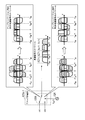
- FIG. 9 is a diagram for explaining the effect obtained by the present invention.
- FIG. 9 shows experimental results before and after applying the technique of the present invention in polarization-multiplexing 120 GBd-QPSK.
- FIG. 9A is a diagram showing an experimental result before applying the technique of the present invention in polarization multiplexing 120 GBd-QPSK
- FIG. 9B is a diagram showing an experimental result after applying the technique of the present invention. Is.
- FIGS. 9(A) and 9(B) after applying the technique of the present invention, the influence of interference is obviously reduced as compared with before applying the technique of the present invention. Recognize.
- the crosstalk component between the sub-bands caused by the imperfections between the devices can be removed.
- the transfer function estimator 25 calculates the transfer function using the high-speed signal output from the high-speed signal compensator 23 and the reference signal.
- the high-speed signal compensator 15 performs a calculation for compensating the high-speed signals (XI, XQ, YI, YQ) output by the transmission signal generator 14 in advance based on the calculated transfer function.
- the high speed signal compensating unit 23 performs a calculation for compensating for the high speed signals (XI, XQ, YI, YQ) output by the transmission signal generating unit 14 based on the calculated transfer function.
- a transfer function for compensating for the frequency characteristic difference between the low speed signals and the high speed signals generated in the high speed signal generators 12-1 to 12-4 and the optical modulator 13 of the optical transmitter 10 and the incompleteness of the analog device are obtained. It can be calculated. Therefore, it is possible to improve the deterioration of the signal quality by performing compensation using the calculated transfer function.
- the divided spectrums are rearranged by the frequency shift units 151-1 to 151-3 in the high speed signal compensating unit 15 and the frequency shift units 231-1 to 231-3 in the high speed signal compensating unit 23. .. This makes it possible to collect crosstalk components between bands caused by imperfections of the device.
- a polarization multiplexed signal is targeted, but a single polarization signal may be used.
- the IQ modulation signal is targeted in the configuration of the above-described embodiment, it may be an intensity modulation signal.
- the optical modulator 13 is not the polarization multiplexing type Mach-Zehnder type vector modulator described above but an intensity modulator.
- a type or a type using a direct modulation light source for the laser module is applied.
- QPSK or 16QAM symbol points are applied as the symbol points assigned by the bit mapping unit 141, but modulation formats other than these may be applied.
- the technique of the present invention is applied to the analog multiplexing system (AMUX (Analogue Multiplexer)) shown in Non-Patent Document 3 has been described as an example, but the present invention is not limited to this.
- the technique of the present invention may be applied to the analog multiplexing system (band doubler (type 1)) shown in Non-Patent Document 1 or the analog multiplexing system (band doubler (type 2)) shown in Non-Patent Document 4. You may.
- the configuration when the technique of the present invention is applied to another analog multiplex system will be specifically described below.
- FIG. 10 is a diagram showing an example of low-speed signal generation in the low-speed signal generation unit 16 when the technique of the present invention is applied to the analog multiplexing method shown in Non-Patent Document 1.
- 10A shows the spectrum of the high-speed signal S(f) input to the low-speed signal generator 16
- FIG. 10B shows the spectrum of the first low-speed signal generated by the low-speed signal generator 16.
- 10C shows the spectrum of the second low speed signal generated by the low speed signal generator 16.
- the low-speed signal generation unit 16 generates a first low-speed signal obtained by frequency-shifting and adding the spectrum of the high-speed signal and a second low-speed signal obtained by frequency-shifting and subtracting the spectrum of the high-speed signal.
- FIG. 11 is a diagram showing an internal configuration of the analog multiplexing unit 123a-1 when the technique of the present invention is applied to the analog multiplexing method shown in Non-Patent Document 1. Note that, although the configuration of the analog multiplexing unit 123a-1 is described as an example in FIG. 11, the analog multiplexing units 123a-2 to 123a-4 also have the same configuration.
- the analog multiplexing unit 123a-1 includes a high speed switching circuit 1235.
- the high speed switching circuit 1235 has ch1 and ch2 as input terminals.
- An analog signal (low speed signal) output from the DAC 121-1 is input to ch1, and an analog signal (low speed signal) output from the DAC 122-1 is input to ch2.
- the analog signal input to the high speed switching circuit 1235 is modulated by the clock generated by the clock generator 126 that outputs a clock of a predetermined frequency (for example, f UB ).
- the high-speed switching 1235 can be represented as an equivalent circuit by multiplying 1+1/r ⁇ cos(wt) on the ch1 side and 1-1/r ⁇ cos(wt) on the ch2 side.
- the signals after modulation (after up-conversion) are added, and the spectral components with inverted polarities in the spectra of the first and second low-speed signals after up-conversion are canceled and only the spectral components with the same polarity remain, leaving the high-speed signal. Will be rebuilt. Further, the spectrum outside the band generated after the combination may be removed by an electric or optical analog filter. If the device has imperfections, the above cancellation will be imperfect, so when the spectrum of the high-speed signal is decomposed into four subbands and considered, crosstalk components between the subbands are reconstructed. It remains. In the present invention, crosstalk between subbands is removed by rearranging the divided spectra in the high speed signal compensating unit 15 and the high speed signal compensating unit 23.
- FIG. 12 is a diagram showing an example of low-speed signal generation in the low-speed signal generation unit 16 when the technique of the present invention is applied to the analog multiplexing method shown in Non-Patent Document 4.
- 12A shows the spectrum of the high-speed signal S(f) input to the low-speed signal generator 16
- FIG. 12B shows the spectrum of the first low-speed signal generated by the low-speed signal generator 16.
- 12C shows the spectrum of the second low speed signal generated by the low speed signal generator 16.
- the low-speed signal generation unit 16 generates a first low-speed signal obtained by frequency-shifting and adding the spectrum of the high-speed signal and a second low-speed signal obtained by frequency-shifting and subtracting the spectrum of the high-speed signal.
- FIG. 13 is a diagram showing an internal configuration of the analog multiplexing unit 123a-1 when the technique of the present invention is applied to the analog multiplexing method shown in Non-Patent Document 4.
- the configuration of the analog multiplexing unit 123a-1 will be described as an example, but the analog multiplexing units 123a-2 to 123a-4 also have the same configuration.
- the internal configuration of the analog multiplexing unit 123a-1 is the same as that of the analog multiplexing unit 123a-1 shown in FIG.
- the difference from the analog multiplexing unit 123a-1 shown in FIG. 11 is that the analog signal input to the high-speed switching circuit 1235 is generated by the clock generator 124 that outputs a clock of a predetermined frequency (for example, f UB /2).
- the analog signal input to the high-speed switching circuit 1235 is modulated with the clock generated by the clock generator 124 that outputs the clock of the predetermined frequency (for example, f UB /2).
- the high-speed switching 1235 can be represented as an equivalent circuit by multiplying 1+1/r ⁇ cos(wt) on the ch1 side and 1-1/r ⁇ cos(wt) on the ch2 side.
- the signals after modulation (after up-conversion) are added, and the spectral components with inverted polarities in the spectra of the first and second low-speed signals after up-conversion are canceled and only the spectral components with the same polarity remain, leaving the high-speed signal. Will be rebuilt. Further, the spectrum outside the band generated after the combination may be removed by an electric or optical analog filter. If the device has imperfections, the above cancellation will be imperfect, so when the spectrum of the high-speed signal is decomposed into four subbands and considered, crosstalk components between the subbands are reconstructed. It remains. In the present invention, crosstalk between subbands is removed by rearranging the divided spectra in the high speed signal compensating unit 15 and the high speed signal compensating unit 23.
- the optical transmitter 10 and the optical receiver 20 described above may be realized by a computer.
- the program for realizing this function may be recorded in a computer-readable recording medium, and the program recorded in this recording medium may be read by a computer system and executed.
- the “computer system” mentioned here includes an OS and hardware such as peripheral devices.
- the “computer-readable recording medium” refers to a portable medium such as a flexible disk, a magneto-optical disk, a ROM, a CD-ROM, or a storage device such as a hard disk built in a computer system.
- the "computer-readable recording medium” means to hold a program dynamically for a short time like a communication line when transmitting the program through a network such as the Internet or a communication line such as a telephone line.
- a volatile memory inside a computer system that serves as a server or a client in that case may hold a program for a certain period of time.
- the program may be for realizing some of the functions described above, or may be one that can realize the functions described above in combination with a program already recorded in the computer system, It may be realized using a programmable logic device such as FPGA (Field Programmable Gate Array).
- optical demodulation unit 22... transmission line compensation unit, 23... high speed signal compensation unit, 231-1 to 231-3... frequency shift unit, 232... high speed signal equalization unit, 233-1 to 233-4... Multiplier, 234... Adder, 24... Received data demodulation section, 25... Transfer function estimation section, 26... Optical receiving section, 27-1 to 27-4... ADC
Abstract
Provided is an optical transmission system comprising an optical transmission device and an optical receiving device. The optical transmission device comprises: a low-speed signal generation unit which generates a plurality of low-speed signals on the basis of a transmission data series input signal and a signal in which the spectrum of the input signal is cyclically shifted; a high-speed signal generation unit which generates high-speed signals by digital-analog converting and compositing the plurality of low-speed signals; and an optical modulation unit which transmits to a transmission path an optical signal in which the high-speed signals are modulated. The optical receiving device comprises: a receiving unit which receives the optical signal from the optical path and outputs the high-speed signals obtained from the received optical signal; an optical receiving device-side high-speed signal compensation unit with which the high-speed signals are compensated on the basis of the high-speed signals outputted by the receiving unit and a signal in which the spectra of the high-speed signals are cyclically shifted; and a received data decoding unit which restores binary information which is included in the optical signal transmitted by the optical transmission device by decoding the high-speed signals the compensation of which is carried out by the optical receiving device-side high-speed signal compensation unit.
Description
本発明は、光伝送システム、光送信機、光受信機及び伝達関数推定方法に関する。
The present invention relates to an optical transmission system, an optical transmitter, an optical receiver, and a transfer function estimation method.
光通信システムの基幹網において、近年の通信トラヒックの拡大と、400Gbps(Gigabits per second)や1Tbps(Terabits per second)のEthernet(登録商標)をはじめとするクライアント信号を収容する回線の容量増加により、1チャネルあたりの伝送容量の拡大が求められている。現在の1チャネルあたり100Gbpsを有するシステムでは、変調速度が32GBaud(Baud)であり、変調方式としてDP-QPSK(Dual Polarization-Quadrature Phase Shift Keying)を用いるデジタルコヒーレント光伝送方式が採用されている。
In the backbone network of optical communication systems, due to the expansion of communication traffic in recent years and the increase in the capacity of lines that accommodate client signals such as 400 Gbps (Gigabits per second) and 1 Tbps (Terabits per second) Ethernet (registered trademark), It is required to increase the transmission capacity per channel. In the current system having 100 Gbps per channel, the modulation speed is 32 GBaud (Baud), and the digital coherent optical transmission method using DP-QPSK (Dual Polarization-Quadrature Phase Shift Keying) is adopted as the modulation method.
1チャネルあたりの伝送容量拡大に向け、次世代の400Gbps、1Tbps級の伝送では、変調速度の向上が検討されている。変調速度を向上させる上でDAC(Digital to Analog Converter)のアナログ帯域の制限が課題となる。DACのアナログ帯域を拡大する技術として、複数のデジタルアナログコンバータ(DAC)とアナログ多重部を用いて複数の低速信号をアナログ的に合成することによって高速信号を生成する技術が提案されている(例えば、非特許文献1~3参照)。このような技術では、アナログ的に信号を多重するため、アナログ回路の不完全性が、生成される高速信号の品質に大きな影響を与える。そのため、光送信機の不完全性の推定・補償技術が重要となる。
-In order to expand the transmission capacity per channel, in the next-generation 400 Gbps, 1 Tbps class transmission, improvement of the modulation speed is being considered. Limiting the analog band of the DAC (Digital to Analog Converter) is an issue for improving the modulation speed. As a technique of expanding the analog band of the DAC, a technique of generating a high-speed signal by analog-synthesizing a plurality of low-speed signals using a plurality of digital-analog converters (DAC) and an analog multiplexer has been proposed (for example, , Non-Patent Documents 1 to 3). In such a technique, since signals are multiplexed in an analog manner, imperfections in the analog circuit have a great influence on the quality of the generated high-speed signal. Therefore, the technique of estimating and compensating the imperfections of the optical transmitter is important.
上記のようなアナログ回路の不完全性を補償するための技術として、特許文献1及び非特許文献に示す技術が提案されている。
特許文献1に開示された技術では、光送信機又は光受信機において、上記の技術によって生成された高速信号を複数の低速信号に再分離することで、低速信号における伝達関数を推定し、推定した伝達関数を用いて伝達関数を更新する。
非特許文献4に開示された技術では、低速信号における伝達関数と、高速信号における伝達関数とを同時に補償可能なデジタルフィルタを用いている。 As a technique for compensating the imperfections of the analog circuit as described above, the techniques shown inPatent Document 1 and Non-Patent Document have been proposed.
In the technique disclosed inPatent Document 1, an optical transmitter or an optical receiver re-separates a high-speed signal generated by the above technique into a plurality of low-speed signals, thereby estimating and estimating a transfer function in the low-speed signal. The transfer function is updated using the transfer function.
The technique disclosed in Non-PatentDocument 4 uses a digital filter capable of simultaneously compensating for a transfer function for a low speed signal and a transfer function for a high speed signal.
特許文献1に開示された技術では、光送信機又は光受信機において、上記の技術によって生成された高速信号を複数の低速信号に再分離することで、低速信号における伝達関数を推定し、推定した伝達関数を用いて伝達関数を更新する。
非特許文献4に開示された技術では、低速信号における伝達関数と、高速信号における伝達関数とを同時に補償可能なデジタルフィルタを用いている。 As a technique for compensating the imperfections of the analog circuit as described above, the techniques shown in
In the technique disclosed in
The technique disclosed in Non-Patent
しかしながら、従来のようにアナログ多重部を用いて複数の低速信号をアナログ的に合成して高速信号を生成する場合、アナログ回路の不完全性により低速信号間のクロストーク成分が残留してしまう。これにより、信号品質が劣化してしまうという問題があった。
However, when a plurality of low-speed signals are combined in an analog manner to generate a high-speed signal as in the conventional case, a crosstalk component between the low-speed signals remains due to imperfections in the analog circuit. As a result, there is a problem that the signal quality is deteriorated.
上記事情に鑑み、本発明は、信号品質の劣化を改善することができる技術の提供を目的としている。
In view of the above circumstances, the present invention aims to provide a technique capable of improving deterioration of signal quality.
本発明の一態様は、光送信機と、光受信機とを備える光伝送システムであって、前記光送信機は、送信データ系列の入力信号と、前記入力信号のスペクトルを巡回シフトした信号とに基づいて複数の低速信号を生成する低速信号生成部と、前記複数の低速信号をデジタルアナログ変換して、合成することにより高速信号を生成する高速信号生成部と、前記高速信号を変調した光信号を伝送路に送信する光変調部と、を備え、前記光受信機は、前記伝送路から前記光信号を受信し、受信する前記光信号から得られる前記高速信号を出力する受信部と、前記受信部が出力する前記高速信号と、前記高速信号のスペクトルを巡回シフトした信号とに基づいて前記高速信号を補償する光受信機側高速信号補償部と、前記光受信機側高速信号補償部により補償がなされた前記高速信号を復号することによって前記光送信機が送信した前記光信号に含まれるバイナリ情報を復元する受信データ復号部と、を備える光伝送システムである。
One aspect of the present invention is an optical transmission system including an optical transmitter and an optical receiver, wherein the optical transmitter includes an input signal of a transmission data sequence and a signal obtained by cyclically shifting a spectrum of the input signal. A low-speed signal generation unit that generates a plurality of low-speed signals based on the above, a high-speed signal generation unit that generates a high-speed signal by performing digital-analog conversion of the plurality of low-speed signals and combining, and a high-speed signal modulated light An optical modulator for transmitting a signal to a transmission path, wherein the optical receiver receives the optical signal from the transmission path, and a receiver for outputting the high-speed signal obtained from the received optical signal, An optical receiver-side high-speed signal compensator for compensating the high-speed signal based on the high-speed signal output from the receiver and a signal obtained by cyclically shifting the spectrum of the high-speed signal, and the optical receiver-side high-speed signal compensator An optical transmission system, comprising: a reception data decoding unit that restores binary information included in the optical signal transmitted by the optical transmitter by decoding the high-speed signal compensated by.
本発明の一態様は、光伝送システムであって、前記光送信機は、送信データ系列の入力信号と、前記入力信号のスペクトルを巡回シフトした信号とのそれぞれに対して伝達関数を乗算し、乗算結果を加算することにより前記入力信号を補償する送信機側高速信号補償部をさらに備え、前記低速信号生成部は、前記送信機側高速信号補償部により補償がなされた前記入力信号から前記複数の低速信号を生成し、前記光受信機側高速信号補償部は、前記受信部が出力する前記高速信号と、前記高速信号のスペクトルを巡回シフトした信号とのそれぞれに対して伝達関数を乗算し、乗算結果を加算することにより前記高速信号を補償する。
One aspect of the present invention is an optical transmission system, wherein the optical transmitter multiplies an input signal of a transmission data sequence and a signal obtained by cyclically shifting the spectrum of the input signal by a transfer function, The transmitter-side high-speed signal compensator for compensating the input signal by adding multiplication results is further provided, and the low-speed signal generator includes the plurality of the input signals compensated by the transmitter-side high-speed signal compensator. And the optical receiver side high speed signal compensator multiplies each of the high speed signal output by the receiver and the signal obtained by cyclically shifting the spectrum of the high speed signal by a transfer function. , The high speed signal is compensated by adding the multiplication results.
本発明の一態様は、光伝送システムであって、前記低速信号生成部は、送信データ系列の入力信号と、前記入力信号のスペクトルを巡回シフトした信号とのそれぞれに対して伝達関数を乗算し、乗算結果を加算することにより前記入力信号を補償するとともに、補償した前記入力信号から前記複数の低速信号を生成し、前記光受信機側高速信号補償部は、前記受信部が出力する前記高速信号と、前記高速信号のスペクトルを巡回シフトした信号とのそれぞれに対して伝達関数を乗算し、乗算結果を加算することにより前記高速信号を補償する。
One aspect of the present invention is an optical transmission system, wherein the low-speed signal generation unit multiplies each of an input signal of a transmission data sequence and a signal obtained by cyclically shifting the spectrum of the input signal by a transfer function. , The plurality of low speed signals are generated from the compensated input signals by adding the multiplication results, and the optical receiver side high speed signal compensating unit outputs the high speed signals output from the receiving unit. The high-speed signal is compensated by multiplying each of the signal and the signal obtained by cyclically shifting the spectrum of the high-speed signal by the transfer function and adding the multiplication results.
本発明の一態様は、光伝送システムであって、前記光受信機は、前記光受信機側高速信号補償部の出力信号と、参照信号との差分に基づいて、前記伝達関数を算出する伝達関数推定部をさらに備える。
One aspect of the present invention is an optical transmission system, wherein the optical receiver calculates a transfer function based on a difference between an output signal of the optical receiver-side high-speed signal compensator and a reference signal. The function estimating unit is further provided.
本発明の一態様は、光伝送システムであって、前記伝達関数推定部は、予め既知信号として定められている前記送信データ系列の一部を前記参照信号として前記伝達関数を算出するか、又は、前記光受信機側高速信号補償部の出力を硬判定した値を前記参照信号として前記伝達関数を算出する。
One aspect of the present invention is an optical transmission system, wherein the transfer function estimation unit calculates the transfer function by using a part of the transmission data sequence that is predetermined as a known signal as the reference signal, or The transfer function is calculated by using the hard-decision value of the output of the high-speed signal compensator on the optical receiver side as the reference signal.
本発明の一態様は、光送信機と、光受信機とを備える光伝送システムにおける光送信機であって、送信データ系列の入力信号と、前記入力信号のスペクトルを巡回シフトした信号とに基づいて複数の低速信号を生成する低速信号生成部と、前記複数の低速信号をデジタルアナログ変換して、合成することにより高速信号を生成する高速信号生成部と、前記高速信号を変調した光信号を伝送路に送信する光変調部と、を備える光送信機である。
One aspect of the present invention is an optical transmitter in an optical transmission system including an optical transmitter and an optical receiver, which is based on an input signal of a transmission data sequence and a signal obtained by cyclically shifting a spectrum of the input signal. A low-speed signal generation unit that generates a plurality of low-speed signals, a high-speed signal generation unit that digital-analog converts the plurality of low-speed signals to generate a high-speed signal, and an optical signal that modulates the high-speed signal. An optical transmitter including: an optical modulator that transmits to a transmission path.
本発明の一態様は、光送信機と、光受信機とを備える光伝送システムにおける光受信機であって、前記光送信機から送信された光信号を伝送路を介して受信し、受信する前記光信号から得られる高速信号を出力する受信部と、前記受信部が出力する前記高速信号と、前記高速信号のスペクトルを巡回シフトした信号とに基づいて前記高速信号を補償する高速信号補償部と、前記光受信機側高速信号補償部により補償がなされた前記高速信号を復号することによって前記光送信機が送信した前記光信号に含まれるバイナリ情報を復元する受信データ復号部と、を備える光受信機である。
One aspect of the present invention is an optical receiver in an optical transmission system including an optical transmitter and an optical receiver, and receives an optical signal transmitted from the optical transmitter via a transmission path and receives the optical signal. A receiver that outputs a high-speed signal obtained from the optical signal, a high-speed signal compensator that compensates the high-speed signal based on the high-speed signal output by the receiver and a signal obtained by cyclically shifting the spectrum of the high-speed signal. And a received data decoding unit that restores the binary information contained in the optical signal transmitted by the optical transmitter by decoding the high speed signal compensated by the optical receiver side high speed signal compensating unit. It is an optical receiver.
本発明の一態様は、光送信機と、光受信機とを備える光伝送システムにおける伝達関数推定方法であって、前記光送信機が、送信データ系列の入力信号と、前記入力信号のスペクトルを巡回シフトした信号とに基づいて複数の低速信号を生成する低速信号生成ステップと、前記複数の低速信号をデジタルアナログ変換して、合成することにより高速信号を生成する高速信号生成ステップと、前記高速信号を変調した光信号を伝送路に送信する光変調ステップと、を有し、前記光受信機が、前記伝送路から前記光信号を受信し、受信する前記光信号から得られる前記高速信号を出力する受信ステップと、前記受信ステップにおいて出力される前記高速信号と、前記高速信号のスペクトルを巡回シフトした信号とに基づいて前記高速信号を補償する光受信機側高速信号補償ステップと、前記光受信機側高速信号補償ステップにより補償がなされた前記高速信号を復号することによって前記光送信機が送信した前記光信号に含まれるバイナリ情報を復元する受信データ復号ステップと、を有する伝達関数推定方法である。
One aspect of the present invention is a transfer function estimation method in an optical transmission system including an optical transmitter and an optical receiver, wherein the optical transmitter outputs an input signal of a transmission data sequence and a spectrum of the input signal. A low-speed signal generation step of generating a plurality of low-speed signals based on the cyclically-shifted signal; a high-speed signal generation step of digital-analog converting the plurality of low-speed signals to generate a high-speed signal, and the high-speed signal An optical modulation step of transmitting an optical signal obtained by modulating a signal to a transmission line, wherein the optical receiver receives the optical signal from the transmission line, and receives the high-speed signal obtained from the received optical signal. An optical receiver-side high-speed signal compensating step for compensating the high-speed signal based on a receiving step of outputting, the high-speed signal output in the receiving step, and a signal obtained by cyclically shifting the spectrum of the high-speed signal, A received data decoding step of recovering binary information contained in the optical signal transmitted by the optical transmitter by decoding the high speed signal compensated by the receiver side high speed signal compensation step; Is.
本発明により、信号品質の劣化を改善することが可能となる。
The present invention makes it possible to improve the deterioration of signal quality.
以下、本発明の一実施形態を、図面を参照しながら説明する。
図1は、本発明における光伝送システム100の構成を示すブロック図である。
光伝送システム100は、光送信機10及び光受信機20を備える。光送信機10と光受信機20は、伝送路30を介して接続される。また、光送信機10と光受信機20は、通信回線40を介して接続される。 An embodiment of the present invention will be described below with reference to the drawings.
FIG. 1 is a block diagram showing the configuration of anoptical transmission system 100 according to the present invention.
Theoptical transmission system 100 includes an optical transmitter 10 and an optical receiver 20. The optical transmitter 10 and the optical receiver 20 are connected via a transmission line 30. Further, the optical transmitter 10 and the optical receiver 20 are connected via a communication line 40.
図1は、本発明における光伝送システム100の構成を示すブロック図である。
光伝送システム100は、光送信機10及び光受信機20を備える。光送信機10と光受信機20は、伝送路30を介して接続される。また、光送信機10と光受信機20は、通信回線40を介して接続される。 An embodiment of the present invention will be described below with reference to the drawings.
FIG. 1 is a block diagram showing the configuration of an
The
伝送路30は、光送信機10から送信された光信号を光受信機20に伝送する経路である。伝送路30は、光ファイバ30-1と光増幅器30-2とで構成される。光送信機10から出力される光信号は、光ファイバ30-1により伝送され、光増幅器30-2により増幅されて、光受信機20が受信する。
The transmission path 30 is a path for transmitting the optical signal transmitted from the optical transmitter 10 to the optical receiver 20. The transmission line 30 is composed of an optical fiber 30-1 and an optical amplifier 30-2. The optical signal output from the optical transmitter 10 is transmitted by the optical fiber 30-1, amplified by the optical amplifier 30-2, and received by the optical receiver 20.
通信回線5は、光受信機20によって算出された伝達関数が光送信機10に送信される際に用いられる。通信回線5は、例えば、コミュニケーションチャネルやNE-Ops(Network Element Operation System)やNW-Ops(Network Operation System)等の制御チャネルである。
The communication line 5 is used when the transfer function calculated by the optical receiver 20 is transmitted to the optical transmitter 10. The communication line 5 is, for example, a communication channel or a control channel such as NE-Ops (Network Element Operation System) or NW-Ops (Network Operation System).
次に、光送信機10及び光受信機20の具体的な構成について説明する。
光送信機10は、デジタル信号処理部11、高速信号生成部12及び光変調部13を備える。なお、以下の記載において、低速信号及び高速信号の用語における低速と高速の意味は、アナログ帯域の帯域幅の狭さと広さを示す。例えば、高速信号の帯域幅がfc[GHz]である場合、低速信号の帯域幅はfc[GHz]より小さい値となる。本実施形態では、高速信号≒低速信号×N(Nは整数でDAC(Digital-to-Analog Converter)の個数)程度の帯域幅とする。 Next, specific configurations of theoptical transmitter 10 and the optical receiver 20 will be described.
Theoptical transmitter 10 includes a digital signal processing unit 11, a high speed signal generation unit 12, and an optical modulation unit 13. In the following description, the terms low speed and high speed in the terms low speed signal and high speed signal indicate the narrowness and width of the analog bandwidth. For example, when the bandwidth of the high speed signal is fc [GHz], the bandwidth of the low speed signal is a value smaller than fc [GHz]. In this embodiment, the bandwidth is about high-speed signal≈low-speed signal×N (N is an integer and the number of DACs (Digital-to-Analog Converters)).
光送信機10は、デジタル信号処理部11、高速信号生成部12及び光変調部13を備える。なお、以下の記載において、低速信号及び高速信号の用語における低速と高速の意味は、アナログ帯域の帯域幅の狭さと広さを示す。例えば、高速信号の帯域幅がfc[GHz]である場合、低速信号の帯域幅はfc[GHz]より小さい値となる。本実施形態では、高速信号≒低速信号×N(Nは整数でDAC(Digital-to-Analog Converter)の個数)程度の帯域幅とする。 Next, specific configurations of the
The
デジタル信号処理部11は、外部から供給されるバイナリ情報である送信データ系列に対してデジタル信号処理を行う。デジタル信号処理部11は、送信信号生成部14、高速信号補償部15及び低速信号生成部16を備える。
送信信号生成部14は、高速信号である変調信号系列(XI,XQ,YI,YQ)を生成する。具体的には、送信信号生成部14は、図2に示す内部構成を有しており、ビットマッピング部141及び波形整形部142を備える。ビットマッピング部141は、送信データ系列に対して、QPSK(Quadrature Phase Shift Keying)や16QAM(Quadrature Amplitude Modulation)等のシンボル点に対する送信ビットの割り当てを行い、高速信号である変調信号系列(XI,XQ,YI,YQ)を生成する。 The digitalsignal processing unit 11 performs digital signal processing on a transmission data sequence that is binary information supplied from the outside. The digital signal processing unit 11 includes a transmission signal generation unit 14, a high speed signal compensation unit 15, and a low speed signal generation unit 16.
Thetransmission signal generator 14 generates a modulated signal sequence (XI, XQ, YI, YQ) which is a high speed signal. Specifically, the transmission signal generation unit 14 has the internal configuration shown in FIG. 2 and includes a bit mapping unit 141 and a waveform shaping unit 142. The bit mapping unit 141 allocates transmission bits to symbol points such as QPSK (Quadrature Phase Shift Keying) and 16QAM (Quadrature Amplitude Modulation) for the transmission data series, and the modulated signal series (XI, XQ) that are high-speed signals. , YI, YQ) is generated.
送信信号生成部14は、高速信号である変調信号系列(XI,XQ,YI,YQ)を生成する。具体的には、送信信号生成部14は、図2に示す内部構成を有しており、ビットマッピング部141及び波形整形部142を備える。ビットマッピング部141は、送信データ系列に対して、QPSK(Quadrature Phase Shift Keying)や16QAM(Quadrature Amplitude Modulation)等のシンボル点に対する送信ビットの割り当てを行い、高速信号である変調信号系列(XI,XQ,YI,YQ)を生成する。 The digital
The
波形整形部142は、ビットマッピング部141が出力する変調信号系列(XI,XQ,YI,YQ)それぞれに対してフィルタリング処理を行う。フィルタリング処理には、Raised Cosine FilterやRoot Raised Cosine Filter等のフィルタが用いられる。なお、波形整形部142において、伝送路での波形歪を補償する前置波長分散補償や前置非線形光学効果補償等の任意の信号処理を行うようにしてもよい。
The waveform shaping unit 142 performs a filtering process on each of the modulated signal sequences (XI, XQ, YI, YQ) output by the bit mapping unit 141. Filters such as Raised Cosine Filter and Root Raised Cosine Filter are used for the filtering process. The waveform shaping section 142 may perform arbitrary signal processing such as pre-chromatic dispersion compensation for compensating for waveform distortion on the transmission path or pre-linear nonlinear effect compensation.
高速信号補償部15は、波形整形がなされた変調信号系列(XI,XQ,YI,YQ)と、光受信機20から得られる伝達関数とに基づいて周波数特性の補償を行う。ここで、伝達関数に基づく周波数特性の補償の方式としては、任意の方式を適用することができ、例えば、FIR(Finite Impulse Response)フィルタやIIR(Infinite Impulse Response)フィルタ、離散フーリエ変換を用いた周波数領域での等化器等を使ったデジタル信号処理方式、または、位相器や遅延線等のアナログフィルタを用いたアナログ方式が適用される。高速信号補償部15は、波形整形がなされた変調信号系列(XI,XQ,YI,YQ)毎に周波数特性の補償を行う。なお、高速信号補償部15において、伝送路での波形歪を補償する前置波長分散補償や前置非線形光学効果補償等の任意の信号処理を行うようにしてもよい。
The high-speed signal compensating unit 15 compensates the frequency characteristic based on the modulated signal series (XI, XQ, YI, YQ) whose waveform has been shaped and the transfer function obtained from the optical receiver 20. Here, as a method for compensating the frequency characteristic based on the transfer function, any method can be applied, and for example, an FIR (Finite Impulse Response) filter, an IIR (Infinite Impulse Response) filter, or a discrete Fourier transform is used. A digital signal processing method using an equalizer in the frequency domain or an analog method using an analog filter such as a phase shifter or a delay line is applied. The high-speed signal compensator 15 compensates the frequency characteristic for each modulated signal series (XI, XQ, YI, YQ) whose waveform has been shaped. Note that the high-speed signal compensator 15 may perform arbitrary signal processing such as pre-chromatic dispersion compensation for compensating for waveform distortion on the transmission path or pre-linear optical effect compensation.
具体的には、高速信号補償部15は、図3に示す内部構成を有しており、複数の周波数シフト部151-1~151-3及び高速信号等化部152を備える。
なお、図3では、一例として波形整形部142が出力する1レーンの高速信号(XI)を例に示して説明するが、高速信号補償部15は波形整形部142が出力する4レーンの高速信号(XI,XQ,YI,YQ)それぞれに対して同様の処理を行う。 Specifically, the highspeed signal compensator 15 has the internal configuration shown in FIG. 3, and includes a plurality of frequency shifters 151-1 to 151-3 and a high speed signal equalizer 152.
In FIG. 3, the one-lane high-speed signal (XI) output by thewaveform shaping unit 142 is described as an example, but the high-speed signal compensating unit 15 outputs the four-lane high-speed signal output by the waveform shaping unit 142. Similar processing is performed for each of (XI, XQ, YI, YQ).
なお、図3では、一例として波形整形部142が出力する1レーンの高速信号(XI)を例に示して説明するが、高速信号補償部15は波形整形部142が出力する4レーンの高速信号(XI,XQ,YI,YQ)それぞれに対して同様の処理を行う。 Specifically, the high
In FIG. 3, the one-lane high-speed signal (XI) output by the
周波数シフト部151-1~151-3は、入力された変調信号系列のスペクトルを周波数的に巡回シフトする。具体的には、周波数シフト部151-1は、入力された変調信号系列のスペクトルを左に1つ分シフトする。周波数シフト部151-2は、入力された変調信号系列のスペクトルを左に2つ分シフトする。周波数シフト部151-3は、入力された変調信号系列のスペクトルを左に3つ分シフトする。帯域間クロストークが生じる場合には、分割されたスペクトルが各帯域に存在していることで補償が可能となる。そのため巡回シフトの個数は、分割されるスペクトルの個数に依存する。図3では、分割数N=2の場合を記載しており、巡回シフトの個数は、M=N×2で表される。
The frequency shift units 151-1 to 151-3 cyclically shift the spectrum of the input modulation signal sequence in frequency. Specifically, the frequency shifter 151-1 shifts the spectrum of the input modulated signal sequence by one to the left. The frequency shifter 151-2 shifts the spectrum of the input modulated signal sequence by two to the left. The frequency shifter 151-3 shifts the spectrum of the input modulation signal sequence by three to the left. When crosstalk between bands occurs, it is possible to compensate because the divided spectrum exists in each band. Therefore, the number of cyclic shifts depends on the number of divided spectra. FIG. 3 shows the case where the number of divisions N=2, and the number of cyclic shifts is represented by M=N×2.
本発明は、分割後のスペクトルを周波数軸上で並びかえて、分割後の各スペクトル成分が、全ての周波数帯域に出現するように処理を行う。この処理の1つの実現方法が、周波数シフト部151-1~151-3が行う「巡回シフト」である。
The present invention rearranges the divided spectrums on the frequency axis and performs processing so that each spectrum component after division appears in all frequency bands. One method of realizing this processing is “cyclic shift” performed by the frequency shift units 151-1 to 151-3.
図3に示すように、入力された変調信号系列の高速信号をR0(f)とし、周波数シフト部151-1により高速信号R0(f)のスペクトルがシフトされた高速信号をR1(f)とし、周波数シフト部151-2により高速信号R0(f)のスペクトルがシフトされた高速信号をR2(f)とし、周波数シフト部151-3により高速信号R0(f)のスペクトルがシフトされた高速信号をR3(f)とする。
As shown in FIG. 3, the high-speed signal of the input modulated signal sequence is R 0 (f), and the high-speed signal in which the spectrum of the high-speed signal R 0 (f) is shifted by the frequency shifter 151-1 is R 1 ( f), the high speed signal R 0 (f) obtained by shifting the spectrum of the high speed signal R 0 (f) by the frequency shift unit 151-2 is defined as R 2 (f), and the spectrum of the high speed signal R 0 (f) by the frequency shift unit 151-3. Let the high-speed signal shifted by R 3 (f).
高速信号等化部152は、入力された複数の高速信号(R0(f),R1(f),R2(f),R3(f))それぞれに対して伝達関数(A0(f),A1(f),A2(f),A3(f))を乗算し、乗算結果を加算して高速信号を補償する。高速信号等化部152は、複数の乗算器153-1~153-4及び加算器154を備える。
The high-speed signal equalization unit 152 receives the transfer function (A 0 (A 0 (f 0 )) for each of the input high-speed signals (R 0 (f), R 1 (f), R 2 (f), R 3 (f)). f), A 1 (f), A 2 (f), A 3 (f)) are multiplied and the multiplication results are added to compensate for the high speed signal. The high speed signal equalizer 152 includes a plurality of multipliers 153-1 to 153-4 and an adder 154.
乗算器153-1~153-4は、入力された高速信号に対して伝達関数を乗算する。
具体的には、乗算器153-1には波形整形部142から出力された変調信号系列の高速信号R0(f)がそのまま入力され、乗算器153-2には周波数シフト部151-1によって周波数的に巡回シフトされた高速信号R1(f)が入力され、乗算器153-3には周波数シフト部151-2によって周波数的に巡回シフトされた高速信号R2(f)が入力され、乗算器153-4には周波数シフト部151-3によって周波数的に巡回シフトされた高速信号R3(f)が入力される。また、乗算器153-1~153-4に入力される伝達関数A0(f),A1(f),A2(f),A3(f)は、光受信機20によって算出される。 The multipliers 153-1 to 153-4 multiply the input high speed signal by the transfer function.
Specifically, the multiplier 153-1 receives the high-speed signal R 0 (f) of the modulated signal sequence output from thewaveform shaping unit 142 as it is, and the multiplier 153-2 uses the frequency shift unit 151-1. The high frequency signal R 1 (f) cyclically shifted in frequency is input, and the high speed signal R 2 (f) cyclically shifted in frequency by the frequency shifter 151-2 is input to the multiplier 153-3. The multiplier 153-4 receives the high-speed signal R 3 (f) cyclically shifted in frequency by the frequency shifter 151-3. The transfer functions A 0 (f), A 1 (f), A 2 (f) and A 3 (f) input to the multipliers 153-1 to 153-4 are calculated by the optical receiver 20. ..
具体的には、乗算器153-1には波形整形部142から出力された変調信号系列の高速信号R0(f)がそのまま入力され、乗算器153-2には周波数シフト部151-1によって周波数的に巡回シフトされた高速信号R1(f)が入力され、乗算器153-3には周波数シフト部151-2によって周波数的に巡回シフトされた高速信号R2(f)が入力され、乗算器153-4には周波数シフト部151-3によって周波数的に巡回シフトされた高速信号R3(f)が入力される。また、乗算器153-1~153-4に入力される伝達関数A0(f),A1(f),A2(f),A3(f)は、光受信機20によって算出される。 The multipliers 153-1 to 153-4 multiply the input high speed signal by the transfer function.
Specifically, the multiplier 153-1 receives the high-speed signal R 0 (f) of the modulated signal sequence output from the
乗算器153-1は、高速信号R0(f)と、伝達関数A0(f)とを乗算し、乗算結果を加算器154に出力する。乗算器153-2は、高速信号R1(f)と、伝達関数A1(f)とを乗算し、乗算結果を加算器154に出力する。乗算器153-3は、高速信号R2(f)と、伝達関数A2(f)とを乗算し、乗算結果を加算器154に出力する。
乗算器153-4は、高速信号R3(f)と、伝達関数A3(f)とを乗算し、乗算結果を加算器154に出力する。 The multiplier 153-1 multiplies the high-speed signal R 0 (f) by the transfer function A 0 (f), and outputs the multiplication result to theadder 154. The multiplier 153-2 multiplies the high-speed signal R 1 (f) by the transfer function A 1 (f) and outputs the multiplication result to the adder 154. The multiplier 153-3 multiplies the high-speed signal R 2 (f) by the transfer function A 2 (f), and outputs the multiplication result to the adder 154.
The multiplier 153-4 multiplies the high-speed signal R 3 (f) by the transfer function A 3 (f) and outputs the multiplication result to theadder 154.
乗算器153-4は、高速信号R3(f)と、伝達関数A3(f)とを乗算し、乗算結果を加算器154に出力する。 The multiplier 153-1 multiplies the high-speed signal R 0 (f) by the transfer function A 0 (f), and outputs the multiplication result to the
The multiplier 153-4 multiplies the high-speed signal R 3 (f) by the transfer function A 3 (f) and outputs the multiplication result to the
加算器154は、乗算器153-1~153-4それぞれから出力された乗算結果を加算する。これにより、高速信号S(f)が生成される。加算器154は、生成した高速信号S(f)を低速信号生成部16に出力する。なお、高速信号S(f)は以下の式(1)のように表される。
The adder 154 adds the multiplication results output from the multipliers 153-1 to 153-4. As a result, the high speed signal S(f) is generated. The adder 154 outputs the generated high speed signal S(f) to the low speed signal generator 16. The high speed signal S(f) is expressed by the following equation (1).

上述したように、高速信号補償部15は、入力した変調信号系列と、変調信号系列を周波数シフトした信号に対してそれぞれ伝達関数を畳み込み演算を行い、畳み込み演算結果を合計した信号を低速信号生成部16に出力する。
As described above, the high-speed signal compensating unit 15 performs the convolution operation of the transfer function on the input modulated signal sequence and the signal obtained by frequency-shifting the modulated signal sequence, and generates the low-speed signal of the sum of the convolution operation results. It is output to the unit 16.
低速信号生成部16は、高速信号補償部15から出力された高速信号S(f)を複数の低速信号に分解して高速信号生成部12-1~12-4に出力する。具体的には、低速信号生成部16は、出力する低速信号が高速信号生成部12-1~12-4により合成された際に、所望の信号が生成されるように信号処理を行って低速信号を生成する。低速信号の生成の手法としては、例えば、高速信号補償部15から出力された高速信号S(f)を周波数領域で分割し、高周波成分を折り返し、低周波成分と高周波成分を加算した信号と、低周波成分から高周波成分を減算した信号とをそれぞれ低速信号として生成する。なお、低速信号を生成する手法は、上記の手法に限られない。
The low-speed signal generator 16 decomposes the high-speed signal S(f) output from the high-speed signal compensator 15 into a plurality of low-speed signals, and outputs the low-speed signals to the high-speed signal generators 12-1 to 12-4. Specifically, the low-speed signal generation unit 16 performs signal processing so that a desired signal is generated when the low-speed signals to be output are combined by the high-speed signal generation units 12-1 to 12-4, and the low-speed signal generation unit 16 Generate a signal. As a method of generating the low-speed signal, for example, a signal obtained by dividing the high-speed signal S(f) output from the high-speed signal compensator 15 in the frequency domain, folding the high-frequency component, and adding the low-frequency component and the high-frequency component, A signal obtained by subtracting the high frequency component from the low frequency component is generated as a low speed signal. The method of generating the low-speed signal is not limited to the above method.
低速信号生成部16は、高速信号(XI,XQ,YI,YQ)の4つのレーン毎に、高速信号から複数の低速信号を生成する機能を有する。例えば、低速信号生成部16は、高速信号(XI)から複数の低速信号(XI1,XI2)を生成する。また、例えば、低速信号生成部16は、高速信号(XQ)から複数の低速信号(XQ1,XQ2)を生成する。また、例えば、低速信号生成部16は、高速信号(YI)から複数の低速信号(YI1,YI2)を生成する。また、例えば、低速信号生成部16は、高速信号(YQ)から複数の低速信号(YQ1,YQ2)を生成する。また、上記の低速信号生成部16が行う処理は、高速信号補償部15に入力される伝達関数A0~AM(Mは1以上の整数)の係数を用いることで、高速信号の補償と同時に実施しても良い。すなわち、高速信号補償部15と低速信号生成部16が1つの機能部として構成されてもよい。このように構成される場合、低速信号生成部16は、高速信号補償部15が備える機能を有する。すなわち、低速信号生成部16は、送信データ系列の入力信号と、入力信号のスペクトルを巡回シフトした信号とのそれぞれに対して伝達関数を乗算し、乗算結果を加算することにより入力信号を補償する。
The low speed signal generation unit 16 has a function of generating a plurality of low speed signals from the high speed signal for each of the four lanes of the high speed signal (XI, XQ, YI, YQ). For example, the low speed signal generation unit 16 generates a plurality of low speed signals (XI 1 , XI 2 ) from the high speed signal (XI). In addition, for example, the low speed signal generation unit 16 generates a plurality of low speed signals (XQ 1 , XQ 2 ) from the high speed signal (XQ). Further, for example, the low speed signal generation unit 16 generates a plurality of low speed signals (YI 1 , YI 2 ) from the high speed signal (YI). In addition, for example, the low speed signal generation unit 16 generates a plurality of low speed signals (YQ 1 , YQ 2 ) from the high speed signal (YQ). Further, the processing performed by the low-speed signal generation unit 16 described above uses high-speed signal compensation by using the coefficients of the transfer functions A 0 to A M (M is an integer of 1 or more) input to the high-speed signal compensation unit 15. You may carry out simultaneously. That is, the high speed signal compensator 15 and the low speed signal generator 16 may be configured as one functional unit. When configured in this way, the low-speed signal generator 16 has a function included in the high-speed signal compensator 15. That is, the low-speed signal generation unit 16 multiplies each of the input signal of the transmission data sequence and the signal obtained by cyclically shifting the spectrum of the input signal by the transfer function and adds the multiplication results to compensate the input signal. ..
図4は、本実施形態の低速信号生成部16における低速信号の生成の一例を示す図である。
図4(A)は低速信号生成部16に入力された高速信号S(f)のスペクトルを表し、図4(B)は低速信号生成部16によって生成された第1の低速信号のスペクトルを表し、図4(C)は低速信号生成部16によって生成された第2の低速信号のスペクトルを表す。
第1の低速信号は、上述したように、低速信号生成部16が入力された高速信号S(f)を周波数領域で分割し、高周波成分をシフトして低周波成分と高周波成分を加算することによって生成される。第2の低速信号は、上述したように、低速信号生成部16が上述したように、入力された高速信号S(f)を周波数領域で分割し、高周波成分をシフトして低周波成分から高周波成分を減算することによって生成される。 FIG. 4 is a diagram showing an example of low-speed signal generation in the low-speed signal generator 16 of this embodiment.
4A shows the spectrum of the high-speed signal S(f) input to the low-speed signal generator 16, and FIG. 4B shows the spectrum of the first low-speed signal generated by the low-speed signal generator 16. 4C shows the spectrum of the second low speed signal generated by the low speed signal generator 16.
As described above, the first low-speed signal is obtained by dividing the high-speed signal S(f) input by the low-speed signal generator 16 in the frequency domain, shifting the high-frequency component, and adding the low-frequency component and the high-frequency component. Generated by. As described above, the second low-speed signal divides the input high-speed signal S(f) in the frequency domain, shifts the high-frequency component, and shifts the high-frequency component to the high-frequency component as described above. It is generated by subtracting the components.
図4(A)は低速信号生成部16に入力された高速信号S(f)のスペクトルを表し、図4(B)は低速信号生成部16によって生成された第1の低速信号のスペクトルを表し、図4(C)は低速信号生成部16によって生成された第2の低速信号のスペクトルを表す。
第1の低速信号は、上述したように、低速信号生成部16が入力された高速信号S(f)を周波数領域で分割し、高周波成分をシフトして低周波成分と高周波成分を加算することによって生成される。第2の低速信号は、上述したように、低速信号生成部16が上述したように、入力された高速信号S(f)を周波数領域で分割し、高周波成分をシフトして低周波成分から高周波成分を減算することによって生成される。 FIG. 4 is a diagram showing an example of low-speed signal generation in the low-
4A shows the spectrum of the high-speed signal S(f) input to the low-
As described above, the first low-speed signal is obtained by dividing the high-speed signal S(f) input by the low-
高速信号生成部12-1~12-4は、同一の内部構成を有しており、一例として、図5に、高速信号生成部12-1の内部構成を示す。高速信号生成部12-1は、2つのDAC121-1及び122-1と、アナログ多重部123-1とを備える。DAC121-1及び122-1は、デジタル信号である第1の低速信号(XI1)及び第2の低速信号(XI2)をそれぞれアナログ信号に変換する。
The high-speed signal generation units 12-1 to 12-4 have the same internal configuration. As an example, FIG. 5 shows the internal configuration of the high-speed signal generation unit 12-1. The high speed signal generation unit 12-1 includes two DACs 121-1 and 122-1 and an analog multiplexing unit 123-1. The DACs 121-1 and 122-1 convert the first low speed signal (XI 1 ) and the second low speed signal (XI 2 ) which are digital signals into analog signals, respectively.
アナログ多重部123-1は、DAC121-1及び122-1それぞれによって変換されたアナログ信号を所定の周波数のクロックにより変調し、変調後のアナログ信号を合成することによって高速信号を生成する。このように、2つのDAC121-1及び122-1を用いることで、単一のDACにより高速信号を生成する場合に対して、2つのDAC121-1及び122-1の各々に要求される帯域を大幅に低減することができる。
The analog multiplexing unit 123-1 generates a high-speed signal by modulating the analog signals converted by the DACs 121-1 and 122-1 with a clock having a predetermined frequency and synthesizing the modulated analog signals. In this way, by using the two DACs 121-1 and 122-1, the bandwidth required for each of the two DACs 121-1 and 122-1 can be reduced as compared with the case where a high speed signal is generated by a single DAC. It can be significantly reduced.
図6は、アナログ多重部123-1の内部構成を示す図である。
アナログ多重部123-1は、高速スイッチング回路1231、高速スイッチング回路1232、位相遅延回路1233及び加算器1234を備える。
高速スイッチング回路1231は、入力端子としてch1p及びch1nを有する。ch1pには、DAC121-1から出力されたアナログ信号(低速信号)が入力され、ch1nには、DAC121-1から出力されたアナログ信号と極性を反転させたアナログ信号(低速信号)が入力される。高速スイッチング回路1231に入力されたアナログ信号は、所定の周波数(例えば、fUB/2)のクロックを出力するクロック生成器124によって生成されたクロックで変調される。変調後の第1の低速信号は加算器1234に入力される。 FIG. 6 is a diagram showing an internal configuration of the analog multiplexing unit 123-1.
The analog multiplexing unit 123-1 includes a highspeed switching circuit 1231, a high speed switching circuit 1232, a phase delay circuit 1233 and an adder 1234.
The high-speed switching circuit 1231 has ch1p and ch1n as input terminals. An analog signal (low-speed signal) output from the DAC 121-1 is input to ch1p, and an analog signal (low-speed signal) whose polarity is inverted from that of the analog signal output from the DAC 121-1 is input to ch1n. .. The analog signal input to the high-speed switching circuit 1231 is modulated by the clock generated by the clock generator 124 that outputs a clock having a predetermined frequency (for example, f UB /2). The modulated first low speed signal is input to the adder 1234.
アナログ多重部123-1は、高速スイッチング回路1231、高速スイッチング回路1232、位相遅延回路1233及び加算器1234を備える。
高速スイッチング回路1231は、入力端子としてch1p及びch1nを有する。ch1pには、DAC121-1から出力されたアナログ信号(低速信号)が入力され、ch1nには、DAC121-1から出力されたアナログ信号と極性を反転させたアナログ信号(低速信号)が入力される。高速スイッチング回路1231に入力されたアナログ信号は、所定の周波数(例えば、fUB/2)のクロックを出力するクロック生成器124によって生成されたクロックで変調される。変調後の第1の低速信号は加算器1234に入力される。 FIG. 6 is a diagram showing an internal configuration of the analog multiplexing unit 123-1.
The analog multiplexing unit 123-1 includes a high
The high-
高速スイッチング回路1232は、入力端子としてch2p及びch2nを有する。ch2pには、DAC122-1から出力されたアナログ信号(低速信号)が入力され、ch2nには、DAC122-1から出力されたアナログ信号と極性を反転させたアナログ信号(低速信号)が入力される。高速スイッチング回路1232に入力されたアナログ信号は、クロック生成器124によって生成されたクロックに対して-π/2分の位相遅延が与えられたクロックで変調される。変調後の第2の低速信号は加算器1234に入力される。
高速スイッチング回路1231及び高速スイッチング回路1232は、等価回路として、ch1側にはcos(wt)、ch2側にはsin(wt)の乗算と表すことができる。 The highspeed switching circuit 1232 has ch2p and ch2n as input terminals. An analog signal (low speed signal) output from the DAC 122-1 is input to ch2p, and an analog signal (low speed signal) whose polarity is inverted from that of the analog signal output from the DAC 122-1 is input to ch2n. .. The analog signal input to the high-speed switching circuit 1232 is modulated by the clock generated by the clock generator 124 with a phase delay of −π/2. The modulated second low speed signal is input to the adder 1234.
The high-speed switching circuit 1231 and the high-speed switching circuit 1232 can be represented as equivalent circuits by multiplication of cos(wt) on the ch1 side and sin(wt) on the ch2 side.
高速スイッチング回路1231及び高速スイッチング回路1232は、等価回路として、ch1側にはcos(wt)、ch2側にはsin(wt)の乗算と表すことができる。 The high
The high-
位相遅延回路1233は、入力されたクロックに対して遅延を与える回路である。図6に示す例では、位相遅延回路1233は、入力されたクロックに対して-π/2分の位相遅延を与える。
The phase delay circuit 1233 is a circuit that delays the input clock. In the example shown in FIG. 6, the phase delay circuit 1233 gives a phase delay of −π/2 for the input clock.
加算器1234は、高速スイッチング回路1231から出力された変調後の第1の低速信号と、高速スイッチング回路1232から出力された変調後の第2の低速信号とを加算する。変調後(アップコンバージョン後)の信号は加算され、アップコンバージョン後の第1及び第2の低速信号のスペクトルにおいて極性の反転したスペクトル成分は打ち消され、同じ極性のスペクトル成分だけが残り、高速信号が再構築される。
The adder 1234 adds the modulated first low speed signal output from the high speed switching circuit 1231 and the modulated second low speed signal output from the high speed switching circuit 1232. The modulated signals (after up-conversion) are added, and the spectral components with inverted polarities in the spectra of the first and second low-speed signals after up-conversion are canceled and only the spectral components of the same polarity remain, leaving the high-speed signal. Will be rebuilt.
アナログデバイスに不完全性がある場合、上記の打消しが不完全になるため、高速信号のスペクトルを4つのサブバンドに分解して考えると、再構築されるスペクトルにおいてサブバンド間のクロストーク成分が残留してしまう。他のアナログ多重方式(例えば、非特許文献1でも、デバイスの不完全性により同様のクロストークが発生してしまう。また、高速スイッチング回路1231,1232にスプリアス(所望のクロック周波数でないところに存在する信号)がある場合、意図しない帯域に低速信号が変調されてしまい、サブバンド間にクロストークが発生する。本発明では、サブバンド間のクロストークをデジタル信号処理により補償する。スプリアスが存在せず、他のデバイス不完全性に起因したクロストークがある場合は巡回シフトの必要個数はM個となる。またスプリアスが存在する場合では、スプリアスの周波数だけ巡回シフトさせた信号を高速信号補償部15に追加することで、スプリアスによるサブバンド間のクロストークについても補償することが可能となる。この場合、巡回シフトの必要個数はMよりも多くなる。
If the analog device has imperfections, the above cancellation will be imperfect. Therefore, when the spectrum of the high-speed signal is decomposed into four subbands, the crosstalk component between the subbands in the reconstructed spectrum is considered. Will remain. In other analog multiplex systems (for example, Non-Patent Document 1), similar crosstalk occurs due to incompleteness of the device. Further, spurious (existence at a position other than the desired clock frequency) in the high- speed switching circuits 1231 and 1232. Signal), a low-speed signal is modulated in an unintended band, and crosstalk occurs between subbands.In the present invention, crosstalk between subbands is compensated for by digital signal processing. However, if there is crosstalk due to other device imperfections, the required number of cyclic shifts is M. If spurious is present, a signal that is cyclically shifted by the spurious frequency is used in the high-speed signal compensator. It is also possible to compensate for crosstalk between subbands due to spurious by adding 15 to this case, in which case the required number of cyclic shifts is larger than M.
光変調部13は、高速信号を光信号に変調する。光変調部13は、偏波多重型マッハツェンダ型ベクトル変調器、ドライバアンプ、レーザモジュールを備える偏波多重IQ変調器である。また、光変調部13において、高速信号生成部12-1~12-4が出力する4レーンの高速信号(XI,XQ,YI,YQ)に対して、各々のレーンに設置されるドライバアンプが増幅を行い、増幅した高速信号を偏波多重型マッハツェンダ型ベクトル変調器に変調信号として出力する。偏波多重型マッハツェンダ型ベクトル変調器は、当該変調信号に基づいてレーザモジュールからの光信号を変調し、変調した光信号を伝送路30に対して出力する。
The optical modulator 13 modulates a high speed signal into an optical signal. The optical modulator 13 is a polarization multiplexing IQ modulator including a polarization multiplexing Mach-Zehnder type vector modulator, a driver amplifier, and a laser module. In addition, in the optical modulator 13, driver amplifiers installed in the respective lanes are provided for the high speed signals (XI, XQ, YI, YQ) of four lanes output from the high speed signal generators 12-1 to 12-4. Amplification is performed, and the amplified high-speed signal is output as a modulation signal to the polarization multiplexing Mach-Zehnder type vector modulator. The polarization multiplexing type Mach-Zehnder type vector modulator modulates the optical signal from the laser module based on the modulation signal and outputs the modulated optical signal to the transmission line 30.
次に、光受信機20の構成について説明する。
光受信機20は、光復調部21、伝送路補償部22、高速信号補償部23、受信データ復号部24及び伝達関数推定部25を備える。光復調部21は、光送信機10から送信された光信号を復調する。光復調部21は、光受信部26及び複数のADC27-1~27-4を備える。
光受信部26は、内部にレーザモジュールを有しており、伝送路30を介して受信した光信号を、レーザモジュールからの局発光によりベースバンド信号に変換して電気信号として出力する。なお、光受信部26は直接検波により、伝送路30を介して受信した光信号を電気信号として出力してもよい。ADC27-1~27-4は、アナログの電気信号をデジタルの電気信号に変換して出力する。 Next, the configuration of theoptical receiver 20 will be described.
Theoptical receiver 20 includes an optical demodulator 21, a transmission path compensator 22, a high speed signal compensator 23, a received data decoder 24, and a transfer function estimator 25. The optical demodulator 21 demodulates the optical signal transmitted from the optical transmitter 10. The optical demodulator 21 includes an optical receiver 26 and a plurality of ADCs 27-1 to 27-4.
Theoptical receiver 26 has a laser module inside, and converts an optical signal received via the transmission path 30 into a baseband signal by local light emission from the laser module and outputs it as an electric signal. The optical receiver 26 may output the optical signal received via the transmission line 30 as an electrical signal by direct detection. The ADCs 27-1 to 27-4 convert analog electric signals into digital electric signals and output the digital electric signals.
光受信機20は、光復調部21、伝送路補償部22、高速信号補償部23、受信データ復号部24及び伝達関数推定部25を備える。光復調部21は、光送信機10から送信された光信号を復調する。光復調部21は、光受信部26及び複数のADC27-1~27-4を備える。
光受信部26は、内部にレーザモジュールを有しており、伝送路30を介して受信した光信号を、レーザモジュールからの局発光によりベースバンド信号に変換して電気信号として出力する。なお、光受信部26は直接検波により、伝送路30を介して受信した光信号を電気信号として出力してもよい。ADC27-1~27-4は、アナログの電気信号をデジタルの電気信号に変換して出力する。 Next, the configuration of the
The
The
伝送路補償部22は、伝送路30において発生する波長分散、偏波変動、非線形光学効果による波形劣化を補償する。
高速信号補償部23は、伝送路補償部22により補償がなされた電気信号と、伝達関数推定部25から得られる伝達関数とに基づいて周波数特性の補償を行う。高速信号補償部23は、高速信号補償部15と同様の構成を有する。 Thetransmission line compensator 22 compensates for the chromatic dispersion, the polarization fluctuation, and the waveform deterioration due to the nonlinear optical effect that occur in the transmission line 30.
The high-speed signal compensator 23 compensates the frequency characteristic based on the electric signal compensated by the transmission path compensator 22 and the transfer function obtained from the transfer function estimator 25. The high speed signal compensator 23 has the same configuration as the high speed signal compensator 15.
高速信号補償部23は、伝送路補償部22により補償がなされた電気信号と、伝達関数推定部25から得られる伝達関数とに基づいて周波数特性の補償を行う。高速信号補償部23は、高速信号補償部15と同様の構成を有する。 The
The high-
具体的には、高速信号補償部23は、図7に示す内部構成を有しており、複数の周波数シフト部231-1~231-3及び高速信号等化部232を備える。
なお、図7では、一例として伝送路補償部22が出力する1レーンの高速信号(XI)を例に示して説明するが、高速信号補償部23は伝送路補償部22が出力する4レーンの高速信号(XI,XQ,YI,YQ)それぞれに対して同様の処理を行う。 Specifically, the high speedsignal compensating unit 23 has the internal configuration shown in FIG. 7, and includes a plurality of frequency shift units 231-1 to 231-3 and a high speed signal equalizing unit 232.
In FIG. 7, the high-speed signal (XI) of one lane output by the transmission path compensator 22 is described as an example, but the high-speed signal compensator 23 includes four lanes of four lanes output by the transmission path compensator 22. Similar processing is performed for each of the high speed signals (XI, XQ, YI, YQ).
なお、図7では、一例として伝送路補償部22が出力する1レーンの高速信号(XI)を例に示して説明するが、高速信号補償部23は伝送路補償部22が出力する4レーンの高速信号(XI,XQ,YI,YQ)それぞれに対して同様の処理を行う。 Specifically, the high speed
In FIG. 7, the high-speed signal (XI) of one lane output by the transmission path compensator 22 is described as an example, but the high-
周波数シフト部231-1~231-3は、入力された変調信号系列のスペクトルを周波数的に巡回シフトする。具体的には、周波数シフト部231-1は、入力された変調信号系列のスペクトルを左に1つ分シフトする。周波数シフト部231-2は、入力された変調信号系列のスペクトルを左に2つ分シフトする。周波数シフト部231-3は、入力された変調信号系列のスペクトルを左に3つ分シフトする。
The frequency shift units 231-1 to 231-3 cyclically shift the spectrum of the input modulation signal sequence in frequency. Specifically, the frequency shifter 231-1 shifts the spectrum of the input modulated signal sequence by one to the left. The frequency shifter 231-2 shifts the spectrum of the input modulation signal sequence by two to the left. The frequency shift unit 231-3 shifts the spectrum of the input modulation signal sequence by three to the left.
図7に示すように、入力された変調信号系列の高速信号をR´0(f)とし、周波数シフト部231-1により高速信号R´0(f)のスペクトルがシフトされた高速信号をR´1(f)とし、周波数シフト部231-2により高速信号R´0(f)のスペクトルがシフトされた高速信号をR´2(f)とし、周波数シフト部151-3により高速信号R´0(f)のスペクトルがシフトされた高速信号をR´3(f)とする。
As shown in FIG. 7, the high-speed signal of the input modulated signal sequence is R′ 0 (f), and the high-speed signal whose spectrum of the high-speed signal R′ 0 (f) has been shifted by the frequency shifter 231-1 is R′ 0 (f). ′ 1 (f), the high speed signal R′ 0 (f) whose spectrum is shifted by the frequency shifter 231-2 is R′ 2 (f), and the frequency shifter 151-3 outputs the high speed signal R′. A high-speed signal whose spectrum of 0 (f) is shifted is defined as R′ 3 (f).
高速信号等化部232は、入力された複数の高速信号(R´0(f),R´1(f),R´2(f),R´3(f))それぞれに対して伝達関数(A0(f),A1(f),A2(f),A3(f))を乗算し、乗算結果を加算して高速信号を補償する。高速信号等化部232は、複数の乗算器233-1~233-4及び加算器234を備える。
The high-speed signal equalization unit 232 transfers the transfer function for each of the plurality of input high-speed signals (R′ 0 (f), R′ 1 (f), R′ 2 (f), R′ 3 (f)). (A 0 (f), A 1 (f), A 2 (f), A 3 (f)) are multiplied and the multiplication results are added to compensate for the high speed signal. The high speed signal equalizer 232 includes a plurality of multipliers 233-1 to 233-4 and an adder 234.
乗算器233-1~233-4は、入力された高速信号に対して伝達関数を乗算する。
具体的には、乗算器233-1には伝送路補償部22から出力された高速信号R´0(f)がそのまま入力され、乗算器233-2には周波数シフト部231-1によって周波数的に巡回シフトされた高速信号R´1(f)が入力され、乗算器233-3には周波数シフト部231-2によって周波数的に巡回シフトされた高速信号R´2(f)が入力され、乗算器233-4には周波数シフト部231-3によって周波数的に巡回シフトされた高速信号R´3(f)が入力される。また、乗算器233-1~233-4に入力される伝達関数A0(f),A1(f),A2(f),A3(f)は、光受信機20によって算出される。 The multipliers 233-1 to 233-4 multiply the input high speed signal by the transfer function.
Specifically, the high speed signal R′ 0 (f) output from the transmission path compensator 22 is directly input to the multiplier 233-1, and the multiplier 233-2 uses the frequency shifter 231-1 to adjust the frequency. The high-speed signal R′ 1 (f) cyclically shifted to is input to the multiplier 233-3, and the high-speed signal R′ 2 (f) cyclically shifted in frequency by the frequency shifter 231-2 is input to the multiplier 233-3. The high-speed signal R′ 3 (f) that has been cyclically shifted in frequency by the frequency shift unit 231-3 is input to the multiplier 233-4. Further, the transfer functions A 0 (f), A 1 (f), A 2 (f), and A 3 (f) input to the multipliers 233-1 to 233-4 are calculated by theoptical receiver 20. ..
具体的には、乗算器233-1には伝送路補償部22から出力された高速信号R´0(f)がそのまま入力され、乗算器233-2には周波数シフト部231-1によって周波数的に巡回シフトされた高速信号R´1(f)が入力され、乗算器233-3には周波数シフト部231-2によって周波数的に巡回シフトされた高速信号R´2(f)が入力され、乗算器233-4には周波数シフト部231-3によって周波数的に巡回シフトされた高速信号R´3(f)が入力される。また、乗算器233-1~233-4に入力される伝達関数A0(f),A1(f),A2(f),A3(f)は、光受信機20によって算出される。 The multipliers 233-1 to 233-4 multiply the input high speed signal by the transfer function.
Specifically, the high speed signal R′ 0 (f) output from the transmission path compensator 22 is directly input to the multiplier 233-1, and the multiplier 233-2 uses the frequency shifter 231-1 to adjust the frequency. The high-speed signal R′ 1 (f) cyclically shifted to is input to the multiplier 233-3, and the high-speed signal R′ 2 (f) cyclically shifted in frequency by the frequency shifter 231-2 is input to the multiplier 233-3. The high-speed signal R′ 3 (f) that has been cyclically shifted in frequency by the frequency shift unit 231-3 is input to the multiplier 233-4. Further, the transfer functions A 0 (f), A 1 (f), A 2 (f), and A 3 (f) input to the multipliers 233-1 to 233-4 are calculated by the
乗算器233-1は、高速信号R´0(f)と、伝達関数A0(f)とを乗算し、乗算結果を加算器234に出力する。乗算器233-2は、高速信号R´1(f)と、伝達関数A1(f)とを乗算し、乗算結果を加算器234に出力する。乗算器233-3は、高速信号R´2(f)と、伝達関数A2(f)とを乗算し、乗算結果を加算器234に出力する。乗算器233-4は、高速信号R´3(f)と、伝達関数A3(f)とを乗算し、乗算結果を加算器234に出力する。
The multiplier 233-1 multiplies the high-speed signal R′ 0 (f) by the transfer function A 0 (f), and outputs the multiplication result to the adder 234. The multiplier 233-2 multiplies the high speed signal R′ 1 (f) by the transfer function A 1 (f) and outputs the multiplication result to the adder 234. The multiplier 233-3 multiplies the high-speed signal R′ 2 (f) by the transfer function A 2 (f) and outputs the multiplication result to the adder 234. The multiplier 233-4 multiplies the high-speed signal R′ 3 (f) by the transfer function A 3 (f) and outputs the multiplication result to the adder 234.
加算器234は、乗算器233-1~233-4それぞれから出力された乗算結果を加算する。これにより、高速信号S´(f)が生成される。加算器234は、生成した高速信号S´(f)を受信データ復号部24及び伝達関数推定部25に出力する。なお、高速信号S´(f)は以下の式(2)のように表される。
The adder 234 adds the multiplication results output from each of the multipliers 233-1 to 233-4. As a result, the high speed signal S′(f) is generated. The adder 234 outputs the generated high-speed signal S′(f) to the reception data decoding unit 24 and the transfer function estimation unit 25. The high-speed signal S'(f) is expressed by the following equation (2).

受信データ復号部24は、高速信号補償部23が出力する高速信号(XI,XQ,YI,YQ)に対して誤り訂正符号の復号を行い、光送信機10が送信したバイナリ情報を復元する。
The reception data decoding unit 24 decodes the error correction code for the high speed signals (XI, XQ, YI, YQ) output by the high speed signal compensating unit 23, and restores the binary information transmitted by the optical transmitter 10.
伝達関数推定部25は、高速信号補償部23からの出力と、参照信号との誤差に基づいて、高速信号補償部15及び高速信号補償部23で用いる伝達関数を算出する。具体的には、伝達関数推定部25は、高速信号補償部23からの出力と、参照信号とを同期して周波数応答を算出する。ここで、周波数応答の算出手法としては、高速信号補償部23から出力される高速信号と、参照信号との誤差を最小化するようにデジタルフィルタのタップ係数を最適化するLMS(Least Mean Square)アルゴリズムやRLS(Recursive Least Square)アルゴリズムを用いる適用フィルタを利用する手法がある。また、これら以外の手法として、ZF(Zero-Forcing)法や、MMSE(Minimum Mean Square Error)法等を適用してもよい。また、参照信号としては、送信信号系列に含まれる既知信号、又は、高速信号補償部23の出力を硬判定した値が用いられてもよい。
The transfer function estimation unit 25 calculates the transfer function used by the high speed signal compensation unit 15 and the high speed signal compensation unit 23 based on the error between the output from the high speed signal compensation unit 23 and the reference signal. Specifically, the transfer function estimating unit 25 calculates the frequency response by synchronizing the output from the high speed signal compensating unit 23 and the reference signal. Here, as a method of calculating the frequency response, LMS (Least Mean Square) that optimizes the tap coefficient of the digital filter so as to minimize the error between the high-speed signal output from the high-speed signal compensating unit 23 and the reference signal. There is a method of using an applied filter using an algorithm or an RLS (Recursive Least Square) algorithm. As a method other than these, a ZF (Zero-Forcing) method, an MMSE (Minimum Mean Square Error) method, or the like may be applied. Further, as the reference signal, a known signal included in the transmission signal sequence or a value obtained by performing a hard decision on the output of the high speed signal compensating unit 23 may be used.
伝達関数推定部25は、高速信号(XI,XQ,YI,YQ)の4つのレーン毎にそれぞれ伝達関数を算出する。
The transfer function estimation unit 25 calculates the transfer function for each of the four lanes of the high speed signal (XI, XQ, YI, YQ).
図8は、光伝送システム100の処理の流れを示すシーケンス図である。
送信信号生成部14は、外部から供給されるバイナリ情報である送信データ系列に対して、変調を行うことによって高速信号である変調信号系列を生成する(ステップS101)。送信信号生成部14は、生成した変調信号系列に対してフィルタリング処理を行うことによって波形を整形する(ステップS102)。送信信号生成部14は、波形整形がなされた変調信号系列を高速信号補償部15に出力する。 FIG. 8 is a sequence diagram showing a processing flow of theoptical transmission system 100.
The transmissionsignal generation unit 14 generates a modulation signal sequence that is a high-speed signal by modulating the transmission data sequence that is binary information supplied from the outside (step S101). The transmission signal generation unit 14 shapes the waveform by performing a filtering process on the generated modulation signal sequence (step S102). The transmission signal generation unit 14 outputs the waveform-modulated modulated signal sequence to the high-speed signal compensation unit 15.
送信信号生成部14は、外部から供給されるバイナリ情報である送信データ系列に対して、変調を行うことによって高速信号である変調信号系列を生成する(ステップS101)。送信信号生成部14は、生成した変調信号系列に対してフィルタリング処理を行うことによって波形を整形する(ステップS102)。送信信号生成部14は、波形整形がなされた変調信号系列を高速信号補償部15に出力する。 FIG. 8 is a sequence diagram showing a processing flow of the
The transmission
高速信号補償部15は、送信信号生成部14から出力された変調信号系列と、光受信機20から得られる伝達関数とに基づいて周波数特性の補償を行う(ステップS103)。
高速信号補償部15は、周波数特性の補償を行った後の変調信号系列を低速信号生成部16に出力する。低速信号生成部16は、高速信号補償部15から出力された変調信号系列である高速信号から複数の低速信号(第1の低速信号及び第2の低速信号)をレーン毎に生成する(ステップS104)。 The high-speed signal compensator 15 compensates the frequency characteristic based on the modulated signal sequence output from the transmission signal generator 14 and the transfer function obtained from the optical receiver 20 (step S103).
The high speedsignal compensating unit 15 outputs the modulated signal sequence after the compensation of the frequency characteristic to the low speed signal generating unit 16. The low-speed signal generator 16 generates a plurality of low-speed signals (first low-speed signal and second low-speed signal) for each lane from the high-speed signal that is the modulated signal sequence output from the high-speed signal compensator 15 (step S104). ).
高速信号補償部15は、周波数特性の補償を行った後の変調信号系列を低速信号生成部16に出力する。低速信号生成部16は、高速信号補償部15から出力された変調信号系列である高速信号から複数の低速信号(第1の低速信号及び第2の低速信号)をレーン毎に生成する(ステップS104)。 The high-
The high speed
低速信号生成部16は、変調信号系列(XI)から生成した第1の低速信号(XI1)及び第2の低速信号(XI2)を高速信号生成部12-1に出力する。低速信号生成部16は、変調信号系列(XQ)から生成した第1の低速信号(XQ1)及び第2の低速信号(XQ2)を高速信号生成部12-2に出力する。低速信号生成部16は、変調信号系列(YI)から生成した第1の低速信号(YI1)及び第2の低速信号(YI2)を高速信号生成部12-3に出力する。低速信号生成部16は、変調信号系列(YQ)から生成した第1の低速信号(YQ1)及び第2の低速信号(YQ2)を高速信号生成部12-4に出力する。
The low speed signal generator 16 outputs the first low speed signal (XI 1 ) and the second low speed signal (XI 2 ) generated from the modulated signal sequence (XI) to the high speed signal generator 12-1. The low speed signal generator 16 outputs the first low speed signal (XQ 1 ) and the second low speed signal (XQ 2 ) generated from the modulated signal sequence (XQ) to the high speed signal generator 12-2. The low speed signal generator 16 outputs the first low speed signal (YI 1 ) and the second low speed signal (YI 2 ) generated from the modulated signal sequence (YI) to the high speed signal generator 12-3. The low speed signal generation unit 16 outputs the first low speed signal (YQ 1 ) and the second low speed signal (YQ 2 ) generated from the modulated signal sequence (YQ) to the high speed signal generation unit 12-4.
高速信号生成部12-1は、低速信号生成部16から出力された第1の低速信号(XI1)及び第2の低速信号(XI2)をデジタル信号からアナログ信号に変換し、アナログ信号を合成することによって高速信号を生成する(ステップS105)。また、高速信号生成部12-2は、低速信号生成部16から出力された第1の低速信号(XQ1)及び第2の低速信号(XQ2)をデジタル信号からアナログ信号に変換し、アナログ信号を合成することによって高速信号を生成する。また、高速信号生成部12-3は、低速信号生成部16から出力された第1の低速信号(YI1)及び第2の低速信号(YI2)をデジタル信号からアナログ信号に変換し、アナログ信号を合成することによって高速信号を生成する。また、高速信号生成部12-4は、低速信号生成部16から出力された第1の低速信号(YQ1)及び第2の低速信号(YQ2)をデジタル信号からアナログ信号に変換し、アナログ信号を合成することによって高速信号を生成する。高速信号生成部12-1~12-4は、生成した高速信号を光変調部13に出力する。
The high speed signal generation unit 12-1 converts the first low speed signal (XI 1 ) and the second low speed signal (XI 2 ) output from the low speed signal generation unit 16 from a digital signal to an analog signal, and converts the analog signal into an analog signal. A high-speed signal is generated by synthesizing (step S105). Further, the high speed signal generation unit 12-2 converts the first low speed signal (XQ 1 ) and the second low speed signal (XQ 2 ) output from the low speed signal generation unit 16 from a digital signal to an analog signal, A high speed signal is generated by combining the signals. The high-speed signal generator 12-3 converts the first low-speed signal (YI 1 ) and the second low-speed signal (YI 2 ) output from the low-speed signal generator 16 from a digital signal to an analog signal, A high speed signal is generated by combining the signals. The high-speed signal generator 12-4 converts the first low-speed signal (YQ 1 ) and the second low-speed signal (YQ 2 ) output from the low-speed signal generator 16 from a digital signal into an analog signal, A high speed signal is generated by combining the signals. The high speed signal generators 12-1 to 12-4 output the generated high speed signals to the optical modulator 13.
光変調部13は、入力された高速信号を光信号に変調する(ステップS106)。光変調部13は、変調後の高速信号を、伝送路30を介して光受信機20に送信する(ステップS107)。
光受信機20の光復調部21は、光送信機10から送信された光信号を復調する(ステップS108)。光復調部21は、復調後の電気信号を伝送路補償部22に出力する。伝送路補償部22は、伝送路30において発生する波長分散、偏波変動、非線形光学効果による波形劣化を補償する(ステップS109)。 Theoptical modulator 13 modulates the input high speed signal into an optical signal (step S106). The optical modulator 13 transmits the modulated high-speed signal to the optical receiver 20 via the transmission line 30 (step S107).
Theoptical demodulation unit 21 of the optical receiver 20 demodulates the optical signal transmitted from the optical transmitter 10 (step S108). The optical demodulation unit 21 outputs the demodulated electric signal to the transmission path compensation unit 22. The transmission line compensator 22 compensates for the chromatic dispersion, the polarization fluctuation, and the waveform deterioration due to the nonlinear optical effect that occur in the transmission line 30 (step S109).
光受信機20の光復調部21は、光送信機10から送信された光信号を復調する(ステップS108)。光復調部21は、復調後の電気信号を伝送路補償部22に出力する。伝送路補償部22は、伝送路30において発生する波長分散、偏波変動、非線形光学効果による波形劣化を補償する(ステップS109)。 The
The
高速信号補償部23は、伝送路補償部22から出力された信号と、伝達関数推定部25から得られる伝達関数とに基づいて周波数特性の補償を行う(ステップS110)。高速信号補償部23は、周波数特性の補償を行った後の高速信号を受信データ復号部24及び伝達関数推定部25に出力する。受信データ復号部24は、高速信号補償部23が出力する高速信号に対して誤り訂正符号の復号を行い、光送信機10が送信したバイナリ情報を復元する(ステップS111)。
The high-speed signal compensator 23 compensates the frequency characteristic based on the signal output from the transmission path compensator 22 and the transfer function obtained from the transfer function estimator 25 (step S110). The high-speed signal compensator 23 outputs the high-speed signal after the frequency characteristic is compensated to the reception data decoder 24 and the transfer function estimator 25. The reception data decoding unit 24 decodes the error correction code on the high speed signal output from the high speed signal compensating unit 23, and restores the binary information transmitted by the optical transmitter 10 (step S111).
伝達関数推定部25は、高速信号補償部23からの出力と、参照信号との誤差に基づいて、高速信号補償部15及び高速信号補償部23で用いる伝達関数を算出する(ステップS112)。伝達関数推定部25は、算出した伝達関数を高速信号補償部15及び高速信号補償部23に出力する。例えば、伝達関数推定部25は、算出した伝達関数を、通信回線40を介して光送信機10の高速信号補償部15に送信する(ステップS113)。これにより、高速信号補償部15及び高速信号補償部23では、新たに得られた伝達関数を用いて高速信号を補償する。
The transfer function estimator 25 calculates transfer functions used by the high speed signal compensator 15 and the high speed signal compensator 23 based on the error between the output from the high speed signal compensator 23 and the reference signal (step S112). The transfer function estimating unit 25 outputs the calculated transfer function to the high speed signal compensating unit 15 and the high speed signal compensating unit 23. For example, the transfer function estimator 25 transmits the calculated transfer function to the high-speed signal compensator 15 of the optical transmitter 10 via the communication line 40 (step S113). As a result, the high speed signal compensating unit 15 and the high speed signal compensating unit 23 compensate the high speed signal using the newly obtained transfer function.
図9は、本発明により得られる効果を説明するための図である。
図9では、偏波多重120GBd-QPSKにおいて本発明の技術を適用する前と、適用した後の実験結果を示している。図9(A)は偏波多重120GBd-QPSKにおいて本発明の技術を適用する前の実験結果を表す図であり、図9(B)は本発明の技術を適用した後の実験結果を表す図である。
図9(A)及び図9(B)に示されるように、本発明の技術を適用した後では、本発明の技術を適用する前に比べて明らかに干渉による影響が低減されていることがわかる。
このように、本発明では、デバイス間の不完全性によって生じるサブバンド間のクロストーク成分を除去することができる。 FIG. 9 is a diagram for explaining the effect obtained by the present invention.
FIG. 9 shows experimental results before and after applying the technique of the present invention in polarization-multiplexing 120 GBd-QPSK. FIG. 9A is a diagram showing an experimental result before applying the technique of the present invention in polarization multiplexing 120 GBd-QPSK, and FIG. 9B is a diagram showing an experimental result after applying the technique of the present invention. Is.
As shown in FIGS. 9(A) and 9(B), after applying the technique of the present invention, the influence of interference is obviously reduced as compared with before applying the technique of the present invention. Recognize.
As described above, according to the present invention, the crosstalk component between the sub-bands caused by the imperfections between the devices can be removed.
以上のように構成された光伝送システム100によれば、高速信号補償部23が出力する高速信号と、参照信号とを用いて伝達関数推定部25が伝達関数を算出する。高速信号補償部15は、算出された伝達関数に基づいて、送信信号生成部14が出力する高速信号(XI,XQ,YI,YQ)を予め補償する演算を行う。また、高速信号補償部23は、算出された伝達関数に基づいて、送信信号生成部14が出力する高速信号(XI,XQ,YI,YQ)に対して補償する演算を行う。これにより、光送信機10の高速信号生成部12-1~12-4及び光変調部13において生じる低速信号間や高速信号間の周波数特性差やアナログデバイスの不完全性を補償する伝達関数を算出することができる。したがって、算出した伝達関数による補償を行うことで信号品質の劣化を改善することが可能となる。
According to the optical transmission system 100 configured as described above, the transfer function estimator 25 calculates the transfer function using the high-speed signal output from the high-speed signal compensator 23 and the reference signal. The high-speed signal compensator 15 performs a calculation for compensating the high-speed signals (XI, XQ, YI, YQ) output by the transmission signal generator 14 in advance based on the calculated transfer function. Further, the high speed signal compensating unit 23 performs a calculation for compensating for the high speed signals (XI, XQ, YI, YQ) output by the transmission signal generating unit 14 based on the calculated transfer function. As a result, a transfer function for compensating for the frequency characteristic difference between the low speed signals and the high speed signals generated in the high speed signal generators 12-1 to 12-4 and the optical modulator 13 of the optical transmitter 10 and the incompleteness of the analog device are obtained. It can be calculated. Therefore, it is possible to improve the deterioration of the signal quality by performing compensation using the calculated transfer function.
また、光伝送システム100では、高速信号補償部15における周波数シフト部151-1~151-3や、高速信号補償部23における周波数シフト部231-1~231-3により、分割したスペクトルを並び替える。これにより、デバイスの不完全性等によって生じた帯域間のクロストーク成分を回収することが可能になる。
Further, in the optical transmission system 100, the divided spectrums are rearranged by the frequency shift units 151-1 to 151-3 in the high speed signal compensating unit 15 and the frequency shift units 231-1 to 231-3 in the high speed signal compensating unit 23. .. This makes it possible to collect crosstalk components between bands caused by imperfections of the device.
<変形例>
本実施形態では、偏波多重信号を対象としているが、単一偏波信号でもよい。また、上記の実施形態の構成では、IQ変調信号を対象としているが、強度変調信号でもよく、この場合、光変調部13は、前述した偏波多重型マッハツェンダ型ベクトル変調器ではなく、強度変調器タイプのものや、レーザモジュールに直接変調光源を用いるものが適用される。
本実施形態では、ビットマッピング部141が割り当てるシンボル点として、QPSKや16QAMのシンボル点を適用しているが、これら以外の変調フォーマットを適用してもよい。
アナログ多重部123のクロックにスプリアスが存在する場合は、図3の構成に周波数シフト部151をスプリアスの周波数に合わせて追加することで、スプリアスによるサブバンド間のクロストークも補償することが可能となる。 <Modification>
In this embodiment, a polarization multiplexed signal is targeted, but a single polarization signal may be used. Further, although the IQ modulation signal is targeted in the configuration of the above-described embodiment, it may be an intensity modulation signal. In this case, theoptical modulator 13 is not the polarization multiplexing type Mach-Zehnder type vector modulator described above but an intensity modulator. A type or a type using a direct modulation light source for the laser module is applied.
In this embodiment, QPSK or 16QAM symbol points are applied as the symbol points assigned by thebit mapping unit 141, but modulation formats other than these may be applied.
When the clock of the analog multiplexing unit 123 has spurious, it is possible to compensate for crosstalk between subbands due to spurious by adding the frequency shift unit 151 to the configuration of FIG. 3 according to the frequency of spurious. Become.
本実施形態では、偏波多重信号を対象としているが、単一偏波信号でもよい。また、上記の実施形態の構成では、IQ変調信号を対象としているが、強度変調信号でもよく、この場合、光変調部13は、前述した偏波多重型マッハツェンダ型ベクトル変調器ではなく、強度変調器タイプのものや、レーザモジュールに直接変調光源を用いるものが適用される。
本実施形態では、ビットマッピング部141が割り当てるシンボル点として、QPSKや16QAMのシンボル点を適用しているが、これら以外の変調フォーマットを適用してもよい。
アナログ多重部123のクロックにスプリアスが存在する場合は、図3の構成に周波数シフト部151をスプリアスの周波数に合わせて追加することで、スプリアスによるサブバンド間のクロストークも補償することが可能となる。 <Modification>
In this embodiment, a polarization multiplexed signal is targeted, but a single polarization signal may be used. Further, although the IQ modulation signal is targeted in the configuration of the above-described embodiment, it may be an intensity modulation signal. In this case, the
In this embodiment, QPSK or 16QAM symbol points are applied as the symbol points assigned by the
When the clock of the analog multiplexing unit 123 has spurious, it is possible to compensate for crosstalk between subbands due to spurious by adding the frequency shift unit 151 to the configuration of FIG. 3 according to the frequency of spurious. Become.
本実施形態では、本発明の技術を、非特許文献3に示すアナログ多重方式(AMUX(Analogue Multiplexer))に適用した場合を例に説明したが、本発明はこれに限られない。例えば、本発明の技術を、非特許文献1に示すアナログ多重方式(帯域ダブラ(type1))に適用してもよいし、非特許文献4に示すアナログ多重方式(帯域ダブラ(type2))に適用してもよい。以下、本発明の技術を他のアナログ多重方式に適用した場合の構成について具体的に説明する。
In the present embodiment, the case where the technique of the present invention is applied to the analog multiplexing system (AMUX (Analogue Multiplexer)) shown in Non-Patent Document 3 has been described as an example, but the present invention is not limited to this. For example, the technique of the present invention may be applied to the analog multiplexing system (band doubler (type 1)) shown in Non-Patent Document 1 or the analog multiplexing system (band doubler (type 2)) shown in Non-Patent Document 4. You may. The configuration when the technique of the present invention is applied to another analog multiplex system will be specifically described below.
まず、図10及び図11を用いて、本発明の技術を非特許文献1に示すアナログ多重方式(帯域ダブラ(type1))に適用した場合について説明する。
図10は、本発明の技術を非特許文献1に示すアナログ多重方式に適用した場合の低速信号生成部16における低速信号の生成の一例を示す図である。
図10(A)は低速信号生成部16に入力された高速信号S(f)のスペクトルを表し、図10(B)は低速信号生成部16によって生成された第1の低速信号のスペクトルを表し、図10(C)は低速信号生成部16によって生成された第2の低速信号のスペクトルを表す。低速信号生成部16は、高速信号からスペクトルを周波数的にシフトして加算した第1の低速信号と、高速信号からスペクトルを周波数的にシフトして減算した第2の低速信号とを生成する。 First, a case where the technique of the present invention is applied to the analog multiplexing system (band doubler (type 1)) shown inNon-Patent Document 1 will be described with reference to FIGS. 10 and 11.
FIG. 10 is a diagram showing an example of low-speed signal generation in the low-speedsignal generation unit 16 when the technique of the present invention is applied to the analog multiplexing method shown in Non-Patent Document 1.
10A shows the spectrum of the high-speed signal S(f) input to the low-speed signal generator 16, and FIG. 10B shows the spectrum of the first low-speed signal generated by the low-speed signal generator 16. 10C shows the spectrum of the second low speed signal generated by the low speed signal generator 16. The low-speed signal generation unit 16 generates a first low-speed signal obtained by frequency-shifting and adding the spectrum of the high-speed signal and a second low-speed signal obtained by frequency-shifting and subtracting the spectrum of the high-speed signal.
図10は、本発明の技術を非特許文献1に示すアナログ多重方式に適用した場合の低速信号生成部16における低速信号の生成の一例を示す図である。
図10(A)は低速信号生成部16に入力された高速信号S(f)のスペクトルを表し、図10(B)は低速信号生成部16によって生成された第1の低速信号のスペクトルを表し、図10(C)は低速信号生成部16によって生成された第2の低速信号のスペクトルを表す。低速信号生成部16は、高速信号からスペクトルを周波数的にシフトして加算した第1の低速信号と、高速信号からスペクトルを周波数的にシフトして減算した第2の低速信号とを生成する。 First, a case where the technique of the present invention is applied to the analog multiplexing system (band doubler (type 1)) shown in
FIG. 10 is a diagram showing an example of low-speed signal generation in the low-speed
10A shows the spectrum of the high-speed signal S(f) input to the low-
高速信号生成部12-1におけるアナログ多重部123-1の構成は、図11に示すように図6のアナログ多重部123-1と異なる。図11は、本発明の技術を非特許文献1に示すアナログ多重方式に適用した場合のアナログ多重部123a-1の内部構成を示す図である。なお、図11では、アナログ多重部123a-1の構成を例に説明するが、アナログ多重部123a-2~123a-4も同様の構成を備える。
The configuration of the analog multiplexing unit 123-1 in the high-speed signal generation unit 12-1 is different from that of the analog multiplexing unit 123-1 in FIG. 6 as shown in FIG. FIG. 11 is a diagram showing an internal configuration of the analog multiplexing unit 123a-1 when the technique of the present invention is applied to the analog multiplexing method shown in Non-Patent Document 1. Note that, although the configuration of the analog multiplexing unit 123a-1 is described as an example in FIG. 11, the analog multiplexing units 123a-2 to 123a-4 also have the same configuration.
アナログ多重部123a-1は、高速スイッチング回路1235を備える。
高速スイッチング回路1235は、入力端子としてch1及びch2を有する。ch1には、DAC121-1から出力されたアナログ信号(低速信号)が入力され、ch2には、DAC122-1から出力されたアナログ信号(低速信号)が入力される。高速スイッチング回路1235に入力されたアナログ信号は、所定の周波数(例えば、fUB)のクロックを出力するクロック生成器126によって生成されたクロックで変調される。高速スイッチング1235は、等価回路として、ch1側には1+1/r×cos(wt)、ch2側には1-1/r×cos(wt)の乗算と表すことができる。 Theanalog multiplexing unit 123a-1 includes a high speed switching circuit 1235.
The highspeed switching circuit 1235 has ch1 and ch2 as input terminals. An analog signal (low speed signal) output from the DAC 121-1 is input to ch1, and an analog signal (low speed signal) output from the DAC 122-1 is input to ch2. The analog signal input to the high speed switching circuit 1235 is modulated by the clock generated by the clock generator 126 that outputs a clock of a predetermined frequency (for example, f UB ). The high-speed switching 1235 can be represented as an equivalent circuit by multiplying 1+1/r×cos(wt) on the ch1 side and 1-1/r×cos(wt) on the ch2 side.
高速スイッチング回路1235は、入力端子としてch1及びch2を有する。ch1には、DAC121-1から出力されたアナログ信号(低速信号)が入力され、ch2には、DAC122-1から出力されたアナログ信号(低速信号)が入力される。高速スイッチング回路1235に入力されたアナログ信号は、所定の周波数(例えば、fUB)のクロックを出力するクロック生成器126によって生成されたクロックで変調される。高速スイッチング1235は、等価回路として、ch1側には1+1/r×cos(wt)、ch2側には1-1/r×cos(wt)の乗算と表すことができる。 The
The high
変調後(アップコンバージョン後)の信号は加算され、アップコンバージョン後の第1及び第2の低速信号のスペクトルにおいて極性の反転したスペクトル成分は打ち消され、同じ極性のスペクトル成分だけが残り、高速信号が再構築される。
また、合成後に生じる帯域外のスペクトルは電気または光アナログフィルタで除去してもよい。デバイスに不完全性がある場合、上記の打消しが不完全になるため、高速信号のスペクトルを4つのサブバンドに分解して考えると、再構築されるスペクトルにおいてサブバンド間のクロストーク成分が残留しまう。本発明では、サブバンド間のクロストークを高速信号補償部15や高速信号補償部23で、分割したスペクトルを並び替えることにより除去する。 The signals after modulation (after up-conversion) are added, and the spectral components with inverted polarities in the spectra of the first and second low-speed signals after up-conversion are canceled and only the spectral components with the same polarity remain, leaving the high-speed signal. Will be rebuilt.
Further, the spectrum outside the band generated after the combination may be removed by an electric or optical analog filter. If the device has imperfections, the above cancellation will be imperfect, so when the spectrum of the high-speed signal is decomposed into four subbands and considered, crosstalk components between the subbands are reconstructed. It remains. In the present invention, crosstalk between subbands is removed by rearranging the divided spectra in the high speedsignal compensating unit 15 and the high speed signal compensating unit 23.
また、合成後に生じる帯域外のスペクトルは電気または光アナログフィルタで除去してもよい。デバイスに不完全性がある場合、上記の打消しが不完全になるため、高速信号のスペクトルを4つのサブバンドに分解して考えると、再構築されるスペクトルにおいてサブバンド間のクロストーク成分が残留しまう。本発明では、サブバンド間のクロストークを高速信号補償部15や高速信号補償部23で、分割したスペクトルを並び替えることにより除去する。 The signals after modulation (after up-conversion) are added, and the spectral components with inverted polarities in the spectra of the first and second low-speed signals after up-conversion are canceled and only the spectral components with the same polarity remain, leaving the high-speed signal. Will be rebuilt.
Further, the spectrum outside the band generated after the combination may be removed by an electric or optical analog filter. If the device has imperfections, the above cancellation will be imperfect, so when the spectrum of the high-speed signal is decomposed into four subbands and considered, crosstalk components between the subbands are reconstructed. It remains. In the present invention, crosstalk between subbands is removed by rearranging the divided spectra in the high speed
次に、図12及び図13を用いて、本発明の技術を非特許文献4に示すアナログ多重方式(帯域ダブラ(type2))に適用した場合について説明する。
図12は、本発明の技術を非特許文献4に示すアナログ多重方式に適用した場合の低速信号生成部16における低速信号の生成の一例を示す図である。
図12(A)は低速信号生成部16に入力された高速信号S(f)のスペクトルを表し、図12(B)は低速信号生成部16によって生成された第1の低速信号のスペクトルを表し、図12(C)は低速信号生成部16によって生成された第2の低速信号のスペクトルを表す。低速信号生成部16は、高速信号からスペクトルを周波数的にシフトして加算した第1の低速信号と、高速信号からスペクトルを周波数的にシフトして減算した第2の低速信号とを生成する。 Next, a case where the technique of the present invention is applied to the analog multiplexing system (band doubler (type 2)) shown inNon-Patent Document 4 will be described with reference to FIGS. 12 and 13.
FIG. 12 is a diagram showing an example of low-speed signal generation in the low-speedsignal generation unit 16 when the technique of the present invention is applied to the analog multiplexing method shown in Non-Patent Document 4.
12A shows the spectrum of the high-speed signal S(f) input to the low-speed signal generator 16, and FIG. 12B shows the spectrum of the first low-speed signal generated by the low-speed signal generator 16. 12C shows the spectrum of the second low speed signal generated by the low speed signal generator 16. The low-speed signal generation unit 16 generates a first low-speed signal obtained by frequency-shifting and adding the spectrum of the high-speed signal and a second low-speed signal obtained by frequency-shifting and subtracting the spectrum of the high-speed signal.
図12は、本発明の技術を非特許文献4に示すアナログ多重方式に適用した場合の低速信号生成部16における低速信号の生成の一例を示す図である。
図12(A)は低速信号生成部16に入力された高速信号S(f)のスペクトルを表し、図12(B)は低速信号生成部16によって生成された第1の低速信号のスペクトルを表し、図12(C)は低速信号生成部16によって生成された第2の低速信号のスペクトルを表す。低速信号生成部16は、高速信号からスペクトルを周波数的にシフトして加算した第1の低速信号と、高速信号からスペクトルを周波数的にシフトして減算した第2の低速信号とを生成する。 Next, a case where the technique of the present invention is applied to the analog multiplexing system (band doubler (type 2)) shown in
FIG. 12 is a diagram showing an example of low-speed signal generation in the low-speed
12A shows the spectrum of the high-speed signal S(f) input to the low-
高速信号生成部12-1におけるアナログ多重部123-1の構成は、図13に示すように図6のアナログ多重部123-1と異なる。図13は、本発明の技術を非特許文献4に示すアナログ多重方式に適用した場合のアナログ多重部123a-1の内部構成を示す図である。なお、図13では、アナログ多重部123a-1の構成を例に説明するが、アナログ多重部123a-2~123a-4も同様の構成を備える。
The configuration of the analog multiplexing unit 123-1 in the high-speed signal generation unit 12-1 is different from that of the analog multiplexing unit 123-1 in FIG. 6 as shown in FIG. FIG. 13 is a diagram showing an internal configuration of the analog multiplexing unit 123a-1 when the technique of the present invention is applied to the analog multiplexing method shown in Non-Patent Document 4. In FIG. 13, the configuration of the analog multiplexing unit 123a-1 will be described as an example, but the analog multiplexing units 123a-2 to 123a-4 also have the same configuration.
アナログ多重部123a-1の内部構成は、図11に示すアナログ多重部123a-1と同様である。図11に示すアナログ多重部123a-1と異なる点は、高速スイッチング回路1235に入力されたアナログ信号が、所定の周波数(例えば、fUB/2)のクロックを出力するクロック生成器124によって生成されたクロックである点である。すなわち、高速スイッチング回路1235に入力されたアナログ信号は、所定の周波数(例えば、fUB/2)のクロックを出力するクロック生成器124によって生成されたクロックで変調される。高速スイッチング1235は、等価回路として、ch1側には1+1/r×cos(wt)、ch2側には1-1/r×cos(wt)の乗算と表すことができる。
The internal configuration of the analog multiplexing unit 123a-1 is the same as that of the analog multiplexing unit 123a-1 shown in FIG. The difference from the analog multiplexing unit 123a-1 shown in FIG. 11 is that the analog signal input to the high-speed switching circuit 1235 is generated by the clock generator 124 that outputs a clock of a predetermined frequency (for example, f UB /2). The point is that it is a clock. That is, the analog signal input to the high-speed switching circuit 1235 is modulated with the clock generated by the clock generator 124 that outputs the clock of the predetermined frequency (for example, f UB /2). The high-speed switching 1235 can be represented as an equivalent circuit by multiplying 1+1/r×cos(wt) on the ch1 side and 1-1/r×cos(wt) on the ch2 side.
変調後(アップコンバージョン後)の信号は加算され、アップコンバージョン後の第1及び第2の低速信号のスペクトルにおいて極性の反転したスペクトル成分は打ち消され、同じ極性のスペクトル成分だけが残り、高速信号が再構築される。
また、合成後に生じる帯域外のスペクトルは電気または光アナログフィルタで除去してもよい。デバイスに不完全性がある場合、上記の打消しが不完全になるため、高速信号のスペクトルを4つのサブバンドに分解して考えると、再構築されるスペクトルにおいてサブバンド間のクロストーク成分が残留しまう。本発明では、サブバンド間のクロストークを高速信号補償部15や高速信号補償部23で、分割したスペクトルを並び替えることにより除去する。 The signals after modulation (after up-conversion) are added, and the spectral components with inverted polarities in the spectra of the first and second low-speed signals after up-conversion are canceled and only the spectral components with the same polarity remain, leaving the high-speed signal. Will be rebuilt.
Further, the spectrum outside the band generated after the combination may be removed by an electric or optical analog filter. If the device has imperfections, the above cancellation will be imperfect, so when the spectrum of the high-speed signal is decomposed into four subbands and considered, crosstalk components between the subbands are reconstructed. It remains. In the present invention, crosstalk between subbands is removed by rearranging the divided spectra in the high speedsignal compensating unit 15 and the high speed signal compensating unit 23.
また、合成後に生じる帯域外のスペクトルは電気または光アナログフィルタで除去してもよい。デバイスに不完全性がある場合、上記の打消しが不完全になるため、高速信号のスペクトルを4つのサブバンドに分解して考えると、再構築されるスペクトルにおいてサブバンド間のクロストーク成分が残留しまう。本発明では、サブバンド間のクロストークを高速信号補償部15や高速信号補償部23で、分割したスペクトルを並び替えることにより除去する。 The signals after modulation (after up-conversion) are added, and the spectral components with inverted polarities in the spectra of the first and second low-speed signals after up-conversion are canceled and only the spectral components with the same polarity remain, leaving the high-speed signal. Will be rebuilt.
Further, the spectrum outside the band generated after the combination may be removed by an electric or optical analog filter. If the device has imperfections, the above cancellation will be imperfect, so when the spectrum of the high-speed signal is decomposed into four subbands and considered, crosstalk components between the subbands are reconstructed. It remains. In the present invention, crosstalk between subbands is removed by rearranging the divided spectra in the high speed
上述した光送信機10及び光受信機20をコンピュータで実現するようにしてもよい。
その場合、この機能を実現するためのプログラムをコンピュータ読み取り可能な記録媒体に記録して、この記録媒体に記録されたプログラムをコンピュータシステムに読み込ませ、実行することによって実現してもよい。なお、ここでいう「コンピュータシステム」とは、OSや周辺機器等のハードウェアを含むものとする。また、「コンピュータ読み取り可能な記録媒体」とは、フレキシブルディスク、光磁気ディスク、ROM、CD-ROM等の可搬媒体、コンピュータシステムに内蔵されるハードディスク等の記憶装置のことをいう。 Theoptical transmitter 10 and the optical receiver 20 described above may be realized by a computer.
In that case, the program for realizing this function may be recorded in a computer-readable recording medium, and the program recorded in this recording medium may be read by a computer system and executed. The “computer system” mentioned here includes an OS and hardware such as peripheral devices. Further, the “computer-readable recording medium” refers to a portable medium such as a flexible disk, a magneto-optical disk, a ROM, a CD-ROM, or a storage device such as a hard disk built in a computer system.
その場合、この機能を実現するためのプログラムをコンピュータ読み取り可能な記録媒体に記録して、この記録媒体に記録されたプログラムをコンピュータシステムに読み込ませ、実行することによって実現してもよい。なお、ここでいう「コンピュータシステム」とは、OSや周辺機器等のハードウェアを含むものとする。また、「コンピュータ読み取り可能な記録媒体」とは、フレキシブルディスク、光磁気ディスク、ROM、CD-ROM等の可搬媒体、コンピュータシステムに内蔵されるハードディスク等の記憶装置のことをいう。 The
In that case, the program for realizing this function may be recorded in a computer-readable recording medium, and the program recorded in this recording medium may be read by a computer system and executed. The “computer system” mentioned here includes an OS and hardware such as peripheral devices. Further, the “computer-readable recording medium” refers to a portable medium such as a flexible disk, a magneto-optical disk, a ROM, a CD-ROM, or a storage device such as a hard disk built in a computer system.
さらに「コンピュータ読み取り可能な記録媒体」とは、インターネット等のネットワークや電話回線等の通信回線を介してプログラムを送信する場合の通信線のように、短時間の間、動的にプログラムを保持するもの、その場合のサーバやクライアントとなるコンピュータシステム内部の揮発性メモリのように、一定時間プログラムを保持しているものも含んでもよい。また上記プログラムは、前述した機能の一部を実現するためのものであってもよく、さらに前述した機能をコンピュータシステムにすでに記録されているプログラムとの組み合わせで実現できるものであってもよく、FPGA(Field Programmable Gate Array)等のプログラマブルロジックデバイスを用いて実現されるものであってもよい。
Further, the "computer-readable recording medium" means to hold a program dynamically for a short time like a communication line when transmitting the program through a network such as the Internet or a communication line such as a telephone line. In this case, a volatile memory inside a computer system that serves as a server or a client in that case may hold a program for a certain period of time. Further, the program may be for realizing some of the functions described above, or may be one that can realize the functions described above in combination with a program already recorded in the computer system, It may be realized using a programmable logic device such as FPGA (Field Programmable Gate Array).
以上、この発明の実施形態について図面を参照して詳述してきたが、具体的な構成はこの実施形態に限られるものではなく、この発明の要旨を逸脱しない範囲の設計等も含まれる。
The embodiment of the present invention has been described in detail above with reference to the drawings, but the specific configuration is not limited to this embodiment, and includes a design etc. within the scope not departing from the gist of the present invention.
10…光送信機, 20…光受信機, 11…デジタル信号処理部, 12-1~12-4…高速信号生成部, 121…DAC, 122…DAC, 123-1~123-4,123a-1~123a-4…アナログ多重部, 1231、1232、1235…高速スイッチング回路, 1233…位相遅延回路, 1234…加算器, 13…光変調部, 14…送信信号生成部, 141…ビットマッピング部, 142…波形整形部, 15…高速信号補償部, 151-1~151-3…周波数シフト部, 152…高速信号等化部, 153-1~153-4…乗算器, 154…加算器, 16…低速信号生成部, 21…光復調部, 22…伝送路補償部, 23…高速信号補償部, 231-1~231-3…周波数シフト部, 232…高速信号等化部, 233-1~233-4…乗算器, 234…加算器, 24…受信データ復調部, 25…伝達関数推定部, 26…光受信部, 27-1~27-4…ADC
10... Optical transmitter, 20... Optical receiver, 11... Digital signal processing unit, 12-1 to 12-4... High-speed signal generation unit, 121... DAC, 122... DAC, 123-1 to 123-4, 123a- 1 to 123a-4... Analog multiplexing unit, 1231, 1232, 1235... High-speed switching circuit, 1233... Phase delay circuit, 1234... Adder, 13... Optical modulation unit, 14... Transmission signal generation unit, 141... Bit mapping unit, 142... Waveform shaping section, 15... High speed signal compensating section, 151-1 to 151-3... Frequency shifting section, 152... High speed signal equalizing section, 153-1 to 153-4... Multiplier, 154... Adder, 16 ... low speed signal generation unit, 21... optical demodulation unit, 22... transmission line compensation unit, 23... high speed signal compensation unit, 231-1 to 231-3... frequency shift unit, 232... high speed signal equalization unit, 233-1 to 233-4... Multiplier, 234... Adder, 24... Received data demodulation section, 25... Transfer function estimation section, 26... Optical receiving section, 27-1 to 27-4... ADC
Claims (8)
- 光送信機と、光受信機とを備える光伝送システムであって、
前記光送信機は、
送信データ系列の入力信号と、前記入力信号のスペクトルを巡回シフトした信号とに基づいて複数の低速信号を生成する低速信号生成部と、
前記複数の低速信号をデジタルアナログ変換して、合成することにより高速信号を生成する高速信号生成部と、
前記高速信号を変調した光信号を伝送路に送信する光変調部と、
を備え、
前記光受信機は、
前記伝送路から前記光信号を受信し、受信する前記光信号から得られる前記高速信号を出力する受信部と、
前記受信部が出力する前記高速信号と、前記高速信号のスペクトルを巡回シフトした信号とに基づいて前記高速信号を補償する光受信機側高速信号補償部と、
前記光受信機側高速信号補償部により補償がなされた前記高速信号を復号することによって前記光送信機が送信した前記光信号に含まれるバイナリ情報を復元する受信データ復号部と、
を備える光伝送システム。 An optical transmission system comprising an optical transmitter and an optical receiver,
The optical transmitter is
A low-speed signal generator that generates a plurality of low-speed signals based on an input signal of a transmission data sequence and a signal obtained by cyclically shifting the spectrum of the input signal;
A high-speed signal generation unit that generates a high-speed signal by performing digital-analog conversion on the plurality of low-speed signals and combining them.
An optical modulator for transmitting an optical signal obtained by modulating the high-speed signal to a transmission line,
Equipped with
The optical receiver is
A receiving unit that receives the optical signal from the transmission path and outputs the high-speed signal obtained from the received optical signal;
An optical receiver-side high-speed signal compensator that compensates the high-speed signal based on the high-speed signal output by the receiver and a signal obtained by cyclically shifting the spectrum of the high-speed signal,
A received data decoding unit that restores the binary information contained in the optical signal transmitted by the optical transmitter by decoding the high speed signal compensated by the optical receiver side high speed signal compensating unit;
Optical transmission system including. - 前記光送信機は、送信データ系列の入力信号と、前記入力信号のスペクトルを巡回シフトした信号とのそれぞれに対して伝達関数を乗算し、乗算結果を加算することにより前記入力信号を補償する送信機側高速信号補償部をさらに備え、
前記低速信号生成部は、前記送信機側高速信号補償部により補償がなされた前記入力信号から前記複数の低速信号を生成し、
前記光受信機側高速信号補償部は、前記受信部が出力する前記高速信号と、前記高速信号のスペクトルを巡回シフトした信号とのそれぞれに対して伝達関数を乗算し、乗算結果を加算することにより前記高速信号を補償する、請求項1に記載の光伝送システム。 The optical transmitter multiplies each of an input signal of a transmission data sequence and a signal obtained by cyclically shifting the spectrum of the input signal by a transfer function, and adds the multiplication results to each other to compensate for the input signal. Further equipped with a machine side high speed signal compensator,
The low-speed signal generation unit generates the plurality of low-speed signals from the input signal compensated by the transmitter-side high-speed signal compensation unit,
The optical receiver-side high-speed signal compensator multiplies each of the high-speed signal output by the receiver and a signal obtained by cyclically shifting the spectrum of the high-speed signal by a transfer function, and adds the multiplication results. The optical transmission system according to claim 1, wherein the high speed signal is compensated by: - 前記低速信号生成部は、送信データ系列の入力信号と、前記入力信号のスペクトルを巡回シフトした信号とのそれぞれに対して伝達関数を乗算し、乗算結果を加算することにより前記入力信号を補償するとともに、補償した前記入力信号から前記複数の低速信号を生成し、
前記光受信機側高速信号補償部は、前記受信部が出力する前記高速信号と、前記高速信号のスペクトルを巡回シフトした信号とのそれぞれに対して伝達関数を乗算し、乗算結果を加算することにより前記高速信号を補償する、請求項1に記載の光伝送システム。 The low-speed signal generating unit compensates the input signal by multiplying each of the input signal of the transmission data sequence and the signal obtained by cyclically shifting the spectrum of the input signal by a transfer function and adding the multiplication results. Together with generating the plurality of low speed signals from the compensated input signal,
The optical receiver-side high-speed signal compensator multiplies each of the high-speed signal output by the receiver and a signal obtained by cyclically shifting the spectrum of the high-speed signal by a transfer function, and adds the multiplication results. The optical transmission system according to claim 1, wherein the high speed signal is compensated by: - 前記光受信機は、前記光受信機側高速信号補償部の出力信号と、参照信号との差分に基づいて、前記伝達関数を算出する伝達関数推定部をさらに備える、請求項2又は3に記載の光伝送システム。 The optical receiver according to claim 2, further comprising a transfer function estimator that calculates the transfer function based on a difference between an output signal of the optical receiver-side high-speed signal compensator and a reference signal. Optical transmission system.
- 前記伝達関数推定部は、
予め既知信号として定められている前記送信データ系列の一部を前記参照信号として前記伝達関数を算出するか、又は、前記光受信機側高速信号補償部の出力を硬判定した値を前記参照信号として前記伝達関数を算出する、請求項4に記載の光伝送システム。 The transfer function estimation unit is
The transfer function is calculated by using a part of the transmission data sequence that is determined as a known signal in advance as the reference signal, or a value obtained by performing a hard decision on the output of the optical receiver side high-speed signal compensator is the reference signal. The optical transmission system according to claim 4, wherein the transfer function is calculated as - 光送信機と、光受信機とを備える光伝送システムにおける光送信機であって、
送信データ系列の入力信号と、前記入力信号のスペクトルを巡回シフトした信号とに基づいて複数の低速信号を生成する低速信号生成部と、
前記複数の低速信号をデジタルアナログ変換して、合成することにより高速信号を生成する高速信号生成部と、
前記高速信号を変調した光信号を伝送路に送信する光変調部と、
を備える光送信機。 An optical transmitter in an optical transmission system comprising an optical transmitter and an optical receiver,
A low-speed signal generator that generates a plurality of low-speed signals based on an input signal of a transmission data sequence and a signal obtained by cyclically shifting the spectrum of the input signal;
A high-speed signal generation unit that generates a high-speed signal by performing digital-analog conversion on the plurality of low-speed signals and combining them.
An optical modulator for transmitting an optical signal obtained by modulating the high-speed signal to a transmission line,
An optical transmitter equipped with. - 光送信機と、光受信機とを備える光伝送システムにおける光受信機であって、
前記光送信機から送信された光信号を伝送路を介して受信し、受信する前記光信号から得られる高速信号を出力する受信部と、
前記受信部が出力する前記高速信号と、前記高速信号のスペクトルを巡回シフトした信号とに基づいて前記高速信号を補償する高速信号補償部と、
前記高速信号補償部により補償がなされた前記高速信号を復号することによって前記光送信機が送信した前記光信号に含まれるバイナリ情報を復元する受信データ復号部と、
を備える光受信機。 An optical receiver in an optical transmission system comprising an optical transmitter and an optical receiver,
A receiving unit that receives an optical signal transmitted from the optical transmitter via a transmission path and outputs a high-speed signal obtained from the received optical signal,
A high-speed signal compensator for compensating the high-speed signal based on the high-speed signal output by the receiver and a signal obtained by cyclically shifting the spectrum of the high-speed signal;
A received data decoding unit that restores binary information included in the optical signal transmitted by the optical transmitter by decoding the high speed signal compensated by the high speed signal compensating unit;
An optical receiver equipped with. - 光送信機と、光受信機とを備える光伝送システムにおける伝達関数推定方法であって、
前記光送信機が、送信データ系列の入力信号と、前記入力信号のスペクトルを巡回シフトした信号とに基づいて複数の低速信号を生成する低速信号生成ステップと、
前記複数の低速信号をデジタルアナログ変換して、合成することにより高速信号を生成する高速信号生成ステップと、
前記高速信号を変調した光信号を伝送路に送信する光変調ステップと、
を有し、
前記光受信機が、
前記伝送路から前記光信号を受信し、受信する前記光信号から得られる前記高速信号を出力する受信ステップと、
前記受信ステップにおいて出力される前記高速信号と、前記高速信号のスペクトルを巡回シフトした信号とに基づいて前記高速信号を補償する光受信機側高速信号補償ステップと、
前記光受信機側高速信号補償ステップにより補償がなされた前記高速信号を復号することによって前記光送信機が送信した前記光信号に含まれるバイナリ情報を復元する受信データ復号ステップと、
を有する伝達関数推定方法。 A method for estimating a transfer function in an optical transmission system comprising an optical transmitter and an optical receiver,
The low-speed signal generation step in which the optical transmitter generates a plurality of low-speed signals based on an input signal of a transmission data sequence and a signal obtained by cyclically shifting the spectrum of the input signal,
A high-speed signal generation step of generating a high-speed signal by digital-analog converting the plurality of low-speed signals and synthesizing them.
An optical modulation step of transmitting an optical signal obtained by modulating the high-speed signal to a transmission line,
Have
The optical receiver is
A receiving step of receiving the optical signal from the transmission path and outputting the high-speed signal obtained from the received optical signal;
An optical receiver-side high-speed signal compensating step for compensating the high-speed signal based on the high-speed signal output in the receiving step and a signal obtained by cyclically shifting the spectrum of the high-speed signal,
A received data decoding step of restoring the binary information contained in the optical signal transmitted by the optical transmitter by decoding the high speed signal compensated by the optical receiver side high speed signal compensation step;
A transfer function estimation method having.
Priority Applications (1)
| Application Number | Priority Date | Filing Date | Title |
|---|---|---|---|
| US17/311,928 US11283527B2 (en) | 2018-12-11 | 2019-12-04 | Optical transmitting system, optical transmitting apparatus, optical receiving apparatus and transfer function estimating method |
Applications Claiming Priority (2)
| Application Number | Priority Date | Filing Date | Title |
|---|---|---|---|
| JP2018231943A JP7193717B2 (en) | 2018-12-11 | 2018-12-11 | Optical transmission system, optical transmitter, optical receiver, and transfer function estimation method |
| JP2018-231943 | 2018-12-11 |
Publications (1)
| Publication Number | Publication Date |
|---|---|
| WO2020121901A1 true WO2020121901A1 (en) | 2020-06-18 |
Family
ID=71076011
Family Applications (1)
| Application Number | Title | Priority Date | Filing Date |
|---|---|---|---|
| PCT/JP2019/047309 WO2020121901A1 (en) | 2018-12-11 | 2019-12-04 | Optical transmission system, optical transmission device, optical receiving device, and transfer function estimation method |
Country Status (3)
| Country | Link |
|---|---|
| US (1) | US11283527B2 (en) |
| JP (1) | JP7193717B2 (en) |
| WO (1) | WO2020121901A1 (en) |
Families Citing this family (1)
| Publication number | Priority date | Publication date | Assignee | Title |
|---|---|---|---|---|
| JPWO2022113268A1 (en) * | 2020-11-27 | 2022-06-02 |
Citations (4)
| Publication number | Priority date | Publication date | Assignee | Title |
|---|---|---|---|---|
| WO2009008180A1 (en) * | 2007-07-12 | 2009-01-15 | Panasonic Corporation | Radio communication device and method for determining delay amount of cdd |
| JP2014022932A (en) * | 2012-07-18 | 2014-02-03 | Sharp Corp | Radio communication system, transmission device, and transmission method |
| JP2015006004A (en) * | 2008-09-22 | 2015-01-08 | パナソニック インテレクチュアル プロパティ コーポレーション オブアメリカPanasonic Intellectual Property Corporation of America | Communication device and communication method |
| JP2018042073A (en) * | 2016-09-06 | 2018-03-15 | 日本電信電話株式会社 | Optical transmitter, optical transmission system and optical receiver |
Family Cites Families (3)
| Publication number | Priority date | Publication date | Assignee | Title |
|---|---|---|---|---|
| US8934786B2 (en) * | 2011-09-16 | 2015-01-13 | Alcatel Lucent | Communication through pre-dispersion-compensated phase-conjugated optical variants |
| US8923706B2 (en) * | 2012-07-24 | 2014-12-30 | Alcatel Lucent | Frequency equalization for an optical transmitter |
| JP6435764B2 (en) * | 2014-10-09 | 2018-12-12 | 富士通株式会社 | OPTICAL TRANSMITTER, OPTICAL MODULATOR CONTROL METHOD, AND OPTICAL MODULATOR CONTROL DEVICE |
-
2018
- 2018-12-11 JP JP2018231943A patent/JP7193717B2/en active Active
-
2019
- 2019-12-04 US US17/311,928 patent/US11283527B2/en active Active
- 2019-12-04 WO PCT/JP2019/047309 patent/WO2020121901A1/en active Application Filing
Patent Citations (4)
| Publication number | Priority date | Publication date | Assignee | Title |
|---|---|---|---|---|
| WO2009008180A1 (en) * | 2007-07-12 | 2009-01-15 | Panasonic Corporation | Radio communication device and method for determining delay amount of cdd |
| JP2015006004A (en) * | 2008-09-22 | 2015-01-08 | パナソニック インテレクチュアル プロパティ コーポレーション オブアメリカPanasonic Intellectual Property Corporation of America | Communication device and communication method |
| JP2014022932A (en) * | 2012-07-18 | 2014-02-03 | Sharp Corp | Radio communication system, transmission device, and transmission method |
| JP2018042073A (en) * | 2016-09-06 | 2018-03-15 | 日本電信電話株式会社 | Optical transmitter, optical transmission system and optical receiver |
Non-Patent Citations (1)
| Title |
|---|
| YAMAZAKI, H. ET AL.: "Transmission of 400-Gbps discrete multi-tone signal using >100-GHz- Bandwidth analog multiplexer and InP mach-zehnder modulator", ECOC 2018, September 2018 (2018-09-01), XP033445028 * |
Also Published As
| Publication number | Publication date |
|---|---|
| JP7193717B2 (en) | 2022-12-21 |
| US20220029707A1 (en) | 2022-01-27 |
| US11283527B2 (en) | 2022-03-22 |
| JP2020096264A (en) | 2020-06-18 |
Similar Documents
| Publication | Publication Date | Title |
|---|---|---|
| JP6681217B2 (en) | Optical information transmission system and optical transmitter | |
| US8111993B2 (en) | Methods and apparatus for optical transmission of digital signals | |
| JP5128332B2 (en) | Optical pre-equalization transmitter and optical pre-equalization transmission system | |
| EP2648346B1 (en) | Optical transport system, optical transmitter device and optical receiver device | |
| EP2738956B1 (en) | Optical multilevel signal pre-equalization circuit, optical multilevel signal pre-equalization transmitter, and polarization-multiplexed pre-equalization transmitter | |
| JP6176012B2 (en) | Nonlinear distortion compensation apparatus and method, and communication apparatus | |
| JP6135415B2 (en) | Nonlinear distortion compensation apparatus and method, and optical receiver | |
| US10014954B2 (en) | Imaging cancellation in high-speed intensity modulation and direct detection system with dual single sideband modulation | |
| JP2017011463A (en) | Optical data transmission system | |
| JP6636884B2 (en) | Optical transmitter, optical transmission system and optical receiver | |
| WO2020121901A1 (en) | Optical transmission system, optical transmission device, optical receiving device, and transfer function estimation method | |
| US11108468B2 (en) | Optical transmitter, optical receiver and communication system | |
| Bosco | Spectrally efficient multiplexing: NYQUIST‐WDM | |
| WO2013140970A1 (en) | Optical communication system and optical communication method having high phase noise resistance | |
| US11546058B1 (en) | Systems and methods for chromatic dispersion pre-compensation | |
| JP5523582B2 (en) | Optical transmission system, optical transmitter and optical receiver | |
| US20230085546A1 (en) | Perturbative-based nonlinear compensation for digital subcarrier systems | |
| WO2023152904A1 (en) | Signal processing method, signal processing device, and communication system | |
| Yang | High-speed Coherent Optical Orthogonal Frequency Division Multiplexing Design and Implementation | |
| Tsekrekos et al. | State of the art on transmission techniques | |
| Feng et al. | Improving spectral efficiency and receiving sensitivity in a direct-detected OFDM system |
Legal Events
| Date | Code | Title | Description |
|---|---|---|---|
| 121 | Ep: the epo has been informed by wipo that ep was designated in this application |
Ref document number: 19896395 Country of ref document: EP Kind code of ref document: A1 |
|
| NENP | Non-entry into the national phase |
Ref country code: DE |
|
| 122 | Ep: pct application non-entry in european phase |
Ref document number: 19896395 Country of ref document: EP Kind code of ref document: A1 |