WO2020121802A1 - Storage battery module - Google Patents
Storage battery module Download PDFInfo
- Publication number
- WO2020121802A1 WO2020121802A1 PCT/JP2019/046101 JP2019046101W WO2020121802A1 WO 2020121802 A1 WO2020121802 A1 WO 2020121802A1 JP 2019046101 W JP2019046101 W JP 2019046101W WO 2020121802 A1 WO2020121802 A1 WO 2020121802A1
- Authority
- WO
- WIPO (PCT)
- Prior art keywords
- storage battery
- space
- electrode
- assembly
- exhaust port
- Prior art date
Links
Images


Classifications
-
- H—ELECTRICITY
- H01—ELECTRIC ELEMENTS
- H01M—PROCESSES OR MEANS, e.g. BATTERIES, FOR THE DIRECT CONVERSION OF CHEMICAL ENERGY INTO ELECTRICAL ENERGY
- H01M50/00—Constructional details or processes of manufacture of the non-active parts of electrochemical cells other than fuel cells, e.g. hybrid cells
- H01M50/20—Mountings; Secondary casings or frames; Racks, modules or packs; Suspension devices; Shock absorbers; Transport or carrying devices; Holders
- H01M50/204—Racks, modules or packs for multiple batteries or multiple cells
- H01M50/207—Racks, modules or packs for multiple batteries or multiple cells characterised by their shape
- H01M50/213—Racks, modules or packs for multiple batteries or multiple cells characterised by their shape adapted for cells having curved cross-section, e.g. round or elliptic
-
- H—ELECTRICITY
- H01—ELECTRIC ELEMENTS
- H01M—PROCESSES OR MEANS, e.g. BATTERIES, FOR THE DIRECT CONVERSION OF CHEMICAL ENERGY INTO ELECTRICAL ENERGY
- H01M50/00—Constructional details or processes of manufacture of the non-active parts of electrochemical cells other than fuel cells, e.g. hybrid cells
- H01M50/20—Mountings; Secondary casings or frames; Racks, modules or packs; Suspension devices; Shock absorbers; Transport or carrying devices; Holders
- H01M50/218—Mountings; Secondary casings or frames; Racks, modules or packs; Suspension devices; Shock absorbers; Transport or carrying devices; Holders characterised by the material
- H01M50/22—Mountings; Secondary casings or frames; Racks, modules or packs; Suspension devices; Shock absorbers; Transport or carrying devices; Holders characterised by the material of the casings or racks
- H01M50/222—Inorganic material
- H01M50/224—Metals
-
- H—ELECTRICITY
- H01—ELECTRIC ELEMENTS
- H01M—PROCESSES OR MEANS, e.g. BATTERIES, FOR THE DIRECT CONVERSION OF CHEMICAL ENERGY INTO ELECTRICAL ENERGY
- H01M50/00—Constructional details or processes of manufacture of the non-active parts of electrochemical cells other than fuel cells, e.g. hybrid cells
- H01M50/30—Arrangements for facilitating escape of gases
-
- Y—GENERAL TAGGING OF NEW TECHNOLOGICAL DEVELOPMENTS; GENERAL TAGGING OF CROSS-SECTIONAL TECHNOLOGIES SPANNING OVER SEVERAL SECTIONS OF THE IPC; TECHNICAL SUBJECTS COVERED BY FORMER USPC CROSS-REFERENCE ART COLLECTIONS [XRACs] AND DIGESTS
- Y02—TECHNOLOGIES OR APPLICATIONS FOR MITIGATION OR ADAPTATION AGAINST CLIMATE CHANGE
- Y02E—REDUCTION OF GREENHOUSE GAS [GHG] EMISSIONS, RELATED TO ENERGY GENERATION, TRANSMISSION OR DISTRIBUTION
- Y02E60/00—Enabling technologies; Technologies with a potential or indirect contribution to GHG emissions mitigation
- Y02E60/10—Energy storage using batteries
Definitions
- the present disclosure relates to a storage battery module, and particularly to a storage battery module that houses a plurality of storage battery cells.
- the storage battery module contains a plurality of storage battery cells. When a short circuit occurs in a storage battery cell, high temperature and high pressure gas is generated from the storage battery cell. In order to discharge this gas to the outside of the storage battery module, the storage battery module is provided with an exhaust path portion that is partitioned from a plurality of storage battery cells, and the exhaust path is connected to an exhaust port (see, for example, Patent Document 1). ).
- the inflow amount of air (oxygen) is large, the combustion temperature inside the battery module becomes high, and not only the battery that has runaway due to heat but also its adjacent battery may run out of heat (burn out).
- the present disclosure has been made in view of such circumstances, and an object thereof is to provide a technique for suppressing thermal runaway (kindling) of an adjacent battery due to high temperature combustion of the thermal runaway battery.
- a storage battery cell having a first electrode and a second electrode facing each other is a plurality of storage batteries having the first electrode directed in the same direction.
- the storage battery assembly to be arranged, a first surface facing the plurality of first electrodes in the storage battery assembly, a second surface facing the plurality of second electrodes in the storage battery assembly, a first surface and a second surface.
- a structure including a third surface and a fourth surface that face each other and face each other across the storage battery assembly.
- a space surrounded by a plurality of first electrode-side surfaces, a first surface, a third surface, and a fourth surface of the storage battery assembly is formed in the structure, and the structure is a storage battery assembly in the space.
- the exhaust port is provided on the third surface.
- One space has one exhaust port.
- thermal runaway (similar burning) of an adjacent battery due to high temperature combustion of the thermal runaway battery can be suppressed.
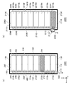
- FIGS. 6A and 6B are diagrams showing an outline of gas discharge in the storage battery module of FIG.
- the present embodiment relates to a storage battery module that stores a plurality of storage battery cells.
- Each of the storage battery cells has a structure in which the positive electrode and the negative electrode face each other, and for example, the positive electrodes are arranged so that the positive electrodes face the same direction.
- gas is generated in the storage battery cell when an internal short circuit or the like occurs.
- the safety mechanism releases the gas from the positive electrode side to the outside of the storage battery cell.
- Such gas has a high temperature and high pressure, and when combustion by the gas occurs, other storage battery cells in the storage battery module also undergo thermal runaway (kindling). Due to this burning, the entire storage battery module or the entire product may burn.
- a space is provided between the structure of the storage battery and the positive electrode side surface of the plurality of storage battery cells, and the space is connected to the exhaust port. The high temperature gas from the storage battery cell is discharged into the space and is discharged to the outside of the storage battery module through the exhaust port.
- one exhaust port is connected to one space. Therefore, when one space is formed in the structure, one exhaust port is provided in the structure.
- FIG. 1 is a perspective view showing the structure of the storage battery module 1000.
- an orthogonal coordinate system including an x axis, ay axis, and az axis is defined.
- the x axis and the y axis are orthogonal to each other in the bottom surface of the storage battery module 1000.
- the z-axis is perpendicular to the x-axis and the y-axis and extends in the height (vertical) direction of the storage battery module 1000.
- the positive directions of the x-axis, the y-axis, and the z-axis are defined in the directions of the arrows in FIG. 1, and the negative directions are defined in the directions opposite to the arrows.
- the positive side of the x-axis is the "front side” or “front side”
- the negative side of the x-axis is the “rear side” or “rear side”
- the positive side of the z-axis is "upper side” or “top side”.
- the negative side of the z-axis may be referred to as the “lower side” or the “bottom side”.
- the positive side in the y-axis direction may be referred to as “right side”
- the negative side in the y-axis may be referred to as “left side”.
- the structure 100 includes a front housing 110, a rear housing 130, and a right lid 352.
- the front housing 110 includes a front surface 112, a front lower surface 114, a front upper surface 116, a first front exhaust opening 118a to a fourth front exhaust opening 118d collectively referred to as a front exhaust opening 118, and a left side surface 150.
- the rear housing 130 includes a rear surface 132, a rear lower surface 134, a rear upper surface 136, and a right side surface 152.
- the respective components of the front housing 110 and the rear housing 130 are connected by screws, welding, an adhesive material, etc., but a publicly known technique may be used, and the description thereof will be omitted here.
- the front surface 112 of the front housing 110 has a rectangular plate shape extending on the yz plane.
- the front lower surface 114 extends rearward from the lower end of the front surface 112, the front upper surface 116 extends rearward from the upper end of the front surface 112, and the left side surface 150 extends rearward from the left end of the front surface 112. Extend.
- Each of the front lower surface 114, the front upper surface 116, and the left side surface 150 has a plate shape.
- the plate shape may be rectangular.
- the rear surface 132 of the rear housing 130 has a rectangular plate shape that spreads on the yz plane.
- the rear lower surface 134 extends from the lower end of the rear surface 132 toward the front side
- the rear upper surface 136 extends from the upper end of the rear surface 132 toward the front side
- the right side surface 152 extends from the right end of the rear surface 132 toward the front side. ..
- Each of the rear lower surface 134, the rear upper surface 136, and the right side surface 152 has a plate shape.
- the plate shape may be rectangular.
- the front lower surface 114 and the front end of the rear lower surface 134 form one lower surface.
- the front upper surface 116 and the rear upper surface 136 form one upper surface.
- the lower surface and the upper surface intersect the front surface 112 and the rear surface 132.
- the front surface 112 may be referred to as a first surface
- the rear surface 132 may be referred to as a second surface
- the lower surface may be referred to as a third surface
- the upper surface may be referred to as a fourth surface.
- the front housing 110 and the rear housing 130 are formed of a material having high thermal conductivity, such as metal or carbon. Therefore, the front surface 112, the front lower surface 114, the front upper surface 116, the rear surface 132, the rear lower surface 134, and the rear upper surface 136 are, for example, metal plates.
- FIG. 2 is an exploded perspective view showing the structure of the storage battery module 1000.
- FIG. 3 is another exploded perspective view showing the structure of the storage battery module 1000, which is a further exploded structure of FIG. 2.
- FIG. 4 is a cross-sectional view showing the structure of the storage battery module 1000, which is a cross-sectional view taken along the line AA′ in FIG. 1.
- FIG. 5 is another cross-sectional view showing the structure of the storage battery module 1000, which is a cross-sectional view taken along the line B-B′ of FIG. 1.
- a combination of the front case 240 and the rear case 250 is housed between the front case 110 and the rear case 130.
- the combination of the front case 240 and the rear case 250 has a hollow box shape and is made of an insulating material such as resin.
- the rear end of the front case 240 and the front end of the rear case 250 are connected, the front case 240 faces the front housing 110, and the rear case 250 faces the rear housing 130. ..
- the first storage battery assembly 200a to the seventh storage battery assembly 200g which are collectively referred to as the storage battery assembly 200, are housed.
- the first storage battery assembly 200a, the second storage battery assembly 200b,..., The sixth storage battery assembly 200f, and the seventh storage battery assembly 200g are arranged in order from the left side to the right side. Therefore, it can be said that the lower surface and the upper surface face each other with the storage battery assembly 200 interposed therebetween.
- a plurality of storage battery cells 210 is arranged in each storage battery assembly 200.
- the storage battery cell 210 is, for example, a cylindrical lithium-ion secondary battery.
- a positive electrode 212 and a negative electrode 214 facing each other are arranged at both ends of the columnar shape of the storage battery cell 210.
- a publicly known technique may be used for the storage battery cell 210, and a safety mechanism for discharging the high-temperature high-pressure gas to the outside when the internal pressure rises due to an internal short circuit or the like is provided. Generally, the high temperature and high pressure gas is discharged from the positive electrode 212 side.
- the plurality of storage battery cells 210 included in each of the first storage battery assembly 200a, the third storage battery assembly 200c, the fifth storage battery assembly 200e, and the seventh storage battery assembly 200g have the positive electrode 212 facing forward, The negative electrode 214 faces the rear side.
- the positive electrode 212 faces the rear side and the negative electrode 214 faces the front side. That is, the direction of the positive electrode 212 is the same in one storage battery assembly 200, but the direction of the positive electrode 212 is opposite between two adjacent storage battery assemblies 200.
- the first storage battery assembly 200a or the like has the first electrode.
- the electrode is the positive electrode 212 and the second electrode is the negative electrode 214.
- the first electrode is the negative electrode 214 and the second electrode is the positive electrode 212.
- the battery holder 230 has a through hole into which each of the plurality of storage battery cells 210 can be inserted, thereby fixing the respective positions of the plurality of storage battery cells 210.
- the battery holder 230 is made of an insulating material such as resin.
- a front case 240 is attached to the front side of the plurality of storage battery cells 210 fixed by the battery holder 230, and a rear case 250 is attached to the rear side of the plurality of storage battery cells 210 fixed by the battery holder 230.
- the front case 240 has a plate-shaped front case plate portion 244 that spreads in the yz plane, and the front case plate portion 244 is provided with a through hole at a position facing the positive electrode 212 of each storage battery cell 210. Further, a first front partition wall 242a is provided on the front surface of the front case plate portion 244 at the position of the boundary between the second storage battery assembly 200b and the third storage battery assembly 200c. Further, a second front partition wall 242b is provided at the position of the boundary between the fourth storage battery assembly 200d and the fifth storage battery assembly 200e, and the position of the boundary between the sixth storage battery assembly 200f and the seventh storage battery assembly 200g. Is provided with a third front partition 242c. The first front partition 242a to the third front partition 242c are collectively referred to as a front partition 242, and the front partition 242 projects toward the front and extends in the vertical direction.
- the front surface of the front case plate 244 is divided into the first front recess 246a to the fourth front recess 246d by the first front partition 242a to the third front partition 242c.
- the second front recess 246b is arranged at a portion sandwiched between the first front partition 242a and the second front partition 242b, that is, at a position facing the third storage battery assembly 200c and the fourth storage battery assembly 200d.
- the first front recess 246a and the third front recess 246c are similar to the second front recess 246b.
- the fourth front recess 246d is arranged at a position facing only the seventh storage battery assembly 200g, and thus is narrower than the first front recess 246a to the third front recess 246c.
- the first front recess 246a to the fourth front recess 246d are collectively referred to as the front recess 246.
- the first front lead plate 300a is fitted in the first front recess 246a
- the second front lead plate 300b is fitted in the second front recess 246b
- the third front lead plate 300c is fitted in the third front recess 246c
- the fourth front lead plate 300d is fitted in the fourth front recess 246d.
- the first front lead plate 300a to the fourth front lead plate 300d are collectively referred to as the front lead plate 300, and the front lead plate 300 has a plate shape.
- the first front lead plate 300a is connected to the positive electrodes 212 of the plurality of storage battery cells 210 of the first storage battery assembly 200a and the negative electrodes 214 of the plurality of storage battery cells 210 of the second storage battery assembly 200b.
- the first front lead plate 300a is provided with a wiring pattern for electrically connecting one positive electrode 212 and one negative electrode 214, one storage battery cell 210 of the first storage battery assembly 200a and a second storage battery cell
- One storage battery cell 210 of the storage battery assembly 200b is connected in series.
- a through hole is provided in a portion of the first front lead plate 300a connected to the positive electrode 212.
- the second front lead plate 300b and the third front lead plate 300c are similar to the first front lead plate 300a.
- the fourth front lead plate 300d is connected only to the positive electrodes 212 of the plurality of storage battery cells 210 of the seventh storage battery assembly 200g. Therefore, the fourth front lead plate 300d is smaller than the first front lead plate 300a to the third front lead plate 300c.
- the rear case 250 has a plate-shaped rear case plate portion 254 that spreads in the yz plane, and the rear case plate portion 254 is provided with a through hole at a position facing the positive electrode 212 of each storage battery cell 210. Be done. Further, as shown in FIG. 5, on the rear surface of the rear case plate portion 254, the first rear partition wall 252a is provided at the boundary position between the first storage battery assembly 200a and the second storage battery assembly 200b. Is provided. In addition, a second rear partition 252b is provided at a boundary position between the third storage battery assembly 200c and the fourth storage battery assembly 200d, and a boundary between the fifth storage battery assembly 200e and the sixth storage battery assembly 200f is provided. A third rear partition 252c is provided at the position. The first rear partition 252a to the third rear partition 252c are collectively referred to as a rear partition 252, and the rear partition 252 projects rearward and extends in the up-down direction.
- the rear surface of the rear case plate 254 is divided into the first rear recess 256a to the fourth rear recess 256d by the first rear partition 252a to the third rear partition 252c.
- the second rear recess 256b is disposed at a portion sandwiched between the first rear partition 252a and the second rear partition 252b, that is, at a position facing the second storage battery assembly 200b and the third storage battery assembly 200c.
- the third rear concave portion 256c and the fourth rear concave portion 256d are similar to the second rear concave portion 256b.
- the first rear recess 256a is arranged at a position facing only the first storage battery assembly 200a, and thus is narrower than the second rear recess 256b to the fourth rear recess 256d.
- the first rear concave portion 256a to the fourth rear concave portion 256d are collectively referred to as the rear concave portion 256.
- the first rear lead plate 302a is fitted in the first rear recess 256a, and the second rear lead plate 302b is fitted in the second rear recess 256b.
- the third rear lead plate 302c is fitted in the third rear recess 256c, and the fourth rear lead plate 302d is fitted in the fourth rear recess 256d.
- the first rear lead plate 302a to the fourth rear lead plate 302d are collectively referred to as the rear lead plate 302, and the rear lead plate 302 has a plate shape.
- the second rear lead plate 302b is connected to the positive electrodes 212 of the plurality of storage battery cells 210 of the second storage battery assembly 200b and the negative electrodes 214 of the plurality of storage battery cells 210 of the third storage battery assembly 200c. Since the second rear side lead plate 302b is provided with a wiring pattern for electrically connecting one positive electrode 212 and one negative electrode 214, one storage battery cell 210 of the second storage battery assembly 200b, One storage battery cell 210 of the three storage battery assembly 200c is connected in series. Here, a through hole is provided in a portion of the second rear lead plate 302b that is connected to the positive electrode 212.
- the third rear lead plate 302c and the fourth rear lead plate 302d are similar to the second rear lead plate 302b.
- the first rear lead plate 302a is connected only to the negative electrodes 214 of the plurality of storage battery cells 210 of the first storage battery assembly 200a. Therefore, the first rear lead plate 302a is smaller than the second rear lead plate 302b to the fourth rear lead plate 302d. With such a front lead plate 300 and a rear lead plate 302, one storage battery cell 210 included in each of the first storage battery assembly 200a to the seventh storage battery assembly 200g is connected in series.
- a control board tray 330 is attached to the upper side of the front case 240 and the rear case 250 that are combined while accommodating the storage battery assembly 200.
- the control board tray 330 is a plate-shaped tray extending in the left-right direction.
- a control board 332 is arranged on the control board tray 330.
- the control board 332 includes an IC (Integrated Circuit) and the like, and controls the operation of the storage battery module 1000.
- the control board 332 has a plate shape extending in the left-right direction similarly to the control board tray 330, but is smaller than the control board tray 330.
- a control board lid 334 is attached so as to cover the upper side of the control board tray 330 on which the control board 332 is arranged.
- the control board lid 334 is a lid for protecting the control board 332, and has a shape that matches the control board tray 330.
- the left side lid 350 is attached to the left side of the front case 240 and the rear case 250, which are combined while accommodating the storage battery assembly 200, and the right side lid 352 is attached to the right side.
- the left lid 350 and the right lid 352 have a plate shape extending in the vertical direction and protect the combination of the front case 240 and the rear case 250 from the side surface.
- the control board tray 330, the control board lid 334, the left side lid 350, and the right side lid 352 are formed of an insulating material such as resin.
- the combination of the front case 240 and the rear case 250 to which the control board tray 330 is attached with the control board lid 334, the left side lid 350, and the right side lid 352 is the same as described above.
- the rear housing 130 As a result, as shown in FIG. 4, a front space 400 (third front space 400c) surrounded by the front surface 112, the front lower surface 114, the front upper surface 116, and the front lead plate 300 (third front lead plate 300c) is formed.
- the 3rd front side lead plate 300c is equivalent to the surface by the side of the some 1st electrode in 5th storage battery assembly 200e and 6th storage battery assembly 200f.
- a portion of the front surface 112 located on the lower surface side of the storage battery cells 210 at the lower surface side ends of the fifth storage battery assembly 200e and the sixth storage battery assembly 200f, or the front lower surface 114 has a third surface.
- a front exhaust port 118c is provided.
- the third front exhaust port 118c is a through hole formed in a portion of the front surface 112 or the front lower surface 114, and can be said to be an opening.
- a rear space 410 (third rear space 410c) surrounded by the rear surface 132, the rear lower surface 134, the rear upper surface 136, and the rear lead plate 302 (third rear lead plate 302c) is formed.
- the third rear lead plate 302c corresponds to a surface of the fourth storage battery assembly 200d and the fifth storage battery assembly 200e on the side of the plurality of second electrodes.
- the portion of the rear surface 132 located on the lower surface side of the storage battery cells 210 at the lower surface side end of the fourth storage battery assembly 200d and the fifth storage battery assembly 200e, or the rear lower surface 134, 2 rear exhaust port 138b (FIG. 2) is provided in the third rear space 410c.
- the second rear exhaust port 138b is a through hole formed in the rear surface 132 or the rear lower surface 134.
- the front space 400 and the rear space 410 will be described in more detail with reference to FIG. 5.
- the first front partition wall 242a to the third front partition wall 242c form the first front space 400a to the fourth front space 400d. Is divided into Therefore, it can be said that the front partition walls 242 partition the adjacent front spaces 400.
- the first front space 400a to the fourth front space 400d are arranged side by side in the left-right direction.
- the first front space 400a to the third front space 400c are arranged facing the two storage battery assemblies 200, but the fourth front space 400d is arranged corresponding to only one storage battery assembly 200. Therefore, the volume of the fourth front space 400d is smaller than the volume of each of the first front space 400a to the third front space 400c.
- one front exhaust port 118 is provided in the lower part of each front space 400. Therefore, one front space 400 has one front exhaust port 118.
- the rear space 410 is divided from the first rear space 410a to the fourth rear space 410d by the first rear partition 252a to the third rear partition 252c. Therefore, it can be said that the rear partition wall 252 partitions the adjacent rear space 410.
- the first rear space 410a to the fourth rear space 410d are arranged side by side in the left-right direction.
- the second rear space 410b to the fourth rear space 410d are arranged facing the two storage battery assemblies 200, but the first rear space 410a is arranged corresponding to only one storage battery assembly 200. Therefore, the volume of the first rear space 410a is smaller than the volume of each of the second rear space 410b to the fourth rear space 410d.
- one rear exhaust port 138 is provided in the lower portion of each of the second rear space 410b to the fourth rear space 410d.
- FIGS. 6A and 6B show an outline of the discharge of the gas 500 in the storage battery module 1000.
- FIG. 6A is a cross-sectional view schematically showing the structure of the storage battery module 1000, and is a cross-sectional view in the same direction as FIG. 4.
- the first storage battery cells 210a to the eighth storage battery cells 210h are arranged from the lower side to the upper side.
- the front space 400 is arranged on the front side of these storage battery cells 210, and the front exhaust port 118 is provided on the front lower surface 114 in contact with the front space 400.
- the third storage battery cell 210c releases the high-temperature and high-pressure gas 500 from the positive electrode 212 side to the front space 400 via the front case 240 and the front lead plate 300.
- the gas 500 released into the front space 400 contacts the front surface 112. Since the front surface 112 is a metal plate, it absorbs heat from the gas 500 with which it comes into contact and radiates heat to the outside of the storage battery module 1000. As described above, the gas 500 is deprived of heat and cooled by the contact with the front surface 112. Further, since the cooled gas 500 is diffused in the front space 400, the pressure of the gas 500 decreases. Further, the gas 500 whose temperature and pressure have dropped is discharged to the outside of the storage battery module 1000 from the front exhaust port 118 provided below the front space 400.
- the volume of the fourth front space 400d is smaller than the volume of each of the first front space 400a to the third front space 400c. Therefore, the pressure in the fourth front space 400d is likely to be higher than the other pressures due to the gas 500 released from the storage battery cell 210. As a result, the third front partition 242c forming the fourth front space 400d is more easily damaged than the other front partition 242.
- the size of the fourth front exhaust port 118d provided in the fourth front space 400d is made larger than that of the other front exhaust ports 118. This suppresses an increase in pressure in the fourth front space 400d. That is, the smaller the size of the front space 400, the larger the area of the front exhaust port 118.
- the front exhaust port 118 is provided on the front upper surface 116, air may flow from the lower portion of the front space 400 that is not completely sealed. Since the inflowing air is discharged from the front exhaust port 118, a flow of air from the lower side to the upper side is generated in the front space 400. Such a flow of air supplies air to the sparks, so that high temperature combustion easily occurs. In the rear space 410 as well, as in the front space 400, the gas 500 is cooled, diffused, and released.
- 6B is a cross-sectional view schematically showing the structure of a storage battery module 2000 that is a comparison target of the storage battery module 1000 of FIG. 6A, and is a cross-sectional view in the same direction as FIG. 6A.
- 6A front surface 112 to front upper surface 116, rear surface 132 to rear upper surface 136, storage battery assembly 200 to negative electrode 214, front case 240, rear case 250, front lead plate 300, rear lead plate 302. ,
- the front exhaust port 2118 is provided in a portion of the front surface 2112 that is in contact with the front space 400 and that faces the positive electrode 2212 of the first storage battery cell 2210a.
- the first storage battery cell 2210a discharges the high temperature and high pressure gas 2500 from the positive electrode 2212 side to the front space 2400 via the front case 2240 and the front lead plate 2300.
- the gas 2500 released to the front space 2400 is released to the outside of the storage battery module 2000 from the front exhaust port 2118. That is, the gas 2500 is not cooled by contact with the front surface 2112. At that time, if a spark is generated, air is supplied to the spark, so that high temperature combustion is likely to occur.
- the gas 500 released from the storage battery cell 210 can be released to the outside from the exhaust port. Further, since the gas 500 in one space is discharged to the outside from one exhaust port, the gas 500 can be sufficiently discharged. Further, since the gas 500 is sufficiently released, it is possible to suppress the occurrence of high temperature combustion. Further, since the gas 500 in one space is discharged to the outside from one exhaust port, the inflow of air into the space can be suppressed. Moreover, since the inflow of air into the space is suppressed, the occurrence of high temperature combustion can be suppressed.
- the positive electrodes 212 have the same direction in different assemblies, a plurality of storage battery cells 210 facing the same direction can be classified into a plurality of assemblies. Further, since the space is divided into the first space and the second space, when the space is large, the small first space and second space can be formed. Further, since one exhaust port is provided for each of the small first space and second space, the gas 500 can be sufficiently discharged. Further, since one exhaust port is provided for each of the small first space and the second space, it is possible to suppress the inflow of air into the first space and the second space. Further, since the front surface 112 is a metal plate, the gas 500 can be cooled.
- the directions of the positive electrodes 212 in the different assemblies are opposite, a plurality of assemblies can be formed according to the directions of the plurality of storage battery cells 210.
- the space is divided into the first space and the second space, the first space and the second space can be formed on the opposite sides of the storage battery assembly 200.
- one exhaust port is provided for each of the first space and the second space, the gas 500 can be sufficiently discharged.
- one exhaust port is provided for each of the first space and the second space, it is possible to suppress the inflow of air into the first space and the second space.
- the front surface 112 and the rear surface 132 are metal plates, the gas 500 can be cooled.
- a storage battery module 1000 is a storage battery assembly in which a plurality of storage battery cells 210 each having a first electrode and a second electrode facing each other are arranged with the first electrodes facing the same direction. 200, a first surface of the storage battery assembly 200 that faces the plurality of first electrodes, a second surface of the storage battery assembly 200 that faces the plurality of second electrodes, and a first surface and a second surface.
- the structure 100 includes a third surface and a fourth surface that are opposed to each other with the storage battery assembly 200 sandwiched therebetween.
- a space surrounded by a plurality of surfaces of the storage battery assembly 200 on the side of the first electrode, the first surface, the third surface, and the fourth surface is formed.
- An exhaust port is provided on a portion of the first surface of the storage battery assembly 200 that is located on the third surface side of the end of the third surface on the third surface side, or on the third surface.
- One space has one exhaust port.
- a first assembly including a plurality of storage battery cells 210 in which the first electrode is the positive electrode 212 and the second electrode is the negative electrode 214, the first electrode is the positive electrode 212, and
- the second assembly includes a plurality of storage battery cells 210 in which the second electrode is the negative electrode 214.
- the space formed in the structure 100 includes a first space surrounded by a plurality of first electrode-side surfaces of the first assembly, a first surface, a third surface, and a fourth surface, and a space in the second assembly. It may include a second space surrounded by a plurality of first electrode-side surfaces, a first surface, a third surface, and a fourth surface.
- the exhaust port is a portion of the first surface located on the third surface side of the end of the first assembly on the third surface side of the first assembly in the first space, or the first exhaust gas disposed on the third surface. Mouth, and a second exhaust port arranged on the third surface of the second space on the third surface side of the end of the second assembly closer to the third surface than the storage battery cell 210. May include and.
- the storage battery module 1000 further includes a partition wall that partitions the first space and the second space.
- the first space may have one first exhaust port.
- the second space has one second exhaust port.
- the first surface is a metal plate.
- the storage battery assembly 200 includes a first assembly including a plurality of storage battery cells 210 in which the first electrode is the positive electrode 212 and the second electrode is the negative electrode 214, and the first electrode is the negative electrode 214, and The second electrode includes a plurality of storage battery cells 210 each having a positive electrode 212.
- the structure body 100 includes a first space surrounded by a plurality of first electrode-side surfaces of the first assembly, a first surface, a third surface, and a fourth surface, and a plurality of second spaces in the second assembly.
- a second space surrounded by the electrode-side surface, the second surface, the third surface, and the fourth surface is formed, and the structure 100 is the third surface-side end of the first aggregate in the first space.
- the first surface located on the third surface side of the storage battery cell 210 or the third exhaust surface is provided with the first exhaust port, and the storage battery cell at the third surface side end of the second assembly in the second space.
- a second exhaust port is provided on a portion of the second surface located closer to the third surface than 210, or on the third surface.
- the first space may have one first exhaust port.
- the second space has one second exhaust port.
- First and second sides are metal plates.
- the exhaust port consists of one opening.
- the exhaust port consists of multiple openings.
- a front space 400 and a rear space 410 are formed.
- only one of the front space 400 and the rear space 410 may be formed.
- a space suitable for arrangement can be formed.
- a plurality of front spaces 400 are arranged.
- the number of the front spaces 400 is not limited to this, and may be one, for example.
- the structure can be simplified when the size of the front space 400 is small. The same applies to the rear space 410.
- the front partition 242 and the rear partition 252 are made of resin or the like.
- the invention is not limited to this, and for example, the front partition wall 242 and the rear partition wall 252 formed of resin or the like may be reinforced by a metal plate or the like from the front space 400 or the rear space 410 side. According to the present modification, even if the pressure of the generated gas 500 increases, the front partition 242 and the rear partition 252 can be less likely to be damaged.
- the exhaust port is composed of one opening.
- the exhaust port may be configured by a plurality of openings.
- the openings are arranged adjacent to each other so that when the gas is discharged from one opening, the gas does not flow from the other opening. According to this modification, the degree of freedom of structure can be improved.
- thermal runaway (similar burning) of an adjacent battery due to high temperature combustion of the thermal runaway battery can be suppressed.
- 100 structure 110 front housing, 112 front surface (first surface), 114 front lower surface (third surface), 116 front upper surface (fourth surface), 118 front exhaust port (exhaust port), 130 rear housing, 132 rear surface (second surface), 134 rear lower surface (third surface), 136 rear upper surface (fourth surface), 138 rear exhaust port (exhaust port), 150 left side surface, 152 right side surface, 200 storage battery assembly (First aggregate, second aggregate)), 210 storage battery cell, 212 positive electrode (first electrode, second electrode), 214 negative electrode (first electrode, second electrode), 230 battery holder, 240 Front case, 242 front partition, 244 front case plate, 246 front recess, 250 rear case, 252 rear partition, 254 rear case plate, 256 rear recess, 300 front lead plate, 302 rear lead plate, 330 control board tray, 332 control board, 334 control board lid, 350 left side lid, 352 right side lid, 400 front space, 410 rear space, 1000 storage battery module.
Abstract
A front-side casing body 110 comprises a front surface 112, a front-side lower surface 114, and a front-side upper surface 116 facing a plurality of positive electrodes 212 in a fifth storage battery aggregate 200e. Third front spaces 400c are formed in the front-side casing body 110, said spaces being surrounded by the surfaces of the plurality of positive electrodes 212 in the fifth storage battery aggregate 200e, the front surface 112, the front-side lower surface 114, and the front-side upper surface 116. The front-side casing body 110 comprises third front-side exhaust ports 118c in either the front surface 112 portion, which is positioned further toward the front-side lower surface 114 side than a storage battery cell 210 at the front-side lower surface 114-side end, in the fifth storage battery aggregate 200e from among the third front spaces 400c, or in the front-side lower surface 114. One of the third front spaces 400c comprises one of the third front-side exhaust ports 118c.
Description
本開示は、蓄電池モジュールに関し、特に複数の蓄電池セルを収納する蓄電池モジュールに関する。
The present disclosure relates to a storage battery module, and particularly to a storage battery module that houses a plurality of storage battery cells.
蓄電池モジュールには、複数の蓄電池セルが収納される。蓄電池セルに短絡が生じると、高温かつ高圧のガスが蓄電池セルから発生する。このガスを蓄電池モジュールの外に排出するために、蓄電池モジュールには、複数の蓄電池セルとは区画された排気経路部が設けられ、排気経路は排気口に接続される(例えば、特許文献1参照)。
The storage battery module contains a plurality of storage battery cells. When a short circuit occurs in a storage battery cell, high temperature and high pressure gas is generated from the storage battery cell. In order to discharge this gas to the outside of the storage battery module, the storage battery module is provided with an exhaust path portion that is partitioned from a plurality of storage battery cells, and the exhaust path is connected to an exhaust port (see, for example, Patent Document 1). ).
排気口の断面積が小さければ空気(酸素)流入量が少なくなり、大きければ増える。空気(酸素)の流入量が多いと電池モジュール内部での燃焼温度が高くなり、熱暴走した電池だけでなく、その隣接電池も熱暴走(類焼)してしまう可能性が高くなる。
The smaller the cross-sectional area of the exhaust port, the smaller the amount of air (oxygen) inflow, and the larger it will increase. When the inflow amount of air (oxygen) is large, the combustion temperature inside the battery module becomes high, and not only the battery that has runaway due to heat but also its adjacent battery may run out of heat (burn out).
本開示はこうした状況に鑑みなされたものであり、その目的は、熱暴走電池の高温燃焼による隣接電池の熱暴走(類焼)を抑制する技術を提供することにある。
The present disclosure has been made in view of such circumstances, and an object thereof is to provide a technique for suppressing thermal runaway (kindling) of an adjacent battery due to high temperature combustion of the thermal runaway battery.
上記課題を解決するために、本開示のある態様の蓄電池モジュールは、互いに反対を向いた第1の電極と第2の電極とを有する蓄電池セルが、第1の電極を同一方向に向けて複数配置される蓄電池集合体と、蓄電池集合体における複数の第1の電極に対向する第1面と、蓄電池集合体における複数の第2の電極に対向する第2面と、第1面と第2面とに交差しながら蓄電池集合体を挟んで互いに対向する第3面と第4面とを含む構造体とを備える。構造体には、蓄電池集合体における複数の第1の電極側の面と第1面と第3面と第4面とに囲まれる空間が形成され、構造体は、空間のうち、蓄電池集合体における第3面側端の蓄電池セルよりも第3面側に位置する第1面の部分、あるいは第3面に排気口を備える。1つの空間は1つの排気口を有する。
In order to solve the above problems, in a storage battery module according to an aspect of the present disclosure, a storage battery cell having a first electrode and a second electrode facing each other is a plurality of storage batteries having the first electrode directed in the same direction. The storage battery assembly to be arranged, a first surface facing the plurality of first electrodes in the storage battery assembly, a second surface facing the plurality of second electrodes in the storage battery assembly, a first surface and a second surface. And a structure including a third surface and a fourth surface that face each other and face each other across the storage battery assembly. A space surrounded by a plurality of first electrode-side surfaces, a first surface, a third surface, and a fourth surface of the storage battery assembly is formed in the structure, and the structure is a storage battery assembly in the space. In the portion of the first surface located on the third surface side with respect to the storage battery cell at the end of the third surface in, the exhaust port is provided on the third surface. One space has one exhaust port.
本開示によれば、熱暴走電池の高温燃焼による隣接電池の熱暴走(類焼)を抑制できる。
According to the present disclosure, thermal runaway (similar burning) of an adjacent battery due to high temperature combustion of the thermal runaway battery can be suppressed.
本開示の実施例を具体的に説明する前に、実施例の概要を説明する。本実施例は、複数の蓄電池セルが収納される蓄電池モジュールに関する。各蓄電池セルは、正極と負極とが互いに反対を向いた構造を有し、例えば、正極が同一方向を向くように並べられる。蓄電池セルがリチウムイオン二次電池である場合、内部短絡等が発生すると蓄電池セル内にガスが発生する。また、ガスの発生により、蓄電池セル内の圧力が増加するが、安全機構によりガスが正極側から蓄電池セル外に放出される。このようなガスは高温高圧であり、ガスによる燃焼が生じると、蓄電池モジュール内の他の蓄電池セルも熱暴走(類焼)する。この類焼により、蓄電池モジュール全体、または製品全体が燃えてしまうおそれがある。ガスによる類焼を抑制するために、蓄電池の構造体と複数の蓄電池セルの正極側の面との間には空間が設けられ、空間は排気口に接続される。蓄電池セルからの高温ガスは空間に放出され、排気口から蓄電池モジュール外に放出される。
Before specifically explaining the example of the present disclosure, an outline of the example will be described. The present embodiment relates to a storage battery module that stores a plurality of storage battery cells. Each of the storage battery cells has a structure in which the positive electrode and the negative electrode face each other, and for example, the positive electrodes are arranged so that the positive electrodes face the same direction. When the storage battery cell is a lithium ion secondary battery, gas is generated in the storage battery cell when an internal short circuit or the like occurs. Moreover, although the pressure inside the storage battery cell increases due to the generation of gas, the safety mechanism releases the gas from the positive electrode side to the outside of the storage battery cell. Such gas has a high temperature and high pressure, and when combustion by the gas occurs, other storage battery cells in the storage battery module also undergo thermal runaway (kindling). Due to this burning, the entire storage battery module or the entire product may burn. In order to suppress burning by gas, a space is provided between the structure of the storage battery and the positive electrode side surface of the plurality of storage battery cells, and the space is connected to the exhaust port. The high temperature gas from the storage battery cell is discharged into the space and is discharged to the outside of the storage battery module through the exhaust port.
このような状況下において、空間が複数に分割された構造を有する場合、ガスは1つの排気口から排出されにくくなる。そのため、ガスによる類焼が生じやすくなる。一方、1つの空間に複数の排気口が接続される場合、ガスは排出されやすくなる。しかしながら、1つの空間に複数の排気口が接続されると、蓄電池モジュール外から空間に空気が流入しやすくなり、ガスによる高温燃焼が生じやすくなる。そのため、ガスによる高温燃焼を抑制するような構造体内の空間と排気口との関係が求められる。本実施例に係る蓄電池モジュールは、1つの空間に1つの排気口を接続する。そのため、構造体内に1つの空間が形成される場合、構造体に1つの排気口が設けられる。また、構造体内に複数の空間が形成される場合、構造体に複数の排気口が設けられる。ここで、一般的に不完全燃焼温度<完全燃焼温度の関係であり、金属を溶かず「ふいご」の様に空気(酸素)を多く送り込むと燃焼温度はさらに高温になる。ろうそくの芯の部分は不完全燃焼で約600℃、炎の先端は約1000℃を超える温度として知られている。以下の説明において、「平行」、「垂直」は、完全な平行、垂直だけではなく、誤差の範囲で平行、垂直からずれている場合も含む。また、「略」は、おおよその範囲で同一であるという意味である。
Under such circumstances, if the space has a structure that is divided into multiple parts, it will be difficult for gas to be discharged from one exhaust port. Therefore, the calcination due to the gas is likely to occur. On the other hand, when a plurality of exhaust ports are connected to one space, the gas is easily discharged. However, when a plurality of exhaust ports are connected to one space, air easily flows into the space from outside the storage battery module, and high-temperature combustion due to gas is likely to occur. Therefore, a relationship between the space inside the structure and the exhaust port is required so as to suppress high temperature combustion due to gas. In the storage battery module according to this embodiment, one exhaust port is connected to one space. Therefore, when one space is formed in the structure, one exhaust port is provided in the structure. In addition, when a plurality of spaces are formed in the structure, a plurality of exhaust ports are provided in the structure. Here, in general, the relationship of incomplete combustion temperature<complete combustion temperature is satisfied, and if a large amount of air (oxygen) is sent in like a "bellows" without melting metal, the combustion temperature becomes higher. It is known that the candle core has an incomplete combustion of about 600°C and the flame tip has a temperature of more than about 1000°C. In the following description, “parallel” and “vertical” include not only perfect parallel and vertical, but also parallel and vertical deviations within the error range. Further, "substantially" means that they are the same in an approximate range.
図1は、蓄電池モジュール1000の構造を示す斜視図である。図1に示すように、x軸、y軸、z軸を含む直交座標系が規定される。x軸、y軸は、蓄電池モジュール1000の底面内において互いに直交する。z軸は、x軸およびy軸に垂直であり、蓄電池モジュール1000の高さ(垂直)方向に延びる。また、x軸、y軸、z軸のそれぞれの正の方向は、図1における矢印の方向に規定され、負の方向は、矢印と逆向きの方向に規定される。また、x軸の正方向側を「前側」あるいは「正面側」、x軸の負方向側を「後側」あるいは「背面側」、z軸の正方向側を「上側」あるいは「天面側」、z軸の負方向側を「下側」あるいは「底面側」ということもある。さらに、y軸方向の正方向側を「右側」、y軸の負方向側を「左側」ということもある。
FIG. 1 is a perspective view showing the structure of the storage battery module 1000. As shown in FIG. 1, an orthogonal coordinate system including an x axis, ay axis, and az axis is defined. The x axis and the y axis are orthogonal to each other in the bottom surface of the storage battery module 1000. The z-axis is perpendicular to the x-axis and the y-axis and extends in the height (vertical) direction of the storage battery module 1000. The positive directions of the x-axis, the y-axis, and the z-axis are defined in the directions of the arrows in FIG. 1, and the negative directions are defined in the directions opposite to the arrows. The positive side of the x-axis is the "front side" or "front side", the negative side of the x-axis is the "rear side" or "rear side", and the positive side of the z-axis is "upper side" or "top side". , And the negative side of the z-axis may be referred to as the “lower side” or the “bottom side”. Further, the positive side in the y-axis direction may be referred to as “right side”, and the negative side in the y-axis may be referred to as “left side”.
構造体100は、前側筐体110、後側筐体130、右側蓋352を含む。前側筐体110は、前面112、前側下面114、前側上面116、前側排気口118と総称される第1前側排気口118aから第4前側排気口118d、左側面150を含む。後側筐体130は、後面132、後側下面134、後側上面136、右側面152を含む。前側筐体110、後側筐体130の各構成要素は、ネジ、溶接、接着材等で接続されているが、公知の技術が使用されればよいので、ここでは説明を省略する。
The structure 100 includes a front housing 110, a rear housing 130, and a right lid 352. The front housing 110 includes a front surface 112, a front lower surface 114, a front upper surface 116, a first front exhaust opening 118a to a fourth front exhaust opening 118d collectively referred to as a front exhaust opening 118, and a left side surface 150. The rear housing 130 includes a rear surface 132, a rear lower surface 134, a rear upper surface 136, and a right side surface 152. The respective components of the front housing 110 and the rear housing 130 are connected by screws, welding, an adhesive material, etc., but a publicly known technique may be used, and the description thereof will be omitted here.
前側筐体110の前面112は、y-z平面上に広がる矩形の板形状を有する。前面112の下側端から後側に向かって前側下面114が延び、前面112の上側端から後側に向かって前側上面116が延び、前面112の左側端から後側に向かって左側面150が延びる。前側下面114と前側上面116と左側面150は、いずれも板形状を有する。板形状は矩形状であってもよい。また、後側筐体130の後面132は、y-z平面上に広がる矩形の板形状を有する。後面132の下側端から前側に向かって後側下面134が延び、後面132の上側端から前側に向かって後側上面136が延び、後面132の右側端から前側に向かって右側面152が延びる。後側下面134と後側上面136と右側面152は、いずれも板形状を有する。板形状は矩形状であってもよい。
The front surface 112 of the front housing 110 has a rectangular plate shape extending on the yz plane. The front lower surface 114 extends rearward from the lower end of the front surface 112, the front upper surface 116 extends rearward from the upper end of the front surface 112, and the left side surface 150 extends rearward from the left end of the front surface 112. Extend. Each of the front lower surface 114, the front upper surface 116, and the left side surface 150 has a plate shape. The plate shape may be rectangular. Further, the rear surface 132 of the rear housing 130 has a rectangular plate shape that spreads on the yz plane. The rear lower surface 134 extends from the lower end of the rear surface 132 toward the front side, the rear upper surface 136 extends from the upper end of the rear surface 132 toward the front side, and the right side surface 152 extends from the right end of the rear surface 132 toward the front side. .. Each of the rear lower surface 134, the rear upper surface 136, and the right side surface 152 has a plate shape. The plate shape may be rectangular.
前側下面114の後側端と、後側下面134の前側端とが接続されることによって、前側下面114と後側下面134は、1つの下面を形成する。また、前側上面116の後側端と、後側上面136の前側端とが接続されることによって、前側上面116と後側上面136は、1つの上面を形成する。下面と上面は、前面112と後面132とに交差する。このように前側筐体110と後側筐体130とが接続されることによって、構造体100は箱形状を有する。その際、構造体100の右側は、右側面152、右側蓋352でふさがれ、構造体100の左側は、左側面150、左側蓋(図示せず)でふさがれる。以下では、前面112を第1面と呼び、後面132を第2面と呼び、下面を第3面と呼び、上面を第4面と呼んでもよい。ここで、前側筐体110と後側筐体130は、熱伝導性の高い材料、例えば、金属、カーボンにより形成される。そのため、前面112、前側下面114、前側上面116、後面132、後側下面134、後側上面136は、例えば、金属板である。
By connecting the rear end of the front lower surface 114 and the front end of the rear lower surface 134, the front lower surface 114 and the rear lower surface 134 form one lower surface. Further, by connecting the rear end of the front upper surface 116 and the front end of the rear upper surface 136, the front upper surface 116 and the rear upper surface 136 form one upper surface. The lower surface and the upper surface intersect the front surface 112 and the rear surface 132. By connecting the front housing 110 and the rear housing 130 in this manner, the structure 100 has a box shape. At this time, the right side of the structure 100 is closed by the right side surface 152 and the right side cover 352, and the left side of the structure 100 is closed by the left side surface 150 and the left side cover (not shown). In the following, the front surface 112 may be referred to as a first surface, the rear surface 132 may be referred to as a second surface, the lower surface may be referred to as a third surface, and the upper surface may be referred to as a fourth surface. Here, the front housing 110 and the rear housing 130 are formed of a material having high thermal conductivity, such as metal or carbon. Therefore, the front surface 112, the front lower surface 114, the front upper surface 116, the rear surface 132, the rear lower surface 134, and the rear upper surface 136 are, for example, metal plates.
以下では、図2から図5を使用しながら、このような蓄電池モジュール1000の構造をさらに説明する。図2は、蓄電池モジュール1000の構造を示す分解斜視図である。図3は、蓄電池モジュール1000の構造を示す別の分解斜視図であり、図2をさらに分解した構造を示す。図4は、蓄電池モジュール1000の構造を示す断面図であり、図1のA-A’線の断面図である。図5は、蓄電池モジュール1000の構造を示す別の断面図であり、図1のB-B’線の断面図である。
The structure of such a storage battery module 1000 will be further described below with reference to FIGS. 2 to 5. FIG. 2 is an exploded perspective view showing the structure of the storage battery module 1000. FIG. 3 is another exploded perspective view showing the structure of the storage battery module 1000, which is a further exploded structure of FIG. 2. FIG. 4 is a cross-sectional view showing the structure of the storage battery module 1000, which is a cross-sectional view taken along the line AA′ in FIG. 1. FIG. 5 is another cross-sectional view showing the structure of the storage battery module 1000, which is a cross-sectional view taken along the line B-B′ of FIG. 1.
前側筐体110と後側筐体130との間には、前側ケース240と後側ケース250との組合せが収納される。前側ケース240と後側ケース250との組合せは中空の箱形状を有しており、絶縁性を有する材料、例えば樹脂により形成される。この組合せでは、前側ケース240の後側端と後側ケース250の前側端が接続されており、前側ケース240は前側筐体110に対向し、後側ケース250は後側筐体130に対向する。前側ケース240と後側ケース250との組合せの内部には、蓄電池集合体200と総称される第1蓄電池集合体200aから第7蓄電池集合体200g、電池ホルダ230が収納される。特に、左側から右側に向かって、第1蓄電池集合体200a、第2蓄電池集合体200b、・・・、第6蓄電池集合体200f、第7蓄電池集合体200gが順に並べられる。そのため、下面と上面は、蓄電池集合体200を挟んで互いに対向するといえる。各蓄電池集合体200には、複数の蓄電池セル210が配置される。
A combination of the front case 240 and the rear case 250 is housed between the front case 110 and the rear case 130. The combination of the front case 240 and the rear case 250 has a hollow box shape and is made of an insulating material such as resin. In this combination, the rear end of the front case 240 and the front end of the rear case 250 are connected, the front case 240 faces the front housing 110, and the rear case 250 faces the rear housing 130. .. Inside the combination of the front case 240 and the rear case 250, the first storage battery assembly 200a to the seventh storage battery assembly 200g, which are collectively referred to as the storage battery assembly 200, are housed. In particular, the first storage battery assembly 200a, the second storage battery assembly 200b,..., The sixth storage battery assembly 200f, and the seventh storage battery assembly 200g are arranged in order from the left side to the right side. Therefore, it can be said that the lower surface and the upper surface face each other with the storage battery assembly 200 interposed therebetween. A plurality of storage battery cells 210 is arranged in each storage battery assembly 200.
蓄電池セル210は、例えば、円柱形のリチウムイオン二次電池である。蓄電池セル210における円柱形の両端には、互いに反対を向いた正極212と負極214とが配置される。蓄電池セル210には公知の技術が使用されればよく、内部短絡等の発生により内部の圧力が上昇した場合、高温高圧ガスを外部に放出する安全機構が備えられる。一般的に、高温高圧ガスは正極212側から放出される。
The storage battery cell 210 is, for example, a cylindrical lithium-ion secondary battery. A positive electrode 212 and a negative electrode 214 facing each other are arranged at both ends of the columnar shape of the storage battery cell 210. A publicly known technique may be used for the storage battery cell 210, and a safety mechanism for discharging the high-temperature high-pressure gas to the outside when the internal pressure rises due to an internal short circuit or the like is provided. Generally, the high temperature and high pressure gas is discharged from the positive electrode 212 side.
ここで、第1蓄電池集合体200a、第3蓄電池集合体200c、第5蓄電池集合体200e、第7蓄電池集合体200gのそれぞれに含まれた複数の蓄電池セル210は、正極212を前側に向け、負極214を後側に向ける。また、第2蓄電池集合体200b、第4蓄電池集合体200d、第6蓄電池集合体200fのそれぞれに含まれた複数の蓄電池セル210は、正極212を後側に向け、負極214を前側に向ける。つまり、1つの蓄電池集合体200内では正極212の方向が同一であるが、隣接した2つの蓄電池集合体200の間では正極212の方向が逆になる。前面112に対向する前側の電極を「第1の電極」と呼び、後面132に対向する後側の電極を「第2の電極」と呼ぶ場合、第1蓄電池集合体200a等では、第1の電極が正極212であり、第2の電極が負極214である。また、第2蓄電池集合体200b等では、第1の電極が負極214であり、第2の電極が正極212である。
Here, the plurality of storage battery cells 210 included in each of the first storage battery assembly 200a, the third storage battery assembly 200c, the fifth storage battery assembly 200e, and the seventh storage battery assembly 200g have the positive electrode 212 facing forward, The negative electrode 214 faces the rear side. In addition, in the plurality of storage battery cells 210 included in each of the second storage battery assembly 200b, the fourth storage battery assembly 200d, and the sixth storage battery assembly 200f, the positive electrode 212 faces the rear side and the negative electrode 214 faces the front side. That is, the direction of the positive electrode 212 is the same in one storage battery assembly 200, but the direction of the positive electrode 212 is opposite between two adjacent storage battery assemblies 200. When the front electrode facing the front surface 112 is referred to as a "first electrode" and the rear electrode facing the rear surface 132 is referred to as a "second electrode", the first storage battery assembly 200a or the like has the first electrode. The electrode is the positive electrode 212 and the second electrode is the negative electrode 214. In addition, in the second storage battery assembly 200b and the like, the first electrode is the negative electrode 214 and the second electrode is the positive electrode 212.
電池ホルダ230は、複数の蓄電池セル210のそれぞれを挿入可能な貫通孔を備えることによって、複数の蓄電池セル210のそれぞれの位置を固定する。電池ホルダ230は、絶縁性を有する材料、例えば樹脂により形成される。電池ホルダ230によって固定された複数の蓄電池セル210の前側には前側ケース240が取り付けられ、電池ホルダ230によって固定された複数の蓄電池セル210の後側には後側ケース250が取り付けられる。
The battery holder 230 has a through hole into which each of the plurality of storage battery cells 210 can be inserted, thereby fixing the respective positions of the plurality of storage battery cells 210. The battery holder 230 is made of an insulating material such as resin. A front case 240 is attached to the front side of the plurality of storage battery cells 210 fixed by the battery holder 230, and a rear case 250 is attached to the rear side of the plurality of storage battery cells 210 fixed by the battery holder 230.
前側ケース240は、y-z平面に広がる板形状の前側ケース板部244を有し、前側ケース板部244には、各蓄電池セル210の正極212に対向した位置に貫通孔が設けられる。また、前側ケース板部244の前側の面において、第2蓄電池集合体200bと第3蓄電池集合体200cとの境界の位置には、第1前側隔壁242aが設けられる。また、第4蓄電池集合体200dと第5蓄電池集合体200eとの境界の位置には、第2前側隔壁242bが設けられ、第6蓄電池集合体200fと第7蓄電池集合体200gとの境界の位置には、第3前側隔壁242cが設けられる。第1前側隔壁242aから第3前側隔壁242cは前側隔壁242と総称され、前側隔壁242は、前側に向かって突出するとともに上下方向に延びる。
The front case 240 has a plate-shaped front case plate portion 244 that spreads in the yz plane, and the front case plate portion 244 is provided with a through hole at a position facing the positive electrode 212 of each storage battery cell 210. Further, a first front partition wall 242a is provided on the front surface of the front case plate portion 244 at the position of the boundary between the second storage battery assembly 200b and the third storage battery assembly 200c. Further, a second front partition wall 242b is provided at the position of the boundary between the fourth storage battery assembly 200d and the fifth storage battery assembly 200e, and the position of the boundary between the sixth storage battery assembly 200f and the seventh storage battery assembly 200g. Is provided with a third front partition 242c. The first front partition 242a to the third front partition 242c are collectively referred to as a front partition 242, and the front partition 242 projects toward the front and extends in the vertical direction.
第1前側隔壁242aから第3前側隔壁242cによって、前側ケース板部244の前側の面は、第1前側凹部246aから第4前側凹部246dに区分される。例えば、第2前側凹部246bは、第1前側隔壁242aと第2前側隔壁242bとに挟まれた部分、つまり第3蓄電池集合体200cと第4蓄電池集合体200dに対向した位置に配置される。第1前側凹部246a、第3前側凹部246cも第2前側凹部246bと同様である。一方、第4前側凹部246dは、第7蓄電池集合体200gだけに対向した位置に配置されるので、第1前側凹部246aから第3前側凹部246cよりも狭い。このような第1前側凹部246aから第4前側凹部246dは前側凹部246と総称される。
The front surface of the front case plate 244 is divided into the first front recess 246a to the fourth front recess 246d by the first front partition 242a to the third front partition 242c. For example, the second front recess 246b is arranged at a portion sandwiched between the first front partition 242a and the second front partition 242b, that is, at a position facing the third storage battery assembly 200c and the fourth storage battery assembly 200d. The first front recess 246a and the third front recess 246c are similar to the second front recess 246b. On the other hand, the fourth front recess 246d is arranged at a position facing only the seventh storage battery assembly 200g, and thus is narrower than the first front recess 246a to the third front recess 246c. The first front recess 246a to the fourth front recess 246d are collectively referred to as the front recess 246.
図2、図3に示されるように、第1前側凹部246aには第1前側リード板300aが嵌め込まれ、第2前側凹部246bには第2前側リード板300bが嵌め込まれる。また、第3前側凹部246cには第3前側リード板300cが嵌め込まれ、第4前側凹部246dには第4前側リード板300dが嵌め込まれる。第1前側リード板300aから第4前側リード板300dは前側リード板300と総称され、前側リード板300は板形状を有する。第1前側リード板300aは、第1蓄電池集合体200aの複数の蓄電池セル210の正極212と、第2蓄電池集合体200bの複数の蓄電池セル210の負極214とに接続される。第1前側リード板300aには、1つの正極212と1つの負極214とを電気的に接続する配線パターンが設けられているので、第1蓄電池集合体200aの1つの蓄電池セル210と、第2蓄電池集合体200bの1つの蓄電池セル210は、直列に接続される。ここで、第1前側リード板300aにおいて正極212と接続される部分には貫通孔が設けられる。第2前側リード板300b、第3前側リード板300cも第1前側リード板300aと同様である。一方、第4前側リード板300dは、第7蓄電池集合体200gの複数の蓄電池セル210の正極212だけに接続される。そのため、第4前側リード板300dは、第1前側リード板300aから第3前側リード板300cよりも小さい。
As shown in FIGS. 2 and 3, the first front lead plate 300a is fitted in the first front recess 246a, and the second front lead plate 300b is fitted in the second front recess 246b. The third front lead plate 300c is fitted in the third front recess 246c, and the fourth front lead plate 300d is fitted in the fourth front recess 246d. The first front lead plate 300a to the fourth front lead plate 300d are collectively referred to as the front lead plate 300, and the front lead plate 300 has a plate shape. The first front lead plate 300a is connected to the positive electrodes 212 of the plurality of storage battery cells 210 of the first storage battery assembly 200a and the negative electrodes 214 of the plurality of storage battery cells 210 of the second storage battery assembly 200b. Since the first front lead plate 300a is provided with a wiring pattern for electrically connecting one positive electrode 212 and one negative electrode 214, one storage battery cell 210 of the first storage battery assembly 200a and a second storage battery cell One storage battery cell 210 of the storage battery assembly 200b is connected in series. Here, a through hole is provided in a portion of the first front lead plate 300a connected to the positive electrode 212. The second front lead plate 300b and the third front lead plate 300c are similar to the first front lead plate 300a. On the other hand, the fourth front lead plate 300d is connected only to the positive electrodes 212 of the plurality of storage battery cells 210 of the seventh storage battery assembly 200g. Therefore, the fourth front lead plate 300d is smaller than the first front lead plate 300a to the third front lead plate 300c.
後側ケース250は、y-z平面に広がる板形状の後側ケース板部254を有し、後側ケース板部254には、各蓄電池セル210の正極212に対向した位置に貫通孔が設けられる。また、図5に示されるように、後側ケース板部254の後側の面において、第1蓄電池集合体200aと第2蓄電池集合体200bとの境界の位置には、第1後側隔壁252aが設けられる。また、第3蓄電池集合体200cと第4蓄電池集合体200dとの境界の位置には、第2後側隔壁252bが設けられ、第5蓄電池集合体200eと第6蓄電池集合体200fとの境界の位置には、第3後側隔壁252cが設けられる。第1後側隔壁252aから第3後側隔壁252cは後側隔壁252と総称され、後側隔壁252は、後側に向かって突出するとともに上下方向に延びる。
The rear case 250 has a plate-shaped rear case plate portion 254 that spreads in the yz plane, and the rear case plate portion 254 is provided with a through hole at a position facing the positive electrode 212 of each storage battery cell 210. Be done. Further, as shown in FIG. 5, on the rear surface of the rear case plate portion 254, the first rear partition wall 252a is provided at the boundary position between the first storage battery assembly 200a and the second storage battery assembly 200b. Is provided. In addition, a second rear partition 252b is provided at a boundary position between the third storage battery assembly 200c and the fourth storage battery assembly 200d, and a boundary between the fifth storage battery assembly 200e and the sixth storage battery assembly 200f is provided. A third rear partition 252c is provided at the position. The first rear partition 252a to the third rear partition 252c are collectively referred to as a rear partition 252, and the rear partition 252 projects rearward and extends in the up-down direction.
第1後側隔壁252aから第3後側隔壁252cによって、後側ケース板部254の後側の面は、第1後側凹部256aから第4後側凹部256dに区分される。例えば、第2後側凹部256bは、第1後側隔壁252aと第2後側隔壁252bとに挟まれた部分、つまり第2蓄電池集合体200bと第3蓄電池集合体200cに対向した位置に配置される。第3後側凹部256c、第4後側凹部256dも第2後側凹部256bと同様である。一方、第1後側凹部256aは、第1蓄電池集合体200aだけに対向した位置に配置されるので、第2後側凹部256bから第4後側凹部256dよりも狭い。このような第1後側凹部256aから第4後側凹部256dは後側凹部256と総称される。
The rear surface of the rear case plate 254 is divided into the first rear recess 256a to the fourth rear recess 256d by the first rear partition 252a to the third rear partition 252c. For example, the second rear recess 256b is disposed at a portion sandwiched between the first rear partition 252a and the second rear partition 252b, that is, at a position facing the second storage battery assembly 200b and the third storage battery assembly 200c. To be done. The third rear concave portion 256c and the fourth rear concave portion 256d are similar to the second rear concave portion 256b. On the other hand, the first rear recess 256a is arranged at a position facing only the first storage battery assembly 200a, and thus is narrower than the second rear recess 256b to the fourth rear recess 256d. The first rear concave portion 256a to the fourth rear concave portion 256d are collectively referred to as the rear concave portion 256.
第1後側凹部256aには第1後側リード板302aが嵌め込まれ、第2後側凹部256bには第2後側リード板302bが嵌め込まれる。また、第3後側凹部256cには第3後側リード板302cが嵌め込まれ、第4後側凹部256dには第4後側リード板302dが嵌め込まれる。第1後側リード板302aから第4後側リード板302dは後側リード板302と総称され、後側リード板302は板形状を有する。第2後側リード板302bは、第2蓄電池集合体200bの複数の蓄電池セル210の正極212と、第3蓄電池集合体200cの複数の蓄電池セル210の負極214とに接続される。第2後側リード板302bには、1つの正極212と1つの負極214とを電気的に接続する配線パターンが設けられているので、第2蓄電池集合体200bの1つの蓄電池セル210と、第3蓄電池集合体200cの1つの蓄電池セル210は、直列に接続される。ここで、第2後側リード板302bにおいて正極212と接続される部分には貫通孔が設けられる。第3後側リード板302c、第4後側リード板302dも第2後側リード板302bと同様である。一方、第1後側リード板302aは、第1蓄電池集合体200aの複数の蓄電池セル210の負極214だけに接続される。そのため、第1後側リード板302aは、第2後側リード板302bから第4後側リード板302dよりも小さい。このような前側リード板300と後側リード板302によって、第1蓄電池集合体200aから第7蓄電池集合体200gのそれぞれに含まれる1つの蓄電池セル210は、直列に接続される。
The first rear lead plate 302a is fitted in the first rear recess 256a, and the second rear lead plate 302b is fitted in the second rear recess 256b. In addition, the third rear lead plate 302c is fitted in the third rear recess 256c, and the fourth rear lead plate 302d is fitted in the fourth rear recess 256d. The first rear lead plate 302a to the fourth rear lead plate 302d are collectively referred to as the rear lead plate 302, and the rear lead plate 302 has a plate shape. The second rear lead plate 302b is connected to the positive electrodes 212 of the plurality of storage battery cells 210 of the second storage battery assembly 200b and the negative electrodes 214 of the plurality of storage battery cells 210 of the third storage battery assembly 200c. Since the second rear side lead plate 302b is provided with a wiring pattern for electrically connecting one positive electrode 212 and one negative electrode 214, one storage battery cell 210 of the second storage battery assembly 200b, One storage battery cell 210 of the three storage battery assembly 200c is connected in series. Here, a through hole is provided in a portion of the second rear lead plate 302b that is connected to the positive electrode 212. The third rear lead plate 302c and the fourth rear lead plate 302d are similar to the second rear lead plate 302b. On the other hand, the first rear lead plate 302a is connected only to the negative electrodes 214 of the plurality of storage battery cells 210 of the first storage battery assembly 200a. Therefore, the first rear lead plate 302a is smaller than the second rear lead plate 302b to the fourth rear lead plate 302d. With such a front lead plate 300 and a rear lead plate 302, one storage battery cell 210 included in each of the first storage battery assembly 200a to the seventh storage battery assembly 200g is connected in series.
図2、3に示されるように、蓄電池集合体200を収納しながら組み合わされた前側ケース240と後側ケース250の上側には、制御基板トレイ330が取り付けられる。制御基板トレイ330は、左右方向に延びる板形状のトレイである。制御基板トレイ330の上には、制御基板332が配置される。制御基板332は、IC(Integrated Circuit)等を搭載しており、蓄電池モジュール1000の動作を制御する。制御基板332は、制御基板トレイ330と同様に左右方向に延びる板形状を有するが、制御基板トレイ330よりも小さい。制御基板332が配置された制御基板トレイ330の上側を覆うように、制御基板蓋334が取り付けられる。制御基板蓋334は、制御基板332を保護するための蓋であり、制御基板トレイ330に合わせた形状を有する。
As shown in FIGS. 2 and 3, a control board tray 330 is attached to the upper side of the front case 240 and the rear case 250 that are combined while accommodating the storage battery assembly 200. The control board tray 330 is a plate-shaped tray extending in the left-right direction. A control board 332 is arranged on the control board tray 330. The control board 332 includes an IC (Integrated Circuit) and the like, and controls the operation of the storage battery module 1000. The control board 332 has a plate shape extending in the left-right direction similarly to the control board tray 330, but is smaller than the control board tray 330. A control board lid 334 is attached so as to cover the upper side of the control board tray 330 on which the control board 332 is arranged. The control board lid 334 is a lid for protecting the control board 332, and has a shape that matches the control board tray 330.
図5に示されるように、蓄電池集合体200を収納しながら組み合わされた前側ケース240と後側ケース250の左側には左側蓋350が取り付けられ、右側には右側蓋352が取り付けられる。左側蓋350と右側蓋352は、上下方向に延びる板形状を有し、前側ケース240と後側ケース250の組合せを側面から保護する。制御基板トレイ330、制御基板蓋334、左側蓋350、右側蓋352は、絶縁性を有する材料、例えば樹脂により形成される。
As shown in FIG. 5, the left side lid 350 is attached to the left side of the front case 240 and the rear case 250, which are combined while accommodating the storage battery assembly 200, and the right side lid 352 is attached to the right side. The left lid 350 and the right lid 352 have a plate shape extending in the vertical direction and protect the combination of the front case 240 and the rear case 250 from the side surface. The control board tray 330, the control board lid 334, the left side lid 350, and the right side lid 352 are formed of an insulating material such as resin.
図2に示されるように、制御基板トレイ330から制御基板蓋334、左側蓋350、右側蓋352が取り付けられた前側ケース240と後側ケース250との組合せは、前述のごとく、前側筐体110と後側筐体130との間に配置される。これにより、図4に示されるように、前面112と前側下面114と前側上面116と前側リード板300(第3前側リード板300c)に囲まれる前空間400(第3前空間400c)が形成される。ここで、第3前側リード板300cは、第5蓄電池集合体200eと第6蓄電池集合体200fにおける複数の第1の電極側の面に相当する。第3前空間400cのうち、第5蓄電池集合体200eと第6蓄電池集合体200fにおける下面側端の蓄電池セル210よりも下面側に位置する前面112の部分、あるいは前側下面114には、第3前側排気口118cが設けられる。第3前側排気口118cは、前面112の部分あるいは前側下面114に形成された貫通孔であり、これは開口であるともいえる。
As shown in FIG. 2, the combination of the front case 240 and the rear case 250 to which the control board tray 330 is attached with the control board lid 334, the left side lid 350, and the right side lid 352 is the same as described above. And the rear housing 130. As a result, as shown in FIG. 4, a front space 400 (third front space 400c) surrounded by the front surface 112, the front lower surface 114, the front upper surface 116, and the front lead plate 300 (third front lead plate 300c) is formed. It Here, the 3rd front side lead plate 300c is equivalent to the surface by the side of the some 1st electrode in 5th storage battery assembly 200e and 6th storage battery assembly 200f. In the third front space 400c, a portion of the front surface 112 located on the lower surface side of the storage battery cells 210 at the lower surface side ends of the fifth storage battery assembly 200e and the sixth storage battery assembly 200f, or the front lower surface 114 has a third surface. A front exhaust port 118c is provided. The third front exhaust port 118c is a through hole formed in a portion of the front surface 112 or the front lower surface 114, and can be said to be an opening.
また、後面132と後側下面134と後側上面136と後側リード板302(第3後側リード板302c)に囲まれる後空間410(第3後空間410c)が形成される。ここで、第3後側リード板302cは、第4蓄電池集合体200dと第5蓄電池集合体200eにおける複数の第2の電極側の面に相当する。第3後空間410cのうち、第4蓄電池集合体200dと第5蓄電池集合体200eにおける下面側端の蓄電池セル210よりも下面側に位置する後面132の部分、あるいは後側下面134には、第2後側排気口138b(図2)が設けられる。第2後側排気口138bは、後面132の部分あるいは後側下面134に形成された貫通孔である。
Also, a rear space 410 (third rear space 410c) surrounded by the rear surface 132, the rear lower surface 134, the rear upper surface 136, and the rear lead plate 302 (third rear lead plate 302c) is formed. Here, the third rear lead plate 302c corresponds to a surface of the fourth storage battery assembly 200d and the fifth storage battery assembly 200e on the side of the plurality of second electrodes. In the third rear space 410c, the portion of the rear surface 132 located on the lower surface side of the storage battery cells 210 at the lower surface side end of the fourth storage battery assembly 200d and the fifth storage battery assembly 200e, or the rear lower surface 134, 2 rear exhaust port 138b (FIG. 2) is provided. The second rear exhaust port 138b is a through hole formed in the rear surface 132 or the rear lower surface 134.
前空間400と後空間410について、図5を使用してさらに詳細に説明すると、前空間400は、第1前側隔壁242aから第3前側隔壁242cによって、第1前空間400aから第4前空間400dに分割される。そのため、前側隔壁242は、隣接した前空間400を仕切るともいえる。第1前空間400aから第4前空間400dは左右方向に並んで配置される。特に、第1前空間400aから第3前空間400cは2つの蓄電池集合体200に対向して配置されるが、第4前空間400dは1つの蓄電池集合体200だけに対応して配置される。そのため、第4前空間400dの容積は、第1前空間400aから第3前空間400cのそれぞれの容積よりも小さい。また、各前空間400の下側の部分には1つの前側排気口118が設けられる。そのため、1つの前空間400は1つの前側排気口118を有する。
The front space 400 and the rear space 410 will be described in more detail with reference to FIG. 5. In the front space 400, the first front partition wall 242a to the third front partition wall 242c form the first front space 400a to the fourth front space 400d. Is divided into Therefore, it can be said that the front partition walls 242 partition the adjacent front spaces 400. The first front space 400a to the fourth front space 400d are arranged side by side in the left-right direction. In particular, the first front space 400a to the third front space 400c are arranged facing the two storage battery assemblies 200, but the fourth front space 400d is arranged corresponding to only one storage battery assembly 200. Therefore, the volume of the fourth front space 400d is smaller than the volume of each of the first front space 400a to the third front space 400c. Further, one front exhaust port 118 is provided in the lower part of each front space 400. Therefore, one front space 400 has one front exhaust port 118.
また、後空間410は、第1後側隔壁252aから第3後側隔壁252cによって、第1後空間410aから第4後空間410dに分割される。そのため、後側隔壁252は、隣接した後空間410を仕切るともいえる。第1後空間410aから第4後空間410dは左右方向に並んで配置される。特に、第2後空間410bから第4後空間410dは2つの蓄電池集合体200に対向して配置されるが、第1後空間410aは1つの蓄電池集合体200だけに対応して配置される。そのため、第1後空間410aの容積は、第2後空間410bから第4後空間410dのそれぞれの容積よりも小さい。また、第2後空間410bから第4後空間410dのそれぞれの下側の部分には1つの後側排気口138が設けられる。
Further, the rear space 410 is divided from the first rear space 410a to the fourth rear space 410d by the first rear partition 252a to the third rear partition 252c. Therefore, it can be said that the rear partition wall 252 partitions the adjacent rear space 410. The first rear space 410a to the fourth rear space 410d are arranged side by side in the left-right direction. In particular, the second rear space 410b to the fourth rear space 410d are arranged facing the two storage battery assemblies 200, but the first rear space 410a is arranged corresponding to only one storage battery assembly 200. Therefore, the volume of the first rear space 410a is smaller than the volume of each of the second rear space 410b to the fourth rear space 410d. Further, one rear exhaust port 138 is provided in the lower portion of each of the second rear space 410b to the fourth rear space 410d.
図6(a)-(b)は、蓄電池モジュール1000におけるガス500の排出の概要を示す。図6(a)は、蓄電池モジュール1000の構造を簡略に示す断面図であり、かつ図4と同一方向の断面図である。ここでは、一例として、第1蓄電池セル210aから第8蓄電池セル210hが下側から上側に向かって並べられる。前述のごとく、これらの蓄電池セル210の前側に前空間400が配置され、前空間400に接する前側下面114に前側排気口118が設けられる。
FIGS. 6A and 6B show an outline of the discharge of the gas 500 in the storage battery module 1000. FIG. 6A is a cross-sectional view schematically showing the structure of the storage battery module 1000, and is a cross-sectional view in the same direction as FIG. 4. Here, as an example, the first storage battery cells 210a to the eighth storage battery cells 210h are arranged from the lower side to the upper side. As described above, the front space 400 is arranged on the front side of these storage battery cells 210, and the front exhaust port 118 is provided on the front lower surface 114 in contact with the front space 400.
第3蓄電池セル210cにおいて内部短絡等により熱暴走が発生すると、第3蓄電池セル210cは高温高圧のガス500を正極212側から前側ケース240、前側リード板300経由で前空間400に放出する。前空間400に放出されたガス500は、前面112に接触する。前面112は、金属板であるので、接触したガス500から熱を吸収し、蓄電池モジュール1000の外部に熱を放出する。このようにガス500は、前面112との接触によって熱を奪われ冷やされる。また、冷やされたガス500は前空間400内で拡散されるので、ガス500の圧力は低下する。さらに、温度と圧力が低下したガス500は、前空間400の下側に設けられた前側排気口118から蓄電池モジュール1000の外部に放出される。
When thermal runaway occurs in the third storage battery cell 210c due to an internal short circuit or the like, the third storage battery cell 210c releases the high-temperature and high-pressure gas 500 from the positive electrode 212 side to the front space 400 via the front case 240 and the front lead plate 300. The gas 500 released into the front space 400 contacts the front surface 112. Since the front surface 112 is a metal plate, it absorbs heat from the gas 500 with which it comes into contact and radiates heat to the outside of the storage battery module 1000. As described above, the gas 500 is deprived of heat and cooled by the contact with the front surface 112. Further, since the cooled gas 500 is diffused in the front space 400, the pressure of the gas 500 decreases. Further, the gas 500 whose temperature and pressure have dropped is discharged to the outside of the storage battery module 1000 from the front exhaust port 118 provided below the front space 400.
このようなガス500の流れによって、第3蓄電池セル210cからガス500が放出される際に火花が生じても、冷却・拡散・放出がなされるので、高温燃焼は生じにくくなる。ここで、第4前空間400dの容積は、第1前空間400aから第3前空間400cのそれぞれの容積よりも小さい。そのため、蓄電池セル210から放出されたガス500によって、第4前空間400dでの圧力は、それ以外の圧力よりも高くなりやすい。これにより、第4前空間400dを形成している第3前側隔壁242cは、他の前側隔壁242よりも破損されやすくなる。本実施例では、第3前側隔壁242cの破損を防止するために、第4前空間400dに設けられる第4前側排気口118dの大きさが、他の前側排気口118よりも大きくされる。これにより、第4前空間400dにおける圧力の増加が抑制される。つまり、前空間400の大きさが小さくなるほど、前側排気口118の面積が大きくされる。
Even if a spark is generated when the gas 500 is discharged from the third storage battery cell 210c by such a flow of the gas 500, cooling, diffusion, and discharge are performed, so that high temperature combustion is less likely to occur. Here, the volume of the fourth front space 400d is smaller than the volume of each of the first front space 400a to the third front space 400c. Therefore, the pressure in the fourth front space 400d is likely to be higher than the other pressures due to the gas 500 released from the storage battery cell 210. As a result, the third front partition 242c forming the fourth front space 400d is more easily damaged than the other front partition 242. In the present embodiment, in order to prevent damage to the third front partition 242c, the size of the fourth front exhaust port 118d provided in the fourth front space 400d is made larger than that of the other front exhaust ports 118. This suppresses an increase in pressure in the fourth front space 400d. That is, the smaller the size of the front space 400, the larger the area of the front exhaust port 118.
仮に、前側排気口118が、前側上面116に設けられている場合、完全密封でない前空間400の下部から空気が流入する可能性がある。流入した空気は前側排気口118から排出されるので、前空間400内に下側から上側に向かう空気の流れが生じる。このような空気の流れにより、火花に空気が供給されるので、高温燃焼が生じやすくなる。後空間410においても、前空間400と同様に、ガス500の冷却・拡散・放出がなされる。
If the front exhaust port 118 is provided on the front upper surface 116, air may flow from the lower portion of the front space 400 that is not completely sealed. Since the inflowing air is discharged from the front exhaust port 118, a flow of air from the lower side to the upper side is generated in the front space 400. Such a flow of air supplies air to the sparks, so that high temperature combustion easily occurs. In the rear space 410 as well, as in the front space 400, the gas 500 is cooled, diffused, and released.
図6(b)は、図6(a)の蓄電池モジュール1000の比較対象となる蓄電池モジュール2000の構造を簡略に示す断面図であり、かつ図6(a)と同一方向の断面図である。前面2112から前側上面2116、後面2132から後側上面2136、蓄電池集合体2200から負極2214、前側ケース2240、後側ケース2250、前側リード板2300、後側リード板2302、前空間2400、後空間2410は、図6(a)の前面112から前側上面116、後面132から後側上面136、蓄電池集合体200から負極214、前側ケース240、後側ケース250、前側リード板300、後側リード板302、前空間400、後空間410と同一である。ここでは、前空間400に接する前面2112のうち、第1蓄電池セル2210aの正極2212に対向する部分に、前側排気口2118が設けられる。
6B is a cross-sectional view schematically showing the structure of a storage battery module 2000 that is a comparison target of the storage battery module 1000 of FIG. 6A, and is a cross-sectional view in the same direction as FIG. 6A. Front surface 2112 to front upper surface 2116, rear surface 2132 to rear upper surface 2136, storage battery assembly 2200 to negative electrode 2214, front case 2240, rear case 2250, front lead plate 2300, rear lead plate 2302, front space 2400, rear space 2410. 6A, front surface 112 to front upper surface 116, rear surface 132 to rear upper surface 136, storage battery assembly 200 to negative electrode 214, front case 240, rear case 250, front lead plate 300, rear lead plate 302. , The front space 400 and the rear space 410. Here, the front exhaust port 2118 is provided in a portion of the front surface 2112 that is in contact with the front space 400 and that faces the positive electrode 2212 of the first storage battery cell 2210a.
第1蓄電池セル2210aにおいて内部短絡等により熱暴走が発生すると、第1蓄電池セル2210aは高温高圧のガス2500を正極2212側から前側ケース2240、前側リード板2300経由で前空間2400に放出する。前空間2400に放出されたガス2500は、前側排気口2118から蓄電池モジュール2000の外部に放出される。つまり、ガス2500には、前面2112との接触による冷却がなされない。その際、火花が生じていれば、火花に空気が供給されるので、高温燃焼が生じやすくなる。
When thermal runaway occurs in the first storage battery cell 2210a due to an internal short circuit or the like, the first storage battery cell 2210a discharges the high temperature and high pressure gas 2500 from the positive electrode 2212 side to the front space 2400 via the front case 2240 and the front lead plate 2300. The gas 2500 released to the front space 2400 is released to the outside of the storage battery module 2000 from the front exhaust port 2118. That is, the gas 2500 is not cooled by contact with the front surface 2112. At that time, if a spark is generated, air is supplied to the spark, so that high temperature combustion is likely to occur.
本実施例によれば、構造体100の内部に形成された1つの空間は1つの排気口を有するので、蓄電池セル210から放出したガス500を排気口から外部に放出できる。また、1つの空間内のガス500が1つの排気口から外部に放出されるので、ガス500を十分に放出できる。また、ガス500が十分に放出されるので、高温燃焼の発生を抑制できる。また、1つの空間内のガス500が1つの排気口から外部に放出されるので、空間内への空気の流入を抑制できる。また、空間内への空気の流入が抑制されるので、高温燃焼の発生を抑制できる。
According to the present embodiment, since one space formed inside the structure 100 has one exhaust port, the gas 500 released from the storage battery cell 210 can be released to the outside from the exhaust port. Further, since the gas 500 in one space is discharged to the outside from one exhaust port, the gas 500 can be sufficiently discharged. Further, since the gas 500 is sufficiently released, it is possible to suppress the occurrence of high temperature combustion. Further, since the gas 500 in one space is discharged to the outside from one exhaust port, the inflow of air into the space can be suppressed. Moreover, since the inflow of air into the space is suppressed, the occurrence of high temperature combustion can be suppressed.
また、異なった集合体において正極212の向きが共通であるので、同一方向を向いた複数の蓄電池セル210を複数の集合体に分類できる。また、空間を第1空間と第2空間とに分割するので、空間が大きい場合に小さな第1空間と第2空間を形成できる。また、小さな第1空間と第2空間のそれぞれに対して1つの排気口を設けるので、ガス500を十分に放出できる。また、小さな第1空間と第2空間のそれぞれに対して1つの排気口を設けるので、第1空間内と第2空間内への空気の流入を抑制できる。また、前面112は金属板であるので、ガス500を冷却できる。
Also, since the positive electrodes 212 have the same direction in different assemblies, a plurality of storage battery cells 210 facing the same direction can be classified into a plurality of assemblies. Further, since the space is divided into the first space and the second space, when the space is large, the small first space and second space can be formed. Further, since one exhaust port is provided for each of the small first space and second space, the gas 500 can be sufficiently discharged. Further, since one exhaust port is provided for each of the small first space and the second space, it is possible to suppress the inflow of air into the first space and the second space. Further, since the front surface 112 is a metal plate, the gas 500 can be cooled.
また、異なった集合体において正極212の向きが逆であるので、複数の蓄電池セル210の方向に応じて複数の集合体を形成できる。また、空間を第1空間と第2空間とに分割するので、蓄電池集合体200を挟んで反対側に第1空間と第2空間を形成できる。また、第1空間と第2空間のそれぞれに対して1つの排気口を設けるので、ガス500を十分に放出できる。また、第1空間と第2空間のそれぞれに対して1つの排気口を設けるので、第1空間内と第2空間内への空気の流入を抑制できる。また、前面112と後面132は金属板であるので、ガス500を冷却できる。
Moreover, since the directions of the positive electrodes 212 in the different assemblies are opposite, a plurality of assemblies can be formed according to the directions of the plurality of storage battery cells 210. Moreover, since the space is divided into the first space and the second space, the first space and the second space can be formed on the opposite sides of the storage battery assembly 200. Moreover, since one exhaust port is provided for each of the first space and the second space, the gas 500 can be sufficiently discharged. Further, since one exhaust port is provided for each of the first space and the second space, it is possible to suppress the inflow of air into the first space and the second space. Further, since the front surface 112 and the rear surface 132 are metal plates, the gas 500 can be cooled.
本開示の一態様の概要は、次の通りである。本開示のある態様の蓄電池モジュール1000は、互いに反対を向いた第1の電極と第2の電極とを有する蓄電池セル210が、第1の電極を同一方向に向けて複数配置される蓄電池集合体200と、蓄電池集合体200における複数の第1の電極に対向する第1面と、蓄電池集合体200における複数の第2の電極に対向する第2面と、第1面と第2面とに交差しながら蓄電池集合体200を挟んで互いに対向する第3面と第4面とを含む構造体100とを備える。構造体100には、蓄電池集合体200における複数の第1の電極側の面と第1面と第3面と第4面とに囲まれる空間が形成され、構造体100は、空間のうち、蓄電池集合体200における第3面側端の蓄電池セル210よりも第3面側に位置する第1面の部分、あるいは第3面に排気口を備える。1つの空間は1つの排気口を有する。
The outline of one aspect of the present disclosure is as follows. A storage battery module 1000 according to an aspect of the present disclosure is a storage battery assembly in which a plurality of storage battery cells 210 each having a first electrode and a second electrode facing each other are arranged with the first electrodes facing the same direction. 200, a first surface of the storage battery assembly 200 that faces the plurality of first electrodes, a second surface of the storage battery assembly 200 that faces the plurality of second electrodes, and a first surface and a second surface. The structure 100 includes a third surface and a fourth surface that are opposed to each other with the storage battery assembly 200 sandwiched therebetween. In the structure 100, a space surrounded by a plurality of surfaces of the storage battery assembly 200 on the side of the first electrode, the first surface, the third surface, and the fourth surface is formed. An exhaust port is provided on a portion of the first surface of the storage battery assembly 200 that is located on the third surface side of the end of the third surface on the third surface side, or on the third surface. One space has one exhaust port.
蓄電池集合体200は、第1の電極が正極212であり、かつ第2の電極が負極214である複数の蓄電池セル210を含む第1集合体と、第1の電極が正極212であり、かつ第2の電極が負極214である複数の蓄電池セル210を含む第2集合体とを含む。
In the storage battery assembly 200, a first assembly including a plurality of storage battery cells 210 in which the first electrode is the positive electrode 212 and the second electrode is the negative electrode 214, the first electrode is the positive electrode 212, and The second assembly includes a plurality of storage battery cells 210 in which the second electrode is the negative electrode 214.
構造体100に形成される空間は、第1集合体における複数の第1の電極側の面と第1面と第3面と第4面とに囲まれる第1空間と、第2集合体における複数の第1の電極側の面と第1面と第3面と第4面とに囲まれる第2空間とを含んでもよい。排気口は、第1空間のうち、第1集合体における第3面側端の蓄電池セル210よりも第3面側に位置する第1面の部分、あるいは第3面に配置される第1排気口と、第2空間のうち、第2集合体における第3面側端の蓄電池セル210よりも第3面側に位置する第1面の部分、あるいは第3面に配置される第2排気口とを含んでもよい。本蓄電池モジュール1000は、第1空間と第2空間とを仕切る隔壁をさらに備える。
The space formed in the structure 100 includes a first space surrounded by a plurality of first electrode-side surfaces of the first assembly, a first surface, a third surface, and a fourth surface, and a space in the second assembly. It may include a second space surrounded by a plurality of first electrode-side surfaces, a first surface, a third surface, and a fourth surface. The exhaust port is a portion of the first surface located on the third surface side of the end of the first assembly on the third surface side of the first assembly in the first space, or the first exhaust gas disposed on the third surface. Mouth, and a second exhaust port arranged on the third surface of the second space on the third surface side of the end of the second assembly closer to the third surface than the storage battery cell 210. May include and. The storage battery module 1000 further includes a partition wall that partitions the first space and the second space.
第1空間は、1つの第1排気口を有してもよい。第2空間は、1つの第2排気口を有する。
The first space may have one first exhaust port. The second space has one second exhaust port.
第1面は金属板である。
The first surface is a metal plate.
蓄電池集合体200は、第1の電極が正極212であり、かつ第2の電極が負極214である複数の蓄電池セル210を含む第1集合体と、第1の電極が負極214であり、かつ第2の電極が正極212である複数の蓄電池セル210を含む第2集合体とを含む。
The storage battery assembly 200 includes a first assembly including a plurality of storage battery cells 210 in which the first electrode is the positive electrode 212 and the second electrode is the negative electrode 214, and the first electrode is the negative electrode 214, and The second electrode includes a plurality of storage battery cells 210 each having a positive electrode 212.
構造体100には、第1集合体における複数の第1の電極側の面と第1面と第3面と第4面とに囲まれる第1空間と、第2集合体における複数の第2の電極側の面と第2面と第3面と第4面とに囲まれる第2空間とが形成され、構造体100は、第1空間のうち、第1集合体における第3面側端の蓄電池セル210よりも第3面側に位置する第1面の部分、あるいは第3面に第1排気口を備え、第2空間のうち、第2集合体における第3面側端の蓄電池セル210よりも第3面側に位置する第2面の部分、あるいは第3面に第2排気口を備える。
The structure body 100 includes a first space surrounded by a plurality of first electrode-side surfaces of the first assembly, a first surface, a third surface, and a fourth surface, and a plurality of second spaces in the second assembly. A second space surrounded by the electrode-side surface, the second surface, the third surface, and the fourth surface is formed, and the structure 100 is the third surface-side end of the first aggregate in the first space. Of the first surface located on the third surface side of the storage battery cell 210 or the third exhaust surface is provided with the first exhaust port, and the storage battery cell at the third surface side end of the second assembly in the second space. A second exhaust port is provided on a portion of the second surface located closer to the third surface than 210, or on the third surface.
第1空間は、1つの第1排気口を有してもよい。第2空間は、1つの第2排気口を有する。
The first space may have one first exhaust port. The second space has one second exhaust port.
第1面と第2面は金属板である。
First and second sides are metal plates.
排気口は1つの開口から構成される。
The exhaust port consists of one opening.
排気口は複数の開口から構成される。
The exhaust port consists of multiple openings.
以上、本開示を実施例をもとに説明した。この実施例は例示であり、それらの各構成要素あるいは各処理プロセスの組合せにいろいろな変形例が可能なこと、またそうした変形例も本開示の範囲にあることは当業者に理解されるところである。
Above, the present disclosure has been described based on the embodiments. It should be understood by those skilled in the art that this embodiment is an exemplification, and that various modifications can be made to the combinations of the respective constituent elements or the respective processing processes, and that such modifications are also within the scope of the present disclosure. ..
本実施例において、前空間400と後空間410とが形成される。しかしながらこれに限らず例えば、前空間400と後空間410の一方だけが形成されてもよい。本変形例によれば、すべての蓄電池セル210が同一方向を向いて配置されている場合に、配置に適した空間を形成できる。
In this embodiment, a front space 400 and a rear space 410 are formed. However, not limited to this, for example, only one of the front space 400 and the rear space 410 may be formed. According to this modification, when all the storage battery cells 210 are arranged in the same direction, a space suitable for arrangement can be formed.
本実施例において、複数の前空間400が並べられる。しかしながらこれに限らず例えば、前空間400の数は1つでもよい。本変形例によれば、前空間400のサイズが小さい場合に構造を簡易にできる。また、後空間410についても同様である。
In this embodiment, a plurality of front spaces 400 are arranged. However, the number of the front spaces 400 is not limited to this, and may be one, for example. According to this modification, the structure can be simplified when the size of the front space 400 is small. The same applies to the rear space 410.
本実施例において、前側隔壁242、後側隔壁252は、樹脂等により形成されている。しかしながらこれに限らず例えば、樹脂等により形成された前側隔壁242、後側隔壁252は、前空間400あるいは後空間410側から金属板等によって補強されてもよい。本変形例によれば、発生したガス500の圧力が高くなっても、前側隔壁242、後側隔壁252を破損しにくくできる。
In this embodiment, the front partition 242 and the rear partition 252 are made of resin or the like. However, the invention is not limited to this, and for example, the front partition wall 242 and the rear partition wall 252 formed of resin or the like may be reinforced by a metal plate or the like from the front space 400 or the rear space 410 side. According to the present modification, even if the pressure of the generated gas 500 increases, the front partition 242 and the rear partition 252 can be less likely to be damaged.
本実施例において、排気口は1つの開口から構成されている。しかしながらこれに限らず例えば、排気口は複数の開口から構成されてもよい。そのような場合、各開口は、1つの開口から気体が排出されたときに、他の開口から気体が流入しない程度に隣接して配置される。本変形例によれば、構造の自由度を向上できる。
In this embodiment, the exhaust port is composed of one opening. However, not limited to this, for example, the exhaust port may be configured by a plurality of openings. In such a case, the openings are arranged adjacent to each other so that when the gas is discharged from one opening, the gas does not flow from the other opening. According to this modification, the degree of freedom of structure can be improved.
本開示によれば、熱暴走電池の高温燃焼による隣接電池の熱暴走(類焼)を抑制できる。
According to the present disclosure, thermal runaway (similar burning) of an adjacent battery due to high temperature combustion of the thermal runaway battery can be suppressed.
100 構造体、 110 前側筐体、 112 前面(第1面)、 114 前側下面(第3面)、 116 前側上面(第4面)、 118 前側排気口(排気口)、 130 後側筐体、 132 後面(第2面)、 134 後側下面(第3面)、 136 後側上面(第4面)、 138 後側排気口(排気口)、 150 左側面、 152 右側面、 200 蓄電池集合体(第1集合体、第2集合体))、 210 蓄電池セル、 212 正極(第1の電極、第2の電極)、 214 負極(第1の電極、第2の電極)、 230 電池ホルダ、 240 前側ケース、 242 前側隔壁、 244 前側ケース板部、 246 前側凹部、 250 後側ケース、 252 後側隔壁、 254 後側ケース板部、 256 後側凹部、 300 前側リード板、 302 後側リード板、 330 制御基板トレイ、 332 制御基板、 334 制御基板蓋、 350 左側蓋、 352 右側蓋、 400 前空間、 410 後空間、 1000 蓄電池モジュール。
100 structure, 110 front housing, 112 front surface (first surface), 114 front lower surface (third surface), 116 front upper surface (fourth surface), 118 front exhaust port (exhaust port), 130 rear housing, 132 rear surface (second surface), 134 rear lower surface (third surface), 136 rear upper surface (fourth surface), 138 rear exhaust port (exhaust port), 150 left side surface, 152 right side surface, 200 storage battery assembly (First aggregate, second aggregate)), 210 storage battery cell, 212 positive electrode (first electrode, second electrode), 214 negative electrode (first electrode, second electrode), 230 battery holder, 240 Front case, 242 front partition, 244 front case plate, 246 front recess, 250 rear case, 252 rear partition, 254 rear case plate, 256 rear recess, 300 front lead plate, 302 rear lead plate, 330 control board tray, 332 control board, 334 control board lid, 350 left side lid, 352 right side lid, 400 front space, 410 rear space, 1000 storage battery module.
Claims (11)
- 互いに反対を向いた第1の電極と第2の電極とを有する蓄電池セルが、前記第1の電極を同一方向に向けて複数配置される蓄電池集合体と、
前記蓄電池集合体における複数の前記第1の電極に対向する第1面と、前記蓄電池集合体における複数の前記第2の電極に対向する第2面と、前記第1面と前記第2面とに交差しながら前記蓄電池集合体を挟んで互いに対向する第3面と第4面とを含む構造体とを備え、
前記構造体には、前記蓄電池集合体における複数の前記第1の電極側の面と前記第1面と前記第3面と前記第4面とに囲まれる空間が形成され、
前記構造体は、前記空間のうち、前記蓄電池集合体における前記第3面側端の前記蓄電池セルよりも前記第3面側に位置する前記第1面の部分、あるいは前記第3面に排気口を備え、
1つの前記空間は1つの前記排気口を有する、
蓄電池モジュール。 A storage battery assembly in which a plurality of storage battery cells having first electrodes and second electrodes facing each other are arranged with the first electrodes facing the same direction,
A first surface of the storage battery assembly facing the plurality of first electrodes, a second surface of the storage battery assembly facing the plurality of second electrodes, the first surface and the second surface A structure including a third surface and a fourth surface facing each other across the storage battery assembly while intersecting with each other,
A space surrounded by a plurality of surfaces of the storage battery assembly on the side of the first electrode, the first surface, the third surface, and the fourth surface is formed in the structure,
In the structure, the structure has a portion of the first surface located on the third surface side of the storage battery assembly at the end of the storage battery assembly on the third surface side, or an exhaust port on the third surface. Equipped with
One said space has one said exhaust port,
Storage battery module. - 前記蓄電池集合体は、前記第1の電極が正極であり、かつ前記第2の電極が負極である複数の蓄電池セルを含む第1集合体と、前記第1の電極が正極であり、かつ前記第2の電極が負極である複数の蓄電池セルを含む第2集合体とを含む、
請求項1に記載の蓄電池モジュール。 In the storage battery assembly, the first electrode includes a plurality of storage battery cells in which the first electrode is a positive electrode and the second electrode is a negative electrode, and the first electrode is a positive electrode, and A second assembly including a plurality of storage battery cells in which the second electrode is a negative electrode,
The storage battery module according to claim 1. - 前記構造体に形成される空間は、前記第1集合体における複数の前記第1の電極側の面と前記第1面と前記第3面と前記第4面とに囲まれる第1空間と、前記第2集合体における複数の前記第1の電極側の面と前記第1面と前記第3面と前記第4面とに囲まれる第2空間とを含み、
前記排気口は、前記第1空間のうち、前記第1集合体における前記第3面側端の前記蓄電池セルよりも前記第3面側に位置する前記第1面の部分、あるいは前記第3面に配置される第1排気口と、前記第2空間のうち、前記第2集合体における前記第3面側端の前記蓄電池セルよりも前記第3面側に位置する前記第1面の部分、あるいは前記第3面に配置される第2排気口とを含み、
本蓄電池モジュールは、
前記第1空間と前記第2空間とを仕切る隔壁をさらに備える、
請求項2に記載の蓄電池モジュール。 The space formed in the structure is a first space surrounded by the plurality of first electrode-side surfaces of the first assembly, the first surface, the third surface, and the fourth surface, A second space surrounded by a plurality of surfaces on the first electrode side of the second assembly, the first surface, the third surface, and the fourth surface;
The exhaust port is a portion of the first surface that is located on the third surface side of the storage battery cell at the third surface side end of the first assembly in the first space, or the third surface. A portion of the first surface located closer to the third surface than the storage battery cell at the third surface side end of the second assembly in the second space, Or a second exhaust port disposed on the third surface,
This storage battery module is
A partition wall for partitioning the first space and the second space is further provided.
The storage battery module according to claim 2. - 前記第1空間は、1つの前記第1排気口を有し、
前記第2空間は、1つの前記第2排気口を有する、
請求項3に記載の蓄電池モジュール。 The first space has one of the first exhaust ports,
The second space has one second exhaust port,
The storage battery module according to claim 3. - 前記第1面は金属板である、
請求項1から4のいずれか1項に記載の蓄電池モジュール。 The first surface is a metal plate,
The storage battery module according to any one of claims 1 to 4. - 前記蓄電池集合体は、前記第1の電極が正極であり、かつ前記第2の電極が負極である複数の蓄電池セルを含む第1集合体と、前記第1の電極が負極であり、かつ前記第2の電極が正極である複数の蓄電池セルを含む第2集合体とを含む、
請求項1に記載の蓄電池モジュール。 The storage battery assembly includes a first assembly including a plurality of storage battery cells in which the first electrode is a positive electrode and the second electrode is a negative electrode, and the first electrode is a negative electrode, and A second assembly including a plurality of storage battery cells in which the second electrode is a positive electrode,
The storage battery module according to claim 1. - 前記構造体には、前記第1集合体における複数の前記第1の電極側の面と前記第1面と前記第3面と前記第4面とに囲まれる第1空間と、前記第2集合体における複数の前記第2の電極側の面と前記第2面と前記第3面と前記第4面とに囲まれる第2空間とが形成され、
前記構造体は、前記第1空間のうち、前記第1集合体における前記第3面側端の前記蓄電池セルよりも前記第3面側に位置する前記第1面の部分、あるいは前記第3面に第1排気口を備え、前記第2空間のうち、前記第2集合体における前記第3面側端の前記蓄電池セルよりも前記第3面側に位置する前記第2面の部分、あるいは前記第3面に第2排気口を備える、
請求項6に記載の蓄電池モジュール。 The structure includes a first space surrounded by a plurality of surfaces on the first electrode side of the first assembly, the first surface, the third surface, and the fourth surface, and the second assembly. A second space surrounded by a plurality of surfaces on the second electrode side of the body, the second surface, the third surface, and the fourth surface is formed,
In the first space, the structure is a portion of the first surface located closer to the third surface than the storage battery cell at the third surface side end of the first assembly, or the third surface. A portion of the second surface of the second space located on the third surface side of the storage battery cells at the end of the second assembly in the second space, or A second exhaust port is provided on the third surface,
The storage battery module according to claim 6. - 前記第1空間は、1つの前記第1排気口を有し、
前記第2空間は、1つの前記第2排気口を有する、
請求項7に記載の蓄電池モジュール。 The first space has one of the first exhaust ports,
The second space has one second exhaust port,
The storage battery module according to claim 7. - 前記第1面と前記第2面は金属板である、
請求項6から8のいずれか1項に記載の蓄電池モジュール。 The first surface and the second surface are metal plates,
The storage battery module according to any one of claims 6 to 8. - 前記排気口は1つの開口から構成される、
請求項1に記載の蓄電池モジュール。 The exhaust port is composed of one opening,
The storage battery module according to claim 1. - 前記排気口は複数の開口から構成される、
請求項1に記載の蓄電池モジュール。 The exhaust port is composed of a plurality of openings,
The storage battery module according to claim 1.
Applications Claiming Priority (4)
| Application Number | Priority Date | Filing Date | Title |
|---|---|---|---|
| JP2018231767 | 2018-12-11 | ||
| JP2018-231767 | 2018-12-11 | ||
| JP2019-045193 | 2019-03-12 | ||
| JP2019045193A JP7270135B2 (en) | 2018-12-11 | 2019-03-12 | storage battery module |
Publications (1)
| Publication Number | Publication Date |
|---|---|
| WO2020121802A1 true WO2020121802A1 (en) | 2020-06-18 |
Family
ID=71075963
Family Applications (1)
| Application Number | Title | Priority Date | Filing Date |
|---|---|---|---|
| PCT/JP2019/046101 WO2020121802A1 (en) | 2018-12-11 | 2019-11-26 | Storage battery module |
Country Status (1)
| Country | Link |
|---|---|
| WO (1) | WO2020121802A1 (en) |
Citations (6)
| Publication number | Priority date | Publication date | Assignee | Title |
|---|---|---|---|---|
| WO2011092773A1 (en) * | 2010-01-29 | 2011-08-04 | パナソニック株式会社 | Cell module |
| JP2015011956A (en) * | 2013-07-02 | 2015-01-19 | ソニー株式会社 | Power storage device, power storage system, electronic apparatus, electric vehicle and power system |
| JP2017091824A (en) * | 2015-11-11 | 2017-05-25 | トヨタ自動車株式会社 | Battery unit |
| JP2018073560A (en) * | 2016-10-26 | 2018-05-10 | 三洋電機株式会社 | Power supply device, and vehicle and power storage device using the same |
| JP2018073561A (en) * | 2016-10-26 | 2018-05-10 | 三洋電機株式会社 | Power supply device |
| WO2018123573A1 (en) * | 2016-12-27 | 2018-07-05 | パナソニックIpマネジメント株式会社 | Battery module |
-
2019
- 2019-11-26 WO PCT/JP2019/046101 patent/WO2020121802A1/en active Application Filing
Patent Citations (6)
| Publication number | Priority date | Publication date | Assignee | Title |
|---|---|---|---|---|
| WO2011092773A1 (en) * | 2010-01-29 | 2011-08-04 | パナソニック株式会社 | Cell module |
| JP2015011956A (en) * | 2013-07-02 | 2015-01-19 | ソニー株式会社 | Power storage device, power storage system, electronic apparatus, electric vehicle and power system |
| JP2017091824A (en) * | 2015-11-11 | 2017-05-25 | トヨタ自動車株式会社 | Battery unit |
| JP2018073560A (en) * | 2016-10-26 | 2018-05-10 | 三洋電機株式会社 | Power supply device, and vehicle and power storage device using the same |
| JP2018073561A (en) * | 2016-10-26 | 2018-05-10 | 三洋電機株式会社 | Power supply device |
| WO2018123573A1 (en) * | 2016-12-27 | 2018-07-05 | パナソニックIpマネジメント株式会社 | Battery module |
Similar Documents
| Publication | Publication Date | Title |
|---|---|---|
| JP7233020B2 (en) | storage battery module | |
| JP5466906B2 (en) | Battery module | |
| JP6004282B2 (en) | Battery module | |
| JPWO2017130259A1 (en) | Battery pack | |
| JP6779090B2 (en) | Thermal runaway suppression system for secondary batteries | |
| KR101776898B1 (en) | Battery Module | |
| JP6837310B2 (en) | Secondary battery thermal runaway suppression system | |
| JP2020166992A (en) | Battery pack | |
| KR20220155879A (en) | Battery pack having a gas venting path | |
| JP2018037181A (en) | Battery module | |
| JP7270135B2 (en) | storage battery module | |
| JP2012199186A (en) | Battery module | |
| WO2020121802A1 (en) | Storage battery module | |
| KR20230060517A (en) | Battery case, battery, electric device, battery manufacturing method and device | |
| US20220231382A1 (en) | Battery pack with enhanced structure for preventing short circuit and shock | |
| JP2023514221A (en) | Battery packs and devices containing them | |
| JP7442075B2 (en) | storage battery module | |
| WO2020188996A1 (en) | Battery assembly | |
| EP4207462A1 (en) | Battery pack having improved gas venting path | |
| KR20240023439A (en) | Batteries and Electrical Appliances | |
| KR20240023430A (en) | Batteries, electrical devices, methods and devices for manufacturing batteries | |
| WO2021049315A1 (en) | Battery pack | |
| KR20230008110A (en) | Battery, electric device, battery manufacturing method and device | |
| JP2023538320A (en) | Battery module and battery pack containing it | |
| US20230069871A1 (en) | Battery pack |
Legal Events
| Date | Code | Title | Description |
|---|---|---|---|
| 121 | Ep: the epo has been informed by wipo that ep was designated in this application |
Ref document number: 19895706 Country of ref document: EP Kind code of ref document: A1 |
|
| NENP | Non-entry into the national phase |
Ref country code: DE |
|
| 122 | Ep: pct application non-entry in european phase |
Ref document number: 19895706 Country of ref document: EP Kind code of ref document: A1 |