WO2020121722A1 - 推定装置、推定方法および推定プログラム - Google Patents
推定装置、推定方法および推定プログラム Download PDFInfo
- Publication number
- WO2020121722A1 WO2020121722A1 PCT/JP2019/044519 JP2019044519W WO2020121722A1 WO 2020121722 A1 WO2020121722 A1 WO 2020121722A1 JP 2019044519 W JP2019044519 W JP 2019044519W WO 2020121722 A1 WO2020121722 A1 WO 2020121722A1
- Authority
- WO
- WIPO (PCT)
- Prior art keywords
- pulse train
- train signal
- time
- unit
- shift amount
- Prior art date
- Legal status (The legal status is an assumption and is not a legal conclusion. Google has not performed a legal analysis and makes no representation as to the accuracy of the status listed.)
- Ceased
Links
Images




Classifications
-
- H—ELECTRICITY
- H04—ELECTRIC COMMUNICATION TECHNIQUE
- H04L—TRANSMISSION OF DIGITAL INFORMATION, e.g. TELEGRAPHIC COMMUNICATION
- H04L43/00—Arrangements for monitoring or testing data switching networks
- H04L43/16—Threshold monitoring
-
- G—PHYSICS
- G05—CONTROLLING; REGULATING
- G05B—CONTROL OR REGULATING SYSTEMS IN GENERAL; FUNCTIONAL ELEMENTS OF SUCH SYSTEMS; MONITORING OR TESTING ARRANGEMENTS FOR SUCH SYSTEMS OR ELEMENTS
- G05B11/00—Automatic controllers
- G05B11/01—Automatic controllers electric
- G05B11/26—Automatic controllers electric in which the output signal is a pulse-train
-
- G—PHYSICS
- G06—COMPUTING OR CALCULATING; COUNTING
- G06F—ELECTRIC DIGITAL DATA PROCESSING
- G06F17/00—Digital computing or data processing equipment or methods, specially adapted for specific functions
- G06F17/10—Complex mathematical operations
- G06F17/15—Correlation function computation including computation of convolution operations
-
- H—ELECTRICITY
- H03—ELECTRONIC CIRCUITRY
- H03K—PULSE TECHNIQUE
- H03K5/00—Manipulating of pulses not covered by one of the other main groups of this subclass
- H03K5/19—Monitoring patterns of pulse trains
Definitions
- the present invention relates to an estimation device, an estimation method, and an estimation program.
- PRI Pulse Repetition Intervals
- a phase term represented by a complex number is added to an autocorrelation function that is a function that measures how well a signal and a signal obtained by time-shifting itself are matched, and that is widely used for period estimation. ..
- a complex number term is added in order to suppress the influence of noise called subharmonics generated in the pulse train signal.
- Ken'ichi Nishiguchi, et al "Improved Algorithm for Estimating Pulse Repetition Intervals", IEEE Transactions on Aerospace and Electronic Systems, April 2000, Volume 36 issue 2, Page 407-421 Ken'ichi Nishiguchi, “Time-Period Analysis for Pulse Train Deinterleaving", Trans. of the Society of Instrument and Control Engineers, 2005, Vol.E-4, No.1, pp.68-78
- the value of the autocorrelation of the pulse train signal is determined by the ratio of the number of pulses that overlap the original signal when the pulse train signal is time-shifted. Therefore, when a signal having a plurality of periods with a large period difference is included in the pulse train signal, the shorter the period of the signal, the larger the autocorrelation value when the time is shifted by the period A, and thus the signal is easily distinguished from the noise. It On the other hand, as the signal included in this pulse train signal has a longer cycle, the value of the autocorrelation becomes smaller, and it becomes more difficult to distinguish it from noise. Therefore, in the PRI conversion, it may be difficult to estimate the cycle of a signal having a long cycle when the pulse train signal includes signals having a plurality of cycles with large differences in cycle.
- the present invention has been made in view of the above, and an object thereof is to accurately estimate each period of a pulse train signal including signals of a plurality of periods.
- the estimation device aggregates a pulse train signal including time-series pulses input for a predetermined observation time into a pulse for each predetermined unit time.
- a detection unit that detects the time shift amount as the cycle of the aggregated pulse train signal when the autocorrelation value exceeds the threshold value, and the detected cycle is the unit. It is characterized by comprising a conversion unit that converts the pulse train signal into a cycle using time, and an exclusion unit that excludes the converted pulse train signal from the input pulse train signal.
- FIG. 1 is a schematic diagram illustrating the schematic configuration of the estimation device according to the present embodiment.
- FIG. 2 is a flowchart showing the estimation processing procedure.
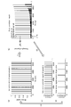
- FIG. 3 is a diagram for explaining the flow of the estimation process.
- FIG. 4 is a diagram for explaining the flow of the estimation process.
- FIG. 5 is a diagram illustrating an example of a computer that executes the estimation program.
- FIG. 1 is a schematic diagram illustrating the schematic configuration of the estimation device according to the present embodiment.
- the estimation device 10 is realized by a general-purpose computer such as a personal computer, and includes an input unit 11, an output unit 12, a communication control unit 13, a storage unit 14, and a control unit 15.
- the input unit 11 is realized by using an input device such as a keyboard and a mouse, and inputs various instruction information such as processing start to the control unit 15 in response to an input operation by an operator.
- the output unit 12 is realized by a display device such as a liquid crystal display and a printing device such as a printer.
- the communication control unit 13 is realized by a NIC (Network Interface Card) or the like, and controls communication between an external device and a control unit 15 via a telecommunication line such as a LAN (Local Area Network) or the Internet.
- a telecommunication line such as a LAN (Local Area Network) or the Internet.
- the communication control unit 13 controls communication between the control unit 15 and a management device or the like that collects and manages pulse train signals used in the estimation process described later.
- the storage unit 14 is realized by a semiconductor memory device such as a RAM (Random Access Memory) or a flash memory (Flash Memory), or a storage device such as a hard disk or an optical disk. For example, the detected period and the like are stored in the estimation process described later.
- the storage unit 14 may be configured to communicate with the control unit 15 via the communication control unit 13.
- the control unit 15 is realized by using a CPU (Central Processing Unit) or the like and executes a processing program stored in the memory. As a result, the control unit 15 functions as the aggregating unit 15a, the calculating unit 15b, the detecting unit 15c, the converting unit 15d, and the excluding unit 15e, as illustrated in FIG. Note that these functional units may be implemented individually or in a part of different hardware.
- a CPU Central Processing Unit
- the control unit 15 functions as the aggregating unit 15a, the calculating unit 15b, the detecting unit 15c, the converting unit 15d, and the excluding unit 15e, as illustrated in FIG. Note that these functional units may be implemented individually or in a part of different hardware.
- the aggregating unit 15a aggregates the input pulse train signal including time-series pulses for a predetermined observation time into a pulse for each predetermined unit time. That is, the aggregating unit 15a sets the scale of a pulse train signal (hereinafter, referred to as an input pulse train signal) for an observation time such as 3 hours, which is input as an estimation processing target by the estimation device 10, from, for example, 1 second unit. It is converted into a predetermined unit time to be described later and used as an aggregated pulse train signal.
- an input pulse train signal a pulse train signal for an observation time such as 3 hours
- the aggregating unit 15a first receives an input of a pulse train signal for a predetermined observation time via the input unit 11 or the communication control unit 13. For example, the aggregating unit 15a receives the collected packets of IP communication as the estimation processing target for each combination of (src IP, dst IP, dst port).
- the aggregating unit 15a uses the received pulse train signal for the observation time to generate an input pulse train signal that is time-series data in which the horizontal axis represents time t and the vertical axis represents the number of packets.
- the observation time is the time from the time of the first pulse generation of the input pulse train signal to the time of the last pulse generation.
- the input pulse train signal is represented by the presence and number of pulses at time t.
- the input pulse train signal is represented by a point corresponding to the number of pulses at the time when the pulse occurs, or a bar having the same number as the number of pulses indicating that the pulse has occurred (see FIG. 3A described later). ..
- the aggregating unit 15a aggregates the pulse intervals of the input pulse train signal and calculates the most frequent value. Then, the aggregating unit 15a determines the unit time based on the most frequent value of the pulse intervals of the input pulse train signal, and aggregates the input pulse train signals for each unit time. That is, the aggregating unit 15a determines the unit time by using the calculated most frequent value and converts the scale of the input pulse train signal by using the determined unit time.
- the aggregating unit 15a sets the unit time to a value that is 20% of the most frequent value of the pulse intervals of the input pulse train signal in order to absorb the deviation (jitter) of the packet generation timing. Then, the aggregating unit 15a aggregates the input pulse train signals for each determined unit time, and sets this as an aggregated pulse train signal.
- the calculation unit 15b calculates the time shift amount of the autocorrelation function using the aggregated pulse train signals that have been aggregated. Specifically, the calculation unit 15b calculates the pulse intervals of all patterns included in the aggregated pulse train signal as the time shift amount.
- the autocorrelation function is a function that measures how well the signal and the signal obtained by shifting the signal by a predetermined time shift match.
- the autocorrelation function is expressed as a function of the time shift amount ⁇ as shown in the following expression (1).
- g(t)g(t+ ⁇ ) represents the number of overlapping pulses among the number of pulses at time t and the number of pulses at time (t+ ⁇ ).
- the autocorrelation value becomes a significantly large value when the time shift amount ⁇ coincides with the period of the periodic function, and therefore can be used for estimating the period of the periodic function. Further, the pulse interval that is not included in the aggregated pulse train signal does not become a cycle. Therefore, in the present embodiment, the calculation unit 15b enumerates the pulse intervals of all patterns of the aggregated pulse train signal as the cycle candidate of the pulse train signal, and sets each as the time shift amount.
- the detection unit 15c calculates an autocorrelation value and a threshold value for each time shift amount selected in ascending order from the calculated time shift amount, and when this autocorrelation value exceeds this threshold value, this time The shift amount is detected as the period of the aggregated pulse train signal.
- the detection unit 15c selects the calculated time shift amount as a processing target in ascending order, and substitutes the selected time shift amount ⁇ in the above equation (1) to obtain the time shift amount ⁇ . Calculate the autocorrelation value.
- the detection unit 15c calculates the threshold value using a value obtained by dividing the observation time by the time shift amount ⁇ . Specifically, since the detection time of the input pulse train signal is equal to the time from the first pulse generation to the last pulse generation of the aggregated pulse train signal, the detection unit 15c uses this time as the observation time and determines this observation time. Divide by the time shift amount ⁇ .
- the autocorrelation value of the pulse train signal with respect to the time shift amount ⁇ matches the number of pulses of the period ⁇ existing in the pulse train signal.
- the value obtained by dividing the observation time by the time shift amount ⁇ is the number of pulses of the pulse train signal having the period ⁇ that should exist in the pulse train signal for the observation time. Therefore, when the pulse train signal of period ⁇ exists in the pulse train signal for the observation time, the autocorrelation value should be larger than this value.
- the detecting unit 15c calculates a value obtained by dividing the observation time by the time shift amount ⁇ by 0.8 as a threshold value. Then, when the autocorrelation value for the time shift amount ⁇ exceeds the threshold value, the detection unit 15c determines that the pulse train with the period ⁇ exists.
- the detection unit 15c has the time shift amount calculated by the calculation unit 15b next to the value to be processed. Select a smaller value and repeat the same process.
- the conversion unit 15d converts the detected cycle into the cycle of the input pulse signal input using the unit time. Specifically, the conversion unit 15d converts the value of the cycle detected by the detection unit 15c into the value of the scale of the input pulse train signal using the unit time determined by the aggregation unit 15a. Further, the conversion unit 15d stores the value of the cycle converted into the scale of the input pulse train signal in the storage unit 14 as the cycle of the detected input pulse train signal.
- the excluding unit 15e excludes the pulse train signal having the converted period from the input pulse train signal. At that time, the exclusion unit 15e calculates the most frequent value of the number of pulses for each time by summing the number of pulses for each time of the period of the converted input pulse train signal, and calculates the most frequent value from the pulse signal at each time. Exclude pulse of value.
- the exclusion unit 15e calculates the most frequent value of the number of pulses per time corresponding to this cycle as the plausible number of pulses of the converted cycle of the input pulse train signal. Then, the exclusion unit 15e excludes the calculated number of the most frequent value pulses from each time pulse. As a result, the pulse train signal having the detected period is excluded from the input pulse train signal.
- the exclusion unit 15e inputs the input pulse train signal excluding the pulse train signal of the detected cycle to the aggregating unit 15a as a new input pulse train signal.
- the estimation device 10 applies the time shift amount ⁇ in ascending order and repeats the above processing. Further, when the calculated autocorrelation value does not exceed the threshold value for all the time shift amounts ⁇ , the estimation device 10 determines that the input pulse train signal no longer has a pulse train with a period ⁇ . .. Then, the estimation apparatus 10 outputs the cycles of all the detected input pulse train signals stored in the storage unit 14 via the output unit 12 or the communication control unit 13.
- the estimation apparatus 10 detects the pulse train signal with a short cycle that can be easily distinguished from noise while sequentially focusing, and separates and detects from the input pulse train signal.
- the new input pulse train signal excluding the detected pulse train signal the noise due to the short pulse train signal is reduced, and the ratio of the number of pulses of the long pulse train signal to the input pulse train signal is increased. .. Therefore, the estimation device 10 can estimate a relatively long cycle of the pulse train signal even when the pulse train signal includes signals with a plurality of cycles having large differences in cycle.
- FIG. 2 is a flowchart showing the estimation processing procedure.
- 3 and 4 are diagrams for explaining the flow of the estimation process.
- the flowchart of FIG. 2 starts, for example, at the timing when the user inputs an operation instructing the start.
- the aggregating unit 15a receives an input of a pulse train signal including time-series pulses for a predetermined observation time via the input unit 11 or the communication control unit 13, and generates an input pulse train signal (step S1).
- the aggregating unit 15a generates an input pulse train signal in which the horizontal axis represents time t and the vertical axis represents the number of pulses, using the received pulse train signal for the observation time.
- the input pulse train signal is represented by, for example, as shown in FIG. 3A, a number of bars equal to the number of pulses indicating that a pulse is generated at the time when the pulse is generated.
- the value of the vertical axis is 1 when there is a pulse
- the value of the vertical axis is 0 when there is no pulse
- the number of pulses at time t is the pulse of which the value of the vertical axis is 1.
- the number of bars is equal to the number (one bar at any time in the illustrated example).
- the aggregating unit 15a aggregates the pulse intervals of the input pulse train signal and calculates the most frequent value. The aggregating unit 15a also determines the unit time based on the most frequent value of the pulse intervals of the input pulse train signal. Further, the aggregating unit 15a aggregates the input pulse train signals every unit time to generate an aggregated pulse train signal (step S2 in FIG. 2).
- the calculation unit 15b calculates the time shift amount of the autocorrelation function using the aggregated pulse train signal (step S3). Specifically, the calculation unit 15b calculates the pulse intervals of all patterns included in the aggregated pulse train signal as the time shift amount.
- the detection unit 15c selects the calculated time shift amount in ascending order and updates the processing target time shift amount ⁇ (step S4).
- the detection unit 15c calculates the threshold value by using the value obtained by dividing the observation time by the time shift amount ⁇ . Further, the detection unit 15c calculates an autocorrelation value with respect to the time shift amount ⁇ (steps S5 to S6 in FIG. 2, (1) in FIG. 3).
- the detection unit 15c confirms whether or not the autocorrelation value for the time shift amount ⁇ exceeds the threshold value (step S7 in FIG. 2).
- the detection unit 15c determines that a pulse train having a period ⁇ exists (step S8 in FIG. 2, FIG. 3B).
- scale conversion of the input pulse train signal by the aggregating unit 15a is not performed for simplification of description. Therefore, the processing by the conversion unit 15d described below is not performed, and the value of the period detected here is used as it is as the period of the detected input pulse train signal.
- the conversion unit 15d converts the value of the cycle detected by the detection unit 15c into the cycle of the input pulse train signal using the unit time determined by the aggregation unit 15a (step S9 in FIG. 2). Further, the conversion unit 15d stores the value of the cycle converted into the scale of the input pulse train signal in the storage unit 14 as the cycle of the detected input pulse train signal.
- the excluding unit 15e separates the converted pulse train signal of the cycle (FIG. 3(c)) and excludes it from the input pulse train signal (step S10 of FIG. 2, FIG. 3(2)).
- the pulse train signal having the period A shown in FIG. 3C is excluded from the input pulse train signal shown in FIG. 3A to obtain the pulse train signal shown in FIG. 3D.
- the exclusion unit 15e calculates the most frequent value of the number of pulses for each time by aggregating the number of pulses at each time of the period as the plausible number of pulses of the period of the converted input pulse train signal.
- the pulse with the most frequent value is excluded from the time pulse signal.
- the pulse train signal having the detected period is excluded from the input pulse train signal.
- the exclusion unit 15e inputs the input pulse train signal shown in FIG. 3(d), which excludes the pulse train signal of the detected cycle, as a new input pulse train signal to the aggregating unit 15a (step S2 in FIG. 2). , FIG. 3 (3)).
- the estimation device 10 repeats the same processing as described above, as shown in FIG.
- the calculation unit 15b calculates the time shift amount ⁇ of the autocorrelation function using the pulse train signal shown in FIG. 3D as the input pulse train signal shown in FIG. 15c calculates the threshold value and the autocorrelation value for the time shift amount ⁇ ((4) in FIG. 4).
- the exclusion unit 15e separates the pulse train signal of the detected cycle (FIG. 4(c)) and excludes it from the input pulse train signal (FIG. 4(5)).
- the exclusion unit 15e separates the pulse train signal of the detected cycle (FIG. 4(c)) and excludes it from the input pulse train signal (FIG. 4(5)).
- FIG. 4D as a result of excluding the pulse train signals of the detected period, all the pulse train signals are excluded, so that the aggregating unit 15a outputs a new input pulse train signal. Not entered.
- the estimation device 10 applies the time shift amount ⁇ in ascending order and repeats the above processing.
- the detection unit 15c calculates the calculation unit 15b. It is confirmed whether the processing has been performed for all the time shift amounts (step S11).
- step S11 If processing has not been performed for all time shift amounts (No in step S11), the detection unit 15c returns to the process of step S4 and updates the time shift amount ⁇ to be processed.
- the detection unit 15c determines that the input pulse train signal does not include the periodic pulse train any more and stores all the stored in the storage unit 14.
- the detected cycle of the input pulse train signal is output via the output unit 12 or the communication control unit 13 (step S12). This completes a series of estimation processes.
- the aggregating unit 15a aggregates the input pulse train signal including time-series pulses for a predetermined observation time into a pulse for each predetermined unit time. ..
- the calculation unit 15b calculates the time shift amount of the autocorrelation function using the aggregated pulse train signal.
- the detection unit 15c calculates an autocorrelation value and a threshold value for each time shift amount selected in ascending order from the calculated time shift amount, and when the autocorrelation value exceeds the threshold value, the time The shift amount is detected as the period of the aggregated pulse train signal.
- the conversion unit 15d converts the detected cycle into the cycle of the input pulse signal using the unit time.
- the excluding unit 15e excludes the pulse train signal having the converted period from the input pulse train signal.
- the estimation apparatus 10 detects the pulse train signal with a short cycle that is easy to distinguish from noise while sequentially focusing, and separates and detects from the input pulse train signal.
- the new input pulse train signal excluding the detected pulse train signal
- the noise due to the short pulse train signal is reduced, and the ratio of the number of pulses of the long pulse train signal to the input pulse train signal is increased. .. Therefore, the estimation device 10 can estimate the relatively long cycle of the pulse train signal even when the pulse train signal includes signals of a plurality of cycles having large differences in cycle. In this way, the estimation device 10 can accurately estimate each period of the pulse train signal including the signals of the plurality of periods.
- the estimation device 10 estimates the communication cycle of the network device in communication and counts the number of different communication cycles to determine the number of cyclic operation programs operating in the network device. It is possible to estimate.
- the estimation device 10 can detect an abnormality by detecting a change in the cycle.
- the estimation apparatus 10 can be implemented by installing an estimation program that executes the above estimation processing as package software or online software in a desired computer.
- the information processing device can be caused to function as the estimation device 10.
- the information processing device mentioned here includes a desktop or notebook personal computer.
- the information processing device includes in its category a mobile communication terminal such as a smartphone, a mobile phone, a PHS (Personal Handyphone System), and a slate terminal such as a PDA (Personal Digital Assistant).
- FIG. 5 is a diagram illustrating an example of a computer that executes an estimation program.
- the computer 1000 has, for example, a memory 1010, a CPU 1020, a hard disk drive interface 1030, a disk drive interface 1040, a serial port interface 1050, a video adapter 1060, and a network interface 1070. These units are connected by a bus 1080.
- the memory 1010 includes a ROM (Read Only Memory) 1011 and a RAM 1012.
- the ROM 1011 stores, for example, a boot program such as BIOS (Basic Input Output System).
- BIOS Basic Input Output System
- the hard disk drive interface 1030 is connected to the hard disk drive 1031.
- the disk drive interface 1040 is connected to the disk drive 1041.
- a removable storage medium such as a magnetic disk or an optical disk is inserted into the disk drive 1041.
- a mouse 1051 and a keyboard 1052 are connected to the serial port interface 1050, for example.
- a display 1061 is connected to the video adapter 1060, for example.
- the hard disk drive 1031 stores, for example, an OS 1091, an application program 1092, a program module 1093, and program data 1094. Each information described in the above embodiment is stored in, for example, the hard disk drive 1031 or the memory 1010.
- the estimation program is stored in the hard disk drive 1031 as a program module 1093 in which a command executed by the computer 1000 is described, for example.
- the program module 1093 in which each process executed by the estimation device 10 described in the above embodiment is described is stored in the hard disk drive 1031.
- data used for information processing by the estimation program is stored in the hard disk drive 1031 as the program data 1094, for example.
- the CPU 1020 reads the program module 1093 and the program data 1094 stored in the hard disk drive 1031 into the RAM 1012 as necessary, and executes the above-described procedures.
- the program module 1093 and the program data 1094 related to the estimation program are not limited to being stored in the hard disk drive 1031 and may be stored in, for example, a removable storage medium and read by the CPU 1020 via the disk drive 1041 or the like. May be done.
- the program module 1093 and the program data 1094 related to the estimation program are stored in another computer connected via a network such as LAN or WAN (Wide Area Network) and read by the CPU 1020 via the network interface 1070. May be.
Landscapes
- Engineering & Computer Science (AREA)
- Physics & Mathematics (AREA)
- General Physics & Mathematics (AREA)
- Computer Networks & Wireless Communication (AREA)
- Signal Processing (AREA)
- Mathematical Optimization (AREA)
- Theoretical Computer Science (AREA)
- Computational Mathematics (AREA)
- Mathematical Physics (AREA)
- Mathematical Analysis (AREA)
- Data Mining & Analysis (AREA)
- Pure & Applied Mathematics (AREA)
- Nonlinear Science (AREA)
- Automation & Control Theory (AREA)
- Algebra (AREA)
- Computing Systems (AREA)
- Databases & Information Systems (AREA)
- Software Systems (AREA)
- General Engineering & Computer Science (AREA)
- Radar Systems Or Details Thereof (AREA)
- Environmental & Geological Engineering (AREA)
- Complex Calculations (AREA)
- Manipulation Of Pulses (AREA)
Abstract
集約部(15a)が、入力された所定の観測時間分の時系列のパルスを含むパルス列信号を、所定の単位時間毎のパルスに集約する。算出部(15b)が、集約されたパルス列信号を用いて自己相関関数の時間シフト量を算出する。検出部(15c)が、算出された時間シフト量から昇順に選択した各時間シフト量に対する自己相関値としきい値とを算出し、該自己相関値が該しきい値を超えている場合に、該時間シフト量を集約されたパルス列信号の周期として検出する。換算部(15d)が、検出された周期を、単位時間を用いて入力されたパルス信号の周期に換算する。除外部(15e)が、換算された周期のパルス列信号を、入力されたパルス列信号から除外する。
Description
本発明は、推定装置、推定方法および推定プログラムに関する。
従来、パルス列信号の周期を推定するPRI(Pulse Repetition Intervals)変換と呼ばれる手法が知られている(非特許文献1,2参照)。PRI変換では、信号とそれ自身を時間シフトした信号とがどれだけ整合するかを図る関数であって、周期推定に広く利用される自己相関関数に、複素数で表される位相の項が加えられる。PRI変換では、パルス列信号に発生する低調波(subharmonics)と呼ばれるノイズの影響を抑制するために、複素数の項が加えられている。
Ken’ichi Nishiguchi,et al,"Improved Algorithm for Estimating Pulse Repetition Intervals", IEEE Transactions on Aerospace and Electronic Systems,2000年4月,Volume 36 issue 2,Page 407-421
Ken’ichi Nishiguchi,"Time-Period Analysis for Pulse Train Deinterleaving",Trans. of the Society of Instrument and Control Engineers,2005年,Vol.E-4,No.1,pp.68-78
しかしながら、従来の技術は、複数の周期のパルス列を含む信号の各パルス列の周期を推定することが困難な場合があった。例えば、パルス列信号の自己相関の値は、パルス列信号を時間シフトした際に元の信号と重なるパルス数の割合で決定される。したがって、周期の差が大きい複数の周期の信号がパルス列信号に含まれる場合に、周期の短い信号ほど、この周期Aだけ時間シフトした際の自己相関の値が大きくなり、容易にノイズと区別される。これに対し、このパルス列信号に含まれる周期の長い信号ほど、自己相関の値が小さくなり、ノイズとの区別が難しくなる。したがって、PRI変換では、パルス列信号に周期の差が大きい複数の周期の信号が含まれる場合に、周期の長い信号の周期を推定することが困難な場合があった。
本発明は、上記に鑑みてなされたものであって、複数の周期の信号を含むパルス列信号の各周期を精度高く推定することを目的とする。
上述した課題を解決し、目的を達成するために、本発明に係る推定装置は、入力された所定の観測時間分の時系列のパルスを含むパルス列信号を、所定の単位時間毎のパルスに集約する集約部と、集約された前記パルス列信号を用いて自己相関関数の時間シフト量を算出する算出部と、算出された前記時間シフト量から昇順に選択した各時間シフト量に対する自己相関値としきい値とを算出し、該自己相関値が該しきい値を超えている場合に、該時間シフト量を前記集約済みパルス列信号の周期として検出する検出部と、検出された前記周期を、前記単位時間を用いて入力された前記パルス列信号の周期に換算する換算部と、換算された前記周期のパルス列信号を、入力された前記パルス列信号から除外する除外部と、を備えることを特徴とする。
本発明によれば、複数の周期の信号を含むパルス列信号の各周期を精度高く推定することが可能となる。
以下、図面を参照して、本発明の一実施形態を詳細に説明する。なお、この実施形態により本発明が限定されるものではない。また、図面の記載において、同一部分には同一の符号を付して示している。
[推定装置の構成]
図1は、本実施形態の推定装置の概略構成を例示する模式図である。図1に例示するように、推定装置10は、パソコン等の汎用コンピュータで実現され、入力部11、出力部12、通信制御部13、記憶部14、および制御部15を備える。
図1は、本実施形態の推定装置の概略構成を例示する模式図である。図1に例示するように、推定装置10は、パソコン等の汎用コンピュータで実現され、入力部11、出力部12、通信制御部13、記憶部14、および制御部15を備える。
入力部11は、キーボードやマウス等の入力デバイスを用いて実現され、操作者による入力操作に対応して、制御部15に対して処理開始などの各種指示情報を入力する。出力部12は、液晶ディスプレイなどの表示装置、プリンター等の印刷装置等によって実現される。
通信制御部13は、NIC(Network Interface Card)等で実現され、LAN(Local Area Network)やインターネットなどの電気通信回線を介した外部の装置と制御部15との通信を制御する。例えば、通信制御部13は、後述する推定処理に用いられるパルス列信号を収集し管理する管理装置等と制御部15との通信を制御する。
記憶部14は、RAM(Random Access Memory)、フラッシュメモリ(Flash Memory)等の半導体メモリ素子、または、ハードディスク、光ディスク等の記憶装置によって実現される。例えば、後述する推定処理において、検出された周期等が記憶される。なお、記憶部14は、通信制御部13を介して制御部15と通信する構成でもよい。
制御部15は、CPU(Central Processing Unit)等を用いて実現され、メモリに記憶された処理プログラムを実行する。これにより、制御部15は、図1に例示するように、集約部15a、算出部15b、検出部15c、換算部15dおよび除外部15eとして機能する。なお、これらの機能部は、それぞれ、あるいは一部が異なるハードウェアに実装されてもよい。
集約部15aは、入力された所定の観測時間分の時系列のパルスを含むパルス列信号を、所定の単位時間毎のパルスに集約する。すなわち、集約部15aは、推定装置10による推定処理対象として入力された、例えば3時間分等の観測時間分のパルス列信号(以下、入力パルス列信号と記す。)のスケールを、例えば1秒単位から後述する所定の単位時間に変換し、集約済みパルス列信号とする。
具体的には、集約部15aは、まず、入力部11あるいは通信制御部13を介して、所定の観測時間分のパルス列信号の入力を受け付ける。例えば、集約部15aは、収集されたIP通信のパケットを、(src IP、dst IP、dst port)の組み合わせごとに推定処理対象として受け付ける。
また、集約部15aは、受け付けた観測時間分のパルス列信号を用いて、横軸を時刻t、縦軸をパケット数とする時系列データである入力パルス列信号を生成する。ここで、観測時間は、入力されたパルス列信号の最初のパルス発生の時刻から最後のパルス発生の時刻までの時間である。また、入力パルス列信号は、時刻tにおけるパルスの有無とその数とで表される。例えば、入力パルス列信号は、パルスが発生した時刻におけるパルス数に相当する点、あるいはパルスが発生したことを示す、パルス数に等しい本数の棒で表される(後述する図3(a)参照)。
次に、集約部15aは、入力パルス列信号のパルス間隔を集計し、最頻出値を算出する。そして、集約部15aは、入力パルス列信号のパルス間隔の最頻出値に基づいて単位時間を決定し、該単位時間毎に入力パルス列信号を集約する。すなわち、集約部15aは、算出した最頻出値を用いて単位時間を決定し、決定した単位時間を用いて入力パルス列信号のスケールを変換する。
本実施形態では、集約部15aは、パケット発生のタイミングのずれ(jitter)を吸収するために、入力パルス列信号のパルス間隔の最頻出値の20%の値を単位時間とする。そして、集約部15aは、決定した単位時間毎に入力パルス列信号を集約し、これを集約済みパルス列信号とする。
算出部15bは、集約された集約済みパルス列信号を用いて自己相関関数の時間シフト量を算出する。具体的には、算出部15bは、集約済みパルス列信号に含まれる全てのパターンのパルス間隔を、時間シフト量として算出する。
ここで、上記のとおり、自己相関関数は、信号とそれ自身を所定の時間シフト量だけシフトした信号とがどれだけ整合するかを図る関数である。自己相関関数は、次式(1)に示すように、時間シフト量τの関数として表される。

ここで、g(t)g(t+τ)は、時刻tのパルス数と時刻(t+τ)のパルス数とのうち、重複しているパルス数を表す。
上記式(1)に示すように、自己相関値は、時間シフト量τが周期関数の周期と一致した場合に有意に大きな値となるので、周期関数の周期の推定に利用できる。また、集約済みパルス列信号にないパルス間隔が周期となることはない。そこで、本実施形態では、算出部15bが、パルス列信号の周期候補として、集約済みパルス列信号の全てのパターンのパルス間隔を列挙して、それぞれを時間シフト量とする。
検出部15cは、算出された時間シフト量から昇順に選択した各時間シフト量に対する自己相関値としきい値とを算出し、この自己相関値がこのしきい値を超えている場合に、この時間シフト量を集約されたパルス列信号の周期として検出する。
具体的には、検出部15cは、算出された時間シフト量を昇順に処理対象として選択して、選択した時間シフト量τを上記式(1)に代入することにより、この時間シフト量τに対する自己相関値を算出する。
また、検出部15cは、観測時間を時間シフト量τで除算した値を用いてしきい値を算出する。具体的には、検出部15cは、入力パルス列信号の観測時間は、集約済みパルス列信号の最初のパルス発生から最後のパルス発生までの時間に等しいので、この時間を観測時間として、この観測時間を時間シフト量τで除算する。
ここで、上記式(1)からわかるように、時間シフト量τに対するパルス列信号の自己相関値は、パルス列信号内に存在する周期τのパルス数と一致する。また、観測時間を時間シフト量τで除算した値は、観測時間分のパルス列信号内に存在するはずの周期τのパルス列信号のパルス回数となる。したがって、観測時間分のパルス列信号内に周期τのパルス列信号が存在する場合には、自己相関値はこの値より大きくなるはずである。
そこで、検出部15cは、パルスの欠損を2割まで許容する場合に、観測時間を時間シフト量τで除算した値に0.8を乗算した値をしきい値として算出する。そして、検出部15cは、時間シフト量τに対する自己相関値がしきい値を超えている場合に、周期τのパルス列が存在すると判定する。
また、検出部15cは、時間シフト量τに対する自己相関値がしきい値を超えていない場合には、算出部15bにより算出された時間シフト量のうち、上記の処理対象とした値の次に小さい値を選択し、同様の処理を繰り返す。
換算部15dは、検出された周期を、単位時間を用いて入力された入力パルス信号の周期に換算する。具体的には、換算部15dは、検出部15cが検出した周期の値を、集約部15aが決定した単位時間を用いて入力パルス列信号のスケールの値に換算する。また、換算部15dは、入力パルス列信号のスケールに換算した周期の値を、検出済みの入力パルス列信号の周期として記憶部14に記憶させる。
除外部15eは、換算された周期のパルス列信号を、入力パルス列信号から除外する。その際に、除外部15eは、換算された入力パルス列信号の周期の時刻ごとにパルス数を集計して各時刻あたりのパルス数の最頻出値を算出し、各時刻のパルス信号から該最頻出値のパルスを除外する。
すなわち、除外部15eは、換算された入力パルス列信号の周期のもっともらしいパルス数として、この周期に該当する各時刻あたりのパルス数の最頻出値を算出する。そして、除外部15eは、各時刻のパルスから、算出した最頻出値の数のパルスを除外する。これにより、入力パルス列信号から検出済みの周期のパルス列信号が除外される。
また、除外部15eは、検出済みの周期のパルス列信号を除外した入力パルス列信号を、新たな入力パルス列信号として集約部15aに入力する。
このようにして、推定装置10は、時間シフト量τを小さい順に適用して、上記の処理を繰り返す。また、推定装置10は、全ての時間シフト量τに対して、算出した自己相関値がしきい値を超えなくなった場合に、入力パルス列信号にはもはや周期τのパルス列が存在しないものと判定する。そして、推定装置10は、記憶部14に記憶させた全ての検出済みの入力パルス列信号の周期を、出力部12あるいは通信制御部13を介して出力する。
これにより、推定装置10は、ノイズとの区別が容易な周期の短いパルス列信号から順に焦点を当てながら検出し、入力パルス列信号から分離し除外する。検出済みの周期のパルス列信号が除外された新たな入力パルス列信号では、周期の短いパルス列信号に起因するノイズが低減され、また入力パルス列信号に占める周期の長いパルス列信号のパルス数の割合が増大する。したがって、推定装置10は、パルス列信号に周期の差が大きい複数の周期の信号が含まれる場合にも、パルス列信号の相対的に長い周期を推定することが可能となる。
[推定処理]
次に、図2~4を参照して、本実施形態に係る推定装置10による推定処理について説明する。図2は、推定処理手順を示すフローチャートである。また、図3および図4は、推定処理の流れを説明するための図である。
次に、図2~4を参照して、本実施形態に係る推定装置10による推定処理について説明する。図2は、推定処理手順を示すフローチャートである。また、図3および図4は、推定処理の流れを説明するための図である。
図2のフローチャートは、例えば、ユーザが開始を指示する操作入力を行ったタイミングで開始される。まず、集約部15aが、入力部11あるいは通信制御部13を介して、所定の観測時間分の時系列のパルスを含むパルス列信号の入力を受け付けて、入力パルス列信号を生成する(ステップS1)。例えば、集約部15aは、受け付けた観測時間分のパルス列信号を用いて、横軸を時刻t、縦軸をパルス数とする入力パルス列信号を生成する。
入力パルス列信号は、例えば、図3(a)に示すように、パルスが発生した時刻においてパルスが発生していることを示す、パルス数に等しい本数の棒で表される。図3(a)に示す例では、パルスがある場合に縦軸の値は1、パルスがない場合に縦軸の値は0として、時刻tのパルス数が、縦軸の値が1のパルス数に等しい本数の棒(図示例では、いずれの時刻でも1本)で表されている。
次に、集約部15aは、入力パルス列信号のパルス間隔を集計し、最頻出値を算出する。また、集約部15aは、入力パルス列信号のパルス間隔の最頻出値に基づいて単位時間を決定する。また、集約部15aは、単位時間毎に入力パルス列信号を集約することにより、集約済みパルス列信号を生成する(図2のステップS2)。
次に、算出部15bが、集約済みパルス列信号を用いて自己相関関数の時間シフト量を算出する(ステップS3)。具体的には、算出部15bは、集約済みパルス列信号に含まれる全てのパターンのパルス間隔を、時間シフト量として算出する。
次に、検出部15cが、算出された時間シフト量を昇順に選択して処理対象の時間シフト量τを更新する(ステップS4)。
そして、検出部15cは、観測時間を時間シフト量τで除算した値を用いてしきい値を算出する。また、検出部15cは、時間シフト量τに対する自己相関値を算出する(図2のステップS5~S6、図3の(1))。
そして、検出部15cは、時間シフト量τに対する自己相関値がしきい値を超えているか否かを確認する(図2のステップS7)。検出部15cは、自己相関値がしきい値を超えている場合に(ステップS7,Yes)、周期τのパルス列が存在すると判定する(図2のステップS8、図3(b))。
図3(b)に示す例では、τ=Aが周期として検出されている。なお、図3および図4に示す例では、説明の簡略化のため、集約部15aによる入力パルス列信号のスケール変換は行われていない。したがって、以下に述べる換算部15dによる処理は行われず、ここで検出された周期の値がそのまま、検出済みの入力パルス列信号の周期とされている。
換算部15dは、検出部15cが検出した周期の値を、集約部15aが決定した単位時間を用いて、入力パルス列信号の周期に換算する(図2のステップS9)。また、換算部15dは、入力パルス列信号のスケールに換算した周期の値を、検出済みの入力パルス列信号の周期として記憶部14に記憶させる。
次に、除外部15eが、換算された該周期のパルス列信号を分離して(図3(c))、入力パルス列信号から除外する(図2のステップS10、図3(2))。図3に示す例では、図3(c)に示す周期Aのパルス列信号が、図3(a)に示す入力パルス列信号から除外され、図3(d)に示すパルス列信号とされている。
その際に、除外部15eは、換算された入力パルス列信号の周期のもっともらしいパルス数として、周期の時刻ごとにパルス数を集計して各時刻あたりのパルス数の最頻出値を算出し、各時刻のパルス信号から最頻出値のパルスを除外する。これにより、入力パルス列信号から検出済みの周期のパルス列信号が除外される。
また、除外部15eは、検出済みの周期のパルス列信号を除外した、図3(d)に示した入力パルス列信号を、新たな入力パルス列信号として、集約部15aに入力する(図2のステップS2、図3(3))。
そして、推定装置10は、図4に示すように、上記と同様の処理を繰り返す。図4に示す例では、図3(d)に示したパルス列信号を、図4(a)に示す入力パルス列信号として、算出部15bが、自己相関関数の時間シフト量τを算出し、検出部15cが、時間シフト量τに対するしきい値と自己相関値とを算出する(図4(4))。
そして、検出部15cが、時間シフト量τに対する自己相関値がしきい値を超えている場合に、検出部15cが、周期τのパルス列が存在すると判定する。図4(b)に示す例では、τ=Bが周期として検出されている。
そして、除外部15eが、検出された周期のパルス列信号を分離して(図4(c))、入力パルス列信号から除外する(図4(5))。図4に示す例では、図4(d)に示すように、検出済みの周期のパルス列信号を除外した結果、すべてのパルス列信号が除外されているため、新たな入力パルス列信号として集約部15aに入力されていない。
このようにして、推定装置10は、時間シフト量τを小さい順に適用して、上記の処理を繰り返す。なお、上記した図2のステップS7の処理において、時間シフト量τに対する自己相関値がしきい値を超えなかった場合には(ステップS7,No)、検出部15cは、算出部15bが算出した全ての時間シフト量について処理が行われたかを確認する(ステップS11)。
全ての時間シフト量について処理が行われていない場合には(ステップS11,No)、検出部15cは、ステップS4の処理に戻し、処理対象の時間シフト量τを更新する。全ての時間シフト量について処理が行われている場合には(ステップS11,Yes)、検出部15cは、入力パルス列信号にはもはや周期パルス列が存在しないものとして、記憶部14に記憶させた全ての検出済みの入力パルス列信号の周期を、出力部12あるいは通信制御部13を介して出力する(ステップS12)。これにより、一連の推定処理が終了する。
以上、説明したように、本実施形態の推定装置10において、集約部15aが、入力された所定の観測時間分の時系列のパルスを含むパルス列信号を、所定の単位時間毎のパルスに集約する。算出部15bが、集約されたパルス列信号を用いて自己相関関数の時間シフト量を算出する。検出部15cが、算出された時間シフト量から昇順に選択した各時間シフト量に対する自己相関値としきい値とを算出し、該自己相関値が該しきい値を超えている場合に、該時間シフト量を集約されたパルス列信号の周期として検出する。換算部15dが、検出された周期を、単位時間を用いて入力されたパルス信号の周期に換算する。除外部15eが、換算された周期のパルス列信号を、入力されたパルス列信号から除外する。
これにより、推定装置10は、ノイズとの区別が容易な周期の短いパルス列信号から順に焦点を当てながら検出し、入力パルス列信号から分離し除外する。検出済みの周期のパルス列信号が除外された新たな入力パルス列信号では、周期の短いパルス列信号に起因するノイズが低減され、また入力パルス列信号に占める周期の長いパルス列信号のパルス数の割合が増大する。したがって、推定装置10は、パルス列信号に周期の差が大きい複数の周期の信号が含まれる場合にも、パルス列信号の相対的に長い周期を推定することが可能となる。このように、推定装置10は、推定装置10は、複数の周期の信号を含むパルス列信号の各周期を精度高く推定することができる。
例えば、ビルや工場等のOT(Operational Technology)環境において、多数の機器が事前に定義されたプログラムのみに基づいて、一定時間ごとに死活確認や機器状態の確認等の周期的な動作を行う場合が多い。そのような環境で、推定装置10は、通信中のネットワーク機器の通信周期を推定し、異なる通信周期の数を計上することにより、ネットワーク機器内で動作している周期的な動作プログラムの数を推定することが可能となる。また、推定装置10は、周期の変化を検出することにより、異常を検知することも可能となる。
[プログラム]
上記実施形態に係る推定装置10が実行する処理をコンピュータが実行可能な言語で記述したプログラムを作成することもできる。一実施形態として、推定装置10は、パッケージソフトウェアやオンラインソフトウェアとして上記の推定処理を実行する推定プログラムを所望のコンピュータにインストールさせることによって実装できる。例えば、上記の推定プログラムを情報処理装置に実行させることにより、情報処理装置を推定装置10として機能させることができる。ここで言う情報処理装置には、デスクトップ型またはノート型のパーソナルコンピュータが含まれる。また、その他にも、情報処理装置にはスマートフォン、携帯電話機やPHS(Personal Handyphone System)などの移動体通信端末、さらには、PDA(Personal Digital Assistant)などのスレート端末などがその範疇に含まれる。また、推定装置10の機能を、クラウドサーバに実装してもよい。
上記実施形態に係る推定装置10が実行する処理をコンピュータが実行可能な言語で記述したプログラムを作成することもできる。一実施形態として、推定装置10は、パッケージソフトウェアやオンラインソフトウェアとして上記の推定処理を実行する推定プログラムを所望のコンピュータにインストールさせることによって実装できる。例えば、上記の推定プログラムを情報処理装置に実行させることにより、情報処理装置を推定装置10として機能させることができる。ここで言う情報処理装置には、デスクトップ型またはノート型のパーソナルコンピュータが含まれる。また、その他にも、情報処理装置にはスマートフォン、携帯電話機やPHS(Personal Handyphone System)などの移動体通信端末、さらには、PDA(Personal Digital Assistant)などのスレート端末などがその範疇に含まれる。また、推定装置10の機能を、クラウドサーバに実装してもよい。
図5は、推定プログラムを実行するコンピュータの一例を示す図である。コンピュータ1000は、例えば、メモリ1010と、CPU1020と、ハードディスクドライブインタフェース1030と、ディスクドライブインタフェース1040と、シリアルポートインタフェース1050と、ビデオアダプタ1060と、ネットワークインタフェース1070とを有する。これらの各部は、バス1080によって接続される。
メモリ1010は、ROM(Read Only Memory)1011およびRAM1012を含む。ROM1011は、例えば、BIOS(Basic Input Output System)等のブートプログラムを記憶する。ハードディスクドライブインタフェース1030は、ハードディスクドライブ1031に接続される。ディスクドライブインタフェース1040は、ディスクドライブ1041に接続される。ディスクドライブ1041には、例えば、磁気ディスクや光ディスク等の着脱可能な記憶媒体が挿入される。シリアルポートインタフェース1050には、例えば、マウス1051およびキーボード1052が接続される。ビデオアダプタ1060には、例えば、ディスプレイ1061が接続される。
ここで、ハードディスクドライブ1031は、例えば、OS1091、アプリケーションプログラム1092、プログラムモジュール1093およびプログラムデータ1094を記憶する。上記実施形態で説明した各情報は、例えばハードディスクドライブ1031やメモリ1010に記憶される。
また、推定プログラムは、例えば、コンピュータ1000によって実行される指令が記述されたプログラムモジュール1093として、ハードディスクドライブ1031に記憶される。具体的には、上記実施形態で説明した推定装置10が実行する各処理が記述されたプログラムモジュール1093が、ハードディスクドライブ1031に記憶される。
また、推定プログラムによる情報処理に用いられるデータは、プログラムデータ1094として、例えば、ハードディスクドライブ1031に記憶される。そして、CPU1020が、ハードディスクドライブ1031に記憶されたプログラムモジュール1093やプログラムデータ1094を必要に応じてRAM1012に読み出して、上述した各手順を実行する。
なお、推定プログラムに係るプログラムモジュール1093やプログラムデータ1094は、ハードディスクドライブ1031に記憶される場合に限られず、例えば、着脱可能な記憶媒体に記憶されて、ディスクドライブ1041等を介してCPU1020によって読み出されてもよい。あるいは、推定プログラムに係るプログラムモジュール1093やプログラムデータ1094は、LANやWAN(Wide Area Network)等のネットワークを介して接続された他のコンピュータに記憶され、ネットワークインタフェース1070を介してCPU1020によって読み出されてもよい。
以上、本発明者によってなされた発明を適用した実施形態について説明したが、本実施形態による本発明の開示の一部をなす記述および図面により本発明は限定されることはない。すなわち、本実施形態に基づいて当業者等によりなされる他の実施形態、実施例および運用技術等は全て本発明の範疇に含まれる。
10 推定装置
11 入力部
12 出力部
13 通信制御部
14 記憶部
15 制御部
15a 集約部
15b 算出部
15c 検出部
15d 換算部
15e 除外部
11 入力部
12 出力部
13 通信制御部
14 記憶部
15 制御部
15a 集約部
15b 算出部
15c 検出部
15d 換算部
15e 除外部
Claims (7)
- 入力された所定の観測時間分の時系列のパルスを含むパルス列信号を、所定の単位時間毎のパルスに集約する集約部と、
集約された前記パルス列信号を用いて自己相関関数の時間シフト量を算出する算出部と、
算出された前記時間シフト量から昇順に選択した各時間シフト量に対する自己相関値としきい値とを算出し、該自己相関値が該しきい値を超えている場合に、該時間シフト量を集約された前記パルス列信号の周期として検出する検出部と、
検出された前記周期を、前記単位時間を用いて入力された前記パルス列信号の周期に換算する換算部と、
換算された前記周期のパルス列信号を、入力された前記パルス列信号から除外する除外部と、
を備えることを特徴とする推定装置。 - 前記集約部は、入力された前記パルス列信号のパルス間隔の最頻出値に基づいて前記単位時間を決定し、該単位時間毎に入力された前記パルス列信号を集約することを特徴とする請求項1に記載の推定装置。
- 前記算出部は、集約された前記パルス列信号に含まれる全てのパターンのパルス間隔を、前記時間シフト量として算出することを特徴とする請求項1に記載の推定装置。
- 前記検出部は、前記観測時間を前記時間シフト量で除算した値を用いて前記しきい値を算出することを特徴とする請求項1に記載の推定装置。
- 前記除外部は、換算された前記周期の時刻ごとにパルス数を集計して各時刻のパルス数の最頻出値を算出し、各時刻のパルスから該最頻出値の数のパルスを除外することを特徴とする請求項1に記載の推定装置。
- 推定装置で実行される推定方法であって、
入力された所定の観測時間分の時系列のパルスを含むパルス列信号を、所定の単位時間毎のパルスに集約する集約工程と、
集約された前記パルス列信号を用いて自己相関関数の時間シフト量を算出する算出工程と、
算出された前記時間シフト量から昇順に選択した各時間シフト量に対する自己相関値としきい値とを算出し、該自己相関値が該しきい値を超えている場合に、該時間シフト量を集約された前記パルス列信号の周期として検出する検出工程と、
検出された前記周期を、前記単位時間を用いて入力された前記パルス列信号の周期に換算する換算工程と、
換算された前記周期のパルス列信号を入力された前記パルス列信号から除外する除外工程と、
を含んだことを特徴とする推定方法。 - 入力された所定の観測時間分の時系列のパルスを含むパルス列信号を、所定の単位時間毎のパルスに集約する集約ステップと、
集約された前記パルス列信号を用いて自己相関関数の時間シフト量を算出する算出ステップと、
算出された前記時間シフト量から昇順に選択した各時間シフト量に対する自己相関値としきい値とを算出し、該自己相関値が該しきい値を超えている場合に、該時間シフト量を集約された前記パルス列信号の周期として検出する検出ステップと、
検出された前記周期を、前記単位時間を用いて入力された前記パルス列信号の周期に換算する換算ステップと、
換算された前記周期のパルス列信号を、入力された前記パルス列信号から除外する除外ステップと、
をコンピュータに実行させる推定プログラム。
Priority Applications (1)
| Application Number | Priority Date | Filing Date | Title |
|---|---|---|---|
| US17/288,238 US11909619B2 (en) | 2018-12-13 | 2019-11-13 | Estimation device, estimation method and estimation program |
Applications Claiming Priority (2)
| Application Number | Priority Date | Filing Date | Title |
|---|---|---|---|
| JP2018233810A JP7031573B2 (ja) | 2018-12-13 | 2018-12-13 | 推定装置、推定方法および推定プログラム |
| JP2018-233810 | 2018-12-13 |
Publications (1)
| Publication Number | Publication Date |
|---|---|
| WO2020121722A1 true WO2020121722A1 (ja) | 2020-06-18 |
Family
ID=71077237
Family Applications (1)
| Application Number | Title | Priority Date | Filing Date |
|---|---|---|---|
| PCT/JP2019/044519 Ceased WO2020121722A1 (ja) | 2018-12-13 | 2019-11-13 | 推定装置、推定方法および推定プログラム |
Country Status (3)
| Country | Link |
|---|---|
| US (1) | US11909619B2 (ja) |
| JP (1) | JP7031573B2 (ja) |
| WO (1) | WO2020121722A1 (ja) |
Families Citing this family (1)
| Publication number | Priority date | Publication date | Assignee | Title |
|---|---|---|---|---|
| US11449588B2 (en) * | 2019-03-18 | 2022-09-20 | Lg Electronics Inc. | Electronic device and method for controlling the same |
Citations (2)
| Publication number | Priority date | Publication date | Assignee | Title |
|---|---|---|---|---|
| JP2012157212A (ja) * | 2011-01-28 | 2012-08-16 | Toyota Industries Corp | インバータ装置 |
| JP2013038592A (ja) * | 2011-08-08 | 2013-02-21 | Mitsubishi Electric Corp | 信号分離装置及び信号分離方法 |
Family Cites Families (2)
| Publication number | Priority date | Publication date | Assignee | Title |
|---|---|---|---|---|
| JP4776610B2 (ja) * | 2007-11-26 | 2011-09-21 | 三菱電機株式会社 | 監視制御回路を有する車載電子制御装置 |
| JP7151561B2 (ja) * | 2019-03-08 | 2022-10-12 | 日本電信電話株式会社 | パルス列信号の周期推定装置、パルス列信号の周期推定方法およびパルス列信号の周期推定プログラム |
-
2018
- 2018-12-13 JP JP2018233810A patent/JP7031573B2/ja active Active
-
2019
- 2019-11-13 WO PCT/JP2019/044519 patent/WO2020121722A1/ja not_active Ceased
- 2019-11-13 US US17/288,238 patent/US11909619B2/en active Active
Patent Citations (2)
| Publication number | Priority date | Publication date | Assignee | Title |
|---|---|---|---|---|
| JP2012157212A (ja) * | 2011-01-28 | 2012-08-16 | Toyota Industries Corp | インバータ装置 |
| JP2013038592A (ja) * | 2011-08-08 | 2013-02-21 | Mitsubishi Electric Corp | 信号分離装置及び信号分離方法 |
Non-Patent Citations (2)
| Title |
|---|
| NISHIGUCHI, KEN'ICHI: "Time-Period Analysis for Pulse Train Deinterleaving", TRANSACTIONS OF THE SOCIETY OF INSTRUMENT AND CONTROL ENGINEERS, vol. 40, no. 11, 30 November 2004 (2004-11-30), pages 1114 - 1123, ISSN: 1883-8189, Retrieved from the Internet <URL:https://www.jstage.jst.go.jp/article/sicetr1965/40/11/40_11_1114/-article/-char/ja> [retrieved on 20200129] * |
| SUN, HAIBIN ET AL.: "Defending against low-rate TCP attacks: dynamic detection and protection", PROCEEDINGS OF THE 12TH IEEE INTERNATIONAL CONFERENCE ON NETWORK PROTOCOLS, 1 November 2004 (2004-11-01), XP010734822, ISSN: 1092-1648, Retrieved from the Internet <URL:https://ieeexplore.ieee.org/abstract/document/1348110> [retrieved on 20200129] * |
Also Published As
| Publication number | Publication date |
|---|---|
| US20210392067A1 (en) | 2021-12-16 |
| US11909619B2 (en) | 2024-02-20 |
| JP2020095540A (ja) | 2020-06-18 |
| JP7031573B2 (ja) | 2022-03-08 |
Similar Documents
| Publication | Publication Date | Title |
|---|---|---|
| CN109978055B (zh) | 多传感器系统的信息融合方法及系统、计算机设备及介质 | |
| RU2451328C1 (ru) | Адаптивное цифровое прогнозирующее устройство | |
| RU2450343C1 (ru) | Цифровое прогнозирующее и дифференцирующее устройство | |
| WO2014120390A1 (en) | Methods and systems for online monitoring using a variable data sampling rate | |
| EP4202800B1 (en) | Learning device, learning method, and learning program | |
| RU2455682C1 (ru) | Цифровое прогнозирующее устройство | |
| JP7359229B2 (ja) | 検知装置、検知方法および検知プログラム | |
| JP7031573B2 (ja) | 推定装置、推定方法および推定プログラム | |
| EP3934175B1 (en) | Anomaly detection method and anomaly detection program | |
| US11663191B2 (en) | Method, device and computer program product for managing log | |
| JP2014211330A (ja) | 目標追尾装置及び目標追尾方法 | |
| JP2000044135A (ja) | エレベータにおける速度制御装置およびエレベータの速度検出プログラムを記録した記録媒体 | |
| RU2517316C1 (ru) | Адаптивное цифровое прогнозирующее устройство | |
| RU2517322C1 (ru) | Адаптивное цифровое прогнозирующее и дифференцирующее устройство | |
| RU2517317C1 (ru) | Адаптивное цифровое прогнозирующее и дифференцирующее устройство | |
| RU2477887C1 (ru) | Цифровое прогнозирующее устройство | |
| CA2988634A1 (en) | System and method for event detection using streaming signals | |
| RU2470359C1 (ru) | Цифровое прогнозирующее и дифференцирующее устройство | |
| RU2622852C1 (ru) | Адаптивное цифровое сглаживающее и прогнозирующее устройство | |
| US11365962B2 (en) | Filtering device, sensor device, filtering method and program | |
| WO2018014631A1 (zh) | 一种峰值功率、峰均值功率比的确定方法及装置 | |
| RU2535467C1 (ru) | Адаптивное цифровое дифференцирующее и прогнозирующее устройство | |
| US11349634B2 (en) | Cycle estimation device for pulse train signal, cycle estimation method for pulse train signal, and cycle estimation program for pulse train signal | |
| JP5376395B2 (ja) | 波形測定装置 | |
| RU2626338C1 (ru) | Адаптивное цифровое сглаживающее и прогнозирующее устройство |
Legal Events
| Date | Code | Title | Description |
|---|---|---|---|
| 121 | Ep: the epo has been informed by wipo that ep was designated in this application |
Ref document number: 19897476 Country of ref document: EP Kind code of ref document: A1 |
|
| NENP | Non-entry into the national phase |
Ref country code: DE |
|
| 122 | Ep: pct application non-entry in european phase |
Ref document number: 19897476 Country of ref document: EP Kind code of ref document: A1 |