WO2020121422A1 - Management index calculation system and management index calculation method - Google Patents
Management index calculation system and management index calculation method Download PDFInfo
- Publication number
- WO2020121422A1 WO2020121422A1 PCT/JP2018/045577 JP2018045577W WO2020121422A1 WO 2020121422 A1 WO2020121422 A1 WO 2020121422A1 JP 2018045577 W JP2018045577 W JP 2018045577W WO 2020121422 A1 WO2020121422 A1 WO 2020121422A1
- Authority
- WO
- WIPO (PCT)
- Prior art keywords
- data
- management index
- equipment
- production
- format
- Prior art date
Links
- 238000004364 calculation method Methods 0.000 title claims abstract description 99
- 238000007726 management method Methods 0.000 claims abstract description 138
- 238000004519 manufacturing process Methods 0.000 claims abstract description 124
- 238000012545 processing Methods 0.000 claims abstract description 41
- 238000013500 data storage Methods 0.000 claims abstract description 22
- 238000003860 storage Methods 0.000 claims description 28
- 230000008520 organization Effects 0.000 claims description 4
- 238000006243 chemical reaction Methods 0.000 claims description 2
- 238000011156 evaluation Methods 0.000 claims 1
- 230000006870 function Effects 0.000 description 35
- 238000000034 method Methods 0.000 description 26
- 230000008859 change Effects 0.000 description 19
- 238000010586 diagram Methods 0.000 description 17
- 230000008569 process Effects 0.000 description 14
- 239000000284 extract Substances 0.000 description 10
- 230000010365 information processing Effects 0.000 description 9
- 238000004891 communication Methods 0.000 description 7
- 230000002950 deficient Effects 0.000 description 7
- 238000012360 testing method Methods 0.000 description 5
- 238000002360 preparation method Methods 0.000 description 4
- 238000013480 data collection Methods 0.000 description 3
- 230000008878 coupling Effects 0.000 description 2
- 238000010168 coupling process Methods 0.000 description 2
- 238000005859 coupling reaction Methods 0.000 description 2
- 230000002159 abnormal effect Effects 0.000 description 1
- 238000004458 analytical method Methods 0.000 description 1
- 230000005540 biological transmission Effects 0.000 description 1
- 230000003247 decreasing effect Effects 0.000 description 1
- 230000000694 effects Effects 0.000 description 1
- 238000000605 extraction Methods 0.000 description 1
- 230000010354 integration Effects 0.000 description 1
- 208000018910 keratinopathic ichthyosis Diseases 0.000 description 1
- 239000004973 liquid crystal related substance Substances 0.000 description 1
- 238000012423 maintenance Methods 0.000 description 1
- 238000005259 measurement Methods 0.000 description 1
- 230000004044 response Effects 0.000 description 1
- 239000010865 sewage Substances 0.000 description 1
- XLYOFNOQVPJJNP-UHFFFAOYSA-N water Substances O XLYOFNOQVPJJNP-UHFFFAOYSA-N 0.000 description 1
Images


Classifications
-
- G—PHYSICS
- G05—CONTROLLING; REGULATING
- G05B—CONTROL OR REGULATING SYSTEMS IN GENERAL; FUNCTIONAL ELEMENTS OF SUCH SYSTEMS; MONITORING OR TESTING ARRANGEMENTS FOR SUCH SYSTEMS OR ELEMENTS
- G05B19/00—Programme-control systems
- G05B19/02—Programme-control systems electric
- G05B19/418—Total factory control, i.e. centrally controlling a plurality of machines, e.g. direct or distributed numerical control [DNC], flexible manufacturing systems [FMS], integrated manufacturing systems [IMS] or computer integrated manufacturing [CIM]
-
- G—PHYSICS
- G05—CONTROLLING; REGULATING
- G05B—CONTROL OR REGULATING SYSTEMS IN GENERAL; FUNCTIONAL ELEMENTS OF SUCH SYSTEMS; MONITORING OR TESTING ARRANGEMENTS FOR SUCH SYSTEMS OR ELEMENTS
- G05B23/00—Testing or monitoring of control systems or parts thereof
- G05B23/02—Electric testing or monitoring
-
- Y—GENERAL TAGGING OF NEW TECHNOLOGICAL DEVELOPMENTS; GENERAL TAGGING OF CROSS-SECTIONAL TECHNOLOGIES SPANNING OVER SEVERAL SECTIONS OF THE IPC; TECHNICAL SUBJECTS COVERED BY FORMER USPC CROSS-REFERENCE ART COLLECTIONS [XRACs] AND DIGESTS
- Y02—TECHNOLOGIES OR APPLICATIONS FOR MITIGATION OR ADAPTATION AGAINST CLIMATE CHANGE
- Y02P—CLIMATE CHANGE MITIGATION TECHNOLOGIES IN THE PRODUCTION OR PROCESSING OF GOODS
- Y02P90/00—Enabling technologies with a potential contribution to greenhouse gas [GHG] emissions mitigation
- Y02P90/02—Total factory control, e.g. smart factories, flexible manufacturing systems [FMS] or integrated manufacturing systems [IMS]
Definitions
- the present invention relates to a management index calculation system and a management index calculation method for calculating a management index.
- a data collection device arranged for each production facility collects data from the production facility based on a definition file in which a data collection method is defined, and produces from the collected data. Event data indicating a change in the state of equipment is generated and supplied to a remote center device, and the remote center device performs analysis processing and the like.
- the number of setting items collected from the production equipment by each data collecting device is the same, so that the format of the data packet output by each data collecting device to the remote center device is determined. It is unified.
- Patent Document 1 described above, if the type or format of the data accumulated by the supervisory control system that monitors and controls the water and sewage facilities is different, a separate definition file is set for each data collection device, and It was necessary to set a conversion process for generating event data from the collected data for each supervisory control system. Therefore, the technique of Patent Document 1 cannot easily calculate the management index for a plurality of production facilities.
- the present invention has been made in view of the above, and an object thereof is to obtain a management index calculation system that can easily calculate a management index for a plurality of production facilities.
- the management index calculation system of the present invention includes a plurality of production facilities including a device and a control device for controlling the device.
- the management index calculation system collects the equipment data generated from each of the plurality of production equipment in the first data format that is unified among the plurality of production equipment to generate the plurality of production equipment.
- the first data format with the processing logic common to each of the equipment data collected from the plurality of production equipments so that the element data used for the calculation of the management index of the equipments has the second data format unified among the plurality of production equipments.
- the integrated control device for converting the equipment data of 1 to the element data is provided.
- the management index calculation system includes a database that stores the element data of the second data format in the data storage area and calculates the management index by the calculation logic for each management index using the element data in the data storage area.
- the management index calculation system has an effect that the management index can be easily calculated for a plurality of production facilities.
- the figure which shows the structure of the management index calculation system concerning embodiment The figure which shows the example of the calculation formula information used with the management index calculation system concerning embodiment.
- the figure which shows the element information used with the management index calculation system concerning embodiment The figure which shows the example of standard time master table definition which depends on execution form.
- the figure which shows the example of work input record table definition which depends on execution form The figure which shows the example of the operation history record table definition which depends on execution form
- the figure which shows the example of the state division master table definition which depends on execution form The figure which shows the example of the standard time master table which depends on execution form
- the figure which shows the example of the work input record table concerning embodiment The figure which shows the example of the work input record table concerning embodiment.
- FIG. 3 is a diagram for explaining an operation processing procedure of the management index calculation system according to the embodiment.
- FIG. 1 is a diagram showing a configuration of a management index calculation system 1 according to an embodiment.
- the management index calculation system 1 is a system that calculates a management index of equipment such as production equipment 310 to 330.
- the management index calculation system 1 includes production facilities 310 to 330, a general controller 20, and a database 10.
- the general controller 20 is connected to the database 10 and the production facilities 310 to 330.
- the database 10 is also connected to a display monitor 2 such as a liquid crystal monitor.
- the production facilities 310 to 330 may be referred to as the production facilities when it is not necessary to identify the production facilities 310 to 330.
- the overall controller 20 collects equipment data, which is data of the production equipments 310 to 330, from the production equipments 310 to 330 in the unified first data format, and collects the single data.
- the data processing logic converts the equipment data into element data of the second data format used for calculating the management index of the production equipments 310 to 330.
- the management index calculation system 1 since the data formats of the equipment data collected from the production equipments 310 to 330 are unified, it is possible to convert into the element data with a single processing logic.
- the overall controller 20 transmits the element data in the unified second data format to the database 10 and stores the element data in the database 10.
- the element data sent from the overall controller 20 to the database 10 has a unified data format, not the format of the data packet when sent to the database 10.
- the database 10 stores the element data in a unified second data format, and calculates the management index using the element data with a single calculation logic for each management index.
- the element data required for the management index is stored in a predetermined data format, so that the calculation logic can be easily assembled.
- the unified data format may be referred to as a unified format.
- the production facility 310 includes a facility PLC (Programmable Logic Controller) 31 and a device 41 controlled by the facility PLC 31.
- the production facility 320 includes a facility PLC 32 and a device 42 controlled by the facility PLC 32
- the production facility 330 includes a facility PLC 33 and a device 43 controlled by the facility PLC 33.
- the devices 41 to 43 may be referred to as devices when it is not necessary to identify the devices 41 to 43.
- the equipment PLCs 31 to 33 are examples of control devices arranged in the production equipments 310 to 330 that perform automated production.
- the equipment PLCs 31 to 33 control the operations of the devices 41 to 43 which are the controlled equipments arranged in the production equipments 310 to 330.
- An example of the controlled device is a robot.
- the equipment PLCs 31 to 33 use various data to control the devices 41 to 43 connected thereto, and hold data indicating the states of the devices 41 to 43.
- the equipment PLCs 31 to 33 send the equipment data requested by the general controller 20 to the general controller 20. That is, the equipment PLC 31 transmits the equipment data acquired by the device 41 to the general controller 20, the equipment PLC 32 transmits the equipment data acquired by the device 42 to the general controller 20, and the equipment PLC 33 acquires the equipment 43.
- the generated facility data is transmitted to the general controller 20.
- the equipment PLCs included in the management index calculation system 1 are not limited to the three equipments PLCs 31 to 33, and may be two or four or more. Further, each of the equipment PLCs 31 to 33 may control a plurality of devices.
- the general controller 20 collects equipment data from the equipment PLCs 31 to 33.
- the overall controller 20 collects various equipment data in a uniform format from the equipment PLCs 31 to 33 and converts the equipment data into a specific format.
- the overall controller 20 includes a communication unit 21 and a data processing unit 22.
- the communication unit 21 performs data communication with the equipment PLCs 31 to 33.
- the communication unit 21 also performs data communication with the database 10.
- the communication unit 21 receives the equipment data from the equipment PLCs 31 to 33, and transmits element data, which will be described later, which is the data after being data-processed by the data processing unit 22, to the database 10.
- the data processing unit 22 performs data processing on the equipment data sent from the equipment PLCs 31 to 33 so that it can be stored in the database 10 in a specific format, and stores the data after the data processing in the result table 103 as element data.
- the performance table 103 will be described later.
- the database 10 receives the element data from the general controller 20 from the general controller 20 and stores it.
- the database 10 calculates the management index of the production facilities 310 to 330 in which the devices 41 to 43 are arranged, using the element data and the master data registered in advance.
- the database 10 lists the collected element data based on the table definition of the master table 102 and the table definition of the actual result table 103, and calculates the management index from the list according to the management index calculation logic for calculating the management index. To do.
- the table definition defines the format for storing the master table 102 and the result table 103 in the table storage unit 12. The master table 102 will be described later.
- the database 10 outputs the calculated management index to an external device.
- the database 10 here outputs the management index to the display monitor 2 and causes the display monitor 2 to display the management index. Further, the database 10 may output the calculated management index to an information processing terminal (not shown).
- An example of the information processing terminal is a computer that manages a management index.
- the database 10 includes a table storage unit 12, a connection unit 13, a calculation unit 14, and an output unit 15. Each processing by the combination unit 13, the calculation unit 14, and the output unit 15 is executed by the database application program.
- the database application program is an application program that executes the operation of the database 10.
- the table storage unit 12 stores a master table 102 and a performance table 103.
- the master table 102 is a table that defines the format of element data to be collected, and is stored in the table storage unit 12 in advance.
- the table storage unit 12 also stores the table definitions of the master table 102 and the performance table 103.
- the performance table 103 is a table that stores the element data sent from the overall controller 20.
- the equipment data is converted into element data by data processing according to the table definition of the performance table 103.
- This element data is stored in the performance table 103. Therefore, the performance table 103 is a table that stores the element data generated according to the table definition of the performance table 103.
- the table definition of the master table 102 is also used when converting the code of the element data into a list recognizable to the user.
- the combining unit 13 extracts the element data necessary for calculating the management index requested by the user from the element data sent from the overall controller 20. Further, the combining unit 13 extracts from the master table 102 the master data necessary for calculating the management index requested by the user.
- the combining unit 13 combines the master data of the master table 102 and the extracted element data. By combining the master data of the master table 102 and the element data, the combining unit 13 associates the content of the element data with the code of the element data defined in the master table 102. Thereby, the content of the element data is specified.
- the calculating unit 14 calculates the management index requested by the user based on the data combined by the combining unit 13. The management index calculation process will be described later.
- the output unit 15 outputs the management index calculated by the calculation unit 14 to an external device such as the display monitor 2.
- the calculation unit 14 and the output unit 15 may be arranged outside the database 10.
- the database 10 can accept a request for a management index from a web application or an exe application of an information processing terminal operated by a user. Further, when the database 10 calculates the requested management index, it can output the management index to the web application or the exe application that has received the request. Therefore, the display monitor 2 may be included in the information processing terminal of the user.
- Management indicators are a set of measurement criteria that help define the degree to which an organization achieves its goals.
- the management index differs depending on the characteristics or strategy of the organization, and ISO (International Organization for Standardization) 22400 is a KPI (Key Performance Indicator) in the MES (Manufacturing Execution System) area. And is an international standard for data constituting KPI.
- ISO22400 defines KPIs in six areas: productivity, quality, capacity, environment, inventory, and maintenance.
- the management index calculation system 1 calculates a management index for each production facility.
- FIG. 2 is a diagram showing an example of the calculation formula information 201 used in the management index calculation system 1 according to the embodiment.
- FIG. 3 is a diagram showing the element information 202 used in the management index calculation system 1 according to the embodiment.
- the element information 202 of FIG. 3 indicates the definition of the element shown in FIG.
- the element information 202 indicates the correspondence between the element name and the element definition.
- the calculation formula information 201 is created based on the element information 202.
- the calculation formula information 201 is information on a calculation formula used when the calculation unit 14 calculates the management index of each production facility.
- the calculation formula information 201 is a KPI of the productivity area in the production facility, which is a calculation formula for the total efficiency, the operating rate, the time utilization rate, the performance utilization rate, and the non-defective rate, and the elements constituting these calculation equations. Shows the relationship.
- the total efficiency is the total efficiency of the production equipment, and the operating rate is the operating rate of the production equipment.
- the elements of the non-defective product rate are the number of non-defective products and the input quantity.
- the -Operating time, operating time, operating time, standard time, input quantity, and number of non-defective products are factors for each production facility, so they differ for each production facility.
- the operable time is the time when the production equipment can be operated, and the operational time is the time during which the production equipment must operate, out of the operable time of the production equipment.
- the operating time is the time during which the production facility is operating among the operating time of the production facility, and the standard time is the standard time of the production facility.
- the standard time is a time required for performing a predetermined fixed operation in each production facility.
- the input quantity is the quantity of the work put into the production facility, and the number of non-defective products is the quantity of the work satisfying a specific quality.
- the management index calculation system 1 can display the calculated value of the KPI defined in ISO22400 on the monitor of the information processing terminal.
- the database 10 included in the management index calculation system 1 executes the KPI calculation formula defined in ISO22400.
- the management index calculation system 1 has a table created based on a database application program that calculates a KPI and a table definition that defines specifications for storing specifications of element data that forms a KPI calculation formula. In the table definition, "data item”, “data type”, “key”, etc. of element data are defined.
- the database 10 has a table for storing data necessary for tabulating each element data.
- the master table 102 and the performance table 103 stored in the database 10 will be described.
- FIG. 4 is a diagram showing an example of the standard time master table definition 203A according to the embodiment
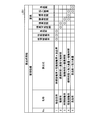
- FIG. 5 is a diagram showing an example of the work input record table definition 204A according to the embodiment
- FIG. 6 is a diagram showing an example of the operation history record table definition 205A according to the embodiment
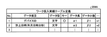
- FIG. 7 is a diagram showing an example of the state classification master table definition 206A according to the embodiment.
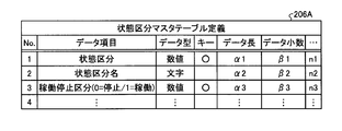
- FIG. 8 is a diagram showing an example of the standard time master table 203B according to the embodiment
- FIG. 9 is a diagram showing an example of the work input record table 204B according to the embodiment
- FIG. 10 is a diagram showing an example of the operation history record table 205B according to the embodiment
- FIG. 11 is a diagram showing an example of the working hour master table 207 according to the embodiment.
- the table stored in the database 10 is a master table 102 that stores data in which data is defined in advance such as standard time and status classification, and devices 41 to 41 such as work input records and equipment operation history. It is divided into a performance table 103 storing the performance data of 43.
- the standard time master table 203B and the working time master table 207 are the master table 102.
- the work input record table 204B and the operation history record table 205B are the record table 103.
- the standard time master table definition 203A of FIG. 4 shows the table definition of the standard time master table 203B that stores master data of standard time.
- the work input result table definition 204A the operation history result table definition 205A
- the status classification master table definition 206A "data type" of each data item, "key” existence, "data length”, “Data decimal point” etc. are specified.
- Examples of data items in the standard time master table definition 203A are a device ID (identification) for identifying a device used in each of the production facilities 310 to 330, and standard time.
- the standard time in the standard time master table definition 203A is defined in seconds, for example.
- the "data type” is a format of data, and the example of the “data type” is a character or a numerical value.
- the "key” is a primary key used when searching for data.
- the "data length” is the length of the data, and the “data decimal number” is the number of digits after the decimal point of the data.
- the work input record table definition 204A in FIG. 5 shows the table definition of the work input record table 204B that stores the element data of the input quantity.
- Examples of data items in the work input record table definition 204A are the device ID and the accounting date and time.
- the accounting date and time indicates the date and time when the result of the work input is accounted for.
- the accounting date and time in the work input record table definition 204A is defined by year, month, day, hour, minute, and second, for example.
- the operation history record table definition 205A in FIG. 6 shows the table definition of the operation history record table 205B that stores the element data of the operation time.
- Examples of data items in the operation history record table definition 205A are device ID, state classification, change start date and time, and change end date and time.
- the status division indicates the status of the production facilities 310 to 330
- the change start date/time indicates the date/time when the state division starts changing
- the change end date/time indicates the date/time when the state classification ends changing.
- Examples of the state classifications include a work being processed state, a work input waiting state, an abnormal state, and a power-off state.
- the change start date and time and the change end date and time in the operation history record table definition 205A are defined by year, month, day, hour, minute, and second, for example.
- State classification master table definition 206A in FIG. 7 shows the table definition of the table that stores the master data of the status classification.
- Examples of data items in the status classification master table definition 206A are status classification, status classification name, and operation stop classification.
- the status classification name is the name of the status classification
- the operation stop classification indicates the operation or stop of the production facilities 310 to 330. For example, when the production facilities 310 to 330 are stopped, the operation stop category is indicated by "0", and when the production equipment is in operation, the operation stop category is indicated by "1".
- the data processing according to the performance table definition such as the work input performance table definition 204A and the operation history performance table definition 205A corresponds to the generation of the element data in the uniform format.
- the standard time master table 203B of FIG. 8 is a table for storing element data of standard time.
- the element data in the standard time master table 203B is created based on the standard time master table definition 203A.
- the device ID and the standard time are associated with each other.
- the standard time in the standard time master table 203B is indicated in seconds according to the standard in the standard time master table definition 203A.
- the work input record table 204B in FIG. 9 is a table for storing element data of the input quantity.
- the element data in the work input record table 204B is created based on the work input record table definition 204A.
- the device ID is associated with the accounting date and time.
- the accounting date and time in the work input result table 204B is indicated by year, month, day, hour, minute, and second according to the rule in the work input result table definition 204A.
- the operation history record table 205B in FIG. 10 is a table that stores element data of operation time.
- the element data in the operation history record table 205B is created based on the operation history record table definition 205A.
- the status classification, change start date and time, and change end date and time are registered for each device ID.
- the change start date and time and the change end date and time in the operation history record table 205B are indicated by year, month, day, hour, minute, and second according to the rules in the operation history record table definition 205A.
- the working hour master table 207 of FIG. 11 is a table that stores element data of working hours.
- the element data in the working hour master table 207 is created based on the master table definition corresponding to the working hour master table 207.
- the working hour name, shift start date and time, shift end date and time, operable time, and planned downtime are registered for each working hour ID.
- the working hours ID is information for identifying the working hours
- the working hours name is the name of the working hours. Examples of working hours are day and night shifts.
- the shift start date and time is the date and time when the shift work was started, and the shift end date and time is the date and time when the shift work was ended.
- the planned downtime is a time during which the production facilities 310 to 330 are stopped according to the plan.
- the table storage unit 12 stores the master table corresponding to the status classification master table definition 206A. ..
- the description of the master table definition corresponding to the working hour master table 207 is omitted, but the table storage unit 12 stores the master table definition corresponding to the working hour master table 207. ..
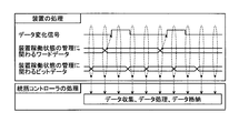
- FIG. 12 is a diagram for explaining a collection timing of facility data collected by the management index calculation system 1 according to the embodiment.
- FIG. 12 shows the processing of the devices 41 to 43 in the production facilities 310 to 330 and the processing of the general controller 20.
- the processing of the devices 41 to 43 there is shown a timing chart in which the devices 41 to 43 send the equipment data to the overall controller 20 via the equipment PLCs 31 to 33.
- the devices 41 to 43 detect that the equipment data they are handling has changed. Further, the devices 41 to 43 generate word data related to management of the device operating state, and generate bit data related to management of the device operating state. The devices 41 to 43 provide a data change signal indicating whether or not the data has changed, word data related to management of the device operating state, and bit data related to management of the device operating state at a specific timing. Send to.
- the general controller 20 collects equipment data sent from the devices 41 to 43, executes data processing that is data processing to generate element data, and stores the element data in the database 10.
- the data processing logic is defined by the sequence program, and the data format when collecting the equipment data from the production equipment 310 to 330 is defined by the allocation table of the storage area for storing the equipment data.
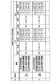
- FIG. 13 is a table showing a storage area assigned to the first equipment data sent from the equipment PLCs 31 to 33 according to the embodiment to the overall controller 20.
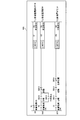
- FIG. 14 is a table showing a storage area assigned to the second equipment data sent from the equipment PLCs 31 to 33 according to the embodiment to the overall controller 20.
- FIG. 15 is a diagram showing an example of a sequence program 500 used when the general controller 20 according to the embodiment processes the equipment data.
- FIG. 13 and 14 show an allocation table of storage areas of facility data transmitted and received between the production facilities 310 to 330 and the general controller 20. Specifically, in FIG. 13, the addresses in the first allocation area of the memory device are shown as the allocation area of the equipment data for each device, and in FIG. 14, the addresses of the memory device are allocated as the allocation area of the equipment data for each device. Addresses in the second allocation area are shown. In FIG. 13, (1) indicates that it is within the first allocation area, and (2) indicates that it is within the second allocation area in FIG. 14. Therefore, (1) 000 to 0FF indicates the range of 000 to 0FF in the first allocation area, and (2) 000 to 0FF indicates the range of 000 to 0FF in the second allocation area.
- the data content of the equipment data, the range in the storage area for storing the equipment data, the number of points of the stored equipment data, etc. are set.
- the range within the storage area for storing equipment data is defined by the address of the storage area for storing equipment data. It can be said that the range within the storage area for storing the facility data defines the data amount of the facility data.
- the amount of equipment data corresponds to the number of digits of equipment data.
- the data content of the equipment data is the purpose of the equipment data and is indicated by the functions used in the devices 41 to 43. Collecting the facility data according to the allocation tables of FIGS. 13 and 14 corresponds to generating the facility data in a unified format.
- the allocation table of FIG. 13 is an allocation table for storing equipment data in bit data
- the allocation table of FIG. 14 is an allocation table for storing equipment data in word data. Bit data is represented by "0" or "1", and word data is represented by 16 bits.
- the sequence program 500 is a program used when generating element data for calculating the performance utilization rate by data processing.
- the equipment data used in the sequence program 500 is obtained from the equipments 41 to 43 in the production equipments 310 to 330 by the equipments PLCs 31 to 33, and is transmitted from the equipments PLCs 31 to 33 to the general controller 20 in the format shown in FIG. Sent.
- the facility data defined in FIG. 13 is sent to the overall controller 20 as bit data, and the facility data defined in FIG. 14 is sent to the overall controller 20 as word data.
- the equipment data sent from the equipment PLCs 31 to 33 to the overall controller 20 is equipment data of the functions of the devices 41 to 43.
- the facility data of each function includes facility data input to the function and facility data output from the function.
- the example of the equipment data input from the general controller 20 to the equipment PLCs 31 to 33 is the data of the time synchronization function
- the example of the equipment data sent from the equipment PLCs 31 to 33 to the general controller 20 is the data of the input result collection function, the quality information. It is the data of the collection function.
- the time synchronization function is a function of synchronizing the internal clocks of the devices 41 to 43 and the internal clock of the general controller 20.
- the input result collection function is a function of collecting the result information of the works input to the devices 41 to 43.
- the quality information collecting function is a function of collecting quality information of the works processed by the devices 41 to 43.
- the allocation table of FIG. 13 includes a bit data storage address for storing equipment data required for the sequence program 500.
- the equipment data necessary for the sequence program 500 is equipment data related to the operation preparation of the A1 device and the A2 device, the system lock, and the like.
- the bit data storage address of the equipment data related to the A1 device operation preparation, system lock, etc. is (1) 010 to 01F assigned to the equipment data of the operating state management function, and the A2 device operation preparation, system lock, etc.
- the bit data storage addresses of the equipment data related to (1) are 110 to 11F assigned to the equipment data of the operating state management function.
- the A1 device and the A2 device are any of the devices 41 to 43, respectively.
- the allocation table of FIG. 14 includes a device ID storage address (not shown) that stores a device ID for identifying the devices 41 to 43.
- the points of the address where the facility data is registered and the range of the address where the facility data is registered are set for the devices 41 to 43. Further, for each function, the score of the address where the facility data is registered and the range of the address where the facility data is registered are set. For example, 16 addresses are set for each facility data input to each function of the A1 device, and 256 addresses are set for each facility data input for all functions of the A1 device. In this way, in the management index calculation system 1, the allocation position of the equipment data to each function is set.
- the devices 41 to 43 send the equipment data in the uniform format shown in FIGS. 13 and 14 to the overall controller 20 via the equipment PLCs 31 to 33.
- the user of the management index calculation system 1 defines a uniform format for the facility data of each function shown in FIG. 13 or 14 so that the management index calculation system 1 calculates the management index.
- This unified format is set in the devices 41 to 43.
- the devices 41 to 43 can send the equipment data in the set uniform format to the overall controller 20, and the overall controller 20 collects the equipment data from each of the devices 41 to 43 in the same data format. be able to.
- FIG. 16 is a diagram showing the content information of the facility data collected by the general controller 20 according to the embodiment.
- FIG. 16 shows the correspondence between the address in the second allocation area shown in FIG. 14 and the contents of the equipment data registered at this address.
- the devices 41 to 43 send the facility data to the overall controller 20 according to the correspondence relationship shown in FIG.
- Addresses 830 to 835 shown in FIG. 16 are all areas in which facility data of the quality information collecting function is stored. For example, at the address 830 in the second area, the determination result flag corresponding to the characteristic 1 of the quality information collecting function is stored. The determination result flag indicates the result of determination made on the characteristic 1 related to the quality information collecting function.
- the collected data items such as the judgment result flag, the number of continuous tests, and the result value which is a characteristic value are patterned. Further, in the present embodiment, data items are collected in the same pattern for each quality characteristic.
- the number of continuous tests is the number of continuous tests in the quality test.
- the characteristic value is the result of the quality test and indicates the characteristic of the work as a product.
- the facility data allocation table may be provided with a device-specific storage area for storing data that is not related to management indexes and that is desired to be collected by the device. Since the user can set the device-specific data type, storage address, storage data amount, and data content in the device-specific storage area, the overall controller 20 collects data unique to each device. It becomes possible to do.
- the device-specific storage area is used, by registering the setting contents in the master table 102, the device-specific data collected in the database 10 can be easily confirmed after collection.
- the equipment data of functions such as the quality information collection function or the device-specific data may differ in the amount of data to be acquired for each device.
- the allocation area of the function not used by the device may be deleted, and a part or all of the deleted allocation area may be used as the allocation area of the function that is uniquely used by the device. That is, it is possible to increase or decrease the allocation area of each function in each device.
- the allocation area of the function not used in any of the devices may be deleted, and a part or all of the deleted allocation area may be used as the allocation area of the other device. As a result, the allocation area of each device can be increased or decreased.
- the allocation area of each device can be increased or decreased.
- the overall controller 20 executes the sequence program 500 according to the data allocation table shown in FIGS. 13 and 14.
- the line indicated by (0) in the sequence program 500 is the case where the power supply of the device is OFF. Further, the line indicated by (60) in the sequence program 500 is the case where the device is in the adjustment, and the line indicated by (67) in the sequence program 500 is the case when the device is processing the work.
- the location of “MOV K1 D0” in the sequence program 500 is the process of writing “1” in decimal notation to the area of D0 where the status classification is stored. Therefore, when the power of the device is OFF, "1" is written as the status classification.
- the portion of “MOV K2 D0” in the sequence program 500 is a process of writing “2” in decimal notation to the area of D0 in which the status classification is stored. Therefore, when the device is under adjustment, "2” is written as the status classification.
- the portion of “MOV K3 D0” in the sequence program 500 is a process of writing “3” in decimal to the area of D0 in which the status classification is stored. Therefore, when the device is processing a workpiece, "3" is written as the status classification.
- FIG. 17 is a diagram for explaining an operation processing procedure of the management index calculation system 1 according to the embodiment.
- the master table 102 is input in advance to the database 10 by the user (step ST100).
- the equipment PLCs 31 to 33 operate according to their sequence programs. That is, the equipment PLCs 31 to 33 control the devices 41 to 43 based on the respective sequence programs.
- the equipment data required to calculate the management index is acquired by each of the devices 41 to 43 as equipment data in a unified format in the form of an allocation table as shown in FIG. 13 or FIG. 14 (step ST1).
- the equipment data acquired by each of the devices 41 to 43 is transmitted to the overall controller 20 by the equipment PLCs 31 to 33 according to the data transmission timing chart shown in FIG. 12 (step ST2).
- the equipment PLC 31 transmits the equipment data acquired by the device 41 to the overall controller 20
- the equipment PLC 32 transmits the equipment data acquired by the device 42 to the overall controller 20
- the equipment PLC 33 transmits the equipment data.
- the facility data acquired in 43 is transmitted to the overall controller 20.
- the equipment PLCs 31 to 33 transmit the equipment data of their own equipment to the overall controller 20 based on the allocation table in the unified format and the timing chart of FIG. 12, regardless of the management index request from the user.
- the timing chart used by the equipment PLCs 31 to 33 may be a timing chart in which the production equipments 310 to 330 collect data in response to a data request from the general controller 20.
- the general controller 20 receives the facility data for each production facility from the production facilities 310 to 330 (step ST3).
- the overall controller 20 extracts the equipment data necessary for provision to the database 10 from the equipment data in the uniform format collected from each of the production equipment 310 to 330 based on the sequence program 500 shown in FIG.
- the overall controller 20 performs data processing in accordance with the table definition of the performance table 103 of the database 10 (step ST4), and sends it to each performance table 103 of the database 10 as element data (step ST5). That is, the overall controller 20 makes the element data in a form according to the data item, the data format, and the number of digits defined by the table definition of the performance table 103 that stores the element data for the database 10 to calculate the management index. Data processing is performed on the equipment data, and the data is transmitted to the performance table 103 of the database 10.
- the database 10 receives the element data for each production facility from the overall controller 20 (step ST6) and stores the element data in the area in the performance table 103 corresponding to the element data.
- the equipment PLCs 31 to 33 use the device ID data, which is the individual identification management number of its own device, as the device ID storage address of the allocation table described in FIG. Store in the indicated area. Further, the equipment PLCs 31 to 33 transmit the equipment data for operation preparation necessary for the sequence program 500 and the equipment data in bits such as the number of seconds of system lock to the area indicated by the bit data storage address of the allocation table described in FIG. Store.
- the overall controller 20 uses the sequence program 500 to determine the status classification of each production facility 310 to 330 from the facility data stored by each production facility 310 to 330.
- the overall controller 20 stores the device ID, the number indicating the state classification, the change start date and time, the change end date and time, and other necessary data stored from each of the production facilities 310 to 330, at the time when the state classification has changed. Are collectively stored in the operation history record table 205B of the database 10.
- the central controller 20 collects data from a plurality of production facilities 310 to 330 simultaneously in parallel, the plurality of production facilities may be one management unit. That is, the overall controller 20 may generate element data for each of a plurality of production facilities from the facility data collected from the production facilities 310 to 330 and store the element data in the database 10. For example, the overall controller 20 regards the process of three A1 devices, A2 devices, and A3 devices arranged in different production facilities of the same type as the A process, and the three processes of the A1 device, A2 device, and A3 device. When the equipment status classification is in operation, the process A may be in operation.
- the general controller 20 by setting a new sequence program with a plurality of production facilities as one management unit, the general controller 20 generates the facility data of the state classification of the process A, and the respective production facilities 310 to 330.
- the operation history record table 205B can be stored in the same manner as the operation history of the above.
- the user operates the web application or the exe application from the information processing terminal to obtain information on the management index of the production equipment 310 to 330 in the daily management work of the production equipment 310 to 330, and requests the management index,
- the production index corresponding to the management index and the period of the management index are designated, and the management index is requested to the database 10 (step ST101).
- the combining unit 13 extracts the element data necessary for calculating the management index of the requested production equipment and period from the performance table 103 (step ST7). .. Then, the combining unit 13 of the database 10 combines the master data of the master table 102 previously input by the user with the element data (step ST8). Specifically, the combining unit 13 converts the code of the element data into data according to the master data of the master table 102. The combining unit 13 enables the content of the element data to be specified by associating the content of the element data with the content defined in the master table 102. As a result, the data in the list can be confirmed by the user as to the content of the element data indicated by the code.
- the calculation unit 14 calculates the management index requested by the user based on the combined data (step ST9).
- the output unit 15 outputs the calculated value of the management index to the web application or the exe application of the information processing terminal operated by the user (step ST10). As a result, the management index designated by the user is displayed on the monitor or the like of the information processing terminal.
- the connection unit 13 of the database 10 extracts the element data used for calculating the equipment operating time of the device 41 from the operation history record table 205B based on the operation history record table definition 205A.
- the device ID is “1”
- the equipment state classification is “1” indicating that the operation is in progress
- the change end date and time is after Jan. 10, 2018 8:00 and the change start date and time is 2018.
- the element data before 17:00 on January 10, 2010 is extracted.
- the combining unit 13 may extract element data whose operation stop classification is "1" indicating that the operation stop is in operation.
- the calculating unit 14 uses the element data extracted by the combining unit 13 to set the device ID to “1”, the equipment state classification to “1” indicating that the device is in operation, and the change end date and time is January 2018. After 8:00 on the 10th, the total sum of the times of the element data whose change start date and time is before 17:00 on January 10, 2018 is calculated.
- the coupling unit 13 extracts the element data for calculating the quantity input to the device 41 from the work input result table 204B based on the work input result table definition 204A, and the calculation unit 14 based on the extraction result. Then, the quantity input to the device 41 is calculated.
- the combining unit 13 here extracts the element data whose device ID is “1” and whose work accounting date is from 8:00 to 17:00 on January 10, 2018, and displays the number of extracted data items.
- the calculation unit 14 totals. Since one work accounting date and time is registered each time one work is input, the number of data items and the input amount are equal. Therefore, the calculation unit 14 handles the total number of data cases as the input quantity.
- the combining unit 13 extracts the master data of the standard time of the device 41 from the standard time master table 203B based on the standard time master table definition 203A.
- the combining unit 13 here extracts the standard time with the device ID “1”.
- the calculation unit 14 calculates the performance operation rate according to the KPI calculation formula using the standard time, the operation time, and the input quantity. Specifically, the calculation unit 14 calculates the performance operation rate by dividing the product of the standard time and the input quantity by the operation time.
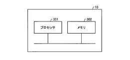
- FIG. 18 is a diagram illustrating a hardware configuration example of the database 10 according to the embodiment.
- the database 10 can be realized by the processor 301 and the memory 302 shown in FIG.
- the processor 301 are a CPU (Central Processing Unit, a central processing unit, a processing unit, an arithmetic unit, a microprocessor, a microcomputer, a processor, also called a DSP (Digital Signal Processor)) or a system LSI (Large Scale Integration).
- Examples of the memory 302 are RAM (Random Access Memory) and ROM (Read Only Memory).
- the database 10 is realized by the processor 301 reading and executing a database application program for executing the operation of the database 10 stored in the memory 302. It can also be said that this database application program causes a computer to execute the procedure or method of the database 10.
- the memory 302 is also used as a temporary memory when the processor 301 executes various processes.
- the functions of the database 10 may be partially realized by dedicated hardware and partially realized by software or firmware. Further, the general controller 20 and the equipment PLCs 31 to 33 may be realized by the processor 301 and the memory 302 shown in FIG.
- the general controller 20 receives various pieces of equipment data in a uniform format from each of the production equipment 310 having the equipment PLC 31, the production equipment 320 having the equipment PLC 32, and the production equipment 330 having the equipment PLC 33. To collect.
- the management index calculation system 1 uses a single data processing logic to convert the collected equipment data into a data format according to the master table 102, and stores it as element data of the performance table 103.
- the overall controller 20 since the plurality of production equipments 310 to 330 transmit the equipment data in the uniform format to the overall controller 20, the overall controller 20 has the unified format sent from each of the production equipments 310 to 330.
- the equipment data may be processed by a single data processing logic and stored in the database 10 as element data.
- the database 10 may calculate the management index by a single calculation logic for each management index based on the element data stored by the overall controller 20 and unified regardless of the types of the production facilities 310 to 330. ..
- the burden of data processing and management index calculation is suppressed, and one management index calculation system 1 can easily calculate the management indexes of many different types of production equipment.
- the management index calculation system 1 uses the unified data format to unify the data storage area, data format, and number of digits for the data items required to calculate the management index.
- the management index calculation system 1 has a fixed data storage area and data pattern for quality data having different items for each production facility, and the number of data items, the data format, and the number of digits are variable.
- the management index calculation system 1 provides a data area in which the data pattern, the data format, the number of digits, etc. can be freely set in the data format for the data items that are acquired for each production equipment and differ for each production equipment. ..
- the overall controller 20 can combine various equipment data of the production equipments 310 to 330 to be managed by collecting various equipment data from the production equipments 310 to 330 in real time and processing the data.
- the general controller 20 can easily generate element data of a process or line in units of a plurality of production facilities and store it in the database 10.
- the database 10 does not need to generate element data in units of a plurality of production facilities from stored history data for each production facility, and manages the data based on the stored element data in units of a plurality of production facilities.
- the management index can be calculated by the index calculation logic. Therefore, the processing load on the database 10 is suppressed, and the management index can be efficiently calculated and output. Further, by separating the facility data storage function and management function, which are the original functions of the database 10, from the management index calculation function, the management index calculation system 1 can be easily constructed.
- the general controller 20 collects the facility data generated from the production facilities 310 to 330 in the unified data format, and uses the single data processing logic to calculate the facility data. Converted to element data to be used. Further, the database 10 stores the element data from the general controller 20 in the data storage area in a unified data format, and manages the element data in the data storage area with a single calculation logic for each management index. The index is calculated. As a result, the management index calculation system 1 can easily collect the facility data and easily acquire the element data, and thus can easily calculate the management index.
- 1 management index calculation system 1 display monitor, 10 database, 12 table storage section, 13 combination section, 14 calculation section, 15 output section, 20 integrated controller, 21 communication section, 22 data processing section, 31-33 equipment PLC, 41 ⁇ 43 device, 102 master table, 103 result table, 201 calculation formula information, 202 element information, 203A standard time master table definition, 203B standard time master table, 204A work input result table definition, 204B work input result table, 205A operation history Actual table definition, 205B operation history actual table, 206A status classification master table definition, 207 working hour master table, 310-330 production equipment, 500 sequence program.
Landscapes
- Engineering & Computer Science (AREA)
- Physics & Mathematics (AREA)
- General Physics & Mathematics (AREA)
- Automation & Control Theory (AREA)
- General Engineering & Computer Science (AREA)
- Manufacturing & Machinery (AREA)
- Quality & Reliability (AREA)
- General Factory Administration (AREA)
- Testing And Monitoring For Control Systems (AREA)
Abstract
This management index calculation system (1) comprises: a plurality of production facilities (310 to 330) that comprise a device and a control device for controlling the device; a general controller (20) that collects from each of the plurality of production facilities (310 to 330) facility data that is data of the production facilities (310 to 330), and that is generated in a first data format unified between the plurality of production facilities (310 to 330), and so as to become a second data format unified between the plurality of production facilities (310 to 330), converts the facility data of the first data format using a processing logic common to each of the facility data collected from the plurality of production facilities (310 to 330) to element data used for calculation of the management index of the plurality of production facilities (310 to 330); and a database (10) that stores the element data of the second data format in a data storage region, and calculates the management index with the calculation logic of each management index using the element data inside the data storage region.
Description
本発明は、管理指標を算出する管理指標算出システムおよび管理指標算出方法に関する。
The present invention relates to a management index calculation system and a management index calculation method for calculating a management index.
自動化された生産設備から種々のデータを収集し、収集したデータを用いて生産設備の管理指標を算出するシステムがある。特許文献1に記載のサービス情報提供システムでは、生産設備毎に配置されたデータ収集装置が、データ収集方法が定義された定義ファイルに基づいて、生産設備からデータを収集し、収集したデータから生産設備の状態変化などを示すイベントデータを生成してリモートセンタ装置に供給し、リモートセンタ装置が分析処理などを行っている。この特許文献1に記載のサービス情報提供システムは、各データ収集装置が生産設備から収集する設定項目の数を同じにすることで、各データ収集装置がリモートセンタ装置に出力するデータパケットの形式を統一している。
There is a system that collects various data from automated production equipment and uses the collected data to calculate the production equipment management index. In the service information providing system described in Patent Document 1, a data collection device arranged for each production facility collects data from the production facility based on a definition file in which a data collection method is defined, and produces from the collected data. Event data indicating a change in the state of equipment is generated and supplied to a remote center device, and the remote center device performs analysis processing and the like. In the service information providing system described in Patent Document 1, the number of setting items collected from the production equipment by each data collecting device is the same, so that the format of the data packet output by each data collecting device to the remote center device is determined. It is unified.
しかしながら、上記特許文献1の技術では、上下水道施設を監視および制御する監視制御システムが蓄積するデータの種類または形式が異なる場合には、データ収集装置毎に別々の定義ファイルを設定すること、および収集したデータからイベントデータを生成するための変換処理を監視制御システム毎に設定することが必要であった。このため、上記特許文献1の技術では、複数の生産設備に対して管理指標を容易に算出することができなかった。
However, in the technique of Patent Document 1 described above, if the type or format of the data accumulated by the supervisory control system that monitors and controls the water and sewage facilities is different, a separate definition file is set for each data collection device, and It was necessary to set a conversion process for generating event data from the collected data for each supervisory control system. Therefore, the technique of Patent Document 1 cannot easily calculate the management index for a plurality of production facilities.
本発明は、上記に鑑みてなされたものであって、複数の生産設備に対して管理指標を容易に算出することができる管理指標算出システムを得ることを目的とする。
The present invention has been made in view of the above, and an object thereof is to obtain a management index calculation system that can easily calculate a management index for a plurality of production facilities.
上述した課題を解決し、目的を達成するために、本発明の管理指標算出システムは、装置および装置を制御する制御装置を備えた複数の生産設備を備える。また、管理指標算出システムは、複数の生産設備のそれぞれから生産設備のデータであって複数の生産設備間で統一された第1のデータフォーマットで生成された設備データを収集し、複数の生産設備の管理指標の算出に用いる要素データが複数の生産設備間で統一された第2のデータフォーマットとなるよう、複数の生産設備から収集した設備データのそれぞれに共通の処理ロジックで第1のデータフォーマットの設備データを要素データに変換する統括制御装置を備える。また、管理指標算出システムは、第2のデータフォーマットの要素データをデータ格納領域に格納し、データ格納領域内の要素データを用いて管理指標毎の算出ロジックで管理指標を算出するデータベースを備える。
In order to solve the above-mentioned problems and achieve the purpose, the management index calculation system of the present invention includes a plurality of production facilities including a device and a control device for controlling the device. In addition, the management index calculation system collects the equipment data generated from each of the plurality of production equipment in the first data format that is unified among the plurality of production equipment to generate the plurality of production equipment. The first data format with the processing logic common to each of the equipment data collected from the plurality of production equipments so that the element data used for the calculation of the management index of the equipments has the second data format unified among the plurality of production equipments. The integrated control device for converting the equipment data of 1 to the element data is provided. Further, the management index calculation system includes a database that stores the element data of the second data format in the data storage area and calculates the management index by the calculation logic for each management index using the element data in the data storage area.
本発明にかかる管理指標算出システムは、複数の生産設備に対して管理指標を容易に算出することができるという効果を奏する。
The management index calculation system according to the present invention has an effect that the management index can be easily calculated for a plurality of production facilities.
以下に、本発明の実施の形態にかかる管理指標算出システムおよび管理指標算出方法を図面に基づいて詳細に説明する。なお、この実施の形態によりこの発明が限定されるものではない。
The management index calculation system and the management index calculation method according to the embodiment of the present invention will be described below in detail with reference to the drawings. The present invention is not limited to this embodiment.
実施の形態.
図1は、実施の形態にかかる管理指標算出システム1の構成を示す図である。管理指標算出システム1は、生産設備310~330といった設備の管理指標を算出するシステムである。管理指標算出システム1は、生産設備310~330と、統括コントローラ20と、データベース10とを備えている。管理指標算出システム1では、統括コントローラ20が、データベース10および生産設備310~330に接続されている。また、データベース10は、液晶モニタといった表示モニタ2に接続されている。なお、以下の説明では、生産設備310~330を識別する必要がない場合には、生産設備310~330を生産設備という場合がある。 Embodiment.
FIG. 1 is a diagram showing a configuration of a managementindex calculation system 1 according to an embodiment. The management index calculation system 1 is a system that calculates a management index of equipment such as production equipment 310 to 330. The management index calculation system 1 includes production facilities 310 to 330, a general controller 20, and a database 10. In the management index calculation system 1, the general controller 20 is connected to the database 10 and the production facilities 310 to 330. The database 10 is also connected to a display monitor 2 such as a liquid crystal monitor. In the following description, the production facilities 310 to 330 may be referred to as the production facilities when it is not necessary to identify the production facilities 310 to 330.
図1は、実施の形態にかかる管理指標算出システム1の構成を示す図である。管理指標算出システム1は、生産設備310~330といった設備の管理指標を算出するシステムである。管理指標算出システム1は、生産設備310~330と、統括コントローラ20と、データベース10とを備えている。管理指標算出システム1では、統括コントローラ20が、データベース10および生産設備310~330に接続されている。また、データベース10は、液晶モニタといった表示モニタ2に接続されている。なお、以下の説明では、生産設備310~330を識別する必要がない場合には、生産設備310~330を生産設備という場合がある。 Embodiment.
FIG. 1 is a diagram showing a configuration of a management
本実施の形態の管理指標算出システム1では、統括コントローラ20が、生産設備310~330のデータである設備データを統一された第1のデータフォーマットで生産設備310~330から収集し、単一のデータ処理ロジックで、設備データを生産設備310~330の管理指標の算出に用いる第2のデータフォーマットの要素データに変換する。管理指標算出システム1では、生産設備310~330から収集した設備データのデータフォーマットが統一されているので、単一の処理ロジックで要素データに変換することが可能である。統括コントローラ20は、統一された第2のデータフォーマットの要素データをデータベース10に送信してデータベース10に格納させる。すなわち、統括コントローラ20からデータベース10へ送られる要素データは、データベース10に送信される際のデータパケットの形式ではなく、データフォーマット自体が統一されている。データベース10は、統一された第2のデータフォーマットで要素データを格納しておき、前記管理指標毎に単一の算出ロジックで要素データを用いて管理指標を算出する。管理指標算出システム1では、管理指標に必要な要素データは、予め定められたデータフォーマットで格納されているので、算出ロジックの組立てが容易である。なお、以下の説明では、統一されたデータフォーマットを統一フォーマットという場合がある。
In the management index calculation system 1 according to the present embodiment, the overall controller 20 collects equipment data, which is data of the production equipments 310 to 330, from the production equipments 310 to 330 in the unified first data format, and collects the single data. The data processing logic converts the equipment data into element data of the second data format used for calculating the management index of the production equipments 310 to 330. In the management index calculation system 1, since the data formats of the equipment data collected from the production equipments 310 to 330 are unified, it is possible to convert into the element data with a single processing logic. The overall controller 20 transmits the element data in the unified second data format to the database 10 and stores the element data in the database 10. That is, the element data sent from the overall controller 20 to the database 10 has a unified data format, not the format of the data packet when sent to the database 10. The database 10 stores the element data in a unified second data format, and calculates the management index using the element data with a single calculation logic for each management index. In the management index calculation system 1, the element data required for the management index is stored in a predetermined data format, so that the calculation logic can be easily assembled. In the following description, the unified data format may be referred to as a unified format.
生産設備310は、設備PLC(プログラマブルロジックコントローラ:Programmable Logic Controller)31と、設備PLC31に制御される装置41とを備えている。同様に、生産設備320は、設備PLC32と、設備PLC32に制御される装置42とを備えており、生産設備330は、設備PLC33と、設備PLC33に制御される装置43とを備えている。なお、以下の説明では、装置41~43を識別する必要がない場合には、装置41~43を装置という場合がある。
The production facility 310 includes a facility PLC (Programmable Logic Controller) 31 and a device 41 controlled by the facility PLC 31. Similarly, the production facility 320 includes a facility PLC 32 and a device 42 controlled by the facility PLC 32, and the production facility 330 includes a facility PLC 33 and a device 43 controlled by the facility PLC 33. In the following description, the devices 41 to 43 may be referred to as devices when it is not necessary to identify the devices 41 to 43.
設備PLC31~33は、自動化生産を行う生産設備310~330に配置される制御機器の一例である。設備PLC31~33は、生産設備310~330に配置されている被制御機器である装置41~43の動作を制御する。被制御機器の例は、ロボットである。
The equipment PLCs 31 to 33 are examples of control devices arranged in the production equipments 310 to 330 that perform automated production. The equipment PLCs 31 to 33 control the operations of the devices 41 to 43 which are the controlled equipments arranged in the production equipments 310 to 330. An example of the controlled device is a robot.
設備PLC31~33は、種々のデータを用いてそれぞれに接続されている装置41~43を制御するとともに、装置41~43の状態を示すデータを保持している。設備PLC31~33は、統括コントローラ20から要求のあった設備データを統括コントローラ20に送る。すなわち、設備PLC31が、装置41で取得された設備データを統括コントローラ20に送信し、設備PLC32が、装置42で取得された設備データを統括コントローラ20に送信し、設備PLC33が、装置43で取得された設備データを統括コントローラ20に送信する。なお、管理指標算出システム1が備える設備PLCは、設備PLC31~33の3つに限らず、2つであってもよいし4つ以上であってもよい。また、各設備PLC31~33は、複数の装置を制御してもよい。
The equipment PLCs 31 to 33 use various data to control the devices 41 to 43 connected thereto, and hold data indicating the states of the devices 41 to 43. The equipment PLCs 31 to 33 send the equipment data requested by the general controller 20 to the general controller 20. That is, the equipment PLC 31 transmits the equipment data acquired by the device 41 to the general controller 20, the equipment PLC 32 transmits the equipment data acquired by the device 42 to the general controller 20, and the equipment PLC 33 acquires the equipment 43. The generated facility data is transmitted to the general controller 20. Note that the equipment PLCs included in the management index calculation system 1 are not limited to the three equipments PLCs 31 to 33, and may be two or four or more. Further, each of the equipment PLCs 31 to 33 may control a plurality of devices.
統括コントローラ20は、設備PLC31~33から設備データを収集する。統括コントローラ20は、設備PLC31~33から統一フォーマットの種々の設備データを収集し、設備データを特定の形式に変換する。統括コントローラ20は、通信部21と、データ処理部22とを備えている。
The general controller 20 collects equipment data from the equipment PLCs 31 to 33. The overall controller 20 collects various equipment data in a uniform format from the equipment PLCs 31 to 33 and converts the equipment data into a specific format. The overall controller 20 includes a communication unit 21 and a data processing unit 22.
通信部21は、設備PLC31~33との間でデータ通信を行なう。また、通信部21は、データベース10との間でデータ通信を行なう。通信部21は、設備PLC31~33から設備データを受信し、データ処理部22でデータ処理された後のデータである後述の要素データをデータベース10に送信する。
The communication unit 21 performs data communication with the equipment PLCs 31 to 33. The communication unit 21 also performs data communication with the database 10. The communication unit 21 receives the equipment data from the equipment PLCs 31 to 33, and transmits element data, which will be described later, which is the data after being data-processed by the data processing unit 22, to the database 10.
データ処理部22は、設備PLC31~33から送られてきた設備データを、データベース10にて特定の形式で格納できるようデータ処理し、データ処理後のデータを要素データとして実績テーブル103に格納する。実績テーブル103については後述する。
The data processing unit 22 performs data processing on the equipment data sent from the equipment PLCs 31 to 33 so that it can be stored in the database 10 in a specific format, and stores the data after the data processing in the result table 103 as element data. The performance table 103 will be described later.
データベース10は、統括コントローラ20からの要素データを、統括コントローラ20から受け取って格納しておく。データベース10は、要素データと、事前に登録されているマスタデータと、を用いて、装置41~43が配置されている生産設備310~330の管理指標を算出する。データベース10は、マスタテーブル102のテーブル定義および実績テーブル103のテーブル定義に基づいて、収集された要素データを一覧表にし、管理指標を算出するための管理指標算出ロジックに従って一覧表から管理指標を算出する。テーブル定義は、テーブル記憶部12にマスタテーブル102および実績テーブル103を格納する際のフォーマットを定めたものである。マスタテーブル102については後述する。
The database 10 receives the element data from the general controller 20 from the general controller 20 and stores it. The database 10 calculates the management index of the production facilities 310 to 330 in which the devices 41 to 43 are arranged, using the element data and the master data registered in advance. The database 10 lists the collected element data based on the table definition of the master table 102 and the table definition of the actual result table 103, and calculates the management index from the list according to the management index calculation logic for calculating the management index. To do. The table definition defines the format for storing the master table 102 and the result table 103 in the table storage unit 12. The master table 102 will be described later.
データベース10は、算出した管理指標を外部装置に出力する。ここでのデータベース10は、管理指標を表示モニタ2に出力して表示モニタ2に管理指標を表示させる。また、データベース10は、算出した管理指標を、図示しない情報処理端末に出力してもよい。情報処理端末の例は、管理指標を管理するコンピュータである。
The database 10 outputs the calculated management index to an external device. The database 10 here outputs the management index to the display monitor 2 and causes the display monitor 2 to display the management index. Further, the database 10 may output the calculated management index to an information processing terminal (not shown). An example of the information processing terminal is a computer that manages a management index.
データベース10は、テーブル記憶部12と、結合部13と、算出部14と、出力部15とを備えている。結合部13、算出部14、および出力部15による各処理は、データベースアプリケーションプログラムによって実行される。換言すると、データベースアプリケーションプログラムは、データベース10の動作を実行するアプリケーションプログラムである。
The database 10 includes a table storage unit 12, a connection unit 13, a calculation unit 14, and an output unit 15. Each processing by the combination unit 13, the calculation unit 14, and the output unit 15 is executed by the database application program. In other words, the database application program is an application program that executes the operation of the database 10.
テーブル記憶部12は、マスタテーブル102および実績テーブル103を記憶する。マスタテーブル102は、収集する要素データの形式などを定義したテーブルであり、予めテーブル記憶部12に格納しておく。また、テーブル記憶部12は、マスタテーブル102および実績テーブル103のテーブル定義を格納しておく。実績テーブル103は、統括コントローラ20から送られてきた要素データを格納するテーブルである。設備データは、実績テーブル103のテーブル定義に沿ってデータ処理されることにより、要素データに変換される。この要素データが、実績テーブル103に格納される。したがって、実績テーブル103は、実績テーブル103のテーブル定義に沿って生成された要素データを格納するテーブルである。また、マスタテーブル102のテーブル定義は、要素データのコードをユーザに認識可能な一覧表に変換する際にも用いられる。
The table storage unit 12 stores a master table 102 and a performance table 103. The master table 102 is a table that defines the format of element data to be collected, and is stored in the table storage unit 12 in advance. The table storage unit 12 also stores the table definitions of the master table 102 and the performance table 103. The performance table 103 is a table that stores the element data sent from the overall controller 20. The equipment data is converted into element data by data processing according to the table definition of the performance table 103. This element data is stored in the performance table 103. Therefore, the performance table 103 is a table that stores the element data generated according to the table definition of the performance table 103. The table definition of the master table 102 is also used when converting the code of the element data into a list recognizable to the user.
結合部13は、ユーザに要求された管理指標を算出するために必要な要素データを、統括コントローラ20から送られてきた要素データの中から抽出する。また、結合部13は、ユーザに要求された管理指標を算出するために必要なマスタデータを、マスタテーブル102から抽出する。
The combining unit 13 extracts the element data necessary for calculating the management index requested by the user from the element data sent from the overall controller 20. Further, the combining unit 13 extracts from the master table 102 the master data necessary for calculating the management index requested by the user.
結合部13は、マスタテーブル102のマスタデータと、抽出した要素データとを結合する。結合部13がマスタテーブル102のマスタデータと要素データとを結合することによって、要素データの内容を、マスタテーブル102で定義された要素データのコードに対応付けする。これにより、要素データの内容が特定される。
The combining unit 13 combines the master data of the master table 102 and the extracted element data. By combining the master data of the master table 102 and the element data, the combining unit 13 associates the content of the element data with the code of the element data defined in the master table 102. Thereby, the content of the element data is specified.
算出部14は、結合部13で結合されたデータに基づいて、ユーザから要求のあった管理指標を算出する。管理指標の算出処理については後述する。出力部15は、算出部14が算出した管理指標を表示モニタ2などの外部装置に出力する。なお、算出部14および出力部15は、データベース10の外部に配置されていてもよい。
The calculating unit 14 calculates the management index requested by the user based on the data combined by the combining unit 13. The management index calculation process will be described later. The output unit 15 outputs the management index calculated by the calculation unit 14 to an external device such as the display monitor 2. The calculation unit 14 and the output unit 15 may be arranged outside the database 10.
データベース10は、ユーザが操作した情報処理端末のウェブ(web)アプリケーションまたはエグゼ(exe)アプリケーションから、管理指標の要求を受付けることが可能となっている。また、データベース10は、要求のあった管理指標を算出すると、要求を受付けたwebアプリケーションまたはexeアプリケーションに管理指標を出力することが可能となっている。したがって、表示モニタ2は、ユーザの情報処理端末が備えるものであってもよい。
The database 10 can accept a request for a management index from a web application or an exe application of an information processing terminal operated by a user. Further, when the database 10 calculates the requested management index, it can output the management index to the web application or the exe application that has received the request. Therefore, the display monitor 2 may be included in the information processing terminal of the user.
ここで、管理指標の詳細について説明する。管理指標は、組織の目標達成の度合いを定義する補助となる計量基準群である。管理指標は、組織の特性または戦略によって異なり、ISO(International Organization for Standardization:国際標準化機構)22400は、MES(Manufacturing Execution System:製造実行システム)領域でのKPI(Key Performance Indicator:重要業績評価指標)と、KPIを構成するデータの国際標準である。ISO22400では、生産性、品質、能力、環境、在庫、保全の6つの領域のKPIが定義されている。管理指標算出システム1は、生産設備毎に管理指標を算出する。
Here, the details of the management index will be explained. Management indicators are a set of measurement criteria that help define the degree to which an organization achieves its goals. The management index differs depending on the characteristics or strategy of the organization, and ISO (International Organization for Standardization) 22400 is a KPI (Key Performance Indicator) in the MES (Manufacturing Execution System) area. And is an international standard for data constituting KPI. ISO22400 defines KPIs in six areas: productivity, quality, capacity, environment, inventory, and maintenance. The management index calculation system 1 calculates a management index for each production facility.
図2は、実施の形態にかかる管理指標算出システム1で用いる算出式情報201の例を示す図である。図3は、実施の形態にかかる管理指標算出システム1で用いる要素情報202を示す図である。図3の要素情報202は、図2に示した要素の定義を示している。要素情報202は、要素の名称と、要素の定義との対応関係を示している。算出式情報201は、要素情報202に基づいて作成される。
FIG. 2 is a diagram showing an example of the calculation formula information 201 used in the management index calculation system 1 according to the embodiment. FIG. 3 is a diagram showing the element information 202 used in the management index calculation system 1 according to the embodiment. The element information 202 of FIG. 3 indicates the definition of the element shown in FIG. The element information 202 indicates the correspondence between the element name and the element definition. The calculation formula information 201 is created based on the element information 202.
算出式情報201は、算出部14が各生産設備の管理指標を算出する際に用いる算出式の情報である。算出式情報201は、生産設備における生産性領域のKPIである、総合効率、操業率、時間稼働率、性能稼働率、および良品率についての算出式と、これらの算出式を構成する要素との関係を示している。総合効率は生産設備の総合効率であり、操業率は生産設備の操業率である。
The calculation formula information 201 is information on a calculation formula used when the calculation unit 14 calculates the management index of each production facility. The calculation formula information 201 is a KPI of the productivity area in the production facility, which is a calculation formula for the total efficiency, the operating rate, the time utilization rate, the performance utilization rate, and the non-defective rate, and the elements constituting these calculation equations. Shows the relationship. The total efficiency is the total efficiency of the production equipment, and the operating rate is the operating rate of the production equipment.
時間稼働率、性能稼働率、および良品率が、総合効率に関連しており、総合効率の算出式は、総合効率=(時間稼働率)×(性能稼働率)×(良品率)である。操業率の要素は、操業時間および操業可能時間であり、操業率の算出式は、操業率=(操業時間)÷(操業可能時間)である。時間稼働率の要素は、稼働時間および操業時間であり、時間稼働率の算出式は、時間稼働率=(稼働時間)÷(操業時間)である。性能稼働率の要素は、稼働時間、標準時間、および投入数量であり、性能稼働率の算出式は、性能稼働率=(標準時間)×(投入数量)÷(稼働時間)である。良品率の要素は、良品数および投入数量であり、良品率の算出式は、良品率=(良品数)÷(投入数量)である。
The hourly operation rate, the performance operation rate, and the non-defective rate are related to the total efficiency, and the formula for calculating the overall efficiency is: total efficiency = (time operation rate) x (performance operation rate) x (non-defective rate). The factors of the operating rate are the operating time and the available operating time, and the operating rate calculation formula is operating rate=(operating time)÷(operating available time). The elements of the hourly operating rate are the operating hours and the operating hours, and the formula for calculating the hourly operating rate is the hourly operating rate=(operating hours)÷(operating hours). The elements of the performance utilization rate are the operation time, the standard time, and the input quantity, and the calculation formula of the performance utilization rate is the performance operation rate=(standard time)×(input quantity)÷(operation time). The elements of the non-defective product rate are the number of non-defective products and the input quantity.
操業可能時間、操業時間、稼働時間、標準時間、投入数量、および良品数は、生産設備毎の要素であるので、生産設備毎に異なる。操業可能時間は、生産設備を操業可能な時間であり、操業時間は、生産設備の操業可能時間のうち、生産設備が稼働しなくてはならない時間である。稼働時間は、生産設備の操業時間のうち、生産設備が稼働している時間であり、標準時間は、生産設備の標準時間である。標準時間は、各生産設備において既定された一定の動作を行う際に掛かる時間である。投入数量は、生産設備に投入したワークの数量であり、良品数は、特定の品質を満たしたワークの数量である。
-Operating time, operating time, operating time, standard time, input quantity, and number of non-defective products are factors for each production facility, so they differ for each production facility. The operable time is the time when the production equipment can be operated, and the operational time is the time during which the production equipment must operate, out of the operable time of the production equipment. The operating time is the time during which the production facility is operating among the operating time of the production facility, and the standard time is the standard time of the production facility. The standard time is a time required for performing a predetermined fixed operation in each production facility. The input quantity is the quantity of the work put into the production facility, and the number of non-defective products is the quantity of the work satisfying a specific quality.
管理指標算出システム1は、情報処理端末によってwebアプリケーションまたはexeアプリケーションが操作されると、ISO22400で定義されたKPIの算出値を情報処理端末のモニタ等へ表示することができる。管理指標算出システム1が備えるデータベース10は、ISO22400で定義されたKPI算出式を実行する。また、管理指標算出システム1は、KPIを算出するデータベースアプリケーションプログラムと、KPI算出式を構成する要素データの格納仕様諸元を定義したテーブル定義とに基づいて作成されたテーブルを有する。テーブル定義では、要素データの「データ項目」、「データ型」、「キー」などが定義されている。
When the web application or exe application is operated by the information processing terminal, the management index calculation system 1 can display the calculated value of the KPI defined in ISO22400 on the monitor of the information processing terminal. The database 10 included in the management index calculation system 1 executes the KPI calculation formula defined in ISO22400. Further, the management index calculation system 1 has a table created based on a database application program that calculates a KPI and a table definition that defines specifications for storing specifications of element data that forms a KPI calculation formula. In the table definition, "data item", "data type", "key", etc. of element data are defined.
管理指標の算出方法の例として性能稼働率の算出方法を説明する。KPIを算出するためには、KPIの算出対象となっている生産設備の、標準時間、投入数量、および稼働時間の要素データが必要となる。そこで、データベース10は、各要素データの集計に必要なデータを格納するためのテーブルを有しておく。ここで、データベース10に格納されるマスタテーブル102および実績テーブル103について説明する。
Explain the method of calculating the performance utilization rate as an example of the method of calculating the management index. In order to calculate the KPI, the element data of the standard time, the input quantity, and the operating time of the production facility for which the KPI is calculated are required. Therefore, the database 10 has a table for storing data necessary for tabulating each element data. Here, the master table 102 and the performance table 103 stored in the database 10 will be described.
図4は、実施の形態にかかる標準時間マスタテーブル定義203Aの例を示す図であり、図5は、実施の形態にかかるワーク投入実績テーブル定義204Aの例を示す図である。図6は、実施の形態にかかる稼働履歴実績テーブル定義205Aの例を示す図であり、図7は、実施の形態にかかる状態区分マスタテーブル定義206Aの例を示す図である。
FIG. 4 is a diagram showing an example of the standard time master table definition 203A according to the embodiment, and FIG. 5 is a diagram showing an example of the work input record table definition 204A according to the embodiment. FIG. 6 is a diagram showing an example of the operation history record table definition 205A according to the embodiment, and FIG. 7 is a diagram showing an example of the state classification master table definition 206A according to the embodiment.
図8は、実施の形態にかかる標準時間マスタテーブル203Bの例を示す図であり、図9は、実施の形態にかかるワーク投入実績テーブル204Bの例を示す図である。図10は、実施の形態にかかる稼働履歴実績テーブル205Bの例を示す図であり、図11は、実施の形態にかかる就業時間マスタテーブル207の例を示す図である。
FIG. 8 is a diagram showing an example of the standard time master table 203B according to the embodiment, and FIG. 9 is a diagram showing an example of the work input record table 204B according to the embodiment. FIG. 10 is a diagram showing an example of the operation history record table 205B according to the embodiment, and FIG. 11 is a diagram showing an example of the working hour master table 207 according to the embodiment.
データベース10に格納されるテーブルは、標準時間、状態区分などの事前にデータの定義付けが行なわれたデータを格納しておくマスタテーブル102と、ワーク投入実績、設備稼働履歴などの、装置41~43の実績データを格納する実績テーブル103とに分かれる。標準時間マスタテーブル203Bおよび就業時間マスタテーブル207がマスタテーブル102である。また、ワーク投入実績テーブル204Bおよび稼働履歴実績テーブル205Bが実績テーブル103である。
The table stored in the database 10 is a master table 102 that stores data in which data is defined in advance such as standard time and status classification, and devices 41 to 41 such as work input records and equipment operation history. It is divided into a performance table 103 storing the performance data of 43. The standard time master table 203B and the working time master table 207 are the master table 102. The work input record table 204B and the operation history record table 205B are the record table 103.
図4の標準時間マスタテーブル定義203Aは、標準時間のマスタデータを格納する標準時間マスタテーブル203Bのテーブル定義を示す。標準時間マスタテーブル定義203A、ワーク投入実績テーブル定義204A、稼働履歴実績テーブル定義205A、および状態区分マスタテーブル定義206Aでは、各データ項目の「データ型」、「キー」の有無、「データ長」、「データ小数」などが規定されている。標準時間マスタテーブル定義203Aにおけるデータ項目の例は、各生産設備310~330で用いられるデバイスを識別するためのデバイスID(identification)、および標準時間である。標準時間マスタテーブル定義203Aにおける標準時間は、例えば秒で規定されている。「データ型」は、データの形式であり、「データ型」の例は、文字または数値である。「キー」は、データ検索の際などに用いられるプライマリーキーである。「データ長」は、データの長さであり、「データ小数」は、データの小数点以下の桁数である。
The standard time master table definition 203A of FIG. 4 shows the table definition of the standard time master table 203B that stores master data of standard time. In the standard time master table definition 203A, the work input result table definition 204A, the operation history result table definition 205A, and the status classification master table definition 206A, "data type" of each data item, "key" existence, "data length", “Data decimal point” etc. are specified. Examples of data items in the standard time master table definition 203A are a device ID (identification) for identifying a device used in each of the production facilities 310 to 330, and standard time. The standard time in the standard time master table definition 203A is defined in seconds, for example. The "data type" is a format of data, and the example of the "data type" is a character or a numerical value. The "key" is a primary key used when searching for data. The "data length" is the length of the data, and the "data decimal number" is the number of digits after the decimal point of the data.
図5のワーク投入実績テーブル定義204Aは、投入数量の要素データを格納するワーク投入実績テーブル204Bのテーブル定義を示す。ワーク投入実績テーブル定義204Aにおけるデータ項目の例は、デバイスID、および計上日時である。計上日時は、ワーク投入の実績を計上した日時を示す。ワーク投入実績テーブル定義204Aにおける計上日時は、例えば年、月、日、時、分、および秒で規定されている。
The work input record table definition 204A in FIG. 5 shows the table definition of the work input record table 204B that stores the element data of the input quantity. Examples of data items in the work input record table definition 204A are the device ID and the accounting date and time. The accounting date and time indicates the date and time when the result of the work input is accounted for. The accounting date and time in the work input record table definition 204A is defined by year, month, day, hour, minute, and second, for example.
図6の稼働履歴実績テーブル定義205Aは、稼働時間の要素データを格納する稼働履歴実績テーブル205Bのテーブル定義を示す。稼働履歴実績テーブル定義205Aにおけるデータ項目の例は、デバイスID、状態区分、変化開始日時、および変化終了日時である。状態区分は、生産設備310~330の状態を示し、変化開始日時は、状態区分が変化を開始した日時を示し、変化終了日時は、状態区分が変化を終了した日時を示す。状態区分の例は、ワークの加工中状態、ワークの投入待ち状態、異常状態、電源オフ状態などである。稼働履歴実績テーブル定義205Aにおける変化開始日時および変化終了日時は、例えば年、月、日、時、分、および秒で規定されている。
The operation history record table definition 205A in FIG. 6 shows the table definition of the operation history record table 205B that stores the element data of the operation time. Examples of data items in the operation history record table definition 205A are device ID, state classification, change start date and time, and change end date and time. The status division indicates the status of the production facilities 310 to 330, the change start date/time indicates the date/time when the state division starts changing, and the change end date/time indicates the date/time when the state classification ends changing. Examples of the state classifications include a work being processed state, a work input waiting state, an abnormal state, and a power-off state. The change start date and time and the change end date and time in the operation history record table definition 205A are defined by year, month, day, hour, minute, and second, for example.
図7の状態区分マスタテーブル定義206Aは、状態区分のマスタデータを格納するテーブルのテーブル定義を示す。状態区分マスタテーブル定義206Aにおけるデータ項目の例は、状態区分、状態区分名、稼働停止区分である。状態区分名は、状態区分の名称であり、稼働停止区分は、生産設備310~330の稼働または停止を示す。例えば、生産設備310~330が停止している場合、稼働停止区分は「0」で示され、生産設備が稼働している場合、稼働停止区分は「1」で示される。
State classification master table definition 206A in FIG. 7 shows the table definition of the table that stores the master data of the status classification. Examples of data items in the status classification master table definition 206A are status classification, status classification name, and operation stop classification. The status classification name is the name of the status classification, and the operation stop classification indicates the operation or stop of the production facilities 310 to 330. For example, when the production facilities 310 to 330 are stopped, the operation stop category is indicated by "0", and when the production equipment is in operation, the operation stop category is indicated by "1".
ワーク投入実績テーブル定義204A、稼働履歴実績テーブル定義205Aといった実績テーブル定義に従ってデータ処理することが、要素データを統一フォーマットで生成することに対応している。
The data processing according to the performance table definition such as the work input performance table definition 204A and the operation history performance table definition 205A corresponds to the generation of the element data in the uniform format.
また、図8の標準時間マスタテーブル203Bは、標準時間の要素データを格納するテーブルである。標準時間マスタテーブル203B内の要素データは、標準時間マスタテーブル定義203Aに基づいて作成される。標準時間マスタテーブル203Bでは、デバイスIDと標準時間とが対応付けられている。標準時間マスタテーブル203Bにおける標準時間は、標準時間マスタテーブル定義203Aでの規定に従って秒で示される。
Further, the standard time master table 203B of FIG. 8 is a table for storing element data of standard time. The element data in the standard time master table 203B is created based on the standard time master table definition 203A. In the standard time master table 203B, the device ID and the standard time are associated with each other. The standard time in the standard time master table 203B is indicated in seconds according to the standard in the standard time master table definition 203A.
図9のワーク投入実績テーブル204Bは、投入数量の要素データを格納するテーブルである。ワーク投入実績テーブル204B内の要素データは、ワーク投入実績テーブル定義204Aに基づいて作成される。ワーク投入実績テーブル204Bでは、デバイスIDと計上日時とが対応付けられている。ワーク投入実績テーブル204Bにおける計上日時は、ワーク投入実績テーブル定義204Aでの規定に従って年、月、日、時、分、および秒で示される。
The work input record table 204B in FIG. 9 is a table for storing element data of the input quantity. The element data in the work input record table 204B is created based on the work input record table definition 204A. In the work input record table 204B, the device ID is associated with the accounting date and time. The accounting date and time in the work input result table 204B is indicated by year, month, day, hour, minute, and second according to the rule in the work input result table definition 204A.
図10の稼働履歴実績テーブル205Bは、稼働時間の要素データを格納するテーブルである。稼働履歴実績テーブル205B内の要素データは、稼働履歴実績テーブル定義205Aに基づいて作成される。稼働履歴実績テーブル205Bでは、各デバイスIDに対して、状態区分、変化開始日時、および変化終了日時が登録されている。稼働履歴実績テーブル205Bにおける変化開始日時および変化終了日時は、稼働履歴実績テーブル定義205Aでの規定に従って年、月、日、時、分、および秒で示される。
The operation history record table 205B in FIG. 10 is a table that stores element data of operation time. The element data in the operation history record table 205B is created based on the operation history record table definition 205A. In the operation history record table 205B, the status classification, change start date and time, and change end date and time are registered for each device ID. The change start date and time and the change end date and time in the operation history record table 205B are indicated by year, month, day, hour, minute, and second according to the rules in the operation history record table definition 205A.
図11の就業時間マスタテーブル207は、就業時間の要素データを格納するテーブルである。就業時間マスタテーブル207内の要素データは、就業時間マスタテーブル207に対応するマスタテーブル定義に基づいて作成される。就業時間マスタテーブル207では、各就業時間IDに対して、就業時間名、シフト開始日時、シフト終了日時、操業可能時間、および計画休止時間が登録されている。就業時間IDは、就業時間を識別するための情報であり、就業時間名は、就業時間の名称である。就業時間名の例は、昼勤、夜勤である。シフト開始日時は、シフト勤務を開始した日時であり、シフト終了日時は、シフト勤務を終了した日時である。計画休止時間は、計画に沿って生産設備310~330を休止させる時間である。なお、本実施の形態では、状態区分マスタテーブル定義206Aに対応するマスタテーブルの説明を省略しているが、テーブル記憶部12は、状態区分マスタテーブル定義206Aに対応するマスタテーブルを記憶している。また、本実施の形態では、就業時間マスタテーブル207に対応するマスタテーブル定義の説明を省略しているが、テーブル記憶部12は、就業時間マスタテーブル207に対応するマスタテーブル定義を記憶している。
The working hour master table 207 of FIG. 11 is a table that stores element data of working hours. The element data in the working hour master table 207 is created based on the master table definition corresponding to the working hour master table 207. In the working hour master table 207, the working hour name, shift start date and time, shift end date and time, operable time, and planned downtime are registered for each working hour ID. The working hours ID is information for identifying the working hours, and the working hours name is the name of the working hours. Examples of working hours are day and night shifts. The shift start date and time is the date and time when the shift work was started, and the shift end date and time is the date and time when the shift work was ended. The planned downtime is a time during which the production facilities 310 to 330 are stopped according to the plan. Although the description of the master table corresponding to the status classification master table definition 206A is omitted in the present embodiment, the table storage unit 12 stores the master table corresponding to the status classification master table definition 206A. .. Further, in the present embodiment, the description of the master table definition corresponding to the working hour master table 207 is omitted, but the table storage unit 12 stores the master table definition corresponding to the working hour master table 207. ..
図12は、実施の形態にかかる管理指標算出システム1で収集される設備データの収集タイミングを説明するための図である。図12では、生産設備310~330内の装置41~43の処理と、統括コントローラ20の処理とを示している。装置41~43の処理では、装置41~43が設備PLC31~33を介して設備データを統括コントローラ20に送るタイミングチャートを示している。
FIG. 12 is a diagram for explaining a collection timing of facility data collected by the management index calculation system 1 according to the embodiment. FIG. 12 shows the processing of the devices 41 to 43 in the production facilities 310 to 330 and the processing of the general controller 20. In the processing of the devices 41 to 43, there is shown a timing chart in which the devices 41 to 43 send the equipment data to the overall controller 20 via the equipment PLCs 31 to 33.
装置41~43は、取り扱っている設備データが変化したことを検出している。また、装置41~43は、装置稼働状態の管理に関わるワードデータを生成し、装置稼働状態の管理に関わるビットデータを生成する。装置41~43は、データが変化したか否かを示すデータ変化信号と、装置稼働状態の管理に関わるワードデータと、装置稼働状態の管理に関わるビットデータとを、特定のタイミングで統括コントローラ20に送る。
The devices 41 to 43 detect that the equipment data they are handling has changed. Further, the devices 41 to 43 generate word data related to management of the device operating state, and generate bit data related to management of the device operating state. The devices 41 to 43 provide a data change signal indicating whether or not the data has changed, word data related to management of the device operating state, and bit data related to management of the device operating state at a specific timing. Send to.
統括コントローラ20は、装置41~43から送られてきた設備データを収集し、データ処理であるデータ加工を実行して要素データを生成し、データベース10に要素データを格納する。
The general controller 20 collects equipment data sent from the devices 41 to 43, executes data processing that is data processing to generate element data, and stores the element data in the database 10.
統括コントローラ20がPLCである場合、データ処理のロジックはシーケンスプログラムで規定され、生産設備310~330から設備データを収集する際のデータフォーマットは、設備データを格納する記憶領域の割付表で規定される。
When the general controller 20 is a PLC, the data processing logic is defined by the sequence program, and the data format when collecting the equipment data from the production equipment 310 to 330 is defined by the allocation table of the storage area for storing the equipment data. It
図13は、実施の形態にかかる設備PLC31~33から統括コントローラ20に送られる第1の設備データに割付けられる記憶領域を示すテーブルである。図14は、実施の形態にかかる設備PLC31~33から統括コントローラ20に送られる第2の設備データに割付けられる記憶領域を示すテーブルである。図15は、実施の形態にかかる統括コントローラ20が設備データをデータ処理する際に用いるシーケンスプログラム500の一例を示す図である。
FIG. 13 is a table showing a storage area assigned to the first equipment data sent from the equipment PLCs 31 to 33 according to the embodiment to the overall controller 20. FIG. 14 is a table showing a storage area assigned to the second equipment data sent from the equipment PLCs 31 to 33 according to the embodiment to the overall controller 20. FIG. 15 is a diagram showing an example of a sequence program 500 used when the general controller 20 according to the embodiment processes the equipment data.
図13および図14では、生産設備310~330と統括コントローラ20との間で送受信される設備データの記憶領域の割付表を示している。具体的には、図13では、装置別の設備データの割付領域としてメモリデバイスの第1の割付領域内のアドレスを示しており、図14では、装置別の設備データの割付領域としてメモリデバイスの第2の割付領域内のアドレスを示している。図13では、第1の割付領域内であることを(1)で示し、図14では、第2の割付領域内であることを(2)で示している。したがって、(1)000~0FFは、第1の割付領域内の000~0FFの範囲を示し、(2)000~0FFは、第2の割付領域内の000~0FFの範囲を示している。
13 and 14 show an allocation table of storage areas of facility data transmitted and received between the production facilities 310 to 330 and the general controller 20. Specifically, in FIG. 13, the addresses in the first allocation area of the memory device are shown as the allocation area of the equipment data for each device, and in FIG. 14, the addresses of the memory device are allocated as the allocation area of the equipment data for each device. Addresses in the second allocation area are shown. In FIG. 13, (1) indicates that it is within the first allocation area, and (2) indicates that it is within the second allocation area in FIG. 14. Therefore, (1) 000 to 0FF indicates the range of 000 to 0FF in the first allocation area, and (2) 000 to 0FF indicates the range of 000 to 0FF in the second allocation area.
図13および図14に示す、設備データの記憶領域の割付表では、設備データのデータ内容、設備データを格納する記憶領域内の範囲、格納される設備データの点数などが設定されている。設備データを格納する記憶領域内の範囲は、設備データを格納する記憶領域のアドレスによって規定されている。設備データを格納する記憶領域内の範囲は、設備データのデータ量を規定しているともいえる。設備データのデータ量は、設備データの桁数に対応している。設備データのデータ内容は、設備データの用途であり、装置41~43で用いられる機能などで示される。図13および図14の割付表に従って設備データを収集することが、統一フォーマットで設備データを生成することに対応している。図13の割付表は、ビットデータで設備データを格納するための割付表であり、図14の割付表は、ワードデータで設備データを格納するための割付表である。ビットデータは、「0」または「1」で示され、ワードデータは、16ビットで示される。
In the allocation table of the storage area of the equipment data shown in FIGS. 13 and 14, the data content of the equipment data, the range in the storage area for storing the equipment data, the number of points of the stored equipment data, etc. are set. The range within the storage area for storing equipment data is defined by the address of the storage area for storing equipment data. It can be said that the range within the storage area for storing the facility data defines the data amount of the facility data. The amount of equipment data corresponds to the number of digits of equipment data. The data content of the equipment data is the purpose of the equipment data and is indicated by the functions used in the devices 41 to 43. Collecting the facility data according to the allocation tables of FIGS. 13 and 14 corresponds to generating the facility data in a unified format. The allocation table of FIG. 13 is an allocation table for storing equipment data in bit data, and the allocation table of FIG. 14 is an allocation table for storing equipment data in word data. Bit data is represented by "0" or "1", and word data is represented by 16 bits.
シーケンスプログラム500は、性能稼働率を算出するための要素データをデータ処理によって生成する際に用いられるプログラムである。シーケンスプログラム500で用いられる設備データは、設備PLC31~33が生産設備310~330内の装置41~43から取得したものであり、図13に示したフォーマットで、設備PLC31~33から統括コントローラ20に送られる。図13で規定された設備データは、ビットデータとして、統括コントローラ20に送られ、図14で規定された設備データは、ワードデータとして、統括コントローラ20に送られる。設備PLC31~33から統括コントローラ20に送られる設備データは、装置41~43が有している機能の設備データである。各機能の設備データには、機能に入力される設備データと機能から出力される設備データとがある。統括コントローラ20から設備PLC31~33に入力される設備データの例は、時刻同期機能のデータ、設備PLC31~33から統括コントローラ20に送られる設備データの例は、投入実績収集機能のデータ、品質情報収集機能のデータである。
The sequence program 500 is a program used when generating element data for calculating the performance utilization rate by data processing. The equipment data used in the sequence program 500 is obtained from the equipments 41 to 43 in the production equipments 310 to 330 by the equipments PLCs 31 to 33, and is transmitted from the equipments PLCs 31 to 33 to the general controller 20 in the format shown in FIG. Sent. The facility data defined in FIG. 13 is sent to the overall controller 20 as bit data, and the facility data defined in FIG. 14 is sent to the overall controller 20 as word data. The equipment data sent from the equipment PLCs 31 to 33 to the overall controller 20 is equipment data of the functions of the devices 41 to 43. The facility data of each function includes facility data input to the function and facility data output from the function. The example of the equipment data input from the general controller 20 to the equipment PLCs 31 to 33 is the data of the time synchronization function, and the example of the equipment data sent from the equipment PLCs 31 to 33 to the general controller 20 is the data of the input result collection function, the quality information. It is the data of the collection function.
時刻同期機能は、装置41~43の内部時計と、統括コントローラ20の内部時計とを同期させる機能である。投入実績収集機能は、装置41~43に投入されたワークの実績情報を収集する機能である。品質情報収集機能は、装置41~43によって処理されたワークの品質情報を収集する機能である。
The time synchronization function is a function of synchronizing the internal clocks of the devices 41 to 43 and the internal clock of the general controller 20. The input result collection function is a function of collecting the result information of the works input to the devices 41 to 43. The quality information collecting function is a function of collecting quality information of the works processed by the devices 41 to 43.
また、図13の割付表には、シーケンスプログラム500に必要な設備データを格納するビットデータ格納アドレスが含まれている。シーケンスプログラム500に必要な設備データは、A1装置、A2装置の運転準備、システムロックなどに関連する設備データである。A1装置の運転準備、システムロックなどに関連する設備データのビットデータ格納アドレスは、稼働状態管理機能の設備データに割付けられた(1)010~01Fであり、A2装置の運転準備、システムロックなどに関連する設備データのビットデータ格納アドレスは、稼働状態管理機能の設備データに割付けられた(1)110~11Fである。A1装置、A2装置は、それぞれ装置41~43の何れかである。
Further, the allocation table of FIG. 13 includes a bit data storage address for storing equipment data required for the sequence program 500. The equipment data necessary for the sequence program 500 is equipment data related to the operation preparation of the A1 device and the A2 device, the system lock, and the like. The bit data storage address of the equipment data related to the A1 device operation preparation, system lock, etc. is (1) 010 to 01F assigned to the equipment data of the operating state management function, and the A2 device operation preparation, system lock, etc. The bit data storage addresses of the equipment data related to (1) are 110 to 11F assigned to the equipment data of the operating state management function. The A1 device and the A2 device are any of the devices 41 to 43, respectively.
また、図14の割付表には、装置41~43を識別するためのデバイスIDを格納するデバイスID格納アドレス(図示せず)が含まれている。
Further, the allocation table of FIG. 14 includes a device ID storage address (not shown) that stores a device ID for identifying the devices 41 to 43.
図13および図14の割付表では、装置41~43に対し、設備データが登録されるアドレスの点数と、設備データが登録されるアドレスの範囲とが設定されている。また、各機能に対し、設備データが登録されるアドレスの点数と、設備データが登録されるアドレスの範囲とが設定されている。例えば、A1装置の各機能に入力される設備データには16個ずつのアドレスが設定されており、A1装置の機能全体に入力される設備データには256個のアドレスが設定されている。このように、管理指標算出システム1では、各機能への設備データの割付位置が設定されている。
In the allocation tables of FIGS. 13 and 14, the points of the address where the facility data is registered and the range of the address where the facility data is registered are set for the devices 41 to 43. Further, for each function, the score of the address where the facility data is registered and the range of the address where the facility data is registered are set. For example, 16 addresses are set for each facility data input to each function of the A1 device, and 256 addresses are set for each facility data input for all functions of the A1 device. In this way, in the management index calculation system 1, the allocation position of the equipment data to each function is set.
装置41~43は、図13および図14に示した、統一フォーマットの設備データを設備PLC31~33を介して統括コントローラ20に送る。管理指標算出システム1のユーザは、管理指標算出システム1が管理指標を算出するために、図13または図14に示した各機能の設備データに対する統一フォーマットを定めておく。この統一フォーマットは、装置41~43に設定される。これにより、装置41~43は、設定された統一フォーマットの設備データを統括コントローラ20に送ることができるので、統括コントローラ20は、各装置41~43から同一のデータ形式で設備データの収集を行うことができる。
The devices 41 to 43 send the equipment data in the uniform format shown in FIGS. 13 and 14 to the overall controller 20 via the equipment PLCs 31 to 33. The user of the management index calculation system 1 defines a uniform format for the facility data of each function shown in FIG. 13 or 14 so that the management index calculation system 1 calculates the management index. This unified format is set in the devices 41 to 43. As a result, the devices 41 to 43 can send the equipment data in the set uniform format to the overall controller 20, and the overall controller 20 collects the equipment data from each of the devices 41 to 43 in the same data format. be able to.
ここで、統括コントローラ20が収集する設備データの内容について説明する。図16は、実施の形態にかかる統括コントローラ20が収集する設備データの内容情報を示す図である。図16では、図14に示した第2の割付領域内のアドレスと、このアドレスに登録される設備データの内容との対応関係を示している。装置41~43は、図16に示した対応関係に従って、設備データを統括コントローラ20に送る。
Here, the contents of the facility data collected by the general controller 20 will be described. FIG. 16 is a diagram showing the content information of the facility data collected by the general controller 20 according to the embodiment. FIG. 16 shows the correspondence between the address in the second allocation area shown in FIG. 14 and the contents of the equipment data registered at this address. The devices 41 to 43 send the facility data to the overall controller 20 according to the correspondence relationship shown in FIG.
図16に示すアドレス830~835は、何れも品質情報収集機能の設備データが格納される領域である。例えば、第2の領域内のアドレス830には、品質情報収集機能の特性1に対応する判定結果フラグが格納される。この判定結果フラグは、品質情報収集機能に関連する特性1に対して判定された結果を示している。
Addresses 830 to 835 shown in FIG. 16 are all areas in which facility data of the quality information collecting function is stored. For example, at the address 830 in the second area, the determination result flag corresponding to the characteristic 1 of the quality information collecting function is stored. The determination result flag indicates the result of determination made on the characteristic 1 related to the quality information collecting function.
本実施の形態では、判定結果フラグ、連続試験回数、特性値である結果値などの収集データ項目がパターン化されている。また、本実施の形態では、品質特性毎に同一パターンでデータ項目の収集が行なわれる。連続試験回数は、品質試験の際の連続試験の回数である。特性値は、品質試験の結果であり、製品としてのワークの特性を示す。
In the present embodiment, the collected data items such as the judgment result flag, the number of continuous tests, and the result value which is a characteristic value are patterned. Further, in the present embodiment, data items are collected in the same pattern for each quality characteristic. The number of continuous tests is the number of continuous tests in the quality test. The characteristic value is the result of the quality test and indicates the characteristic of the work as a product.
さらに、設備データの割付表には、同一のデータ形式でデータ収集を行うといった制約を設けない記憶領域を確保してもよい。すなわち、設備データの割付表には、管理指標などには関係のない装置固有に収集したいデータを格納する装置固有の記憶領域を設けておいてもよい。装置固有の記憶領域に対しては、ユーザが、装置独自の、データ種別、格納アドレス、格納データ量、およびデータ内容を設定することができるので、統括コントローラ20は各装置に固有のデータを収集することが可能となる。装置固有の記憶領域を用いる場合は、その設定内容をマスタテーブル102に登録しておくことで、データベース10に収集された装置固有のデータを収集後に容易に確認することができる。
Furthermore, in the facility data allocation table, a storage area that does not have the constraint of collecting data in the same data format may be secured. That is, the facility data allocation table may be provided with a device-specific storage area for storing data that is not related to management indexes and that is desired to be collected by the device. Since the user can set the device-specific data type, storage address, storage data amount, and data content in the device-specific storage area, the overall controller 20 collects data unique to each device. It becomes possible to do. When the device-specific storage area is used, by registering the setting contents in the master table 102, the device-specific data collected in the database 10 can be easily confirmed after collection.
品質情報収集機能などの機能の設備データ、または装置固有のデータは、装置毎に取得したいデータ量が異なる場合がある。この場合、装置で使用しない機能の割付領域を削除し、この装置独自で使用する機能の割付領域に、削除した割付領域の一部または全部を用いてもよい。すなわち、各装置において各機能の割付領域の増減が可能である。また、何れかの装置で使用しない機能の割付領域を削除し、他の装置の割付領域に、削除した割付領域の一部または全部を用いてもよい。これにより、各装置の割付領域の増減が可能である。このように、装置毎に必要に応じて収集データを決定しデータ収集することで、統括コントローラ20における割付領域の空き領域を少なくすることができる。したがって、1つの統括コントローラ20で接続可能な生産設備の数を増やすことができる。
The equipment data of functions such as the quality information collection function or the device-specific data may differ in the amount of data to be acquired for each device. In this case, the allocation area of the function not used by the device may be deleted, and a part or all of the deleted allocation area may be used as the allocation area of the function that is uniquely used by the device. That is, it is possible to increase or decrease the allocation area of each function in each device. Further, the allocation area of the function not used in any of the devices may be deleted, and a part or all of the deleted allocation area may be used as the allocation area of the other device. As a result, the allocation area of each device can be increased or decreased. Thus, by determining the collected data for each device as needed and collecting the data, it is possible to reduce the vacant area of the allocation area in the overall controller 20. Therefore, it is possible to increase the number of production facilities that can be connected by one integrated controller 20.
統括コントローラ20は、図13および図14に示したデータ割付表に従って、シーケンスプログラム500を実行する。シーケンスプログラム500の(0)で示される行は、装置の電源がOFF中の場合である。また、シーケンスプログラム500の(60)で示される行は、装置が調整中の場合であり、シーケンスプログラム500の(67)で示される行は、装置がワークを加工中の場合である。
The overall controller 20 executes the sequence program 500 according to the data allocation table shown in FIGS. 13 and 14. The line indicated by (0) in the sequence program 500 is the case where the power supply of the device is OFF. Further, the line indicated by (60) in the sequence program 500 is the case where the device is in the adjustment, and the line indicated by (67) in the sequence program 500 is the case when the device is processing the work.
シーケンスプログラム500における「MOV K1 D0」の箇所は、状態区分が格納されるD0の領域に10進数で「1」を書き込む処理である。したがって、装置の電源がOFF中の場合は、状態区分として「1」が書き込まれる。シーケンスプログラム500における「MOV K2 D0」の箇所は、状態区分が格納されるD0の領域に10進数で「2」を書き込む処理である。したがって、装置が調整中の場合は、状態区分として「2」が書き込まれる。シーケンスプログラム500における「MOV K3 D0」の箇所は、状態区分が格納されるD0の領域に10進数で「3」を書き込む処理である。したがって、装置がワークを加工中の場合は、状態区分として「3」が書き込まれる。
The location of “MOV K1 D0” in the sequence program 500 is the process of writing “1” in decimal notation to the area of D0 where the status classification is stored. Therefore, when the power of the device is OFF, "1" is written as the status classification. The portion of “MOV K2 D0” in the sequence program 500 is a process of writing “2” in decimal notation to the area of D0 in which the status classification is stored. Therefore, when the device is under adjustment, "2" is written as the status classification. The portion of “MOV K3 D0” in the sequence program 500 is a process of writing “3” in decimal to the area of D0 in which the status classification is stored. Therefore, when the device is processing a workpiece, "3" is written as the status classification.
次に、生産設備310~330が、統括コントローラ20へ設備データを送信し、統括コントローラ20がデータベース10に要素データを送信する処理の手順について説明する。図17は、実施の形態にかかる管理指標算出システム1の動作処理手順を説明するための図である。
Next, a procedure of a process in which the production facilities 310 to 330 transmit facility data to the general controller 20 and the general controller 20 transmits element data to the database 10 will be described. FIG. 17 is a diagram for explaining an operation processing procedure of the management index calculation system 1 according to the embodiment.
データベース10へは、予めユーザによってマスタテーブル102が入力される(ステップST100)。設備PLC31~33は、それぞれのシーケンスプログラムに従った動作を行う。すなわち、設備PLC31~33は、それぞれのシーケンスプログラムに基づいて、装置41~43を制御する。管理指標を算出するために必要な設備データは、各装置41~43が、統一フォーマットの設備データとして図13または図14に示したような割付表の形式で取得する(ステップST1)。
The master table 102 is input in advance to the database 10 by the user (step ST100). The equipment PLCs 31 to 33 operate according to their sequence programs. That is, the equipment PLCs 31 to 33 control the devices 41 to 43 based on the respective sequence programs. The equipment data required to calculate the management index is acquired by each of the devices 41 to 43 as equipment data in a unified format in the form of an allocation table as shown in FIG. 13 or FIG. 14 (step ST1).
各装置41~43で取得された設備データは、設備PLC31~33が、図12に示したデータ送信のタイミングチャートに沿って、統括コントローラ20に送信する(ステップST2)。具体的には、設備PLC31が、装置41で取得された設備データを統括コントローラ20に送信し、設備PLC32が、装置42で取得された設備データを統括コントローラ20に送信し、設備PLC33が、装置43で取得された設備データを統括コントローラ20に送信する。このように、設備PLC31~33は、ユーザからの管理指標要求には寄らず、統一フォーマットである割付表および図12のタイミングチャートに基づいて、統括コントローラ20へ自設備の設備データを送信する。なお、設備PLC31~33が用いるタイミングチャートは、統括コントローラ20からのデータ要求によって生産設備310~330がデータ収集を行うタイミングチャートであってもよい。
The equipment data acquired by each of the devices 41 to 43 is transmitted to the overall controller 20 by the equipment PLCs 31 to 33 according to the data transmission timing chart shown in FIG. 12 (step ST2). Specifically, the equipment PLC 31 transmits the equipment data acquired by the device 41 to the overall controller 20, the equipment PLC 32 transmits the equipment data acquired by the device 42 to the overall controller 20, and the equipment PLC 33 transmits the equipment data. The facility data acquired in 43 is transmitted to the overall controller 20. In this way, the equipment PLCs 31 to 33 transmit the equipment data of their own equipment to the overall controller 20 based on the allocation table in the unified format and the timing chart of FIG. 12, regardless of the management index request from the user. The timing chart used by the equipment PLCs 31 to 33 may be a timing chart in which the production equipments 310 to 330 collect data in response to a data request from the general controller 20.
統括コントローラ20は、生産設備310~330から生産設備毎の設備データを受信する(ステップST3)。統括コントローラ20は、各生産設備310~330から収集した統一フォーマットの設備データから、図15に示したシーケンスプログラム500に基づいて、データベース10への提供に必要な設備データを抽出する。
The general controller 20 receives the facility data for each production facility from the production facilities 310 to 330 (step ST3). The overall controller 20 extracts the equipment data necessary for provision to the database 10 from the equipment data in the uniform format collected from each of the production equipment 310 to 330 based on the sequence program 500 shown in FIG.
統括コントローラ20は、データベース10の実績テーブル103のテーブル定義に沿った形でデータ処理を行い(ステップST4)、データベース10の各実績テーブル103へ要素データとして送信する(ステップST5)。すなわち、統括コントローラ20は、データベース10が管理指標を算出するための要素データを格納する実績テーブル103のテーブル定義で定められたデータ項目、データ形式および桁数に沿った形の要素データとなるよう設備データへのデータ処理を行い、データベース10の実績テーブル103へ送信する。データベース10は、統括コントローラ20からの生産設備毎の要素データを受信し(ステップST6)、要素データに対応する実績テーブル103内の領域に格納する。
The overall controller 20 performs data processing in accordance with the table definition of the performance table 103 of the database 10 (step ST4), and sends it to each performance table 103 of the database 10 as element data (step ST5). That is, the overall controller 20 makes the element data in a form according to the data item, the data format, and the number of digits defined by the table definition of the performance table 103 that stores the element data for the database 10 to calculate the management index. Data processing is performed on the equipment data, and the data is transmitted to the performance table 103 of the database 10. The database 10 receives the element data for each production facility from the overall controller 20 (step ST6) and stores the element data in the area in the performance table 103 corresponding to the element data.
統括コントローラ20によるデータ処理の一例として、データベース10の稼働履歴実績テーブル205Bへのデータ格納処理について説明する。統括コントローラ20の配下にある種類の異なる各生産設備310~330は、個々のシーケンスプログラムに従った動作を行う。データベース10の稼働履歴実績テーブル205Bに要素データを格納するため、設備PLC31~33は、自装置の個体識別管理番号であるデバイスIDのデータを、図14で説明した割付表のデバイスID格納アドレスで示される領域に格納する。また、設備PLC31~33は、シーケンスプログラム500に必要な運転準備の設備データ、システムロックの秒数などのビットの設備データを、図13で説明した割付表のビットデータ格納アドレスで示される領域へ格納する。
As an example of data processing by the centralized controller 20, data storage processing in the operation history record table 205B of the database 10 will be described. The different types of production facilities 310 to 330 under the control of the general controller 20 operate according to individual sequence programs. In order to store the element data in the operation history record table 205B of the database 10, the equipment PLCs 31 to 33 use the device ID data, which is the individual identification management number of its own device, as the device ID storage address of the allocation table described in FIG. Store in the indicated area. Further, the equipment PLCs 31 to 33 transmit the equipment data for operation preparation necessary for the sequence program 500 and the equipment data in bits such as the number of seconds of system lock to the area indicated by the bit data storage address of the allocation table described in FIG. Store.
統括コントローラ20は、各生産設備310~330によって格納された設備データからシーケンスプログラム500を用いて各生産設備310~330の状態区分を判別する。統括コントローラ20は、各生産設備310~330から格納された、デバイスIDと、状態区分を示す番号と、変化開始日時と、変化終了日時と、その他の必要データとを、状態区分が変化したタイミングで纏めて、データベース10の稼働履歴実績テーブル205Bへ格納する。
The overall controller 20 uses the sequence program 500 to determine the status classification of each production facility 310 to 330 from the facility data stored by each production facility 310 to 330. The overall controller 20 stores the device ID, the number indicating the state classification, the change start date and time, the change end date and time, and other necessary data stored from each of the production facilities 310 to 330, at the time when the state classification has changed. Are collectively stored in the operation history record table 205B of the database 10.
なお、統括コントローラ20は、複数の生産設備310~330から同時並行でデータ収集を行っているので、複数の生産設備を1つの管理単位としてもよい。すなわち、統括コントローラ20は、各生産設備310~330から収集した設備データから、複数の生産設備単位で要素データを生成し、データベース10に格納してもよい。例えば、統括コントローラ20は、同一種類の別々の生産設備に配置されたA1装置、A2装置、A3装置の装置3台の工程をA工程とし、A1装置、A2装置、A3装置の装置3台の設備状態区分が稼働中である場合をA工程の稼働中としてもよい。このように、複数の生産設備を1つの管理単位とした新たなシーケンスプログラムが設定されることにより、統括コントローラ20は、A工程の状態区分の設備データを生成して、各生産設備310~330の稼働履歴と同様に稼働履歴実績テーブル205Bへ格納することができる。
Since the central controller 20 collects data from a plurality of production facilities 310 to 330 simultaneously in parallel, the plurality of production facilities may be one management unit. That is, the overall controller 20 may generate element data for each of a plurality of production facilities from the facility data collected from the production facilities 310 to 330 and store the element data in the database 10. For example, the overall controller 20 regards the process of three A1 devices, A2 devices, and A3 devices arranged in different production facilities of the same type as the A process, and the three processes of the A1 device, A2 device, and A3 device. When the equipment status classification is in operation, the process A may be in operation. In this way, by setting a new sequence program with a plurality of production facilities as one management unit, the general controller 20 generates the facility data of the state classification of the process A, and the respective production facilities 310 to 330. The operation history record table 205B can be stored in the same manner as the operation history of the above.
ユーザは、生産設備310~330の日々の管理業務の中で生産設備310~330の管理指標の情報を得たい場合に、情報処理端末からwebアプリケーションまたはexeアプリケーションを操作し、要求する管理指標、管理指標に対応する生産設備、および管理指標の期間を指定して、データベース10へ管理指標を要求する(ステップST101)。
The user operates the web application or the exe application from the information processing terminal to obtain information on the management index of the production equipment 310 to 330 in the daily management work of the production equipment 310 to 330, and requests the management index, The production index corresponding to the management index and the period of the management index are designated, and the management index is requested to the database 10 (step ST101).
データベース10は、ユーザから管理指標の要求を受けると、結合部13が、要求された生産設備および期間の管理指標を算出するために必要な要素データを、実績テーブル103から抽出する(ステップST7)。そして、データベース10の結合部13は、予めユーザによって入力されたマスタテーブル102のマスタデータと、要素データとを結合する(ステップST8)。具体的には、結合部13は、要素データのコードを、マスタテーブル102のマスタデータに従ったデータに変換する。結合部13は、要素データの内容を、マスタテーブル102で定義された内容に対応付けすることによって、要素データの内容を特定できるようにする。これにより、コードで示されていた要素データがどのような内容のデータであるかをユーザによって確認可能な一覧表のデータとなる。
When the database 10 receives a request for the management index from the user, the combining unit 13 extracts the element data necessary for calculating the management index of the requested production equipment and period from the performance table 103 (step ST7). .. Then, the combining unit 13 of the database 10 combines the master data of the master table 102 previously input by the user with the element data (step ST8). Specifically, the combining unit 13 converts the code of the element data into data according to the master data of the master table 102. The combining unit 13 enables the content of the element data to be specified by associating the content of the element data with the content defined in the master table 102. As a result, the data in the list can be confirmed by the user as to the content of the element data indicated by the code.
算出部14は、結合されたデータに基づいて、ユーザから要求のあった管理指標を算出する(ステップST9)。出力部15は、管理指標の算出値を、ユーザが操作した情報処理端末のwebアプリケーションまたはexeアプリケーションへ出力する(ステップST10)。これにより、情報処理端末のモニタ等へユーザが指定した管理指標が表示される。
The calculation unit 14 calculates the management index requested by the user based on the combined data (step ST9). The output unit 15 outputs the calculated value of the management index to the web application or the exe application of the information processing terminal operated by the user (step ST10). As a result, the management index designated by the user is displayed on the monitor or the like of the information processing terminal.
ここで、実績テーブル103に格納された要素データに基づいた各要素データの集計とKPIの算出方法について説明する。ここでは、2018年1月10日の8:00から17:00における装置41の性能稼働率を算出する場合について説明する。装置41のデバイスIDが「1」であるとする。
Here, a method of totaling each element data based on the element data stored in the performance table 103 and calculating a KPI will be described. Here, a case will be described in which the performance utilization rate of the device 41 from 8:00 to 17:00 on January 10, 2018 is calculated. It is assumed that the device ID of the device 41 is “1”.
データベース10の結合部13は、装置41の設備稼働時間の算出に用いる要素データを、稼働履歴実績テーブル定義205Aに基づいて稼働履歴実績テーブル205Bから抽出する。結合部13は、デバイスIDが「1」であり、且つ設備状態区分が稼働中を示す「1」であり、且つ変化終了日時が2018年1月10日8:00以降で変化開始日時が2018年1月10日17:00以前の要素データを抽出する。なお、稼働履歴実績テーブル205Bに稼働停止区分が設定されている場合、結合部13は、稼働停止区分が稼働中を示す「1」である要素データを抽出してもよい。
The connection unit 13 of the database 10 extracts the element data used for calculating the equipment operating time of the device 41 from the operation history record table 205B based on the operation history record table definition 205A. In the coupling unit 13, the device ID is “1”, the equipment state classification is “1” indicating that the operation is in progress, and the change end date and time is after Jan. 10, 2018 8:00 and the change start date and time is 2018. The element data before 17:00 on January 10, 2010 is extracted. In addition, when the operation stop classification is set in the operation history record table 205B, the combining unit 13 may extract element data whose operation stop classification is "1" indicating that the operation stop is in operation.
算出部14は、結合部13が抽出した要素データを用いて、デバイスIDが「1」であり、且つ設備状態区分が稼働中を示す「1」であり、且つ変化終了日時が2018年1月10日8:00以降で変化開始日時が2018年1月10日17:00以前の要素データの時間の総和を算出する。
The calculating unit 14 uses the element data extracted by the combining unit 13 to set the device ID to “1”, the equipment state classification to “1” indicating that the device is in operation, and the change end date and time is January 2018. After 8:00 on the 10th, the total sum of the times of the element data whose change start date and time is before 17:00 on January 10, 2018 is calculated.
次に、結合部13は、装置41への投入数量を算出するための要素データを、ワーク投入実績テーブル定義204Aに基づいてワーク投入実績テーブル204Bから抽出し、算出部14は、抽出結果に基づいて、装置41への投入数量を算出する。ここでの結合部13は、デバイスIDが「1」であり、且つワーク計上日時が2018年1月10日8:00から17:00の間の要素データを抽出し、抽出されたデータ件数を算出部14が集計する。1つのワークが投入されるたびに、1件のワーク計上日時が登録されるので、データ件数と投入数量とは等しい。従って、算出部14は、集計したデータ件数を投入数量として扱う。
Next, the coupling unit 13 extracts the element data for calculating the quantity input to the device 41 from the work input result table 204B based on the work input result table definition 204A, and the calculation unit 14 based on the extraction result. Then, the quantity input to the device 41 is calculated. The combining unit 13 here extracts the element data whose device ID is “1” and whose work accounting date is from 8:00 to 17:00 on January 10, 2018, and displays the number of extracted data items. The calculation unit 14 totals. Since one work accounting date and time is registered each time one work is input, the number of data items and the input amount are equal. Therefore, the calculation unit 14 handles the total number of data cases as the input quantity.
次に、結合部13は、装置41の標準時間のマスタデータを、標準時間マスタテーブル定義203Aに基づいて標準時間マスタテーブル203Bから抽出する。ここでの結合部13は、デバイスIDが「1」の標準時間を抽出する。さらに、算出部14は、標準時間、稼働時間および投入数量を用い、KPI算出式に従って性能稼働率を算出する。具体的には、算出部14は、標準時間と投入数量とを掛けたものを、稼働時間で除することによって性能稼働率を算出する。
Next, the combining unit 13 extracts the master data of the standard time of the device 41 from the standard time master table 203B based on the standard time master table definition 203A. The combining unit 13 here extracts the standard time with the device ID “1”. Further, the calculation unit 14 calculates the performance operation rate according to the KPI calculation formula using the standard time, the operation time, and the input quantity. Specifically, the calculation unit 14 calculates the performance operation rate by dividing the product of the standard time and the input quantity by the operation time.
ここで、データベース10のハードウェア構成について説明する。図18は、実施の形態にかかるデータベース10のハードウェア構成例を示す図である。データベース10は、図18に示したプロセッサ301およびメモリ302により実現することができる。プロセッサ301の例は、CPU(Central Processing Unit、中央処理装置、処理装置、演算装置、マイクロプロセッサ、マイクロコンピュータ、プロセッサ、DSP(Digital Signal Processor)ともいう)またはシステムLSI(Large Scale Integration)である。メモリ302の例は、RAM(Random Access Memory)、ROM(Read Only Memory)である。
Here, the hardware configuration of the database 10 will be described. FIG. 18 is a diagram illustrating a hardware configuration example of the database 10 according to the embodiment. The database 10 can be realized by the processor 301 and the memory 302 shown in FIG. Examples of the processor 301 are a CPU (Central Processing Unit, a central processing unit, a processing unit, an arithmetic unit, a microprocessor, a microcomputer, a processor, also called a DSP (Digital Signal Processor)) or a system LSI (Large Scale Integration). Examples of the memory 302 are RAM (Random Access Memory) and ROM (Read Only Memory).
データベース10は、プロセッサ301が、メモリ302で記憶されている、データベース10の動作を実行するためのデータベースアプリケーションプログラムを読み出して実行することにより実現される。また、このデータベースアプリケーションプログラムは、データベース10の手順または方法をコンピュータに実行させるものであるともいえる。メモリ302は、プロセッサ301が各種処理を実行する際の一時メモリにも使用される。
The database 10 is realized by the processor 301 reading and executing a database application program for executing the operation of the database 10 stored in the memory 302. It can also be said that this database application program causes a computer to execute the procedure or method of the database 10. The memory 302 is also used as a temporary memory when the processor 301 executes various processes.
なお、データベース10の機能について、一部を専用のハードウェアで実現し、一部をソフトウェアまたはファームウェアで実現するようにしてもよい。また、統括コントローラ20、および設備PLC31~33を、図18に示したプロセッサ301およびメモリ302によって実現してもよい。
Note that the functions of the database 10 may be partially realized by dedicated hardware and partially realized by software or firmware. Further, the general controller 20 and the equipment PLCs 31 to 33 may be realized by the processor 301 and the memory 302 shown in FIG.
このように、管理指標算出システム1では、統括コントローラ20が、設備PLC31を有する生産設備310、設備PLC32を有する生産設備320、および設備PLC33を有する生産設備330のそれぞれから統一フォーマットの種々の設備データを収集する。管理指標算出システム1は、収集した設備データを、単一のデータ処理ロジックを用いて、マスタテーブル102に沿ったデータ形式に変換処理し、実績テーブル103の要素データとして格納する。
As described above, in the management index calculation system 1, the general controller 20 receives various pieces of equipment data in a uniform format from each of the production equipment 310 having the equipment PLC 31, the production equipment 320 having the equipment PLC 32, and the production equipment 330 having the equipment PLC 33. To collect. The management index calculation system 1 uses a single data processing logic to convert the collected equipment data into a data format according to the master table 102, and stores it as element data of the performance table 103.
管理指標算出システム1では、複数の生産設備310~330が統一フォーマットの設備データを統括コントローラ20へ送信しているので、統括コントローラ20は、各生産設備310~330から送られてくる統一フォーマットの設備データを、単一のデータ処理ロジックで処理しデータベース10に要素データとして格納すればよい。また、データベース10は、統括コントローラ20によって格納された、生産設備310~330の種類に寄らず統一された要素データに基づいて、管理指標毎に単一の算出ロジックによって管理指標を算出すればよい。これにより、データ処理と管理指標算出の負担が抑えられ、1つの管理指標算出システム1で、多くの種類の異なる生産設備の管理指標を容易に算出することができる。
In the management index calculation system 1, since the plurality of production equipments 310 to 330 transmit the equipment data in the uniform format to the overall controller 20, the overall controller 20 has the unified format sent from each of the production equipments 310 to 330. The equipment data may be processed by a single data processing logic and stored in the database 10 as element data. Further, the database 10 may calculate the management index by a single calculation logic for each management index based on the element data stored by the overall controller 20 and unified regardless of the types of the production facilities 310 to 330. .. As a result, the burden of data processing and management index calculation is suppressed, and one management index calculation system 1 can easily calculate the management indexes of many different types of production equipment.
また、管理指標算出システム1は、統一されたデータフォーマットにおいて、管理指標の算出に必要なデータ項目については、データ格納領域、データ形式、および桁数の統一を行っている。一方、管理指標算出システム1は、生産設備毎に項目の異なる品質データなどは、データ格納領域、およびデータパターンを固定とし、データ項目数、データ形式、桁数は可変としている。また、管理指標算出システム1は、生産設備毎に取得する生産設備毎に異なるデータ項目については、データフォーマット内にデータパターン、データ形式、および桁数などを自由に設定できるデータ領域を設けている。これにより、統一されたデータフォーマットでありながら、管理指標の算出に必要な生産設備毎に統一されたデータ項目のみならず、生産設備間で一部が共通であり他部が異なるデータ項目、および生産設備毎に異なる非統一のデータ項目を取得することも可能となる。
In addition, the management index calculation system 1 uses the unified data format to unify the data storage area, data format, and number of digits for the data items required to calculate the management index. On the other hand, the management index calculation system 1 has a fixed data storage area and data pattern for quality data having different items for each production facility, and the number of data items, the data format, and the number of digits are variable. Further, the management index calculation system 1 provides a data area in which the data pattern, the data format, the number of digits, etc. can be freely set in the data format for the data items that are acquired for each production equipment and differ for each production equipment. .. As a result, not only are the data items unified for each production facility necessary for calculating the management index, even though the data format is unified, some data items are common between production facilities and other parts are different, It is also possible to acquire non-uniform data items that differ for each production facility.
さらに、統括コントローラ20は、生産設備310~330から種々の設備データをリアルタイムに収集してデータ処理することにより、管理する生産設備310~330の種々の設備データを複合することができる。これにより、統括コントローラ20は、複数の生産設備を単位とした工程またはラインの要素データを容易に生成しデータベース10に格納することができる。データベース10は、格納された生産設備毎の履歴データから複数の生産設備を単位とした要素データの生成を行う必要が無く、格納された複数の生産設備を単位とした要素データに基づいて、管理指標の算出ロジックによって管理指標を算出することができる。このため、データベース10による処理負荷が抑えられ、効率良く管理指標を算出し出力すること可能となる。また、データベース10本来の機能である設備データの蓄積機能および管理機能と、管理指標の算出機能とを切り分けることで、管理指標算出システム1の構築を容易に行うことができる。
Further, the overall controller 20 can combine various equipment data of the production equipments 310 to 330 to be managed by collecting various equipment data from the production equipments 310 to 330 in real time and processing the data. As a result, the general controller 20 can easily generate element data of a process or line in units of a plurality of production facilities and store it in the database 10. The database 10 does not need to generate element data in units of a plurality of production facilities from stored history data for each production facility, and manages the data based on the stored element data in units of a plurality of production facilities. The management index can be calculated by the index calculation logic. Therefore, the processing load on the database 10 is suppressed, and the management index can be efficiently calculated and output. Further, by separating the facility data storage function and management function, which are the original functions of the database 10, from the management index calculation function, the management index calculation system 1 can be easily constructed.
このように、実施の形態では、統括コントローラ20が、生産設備310~330から統一されたデータフォーマットで生成された設備データを収集し、単一のデータ処理ロジックで設備データを管理指標の算出に用いる要素データに変換している。また、データベース10が、統括コントローラ20からの要素データを、統一されたデータフォーマットでデータ格納領域に格納し、データ格納領域内の要素データに基づいて、管理指標毎に単一の算出ロジックで管理指標を算出している。これにより、管理指標算出システム1は、容易に設備データを収集し、容易に要素データを取得できるので、容易に管理指標を算出することが可能となる。
As described above, in the embodiment, the general controller 20 collects the facility data generated from the production facilities 310 to 330 in the unified data format, and uses the single data processing logic to calculate the facility data. Converted to element data to be used. Further, the database 10 stores the element data from the general controller 20 in the data storage area in a unified data format, and manages the element data in the data storage area with a single calculation logic for each management index. The index is calculated. As a result, the management index calculation system 1 can easily collect the facility data and easily acquire the element data, and thus can easily calculate the management index.
以上の実施の形態に示した構成は、本発明の内容の一例を示すものであり、別の公知の技術と組み合わせることも可能であるし、本発明の要旨を逸脱しない範囲で、構成の一部を省略、変更することも可能である。
The configurations described in the above embodiments are examples of the content of the present invention, and can be combined with another known technique, and the configurations of the configurations are not departing from the scope of the present invention. It is also possible to omit or change parts.
1 管理指標算出システム、2 表示モニタ、10 データベース、12 テーブル記憶部、13 結合部、14 算出部、15 出力部、20 統括コントローラ、21 通信部、22 データ処理部、31~33 設備PLC、41~43 装置、102 マスタテーブル、103 実績テーブル、201 算出式情報、202 要素情報、203A 標準時間マスタテーブル定義、203B 標準時間マスタテーブル、204A ワーク投入実績テーブル定義、204B ワーク投入実績テーブル、205A 稼働履歴実績テーブル定義、205B 稼働履歴実績テーブル、206A 状態区分マスタテーブル定義、207 就業時間マスタテーブル、310~330 生産設備、500 シーケンスプログラム。
1 management index calculation system, 2 display monitor, 10 database, 12 table storage section, 13 combination section, 14 calculation section, 15 output section, 20 integrated controller, 21 communication section, 22 data processing section, 31-33 equipment PLC, 41 ~43 device, 102 master table, 103 result table, 201 calculation formula information, 202 element information, 203A standard time master table definition, 203B standard time master table, 204A work input result table definition, 204B work input result table, 205A operation history Actual table definition, 205B operation history actual table, 206A status classification master table definition, 207 working hour master table, 310-330 production equipment, 500 sequence program.
Claims (8)
- 装置および装置を制御する制御装置を備えた複数の生産設備と、
前記複数の生産設備のそれぞれから前記生産設備のデータであって前記複数の生産設備間で統一された第1のデータフォーマットで生成された設備データを収集し、前記複数の生産設備の管理指標の算出に用いる要素データが前記複数の生産設備間で統一された第2のデータフォーマットとなるよう、前記複数の生産設備から収集した前記設備データのそれぞれに共通の処理ロジックで前記第1のデータフォーマットの前記設備データを前記要素データに変換する統括制御装置と、
前記第2のデータフォーマットの前記要素データをデータ格納領域に格納し、前記データ格納領域内の前記要素データを用いて前記管理指標毎の算出ロジックで前記管理指標を算出するデータベースと、
を備える、
ことを特徴とする管理指標算出システム。 A plurality of production facilities equipped with a device and a control device for controlling the device;
The equipment data generated from each of the plurality of production equipment, which is the data of the production equipment and is generated in the first data format unified among the plurality of production equipments, is collected, and the management index of the plurality of production equipments is collected. The first data format is common processing logic for each of the equipment data collected from the plurality of production equipments so that the element data used for the calculation has a second data format unified among the plurality of production equipments. An integrated control device for converting the equipment data of the above into the element data,
A database that stores the element data in the second data format in a data storage area, and calculates the management index by a calculation logic for each management index using the element data in the data storage area;
With
A management index calculation system characterized by the above. - 前記第1のデータフォーマットでは、前記設備データの、データ項目、データ格納領域、データ形式および桁数が前記設備データの種類毎に統一されている、
ことを特徴とする請求項1に記載の管理指標算出システム。 In the first data format, the data item, the data storage area, the data format, and the number of digits of the equipment data are unified for each type of the equipment data.
The management index calculation system according to claim 1, wherein: - 前記第2のデータフォーマットでは、前記要素データの、データ項目、データ格納領域、データ形式および桁数が前記要素データの種類毎に統一されている、
ことを特徴とする請求項1または2に記載の管理指標算出システム。 In the second data format, the data item, the data storage area, the data format, and the number of digits of the element data are unified for each type of the element data.
The management index calculation system according to claim 1 or 2, characterized in that. - 前記第1のデータフォーマットは、前記生産設備毎に前記生産設備に固有のデータ項目を格納できる領域を前記データ格納領域内に含んでいる、
ことを特徴とする請求項2に記載の管理指標算出システム。 The first data format includes, in the data storage area, an area in which data items unique to the production equipment can be stored for each of the production equipment.
The management index calculation system according to claim 2, wherein: - 前記統括制御装置は、前記複数の生産設備を1つの単位として前記要素データを生成し、前記データ格納領域に格納させる、
ことを特徴とする請求項1から4のいずれか1つに記載の管理指標算出システム。 The integrated control device generates the element data with the plurality of production facilities as one unit and stores the element data in the data storage area.
The management index calculation system according to any one of claims 1 to 4, characterized in that. - 前記管理指標は、国際標準化機構で規定された重要業績評価指標を含むことが可能である、
ことを特徴とする請求項1から5のいずれか1つに記載の管理指標算出システム。 The management index may include a key performance evaluation index defined by the International Organization for Standardization,
The management index calculation system according to claim 1, wherein the management index calculation system is a management index calculation system. - 前記データベースは、前記設備データの内容を定義した定義情報と前記要素データとを用いて前記管理指標を算出する、
ことを特徴とする請求項1から6のいずれか1つに記載の管理指標算出システム。 The database calculates the management index using the definition information defining the contents of the facility data and the element data,
The management index calculation system according to any one of claims 1 to 6, characterized in that. - 装置および装置を制御する制御装置を備えた複数の生産設備のそれぞれから前記生産設備のデータであって前記複数の生産設備間で統一された第1のデータフォーマットで生成された設備データを収集する収集ステップと、
前記複数の生産設備の管理指標の算出に用いる要素データが前記複数の生産設備間で統一された第2のデータフォーマットとなるよう、前記複数の生産設備から収集した前記設備データのそれぞれに共通の処理ロジックで前記第1のデータフォーマットの前記設備データを前記要素データに変換する変換ステップと、
前記第2のデータフォーマットの前記要素データをデータ格納領域に格納する格納ステップと、
前記データ格納領域内の前記要素データを用いて前記管理指標毎の算出ロジックで前記管理指標を算出する算出ステップと、
を含む、
ことを特徴とする管理指標算出方法。 The equipment data, which is data of the production equipment and is generated in the first data format unified among the plurality of production equipments, is collected from each of the plurality of production equipments including the device and the control device for controlling the device. A collection step,
Common to each of the equipment data collected from the plurality of production equipments so that the element data used to calculate the management index of the plurality of production equipments has a second data format unified among the plurality of production equipments. A conversion step of converting the facility data in the first data format into the element data by processing logic;
A storage step of storing the element data in the second data format in a data storage area;
A calculation step of calculating the management index by a calculation logic for each management index using the element data in the data storage area;
including,
A management index calculation method characterized by the above.
Priority Applications (3)
| Application Number | Priority Date | Filing Date | Title |
|---|---|---|---|
| CN201880100014.7A CN113168160A (en) | 2018-12-11 | 2018-12-11 | Management index calculation system and management index calculation method |
| PCT/JP2018/045577 WO2020121422A1 (en) | 2018-12-11 | 2018-12-11 | Management index calculation system and management index calculation method |
| JP2019531845A JP6625286B1 (en) | 2018-12-11 | 2018-12-11 | Management index calculation system and management index calculation method |
Applications Claiming Priority (1)
| Application Number | Priority Date | Filing Date | Title |
|---|---|---|---|
| PCT/JP2018/045577 WO2020121422A1 (en) | 2018-12-11 | 2018-12-11 | Management index calculation system and management index calculation method |
Publications (1)
| Publication Number | Publication Date |
|---|---|
| WO2020121422A1 true WO2020121422A1 (en) | 2020-06-18 |
Family
ID=69100985
Family Applications (1)
| Application Number | Title | Priority Date | Filing Date |
|---|---|---|---|
| PCT/JP2018/045577 WO2020121422A1 (en) | 2018-12-11 | 2018-12-11 | Management index calculation system and management index calculation method |
Country Status (3)
| Country | Link |
|---|---|
| JP (1) | JP6625286B1 (en) |
| CN (1) | CN113168160A (en) |
| WO (1) | WO2020121422A1 (en) |
Families Citing this family (1)
| Publication number | Priority date | Publication date | Assignee | Title |
|---|---|---|---|---|
| JPWO2022004007A1 (en) * | 2020-06-30 | 2022-01-06 |
Citations (6)
| Publication number | Priority date | Publication date | Assignee | Title |
|---|---|---|---|---|
| JP2009169882A (en) * | 2008-01-21 | 2009-07-30 | Yamatake Corp | Data management device, data management method, and data management program |
| US20110060427A1 (en) * | 2009-09-09 | 2011-03-10 | Batke Brian A | Diagnostic Module For Distributed Industrial Network Including Industrial Control Devices |
| US20130282333A1 (en) * | 2012-04-23 | 2013-10-24 | Abb Technology Ag | Service port explorer |
| JP2016170460A (en) * | 2015-03-11 | 2016-09-23 | 株式会社日立産機システム | Production management system and production management method |
| WO2018138877A1 (en) * | 2017-01-27 | 2018-08-02 | 三菱電機株式会社 | Management device and management method |
| JP2018523226A (en) * | 2015-06-30 | 2018-08-16 | ▲隣▼元科技(北京)有限公司 | Distributed computing network system and computing nodes used in the system |
Family Cites Families (6)
| Publication number | Priority date | Publication date | Assignee | Title |
|---|---|---|---|---|
| JP2001249717A (en) * | 2000-03-07 | 2001-09-14 | Toshiba Corp | Remote control center and wide area facility maintenance control system |
| CN103914753A (en) * | 2014-03-12 | 2014-07-09 | 云南电力试验研究院(集团)有限公司电力研究院 | Performance management KPI system of electric transmission and transformation devices |
| EP3029617A1 (en) * | 2014-12-01 | 2016-06-08 | Institute for Imformation Industry | Production performance management device and production performance management method thereof |
| TWI571810B (en) * | 2014-12-01 | 2017-02-21 | 財團法人資訊工業策進會 | Production performance management device and production performance management method thereof |
| JP6350735B2 (en) * | 2015-02-18 | 2018-07-04 | 東芝三菱電機産業システム株式会社 | Steel plant alarm management equipment |
| CN108873823B (en) * | 2017-05-10 | 2021-08-20 | 台达电子企业管理(上海)有限公司 | Data management and transmission system |
-
2018
- 2018-12-11 CN CN201880100014.7A patent/CN113168160A/en active Pending
- 2018-12-11 JP JP2019531845A patent/JP6625286B1/en active Active
- 2018-12-11 WO PCT/JP2018/045577 patent/WO2020121422A1/en active Application Filing
Patent Citations (6)
| Publication number | Priority date | Publication date | Assignee | Title |
|---|---|---|---|---|
| JP2009169882A (en) * | 2008-01-21 | 2009-07-30 | Yamatake Corp | Data management device, data management method, and data management program |
| US20110060427A1 (en) * | 2009-09-09 | 2011-03-10 | Batke Brian A | Diagnostic Module For Distributed Industrial Network Including Industrial Control Devices |
| US20130282333A1 (en) * | 2012-04-23 | 2013-10-24 | Abb Technology Ag | Service port explorer |
| JP2016170460A (en) * | 2015-03-11 | 2016-09-23 | 株式会社日立産機システム | Production management system and production management method |
| JP2018523226A (en) * | 2015-06-30 | 2018-08-16 | ▲隣▼元科技(北京)有限公司 | Distributed computing network system and computing nodes used in the system |
| WO2018138877A1 (en) * | 2017-01-27 | 2018-08-02 | 三菱電機株式会社 | Management device and management method |
Also Published As
| Publication number | Publication date |
|---|---|
| JP6625286B1 (en) | 2019-12-25 |
| CN113168160A (en) | 2021-07-23 |
| JPWO2020121422A1 (en) | 2021-02-15 |
Similar Documents
| Publication | Publication Date | Title |
|---|---|---|
| CN104766147B (en) | Intelligent device management method and management system | |
| JP7014643B2 (en) | Information gathering system | |
| JP2000176799A (en) | Production planning and manufacturing planning system | |
| JPH09503325A (en) | System and method for integrating a business environment with a process control environment | |
| CN111462886A (en) | Full life cycle real-time online management system for medical equipment | |
| JP4982196B2 (en) | Replacement part order processing apparatus, replacement part order processing method, and replacement part order processing program | |
| JP4332164B2 (en) | Workability management system, workability management method, and workability management program | |
| WO2013038785A1 (en) | Maintenance planning system, maintenance planning system server and maintenance planning system client terminal | |
| CN101763581A (en) | EAM system of power station and report forms management module thereof | |
| JP2019153051A5 (en) | ||
| WO2020121422A1 (en) | Management index calculation system and management index calculation method | |
| US10222788B2 (en) | Plan generating device and plan generating method | |
| JP2006195903A (en) | Production control system and information gathering terminal device of line | |
| CN101763579A (en) | Equipment management system for power station | |
| WO2021166072A1 (en) | Data processing device, asset management device, and maintenance component management device | |
| JP7210982B2 (en) | Information processing device, information processing method, and program | |
| KR102466301B1 (en) | Method for managing product-worker customized smart factory platform and server thereof | |
| JPH08147356A (en) | Maintenance management device | |
| JP7348051B2 (en) | Work instruction system and work instruction method | |
| Wang et al. | A methodology of tool lifecycle management and control based on RFID | |
| JP4399096B2 (en) | Operation management method of processing machine and operation management method of processing machine for mold manufacturing | |
| JP2019175232A (en) | Production planning device, production planning method, and program | |
| JP2023123068A (en) | Manufacturing-related information processing system, manufacturing-related information processing method, and program | |
| KR20020085907A (en) | Automatic fieldwork order decision system using bill of process | |
| JP7284301B2 (en) | Information gathering system |
Legal Events
| Date | Code | Title | Description |
|---|---|---|---|
| ENP | Entry into the national phase |
Ref document number: 2019531845 Country of ref document: JP Kind code of ref document: A |
|
| 121 | Ep: the epo has been informed by wipo that ep was designated in this application |
Ref document number: 18942815 Country of ref document: EP Kind code of ref document: A1 |
|
| NENP | Non-entry into the national phase |
Ref country code: DE |
|
| 122 | Ep: pct application non-entry in european phase |
Ref document number: 18942815 Country of ref document: EP Kind code of ref document: A1 |