WO2020116003A1 - 揮発性有機化合物の処理方法および処理システム - Google Patents
揮発性有機化合物の処理方法および処理システム Download PDFInfo
- Publication number
- WO2020116003A1 WO2020116003A1 PCT/JP2019/038327 JP2019038327W WO2020116003A1 WO 2020116003 A1 WO2020116003 A1 WO 2020116003A1 JP 2019038327 W JP2019038327 W JP 2019038327W WO 2020116003 A1 WO2020116003 A1 WO 2020116003A1
- Authority
- WO
- WIPO (PCT)
- Prior art keywords
- catalyst
- volatile organic
- organic compound
- raw gas
- gas
- Prior art date
- Legal status (The legal status is an assumption and is not a legal conclusion. Google has not performed a legal analysis and makes no representation as to the accuracy of the status listed.)
- Ceased
Links
Images


Classifications
-
- B—PERFORMING OPERATIONS; TRANSPORTING
- B01—PHYSICAL OR CHEMICAL PROCESSES OR APPARATUS IN GENERAL
- B01D—SEPARATION
- B01D53/00—Separation of gases or vapours; Recovering vapours of volatile solvents from gases; Chemical or biological purification of waste gases, e.g. engine exhaust gases, smoke, fumes, flue gases, aerosols
- B01D53/02—Separation of gases or vapours; Recovering vapours of volatile solvents from gases; Chemical or biological purification of waste gases, e.g. engine exhaust gases, smoke, fumes, flue gases, aerosols by adsorption, e.g. preparative gas chromatography
- B01D53/04—Separation of gases or vapours; Recovering vapours of volatile solvents from gases; Chemical or biological purification of waste gases, e.g. engine exhaust gases, smoke, fumes, flue gases, aerosols by adsorption, e.g. preparative gas chromatography with stationary adsorbents
-
- B—PERFORMING OPERATIONS; TRANSPORTING
- B01—PHYSICAL OR CHEMICAL PROCESSES OR APPARATUS IN GENERAL
- B01D—SEPARATION
- B01D53/00—Separation of gases or vapours; Recovering vapours of volatile solvents from gases; Chemical or biological purification of waste gases, e.g. engine exhaust gases, smoke, fumes, flue gases, aerosols
- B01D53/34—Chemical or biological purification of waste gases
- B01D53/74—General processes for purification of waste gases; Apparatus or devices specially adapted therefor
- B01D53/86—Catalytic processes
-
- B—PERFORMING OPERATIONS; TRANSPORTING
- B01—PHYSICAL OR CHEMICAL PROCESSES OR APPARATUS IN GENERAL
- B01D—SEPARATION
- B01D53/00—Separation of gases or vapours; Recovering vapours of volatile solvents from gases; Chemical or biological purification of waste gases, e.g. engine exhaust gases, smoke, fumes, flue gases, aerosols
- B01D53/34—Chemical or biological purification of waste gases
- B01D53/96—Regeneration, reactivation or recycling of reactants
-
- B—PERFORMING OPERATIONS; TRANSPORTING
- B01—PHYSICAL OR CHEMICAL PROCESSES OR APPARATUS IN GENERAL
- B01J—CHEMICAL OR PHYSICAL PROCESSES, e.g. CATALYSIS OR COLLOID CHEMISTRY; THEIR RELEVANT APPARATUS
- B01J21/00—Catalysts comprising the elements, oxides, or hydroxides of magnesium, boron, aluminium, carbon, silicon, titanium, zirconium, or hafnium
- B01J21/06—Silicon, titanium, zirconium or hafnium; Oxides or hydroxides thereof
-
- B—PERFORMING OPERATIONS; TRANSPORTING
- B01—PHYSICAL OR CHEMICAL PROCESSES OR APPARATUS IN GENERAL
- B01J—CHEMICAL OR PHYSICAL PROCESSES, e.g. CATALYSIS OR COLLOID CHEMISTRY; THEIR RELEVANT APPARATUS
- B01J38/00—Regeneration or reactivation of catalysts, in general
- B01J38/04—Gas or vapour treating; Treating by using liquids vaporisable upon contacting spent catalyst
- B01J38/06—Gas or vapour treating; Treating by using liquids vaporisable upon contacting spent catalyst using steam
Definitions
- the present invention relates to a treatment method and a system for carrying out the method, in which a powder and an organic solvent are made into a slurry state and an organic solvent used as a binder is a flammable volatile organic compound in a manufacturing process of a monolithic ceramic capacitor.
- a powder and an organic solvent are made into a slurry state
- an organic solvent used as a binder is a flammable volatile organic compound in a manufacturing process of a monolithic ceramic capacitor.
- the mixed solvent of mineral spirits and terpineol vaporizes in the manufacturing process and has a pungent odor. It can be suitably used when treating the exhaust gas including deodorization.
- organic solvent volatile organic compounds
- Patent Document 1 volatile organic compounds
- the “Environmental Standard” is set in the Basic Environmental Law as a standard that should be maintained in order to protect human health and preserve the living environment, and air pollution is aimed at achieving this environmental standard. Regulations are implemented based on the Prevention Law. The Air Pollution Control Act stipulates emission standards for volatile organic compounds.
- Mineral spirit is an organic solvent and has an irritating odor, but it is used to dissolve various solutes.
- it can be used for screen printing in the manufacturing process of a laminated ceramic capacitor, as in the case described in the present invention. Further, when it has a step of offset printing, it is used in combination with a high boiling point solvent.
- a method of adsorbing, concentrating, and burning is used.
- a concentrating device such as a porous material such as activated carbon, a chelating material, a wet scrubber, or a honeycomb rotor type concentrating device (Patent Document 2) is used.
- a raw gas containing an organic solvent is passed through a rotor containing an adsorbent (for example, zeolite), the organic solvent is adsorbed by the adsorbent, and it is desorbed and recovered using dry hot air.
- an adsorbent for example, zeolite
- flammable solvent is a mixed solvent of petroleum hydrocarbons (terpen/mineral spirit) equivalent to JIS Industrial Gasoline No. 4, and is a Class 3 organic solvent of the Organic Solvent Poisoning Prevention Regulations (Occupational Safety and Health Act).
- Mineral spirit is a mixture of multiple ingredients, not all of which have been identified. However, trimethylbenzene and nonane are the main raw materials. Therefore, there is also a problem that the odor is strong.
- the present invention was conceived in view of the above problems, and is a method for treating a volatile organic compound that can concentrate and treat a raw gas containing a flammable solvent without worrying about ignition.
- the method for treating a volatile organic compound according to the present invention Adsorbing a raw gas containing a volatile organic compound to a catalyst, and reforming and releasing a part of the raw gas with the catalyst, Passing vapor through the catalyst to desorb the adsorbed components of the catalyst from the catalyst; It is characterized by comprising a step of burning a mixed gas of the adsorbed component and the vapor.
- the volatile organic compound in the raw gas is adsorbed on a catalyst to concentrate the volatile organic compound. Then, when desorbing the adsorbed component adsorbed on the catalyst, desorption is performed using high temperature steam. Therefore, the adsorbed component desorbed from the catalyst is a mixed gas with vapor. This mixed gas becomes a gas that is difficult to ignite because the amount of heat is absorbed by the moisture in the surrounding steam as heat of vaporization. Since this mixed gas is sent to the combustion device as it is and burned, the volatile organic compound in the raw gas can be concentrated and the volatile organic compound can be burned without fear of ignition.
- part or all of the raw gas that could not be adsorbed by the catalyst is reformed into harmless organic matter by the catalyst and then released. Therefore, the residual amount of the volatile organic compound in the raw gas in the released gas is reduced by the amount of the reformed gas, and the residual amount of the volatile organic compound in the raw gas in the atmospheric release can be sufficiently reduced. ..
- trimethylbenzene and nonane which cause an irritating odor in the raw gas, are modified into other substances, and the irritating odor of the released gas is reduced to an unnoticeable level.
- the flammable solvent (volatile organic compound) to be treated in the present invention has a flash point of 40°C to 50°C.
- a raw gas containing 10% by mass to 40% by mass of a flammable solvent is a suitable processing target.
- concentration of the flammable solvent is high, it is not necessary to concentrate the raw gas, and the raw gas may be burned as it is. Further, if the content ratio of the flammable solvent is low, there is no fear of ignition in the first place, and the concentrated gas may be obtained as in the conventional technique.
- a plurality of ceramic green sheets containing a ceramic material powder containing Ba and Ti as main components are prepared, and a conductive paste containing Ni as a main component of a conductive component is applied to the ceramic green sheets by screen printing.
- the organic solvent mineral spirit is used to form the conductive paste film that will become the internal electrodes.
- the mineral spirit which is a flammable solvent, has a role as a conductive paste, but it is volatilized and collected in an exhaust duct in a factory (hereinafter also referred to as “site”).
- a ceramic green sheet without a conductive paste film is laminated so as to have a predetermined outer layer thickness.
- a predetermined number of ceramic green sheets having the conductive paste film formed thereon are stacked. Further, by stacking the ceramic green sheets on which the conductive paste is not formed so as to have a predetermined outer layer thickness, a mother block in a raw state from which a plurality of component bodies can be taken out is obtained.
- this mother block take out a plurality of chip-shaped parts, and bake these parts in a batch furnace in a reducing atmosphere to obtain sintered chip-shaped parts. Also during this firing, the mineral spirit which is the solvent in the conductive paste is evaporated and collected in the exhaust duct.
- conductive paste for external electrodes is formed into a film with a predetermined thickness. After immersing the end of the above-mentioned chip-shaped component held by the holder in this conductive paste film, the conductive paste serving as an external electrode is applied to both end faces of the component body by taking out from the conductive paste film. .. In this process, terpineol produces volatile components, which are collected in the exhaust duct.
- the component body is heat-treated in a furnace and kept at a temperature of about 900°C for 10 minutes. Then, the temperature is lowered to obtain a monolithic ceramic capacitor. During this heat treatment, terpineol in the conductive paste for external electrodes is evaporated and collected in an exhaust duct.
- the exhaust gas containing mineral spirits (flash point: 43°C) and terpineol (flash point: 82°C) is mixed in the exhaust duct.
- This is called “raw gas A”.
- the vaporized gas of mineral spirit is flammable. Therefore, the raw gas A having high flammability is safely treated by the method for treating a volatile organic compound according to the present invention.
- the volatile organic compounds in the raw gas A include mineral spirits and terpineol.
- the volatile organic compound in the raw gas A is adsorbed on the catalyst and the flammable solvent is adsorbed on the catalyst to be removed. At this time, the volatile organic compounds are concentrated on the catalyst. Then, some volatile organic compounds are modified.
- Adsorbing component C adsorbed on the catalyst is desorbed from the catalyst by steam. This vapor is called regeneration vapor R in the sense that it regenerates the catalyst.
- the adsorption component C contains a volatile organic compound and a harmless substance modified with a catalyst as described later.
- the harmless substance is a substance having low flammability and not strong odor, and even if the flammability and odor cannot be confirmed, it is sufficient if the substance can be burned without problems such as ignition.
- the adsorbed component C is desorbed from the catalyst by the regenerating steam R, so that when desorbed, a large amount of mist-like water is present in the surroundings. Therefore, if there is a rapid increase in the amount of heat, it will easily evaporate and take away the amount of heat. That is, the waste mixed gas D of the adsorbed component C and the regeneration vapor R is a gas that is difficult to catch fire. As described above, once the catalyst is adsorbed and desorbed by the vapor, even a flammable solvent can be safely treated. The waste mixed gas D is burned in the combustion device as it is.
- the volatile organic compounds of raw gas A may not be completely adsorbed by the catalyst. Even if there is a volatile organic compound that cannot be completely adsorbed, it can be released into the atmosphere as a safe gas if the concentration is below the specified level. Therefore, in the method for treating a volatile organic compound of the present invention, a catalyst is used for adsorption, and the volatile organic compound that could not be adsorbed is modified to be released into an odorless and harmless substance.
- the amount of volatile organic compounds that could not be completely absorbed by the catalyst was M.
- this M is a small amount in view of the total amount of the volatile organic compounds in the raw gas A, and most of the volatile organic compounds are adsorbed by the catalyst. Therefore, even if all of the unabsorbed amount is a volatile organic compound, the amount is less than the specified amount.
- the unabsorbed amount of the volatile organic compound with respect to the total amount of the volatile organic compound in the raw gas A is It can be M/2.
- the gas that has passed through the catalyst is called "release gas B".
- the release gas B can be released into the atmosphere as it is.
- the catalyst for adsorption and reforming is not particularly limited.
- a single substance, a mixture, or an alloy of typical catalytic substances such as platinum, ruthenium, palladium, rhodium, alumina and manganese can be used. It is sufficient for the catalyst to be able to modify at least a part of the flammable solvent to have a higher flash point. This is because it suffices if ignition in the concentration step can be suppressed.
- a honeycomb shape of alumina can be preferably used as a catalyst.
- honeycomb shape of alumina or the manganese shape is effective as a metal having a catalytic function without raising the temperature of the catalyst surface. Platinum and palladium do not activate their catalytic functions unless the surface temperature of the catalyst is raised.
- alumina and manganese can be reformed at a catalyst surface temperature of 180° C. or higher and 300° C. or lower by utilizing a chemical reaction (oxidation action) with air in exhaust gas.
- alumina ⁇ -Al 2 O 3
- Alumina has a high activity for the dehydration reaction of alcohol.
- Alumina is used not only for dehydration of alcohols but also for elimination of polar molecules, isomerization of hydrocarbons, and hydrogen exchange reaction.
- Alumina can also be suitably used for the isomerization (reduction of molecular weight) of hydrocarbons in the mixed solvent this time.
- FIG. 1 shows the configuration of a volatile organic compound treatment system 1 for carrying out the volatile organic compound treatment method according to the present invention.
- the mixed solvent in which the medium is dissolved is evaporated to become the raw gas A.
- the raw gas A is specifically a mixed gas containing mineral spirits and terpineol.
- the site 10 communicates with the reformer 20 and the reformer 22 via a duct or the like.
- a blower 31 for supplying wind pressure may be provided on the way.
- the raw gas A may be provided with a cold air mixer 34 for mixing the outside air Wc. This is to prevent the temperature from rising when the raw gas A flows into the reforming device 20 and the reforming device 22 and to reduce the concentration of the raw gas A per volume.
- a cooler may be provided in the duct through which the raw gas A is blown. The coolers may be provided individually in the reformer 20 and the reformer 22. These are called cooling means for cooling the raw gas A. By cooling the raw gas A, it is possible to make it difficult for the catalyst to catch fire when the raw gas A is absorbed and concentrated.
- a switching device 41 is arranged on the site 10 side of the reformer 20 and the reformer 22.
- the switching device 41 may be a motor damper or a valve.
- a switching device 42 is provided on the outlet side of the reformer 20 and the reformer 22.
- the switching device 42 may be a motor damper or a valve.
- the movements of the switching device 41 and the switching device 42 are interlocked. That is, the raw gas A is passed through either the reforming device 20 or the reforming device 22 and is discharged as the discharge gas B.
- three or more reformers may be provided. In that case, the portions of the switching device 41 and the switching device 42 are further branched, and the raw gas A is sent to one of the reforming devices and released as the release gas B.
- the reformer 20 and the reformer 22 are containers filled with a catalyst, and are connected to a steam supply source 18 for supplying a steam R for regenerating the catalyst.
- a valve 43 is arranged between the steam supply source 18 and the reformer 20 and the reformer 22, and the regeneration steam R can be supplied to either the reformer 20 or the reformer 22.
- FIG. 2 shows the internal structure of the reformer 20 (the reformer 22 may have the same structure).
- 2A shows a state where the raw gas A is being reformed
- FIG. 2B shows a state where the catalyst 26 is being regenerated.
- a catalyst 26 is filled in the reformer 20.
- An inlet 23i for the raw gas A is formed below the reformer 20, and an outlet 23o for the released gas B is provided above the reformer 20.
- a jet port 24i of the regenerating steam R is formed in the upper portion of the inner surface of the reformer 20. Further, a discharge port 24o is provided below the reformer 20.
- the emission gas B is emitted to the atmosphere from the emission ports 23o of the reformer 20 and the reformer 22.
- the outlets 24o of the reformer 20 and the reformer 22 communicate with the combustion device 16.
- the exhaust gas from the combustion device 16 is directly discharged to the atmosphere.
- the operation of the volatile organic compound processing system 1 having the above configuration will be described with reference to FIGS. 1 and 2.
- the raw gas A generated at the site 10 is sent to the reformer 20 (or the reformer 22) in the subsequent stage by the blower 31.
- the raw gas A may be cooled by adding cold air Wc to the raw gas A or cooling the duct.
- the volatile organic compound in the raw gas A introduced into the reformer 20 through the intake port 23i is adsorbed to the catalyst 26 by passing between the catalysts 26. In addition, a part of the gas is reformed to change the structure of the substance, resulting in a high flash point and odorless and harmless gas.
- the raw gas A that has passed through the catalyst 26 becomes the released gas B.
- the release gas B is composed of air, a volatile organic compound, and a modified volatile organic compound.
- the volatile organic compound and the modified volatile organic compound are in a sufficiently small amount (amount below the emission standard value) with respect to the emission gas B.
- the release gas B is released as it is.
- the volatile organic compounds in the raw gas A that have passed through the catalyst 26 are not all adsorbed, and some pass through the catalyst 26 depending on the state of the catalyst 26. However, by partially modifying it, the substantial amount of volatile organic compounds emitted can be reduced.
- the reformer 22 will be described. Since the catalysts 26 in the reforming device 20 and the reforming device 22 are porous bodies, they also perform an adsorption action as well as a catalytic action. Therefore, the volatile organic compound in the raw gas A is adsorbed on the catalyst 26 by this adsorption action. As a result, the surface of the catalyst 26 is covered and the catalytic action is hindered.
- the reforming device 20 and the reforming device 22 are replaced at regular intervals, and the reforming device whose surface of the catalyst 26 has been covered removes the adsorbed component C from the surface of the catalyst 26 with the regeneration steam R. Let go. Switching between the reforming device 20 and the reforming device 22 is performed by the switching device 41 and the switching device 42 that operate in conjunction with each other.
- the switching device may be switched at regular intervals, or may be switched depending on the concentration of the flammable solvent in the discharge gas B by providing an organic sensor at the discharge port 23o.
- the regeneration steam R supplied from the steam supply source 18 is blown onto the catalyst 26 from the jet outlet 24i, and desorbs the adsorbed component on the surface of the catalyst 26.
- the desorbed adsorbent component C becomes a waste mixed gas D in which vapor and adsorbent component C are mixed and is discharged from the discharge port 24o. Since the mist is present in the vapor in the waste mixed gas D, the amount of heat is easily absorbed and it is difficult to catch fire. Therefore, even if the concentrated volatile organic compound remains in the adsorption component C, it can be desorbed and discharged without fear of ignition.
- the reformer from which the adsorbed component C on the surface of the catalyst 26 is removed is replaced after the surface of the catalyst 26 of the other reformer is covered with the solvent component by use. That is, the treatment of the volatile organic compound can be continuously continued.
- the waste mixed gas D is sent to the combustion device 16 and burned.
- a plurality of reformers are prepared, and when the catalytic function deteriorates, a new reformer is replaced to maintain the treatment capacity.
- the replaced reformer catalyst is regenerated separately and used again.
- Processing amount of the released gas B using the processing system having the configuration of FIGS. 1 and 2 (when the exhaust duct is 50 cm ⁇ 50 cm and the surface wind velocity of the processing device is 3.0 m/sec) is about 45 m 3 /min. Is.
- the wind velocity three times as high as 3.0 m/sec rather than the commonly used face wind velocity of 1.0 m/sec, the time taken for the exhaust gas to be sent to the reformer can be shortened.
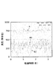
- FIG. 3 shows the measurement results of the odor sensor, and shows the results of the raw gas A and the released gas B discharged from the reformer 20. Since the released gas B was measured at two different locations, it was labeled as B1 and B2. The horizontal axis represents elapsed time (days), and the vertical axis represents the count value of the odor sensor.
- the count is 500 or less, even if it is released into the atmosphere as it is, no odor will be felt when it is more than 50 m away from the system. In the state of original gas A, a pungent odor is felt even if the distance from the system is more than 200 m.
- the pungent odor can be removed from the released gas B.
- Raw gas A is a mixed gas of mineral spirits and terpineol.
- trimethylbenzene and nonane are considered to be the main causes of the pungent odor. That is, from the result of FIG. 3, it is considered that the treatment system significantly reduces trimethylbenzene and nonane in the released gas B.
- terpineol is contained in a large amount in the steam regeneration gas when the catalyst is regenerated, it is easily adsorbed on the catalyst, mixed and diluted during steam regeneration, and the pungent odor is also reduced.
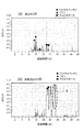
- FIG. 4 shows the results of the investigation of the released gas B by gas chromatograph mass spectrometry (TD-GC/MS method).
- FIG. 4A shows the result of the discharged gas B
- FIG. 4B shows the result of the inspection of the waste mixed gas D accompanied with the adsorbed component C by spraying the regeneration vapor R.
- trimethylbenzene is indicated by a triangle ( ⁇ )
- nonane is indicated by a square ( ⁇ )
- terpineol is indicated by a circle ( ⁇ ).
- trimethylbenzene, nonane, and terpineol are detected in the released gas B. These are the components of the raw gas A that have passed through the reformer 20. Although trimethylbenzene and nonane, which cause odor, remain, from the results shown in FIG. 3, if the leakage is to this extent, it may be released into the atmosphere as it is, and the concentration is below the so-called specified value.
- the trimethylbenzene and nonane captured by the reforming device 20 were reformed into other substances. It is considered that the substance X surrounded by a dotted line in FIG. These are substances (peaks) that were not originally contained in the raw gas A. Although the substance X is not specified, it can be said to be a harmless substance because it burns with terpineol without any problem.
- the method for treating a volatile organic compound according to the present invention can be suitably used for concentrating a solvent having a low flash point.
Landscapes
- Chemical & Material Sciences (AREA)
- Engineering & Computer Science (AREA)
- Chemical Kinetics & Catalysis (AREA)
- Environmental & Geological Engineering (AREA)
- Oil, Petroleum & Natural Gas (AREA)
- General Chemical & Material Sciences (AREA)
- Analytical Chemistry (AREA)
- Organic Chemistry (AREA)
- Biomedical Technology (AREA)
- Health & Medical Sciences (AREA)
- Materials Engineering (AREA)
- Sustainable Development (AREA)
- Life Sciences & Earth Sciences (AREA)
- Exhaust Gas Treatment By Means Of Catalyst (AREA)
Abstract
引火性の高い引火性溶剤を含む有機溶剤を濃縮して燃焼させる場合に、濃縮する際に発火する危険性があった。 揮発性有機化合物を含む原ガスを触媒に吸着させると共に、前記原ガスの一部を前記触媒で改質し放出する工程と、前記触媒に蒸気を通過させ、前記触媒の吸着成分を前記触媒から脱離させる工程と、前記吸着成分と前記蒸気の混合ガスを燃焼させる工程を有することを特徴とする揮発性有機化合物の処理方法は、触媒の吸着成分を蒸気と共に触媒から脱離させるので、発火の危険がすくなくなる。
Description
本発明は積層セラミックコンデンサの製造工程において、粉体と有機溶剤をスラリー状態にし、バインダーとして用いる有機溶剤が引火性の揮発性有機化合物であり、その処理方法およびその方法を実施するシステムに係るものである。特にミネラルスピリットとテルピネオールとの混合溶媒が製造工程で気化し、刺激臭を有する。その排ガスの脱臭を含めて処理する場合に好適に利用できる。
有機化合物のうち、揮発性有機化合物(以下「有機溶剤」と呼ぶ。)はさまざまな分野で利用され(例えば特許文献1)、有用な効果を奏している。しかし、有機溶剤は最終的には揮発させる。そして、排出される有機溶剤は自然環境に対して大きな環境負荷となる。
一方、人の健康を保護し生活環境を保全する上で維持されることが望ましい基準として、「環境基準」が環境基本法において設定されており、この環境基準を達成することを目標に、大気汚染防止法に基づいて規制を実施している。大気汚染防止法では、揮発性有機化合物についての排出基準等が定められている。
ミネラルスピリットは有機溶剤であり、刺激臭を有するものの、さまざまな溶質を溶解する際に用いられる。例えば、本発明で説明する場合のように、積層セラミックコンデンサの製造工程のスクリーン印刷に用いることができる。また、オフセット印刷の工程を有する場合は、高沸点溶剤と併用することで利用される。
このミネラルスピリットは、ベンゼンなど一部の組成を除いて、細かな成分内容は明確ではない。しかし、有機溶剤(VOC)として燃焼等によって最終処理を行い、自然界に排出基準値以下で放出する必要がある。
このような刺激臭を有する有機溶剤を処理するには、吸着させて濃縮し、燃焼させる方法がとられている。吸着には、活性炭等の多孔質体、キレート材、湿式スクラバー、又はハニカムローター式濃縮装置(特許文献2)といった濃縮装置が用いられる。これは吸着剤(例えば、ゼオライト)を入れたローターに有機溶剤を含む原ガスを通過させ、吸着剤に有機溶剤を吸着させ、乾燥熱風を用いてそれを脱離させ回収するというものである。
このような濃縮装置を用いると、有機溶剤の含有量の少ない原ガスであっても、濃縮器で濃縮してから脱離させるので、含有濃度の高い被処理ガスを得ることができ、効率的な燃焼処分を行うことができる。
しかし、引火性の高い物質(以下「引火性溶剤」と呼ぶ。)を含む有機溶剤を処理する場合、濃縮装置で濃縮を行うと、何等かのきっかけで発火するという問題があった。例えば、ミネラルスピリットは、JIS工業ガソリン4号に相当する石油系炭化水素の混合溶剤(ターペン・ミネラルスピリット)であり、有機溶剤中毒予防規則(労働安全衛生法)の第3種有機溶剤に該当し、特徴として刺激臭があり、引火点も低く(43℃)、爆発限界下限値は0.6Vol%、爆発限界上限値は8.0Vol%である引火性溶剤である。ミネラルスピリットは、複数の成分の混合物であり、全成分は明らかにされていない。しかし、トリメチルベンゼンと、ノナンが主原料となっている。したがって、臭気が強いという問題もあった。
本発明は上記の課題に鑑みて想到されたものであり、引火性溶剤を含む原ガスでも、発火の心配がなく濃縮し処理することができる揮発性有機化合物の処理方法である。
具体的に本発明に係る揮発性有機化合物の処理方法は、
揮発性有機化合物を含む原ガスを触媒に吸着させると共に、前記原ガスの一部を前記触媒で改質し放出する工程と、
前記触媒に蒸気を通過させ、前記触媒の吸着成分を前記触媒から脱離させる工程と、
前記吸着成分と前記蒸気の混合ガスを燃焼させる工程を有することを特徴とする。
揮発性有機化合物を含む原ガスを触媒に吸着させると共に、前記原ガスの一部を前記触媒で改質し放出する工程と、
前記触媒に蒸気を通過させ、前記触媒の吸着成分を前記触媒から脱離させる工程と、
前記吸着成分と前記蒸気の混合ガスを燃焼させる工程を有することを特徴とする。
本発明に係る揮発性有機化合物の処理方法では、原ガス中の揮発性有機化合物を触媒に吸着させることで前記揮発性有機化合物を濃縮する。そして、触媒に吸着した吸着成分を脱離させる際には、高温蒸気を用いて脱離させる。したがって、触媒から脱離した吸着成分は蒸気との混合ガスとなっている。この混合ガスは、熱量を周囲の蒸気中の水分が気化熱として吸収するため、引火しにくいガスとなる。この混合ガスはそのまま燃焼装置に送り燃焼させるので、発火の心配なく原ガス中の揮発性有機化合物を濃縮することができ、揮発性有機化合物を燃焼処理することができる。
また、触媒で吸着しきれなかった原ガスは、その一部若しくは全部が触媒で無害な有機物に改質され放出される。したがって、放出ガス中の原ガスの揮発性有機化合物の残量は、改質された分だけ少なくなり、大気放出中の原ガス中の揮発性有機化合物の残量を十分に少なくすることができる。
特に原ガス中で刺激臭の原因であるトリメチルベンゼンおよびノナンが改質によって他の物質になり、放出ガスの刺激臭は、知覚できない程度に低減される。
以下に本発明に係る揮発性有機化合物の処理方法について説明する。以下の説明は本発明の一実施形態を説明するものであり、本発明は以下の説明に限定されるものではない。本発明の趣旨を逸脱しない限りにおいて、以下の実施形態は改変することができる。
本発明で処理対象とする引火性溶剤(揮発性有機化合物)は、引火点が40℃乃至50℃のものである。そして引火性溶剤を、10質量%乃至40質量%含む原ガスが好適な処理対象となる。引火性溶剤の濃度が高い場合は、原ガスを濃縮する必要はなく、そのまま燃焼すればよい。また、引火性溶剤の含有比率が少なければ、そもそも発火の恐れがなく、従来技術のように、濃縮ガスを得ればよい。
次に、本発明に起因する積層セラミックコンデンサの製造工程を簡単に説明する。Ba及びTiを主成分とするセラミック材料粉末を含む複数のセラミックグリーンシートを用意し、このセラミックグリーンシート上に、Niを導電成分の主成分とする導電性ペーストをスクリーン印刷により塗布する。
このスクリーン印刷工程で有機溶剤であるミネラルスピリットを用い、内部電極となる導電性ペースト膜を形成する。このときに引火性溶剤であるミネラルスピリットは導電性ペーストとしての役割を有するが、揮発して工場内(以後「現場」とも呼ぶ。)の排気ダクトで集められる。
また、積層セラミックコンデンサの製造工程では、導電性ペースト膜が形成されていないセラミックグリーンシートを、所定の外層厚みになるように積層する。次いで、導電性ペースト膜が形成されたセラミックグリーンシートを所定枚数積層する。さらに、導電性ペーストが形成されていないセラミックグリーンシートを所定の外層厚みになるように積層することによって、複数の部品本体を取り出すことが可能な生の状態のマザーブロックを得る。
このマザーブロックを切断し、複数のチップ状部品を取出し、この部品をバッチ炉において還元性雰囲気下で焼成し、焼結したチップ状部品を得る。この焼成の際にも導電性ペースト中の溶剤であるミネラルスピリットは蒸発し、排気ダクトで集められる。
他方では、平均粒径約1.0μmの銅粉末と、ガラスフリットに対して、テルピネオールを主成分とする有機溶剤と、この有機溶剤に、アクリル系バインダーを溶解させたワニスを含む混合物を混ぜ、これを分散・混合処理することによって、外部電極用導電性ペーストを作製しておく。
この外部電極用導電性ペーストは所定の厚みで膜状に形成しておく。この導電性ペースト膜中に、ホルダによって保持された上述のチップ状部品の端部を浸漬後、導電性ペースト膜から取り出すことによって、部品本体の両端面に外部電極となる導電性ペーストを塗布する。この工程でテルピネオールは揮発する成分が発生し、排気ダクトで集められる。
次に外部電極となる導電性ペーストを焼付けるため、部品本体を炉で熱処理、約900℃の温度を10分間保持する。その後、降温して積層セラミックコンデンサを得るものである。この熱処理時に外部電極用導電性ペースト中のテルピネオールは蒸発し、排気ダクトで集められる。
このように、ミネラルスピリット(引火点:43℃)、テルピネオール(引火点:82℃)含有の排ガスは排気ダクト内で混合する。これを「原ガスA」と呼ぶ。この混合した状態であってもミネラルスピリットの気化ガスは引火性を有している。そこで、本発明に係る揮発性有機化合物の処理方法により、引火性の高い原ガスAを安全に処理していく。このように、原ガスA中の揮発性有機化合物は、ミネラルスピリットおよびテルピネオールを含む。
本発明の揮発性有機化合物の処理方法では、原ガスA中の揮発性有機化合物を触媒に吸着させ引火性溶剤を触媒に吸着させ除去する。この際に、揮発性有機化合物は触媒上に濃縮される。そして、一部の揮発性有機化合物は改質される。
触媒上に吸着された吸着成分Cは蒸気で触媒から脱離させる。この蒸気は触媒を再生させるという意味で再生用蒸気Rと呼ぶ。吸着成分Cは揮発性有機化合物と、後述するように触媒で改質された無害物質を含む。なお、ここで無害物質とは、引火性が低く、臭気も強くないもので、引火性および臭気を確認できなくても、発火などの問題なく燃焼できれば足りる。
吸着成分Cは再生用蒸気Rによって触媒から脱離させられるので、脱離した際には周囲にミスト状の水分が多量に存在する。したがって、急激な熱量の増加があれば、容易に蒸発し熱量を奪う。つまり、吸着成分Cと再生用蒸気Rの廃棄混合ガスDは、引火しにくいガスである。このように、一度触媒に吸着させ、蒸気で脱離させることで、引火性溶剤であっても、安全に処理することができる。廃棄混合ガスDはそのまま燃焼装置で燃焼させる。
一方、原ガスAの揮発性有機化合物は触媒で吸着しきれないものもある。吸着しきれなかった揮発性有機化合物があったとしても、規定された濃度以下の場合は、安全なガスとして大気中に放出することができる。そこで本発明の揮発性有機化合物の処理方法では、吸着に触媒を使用し、吸着できなかった揮発性有機化合物を改質し無臭で無害な物質に変えて放出する。
より具体的な例で説明すると、触媒で吸収しきれなかった揮発性有機化合物の量(これを「未吸収量」と呼ぶ。)がMあったとする。もちろんこのMは原ガスA中の揮発性有機化合物の総量からみれば、わずかな量であり、ほとんどの揮発性有機化合物は触媒に吸着される。したがって、未吸収量の全てが揮発性有機化合物であっても、規定の量を下回る。
具体的に説明すると、未吸収量の50%が触媒で改質された無害ガスになったとすると、原ガスA中の揮発性有機化合物の総量に対して未吸収量の揮発性有機化合物は、M/2にすることができる。このようにして、原ガスA中の揮発性有機化合物の吸着体として触媒を用いることで、触媒を通過したガス中の揮発性有機化合物の残量を低減させることができる。なお、触媒を通過したガスを「放出ガスB」と呼ぶ。放出ガスBはこのまま大気中に放出するこができる。
吸着および改質用の触媒は、特に限定されるものではない。白金、ルテニウム、パラジウム、ロジウム、アルミナ、マンガンといった代表的な触媒となる物質の単独、混合若しくは合金を利用することができる。触媒は、引火性溶剤の少なくとも一部を改質し、引火点をより高い物質にできればよい。濃縮の工程での発火を抑制できればよいからである。
特に、ミネラルスピリットとテルピネオールを揮発性有機化合物として含む原ガスAでは、アルミナのハニカム形状を触媒として好適に用いることができる。
その理由は、触媒表面の温度を高温にすることなく触媒機能を有する金属として、アルミナのハニカム形状やマンガンのハニカム形状が有効だからである。白金、パラジウムは触媒表面温度を高くしないと触媒機能が活性しない。一方、アルミナ、マンガンは、排気ガス中の空気との化学反応(酸化作用)も利用して、触媒表面の温度を180℃以上、300℃以下で改質できる。
また、アルミナ(γ-Al2O3)はアルコールの脱水反応に対して高い活性を持つことは古くから知られている。アルミナは、アルコール類の脱水反応の他にも極性分子の脱離反応、炭化水素の異性化、水素交換反応に使われている。そして、アルミナは、今回の混合溶剤の炭化水素の異性化(低分子化)にも好適に利用できる。
図1に、本発明に係る揮発性有機化合物の処理方法を実施する揮発性有機化合物の処理システム1の構成を示す。現場10において、媒質を溶解している混合溶剤は、蒸発させられ原ガスAとなる。原ガスAは、具体的にはミネラルスピリットとテルピネオールを含む混合ガスである。現場10からはダクト等を経由して改質装置20および改質装置22に連通している。途中に風圧を供給するためのブロア31が設けられていてもよい。
また、原ガスAには外気Wcを混ぜる冷気混合器34が設けられていてもよい。原ガスAが改質装置20及び改質装置22に流入する際に温度が上昇するのを抑制することと、原ガスAの容積当たりの濃度を低くするためである。原ガスAが送風されるダクトに冷却器を設けてもよい。また冷却器は、改質装置20及び改質装置22に個々に設けてもよい。これらは、原ガスAを冷却する冷却手段と呼ぶ。原ガスAを冷却しておくことで、触媒に原ガスAが吸収され濃縮された際に、引火しにくくすることができる。
改質装置20及び改質装置22の現場10側には、切換装置41が配置されている。なお切換装置41はモーターダンパーや、バルブでよい。改質装置20および改質装置22の出口側には、切換装置42が設けられている。切換装置42はモーターダンパーや、バルブでよい。切換装置41と切換装置42の動きは連動している。つまり、原ガスAを改質装置20若しくは改質装置22の何れかに通過させ、放出ガスBとして放出するように動作する。なお、改質装置は3台以上備わっていてもよい。その場合は、切換装置41および切換装置42の部分がさらに分岐し、いずれかの改質装置に原ガスAを送り、放出ガスBとして放出させる。
改質装置20および改質装置22は、触媒が充填された容器であり、触媒の再生用蒸気Rを供給する蒸気供給源18が連結されている。また、蒸気供給源18と改質装置20および改質装置22の間にはバルブ43が配置されており、再生用蒸気Rを改質装置20若しくは改質装置22の何れかに供給できる。
図2には、改質装置20(改質装置22も全く同じ構造でよい)の内部構造を示す。図2(a)は、原ガスAを改質している状態を表し、図2(b)は、触媒26を再生している状態を示す。改質装置20内には、触媒26が充填されている。改質装置20の下方には、原ガスAの取り入れ口23iが形成され、改質装置20の上方には、放出ガスBの放出口23oが設けられている。
また、改質装置20の内面上部には、再生用蒸気Rの噴出口24iが形成されている。また、改質装置20の下部には、排出口24oが設けられている。
再び図1を参照して、改質装置20および改質装置22の放出口23oからは放出ガスBが、大気に放出される。また、改質装置20および改質装置22の排出口24oは燃焼装置16に連通する。燃焼装置16の排気はそのまま大気に排出される。
以上の構成を有する揮発性有機化合物の処理システム1の動作について図1および図2を参照しながら説明する。現場10で発生した原ガスAは、ブロア31で後段の改質装置20(若しくは改質装置22)に送られる。この際に原ガスAに冷気Wcを加える、若しくはダクトを冷やす等して、原ガスAを冷却してもよい。
改質装置20の取り入れ口23iから内部に導入された原ガスA中の揮発性有機化合物は、触媒26の間を通過することで、触媒26に吸着される。また、一部は改質され物質構造が変化し、引火点が高くなり無臭で無害なガスとなる。触媒26を通過した原ガスAは、放出ガスBとなる。放出ガスBは、空気と揮発性有機化合物および改質された揮発性有機化合物で構成される。揮発性有機化合物および改質された揮発性有機化合物は放出ガスBに対して十分微量(排出基準値以下の量)となる。放出ガスBは、そのまま放出される。
触媒26を通過した原ガスA中の揮発性有機化合物は全て吸着されることはなく、触媒26の状態により一部は触媒26を通過する。しかし、その一部が改質されることで、実質的な揮発性有機化合物の排出量を低減させることができる。
次に改質装置22について説明する。改質装置20および改質装置22中の触媒26は、多孔質体であるため、触媒作用とともに、吸着作用も行う。従って、原ガスA中の揮発性有機化合物は、この吸着作用によって、触媒26に吸着される。結果、触媒26の表面を覆い、触媒作用を阻害するようになる。
そこで、一定時間毎に、改質装置20と改質装置22を入れ替え、触媒26の表面が覆われてしまった方の改質装置は再生用蒸気Rで触媒26の表面から吸着成分Cを脱離させる。この改質装置20と改質装置22との切り替えは、連動して動作する切換装置41および切換装置42で行う。また、切換装置の切り換えは一定時間毎に切り換えてもよいし、放出口23oに有機物センサを設けて放出ガスB中の引火性溶剤の濃度によって切り換えてもよい。
図2(b)を参照して、蒸気供給源18から供給された再生用蒸気Rは、噴出口24iから触媒26に吹き付けられ、触媒26表面の吸着成分を脱離させる。脱離された吸着成分Cは、蒸気と吸着成分Cが混ざった廃棄混合ガスDとなって排出口24oから排出される。廃棄混合ガスD中の蒸気には、ミストが存在するので、熱量を吸収しやすく、引火しにくい状態となっている。したがって、濃縮された揮発性有機化合物が吸着成分C中に残留していても、引火の心配なく脱離排出することができる。
触媒26表面の吸着成分Cが除去された改質装置は、他方の改質装置の触媒26表面が使用によって溶剤成分で覆われた後に、入れ替えられる。すなわち、揮発性有機化合物の処理は連続して継続することができる。なお、廃棄混合ガスDは、燃焼装置16に送られ燃焼処理される。
以上のように、本発明に係る揮発性有機化合物の処理システム1は、改質装置を複数用意し、触媒機能が低下してくると、新しい改質装置と入れ替えて処理能力を維持する。入れ替えられた改質装置の触媒は別途再生され、また入れ替えて使用される。
以下に実施例を示して本発明に係る揮発性有機物の処理方法および処理システムの効果について説明する。
図1および2の構成を有する処理システム(排気ダクトを50cm×50cmで、処理装置の面風速を3.0m/secとした場合)を用いた放出ガスBがおよそ45m3/min程度の処理量である。面風速を一般に用いる1.0m/secにするより、3.0m/secと、風速を3倍とすることで、排ガスが改質装置に送られる時間が短縮することができる。
図3は、臭気センサの測定結果であり、原ガスAと、改質装置20を出た放出ガスBの結果を示す。なお、放出ガスBは場所が異なる2箇所の位置で測定したので、符号B1およびB2と表示した。横軸は経過時間(日)を表し、縦軸は臭気センサのカウント値である。
カウント500以下であれば、そのまま大気放出しても、システムから50m以上離れると臭気を感じることはなくなる。原ガスAの状態であれば、システムから200m以上はなれても、刺激臭を感じる。
図3に示すように、本発明に係る処理システムを用いると、放出ガスBからは刺激臭を除去することができる。原ガスAは、ミネラルスピリットとテルピネオールの混合ガスである。このなかで刺激臭の主な原因となっているのは、トリメチルベンゼンとノナンと考えられる。つまり、図3の結果より、処理システムは放出ガスB中のトリメチルベンゼンとノナンを著しく減少させていると考えられる。
また、テルピネオールは触媒の再生時の蒸気再生ガスに多く含まれていることから、触媒に吸着しやすく、蒸気再生時に混合希釈され、刺激臭も軽減される。
図4には、放出ガスBのガスクロマトグラフ質量分析法(TD-GC/MS法)で調べた結果を示す。図4(a)は、放出ガスBの結果であり、図4(b)は再生用蒸気Rを吹き付け吸着成分Cを伴った廃棄混合ガスDの検査結果である。図中、トリメチルベンゼンは三角印(▲)、ノナンは四角印(■)、テルピネオールは丸印(●)で表した。
図4(a)を参照して、放出ガスB中には、トリメチルベンゼン、ノナン、テルピネオールが検出されている。これらは改質装置20を通り抜けてきた原ガスAの成分である。臭気の原因となるトリメチルベンゼン、ノナンは残っているものの、図3の結果より、この程度の漏れであれば、そのまま大気に放出してもよく、所謂規定値以下の濃度である。
一方図4(b)を参照すると、廃棄混合ガスD中には、テルピネオールは検出されるものの、トリメチルベンゼン、ノナンは存在しなかった。原ガスAは強い刺激臭が確認されるので、多量のトリメチルベンゼンおよびノナンが存在していると考えられる。また、放出ガスB中には、臭気が感知できない程度にしか、トリメチルベンゼンおよびノナンは残留していなかった。すると、残りのトリメチルベンゼンおよびノナンは、改質装置20中に捕捉されていると思われるが、廃棄混合ガスD中には、存在しなかったのである。
すなわち、改質装置20で捕捉されたトリメチルベンゼンおよびノナンは、改質され、他の物質になったと考えられる。図4(b)では点線で囲った物質Xになったと考えられる。これらは、そもそも原ガスA中にはなかった物質(ピーク)である。物質Xは特定されていないが、テルピネオールと共に、問題なく燃焼されるので、無害物質であるといえる。
本発明に係る揮発性有機化合物の処理方法は、引火点の低い溶剤を濃縮する場合に好適
に利用することができる。
に利用することができる。
1 揮発性有機化合物の処理システム
10 現場
16 燃焼装置
18 蒸気供給源
20 改質装置
22 改質装置
23i 取り入れ口
23o 放出口
24i 噴出口
24o 排出口
26 触媒
31 ブロア
41 切換装置
42 切換装置
43 バルブ
A 原ガス
B 放出ガス
D 廃棄混合ガス
R 再生用蒸気
10 現場
16 燃焼装置
18 蒸気供給源
20 改質装置
22 改質装置
23i 取り入れ口
23o 放出口
24i 噴出口
24o 排出口
26 触媒
31 ブロア
41 切換装置
42 切換装置
43 バルブ
A 原ガス
B 放出ガス
D 廃棄混合ガス
R 再生用蒸気
Claims (11)
- 揮発性有機化合物を含む原ガスを触媒に吸着させると共に、前記原ガスの一部を前記触媒で改質し放出する工程と、
前記触媒に蒸気を通過させ、前記触媒の吸着成分を前記触媒から脱離させる工程と、
前記吸着成分と前記蒸気の混合ガスを燃焼させる工程を有することを特徴とする揮発性有機化合物の処理方法。 - 前記揮発性有機化合物がミネラルスピリットとテルピネオールの混合溶剤であることを特徴とする請求項1に記載された揮発性有機化合物の処理方法。
- 前記触媒は、アルミナとチタンで形成されていることを特徴とする請求項2に記載された揮発性有機化合物の処理方法。
- 前記原ガスを前記触媒に接触させる前に前記原ガスを冷却する工程を有することを特徴とする請求項1乃至3の何れか一の請求項に記載された揮発性有機化合物の処理方法。
- 前記触媒は、トリメチルベンゼンおよびノナンを無害物質に改質することを特徴とする請求項1乃至4の何れか一の請求項に記載された揮発性有機化合物の処理方法。
- 揮発性有機化合物を含む原ガスを触媒に吸着させると共に、前記原ガスの一部を前記触媒で改質し放出する改質装置と、
前記改質装置内の前記触媒に蒸気を供給し、前記触媒の吸着成分を前記触媒から脱離させる再生蒸気供給器と、
前記吸着成分と前記蒸気の廃棄混合ガスを燃焼させる燃焼装置を有する揮発性有機化合物の処理システム。 - 前記改質装置を複数台備え、前記改質装置を切り換える切換装置を有することを特徴とする請求項6に記載された揮発性有機化合物の処理システム。
- 前記原ガスを前記触媒に吸着させる前に冷却する冷却手段を有することを特徴とする請求項6また7の何れかに記載された揮発性有機化合物の処理システム。
- 前記揮発性有機化合物がミネラルスピリットとテルピネオールの混合溶剤であることを特徴とする請求項6乃至8の何れか一の請求項に記載された揮発性有機化合物の処理システム。
- 前記改質装置は、前記原ガスを通過させるアルミナ触媒を有することを特徴とする請求項6乃至9の何れか一の請求項に記載された揮発性有機化合物の処理システム。
- 前記改質装置は、トリメチルベンゼンおよびノナンを無害物質に改質することを特徴とする請求項6乃至10の何れか一の請求項に記載された揮発性有機化合物の処理システム。
Priority Applications (1)
| Application Number | Priority Date | Filing Date | Title |
|---|---|---|---|
| JP2020504252A JP6687822B1 (ja) | 2018-12-03 | 2019-09-27 | 揮発性有機化合物の処理方法および処理システム |
Applications Claiming Priority (2)
| Application Number | Priority Date | Filing Date | Title |
|---|---|---|---|
| JP2018-226576 | 2018-12-03 | ||
| JP2018226576 | 2018-12-03 |
Publications (1)
| Publication Number | Publication Date |
|---|---|
| WO2020116003A1 true WO2020116003A1 (ja) | 2020-06-11 |
Family
ID=70974574
Family Applications (1)
| Application Number | Title | Priority Date | Filing Date |
|---|---|---|---|
| PCT/JP2019/038327 Ceased WO2020116003A1 (ja) | 2018-12-03 | 2019-09-27 | 揮発性有機化合物の処理方法および処理システム |
Country Status (1)
| Country | Link |
|---|---|
| WO (1) | WO2020116003A1 (ja) |
Citations (8)
| Publication number | Priority date | Publication date | Assignee | Title |
|---|---|---|---|---|
| JPS5168988A (ja) * | 1974-12-13 | 1976-06-15 | Hitachi Ltd | |
| JPS5580527A (en) * | 1978-12-08 | 1980-06-17 | Nitto Shoji Kk | Collector holder for fine spinning |
| JPH01139124A (ja) * | 1987-11-24 | 1989-05-31 | Nitto Denko Corp | ケトン系溶剤の回収精製方法 |
| JP2000123634A (ja) * | 1998-08-10 | 2000-04-28 | Vacuum Metallurgical Co Ltd | Cu超微粒子独立分散液 |
| US20110158872A1 (en) * | 2009-11-03 | 2011-06-30 | Ariya Parisa A | Method and System for Adsorbing Pollutants and/or Contaminants |
| JP2011194398A (ja) * | 2010-02-25 | 2011-10-06 | Toyobo Co Ltd | 有機溶剤回収装置 |
| JP2014147865A (ja) * | 2013-01-31 | 2014-08-21 | Toyobo Co Ltd | ガス処理装置およびガス処理方法 |
| JP2016007596A (ja) * | 2014-06-26 | 2016-01-18 | 株式会社栗本鐵工所 | 揮発性有機化合物処理装置の制御方法 |
-
2019
- 2019-09-27 WO PCT/JP2019/038327 patent/WO2020116003A1/ja not_active Ceased
Patent Citations (8)
| Publication number | Priority date | Publication date | Assignee | Title |
|---|---|---|---|---|
| JPS5168988A (ja) * | 1974-12-13 | 1976-06-15 | Hitachi Ltd | |
| JPS5580527A (en) * | 1978-12-08 | 1980-06-17 | Nitto Shoji Kk | Collector holder for fine spinning |
| JPH01139124A (ja) * | 1987-11-24 | 1989-05-31 | Nitto Denko Corp | ケトン系溶剤の回収精製方法 |
| JP2000123634A (ja) * | 1998-08-10 | 2000-04-28 | Vacuum Metallurgical Co Ltd | Cu超微粒子独立分散液 |
| US20110158872A1 (en) * | 2009-11-03 | 2011-06-30 | Ariya Parisa A | Method and System for Adsorbing Pollutants and/or Contaminants |
| JP2011194398A (ja) * | 2010-02-25 | 2011-10-06 | Toyobo Co Ltd | 有機溶剤回収装置 |
| JP2014147865A (ja) * | 2013-01-31 | 2014-08-21 | Toyobo Co Ltd | ガス処理装置およびガス処理方法 |
| JP2016007596A (ja) * | 2014-06-26 | 2016-01-18 | 株式会社栗本鐵工所 | 揮発性有機化合物処理装置の制御方法 |
Similar Documents
| Publication | Publication Date | Title |
|---|---|---|
| JP4873822B2 (ja) | 炭化水素トラップ/触媒組成物 | |
| KR101542177B1 (ko) | Voc 흡착농축식 촉매산화 처리장치 | |
| CN103349962B (zh) | 耐臭氧氧化的低浓度有机化合物吸附催化材料及其制备方法 | |
| CN102814099A (zh) | 用以净化总挥发性有机物的装置及方法 | |
| KR101468634B1 (ko) | 전기집진기 및 흡착-저온산화촉매를 이용한 휘발성 유기화합물 및 악취제거 시스템 | |
| CN108786449A (zh) | 一种新型V0Cs吸附活化脱附低温催化处理方法及其处理装置 | |
| CN102614874A (zh) | 一种氧化铝浆料的制备方法、含有该氧化铝浆料的汽车尾气净化催化剂及其制备方法 | |
| JP5199076B2 (ja) | 水素製造におけるドレン水の処理方法および水素製造システム | |
| WO2011114978A1 (ja) | 二酸化炭素回収装置からの排ガスの処理方法及び装置 | |
| Wang et al. | An energy-efficient catalytic process for the tandem removal of formaldehyde and benzene by metal/HZSM-5 catalysts | |
| JP6687822B1 (ja) | 揮発性有機化合物の処理方法および処理システム | |
| JP2007237041A (ja) | 有機溶剤含有空気の処理方法 | |
| WO2020116003A1 (ja) | 揮発性有機化合物の処理方法および処理システム | |
| CN111467928A (zh) | 基于活性炭吸附浓缩-催化燃烧技术处理汽车行业喷涂有机废气的方法及系统 | |
| TW201622802A (zh) | 藉由錳系混合物而氧化有害性化合物的方法及錳系混合物 | |
| WO2005054126A1 (ja) | 炭素材料及び排煙処理装置 | |
| CN107261664A (zh) | 一种合成革工艺中废气和废液的联合处理工艺 | |
| Liu et al. | On “Storage‐Oxidation” Cycling Removal of BTX Over Zeolite Composites | |
| CN205700032U (zh) | 废气处理用活性炭吸附与再生装置 | |
| JP2020515005A (ja) | 脱硫吸着物の熱再生を行う燃料電池システム及び方法 | |
| CN101362042B (zh) | 含有稀薄挥发性碳氢化合物的大量废气的净化装置 | |
| JP4847118B2 (ja) | 希薄な揮発性炭化水素を含む大量の排ガス浄化方法 | |
| CN104399361B (zh) | 一种辊道窑烧成泡沫陶瓷过滤器的废气处理方法及装置 | |
| JPH0155888B2 (ja) | ||
| JP2009142719A (ja) | 揮発性有機物回収処理装置及びこれを有する揮発性有機物回収処理システム |
Legal Events
| Date | Code | Title | Description |
|---|---|---|---|
| ENP | Entry into the national phase |
Ref document number: 2020504252 Country of ref document: JP Kind code of ref document: A |
|
| 121 | Ep: the epo has been informed by wipo that ep was designated in this application |
Ref document number: 19893380 Country of ref document: EP Kind code of ref document: A1 |
|
| NENP | Non-entry into the national phase |
Ref country code: DE |
|
| 122 | Ep: pct application non-entry in european phase |
Ref document number: 19893380 Country of ref document: EP Kind code of ref document: A1 |