WO2020115960A1 - 圧力変動吸収構造体及び圧力変動抑制用の薄膜 - Google Patents
圧力変動吸収構造体及び圧力変動抑制用の薄膜 Download PDFInfo
- Publication number
- WO2020115960A1 WO2020115960A1 PCT/JP2019/033834 JP2019033834W WO2020115960A1 WO 2020115960 A1 WO2020115960 A1 WO 2020115960A1 JP 2019033834 W JP2019033834 W JP 2019033834W WO 2020115960 A1 WO2020115960 A1 WO 2020115960A1
- Authority
- WO
- WIPO (PCT)
- Prior art keywords
- thin film
- sound absorbing
- sound
- pressure fluctuation
- absorbing panel
- Prior art date
- Legal status (The legal status is an assumption and is not a legal conclusion. Google has not performed a legal analysis and makes no representation as to the accuracy of the status listed.)
- Ceased
Links
Images














Classifications
-
- B—PERFORMING OPERATIONS; TRANSPORTING
- B32—LAYERED PRODUCTS
- B32B—LAYERED PRODUCTS, i.e. PRODUCTS BUILT-UP OF STRATA OF FLAT OR NON-FLAT, e.g. CELLULAR OR HONEYCOMB, FORM
- B32B5/00—Layered products characterised by the non- homogeneity or physical structure, i.e. comprising a fibrous, filamentary, particulate or foam layer; Layered products characterised by having a layer differing constitutionally or physically in different parts
- B32B5/22—Layered products characterised by the non- homogeneity or physical structure, i.e. comprising a fibrous, filamentary, particulate or foam layer; Layered products characterised by having a layer differing constitutionally or physically in different parts characterised by the presence of two or more layers which are next to each other and are fibrous, filamentary, formed of particles or foamed
- B32B5/32—Layered products characterised by the non- homogeneity or physical structure, i.e. comprising a fibrous, filamentary, particulate or foam layer; Layered products characterised by having a layer differing constitutionally or physically in different parts characterised by the presence of two or more layers which are next to each other and are fibrous, filamentary, formed of particles or foamed at least two layers being foamed and next to each other
-
- B—PERFORMING OPERATIONS; TRANSPORTING
- B64—AIRCRAFT; AVIATION; COSMONAUTICS
- B64C—AEROPLANES; HELICOPTERS
- B64C1/00—Fuselages; Constructional features common to fuselages, wings, stabilising surfaces or the like
- B64C1/40—Sound or heat insulation, e.g. using insulation blankets
-
- B—PERFORMING OPERATIONS; TRANSPORTING
- B64—AIRCRAFT; AVIATION; COSMONAUTICS
- B64D—EQUIPMENT FOR FITTING IN OR TO AIRCRAFT; FLIGHT SUITS; PARACHUTES; ARRANGEMENT OR MOUNTING OF POWER PLANTS OR PROPULSION TRANSMISSIONS IN AIRCRAFT
- B64D33/00—Arrangement in aircraft of power plant parts or auxiliaries not otherwise provided for
-
- G—PHYSICS
- G10—MUSICAL INSTRUMENTS; ACOUSTICS
- G10K—SOUND-PRODUCING DEVICES; METHODS OR DEVICES FOR PROTECTING AGAINST, OR FOR DAMPING, NOISE OR OTHER ACOUSTIC WAVES IN GENERAL; ACOUSTICS NOT OTHERWISE PROVIDED FOR
- G10K11/00—Methods or devices for transmitting, conducting or directing sound in general; Methods or devices for protecting against, or for damping, noise or other acoustic waves in general
- G10K11/16—Methods or devices for protecting against, or for damping, noise or other acoustic waves in general
-
- G—PHYSICS
- G10—MUSICAL INSTRUMENTS; ACOUSTICS
- G10K—SOUND-PRODUCING DEVICES; METHODS OR DEVICES FOR PROTECTING AGAINST, OR FOR DAMPING, NOISE OR OTHER ACOUSTIC WAVES IN GENERAL; ACOUSTICS NOT OTHERWISE PROVIDED FOR
- G10K11/00—Methods or devices for transmitting, conducting or directing sound in general; Methods or devices for protecting against, or for damping, noise or other acoustic waves in general
- G10K11/16—Methods or devices for protecting against, or for damping, noise or other acoustic waves in general
- G10K11/162—Selection of materials
- G10K11/168—Plural layers of different materials, e.g. sandwiches
-
- G—PHYSICS
- G10—MUSICAL INSTRUMENTS; ACOUSTICS
- G10K—SOUND-PRODUCING DEVICES; METHODS OR DEVICES FOR PROTECTING AGAINST, OR FOR DAMPING, NOISE OR OTHER ACOUSTIC WAVES IN GENERAL; ACOUSTICS NOT OTHERWISE PROVIDED FOR
- G10K11/00—Methods or devices for transmitting, conducting or directing sound in general; Methods or devices for protecting against, or for damping, noise or other acoustic waves in general
- G10K11/16—Methods or devices for protecting against, or for damping, noise or other acoustic waves in general
- G10K11/172—Methods or devices for protecting against, or for damping, noise or other acoustic waves in general using resonance effects
Definitions
- the present invention is applied to, for example, a pressure fluctuation absorbing structure installed on an inner wall of a duct for damping fan noise, combustor noise, and turbine noise of a jet engine in a noise propagation path, and such a pressure fluctuation absorbing structure.
- a pressure fluctuation absorbing structure installed on an inner wall of a duct for damping fan noise, combustor noise, and turbine noise of a jet engine in a noise propagation path, and such a pressure fluctuation absorbing structure.
- a pressure fluctuation absorbing structure installed on an inner wall of a duct for damping fan noise, combustor noise, and turbine noise of a jet engine in a noise propagation path, and such a pressure fluctuation absorbing structure.
- the sound absorbing panel has a function of absorbing energy of sound waves incident on the surface.
- the sound absorbing panel basically has a three-layer structure including a panel surface, a surface plate, a cell structure, and a back wall.
- the surface plate is provided with holes, and the air contacting the surface plate is communicated with the cell structure through the holes.
- the resonance type sound absorbing panel has a function of enhancing sound absorbing performance under the acoustic resonance frequency determined by the above structure. Sound propagating in air generally forms a wave that is temporally reproducible according to frequency.
- a sound usually includes a sound having a plurality of frequencies and accompanying amplitudes and phases.
- the resonance type sound absorbing panel enhances sound absorbing performance in a frequency band centered on a specific frequency.
- JP, 2007-309326 A Japanese Patent Publication No. 2013-522511 Japanese Patent Publication No. 2011-530675 Japanese Patent Laid-Open No. 2006-2869 Japanese Patent Laid-Open No. 2002-337094 JP, 2010-84768, A JP, 2013-140248, A
- the inventors of the present invention obtained the following findings as a result of keen examination of the resonance type sound absorbing panel, because the sound absorbing performance as expected under static conditions cannot be obtained when an airflow exists on the panel surface.
- the presence of the airflow flowing on the panel surface, particularly the grazing flow flowing near the surface of the panel reduces the sound absorbing performance and also changes the resonance frequency. That is, when the grazing flow increases, the peak of the sound absorption coefficient decreases, while the frequency band of sound absorption tends to increase.
- the frequency (resonance frequency) corresponding to the peak of the sound absorption coefficient also changes as the grazing flow velocity increases.
- an object of the present invention is to provide a pressure fluctuation absorbing structure capable of suppressing a decrease in pressure fluctuation absorbing performance due to an air flow on the surface and a deviation in resonance frequency.
- Another object of the present invention is to provide a thin film for suppressing pressure fluctuation that can suppress pressure fluctuation without disturbing the flow of air currents on the surface.
- a pressure fluctuation absorbing structure is a perforated member provided with holes for pressure fluctuation absorption on the surface, and is arranged on the surface of the perforated member, at least the above.
- the air flow is generated on the surface.
- (Grazing flow) it is possible to suppress the decrease in sound absorption coefficient and the transition of resonance frequency, and the acoustic performance is improved as compared with the related art.
- a preferable mode is that the small holes have a hole diameter that allows pressure fluctuations to pass therethrough and regulates the permeation of surface fluid flow.
- the aspect ratio obtained by dividing the thickness of the thin film by the diameter of the small holes is smaller than 2.
- the diameter of the small holes is smaller than 1/2 of the diameter of the pressure fluctuation absorbing holes.
- the diameter of the small holes is preferably 0.6 mm or less.
- the diameter of the small holes is more preferably 0.15 mm to 0.35 mm or less with respect to the diameter of the pressure fluctuation absorbing holes of 1 to 1.5 mm, and the small hole diameter is 0.15 mm to 0.25 mm or less. More preferable.
- the plurality of small holes are substantially uniformly perforated in the thin film, and the aperture ratio of the thin film by the plurality of small holes is 15% or more.
- a preferable form is that the plurality of small holes are distributed in the area corresponding to the hole and around the area.
- a more preferable form is that the plurality of small holes are dispersed in a range of a diameter that is about three times the diameter of the region.
- the thin film has a laminated structure.
- the perforated member is a resonance type sound absorbing panel body such as a honeycomb type in which sound absorbing holes as pressure fluctuation absorbing holes are provided on the surface.
- the perforated member may be a pressure fluctuation absorbing material having holes for absorbing pressure fluctuations provided on the surface.
- the pressure fluctuation absorbing material is typically a porous material or a metal fiber sound absorbing material. For example, by sticking the thin film on the surface of the porous material, it is possible to suppress the boundary layer noise and reflected noise on the surface of the airframe while maintaining the flow around the airframe.
- the thin film for suppressing pressure fluctuation according to one embodiment of the present invention is formed with a large number of small holes having a pore diameter that allows pressure fluctuation to pass through and does not allow a surface fluid flow to pass through. As a result, the pressure fluctuation can be suppressed without disturbing the flow of the air flow on the surface.
- the thin film for suppressing pressure fluctuation according to an aspect of the present invention is arranged on the surface of a perforated member having a hole for absorbing pressure fluctuation provided on the surface or on the surface of a pressure fluctuation absorbing material.
- the present invention it is possible to suppress the deterioration of the pressure fluctuation absorption performance and the deviation of the resonance frequency due to the air flow on the surface.
- FIG. 2 is an enlarged vertical sectional view of a part of the sound absorbing panel 1 shown in FIG. 1.
- FIG. 3 is an enlarged view around a hole 14 of the sound absorbing panel 1 shown in FIG. 2.
- It is a schematic plan view which shows the other aspect of the shape of the small hole 21.
- It is a schematic plan view which shows the other form of distribution of the small hole 21.
- It is an enlarged view near the hole 14 which concerns on another form.
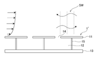
- FIG. 5B is a sectional view taken along line AA of FIG. 5A. It is a sectional view for explaining an operation of a general sound absorbing panel 1'.
- FIG. 6 is a schematic diagram showing composition of a flow duct type sound absorption performance testing device.
- 6 is a graph showing the sound absorption coefficient in the same direction as the main flow, which is the result of measuring the change in the sound absorption coefficient due to the Grazing flow of the sound absorbing panel 1 ′ to which the thin film 20 is not attached.
- 6 is a graph showing a sound absorption coefficient in a direction opposite to a main flow, which is a result of measurement of a change in sound absorption coefficient due to a Grazing flow of the sound absorbing panel 1′ to which the thin film 20 is not attached.
- the sound absorption rate of the sound absorbing panel 1 with the thin film 20 attached thereto and the sound absorbing panel 1'without the thin film 20 attached with the grazing flow (when the aperture ratios are 40% and 17%) were measured.
- 3 is a graph showing the results of measuring the sound absorption coefficient in the same direction as the mainstream, with the mainstream Mach number being 0.2.
- the sound absorption rate of the sound absorbing panel 1 with the thin film 20 and the sound absorbing panel 1'without the thin film 20 measured in the state of grazing flow (when the aperture ratio is 40% and 17%).
- FIG. 2 is a graph showing the results of measuring the sound absorption coefficient in the opposite direction to the mainstream, with the mainstream Mach number being 0.2.
- 3 is a graph showing the results of measuring the sound absorption coefficient in the same direction as the mainstream, with the mainstream Mach number being 0.3.
- the sound absorption rate of the sound absorbing panel 1 with the thin film 20 and the sound absorbing panel 1'without the thin film 20 measured in the state of grazing flow (when the aperture ratio is 40% and 17%).
- FIG. 3 is a graph showing the results of measuring the sound absorption coefficient in the direction opposite to the mainstream, with the mainstream Mach number being 0.3. It is a front view which shows the structure of the structure which concerns on other embodiment (the 1) of this invention. It is sectional drawing of FIG. 16A. It is a front view which shows the structure of the blade
- FIG. 21A It is sectional drawing which shows another example of the mobile body which concerns on other embodiment (the 4) of this invention. It is a schematic sectional drawing which shows an example of the structure which concerns on other embodiment (the 5) of this invention. It is a front view which shows the other example of the structure which concerns on other embodiment (the 5) of this invention. It is sectional drawing of FIG. 21A.
- FIG. 1A is an exploded perspective view showing a sound absorbing panel 1 as a pressure fluctuation absorbing structure according to an embodiment of the present invention.
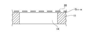
- FIG. 1B is an enlarged vertical sectional view of a part of the sound absorbing panel 1.
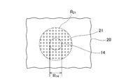
- FIG. 1C is an enlarged view of the vicinity of the hole 14.
- the sound absorbing panel 1 is configured by attaching a thin film 20 to the surface of the sound absorbing panel body 10 using, for example, an adhesive (not shown).
- the sound absorbing panel body 10 is provided with a sound absorbing hole 14 as a pressure fluctuation absorbing hole on its surface.
- the thin film 20 has a large number of small holes 21, and at least the region R 14 corresponding to the holes 14 has a plurality of small holes 21.
- the sound absorbing panel body 10 is a conventional resonance type sound absorbing panel, and has a function of absorbing energy of sound waves passing through the surface when there is no airflow on the surface.
- the surface of the sound absorbing panel body 10 may have not only a flat surface but also a curved surface or an arbitrary shape when viewed from the space side where the sound wave enters.
- the resonance type sound absorbing panel body 10 has a three-layer structure from the panel surface. These are recognized as the face plate 11, the cell structure 12, and the back wall 13.
- the surface plate 11 has holes 14 for absorbing sound, and the air contacting the surface plate 11 and the cell structure 12 are communicated with each other through the holes 14.
- the cell structure 12 is a small space surrounded by a surface plate 11, a back wall 13, and partition walls 15 that partition the cells. That is, the sound absorbing panel body 10 has a plurality of cell structures 12. Depending on the use of the sound absorbing panel body 10, a small hole for draining water that has penetrated into the cell may be provided in a part of the partition wall 15 that divides the cell. There is also a structure called a multi-layer sound absorbing panel, in which a small hole is provided in the back wall 13 and a cell and a back layer are provided behind it, that is, a so-called multi-layer sound absorbing panel. Since the cell structure 12 is sandwiched between the surface plate 11 and the back wall 13, it is sometimes called a “sandwich structure”.
- the cross-sectional shape of the cell structure 12 is arbitrary and may be triangular, quadrangular, polygonal or circular.
- the hexagonal one is specifically called a "honeycomb" structure.
- the cell structure 12 basically communicates with the outside through a hole 14 provided in the surface plate 11.
- the back wall 13 is assumed to have sufficient rigidity against vibration of air. Further, in the usual handling, all the partition walls 15 surrounding the cell structure 12 are treated as sufficiently rigid as compared with the air inside.
- the sound absorbing panel body 10 is of a resonance type and has a function of enhancing sound absorbing performance under an acoustic resonance frequency determined by the above structure.
- sound propagating in air forms waves that are reproducible in time with frequency.
- a sound usually includes a sound having a plurality of frequencies and accompanying amplitudes and phases.
- the resonance type sound absorbing panel body 10 enhances sound absorbing performance in a frequency band centered on a specific frequency.
- the resonance frequency f of the resonance type sound absorbing panel body 10 is the volume V of the cell structure 12, the total area s of the holes 14 of the surface plate 11 corresponding to the cells, and the length of the holes 14 (in other words, the surface plate 11).
- d is defined as follows.
- d' is a value obtained by adding an opening end correction amount to d.
- f c/2 ⁇ (s/Vd′)
- the air inside the hole 14 When the air inside the hole 14 is pushed to the cell structure 12 side, the air inside the cell structure 12 is compressed, the air inside the cell structure 12 is pulled into the inside of the hole 14, and the air inside the cell structure 12 is removed. Expands. However, since the volume of the hole 14 is sufficiently smaller than the volume of the cell structure 12, the volume change amount due to the compression and expansion is sufficiently smaller than the volume of the cell structure 12. Since the sound incident on the holes 14 fluctuates with the cycle (or frequency), the air inside the holes 14 also displaces at the frequency of the incident sound waves, and as a result, the minute pressure inside the cell structure 12 also fluctuates at the frequency of the incident sound waves. It will be.
- the thin film 20 attached to the surface plate 11 of the sound absorbing panel body 10 has a large number of small holes 21 penetrating the front and back.
- the thin film 20 has two or more small holes 21 in the region R 14 corresponding to one hole 14 of the surface plate 11 of the sound absorbing panel body 10.
- the hole diameter D 21 of the small hole 21 is determined by the hole diameter D 14 of the hole 14 of the surface plate 11. Assuming that the hole diameter of a general sound absorbing panel is 1 mm to 1.6 mm, one hole 14 is provided with two or more small holes 21, and a hole 14 having a diameter of 1 mm has a small hole 21.
- the hole diameter D 21 of the small holes 21 needs to be 0.4 mm or less. More preferably, the hole diameter D 14 of the hole 14 is about 1 mm or more, while the hole diameter D 21 of the small hole 21 is 0.2 to 0.25 mm or less.
- the aperture ratio of the thin film 20 be as large as possible. Assuming that the small holes 21 are evenly formed in the thin film 20, the product of the aperture ratio of the surface plate 11 to which the thin film 20 is attached and the aperture ratio of the thin film 20 is substantially the aperture ratio ((the region R corresponding to the hole 14 since a small area of the hole 21)) to the area of 14, the aperture ratio of the thin film 20 is as large as possible is preferable. Specifically, when the small holes 21 are evenly formed in the thin film 20, the aperture ratio of the thin film 20 is preferably 15% or more, and more preferably 40% or more. According to the experimental results described later, there is an example in which the aperture ratio of the thin film 20 is 40%.
- the small hole 21 is typically circular, but may have a shape other than circular.
- the small hole 21 may be a rectangle long in the mainstream F direction.
- the small holes 21 may be formed on the entire surface of the surface plate 11, but may be formed in the region R 14 corresponding to the holes 14 of the surface plate 11 and may not be formed in the other regions.
- the small hole 21 of the thin film 20 has a region R 14 corresponding to the hole 14 of the surface plate 11 and its periphery, for example, a region R 21 having a diameter about three times the diameter of the corresponding region R 14. You may make it distribute to. As a result, the disturbance caused by the small holes 21 in the region where the small holes 21 do not exist can be suppressed, and the resistance can be expected to be reduced macroscopically.
- the reason why it is set to about 3 times is that the area is 10 times, and even if the compactness of the small hole 21 is taken into consideration, the influence is limited to the range in which the order of the area does not change (10 times or less), but the present invention is 3 times. It is not limited to about twice.
- the thin film 20 having the small holes 21 typically includes a case where it is formed through a stacking process such as an etching process. By forming through a stacking process such as etching, a small hole 21 having a diameter of 0.2 mm or less, which is a limit of machining, can be formed, and a small hole 21 having a shape other than a circle can be easily formed. ..
- the thin film 20 having at least the above configuration is fluid impermeable that restricts the flow of the Grazing flow into the cell structure 12, and introduces the pressure of the sound wave propagating through the flow path (surface) into the cell structure 12. It has a sound transmissive property that allows it.
- a gap G 11-20 may be provided between the surface plate 11 and the thin film 20, as shown in FIG. Further, as shown in FIGS. 5A and 5B, a plurality of grooves 22 may be formed along the main stream F on the surface of the thin film 20. In that case, the depth d 22 of the groove 22 is preferably smaller than the diameter D 21 of the small hole 21. Also, when the cell structure 12 is a cell having two or multiple degrees of freedom, the thin film 20 is installed on the surface plate 11, and the thin film 20 is formed on a part or all of the porous partition walls (septum) between different cells. May be installed. In this case, the hole diameter and the aperture ratio of the small holes 21 of the thin film 20 may be different from those in the case where the surface plate 11 is installed.
- the sound absorbing panel 1 according to the present embodiment has the thin film 20 having the above-described configuration, it is possible to suppress a decrease in sound absorption coefficient and a change in resonance frequency when an air flow (Grazing flow) is present on the surface, and the acoustic performance is the same as that of the related art. Is improved compared to.
- the present inventors conducted the following experiment in order to confirm such an effect.
- the sound absorbing panel 1′ to which the thin film 20 shown in FIG. 6 is not attached is used for comparison with the sound absorbing panel 1 according to the present embodiment.
- this main flow F forms a boundary layer near the surface of the sound absorbing panel 1 ′, and the condition that the velocity is zero on the surface is satisfied.
- the wavelength of the sound wave SW is larger than the size of the cell structure 12 of the sound absorbing panel 1 ′, and the sound wave SW is the sound absorption target.
- the sound wave SW passes through the void portion of the hole 14 of the sound absorbing panel 1', pressure is transmitted from the hole 14 to the inside of the cell structure 12 and the air layer of the hole 14 fluctuates, so that the sound wave SW is absorbed.
- the sound wave absorption mechanism is typified by sound pressure.
- the present inventors experimentally investigated the sound absorbing performance of the sound absorbing panel in the presence of the grazing flow using a flow duct type sound absorbing performance testing device shown in FIG. 7.
- the main flow F (the direction is from left to right in the figure as indicated by the arrow) is passed through the duct 100.
- the velocity of the central portion is used as a representative value, and this is divided by the speed of sound to obtain the Mach number.
- the sound absorbing panel 1 or 1 ′ is installed on the inner wall of the duct 100 (usually 3 out of 4 surfaces).
- the standing wave P 1 + in the duct 100, P 1 ⁇ , P 2 + and P 2 ⁇ can be calculated. From the standing waves P 1 + , P 1 ⁇ , P 2 + , P 2 ⁇ before and after the sound absorbing panel 1 or 1′, the progressive waves t + , t ⁇ , the reflected waves r + , r ⁇ components are calculated, and the final components are calculated.
- the energy dissipation rate (sound absorption rate here) is calculated.
- the sound absorption coefficient has a direction with respect to the mainstream.
- the mainstream Mach number can be measured up to 0.3 and the frequency up to 2000 Hz, and the duct inner surface is the duct 100 of 60 mm ⁇ 80 mm.
- the sound absorbing panel 1 or 1 ′ has an outer dimension of 63 mm (width) ⁇ 280 mm (length) ⁇ 55 mm (thickness), cell shape 10.16 mm ⁇ 10.16 ⁇ 50 mm (thickness), plate thickness 0.76 mm, hole
- the diameter of 14 was 1.0 mm, and the aperture ratio of the holes 14 was 6.8%. Since there is a wall surface between the cell structures 12, the aperture ratio of the apparent holes 14 including this is 3.9%.
- FIG. 8A and FIG. 8B are the results of measuring changes in the sound absorption coefficient due to the Grazing flow of the sound absorbing panel 1 ′ to which the thin film 20 is not attached.
- FIG. 8A shows the sound absorption coefficient in the same direction as the mainstream
- FIG. 8B shows the sound absorption coefficient in the opposite direction to the mainstream. Propagation against the mainstream is also in line with the sensory tendency that it is difficult for sound to be transmitted.
- there is no Grazing flow there is no significant difference in the propagation direction (white circles in FIGS. 8A and 8B). From the above results, it can be seen that there are the following three characteristics due to the Grazing flow.
- the resonance frequency the frequency at which the sound absorption coefficient reaches a peak
- peak sound absorption coefficient the maximum value of the sound absorption coefficient
- This example corresponds to a case where a sound absorbing panel is installed in a bypass exhaust duct of a jet engine.
- the sound absorption coefficient in a wide band tends to increase. However, this is not in line with the original design value, and the effect of this broadbandization is limited in the mainstream direction.
- FIG. 9 shows the results of measuring the sound absorption coefficient in the static field of the sound absorbing panel 1 according to this embodiment, that is, the sound absorbing panel 1 to which the thin film 20 is attached and the sound absorbing panel 1′ to which the thin film 20 is not attached. Since there is no difference depending on the propagation direction of the sound wave, only the result in the same direction as the main flow F which is zero is shown.
- the small hole 21 of the thin film 20 had a hole diameter of 0.17 mm, a film thickness of 0.15 mm, and an aperture ratio of 40%, which was sufficiently larger than the aperture ratio of the hole 14.
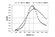
- FIG. 10A and 10B are the results of measuring the sound absorption coefficient of the sound absorbing panel 1 having the thin film 20 attached thereto and the sound absorbing panel 1′ having no thin film 20 attached thereto in the presence of the grazing flow.
- the mainstream Mach number is 0.2.
- the hole diameter of the small holes 21 of the thin film 20 was 0.17 mm
- the film thickness was 0.15 mm
- the aperture ratio was 40%, which was sufficiently larger than the aperture ratio of the holes 14.
- FIG. 10A shows the sound absorption coefficient in the same direction as the mainstream
- FIG. 10B shows the sound absorption coefficient in the opposite direction to the mainstream. From the above results, it can be seen that there are the following two features.
- the resonance frequency shift due to the grazing flow is hardly seen in the sound absorbing panel 1 to which the thin film 20 is attached. That is, the designed resonance frequency can be reproduced. Further, the resonance frequency position hardly changes even in the direction opposite to the main flow.
- the decrease in the peak sound absorption coefficient due to the Grazing flow is not seen in the sound absorbing panel 1 to which the thin film 20 is attached. That is, the sound absorbing panel 1 to which the thin film 20 is attached has an improved sound absorption rate as compared to the sound absorbing panel 1′ to which the thin film 20 is not attached. The same applies to the case of propagation in the direction opposite to the mainstream as shown in FIG. 10B.
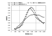
- FIGS. 11A and 11B were cases where the mainstream Mach number was 0.2, but cases where the Mach number was 0.3 are shown in FIGS. 11A and 11B. Other conditions in FIGS. 11A and 11B are similar to those in FIGS. 10A and 10B.
- the sound absorbing panel 1 to which the thin film 20 is attached has the same effect as in the case of Mach number 0.2.
- the effect of recovering the sound absorption coefficient when the thin film 20 is attached is more remarkable as the grazing flow velocity increases.
- the sound absorbing panel 1 ′ on which the thin film 20 is not attached has a sound absorption coefficient of about 0.62, whereas when the thin film 20 is attached, the sound absorption coefficient is 0.92 and the sound absorption coefficient is 50%. % Improved.
- the band having the maximum sound absorbing coefficient spreads around the resonance frequency, and as a result, the sound absorbing panel 1′ having no thin film 20 has a higher sound absorption Performance is expected.
- FIG. 12A and 12B are the results of calculating the resonance frequency and the peak sound absorption coefficient of the sound absorbing panel 1 to which the thin film 20 is attached and the sound absorbing panel 1'where the thin film 20 is not attached.
- the peak sound absorption coefficient is a sound absorption coefficient that takes a maximum value in that case although the sound absorption coefficient changes with frequency.
- FIG. 12A shows the results in the same direction as the mainstream.
- FIG. 12B is the result in the opposite direction to the mainstream.
- the results of plotting the resonance frequency (the peak frequency of the sound absorption coefficient, the resonance frequency of the static field is F0) and the peak sound absorption coefficient are shown.
- the resonance frequency increases as the Grazing flow increases, the sound absorption coefficient decreases, and the tendency is strong for sound propagation in the same direction as the main flow.
- both the frequency and the sound absorption coefficient are maintained, and the acoustic performance is maintained without deviating from the performance predicted from the panel shape design.
- FIG. 13 is a comparison result of sound absorption rates in a static field between the sound absorbing panel 1 to which the thin film 20 is attached and the sound absorbing panel 1′ to which the thin film 20 is not attached.
- the small hole 21 of the thin film 20 has a hole diameter of 0.17 mm, a film thickness of 0.10 mm, and an aperture ratio of 17%.
- the peak sound absorption coefficient is the same and the resonance frequency is almost the same as in the case where the thin film 20 is not attached.
- the sound absorption coefficient is increased in a wide band because the apparent resistance of the cell opening is increased.
- FIGS. 14A and 14B show the sound absorption rate in the state where there is a grazing flow of the sound absorbing panel 1 to which the thin film 20 is attached and the sound absorbing panel 1 ′ to which the thin film 20 is not attached (when the aperture ratio is 40% and 17%). It is a comparison result.
- FIG. 14A shows the results in the same direction as the mainstream.
- FIG. 14B is the result in the opposite direction to the mainstream.
- the mainstream Mach number is 0.2.
- the qualitative effect of the sound absorbing panel 1 with the thin film 20 attached and the aperture ratio of 17% is the same as that of the aperture ratio of 40%.
- the peak sound absorption coefficient may decrease when the thin film 20 is attached, but the peak sound absorption coefficient is lower than that when the thin film 20 is not attached. A sound absorption coefficient recovery effect is recognized.
- FIGS. 15A and 15B were cases where the mainstream Mach number was 0.2, but cases where the Mach number was 0.3 are shown in FIGS. 15A and 15B.
- the peak sound absorption coefficient in the same direction as the mainstream is lower than that in the case of 40% aperture ratio, and the peak sound absorption coefficient is in the opposite direction to the mainstream. Has decreased.
- the sound absorbing panel 1 with the thin film 20 attached and the aperture ratio of 17% the sound absorbing performance is slightly deteriorated, but a sufficient recovery effect is recognized as compared with the case where the thin film 20 is not attached.
- the sound absorbing panel 1 to which the thin film 20 is attached in particular, when the hole diameter is about 0.2 mm and the film thickness is on the order of the hole diameter, when the aperture ratio is 17 to 40%, the sound absorbing panel 1 is not attached. It can be seen that the sound absorption coefficient is improved.
- the sound absorbing holes 14 are provided on the surface, and a large number of small holes 21 are formed at least in the sound absorbing panel body 10, that is, on the surface of the existing sound absorbing panel.
- a thin film 20 having a plurality of small holes 21 formed therein is attached to a region R 14 corresponding to the hole 14 using, for example, an adhesive (not shown).
- the sound absorbing panel 1 according to the present embodiment has the following effects. (1) The sound absorbing panel 1 according to the present embodiment improves the peak sound absorbing coefficient under the condition that the Grazing flow is present.
- the sound absorbing panels 1, 1′ were measured using a special device that measures the sound absorbing coefficient in the flow field.
- An example in which the mainstream central Mach number is increased to 0.3 as the condition of the Grazing flow is shown.
- the thin film 20 As the thin film 20, a hole diameter of 0.17 mm and an aperture ratio of 17% and 40% were used. In the same direction as the mainstream, a sound absorption coefficient improving effect of 40% or more is obtained at a mainstream Mach number of 0.3.
- the sound absorbing panel 1 suppresses the turbulence of the flow generated on the surface by the holes 14 of the sound absorbing panel body 10.
- the turbulence of the flow affects the acoustic characteristics of the holes 14 of the sound absorbing panel body 10 and the cell structure 12 existing downstream thereof (flow interference).
- the thin film 20 is expected to suppress the deterioration of the sound absorbing performance due to the flow interference.
- the suppression of turbulence stabilizes the operation of a fluid machine downstream of the turbulence, for example, and contributes to the improvement of the efficiency of the entire system.
- the thin film 20 attached to the sound absorbing panel body 10 has an effect of mitigating an impact on the sound absorbing panel body 10 and avoiding laceration due to scattered objects.
- the thin film 20 has a large hydrodynamic impermeability due to the small holes 21, and suppresses mixing of dust and the like into the cell structure 12.
- the sound absorbing panel 1 can be cleaned by exchanging the thin film 20, and it is expected that the sound absorbing panel body 10 will not be removed and the engine including the duct will not be overhauled, which contributes to extending the life of the sound absorbing panel 1.
- the sound absorbing panel 1 according to the present embodiment has a basic configuration in which the thin film 20 having the small holes 21 is attached to the sound absorbing panel body 10, and can be additionally applied to an existing sound absorbing panel. The method is simple.
- the sound absorbing panel 1 according to this embodiment has an effect of preventing water droplets on the surface of the thin film 20 from penetrating into the cell structure 12. It is also possible to prevent water droplets from entering by selecting the diameter of the small holes 21 in consideration of the surface tension of the water droplets.
- the sound absorbing panel 1 may be of the following types.
- Type 1 The sound absorbing panel 1 is installed on the wall surface of the propagation path to prevent the propagation of noise.
- the propagation path is usually a duct-like flow path.
- the surface plate 11 is installed on the wall surface of the propagation path, and the cell structure 12 and the back wall 13 exist behind it.
- An air flow may exist inside the propagation path, and the air flow may have a velocity distribution or a temperature distribution in the path cross-sectional direction. Noise may propagate in the same direction as the airflow or in the opposite direction.
- the acoustic mode according to the cross-sectional shape of the route in the noise (a sound pressure distribution in which there are antinodes and nodes of the sound pressure, there are multiple sound pressure distributions at the same frequency, and the spatial distribution of the sound pressure distribution (Including changes in position over time).
- the sound absorption panel 1 installed on the inner wall of the intake duct or the exhaust duct of the jet engine for aircraft, reduce the sound pressure of the noise generated by the fan before it is emitted to the outside of the engine.
- the effect of reducing fan noise is increased.-By installing the sound absorbing panel 1 on a part of the inner wall of the combustion chamber of the gas turbine or the inner wall of the exhaust passage, the combustor or turbine To reduce the sound pressure of the sound generated in the engine before it is emitted to the outside of the engine.
- the high-speed exhaust jet after cooling is introduced to the outside of the duct to exhaust it to the outside.
- the sound absorbing panel 1 is also install the sound absorbing panel 1 on the inner wall of the duct on the air intake side to release the noise generated from the blower, compressor, etc. to the outside. Attenuating before doing so.
- the sound absorbing panel 1 is installed on the surface of a wall, a fence, or a structure placed in an open space. There may be airflow on the panel surface. The advancing direction of the incident noise does not have to be perpendicular to the panel surface plate.
- ⁇ Install the sound absorbing panel 1 on the wall surface of the room where quietness is required to suppress the echo in the room ⁇ Install the sound absorbing panel 1 on the surface of the fence on the route where the vehicle passes, and generate it from the vehicle or the road surface To reduce the noise exposure to the surroundings by weakening the reflection of noise incident on the fence.
- ⁇ Sound absorption panel on the surface of the aircraft body body surface, high lift device such as flaps, landing device such as legs and storage doors. 1 to suppress the generation of aerodynamic noise, the attenuation of boundary layer noise, the reflection of sound from other parts such as the engine, and the suppression of noise emission to the far side of the aircraft-The aircraft should be limited to aircraft. However, automobiles and railway vehicles are also assumed. In the case of an automobile, by installing the sound absorbing panel 1 in a part of the vehicle body, it is possible to suppress the generation of the peeling sound from the door mirror, the peeling sound at the rear part of the body, the boundary layer sound on the surface of the vehicle body, and the sound absorption, so that the sound can be transmitted outside and inside the vehicle.
- Noise of a railway vehicle ⁇ By installing a sound absorbing panel 1 on the surface of a railway vehicle, it is possible to suppress aerodynamic noise generated from pantographs, vehicle body gaps and steps during high-speed running, and suppress surface reflection. However, suppressing the noise to the inside and outside of the vehicle.
- the sound absorbing panel 1 is not limited to the resonance type sound absorbing panel behind the thin film according to the present invention. In addition to this, it is possible to install a porous material or a fibrous sound absorbing material.
- the sound absorbing panel 1 is installed on all or part of the boundary surface covering the closed space to reduce internal noise. It is assumed that a noise field is formed in a closed space because it includes a noise source, and a noise field that does not include a noise source but is introduced through vibration from an external noise source is formed. By installing the sound absorbing panel 1 in all or part of the closed space, the amplitude of the noise propagating in the closed space is attenuated on the panel surface, so that the noise in the closed space is reduced as compared with the case without the panel. Imagine that.
- the sound absorbing panel according to the present invention improves the noise reducing ability of a system in which noise propagates in an air flow such as an aircraft, an aircraft engine, a power generator, a prime mover, an air conditioning refrigerator, and general transportation equipment such as automobiles, railways, and aircraft.
- the present invention can be applied to, for example, improving the sound absorption performance of a surface having a mixture of airflow and noise, improving the structural strength of the noise reducing device, and improving the performance of the main body device by the noise reducing device.
- the application example is shown below.
- a thin film is installed on the surface of the sound absorbing panel on the inner wall surface of the duct.
- the small holes formed in the thin film are about 0.25 mm or less, and the aperture ratio is made larger than that of the panel holes so that a plurality of small holes exist in the panel holes.
- the perforation position in the thin film may be changed so that the small hole group is present only in the portion where the panel hole exists.
- the thin film may be installed without a gap between the thin film and the panel surface plate, or may be provided with a gap.
- a sound absorbing panel may be installed on the inner wall of the flow path (duct) that sucks in the outside air or the discharge path (duct), and the thin film according to the present invention is installed on the surface of the sound absorbing panel that is in contact with the air flow.
- High-temperature exhaust duct In the present invention having heat resistance when a metal honeycomb structure or a heat-resistant sound-absorbing material is used in a flow path through which sound emitted from a high-temperature portion such as a gas turbine or an engine propagates Providing such a thin film with small holes is expected to improve sound absorbing performance, protect the sound absorbing member from heat, and reduce loss even if the grazing flow increases.
- Application Example 4 Combustor Inside the combustor such as a ground-based gas turbine, an aeronautical gas turbine, and a rocket engine, pressure fluctuations of medium to low frequency and high amplitude occur due to combustion of high-temperature gas.
- a resonance chamber called a resonator may be provided on the wall surface of the combustor. Since the air flow also exists inside the combustor, the thin film of the present invention having heat resistance can be installed in the opening portion of the resonator to promote the relaxation of the pressure fluctuation passing through the resonator.
- the thin film with small holes of the present invention shows, while allowing pressure fluctuations such as sound to be transmitted, the flow of the fluid on the surface is not transmitted or substantially not transmitted as much as possible. Is also applicable.
- the thin film according to the present invention is attached to the blade tip surface or the structure surface. Prevents flow separation on the surface to avoid lower lift and increased resistance. By sticking the thin film having the small holes according to the present invention to the main wing and flaps of the aircraft, the surface of the leg structure, and mainly toward the (wing) end of the wind turbine blade, peeling that occurs when it is not stuck To prevent sudden drop in lift force, increase in resistance, and noise generation.
- the present invention also includes a structure in which the surface of these structures is covered with a porous material and the thin film with small holes according to the present invention is attached to the surface. For example, as shown in FIGS.
- a flow around a cylinder causes separation on the surface of the cylinder, which becomes a noise source, for example, a pillar of an aircraft landing gear (leg) or a collector pillar (pantograph) of a railway vehicle.
- the whole or part of the surface of the cylinder 50 such as a wind turbine support of a wind power generation facility, a structure that generates wind noise, or a bridge support is replaced with an absorber 51, and a thin film with small holes according to the present invention on the surface thereof. 52 is pasted.
- the absorbing material 51 is a porous material such as pumice, a honeycomb-type sound absorbing panel, a metal fiber sound absorbing material, or the like, and internally damps pressure fluctuations.
- the small holes in the thin film 52 preferably have a diameter of 0.2 to 0.25 mm or less.
- the shape is not limited to a circle.
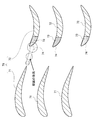
- all or part of the surface of the blade 60 is replaced with the absorber 61, and the thin film 62 with small holes according to the present invention is attached to the surface.
- the surface of a part of the wing shape (wing trailing edge, wing leading edge, wing tip, upper surface, etc.) is used as an absorbent material such as a porous material in contrast to the conventional simple wing shape (including a part of an aircraft wing).
- 61, and the thin film 62 according to the present invention is adhered to the surface of the replaced portion.
- the present invention can be applied to airfoil blades 60 of various fields.
- airfoil blades 60 of various fields.
- aircraft wings and tails high lift devices (flaps, slats), helicopter blades (main and auxiliary), wind turbine blades, jet engine fan blades, turboprop engine propellers, industrial blower fans, fans
- the present invention can be applied to fans of ventilation fans.
- sound generated on the surface or incident sound is absorbed, but the flow is not disturbed, and the generation of additional noise is suppressed.
- the idea of attaching a porous material to the surface has been studied, it is effective in reducing low frequency noise. It is generally accompanied by deterioration of aerodynamic performance and generation of high frequency noise. While maintaining the effect of the porous material, suppressing the aerodynamic performance and noise generation at high frequencies, suppressing the additional mass increase, it is possible to stick the thin film with small holes according to the present invention excellent in maintainability , Meaningful.
- a porous material is arranged on the blade leading edge surface, and the thin film with small holes according to the present invention is attached to the surface.
- a part of the front edge of the stationary blade 72 of the blade row 70 composed of the moving blade 71 and the stationary blade 72 is replaced with a pressure fluctuation absorbing material 73 such as a porous material, and the surface of the invention is The thin film 74 with small holes is attached.
- a part of the leading edge of the vane 72 is used as a pressure fluctuation absorbing material such as a porous material, as compared with the conventional simple vane shape.
- the present invention is applicable to blade rows in various fields.
- the present invention can be applied to an axial compressor of a gas turbine, an aero engine fan, an axial compressor, a blower, a support structure of a ventilation fan, an air flow splitter (deflecting device) of an exhaust silencer, and the like.
- an axial-flow rotating machine such as a compressor or a fan
- a backflow generated from a blade row in the front stage collides with a blade row in the rear stage to cause a large pressure fluctuation, which may be emitted to the outside as interference noise.
- An example of this application is interference noise between the rotor blades of a wind turbine and the support.
- the pressure field around the moving blade interferes with the support to increase the pressure fluctuation and increase the wind turbine noise.
- the thin film with small holes according to the present invention is attached to the surface of a moving object such as a body or a vehicle.
- a moving object such as a body or a vehicle.
- part or all of the surface of a moving body 80 such as a vehicle or an aircraft is replaced with a pressure fluctuation absorbing material 81 such as a porous material, and the present invention is applied to the surface.
- the thin film 82 with small holes is attached.
- a part of the surface shape is replaced with a pressure fluctuation absorbing material 81 such as a porous material in comparison with the conventional simple surface shape to absorb the pressure fluctuation of the porous material.
- the thin film 82 with small holes according to the present invention is adhered to the surface of the material 81.
- INDUSTRIAL APPLICABILITY The present invention can be applied to moving object surfaces in various fields. For example, the surface of car bodies of automobiles and large vehicles, door mirrors, doors and windows, steps, etc., railroad car doors, windows, steps between vehicles, parts in the front of the car body that undergo pressure fluctuations during tunnel entry, and more
- the present invention can be applied to the part where boundary layer noise is generated on the surface of the machine body, the part exposed to the engine, and the like. In the case of an aircraft, since a boundary layer is formed on the surface of the fuselage, it is known that boundary layer noise propagates in the passenger compartment.
- the thin film with small holes according to the present invention is attached to a suitable place on the surface of the body or the vehicle body, or the surface is used as a base for suppressing sound absorption or pressure fluctuation such as a porous material, and the surface of the present invention is related to the present invention.
- the thin film with small holes according to the present invention can be applied to an outer wall of a building, a fence, and an inner wall of a wind tunnel of special wind tunnel equipment.
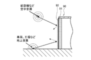
- a part or all of the structure 90 such as the outer wall of the building, the wall, and the inner wall of the wind tunnel is replaced with a pressure fluctuation absorbing material 91 such as a resonance type or porous material
- the thin film 92 with small holes according to the present invention is attached to the surface thereof.
- FIG. 20 is an example in which the present invention is applied to an outer wall of a building, a fence, etc., and FIGS.
- 21A and 21B are examples in which the present invention is applied to an inner wall of a wind tunnel.
- the surface of a structure 90 such as an outer wall of a building or a wall of a road is replaced with a pressure fluctuation absorbing material 91 such as a porous material in place of a conventional simple surface shape.
- the thin film 92 with small holes according to the present invention is brought into close contact with the surface of the pressure fluctuation absorbing material 91.
- the present invention can be applied to structure surfaces in various fields. For example, by painting the surface to bring quietness in the vicinity of the building, it is possible to visually recognize the artistic effect of the building surface, etc., to ensure sound absorption on the surface of the sound insulation wall, and to visually recognize signs on the wall.
- Kevlar film formation is sometimes used. The Kevlar film does not have sufficient sound transmission properties (low frequency sound is transmitted at a high rate, but high frequency sound is not sufficiently transmitted).
- the frame structure for fixing the thin film according to the present invention to the wall of the wind tunnel is a perforated member having a large aperture ratio.
- the thin film with small holes according to the present invention can also be applied to a windscreen.
- a windscreen When using a microphone outdoors to measure environmental noise, it is exposed to wind and rainfall. The wind affects the observation data as low frequency noise, so it is necessary to take measures to reduce the wind hitting the microphone.
- woven screens and foam screens are used, and a certain waterproof effect is expected.
- the thin film according to the present invention which is a small perforated thin film that does not transmit the flow such as wind but allows the sound to pass, to the frame of the screen, it can play the role of a windscreen.
- the frame is a perforated member having a large perforated structure.
- the present invention is not limited to the above embodiments.
- the present invention can be variously modified and applied within the scope of the technical idea thereof, and the scope of the implementation also belongs to the technical scope of the present invention.
Landscapes
- Engineering & Computer Science (AREA)
- Physics & Mathematics (AREA)
- Acoustics & Sound (AREA)
- Multimedia (AREA)
- Aviation & Aerospace Engineering (AREA)
- Mechanical Engineering (AREA)
- Soundproofing, Sound Blocking, And Sound Damping (AREA)
- Laminated Bodies (AREA)
Applications Claiming Priority (2)
| Application Number | Priority Date | Filing Date | Title |
|---|---|---|---|
| JP2018226694A JP7352925B2 (ja) | 2018-12-03 | 2018-12-03 | 圧力変動吸収構造体 |
| JP2018-226694 | 2018-12-03 |
Publications (1)
| Publication Number | Publication Date |
|---|---|
| WO2020115960A1 true WO2020115960A1 (ja) | 2020-06-11 |
Family
ID=70974931
Family Applications (1)
| Application Number | Title | Priority Date | Filing Date |
|---|---|---|---|
| PCT/JP2019/033834 Ceased WO2020115960A1 (ja) | 2018-12-03 | 2019-08-29 | 圧力変動吸収構造体及び圧力変動抑制用の薄膜 |
Country Status (2)
| Country | Link |
|---|---|
| JP (1) | JP7352925B2 (https=) |
| WO (1) | WO2020115960A1 (https=) |
Families Citing this family (2)
| Publication number | Priority date | Publication date | Assignee | Title |
|---|---|---|---|---|
| WO2022091542A1 (ja) | 2020-10-30 | 2022-05-05 | 国立研究開発法人宇宙航空研究開発機構 | 圧力変動吸収構造体 |
| WO2025023267A1 (ja) * | 2023-07-27 | 2025-01-30 | 株式会社Ihi | リブレット付き吸音パネル |
Citations (5)
| Publication number | Priority date | Publication date | Assignee | Title |
|---|---|---|---|---|
| US6182787B1 (en) * | 1999-01-12 | 2001-02-06 | General Electric Company | Rigid sandwich panel acoustic treatment |
| JP2015007791A (ja) * | 2008-04-22 | 2015-01-15 | スリーエム イノベイティブ プロパティズ カンパニー | 複合吸音シート |
| JP2016536624A (ja) * | 2013-09-25 | 2016-11-24 | パナシアン マイクロベント テック(ジアンスー)コーポレーションPanasian Microvent Tech(Jiangsu)Corporation | 交通音遮断用高吸音複合材料及びその製造方法 |
| JP2016213829A (ja) * | 2015-04-30 | 2016-12-15 | 日東電工株式会社 | 高分子樹脂フィルムとこれを備える通気膜、通音膜、音響抵抗体、通気膜部材、通音膜部材、音響抵抗体部材および音響機器ならびに高分子樹脂フィルムの製造方法 |
| JP2019028176A (ja) * | 2017-07-27 | 2019-02-21 | 富士フイルム株式会社 | 防音構造 |
Family Cites Families (1)
| Publication number | Priority date | Publication date | Assignee | Title |
|---|---|---|---|---|
| JP2003295867A (ja) | 2002-02-01 | 2003-10-15 | Ngk Insulators Ltd | 吸音構造体 |
-
2018
- 2018-12-03 JP JP2018226694A patent/JP7352925B2/ja active Active
-
2019
- 2019-08-29 WO PCT/JP2019/033834 patent/WO2020115960A1/ja not_active Ceased
Patent Citations (5)
| Publication number | Priority date | Publication date | Assignee | Title |
|---|---|---|---|---|
| US6182787B1 (en) * | 1999-01-12 | 2001-02-06 | General Electric Company | Rigid sandwich panel acoustic treatment |
| JP2015007791A (ja) * | 2008-04-22 | 2015-01-15 | スリーエム イノベイティブ プロパティズ カンパニー | 複合吸音シート |
| JP2016536624A (ja) * | 2013-09-25 | 2016-11-24 | パナシアン マイクロベント テック(ジアンスー)コーポレーションPanasian Microvent Tech(Jiangsu)Corporation | 交通音遮断用高吸音複合材料及びその製造方法 |
| JP2016213829A (ja) * | 2015-04-30 | 2016-12-15 | 日東電工株式会社 | 高分子樹脂フィルムとこれを備える通気膜、通音膜、音響抵抗体、通気膜部材、通音膜部材、音響抵抗体部材および音響機器ならびに高分子樹脂フィルムの製造方法 |
| JP2019028176A (ja) * | 2017-07-27 | 2019-02-21 | 富士フイルム株式会社 | 防音構造 |
Also Published As
| Publication number | Publication date |
|---|---|
| JP7352925B2 (ja) | 2023-09-29 |
| JP2020091324A (ja) | 2020-06-11 |
Similar Documents
| Publication | Publication Date | Title |
|---|---|---|
| Zamponi et al. | On the role of turbulence distortion on leading-edge noise reduction by means of porosity | |
| Yi et al. | Design and characterization of a multifunctional low-speed anechoic wind tunnel at HKUST | |
| US12499861B2 (en) | Pressure fluctuation absorbing structure | |
| EP1998003B1 (en) | Noise control cassette for a gas turbine engine | |
| US6851515B2 (en) | Soundproofing panel, in particular structural or lining panel for a rotorcraft | |
| US9057329B2 (en) | Turboprop engine systems with noise reducing inlet assemblies | |
| US9670878B2 (en) | Cellular acoustic structure for a turbojet engine and turbojet engine incorporating at least one such structure | |
| Angland et al. | Use of blowing flow control to reduce bluff body interaction noise | |
| Soderman et al. | Microphone measurements in and out of airstream | |
| Lawrence et al. | Installed jet-flap impingement tonal noise | |
| WO2020115960A1 (ja) | 圧力変動吸収構造体及び圧力変動抑制用の薄膜 | |
| US11472565B2 (en) | Turbomachine nacelle having acoustically porous walls | |
| von Heesen et al. | Suppression of wind tunnel buffeting by active flow control | |
| Mathew et al. | Characterization of an anechoic wind tunnel facility | |
| Duell et al. | Progress in aeroacoustic and climatic wind tunnels for automotive wind noise and acoustic testing | |
| JP2019138977A (ja) | 共鳴型吸音パネル | |
| Best et al. | Lockheed Martin Low-Speed Wind Tunnel Acoustic Upgrade | |
| Palleja-Cabre et al. | Reduction of turbulence-aerofoil interaction noise by the use of Kevlar-covered air gaps | |
| Clair et al. | Turbulence interaction noise from a rectilinear cascade of airfoils and effects of porous material inclusions | |
| Breitbach et al. | Acoustic challenges of the A400M for active systems | |
| Azam et al. | Noise abatement system in commercial aircraft by using Bias Acoustic Liner on nacelle lip-skin | |
| Mancini et al. | Towards Numerical Simulations of Noise Installation Effects for Pusher Propeller Configurations | |
| Marsh | Study of Acoustical Treatments for Jet‐Engine Nacelles | |
| Logue et al. | Passive control of fan broadband noise | |
| CN114856816B (zh) | 航空发动机降噪声衬及航空发动机 |
Legal Events
| Date | Code | Title | Description |
|---|---|---|---|
| 121 | Ep: the epo has been informed by wipo that ep was designated in this application |
Ref document number: 19893276 Country of ref document: EP Kind code of ref document: A1 |
|
| NENP | Non-entry into the national phase |
Ref country code: DE |
|
| 122 | Ep: pct application non-entry in european phase |
Ref document number: 19893276 Country of ref document: EP Kind code of ref document: A1 |