WO2020111282A1 - ガラス板の製造方法、ガラス板の面取り方法、および磁気ディスクの製造方法 - Google Patents
ガラス板の製造方法、ガラス板の面取り方法、および磁気ディスクの製造方法 Download PDFInfo
- Publication number
- WO2020111282A1 WO2020111282A1 PCT/JP2019/047102 JP2019047102W WO2020111282A1 WO 2020111282 A1 WO2020111282 A1 WO 2020111282A1 JP 2019047102 W JP2019047102 W JP 2019047102W WO 2020111282 A1 WO2020111282 A1 WO 2020111282A1
- Authority
- WO
- WIPO (PCT)
- Prior art keywords
- glass plate
- face
- laser light
- manufacturing
- disk
- Prior art date
- Legal status (The legal status is an assumption and is not a legal conclusion. Google has not performed a legal analysis and makes no representation as to the accuracy of the status listed.)
- Ceased
Links
Images


Classifications
-
- B—PERFORMING OPERATIONS; TRANSPORTING
- B23—MACHINE TOOLS; METAL-WORKING NOT OTHERWISE PROVIDED FOR
- B23K—SOLDERING OR UNSOLDERING; WELDING; CLADDING OR PLATING BY SOLDERING OR WELDING; CUTTING BY APPLYING HEAT LOCALLY, e.g. FLAME CUTTING; WORKING BY LASER BEAM
- B23K26/00—Working by laser beam, e.g. welding, cutting or boring
- B23K26/352—Working by laser beam, e.g. welding, cutting or boring for surface treatment
- B23K26/354—Working by laser beam, e.g. welding, cutting or boring for surface treatment by melting
-
- B—PERFORMING OPERATIONS; TRANSPORTING
- B23—MACHINE TOOLS; METAL-WORKING NOT OTHERWISE PROVIDED FOR
- B23K—SOLDERING OR UNSOLDERING; WELDING; CLADDING OR PLATING BY SOLDERING OR WELDING; CUTTING BY APPLYING HEAT LOCALLY, e.g. FLAME CUTTING; WORKING BY LASER BEAM
- B23K26/00—Working by laser beam, e.g. welding, cutting or boring
- B23K26/0006—Working by laser beam, e.g. welding, cutting or boring taking account of the properties of the material involved
-
- B—PERFORMING OPERATIONS; TRANSPORTING
- B23—MACHINE TOOLS; METAL-WORKING NOT OTHERWISE PROVIDED FOR
- B23K—SOLDERING OR UNSOLDERING; WELDING; CLADDING OR PLATING BY SOLDERING OR WELDING; CUTTING BY APPLYING HEAT LOCALLY, e.g. FLAME CUTTING; WORKING BY LASER BEAM
- B23K26/00—Working by laser beam, e.g. welding, cutting or boring
- B23K26/02—Positioning or observing the workpiece, e.g. with respect to the point of impact; Aligning, aiming or focusing the laser beam
- B23K26/06—Shaping the laser beam, e.g. by masks or multi-focusing
- B23K26/073—Shaping the laser spot
- B23K26/0736—Shaping the laser spot into an oval shape, e.g. elliptic shape
-
- B—PERFORMING OPERATIONS; TRANSPORTING
- B23—MACHINE TOOLS; METAL-WORKING NOT OTHERWISE PROVIDED FOR
- B23K—SOLDERING OR UNSOLDERING; WELDING; CLADDING OR PLATING BY SOLDERING OR WELDING; CUTTING BY APPLYING HEAT LOCALLY, e.g. FLAME CUTTING; WORKING BY LASER BEAM
- B23K26/00—Working by laser beam, e.g. welding, cutting or boring
- B23K26/352—Working by laser beam, e.g. welding, cutting or boring for surface treatment
- B23K26/3568—Modifying rugosity
- B23K26/3576—Diminishing rugosity, e.g. by grinding, polishing or smoothing
-
- B—PERFORMING OPERATIONS; TRANSPORTING
- B24—GRINDING; POLISHING
- B24B—MACHINES, DEVICES, OR PROCESSES FOR GRINDING OR POLISHING; DRESSING OR CONDITIONING OF ABRADING SURFACES; FEEDING OF GRINDING, POLISHING, OR LAPPING AGENTS
- B24B37/00—Lapping machines or devices; Accessories
- B24B37/04—Lapping machines or devices; Accessories designed for working plane surfaces
- B24B37/07—Lapping machines or devices; Accessories designed for working plane surfaces characterised by the movement of the work or lapping tool
- B24B37/08—Lapping machines or devices; Accessories designed for working plane surfaces characterised by the movement of the work or lapping tool for double side lapping
-
- B—PERFORMING OPERATIONS; TRANSPORTING
- B24—GRINDING; POLISHING
- B24B—MACHINES, DEVICES, OR PROCESSES FOR GRINDING OR POLISHING; DRESSING OR CONDITIONING OF ABRADING SURFACES; FEEDING OF GRINDING, POLISHING, OR LAPPING AGENTS
- B24B7/00—Machines or devices designed for grinding plane surfaces on work, including polishing plane glass surfaces; Accessories therefor
- B24B7/10—Single-purpose machines or devices
- B24B7/16—Single-purpose machines or devices for grinding end-faces, e.g. of gauges, rollers, nuts, piston rings
- B24B7/17—Single-purpose machines or devices for grinding end-faces, e.g. of gauges, rollers, nuts, piston rings for simultaneously grinding opposite and parallel end faces, e.g. double disc grinders
-
- B—PERFORMING OPERATIONS; TRANSPORTING
- B24—GRINDING; POLISHING
- B24B—MACHINES, DEVICES, OR PROCESSES FOR GRINDING OR POLISHING; DRESSING OR CONDITIONING OF ABRADING SURFACES; FEEDING OF GRINDING, POLISHING, OR LAPPING AGENTS
- B24B7/00—Machines or devices designed for grinding plane surfaces on work, including polishing plane glass surfaces; Accessories therefor
- B24B7/20—Machines or devices designed for grinding plane surfaces on work, including polishing plane glass surfaces; Accessories therefor characterised by a special design with respect to properties of the material of non-metallic articles to be ground
- B24B7/22—Machines or devices designed for grinding plane surfaces on work, including polishing plane glass surfaces; Accessories therefor characterised by a special design with respect to properties of the material of non-metallic articles to be ground for grinding inorganic material, e.g. stone, ceramics, porcelain
- B24B7/24—Machines or devices designed for grinding plane surfaces on work, including polishing plane glass surfaces; Accessories therefor characterised by a special design with respect to properties of the material of non-metallic articles to be ground for grinding inorganic material, e.g. stone, ceramics, porcelain for grinding or polishing glass
- B24B7/242—Machines or devices designed for grinding plane surfaces on work, including polishing plane glass surfaces; Accessories therefor characterised by a special design with respect to properties of the material of non-metallic articles to be ground for grinding inorganic material, e.g. stone, ceramics, porcelain for grinding or polishing glass for plate glass
-
- B—PERFORMING OPERATIONS; TRANSPORTING
- B24—GRINDING; POLISHING
- B24B—MACHINES, DEVICES, OR PROCESSES FOR GRINDING OR POLISHING; DRESSING OR CONDITIONING OF ABRADING SURFACES; FEEDING OF GRINDING, POLISHING, OR LAPPING AGENTS
- B24B9/00—Machines or devices designed for grinding edges or bevels on work or for removing burrs; Accessories therefor
- B24B9/02—Machines or devices designed for grinding edges or bevels on work or for removing burrs; Accessories therefor characterised by a special design with respect to properties of materials specific to articles to be ground
- B24B9/06—Machines or devices designed for grinding edges or bevels on work or for removing burrs; Accessories therefor characterised by a special design with respect to properties of materials specific to articles to be ground of non-metallic inorganic material, e.g. stone, ceramics, porcelain
- B24B9/08—Machines or devices designed for grinding edges or bevels on work or for removing burrs; Accessories therefor characterised by a special design with respect to properties of materials specific to articles to be ground of non-metallic inorganic material, e.g. stone, ceramics, porcelain of glass
- B24B9/10—Machines or devices designed for grinding edges or bevels on work or for removing burrs; Accessories therefor characterised by a special design with respect to properties of materials specific to articles to be ground of non-metallic inorganic material, e.g. stone, ceramics, porcelain of glass of plate glass
-
- C—CHEMISTRY; METALLURGY
- C03—GLASS; MINERAL OR SLAG WOOL
- C03B—MANUFACTURE, SHAPING, OR SUPPLEMENTARY PROCESSES
- C03B29/00—Reheating glass products for softening or fusing their surfaces; Fire-polishing; Fusing of margins
- C03B29/02—Reheating glass products for softening or fusing their surfaces; Fire-polishing; Fusing of margins in a discontinuous way
-
- C—CHEMISTRY; METALLURGY
- C03—GLASS; MINERAL OR SLAG WOOL
- C03C—CHEMICAL COMPOSITION OF GLASSES, GLAZES OR VITREOUS ENAMELS; SURFACE TREATMENT OF GLASS; SURFACE TREATMENT OF FIBRES OR FILAMENTS MADE FROM GLASS, MINERALS OR SLAGS; JOINING GLASS TO GLASS OR OTHER MATERIALS
- C03C23/00—Other surface treatment of glass not in the form of fibres or filaments
- C03C23/0005—Other surface treatment of glass not in the form of fibres or filaments by irradiation
- C03C23/0025—Other surface treatment of glass not in the form of fibres or filaments by irradiation by a laser beam
-
- G—PHYSICS
- G11—INFORMATION STORAGE
- G11B—INFORMATION STORAGE BASED ON RELATIVE MOVEMENT BETWEEN RECORD CARRIER AND TRANSDUCER
- G11B5/00—Recording by magnetisation or demagnetisation of a record carrier; Reproducing by magnetic means; Record carriers therefor
- G11B5/62—Record carriers characterised by the selection of the material
- G11B5/73—Base layers, i.e. all non-magnetic layers lying under a lowermost magnetic recording layer, e.g. including any non-magnetic layer in between a first magnetic recording layer and either an underlying substrate or a soft magnetic underlayer
-
- G—PHYSICS
- G11—INFORMATION STORAGE
- G11B—INFORMATION STORAGE BASED ON RELATIVE MOVEMENT BETWEEN RECORD CARRIER AND TRANSDUCER
- G11B5/00—Recording by magnetisation or demagnetisation of a record carrier; Reproducing by magnetic means; Record carriers therefor
- G11B5/84—Processes or apparatus specially adapted for manufacturing record carriers
-
- B—PERFORMING OPERATIONS; TRANSPORTING
- B23—MACHINE TOOLS; METAL-WORKING NOT OTHERWISE PROVIDED FOR
- B23K—SOLDERING OR UNSOLDERING; WELDING; CLADDING OR PLATING BY SOLDERING OR WELDING; CUTTING BY APPLYING HEAT LOCALLY, e.g. FLAME CUTTING; WORKING BY LASER BEAM
- B23K2103/00—Materials to be soldered, welded or cut
- B23K2103/50—Inorganic materials other than metals or composite materials
- B23K2103/54—Glass
-
- B—PERFORMING OPERATIONS; TRANSPORTING
- B23—MACHINE TOOLS; METAL-WORKING NOT OTHERWISE PROVIDED FOR
- B23K—SOLDERING OR UNSOLDERING; WELDING; CLADDING OR PLATING BY SOLDERING OR WELDING; CUTTING BY APPLYING HEAT LOCALLY, e.g. FLAME CUTTING; WORKING BY LASER BEAM
- B23K26/00—Working by laser beam, e.g. welding, cutting or boring
- B23K26/08—Devices involving relative movement between laser beam and workpiece
Definitions
- the present invention relates to a method for manufacturing a glass plate, which processes the end surface of a disk-shaped glass plate, a method for chamfering a glass plate, which forms a chamfered surface on the end surface of the disk-shaped glass plate by irradiation with laser light, and a method for manufacturing a glass plate.
- the present invention relates to a magnetic disk manufacturing method using a method or a chamfering method.
- a magnetic disk in which a magnetic layer is provided on a disk-shaped non-magnetic glass substrate for a magnetic disk is used as a hard disk device for data recording.
- the end surface of the disk-shaped glass base plate which is the final product of the glass substrate for a magnetic disk, has fine particles adhering to the main surface, which adversely affects the performance of the magnetic disk.
- Patent Document 1 a method of chamfering the edge of the glass plate using laser light is known (Patent Document 1). Specifically, an ultrashort pulse laser is used to cut an edge into a desired chamfered shape, followed by irradiation with a CO 2 laser after treatment with the ultrashort pulse laser.
- the member to be removed is separated by irradiating the CO 2 laser after cutting the edge with the ultrashort pulse laser.
- edge cutting by the ultrashort pulse laser it was not possible to process the end face of the target shape, and the shape of the end face became the target shape suitable for gripping by the jig when forming the magnetic film described above. It was difficult to become, and there were cases where there were variations. Further, since the end face shape processing is performed by using both the ultrashort laser and the CO 2 laser, the shape processing operation is complicated.
- the glass plate of the magnetic disk tends to be thinned to increase the number of magnetic disks incorporated in the HDD device in order to increase the capacity of a hard disk drive device (hereinafter referred to as HDD device).
- HDD device a hard disk drive device
- a glass material that enhances the rigidity of the glass plate is used in order to suppress the vibration of the glass plate that is likely to occur when the glass substrate becomes thin. Since a glass material having high rigidity generally has a high softening point, it is difficult to shape the laser light.
- the laser light irradiation condition is conventionally set. It is necessary to make detailed settings compared to.
- An object of the present invention is to provide a method for manufacturing a glass plate and a method for manufacturing a magnetic disk, which can be manufactured.
- One aspect of the present invention is a method for manufacturing a glass plate, which includes shaping an end surface of a disk-shaped glass plate.
- the disk-shaped glass plate has a main surface and an end face perpendicular to the main surface.
- the manufacturing method is Irradiating the end face with a laser beam, while moving the laser beam relative to the end face in the circumferential direction of the disk-shaped glass plate, the step of processing the end face into a target shape,
- the cross-sectional intensity distribution of the laser light with which the end face is irradiated is a single mode, and the width of the light flux of the laser light at the irradiation position on the end face in the thickness direction of the glass plate is W1 [mm], and the glass is When the thickness of the plate is Th [mm] and the power density of the laser light is Pd, W1>Th, and Pd ⁇ Th is 0.8 to 3.5 [W/mm].
- Another aspect of the present invention is a method for manufacturing a glass plate, which includes processing the end surface of a disk-shaped glass plate.
- the disk-shaped glass plate has a main surface and an end face perpendicular to the main surface.
- the manufacturing method is Irradiating the end face with a laser beam, while moving the laser beam relative to the end face in the circumferential direction of the disk-shaped glass plate, a chamfered surface is formed on the end face to form a target shape.
- the cross-sectional intensity distribution of the laser light with which the end face is irradiated is a single mode, and the width of the light flux of the laser light at the irradiation position on the end face in the thickness direction of the glass plate is W1 [mm], and the glass is When the thickness of the plate is Th [mm] and the power density of the laser light is Pd, W1>Th, Pd ⁇ Th is x, and the moving speed of the laser light moving along the end face is When y is set, the value of Pd ⁇ Th and the value of the moving speed are adjusted so that y falls within the range of 11.2 ⁇ x ⁇ 4.7 or less.
- the laser light is applied to the end surface of the glass plate from a direction normal to the end surface.
- the irradiation condition of the laser light is set so as to form
- the irradiation conditions are set such that a ratio (C/Th) of the length C of the chamfered surface along the main surface to the thickness Th is 0.1 to 0.7. preferable.
- the surface roughness Rz of the end face formed by the laser beam is preferably 0.3 ⁇ m or less, and the arithmetic average roughness Ra is preferably 0.03 ⁇ m or less.
- the light flux of the laser light with which the end face is irradiated has an elliptical shape, and the ratio of the length W2 of the light flux of the laser light with which the end face is irradiated in the circumferential direction to the diameter D of the glass plate (W2/ D) is preferably 0.03 to 0.3.
- the power density Pd is set so that the diameter of the glass plate formed by the irradiation of the laser light is larger than the diameter of the glass plate before the irradiation of the laser light.
- the moving speed of the laser light that moves along the end face is preferably 0.7 to 100 [mm/sec].
- the Young's modulus of the glass plate is preferably 70 [GPa] or more.
- the glass plate has a linear expansion coefficient of 100 ⁇ 10 ⁇ 7 [1/K] or less.
- the thickness Th is preferably 0.7 mm or less.
- the method for manufacturing the glass plate includes a step of grinding or polishing the main surface of the glass plate that has been subjected to the shape processing, After the shaping, before the main surface is ground or polished, the end face is not polished, or even if the end face is polished, the removal amount by polishing the end face is 5 ⁇ m or less. Is preferred.
- Another embodiment of the present invention is a glass plate chamfering method in which a chamfered surface is formed on an end surface of a disk-shaped glass plate by irradiation with laser light.
- the end surface of the glass plate before the formation of the chamfer has a surface perpendicular to the main surface at least at the center of the glass plate in the thickness direction.
- the chamfering method is By softening and/or melting the edge portion of the end surface of the glass plate by irradiating the end surface of the glass plate with a laser beam, the edge part is chamfered into a rounded shape, and the chamfered surface of the chamfered surface.
- the thickness of the glass plate is set to Th [mm]
- the power density of the laser beam is set to Pd
- the laser beam is set to Pd so that a surface perpendicular to the main surface of the glass plate is formed also on the end face after formation.
- Yet another aspect of the present invention is a method for manufacturing a glass plate, which is characterized in that the chamfering method is used to chamfer the end face of a disk-shaped glass plate.
- Yet another aspect of the present invention is a method for producing a magnetic disk, which comprises forming a magnetic film on the main surface of the glass sheet produced by the method for producing a glass sheet.
- Another aspect of the present invention is a method for producing a magnetic disk, which comprises forming a magnetic film on the main surface of the glass sheet produced by the method for producing a glass sheet.
- the end surface of a disk-shaped glass plate is processed by using a laser beam, the end surface does not vary from the target shape, and the end surface can be easily processed by a simple operation. Shape processing can be performed.
- FIG. 1 is a diagram for explaining the irradiation of laser light in the method for manufacturing a glass plate according to one embodiment.
- FIG. 2 is a diagram illustrating an example of the shape of a light beam (spot) at the laser light irradiation position.
- FIG. 3 is a diagram for explaining the luminous flux and the light intensity distribution at the irradiation position of the laser light.
- FIG. 4 is a diagram for explaining the shape of the end face after the shape processing by the laser light.
- the glass plate to be shape-processed by the method for manufacturing a glass plate of the present embodiment is a disc shape, and a circular hole is formed at the center position of the disc shape so that an outer peripheral end and a concentric inner peripheral end are formed. It has a curved shape. From this glass plate, in order to produce a glass plate whose end face is aligned with a target shape, or so that the connecting portion between the end face of the glass plate and the main surface does not form an angular edge portion, the glass plate is Shape processing for forming a chamfer is applied to the connection portion between the main surface and the end surface.
- the shape of the end surface of the disk-shaped glass plate which is the base of the glass substrate for a magnetic disk that is the final product, makes the magnetic disk an accurate HDD device. It is desirable to make the target shape uniform in order to be incorporated in the above, and moreover, in order to surely hold the end surface of the glass substrate with a jig when forming the magnetic film on the main surface of the glass substrate. Further, in order to prevent fine particles from adhering to the main surface and adversely affecting the performance of the magnetic disk, it is desirable to smooth the surface of the end face where particles are likely to occur. For this reason, in the present embodiment, laser light is used to perform shape processing for chamfering.
- a disk-shaped glass plate 10 having a circular hole 16 has a main surface 12 and an end surface 14.
- the end surface 14 is an end surface perpendicular to the main surface 12.
- the outer peripheral end surface is the end surface 14 that is shaped by the laser light, but the inner peripheral end surface along the circular hole 16 can also be the target for shape processing by the laser light.
- the end face 14 is irradiated with laser light, and the end face 14 is processed into a target shape while moving the laser light L in the circumferential direction of the disk-shaped glass plate 10 relative to the end face 14.
- the laser light L is expanded after the laser light L emitted from a laser light source 20 described later is made into parallel light through an optical system 22 including a collimator and the like, and then the laser light L is focused through a focusing lens 24.
- the end face 14 is irradiated with the laser light L.
- the glass plate 10 is rotated at a constant speed with the center position of the glass plate 10 as the center of rotation. In this way, the laser light L and the end surface 14 are moved relative to each other in the circumferential direction of the disk-shaped glass plate 10, while the laser light L irradiates the entire circumference of the end surface 14 of the glass plate 10.
- Irradiation of the end face 14 with the laser beam L includes not only the complete normal direction (inclination angle of 0 degree) but also the range of an inclination angle within 10 degrees with respect to the normal direction as an allowable range.
- the cross-sectional intensity distribution of the laser light L with which the end face 14 is irradiated is a single mode. That is, the cross-sectional intensity distribution of the laser light L is a Gaussian distribution.
- the width in the thickness direction of the glass plate 10 of the light flux of the laser light L on the irradiation position on the end face 14 is W1 [mm] as shown in FIG. 2, and the thickness of the glass plate 10 is Th [mm].
- the power density of the laser light L is Pd [W/mm 2 ]
- Pd ⁇ Th is 0.8 to 3.5 [W/ mm] is used.
- the light flux of the laser light L is applied so as to protrude to both sides of the glass plate 10 in the thickness direction as shown in FIG. Further, by making the widths protruding to both sides of the end face equal, chamfering can be performed uniformly on both sides of the glass plate 10 in the thickness direction, and the shapes of the two chamfered faces 14c can be made equal.
- the power density Pd is a value obtained by dividing the total power P[W] of the laser light L by the area of the light flux in the portion irradiated with the laser light L.
- the power density Pd is 4 ⁇ P/W1/W2/ It is defined as ⁇ [W/mm 2 ] ( ⁇ is the circular constant).
- CO 2 laser light is used as an example of the laser light L, but it is not limited to CO 2 laser light as long as it has an oscillation wavelength that is absorbed by glass.
- a CO laser oscillation wavelength of about 5 ⁇ m or 10.6 ⁇ m
- an Er—YAG laser oscillation wavelength of about 2.94 ⁇ m
- the wavelength is preferably 3 ⁇ m or more.
- the wavelength is shorter than 3 ⁇ m, it becomes difficult for the glass to absorb the laser light, and the end face 14 of the glass plate 10 may not be sufficiently heated.
- the oscillation mode of the laser light source 20 is not particularly limited, and may be continuous wave light (CW light), pulsed light, or modulated light of continuous wave light.
- CW light continuous wave light
- the modulated light of the pulsed light and the continuous wave light when the relative moving speed of the laser light L is high, the chamfered surface 14c may have uneven shape in the moving direction.
- the frequency of oscillation and modulation is preferably 1 kHz or higher, more preferably 5 kHz or higher, and further preferably 10 kHz or higher.
- the width W1 of the light flux and the length W2 to be described later can be set by adjusting the irradiation position of the laser light L on the glass plate 10 using, for example, two cylindrical lenses.
- the width W1 can be obtained from the beam profiler, and the length W2 can be obtained from the beam shape obtained by the beam profiler and the diameter D of the glass plate.
- the side end of the end face 14 on the main surface 12 side can be sufficiently irradiated with the laser light L, and the glass plate 10 is heated.
- a chamfered surface can be formed by softening and/or melting a part of 10. If the ratio Th/W1 of the width W1 of the laser light L to the thickness of the glass plate 10 is made too large (that is, Th/W1 is too close to 1), the influence of the steep range of the laser intensity distribution is affected. As a result, the heating of the edge portion of the glass plate 10 becomes weaker, and the heating of the central portion of the end face of the glass plate in the thickness direction becomes stronger.
- Th/W1 is preferably in the range of 0.3 to 0.9.
- the power density Pd of the laser light L is excessively low, the end surface 14 is not sufficiently heated and the chamfered surface is not formed.
- the shape of the end surface 14 of the glass plate 10 can be made uniform without deviation from the target shape, and a chamfered surface can be formed. Moreover, the surface of the end face 14 can be made smooth.
- the chamfered surface 14c can be formed by limiting the range of the value of Pd ⁇ Th, but the end surface 14 is irradiated with the laser beam L by controlling the value of Pd ⁇ Th and the value of the moving speed. By doing so, the chamfered surface 14c can be efficiently formed on the end surface 14 of the glass plate 10. Further, by controlling the value of Pd ⁇ Th and the value of the moving speed in more detail, not only the chamfered surface 14c but also the surface perpendicular to the main surface 12 of the glass plate 10, that is, the side wall surface 14t can be formed. .. As a result, the shape of the end surface 14 can be made uniform with respect to the target shape.
- the surface of the end face 14 can be made smooth.
- the end surface 14 of the glass plate 10 before the chamfered surface 14c is formed has a surface perpendicular to the main surface 12 at least in the central portion in the thickness direction of the glass plate 10.
- the edge portion of the end face 14 is chamfered into a rounded shape, and the chamfered end face 14 is sandwiched between the chamfered faces 14c on both sides in the thickness direction of the glass plate 10.
- a surface (side wall surface 14t) perpendicular to the surface 12 can be formed.
- the end surface 14 preferably includes a surface perpendicular to the main surface 12 and having a length equal to or greater than 1/10 of the thickness Th, and a chamfered surface 14c.
- the length T (see FIG. 4) of the vertical surface (side wall surface 14t) is more preferably 1 ⁇ 5 or more of the thickness Th.
- the perpendicular surface formed together with the chamfered surface 14c by the irradiation of the laser beam L is perpendicular to the main surface 12 of the end surface 14 before the chamfered surface 14c is formed by the irradiation of the laser beam L.
- the surface is a newly formed surface, and the surface roughness Rz and the arithmetic average roughness Ra are reduced by the irradiation of the laser light L. Further, the radial distance from the central position of the disk-shaped glass plate 10 to the vertical surface becomes large.
- the surface perpendicular to the main surface 12 is a surface having an allowable range of 90° ⁇ 2° with respect to the main surface 12.
- forming the surface (side wall surface 14t) perpendicular to the vertical main surface 12 in addition to the chamfered surface 14c on the end surface 14 means that the outer diameter (diameter) or the inner diameter of the glass plate 10 on which the chamfered surface 14c is formed.
- the (diameter of the circular hole 16) is preferable because it can suppress variation within one glass plate 10 or between the glass plates 10. For example, if the outer diameter varies, when a plurality of glass plates 10 are incorporated into an HDD device as substrates for magnetic disks and rotated, the air flow is likely to be disturbed, which may increase troubles such as head crash.
- the shape of the chamfered surface 14c can be variously changed by controlling the value of Pd ⁇ Th and the value of the moving speed. That is, when the laser light L is emitted when at least the central portion in the thickness direction of the end face 14 of the glass plate 10 before the laser light L is irradiated is a face (side wall face 14t) perpendicular to the main surface 12. It was found that the chamfered surface 14c was formed and the surface (side wall surface 14t) perpendicular to the main surface 12 was formed by adjusting the condition of. Although this mechanism is not always clear, between the condition that the chamfering of the end face 14 does not proceed (see FIG.
- the end face 14 It is assumed that there is a condition that a vertical surface of is formed, and this condition can be selected by appropriately adjusting Pd ⁇ Th and the moving speed. That is, for example, when the value of the moving speed is kept constant and the value of Pd ⁇ Th is increased, the formation of the chamfered surface 14c starts from the edge portion, gradually progresses to the center in the thickness direction, and finally reaches the center. It is assumed that the rounding of the end surface 14 progresses in the order that the entire end surface 14 becomes round.
- the length T in the thickness direction of the vertical surface (side wall surface 14t) of the end surface 14 gradually decreases as the rounding progresses.
- a method for manufacturing a glass plate including such shape processing of the glass plate 10 will be described below using a method for manufacturing a glass substrate for a magnetic disk.
- the magnetic disk glass substrate is also a disk-shaped thin glass substrate provided with circular holes, like the glass plate 10 shown in FIG.
- the size of the glass substrate for a magnetic disk is not limited, but the glass substrate for a magnetic disk is, for example, the size of a glass substrate for a magnetic disk having a nominal diameter of 2.5 inches or 3.5 inches. In the case of a glass substrate for a magnetic disk having a nominal diameter of 3.5 inches, for example, the outer diameter (nominal value) is 95 mm to 97 mm. In the case of a glass substrate for a magnetic disk having a nominal diameter of 2.5 inches, the outer diameter (nominal value) is, for example, 65 mm to 67 mm.
- the glass substrate for a magnetic disk has a thickness of, for example, 0.20 mm to 0.65 mm, preferably 0.30 mm to 0.53 mm. A magnetic layer is formed on the main surface of this glass substrate to form a magnetic disk.
- the glass substrate has a pair of main surfaces 12 and 12, side wall surfaces 14t formed on the end surface 14 of the outer peripheral end, the side wall surface 14t and the main surfaces 12 and 12, similarly to the outer peripheral end portion of the glass plate 10 shown in FIG.
- the chamfered surfaces 14c, 14c interposed between the inner peripheral end portions and the end surfaces of the inner peripheral end portions, as well as the end surface 14 of the outer peripheral end portions, between the side wall surfaces not shown and between the side wall surfaces and the main surfaces 12, 12. And an intervening chamfer (not shown).
- the side wall surface 14t is a surface extending in a direction substantially orthogonal to the main surface 12.
- substantially orthogonal means that the inclination angle of the sidewall surface 14t with respect to the main surface 12 is in the range of 88 degrees to 92 degrees.
- the length of the side wall surface 14t shown in FIG. 4 along the thickness direction is T [mm].
- the chamfered surface 14c is smoothly connected to the main surface 14 and extends toward the side wall surface 14t.
- the chamfered surface 14c has a curved shape convex toward the outside and is smoothly connected to the side wall surface 14t. Therefore, the length C [mm] of the chamfered surface 14c shown in FIG. 4 along the main surface 12 is the length of a portion inclined with respect to the main surface 12 within a range of an inclination angle of more than 2 degrees and less than 88 degrees.
- the distance in the main surface 12 direction from the thickest position to the extreme end in the thickness direction of the glass plate 10 is The length C of the chamfered surface 14c was set.
- a glass blank slightly larger than the size of the glass plate 10 can be cut out from a large glass plate prepared in advance by using laser light.
- the large sheet glass before cutting out the glass blank is, for example, a glass plate having a constant plate thickness produced by the floating method or the downdraw method.
- it may be a glass plate obtained by press-molding a lump of glass using a mold.
- the plate thickness of the glass plate is thicker than the target plate thickness when the final product is the glass substrate for the magnetic disk by the amount of machining allowance for grinding and polishing, for example, about several ⁇ m to several hundred ⁇ m.
- a notch line is formed on a glass plate using a scriber as in the conventional method, and cracks are generated along the notch line by heating etc. You may use the method.
- the glass blank may be cut out by wet etching using an etching solution such as hydrofluoric acid.
- the wavelength of the laser light is, for example, in the range of 1030 nm to 1070 nm.
- the laser light is, for example, a pulse laser and has a pulse width of 10 ⁇ 10 ⁇ 12 seconds or less (10 picoseconds or less).
- the light energy of the laser light can be appropriately adjusted according to the pulse width and the repetition frequency of the pulse width.
- the outer portion of the outer portion and the inner portion of the defective glass plate with the boundary line as a boundary, as compared with the inner portion, or by heating the outer portion. , Separate the outer and inner parts of the glass plate.
- another kind of laser light may be irradiated along the boundary line so that the defects formed discretely along the boundary line to be cut are linearly continuous by the irradiation with the laser light.
- a CO 2 laser can be used as another type of laser light. With this laser light, linear defects can be formed so as to connect the defects formed intermittently.
- the glass plate Separate the outer and inner parts of the. In this way, a disk-shaped glass blank can be cut out from the sheet glass.
- the surface roughness Rz of the end face of the disk-shaped glass blank thus formed is, for example, 1 to 10 ⁇ m, and the arithmetic mean roughness Ra is, for example, 0.1 to 1 ⁇ m.
- a circular hole is formed by irradiation with laser light, using a scriber, or by etching.
- a glass blank having a circular hole serves as a glass base plate for producing a glass substrate for a magnetic disk.
- the end surface 14 of the glass plate 10 (glass base plate) is irradiated with the laser light L, preferably from the normal direction of the end surface 14, and the end surface 14 and the laser light L are combined.
- the shape of the end face 14 is processed into a target shape while relatively moving in the circumferential direction of the disk-shaped glass plate 10.
- the laser light L is a laser light having a single-mode cross-sectional intensity distribution, and the irradiation conditions of the laser light L are width W1>thickness Th and Pd ⁇ Th is 0.8 to 3.5 [W /Mm].
- the shape of the end surface 14 of the glass plate 10 can be made uniform with respect to the target shape, and the chamfered surface 14c can be formed. Further, by irradiating the end face 14 of the glass plate 10 before chamfering, which has a face perpendicular to the main surface 12 at least in the center in the thickness direction, with the laser light L, the edge portion of the end face 14 of the glass plate 10 is removed.
- the chamfered end surface 14 In order to chamfer the edge portion of the end surface 14 by softening and/or melting so as to have a rounded shape, further chamfering, and the chamfered end surface 14 also has a main surface of the glass plate 10.
- the value of Pd ⁇ Th and the value of moving speed are controlled, and the end surface 14 is irradiated with laser light.
- the shape of the end surface 14 of the glass plate 10 can be made uniform without varying with respect to the target shape, and the surface perpendicular to the main surface 12 and the chamfered surface 14c can be formed.
- W1>Th Pd ⁇ Th is x
- the moving speed of the laser light L moving along the end face 14 is y.
- the value of Pd ⁇ Th and the value of the moving speed are adjusted so that y falls within the range of 11.2 ⁇ x ⁇ 4.7 or less.
- W1>Th in order for the end surface 14 to have the side wall surface 14t that is a surface perpendicular to the main surface 12 in addition to the chamfered surface 14c.
- Pd ⁇ Th is x and the moving speed of the laser beam L moving along the end face 14 is y
- y is 11.2 ⁇ x ⁇ 4.7 or less and 5.4 ⁇ x ⁇ 4.
- the value of Pd ⁇ Th and the value of the moving speed are adjusted to be within the range of 0.5 or more.
- FIGS. 5A to 5C are views for explaining the difference in the shape of the end face 14 due to the difference in the irradiation condition of the laser light L. 5A to 5C, among the irradiation conditions, the thickness Th is 0.7 mm, the width W1 is 1.0 mm, the ratio Th/W1 is fixed at 0.7, and the length W2 is 10 mm.
- An example of the shape of the end face 14 when the moving speed at the position is fixed to 2 mm/sec and the power density Pd is changed to change Pd ⁇ Th is shown.
- As the glass base plate before processing one having a glass transition temperature Tg of 500° C., a diameter of 95 mm, and an end face perpendicular to the main surface was used.
- the surface roughness Rz of the end face 14 was 5 ⁇ m, and the arithmetic average roughness Ra was 0.5 ⁇ m.
- the laser light L was applied to the outer peripheral end surface of the glass base plate.
- the chamfered surface 14c is formed longer than (the length between the main surfaces), it is a shape that is not preferable as a glass substrate having a constant thickness.
- the irradiation condition by the laser light L is that, in the end face 14, the sidewall surface 14t orthogonal to the main surface 12, the chamfered surface 14c connecting the ends on both sides of the sidewall surface 14t, and the end of the main surface 12,
- the irradiation conditions are preferably set so as to form
- the range of the power density Pd is preferably set to 1.2 [W/mm 2 ] to 3.0 [W/mm 2 ].
- the irradiation condition Pd ⁇ is set so that the ratio (C/Th) of the length C along the main surface 14 of the chamfered surface 14c to the thickness Th is 0.1 to 0.7. It is preferable that Th and moving speed are set. By setting the ratio (C/Th) to 0.1 to 0.7, the function of the chamfered surface 14c having no corner at the connection portion between the end surface 14 and the main surface 12 can be exerted. Further, when the ratio (C/Th) is less than 0.1, the chamfered surface 14c is not sufficiently formed, and edges may be easily formed in a later film forming step or the like. If the ratio (C/Th) exceeds 0.7, the data recording area on the main surface 14 may be reduced.
- the ratio (C/Th) can be adjusted by adjusting the value of Th and the value of moving speed.
- the ratio (C/Th) is more preferably 0.25 to 0.5.
- irradiation is performed so that the ratio (T/Th) of the length T [mm] of the side wall surface 14t along the thickness direction to the thickness Th is 0.1 to 0.8. It is preferable to set the conditions. If the ratio (T/Th) is less than 0.1, the formation of the side wall surface 14t becomes insufficient, and it becomes difficult to measure the outer diameter or the inner diameter of the glass plate 10.
- the surface roughness Rz (JIS B0601:2001) of the end surface 14 (chamfered surface 14c, side wall surface 14t) formed by the laser beam L is preferably 0.3 ⁇ m or less, and more preferably. Is 0.2 ⁇ m or less, and the arithmetic average roughness Ra (JIS B0601:2001) is preferably 0.03 ⁇ m or less, and more preferably 0.02 ⁇ m or less.
- the surface roughness Rz and the arithmetic mean roughness Ra can be measured by, for example, a laser type optical microscope.
- the chamfered surface 14c and the side wall surface 14t can be made smooth.
- the direction of the disk-shaped circumferential direction of the glass plate 10 is changed.
- the length W2 see FIG. 2
- the temperature of the end face 14 due to heating by the laser light L is gradually increased, and the laser light L is used so that the temperature becomes the maximum at the circumferential center point of the irradiation position. It is preferable to effectively heat the end surface 14. By doing so, the moving speed at the irradiation position of the laser light L can be increased, so that the processing time can be shortened.
- the light flux of the laser light L with which the end face 14 is irradiated has an elliptical shape as shown in FIG.
- the ratio (W2/D) of the luminous flux of the laser light L with which the end face 14 is irradiated to the diameter D of the glass plate 10 in the circumferential direction W2 of the disk shape of the glass plate 10 is 0.03 to 0. It is preferably 0.3.
- the ratio (W2/D) is less than 0.03, the length W2 becomes relatively short, so that the temperature of the end surface 14 cannot be sufficiently increased and it is difficult to shorten the processing time.
- the length W2 becomes relatively long with respect to the circumferential length of the glass plate 10 in the circumferential direction.
- the irradiation position (the position in the irradiation direction of the laser light L) that irradiates the end face 14 largely changes due to the curvature of the glass plate 10, and as a result, the light flux spreads, which makes it difficult to perform efficient heating in the circumferential direction. Further, by irradiating the end face 14 of the glass plate 10 with laser light, the edge part of the end face 14 of the glass plate 10 is softened and/or melted, and the edge part of the end face 14 is chamfered into a rounded shape.
- the value of Pd ⁇ Th and the value of the moving speed are controlled to the end surface 14.
- the ratio (W2/D) is preferably 0.03 to 0.3 for the above reason.
- the diameter D of the glass plate 10 increases by several tens ⁇ m to several hundreds ⁇ m due to the rounded shape of the end face 14, and the power is further increased.
- the density Pd is increased, the rounding range is expanded and the length in the thickness direction is expanded to form a spherical shape, which reduces the diameter D of the glass plate 10. That is, the diameter D of the glass plate 10 after the shape processing changes depending on the magnitude of the power density Pd.
- the power density Pd becomes excessively large and the end face 14 is excessively heated to have a spherical shape, so that the diameter of the glass plate 10 is shortened.
- the glass plate 10 as shown in FIG. 5C is not preferable because the outer diameter is smaller than the target diameter of the glass plate 10.
- excessive heating of the end surface 14 also tends to cause variations in the spherical shape, and the diameters of the glass plate 10 cannot be made uniform, which is not preferable. Therefore, it is preferable that the power density Pd is set such that the diameter of the glass plate 10 formed by the irradiation of the laser light L is larger than the diameter of the glass plate 10 before the irradiation of the laser light L.
- the moving speed of the laser light L moving along the end surface 14 is preferably 0.7 to 100 [mm/sec].
- the moving speed is a moving speed relative to the end surface 14. From the viewpoint of processing efficiency, it is preferable that the shape processing with the laser light L is completed when the laser light L rotates around the glass plate 10 once.
- the moving speed exceeds 100 [mm/sec]
- it is difficult to complete the processing at a timing and it may be difficult to match the processing start point and the processing end point.
- the moving speed is lower than 0.7 [mm/sec]
- the shape of the end face changes due to a slight change in Pd ⁇ Th, and it becomes difficult to control the end face shape.
- the moving speed is preferably 0.7 to 100 [mm/sec].
- the moving speed is more preferably 20 to 100 [mm/sec].
- the moving speed is 20 [mm/sec] or more, the change in the shape of the end face 14 with respect to the change in Pd ⁇ Th becomes relatively gentle, and the productivity is improved by shortening the processing time. Therefore, the moving speed is more preferably 20 to 100 [mm/sec].
- the temperature of the glass plate 10 in order to promote the formation of the chamfer by the laser light L, it is preferable to set the temperature of the glass plate 10 to a temperature higher than room temperature during the shape processing of the chamfer by the laser light L. At this time, it is preferably Tg ⁇ 50° C. (Tg is the glass transition temperature of the glass plate 10) or less. Further, it is more preferable that the temperature of the glass plate 10 when the chamfering is performed be in the range of 150 to 400°C. If the temperature of the glass plate 10 is lower than 150° C., the chamfered surface 14c may not be sufficiently formed.
- the glass plate 10 When the temperature of the glass plate 10 is higher than 400° C., the glass plate 10 may be deformed and it may be difficult to irradiate the end face 14 with the laser light L.
- the glass plate 10 As a method of heating the glass plate 10, for example, the glass plate 10 may be heated before performing the chamfering process, or the glass plate 10 may be heated while performing the chamfering process.
- the glass plate 100 when the glass plate 100 is heated while the chamfering process is performed, temperature control becomes difficult due to the synergistic effect with the heating by the laser light L, and thus the variation in the shape of the end surface 14 may increase. Therefore, when heating the glass plate 10, it is preferable to heat the glass plate 10 before chamfering. In this case, it is preferable that the glass plate 10 is appropriately kept warm during the chamfering process.
- the end surface of the inner peripheral end portion is also shaped by the laser light L, and then the glass plate 10 is subjected to various treatments so as to have characteristics suitable for the final product. Is done.
- the end surface polishing processing is performed on the end surface 14 that has been shaped.
- the surface roughness Rz of the chamfered surface 14c and the side wall surface 14t can be set to 0.3 ⁇ m or less. Therefore, the removal amount in the end surface polishing process is the same as that of the conventional chamfered surface 14c using a grindstone. It can be reduced as compared with the case of processing, and production cost and production efficiency can be improved. In one embodiment, no edge polishing treatment may be performed.
- the main surface 12 of the glass plate 10 is ground by using the glass plate 10 as an intermediate glass plate before becoming the glass substrate for a magnetic disk.
- a polishing process is performed.
- the glass plate 10 is ground and then polished.
- the main surface 12 of the glass plate 10 is ground using a double-side grinding machine equipped with a planetary gear mechanism. Specifically, the main surfaces on both sides of the glass plate 10 are ground while the glass plate 10 is held in the holding holes provided in the holding member of the double-sided grinding device.
- the double-sided grinding device has a pair of upper and lower surface plates (upper surface plate and lower surface plate), and the glass plate 10 is sandwiched between the upper surface plate and the lower surface plate. Then, either or both of the upper surface plate and the lower surface plate are moved and operated, and the glass plate 10 and each surface plate are relatively moved while supplying the coolant, so that both main surfaces of the glass plate 10 are moved. Can be ground. For example, it is possible to carry out a grinding treatment by mounting a grinding member in which fixed abrasive grains, in which diamond is fixed with a resin, formed into a sheet shape, on a surface plate.
- the main surface of the glass plate 10 after grinding is subjected to first polishing. Specifically, the main surfaces on both sides of the glass plate 10 are polished while holding the glass plate 10 in the holding holes provided in the polishing carrier of the double-sided polishing apparatus.
- the purpose of the first polishing is to remove the scratches and strains remaining on the main surface after the grinding treatment, or to adjust the fine surface irregularities (micro waviness, roughness).
- the glass plate 10 is polished while applying polishing slurry by using a double-sided polishing device having the same configuration as the double-sided polishing device used for the above-described grinding process with fixed abrasive grains.
- a polishing slurry containing loose abrasive grains is used.
- the loose abrasive grains used for the first polishing for example, abrasive grains such as cerium oxide or zirconia are used.
- the double-sided polishing device as in the double-sided polishing device, the glass plate 10 is sandwiched between the pair of upper and lower surface plates.
- a ring-shaped flat plate polishing pad (for example, a resin polisher) is attached to the upper surface of the lower surface plate and the bottom surface of the upper surface plate as a whole. Then, by moving either or both of the upper surface plate and the lower surface plate, the glass plate 10 and each surface plate are relatively moved to polish both main surfaces of the glass plate 10. ..
- the size of the abrasive grains is preferably in the range of 0.5 to 3 ⁇ m in terms of average particle size (d50).
- the glass plate 10 may be chemically strengthened.
- a mixed melt of potassium nitrate and sodium nitrate is used as the chemical strengthening liquid, and the glass plate 10 is immersed in the chemical strengthening liquid.
- a compressive stress layer can be formed on the surface of the glass plate 10 by ion exchange.
- the second polishing treatment aims at mirror polishing of the main surface.
- a double-sided polishing apparatus having the same configuration as the double-sided polishing apparatus used in the first polishing is used. Specifically, while holding the glass plate 10 in the holding holes provided in the polishing carrier of the double-sided polishing device, the main surfaces on both sides of the glass plate 10 are polished.
- the second polishing process differs from the first polishing process in the type and particle size of the loose abrasive grains and the hardness of the resin polisher.
- the hardness of the resin polisher is preferably smaller than that during the first polishing process.
- a polishing liquid containing colloidal silica as free abrasive grains is supplied between the polishing pad of the double-side polishing machine and the main surface of the glass plate 10 to polish the main surface of the glass plate 10.
- the size of the abrasive grains used for the second polishing is preferably in the range of 5 to 50 nm in terms of average particle size (d50).
- the necessity of the chemical strengthening treatment may be appropriately selected in consideration of the glass composition and the necessity.
- another polishing process may be added, and the two main surfaces may be polished by one polishing process. Further, the order of the above processes may be appropriately changed.
- the main surface of the glass plate 10 can be polished to obtain a magnetic disk glass substrate that satisfies the conditions required for the magnetic disk glass plate 10. After that, at least a magnetic layer is formed on the glass plate 10 produced by polishing the main surface to produce a magnetic disk.
- the main surface 12 of the glass plate 10 that has undergone the shape processing is ground or polished.
- the end face 14 is not polished, or even if the end face 14 is polished, the removal amount by polishing the end face 14 is 5 ⁇ m. It can be: Therefore, the change in the outer diameter of the glass plate 10 can be 10 ⁇ m or less. This is because the chamfered surface 14c and the sidewall surface 14t with small surface irregularities can be formed by the laser light L.
- the magnetic disks often come into contact with the adjacent magnetic disks, and the magnetic disk located at the top of the plurality of magnetic disks arranged at regular intervals is the hard disk. In some cases, it may come into contact with the ceiling surface of the magnetic disk storage container of the drive device. In such contact, a part of the magnetic disk may be chipped to generate particles. Therefore, it is not preferable that the glass substrate for a magnetic disk has low rigidity.
- the Young's modulus of the glass plate 10 is preferably 70 [GPa] or more, more preferably 80 [GPa] or more, and more preferably 90 [GPa] or more. It is even more preferred to be present.
- the thickness Th of the glass plate 10 is preferably 0.7 mm or less, and more preferably 0.6 mm or less. As a result, the number of magnetic disks mounted in the hard disk drive device can be increased by one or two.
- composition of such a glass plate 10 is not limited, but the following composition is preferable.
- Glass 1 SiO 2 56-80 mol %, Li 2 O 1-10 mol %, B 2 O 3 0-4 mol%, Total content of MgO and CaO (MgO+CaO) 9-40 mol%, Is. Glass 1 has a specific gravity of 2.75 g/cm 3 or less and a glass transition temperature Tg of 650° C. or more.
- Glass 2 SiO 2 56-80 mol %, Li 2 O 1-10 mol %, B 2 O 3 0-4 mol%, Total content of MgO and CaO (MgO+CaO) 4-40 mol%, And
- the molar ratio of the total content of SiO 2 and ZrO 2 to the Al 2 O 3 content ((SiO 2 +ZrO 2 )/Al 2 O 3 ) is 2 to 13, Is.
- the specific gravity of the glass 2 is 2.50 g/cm 3 or less, the glass transition temperature Tg is 500° C. or more, and the specific elastic modulus at 20° C. is 30 GPa ⁇ cm 3 /g or more.
- the molar ratio of the total content of MgO and CaO to the total content of MgO, CaO, SrO and BaO ((MgO+CaO)/(MgO+CaO+SrO+BaO)) is 0.7 to 1, with respect to the total content of MgO, CaO, SrO and BaO.
- the molar ratio of BaO content (BaO/(MgO+CaO+SrO+BaO)) is 0.1 or less, The molar ratio of the P 2 O 5 content to the total content of B 2 O 3 , SiO 2 , Al 2 O 3 and P 2 O 5 (P 2 O 5 /(B 2 O 3 +SiO 2 +Al 2 O 3 +P 2 O 5 )) is 0.005 or less, And A glass transition temperature of 670° C. or higher and a Young's modulus of 90 GPa or higher, Specific gravity is 2.75 or less, It is an amorphous oxide glass having an average linear expansion coefficient in the range of 40 ⁇ 10 ⁇ 7 to 70 ⁇ 10 ⁇ 7 /° C. at 100 to 300° C.
- the glass plate 10 is preferably made of glass having a glass transition point temperature Tg of 500° C. or higher, and more preferably the glass transition point temperature Tg is 650° C. or higher.
- Tg glass transition point temperature
- the glass transition temperature Tg is preferably 500° C. or higher, more preferably 650° C. or higher, in consideration of the heat treatment for forming the magnetic film of the magnetic disk on the substrate 1.
- the glass plate 10 is preferably made of a material having a linear expansion coefficient of 100 ⁇ 10 ⁇ 7 [1/K] or less, and a material of 95 ⁇ 10 ⁇ 7 [1/K] or less. Is more preferable, and it is even more preferable that the material is 70 ⁇ 10 ⁇ 7 [1/K] or less, and particularly preferably, the linear expansion coefficient is 60 ⁇ 10 ⁇ 7 [1/K]. It is below.
- the lower limit of the linear expansion coefficient of the glass plate 10 is, for example, 40 ⁇ 10 ⁇ 7 [1/K].
- the linear expansion coefficient here is a linear expansion coefficient obtained by a difference in thermal expansion between 100°C and 300°C.
- the linear expansion coefficient is, for example, 242 ⁇ 10 ⁇ 7 [1/K] in the conventional aluminum alloy substrate, whereas the linear expansion coefficient in the glass plate 10 of the embodiment is 51 ⁇ 10 ⁇ 7 [1]. /K].
- the end face 14 is processed under the irradiation condition of the laser beam L, specifically, the condition where Pd ⁇ Th [W/mm] is variously changed, and the end face 14 is processed.
- the shape of was investigated.
- the moving speed [mm/sec] of the laser beam L moving along the end face 14 was also adjusted.
- the entire glass plate 10 was heated to 350° C., and then the end face of the outer peripheral end of the glass plate 10 was irradiated with the laser light L while maintaining the temperature of the glass plate 10. ..
- the irradiation of the laser light L was performed on the end surface 14 from the normal direction.
- the end face 14 includes a surface (side wall surface 14t) perpendicular to the main surface 12 and a chamfered surface 14c, and the length T (see FIG. 4) in the thickness direction of the perpendicular surface is 10 of the thickness Th. It is more than one-third.
- Evaluation B The end surface 14 does not include a surface perpendicular to the main surface 12 but includes only the chamfered surface 14c. Is the length in the thickness direction of the chamfered portion equal to the thickness Th of the original glass plate?
- Evaluation C The end face 14 has a spherical shape as shown in FIG. 5C, and the length of the chamfered portion in the thickness direction is longer than the original thickness of the glass plate. Evaluation D: The end surface 14 does not have the chamfered surface 14c as shown in FIG. It is a rejected product.
- the glass plate 10 used was a glass plate having a diameter of 95 mm and a thickness of 0.7 mm.
- the above glass 1 was used as the glass composition of the glass plate.
- the width W1 in the thickness direction is 1 mm
- the length W2 in the circumferential direction is 10 mm, so that the light flux is evenly projected to both sides of the end face 14 of the glass plate 10.
- the glass plate used in Table 2 below is a glass plate having a diameter of 95 mm and a thickness of 0.7 mm, a glass plate having a diameter of 97 mm and a thickness of 0.7 mm, a glass plate having a diameter of 65 mm and a thickness of 0.7 mm, a diameter of 95 mm and a thickness.
- a glass plate having a thickness of 0.6 mm, a diameter of 95 mm, and a thickness of 0.55 mm was used.
- the above glass 1 was used as the glass composition of the glass plate.
- the width W1 in the thickness direction is set to 1 mm and the length W2 in the circumferential direction is changed to an elliptical shape, and the power density Pd of the laser light L is changed variously.
- the moving speed [mm/sec] of the laser beam L moving along the end face 14 was fixed at 70 [m/sec].
- the shape of the end surface 14 was evaluated in the four grades of Evaluations A to D as in Table 1.
- FIG. 6 is a diagram showing the evaluation results shown in Table 1.
- a plot display of conditions 1 to 40 is displayed.
- the conditions under which the chamfered surface 14c can be formed are that at least the moving speed V is 0.7 [mm/sec] or more, in order to obtain the evaluations A to C for forming the chamfered surface 14c, at least Pd ⁇ Th is 0.8 [W/mm] or more.
- the moving speed V is less than 0.7 [mm/sec]
- the range of Pd ⁇ Th to be evaluated A and B becomes extremely narrow, so even if a shape having a vertical surface and a chamfered surface 14c is obtained.
- the moving speed V is preferably 0.7 [mm/sec] or more.
- the end surface 14 has a surface perpendicular to the main surface 12 (a surface whose length is 1/10 or more of the thickness Th) and a chamfered surface. 14c.
- the end surface 14 does not include a surface perpendicular to the main surface 12 but includes only the chamfered surface 14c, and the length in the thickness direction of the chamfer forming portion is the same as the original.
- a glass plate 10 having a thickness equal to or shorter than the thickness of the glass plate see FIG. 5C
- the present invention is not limited to the above-described embodiments and experimental examples, and the gist of the present invention is not limited. Of course, various improvements and changes may be made without departing from the scope.
- glass plate 12 main surface 14 end surface 14c chamfered surface 14t side wall surface 16 circular hole 20 laser light source 22 optical system 24 focusing lens
Landscapes
- Engineering & Computer Science (AREA)
- Physics & Mathematics (AREA)
- Optics & Photonics (AREA)
- Mechanical Engineering (AREA)
- Chemical & Material Sciences (AREA)
- Plasma & Fusion (AREA)
- Organic Chemistry (AREA)
- Materials Engineering (AREA)
- Geochemistry & Mineralogy (AREA)
- Toxicology (AREA)
- Life Sciences & Earth Sciences (AREA)
- Chemical Kinetics & Catalysis (AREA)
- General Chemical & Material Sciences (AREA)
- Health & Medical Sciences (AREA)
- Inorganic Chemistry (AREA)
- Ceramic Engineering (AREA)
- Manufacturing Of Magnetic Record Carriers (AREA)
- Laser Beam Processing (AREA)
- Surface Treatment Of Glass (AREA)
- Magnetic Record Carriers (AREA)
- Re-Forming, After-Treatment, Cutting And Transporting Of Glass Products (AREA)
Abstract
Description
磁気ディスク用ガラス基板を製造するとき、最終製品である磁気ディスク用ガラス基板の素となる円盤形状のガラス素板の端面は、微細なパーティクルが主表面に付着して磁気ディスクの性能に悪影響を与えないためにも、パーティクルの発生しやすい端面の表面を滑らかにすることが好ましい。また、磁気ディスクを精度よくHDD装置に組み込む点から、さらには、ガラス基板の主表面に磁性膜を形成する際にガラス基板の外周端面を把持する治具の把持に適するように、ガラス板の端面を目標形状に揃えることが好ましい。
前記端面にレーザー光を照射し、前記端面に対して前記レーザー光を前記円盤形状の前記ガラス板の周方向に相対的に移動しながら、前記端面を目標とする形状に加工するステップを含み、
前記端面に照射する前記レーザー光の断面強度分布はシングルモードであって、前記端面における照射位置上の前記レーザー光の光束の前記ガラス板の厚さ方向の幅をW1[mm]とし、前記ガラス板の厚さをTh[mm]とし、前記レーザー光のパワー密度をPdとしたとき、W1>Thであって、Pd×Thは、0.8~3.5[W/mm]である。
当該製造方法は、
前記端面にレーザー光を照射し、前記端面に対して前記レーザー光を前記円盤形状の前記ガラス板の周方向に相対的に移動しながら、前記端面に面取り面を形成して目標とする形状に加工するステップを含み、
前記端面に照射する前記レーザー光の断面強度分布はシングルモードであって、前記端面における照射位置上の前記レーザー光の光束の前記ガラス板の厚さ方向の幅をW1[mm]とし、前記ガラス板の厚さをTh[mm]とし、前記レーザー光のパワー密度をPdとしたとき、W1>Thであって、Pd×Thをx、前記レーザー光の前記端面に沿って移動する移動速度をyとしたとき、yは、11.2・x-4.7以下の範囲内となるように前記Pd×Thの値と前記移動速度の値を調節する。
前記形状加工後、前記主表面の研削あるいは研磨の前に、前記端面の研磨を行わない、あるいは、前記端面の研磨を行っても、前記端面の研磨による取り代量は5μm以下である、ことが好ましい。
前記ガラス板の前記端面へのレーザー光の照射によって前記ガラス板の前記端面のエッジ部を軟化及び/又は溶融させて、前記エッジ部を、丸みを帯びた形状に面取りするとともに、前記面取り面の形成後の前記端面においても前記ガラス板の主表面に垂直な面が形成されるように、前記ガラス板の厚さをTh[mm]とし、前記レーザー光のパワー密度をPdとし、前記レーザー光の前記端面に沿って移動する移動速度をVとしたとき、Pd×Thと移動速度Vとを制御する。
yは、11.2・x-4.7以下、かつ、5.4・x-4.5以上、の範囲内となるように前記Pd×Thの値と前記移動速度Vの値を調節する、ことが好ましい。
このガラス板から、端面を目標形状に揃えたガラス板を作製するために、あるいは、ガラス板の端面と主表面の接続部分が角張ったエッジ部とならないように、ガラス板には、ガラス板の主表面と端面の接続部分に面取りを形成する形状加工が施される。
特に、円孔のあいた円盤形状の磁気ディスク用ガラス基板を製造するとき、最終製品である磁気ディスク用ガラス基板の素となる円盤形状のガラス板の端面の形状は、磁気ディスクを精度よくHDD装置に組み込むために、さらには、ガラス基板の主表面に磁性膜を形成する際にガラス基板の端面を治具によって確実に把持するためにも、目標形状に揃えることが望ましい。さらに、微細なパーティクルが主表面に付着して磁気ディスクの性能に悪影響を与えないために、パーティクルの発生しやすい端面の表面を滑らかにすることが望ましい。このために、本実施形態では、面取りのための形状加工を行うために、レーザー光を用いる。
本実施形態では、端面14にレーザー光を照射し、レーザー光Lを、円盤形状のガラス板10の周方向に端面14に対して相対的に移動しながら、端面14を目標形状に加工する。レーザー光Lは、後述するレーザー光源20から出射したレーザー光Lを、コリーメータ等を含む光学系22を通して平行光とした後、集束レンズ24を介してレーザー光Lを集束させた後、拡張するレーザー光Lを端面14に照射する。
一方、ガラス板10は、ガラス板10の中心位置を回転中心として一定速度で回転させる。こうして、レーザー光Lと端面14とを、円盤形状のガラス板10の周方向にお互いに相対的に移動させながら、レーザー光Lはガラス板10の端面14の全周を照射する。
ここで、レーザー光Lの端面14への照射は、照射する端面14の法線方向から行うことが好ましい。レーザー光Lの端面14への照射は、完全な法線方向(傾斜角度0度)の他に、法線方向に対する傾斜角度が10度以内の範囲内も許容範囲として含まれる。
光束の幅W1及び後述する長さW2は、レーザー光Lのガラス板10への照射位置を、例えば2枚のシリンドリカルレンズを用いて調整することで設定することができる。また、幅W1はビームプロファイラから求めることができ、長さW2は、ビームプロファイラによるビーム形状とガラス板の直径Dから求めることができる。
レーザー光Lの幅W1の、ガラス板10の厚さに対する比率Th/W1を大きくし過ぎる(すなわち、Th/W1が1に近づき過ぎる)と、レーザーの強度分布の勾配が急峻な範囲の影響を受け、ガラス板10のエッジ部分の加熱が弱くなるとともに、ガラス板端面の厚さ方向の中心部分の加熱は強くなる。そのため、後述の球面形状の端面になりやすく好ましくない。また、レーザー光Lの幅W1の、ガラス板10の厚さに対する比率Th/W1を小さくし過ぎると、端面14へのレーザー光Lによる加熱が小さくなり過ぎて面取り面の形成が困難になる場合がある。上記観点より、Th/W1は0.3~0.9の範囲内であることが好ましい。
一方、レーザー光Lのパワー密度Pdが過度に低い場合、端面14の加熱が十分でなく面取り面が形成されない。一方、パワー密度Pdが過度に高い場合、端面14全体が熱によって球形状に丸まり、球形状の厚さ方向の厚さが、ガラス板10の厚さThよりも大きくなる。
このため、照射条件として、W1>Thとし、Pd×Th=0.8~3.5[W/mm]とする。Pd×Thは、3.0[W/mm]以下であることが好ましく、より好ましくは1.0~2.8[W/mm]であり、よりいっそう好ましくは1.2~2.3[W/mm]である。
Pd×Th=0.8~3.5[W/mm]とするので、ガラス板10の厚さThが薄くなり、照射条件がPd×Th=0.8~3.5[W/mm]からはずれる場合、パワー密度Pdを高めることを意味する。パワー密度Pdを高めることで、レーザー光Lによるガラス板10の照射面積が小さくなった分をパワー密度Pdで補うことができ、面取り面を形成することができる。
レーザー光Lの照射により面取り面14cとともに形成される上記垂直な面は、一実施形態によれば、レーザー光Lの照射により面取り面14cが形成される前の端面14の主表面12に垂直な面と異なり、新たに形成される面であり、表面粗さRzおよび算術平均粗さRaは、レーザー光Lの照射により低減する。また、円盤形状のガラス板10の中心位置から垂直な面までの半径方向の距離は大きくなる。
なお、主表面12に垂直な面とは、主表面12に対して90度±2度の範囲を許容範囲とする面である。
すなわち、レーザー光Lの照射前のガラス板10の端面14の少なくとも厚さ方向の中心部が、主表面12に対して垂直な面(側壁面14t)である場合、レーザー光Lの照射するときの条件を調節することで、面取り面14cを形成しつつ、主表面12に対して垂直な面(側壁面14t)を形成することがわかった。このメカニズムは必ずしも明確ではないが、端面14の面取りが進行しない(図5(a)参照)条件と、端面14の全体が丸くなる(図5(b)参照)条件との間に、端面14の垂直な面が形成されている条件が存在しており、この条件は、Pd×Thと移動速度とを適宜調整させることによって選択することができると想定される。すなわち、例えば、移動速度の値を一定にしてPd×Thの値を大きくしていく場合、面取り面14cの形成は、エッジ部から始まり、徐々に厚さ方向の中心に進展し、最終的に端面14の全体が丸くなる、という順序で端面14の丸まりが進展すると想定される。ここで、丸まりの進展に伴い、端面14の垂直な面(側壁面14t)の厚さ方向の長さTは徐々に減少する。
側壁面14tは、主表面12に対して略直交する方向に延びる面である。略直交とは、主表面12に対する側壁面14tの傾斜角度が、88度~92度の範囲にあることをいう。図4に示す側壁面14tの厚さ方向に沿った長さをT[mm]とする。面取り面14cは、主表面14と滑らかに接続されて、側壁面14tに向かって延びている。面取り面14cは、外側に向かって凸の湾曲形状を成して側壁面14tに滑らかに接続している。したがって、図4に示す面取り面14cの、主表面12に沿った長さC[mm]は、主表面12に対して傾斜角度2度超88度未満の範囲で傾斜した部分の長さである。なお、後述する図5(c)に示すように端面14の形状が球面形状である場合については、ガラス板10の厚さ方向に最も厚い位置から最末端までの主表面12方向の距離を、面取り面14cの長さCとした。
ガラスブランクを切り出す前の大きなシートガラスは、例えば、フローティング法あるいはダウンドロー法を用いて作製された一定の板厚のガラス板である。あるいは、ガラスの塊を、金型を用いてプレス成形したガラス板であってもよい。ガラス板の板厚は、最終製品である磁気ディスク用ガラス基板になる時の目標板厚に対して、研削及び研磨の取り代量の分だけ厚く、例えば、数μm~数100μm程度厚い。
なお、レーザー光を用いてガラスブランクを切り出す方法の他に、従来のように、スクライバを用いてガラス板に切り欠き線を形成し、加熱等によって切り欠き線に沿ってクラックを発生させて割断させる方法を用いてもよい。また、フッ酸等のエッチング液を用いたウェットエッチングによりガラスブランクを切り出してもよい。
この後、欠陥を形成したガラス板の、上記境界線を境にして外側部分と内側部分のうち、外側部分の加熱を、内側部分に比べて高めることにより、あるいは、外側部分を加熱することにより、ガラス板の外側部分と内側部分を分離する。
あるいは、レーザー光の照射によって、切断しようとする境界線上に沿って離散的に形成した欠陥が線状に連続するように、別種のレーザー光を上記境界線に沿って照射してもよい。例えば、別種のレーザー光として、CO2レーザーを用いることができる。このレーザー光によって、断続的に形成された欠陥をつなぐように線状の欠陥を形成することができる。この場合、必要に応じて、上記境界線を境にして外側部分と内側部分のうち、外側部分の加熱を、内側部分に比べて高めることにより、あるいは、外側部分を加熱することにより、ガラス板の外側部分と内側部分を分離する。こうして、シートガラスから円板形状のガラスブランクを切り出すことができる。このように形成した円板形状のガラスブランクの端面の表面粗さRzは、例えば1~10μmであり、算術平均粗さRaは、例えば0.1~1μmである。
また、少なくとも厚さ方向の中心部において主表面12に対して垂直な面を有する面取り前のガラス板10の端面14に、レーザー光Lを照射することによってガラス板10の端面14のエッジ部を軟化及び/又は溶融させて、端面14のエッジ部を、丸みを帯びた形状になるように面取りするために、さらに、面取りをするとともに、面取り後の端面14においてもガラス板10の主表面に垂直な面(側壁面14t)を形成するために、Pd×Thの値と移動速度の値とを制御して端面14にレーザー光を照射する。これにより、ガラス板10の端面14の形状を目標形状に対してばらつくことなく揃えることができ、主表面12に対して垂直な面及び面取り面14cを形成することができる。
さらに、図4に示すように、端面14が、面取り面14cの他に、主表面12に垂直な面である側壁面14tを備えるためには、一実施形態によれば、W1>Thであって、Pd×Thをx、レーザー光Lの端面14に沿って移動する移動速度をyとしたとき、yは、11.2・x-4.7以下、かつ、5.4・x-4.5以上、の範囲内となるようにPd×Thの値と移動速度の値を調節する。
図5(a)は、レーザー光Lの照射がない状態、すなわち、Pd=0[W/mm2]である例を示している。図5(b)は、Pd=1.9[W/mm2](Pd×Thは1.33[W/mm])の照射条件、図5(c)は、Pd=4.0[W/mm2](Pd×Thは2.8[W/mm])の照射条件における端面14の形状を示している。
図5(c)に示す端面14の部分は、球面形状となって、ガラス板10の外径が小さくなり、その分、ガラス板10の厚さ方向の長さが、ガラス板10の厚さ(主表面間の長さ)に比べて長くなり、面取り面14cは形成されるものの、一定の厚さを有するガラス基板として好ましくない形状である。
したがって、レーザー光Lによる照射条件は、端面14において、主表面12に対して直交する側壁面14tと、側壁面14tの両側の端と、主表面12の端とを接続する面取り面14cと、を形成するように、照射条件は設定される、ことが好ましい。ガラス板10の外径が小さくなり、あるいは、上記球面形状の厚さ方向の長さがガラス板10の厚さ(主表面間の長さ)に比べて長くなることがないように、例えば、パワー密度Pdの範囲は、1.2[W/mm2]~3.0[W/mm2]に設定されることが好ましい。
一実施形態によれば、側壁面14tの厚さ方向に沿った長さT[mm]の、厚さThに対する比(T/Th)が、0.1~0.8となるように、照射条件を設定することが好ましい。比(T/Th)が、0.1未満の場合、側壁面14tの形成が不十分となり、ガラス板10の外径または内径の測定が難しくなるため、測定バラツキが発生して生産管理が困難になる恐れがある。また、比(C/Th)が0.8超の場合、面取り面14cの形成が不十分となり、後の成膜工程等においてエッジがかけやすくなる恐れがある。
一実施形態によれば、レーザー光Lにより形成された端面14(面取り面14c、側壁面14t)の表面粗さRz(JIS B0601:2001)は、0.3μm以下であることが好ましく、より好ましくは0.2μm以下であり、算術平均粗さRa(JIS B0601:2001)は、0.03μm以下であることが好ましく、より好ましくは0.02μm以下である。表面粗さRz及び算術平均粗さRaは、例えばレーザー式の光学顕微鏡で測定することができる。上記照射条件のレーザー光Lによる端面14の照射によって、面取り面14c及び側壁面14tを滑らかにすることができる。
また、ガラス板10の端面14に、レーザー光を照射することによってガラス板10の端面14のエッジ部を軟化及び/又は溶融させて、端面14のエッジ部を、丸みを帯びた形状に面取りするために、さらに、面取りするとともに、面取り後の端面14においてもガラス板10の主表面に垂直な面を形成するために、Pd×Thの値と移動速度の値とを制御して端面14にレーザー光を照射する場合においても、上記理由により比(W2/D)は、0.03~0.3である、ことが好ましい。
なお、移動速度は20~100[mm/秒]であるとより好ましい。移動速度が20[mm/秒]以上であると、Pd×Thの変化に対する端面14の形状の変化が比較的穏やかになる上、加工時間短縮により生産性が向上する。このため、移動速度は20~100[mm/秒]であるとより好ましい。
研削・研磨処理では、ガラス板10の研削後、研磨が行われる。
研削処理では、遊星歯車機構を備えた両面研削装置を用いて、ガラス板10の主表面12に対して研削加工を行う。具体的には、ガラス板10を、両面研削装置の保持部材に設けられた保持孔内に保持しながらガラス板10の両側の主表面の研削を行う。両面研削装置は、上下一対の定盤(上定盤および下定盤)を有しており、上定盤および下定盤の間にガラス板10が狭持される。そして、上定盤または下定盤のいずれか一方、または、双方を移動操作させ、クーラントを供給しながらガラス板10と各定盤とを相対的に移動させることにより、ガラス板10の両主表面を研削することができる。例えば、ダイヤモンドを樹脂で固定した固定砥粒をシート状に形成した研削部材を定盤に装着して研削処理をすることができる。
なお、化学強化処理の要否については、ガラス組成や必要性を考慮して適宜選択すればよい。第1研磨処理及び第2研磨処理の他にさらに別の研磨処理を加えてもよく、2つの主表面の研磨処理を1つの研磨処理で済ませてもよい。また、上記各処理の順番は、適宜変更してもよい。
こうして、ガラス板10の主表面を研磨して、磁気ディスク用ガラス板10に要求される条件を満足した磁気ディスク用ガラス基板を得ることができる。
この後、主表面が研磨されて作製されたガラス板10に、少なくとも磁性層を形成して磁気ディスクが作製される。
ここで、磁気ディスク用ガラス基板の板厚を薄くすると、ガラス基板の剛性が低下して、大きな振動が発生しやすくなるとともに、その振動が収まり難い。ガラス基板の振動の振幅が大きいと、隣りに並ぶ磁気ディスクと接触する場合が多くなり、また、一定の間隔をあけて配置された複数枚の磁気ディスクの最上部に位置する磁気ディスクは、ハードディスクドライブ装置の磁気ディスク収納容器の天井面と接触する場合もある。このような接触において、磁気ディスクの一部が欠けてパーティクルを発生させる場合もある。
このため、磁気ディスク用ガラス基板の剛性が低いことは好ましくない。この点から、一実施形態によれば、ガラス板10のヤング率は、70[GPa]以上である、ことが好ましく、80[GPa]以上である、ことがより好ましく、90[GPa]以上であることがより一層好ましい。
ガラス板10の厚さThは、0.7mm以下である、ことが好ましく、0.6mm以下であることがより好ましい。これにより、ハードディスクドライブ装置内に搭載される磁気ディスクの枚数を1枚あるいは2枚増やすことができる。
SiO2 56~80モル%、
Li2O 1~10モル%、
B2O3 0~4モル%、
MgOとCaOの合計含有量(MgO+CaO) 9~40モル%、
である。
ガラス1の比重は2.75g/cm3以下、ガラス転移点温度Tgは650℃以上である。
SiO2 56~80モル%、
Li2O 1~10モル%、
B2O3 0~4モル%、
MgOとCaOの合計含有量(MgO+CaO) 4~40モル%、
であり、
Al2O3含有量に対するSiO2とZrO2の合計含有量のモル比((SiO2+ZrO2)/Al2O3)が2~13、
である。
ガラス2の比重は2.50g/cm3以下、ガラス転移点温度Tgは500℃以上、20℃における比弾性率は30GPa・cm3/g以上である。
モル%表示にて、
SiO2 56~65%、
Al2O3 5~20%、
B2O3 0~4%、
MgO 3~28%、
Li2O 1~10%、
を含有し、
SiO2とAl2O3 の合計含有量(SiO2+Al2O3) 65~80%、
MgOとCaOの合計含有量(MgO+CaO) 11~30%、
MgO、CaO、SrOおよびBaOの合計含有量(MgO+CaO+SrO+BaO) 12~30%、
MgO含有量、0.7×CaO含有量、Li2O含有量、TiO2含有量およびZrO2含有量の和(MgO+0.7CaO+Li2O+TiO2+ZrO2) 16%以上、
5×Li2O含有量、3×Na2O含有量、3×K2O含有量、2×B2O3含有量、MgO含有量、2×CaO含有量、3×SrO含有量およびBaO含有量の和(5Li2O+3Na2O+3K2O+2B2O3+MgO+2CaO+3SrO+BaO) 32~58%、
SiO2含有量、Al2O3含有量、B2O3含有量、P2O5含有量、1.5×Na2O含有量、1.5×K2O含有量、2×SrO含有量、3×BaO含有量およびZnO含有量の和(SiO2+Al2O3+B2O3+P2O5+1.5Na2O+1.5K2O+2SrO+3BaO+ZnO) 86%以下、及び
SiO2含有量、Al2O3含有量、B2O3含有量、P2O5含有量、Na2O含有量、K2O含有量、CaO含有量、2×SrO含有量および3×BaO含有量の和(SiO2+Al2O3+B2O3+P2O5+Na2O+K2O+CaO+2SrO+3BaO) 92%以下、
を含有し、
MgO含有量に対するCaO含有量のモル比(CaO/MgO)が2.5以下、
Li2O含有量に対するNa2O含有量のモル比(Na2O/Li2O)が5以下、
MgOとCaOの合計含有量に対するLi2O含有量のモル比(Li2O/(MgO+CaO))が0.03~0.4、
Li2O、Na2OおよびK2Oの合計含有量に対するSiO2含有量のモル比(SiO2/(Li2O+Na2O+K2O))が4~22、
Al2O3 に対するSiO2とZrO2の合計含有量のモル比((SiO2+ZrO2)/Al2O3 )が2~10、
MgOとCaOの合計含有量に対するTiO2とAl2O3の合計含有量のモル比((TiO2+Al2O3)/(MgO+CaO))が0.35~2、
MgO、CaO、SrOおよびBaOの合計含有量に対するMgOとCaOの合計含有量のモル比((MgO+CaO)/(MgO+CaO+SrO+BaO))が0.7~1、MgO、CaO、SrOおよびBaOの合計含有量に対するBaO含有量のモル比(BaO/(MgO+CaO+SrO+BaO))が0.1以下、
B2O3、SiO2、Al2O3およびP2O5の合計含有量に対するP2O5含有量のモル比(P2O5/(B2O3+SiO2+Al2O3+P2O5))が0.005以下、
であり、
ガラス転移温度が670℃以上かつヤング率が90GPa以上、
比重が2.75以下、
100~300℃における平均線膨張係数が40×10-7~70×10-7/℃の範囲の非晶質の酸化物ガラス、である。
上記ガラス板10の製造方法の効果を確認するために、レーザー光Lの照射条件、具体的には、Pd×Th[W/mm]を種々変更した条件で端面14を加工して、端面14の形状を調べた。その際、レーザー光Lの端面14に沿って移動する移動速度[mm/秒]も調節した。
レーザー光Lの照射の前にガラス板10全体が350℃になるように加熱した後、ガラス板10の温度を維持した状態で、ガラス板10の外周端部の端面にレーザー光Lを照射した。レーザー光Lの照射は、端面14に対して法線方向から行った。
評価A:端面14は、主表面12に垂直な面(側壁面14t)と面取り面14cを備え、上記垂直な面の厚さ方向の長さT(図4参照)は、厚さThの10分の1以上である。
評価B:端面14は、主表面12に垂直な面を備えず、面取り面14cだけを備え、面取りが形成された部分の厚さ方向の長さは元のガラス板の厚さThと同等かそれよりより短い(長さTは、厚さThの10分の1未満)。
評価C:端面14は、図5(c)に示すように球形状であり、面取りが形成された部分の厚さ方向の長さは元のガラス板の厚さより長い。
評価D:端面14は、図5(a)に示すように面取り面14cを備えない。不合格品である。

端面14の形状は、表1と同様に評価A~Dの4段階で評価した。
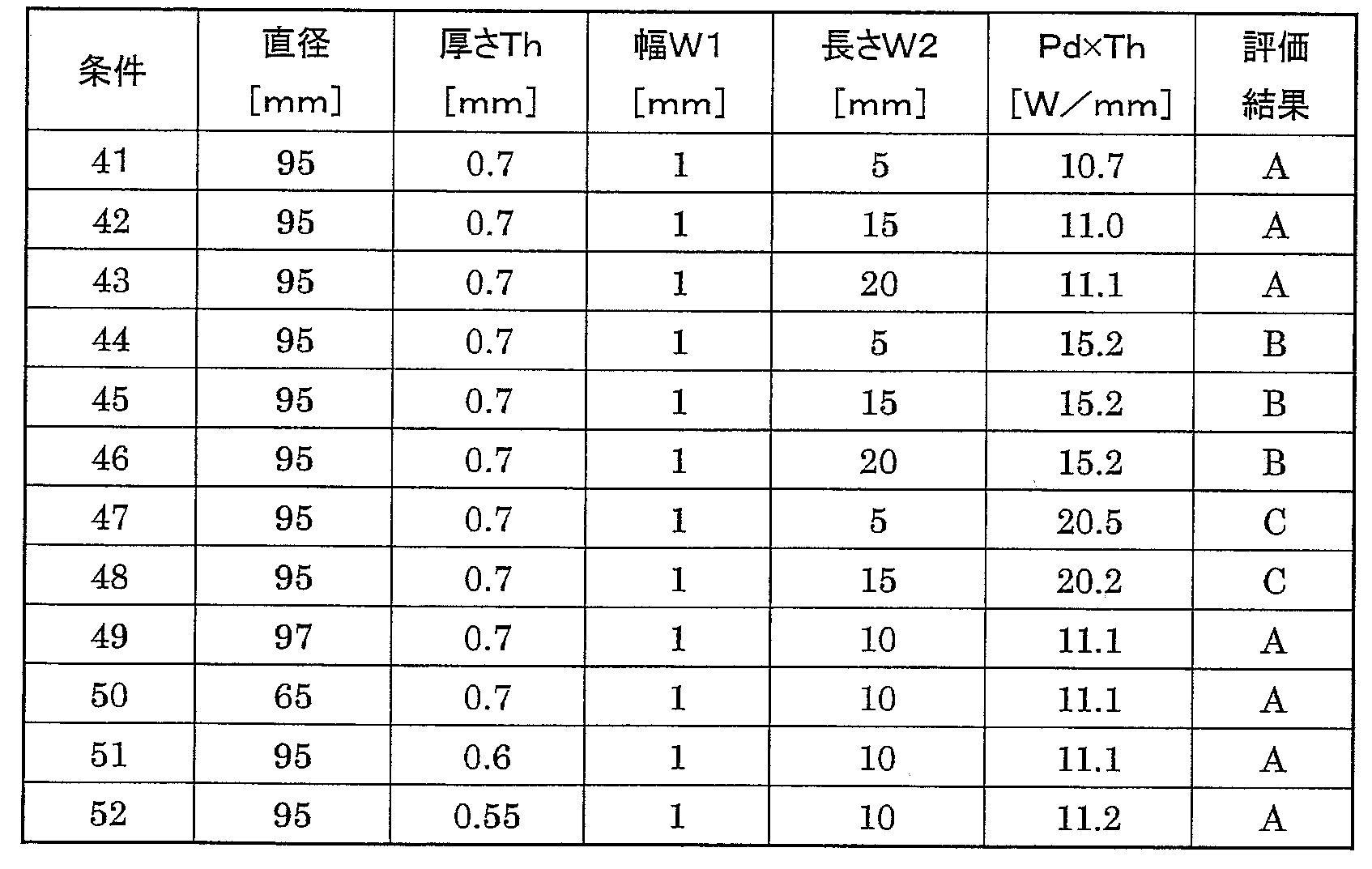
図6より、面取り面14cを形成することができる条件は、移動速度Vが0.7[mm/秒]以上の場合、面取り面14cを形成する評価A~Cを得るには、少なくともPd×Thは、0.8[W/mm]以上である。移動速度Vが0.7[mm/秒]未満になると、評価A,BとなるPd×Thの範囲は極めて狭くなるので、垂直な面と面取り面14cとがある形状が得られたとしても、Pd×Thを少し増加させただけで、端面14が過度に熱されて図5(c)に示すような形状になり易く、安定した生産が行いにくい。この点で、移動速度Vは0.7[mm/秒]以上であることが好ましい。
また、評価Cを避け、評価Bを得るために、すなわち、端面14は、主表面12に垂直な面を備えず、面取り面14cだけを備え、面取り形成部の厚さ方向の長さは元のガラス板の厚さと同等かそれよりより短いガラス板10(図5(c)参照)を得るために、Pd×Thをxとし、移動速度Vをyとしたとき、5.4・x-4.5未満、かつ、3.8・x-5.6以上の範囲内となるようにPd×Thの値と移動速度Vの値を調節することが好ましい。図6に示す直線L3が、y=3.8・x-5.6の直線を示す。
なお、表1,2における評価A,Bとなった条件では、いずれも比(C/Th)が、0.1~0.7の範囲内であった。また、評価A~Cとなった条件で、全て表面粗さRzは0.3μm以下、算術平均粗さRaは0.03μm以下であった。
以上より、本実施形態のガラス板の製造方法の効果は明らかである。
12 主表面
14 端面
14c 面取り面
14t 側壁面
16 円孔
20 レーザー光源
22 光学系
24 集束レンズ
Claims (17)
- 円盤形状のガラス板の端面の形状加工を行うガラス板の製造方法であって、
円盤形状の前記ガラス板は、主表面と、前記主表面に垂直な端面とを有し、
前記端面にレーザー光を照射し、前記端面に対して前記レーザー光を前記円盤形状の前記ガラス板の周方向に相対的に移動しながら、前記端面を目標とする形状に加工するステップを含み、
前記端面に照射する前記レーザー光の断面強度分布はシングルモードであって、前記端面における照射位置上の前記レーザー光の光束の前記ガラス板の厚さ方向の幅をW1[mm]とし、前記ガラス板の厚さをTh[mm]とし、前記レーザー光のパワー密度をPdとしたとき、W1>Thであって、Pd×Thは、0.8~3.5[W/mm]である、ことを特徴とするガラス板の製造方法。 - 円盤形状のガラス板の端面の形状加工を行うガラス板の製造方法であって、
円盤形状の前記ガラス板は、主表面と、前記主表面に垂直な端面とを有し、
前記端面にレーザー光を照射し、前記端面に対して前記レーザー光を前記円盤形状の前記ガラス板の周方向に相対的に移動しながら、前記端面に面取り面を形成して目標とする形状に加工するステップを含み、
前記端面に照射する前記レーザー光の断面強度分布はシングルモードであって、前記端面における照射位置上の前記レーザー光の光束の前記ガラス板の厚さ方向の幅をW1[mm]とし、前記ガラス板の厚さをTh[mm]とし、前記レーザー光のパワー密度をPdとしたとき、W1>Thであって、Pd×Thをx、前記レーザー光の前記端面に沿って移動する移動速度をyとしたとき、yは、11.2・x-4.7以下の範囲内となるように前記Pd×Thの値と前記移動速度の値を調節する、ことを特徴とするガラス板の製造方法。 - 前記レーザー光は、前記ガラス板の前記端面に、前記端面の法線方向から照射される、請求項1または2に記載のガラス板の製造方法。
- 前記形状加工では、前記端面に、前記ガラス板の対向する2つの主表面に対して直交する側壁面と、前記側壁面の両側の端と、前記主表面の端とを接続する面取り面と、を形成するように、前記レーザー光の照射条件は設定される、請求項1~3のいずれか1項に記載のガラス板の製造方法。
- 前記面取り面の前記主表面に沿った長さCの、前記厚さThに対する比(C/Th)が、0.1~0.7となるように、前記照射条件が設定される、請求項4に記載のガラス板の製造方法。
- 前記レーザー光により形成された前記端面の表面粗さRzは、0.3μm以下であり、算術平均粗さRaは0.03μm以下である、請求項1~5のいずれか1項に記載のガラス板の製造方法。
- 前記端面に照射する前記レーザー光の光束は、楕円形状をしており、前記端面に照射される前記レーザー光の光束の前記周方向の長さW2の前記ガラス板の直径Dに対する比(W2/D)は、0.03~0.3である、請求項1~6のいずれか1項に記載のガラス板の製造方法。
- 前記レーザー光の照射により形成された前記ガラス板の直径は、前記レーザー光の照射前の前記ガラス板の直径に比べて増大するように前記パワー密度Pdは設定される、請求項1~7のいずれか1項に記載のガラス板の製造方法。
- 前記レーザー光の前記端面に沿って移動する移動速度は、0.7~100[mm/秒]である、請求項1~8のいずれか1項に記載のガラス板の製造方法。
- 前記ガラス板のヤング率は、70[GPa]以上である、請求項1~9のいずれか1項に記載のガラス板の製造方法。
- 前記ガラス板は、線膨張係数が100×10-7[1/K〕以下である、請求項1~10のいずれか1項に記載のガラス板の製造方法。
- 前記厚さThは、0.7mm以下である、請求項1~11のいずれか1項に記載のガラス板の製造方法。
- 前記ガラス板の製造方法は、前記形状加工を行った前記ガラス板の前記主表面を研削あるいは研磨するステップを含み、
前記形状加工後、前記主表面の研削あるいは研磨の前に、前記端面の研磨を行わない、あるいは、前記端面の研磨を行っても、前記端面の研磨による取り代量は5μm以下である、請求項1~12のいずれか1項に記載のガラス板の製造方法。 - レーザー光の照射により円盤形状のガラス板の端面に面取り面を形成するガラス板の面取り方法であって、
前記面取り面の形成前の前記ガラス板の前記端面は、少なくとも前記ガラス板の厚さ方向の中心部において主表面に対して垂直な面を有し、
前記ガラス板の前記端面へのレーザー光の照射によって前記ガラス板の前記端面のエッジ部を軟化及び/又は溶融させて、前記エッジ部を、丸みを帯びた形状に面取りするとともに、前記面取り面の形成後の前記端面においても前記ガラス板の主表面に垂直な面が形成されるように、前記ガラス板の厚さをTh[mm]とし、前記レーザー光のパワー密度をPdとし、前記レーザー光の前記端面に沿って移動する移動速度をVとしたとき、Pd×Thと移動速度Vとを制御する、
ことを特徴とするガラス板の面取り方法。 - 前記Pd×Thをx、前記移動速度をyとしたとき、
yは、11.2・x-4.7以下、かつ、5.4・x-4.5以上、の範囲内となるように前記Pd×Thの値と前記移動速度の値を調節する、請求項14に記載のガラス板の面取り方法。 - 請求項14または15に記載のガラス板の面取り方法を用いて、円盤形状のガラス板の前記端面の面取り加工を行う、ことを特徴とするガラス板の製造方法。
- 請求項1~13及び請求項16のいずれか1項に記載のガラス板の製造方法により製造されたガラス板の前記主表面に磁性膜を形成する、ことを特徴とする磁気ディスクの製造方法。
Priority Applications (6)
| Application Number | Priority Date | Filing Date | Title |
|---|---|---|---|
| SG11202103948VA SG11202103948VA (en) | 2018-11-30 | 2019-12-02 | Method for manufacturing glass plate, method for chamfering glass plate, and method for manufacturing magnetic disk |
| CN201980077168.3A CN113165940B (zh) | 2018-11-30 | 2019-12-02 | 玻璃板的制造方法、玻璃板的倒角方法和磁盘的制造方法 |
| MYPI2021002190A MY205265A (en) | 2018-11-30 | 2019-12-02 | Method for manufacturing glass plate, method for chamfering glass plate, and method for manufacturing magnetic disk |
| US17/297,973 US12330982B2 (en) | 2018-11-30 | 2019-12-02 | Method for manufacturing glass plate, method for chamfering glass plate, and method for manufacturing magnetic disk |
| JP2020557891A JP7227273B2 (ja) | 2018-11-30 | 2019-12-02 | ガラス板の製造方法、ガラス板の面取り方法、および磁気ディスクの製造方法 |
| JP2023018055A JP7387927B2 (ja) | 2018-11-30 | 2023-02-09 | ガラス板の製造方法、ガラス板の面取り方法、および磁気ディスクの製造方法 |
Applications Claiming Priority (2)
| Application Number | Priority Date | Filing Date | Title |
|---|---|---|---|
| JP2018225568 | 2018-11-30 | ||
| JP2018-225568 | 2018-11-30 |
Publications (1)
| Publication Number | Publication Date |
|---|---|
| WO2020111282A1 true WO2020111282A1 (ja) | 2020-06-04 |
Family
ID=70853327
Family Applications (1)
| Application Number | Title | Priority Date | Filing Date |
|---|---|---|---|
| PCT/JP2019/047102 Ceased WO2020111282A1 (ja) | 2018-11-30 | 2019-12-02 | ガラス板の製造方法、ガラス板の面取り方法、および磁気ディスクの製造方法 |
Country Status (6)
| Country | Link |
|---|---|
| US (1) | US12330982B2 (ja) |
| JP (2) | JP7227273B2 (ja) |
| CN (1) | CN113165940B (ja) |
| MY (1) | MY205265A (ja) |
| SG (1) | SG11202103948VA (ja) |
| WO (1) | WO2020111282A1 (ja) |
Cited By (5)
| Publication number | Priority date | Publication date | Assignee | Title |
|---|---|---|---|---|
| WO2022114060A1 (ja) * | 2020-11-25 | 2022-06-02 | Hoya株式会社 | ガラス板の製造方法、磁気ディスク用ガラス基板の製造方法、磁気ディスクの製造方法、及び円環形状のガラス板 |
| WO2022196314A1 (ja) * | 2021-03-19 | 2022-09-22 | 株式会社Uacj | 磁気ディスク装置および磁気ディスク装置を製造する方法 |
| JP2023065423A (ja) * | 2018-11-30 | 2023-05-12 | Hoya株式会社 | ガラス板の製造方法、ガラス板の面取り方法、および磁気ディスクの製造方法 |
| KR20230086402A (ko) * | 2021-12-08 | 2023-06-15 | (주)하나기술 | 레이저를 이용한 초박막 유리의 측면 가공 방법 및 가공된 초박막 유리 |
| CN116745244A (zh) * | 2021-01-28 | 2023-09-12 | 豪雅株式会社 | 玻璃板的制造方法、磁盘用玻璃基板的制造方法、磁盘的制造方法和玻璃板的处理装置 |
Families Citing this family (4)
| Publication number | Priority date | Publication date | Assignee | Title |
|---|---|---|---|---|
| WO2019151185A1 (ja) * | 2018-01-31 | 2019-08-08 | Hoya株式会社 | 磁気ディスク用ガラス基板の製造方法 |
| DE102018126053A1 (de) * | 2018-10-19 | 2020-04-23 | Schott Schweiz Ag | Verfahren und Vorrichtung zur Heißumformung von gläsernen Werkstücken und heißumgeformte Glasbehälter |
| KR102853012B1 (ko) * | 2024-08-21 | 2025-09-02 | (주)하나기술 | 곡면 코너부를 갖는 유리 기판 형성방법 및 유리 기판 |
| CN119252135B (zh) * | 2024-08-30 | 2026-04-07 | 京东方科技集团股份有限公司 | 玻璃盖板、显示模组和玻璃盖板的制作方法 |
Citations (7)
| Publication number | Priority date | Publication date | Assignee | Title |
|---|---|---|---|---|
| JP2002150546A (ja) * | 2000-11-06 | 2002-05-24 | Nippon Sheet Glass Co Ltd | 情報記録媒体用ガラス基板の製造方法、及び該製造方法により製造された情報記録媒体用ガラス基板、並びに情報記録媒体 |
| US6521862B1 (en) * | 2001-10-09 | 2003-02-18 | International Business Machines Corporation | Apparatus and method for improving chamfer quality of disk edge surfaces with laser treatment |
| WO2007094160A1 (ja) * | 2006-02-15 | 2007-08-23 | Asahi Glass Company, Limited | ガラス基板の面取り方法および装置 |
| JP2010519164A (ja) * | 2007-02-23 | 2010-06-03 | コーニング インコーポレイテッド | 熱的エッジ仕上げ |
| JP2016534012A (ja) * | 2013-08-23 | 2016-11-04 | ラスコム・リミテッド | ガラス製品の鋭いエッジを鈍くする方法 |
| JP2017197414A (ja) * | 2016-04-28 | 2017-11-02 | 日本電気硝子株式会社 | 円形状ガラス板及びその製造方法 |
| JP2018123013A (ja) * | 2017-01-30 | 2018-08-09 | 日本電気硝子株式会社 | 板ガラスの製造方法及び製造装置 |
Family Cites Families (9)
| Publication number | Priority date | Publication date | Assignee | Title |
|---|---|---|---|---|
| US20120247155A1 (en) * | 2011-03-30 | 2012-10-04 | Hoya Corporation | Method of manufacturing glass blank for magnetic recording medium glass substrate, method of manufacturing magnetic recording medium glass substrate, method of manufacturing magnetic recording medium, and apparatus for manufacturing glass blank for magnetic recording medium glass substrate |
| JP5335983B2 (ja) | 2011-10-05 | 2013-11-06 | Hoya株式会社 | 磁気ディスク用ガラス基板および磁気記録媒体 |
| JP6379392B2 (ja) | 2013-05-28 | 2018-08-29 | Agc株式会社 | ガラス基板の切断方法及びガラス基板の製造方法 |
| JP2015076115A (ja) * | 2013-10-11 | 2015-04-20 | 旭硝子株式会社 | 磁気記録媒体用円盤状ガラス基板、及び磁気記録媒体用円盤状ガラス基板の製造方法 |
| US10442719B2 (en) | 2013-12-17 | 2019-10-15 | Corning Incorporated | Edge chamfering methods |
| CN107922259B (zh) | 2015-09-04 | 2021-05-07 | Agc株式会社 | 玻璃板的制造方法、玻璃板、玻璃物品的制造方法、玻璃物品以及玻璃物品的制造装置 |
| JP6385595B2 (ja) * | 2015-12-28 | 2018-09-05 | Hoya株式会社 | 円環状のガラス素板、円環状のガラス素板の製造方法、円環状のガラス基板の製造方法、及び磁気ディスク用ガラス基板の製造方法 |
| WO2020111282A1 (ja) | 2018-11-30 | 2020-06-04 | Hoya株式会社 | ガラス板の製造方法、ガラス板の面取り方法、および磁気ディスクの製造方法 |
| WO2020262702A1 (ja) * | 2019-06-28 | 2020-12-30 | Hoya株式会社 | ガラス板の製造方法および磁気ディスクの製造方法 |
-
2019
- 2019-12-02 WO PCT/JP2019/047102 patent/WO2020111282A1/ja not_active Ceased
- 2019-12-02 CN CN201980077168.3A patent/CN113165940B/zh active Active
- 2019-12-02 US US17/297,973 patent/US12330982B2/en active Active
- 2019-12-02 JP JP2020557891A patent/JP7227273B2/ja active Active
- 2019-12-02 SG SG11202103948VA patent/SG11202103948VA/en unknown
- 2019-12-02 MY MYPI2021002190A patent/MY205265A/en unknown
-
2023
- 2023-02-09 JP JP2023018055A patent/JP7387927B2/ja active Active
Patent Citations (7)
| Publication number | Priority date | Publication date | Assignee | Title |
|---|---|---|---|---|
| JP2002150546A (ja) * | 2000-11-06 | 2002-05-24 | Nippon Sheet Glass Co Ltd | 情報記録媒体用ガラス基板の製造方法、及び該製造方法により製造された情報記録媒体用ガラス基板、並びに情報記録媒体 |
| US6521862B1 (en) * | 2001-10-09 | 2003-02-18 | International Business Machines Corporation | Apparatus and method for improving chamfer quality of disk edge surfaces with laser treatment |
| WO2007094160A1 (ja) * | 2006-02-15 | 2007-08-23 | Asahi Glass Company, Limited | ガラス基板の面取り方法および装置 |
| JP2010519164A (ja) * | 2007-02-23 | 2010-06-03 | コーニング インコーポレイテッド | 熱的エッジ仕上げ |
| JP2016534012A (ja) * | 2013-08-23 | 2016-11-04 | ラスコム・リミテッド | ガラス製品の鋭いエッジを鈍くする方法 |
| JP2017197414A (ja) * | 2016-04-28 | 2017-11-02 | 日本電気硝子株式会社 | 円形状ガラス板及びその製造方法 |
| JP2018123013A (ja) * | 2017-01-30 | 2018-08-09 | 日本電気硝子株式会社 | 板ガラスの製造方法及び製造装置 |
Cited By (16)
| Publication number | Priority date | Publication date | Assignee | Title |
|---|---|---|---|---|
| JP7387927B2 (ja) | 2018-11-30 | 2023-11-28 | Hoya株式会社 | ガラス板の製造方法、ガラス板の面取り方法、および磁気ディスクの製造方法 |
| JP2023065423A (ja) * | 2018-11-30 | 2023-05-12 | Hoya株式会社 | ガラス板の製造方法、ガラス板の面取り方法、および磁気ディスクの製造方法 |
| US12330982B2 (en) | 2018-11-30 | 2025-06-17 | Hoya Corporation | Method for manufacturing glass plate, method for chamfering glass plate, and method for manufacturing magnetic disk |
| US20240018031A1 (en) * | 2020-11-25 | 2024-01-18 | Hoya Corporation | Method for manufacturing glass plate, method for manufacturing glass substrate for magnetic disk, method for manufacturing magnetic disk, and annular glass plate |
| JPWO2022114060A1 (ja) * | 2020-11-25 | 2022-06-02 | ||
| CN116457313A (zh) * | 2020-11-25 | 2023-07-18 | 豪雅株式会社 | 玻璃板的制造方法、磁盘用玻璃基板的制造方法、磁盘的制造方法以及圆环形状的玻璃板 |
| WO2022114060A1 (ja) * | 2020-11-25 | 2022-06-02 | Hoya株式会社 | ガラス板の製造方法、磁気ディスク用ガラス基板の製造方法、磁気ディスクの製造方法、及び円環形状のガラス板 |
| JP7523579B2 (ja) | 2020-11-25 | 2024-07-26 | Hoya株式会社 | ガラス板の製造方法、磁気ディスク用ガラス基板の製造方法、磁気ディスクの製造方法、及び円環形状のガラス板 |
| US12595202B2 (en) * | 2020-11-25 | 2026-04-07 | Hoya Corporation | Method for manufacturing glass plate including processing for chamfering edge surface |
| CN116745244A (zh) * | 2021-01-28 | 2023-09-12 | 豪雅株式会社 | 玻璃板的制造方法、磁盘用玻璃基板的制造方法、磁盘的制造方法和玻璃板的处理装置 |
| JPWO2022196314A1 (ja) * | 2021-03-19 | 2022-09-22 | ||
| JP7633378B2 (ja) | 2021-03-19 | 2025-02-19 | 株式会社Uacj | 磁気ディスク装置および磁気ディスク装置を製造する方法 |
| WO2022196314A1 (ja) * | 2021-03-19 | 2022-09-22 | 株式会社Uacj | 磁気ディスク装置および磁気ディスク装置を製造する方法 |
| US12394440B2 (en) | 2021-03-19 | 2025-08-19 | Uacj Corporation | Magnetic disk device and method for manufacturing magnetic disk device |
| KR20230086402A (ko) * | 2021-12-08 | 2023-06-15 | (주)하나기술 | 레이저를 이용한 초박막 유리의 측면 가공 방법 및 가공된 초박막 유리 |
| KR102652560B1 (ko) * | 2021-12-08 | 2024-03-29 | (주)하나기술 | 레이저를 이용한 초박막 유리의 측면 가공 방법 및 가공된 초박막 유리 |
Also Published As
| Publication number | Publication date |
|---|---|
| JP2023065423A (ja) | 2023-05-12 |
| US20220089479A1 (en) | 2022-03-24 |
| CN113165940B (zh) | 2024-02-20 |
| SG11202103948VA (en) | 2021-05-28 |
| JP7227273B2 (ja) | 2023-02-21 |
| JP7387927B2 (ja) | 2023-11-28 |
| CN113165940A (zh) | 2021-07-23 |
| MY205265A (en) | 2024-10-10 |
| JPWO2020111282A1 (ja) | 2021-11-04 |
| US12330982B2 (en) | 2025-06-17 |
Similar Documents
| Publication | Publication Date | Title |
|---|---|---|
| JP7387927B2 (ja) | ガラス板の製造方法、ガラス板の面取り方法、および磁気ディスクの製造方法 | |
| JP7311702B2 (ja) | ガラス板および磁気ディスク | |
| JP7411660B2 (ja) | 円環形状のガラス板の製造方法、磁気ディスク用ガラス基板の製造方法、磁気ディスクの製造方法、円環形状のガラス板、磁気ディスク用ガラス基板、及び磁気ディスク | |
| US20240400435A1 (en) | Disk-shaped glass plate, method for manufacturing disk-shaped glass blank, and method for manufacturing glass substrate for magnetic disk | |
| JP7458335B2 (ja) | ガラス基板の製造方法及び磁気ディスクの製造方法 | |
| US12344545B2 (en) | Method for manufacturing glass plate, method for manufacturing magnetic-disk glass substrate, and method for manufacturing magnetic disk | |
| US12595202B2 (en) | Method for manufacturing glass plate including processing for chamfering edge surface | |
| US20240101473A1 (en) | Method for manufacturing glass plate, method for manufacturing glass substrate for magnetic disk, method for manufacturing magnetic disk, and apparatus for processing glass plate |
Legal Events
| Date | Code | Title | Description |
|---|---|---|---|
| 121 | Ep: the epo has been informed by wipo that ep was designated in this application |
Ref document number: 19888461 Country of ref document: EP Kind code of ref document: A1 |
|
| ENP | Entry into the national phase |
Ref document number: 2020557891 Country of ref document: JP Kind code of ref document: A |
|
| NENP | Non-entry into the national phase |
Ref country code: DE |
|
| 122 | Ep: pct application non-entry in european phase |
Ref document number: 19888461 Country of ref document: EP Kind code of ref document: A1 |
|
| WWG | Wipo information: grant in national office |
Ref document number: 17297973 Country of ref document: US |