WO2020111088A1 - 自動操舵システム、自動操舵方法および自動操舵プログラム - Google Patents
自動操舵システム、自動操舵方法および自動操舵プログラム Download PDFInfo
- Publication number
- WO2020111088A1 WO2020111088A1 PCT/JP2019/046267 JP2019046267W WO2020111088A1 WO 2020111088 A1 WO2020111088 A1 WO 2020111088A1 JP 2019046267 W JP2019046267 W JP 2019046267W WO 2020111088 A1 WO2020111088 A1 WO 2020111088A1
- Authority
- WO
- WIPO (PCT)
- Prior art keywords
- turning
- steering
- amount
- reference point
- deviation amount
- Prior art date
- Legal status (The legal status is an assumption and is not a legal conclusion. Google has not performed a legal analysis and makes no representation as to the accuracy of the status listed.)
- Ceased
Links
Images





Classifications
-
- A—HUMAN NECESSITIES
- A01—AGRICULTURE; FORESTRY; ANIMAL HUSBANDRY; HUNTING; TRAPPING; FISHING
- A01B—SOIL WORKING IN AGRICULTURE OR FORESTRY; PARTS, DETAILS, OR ACCESSORIES OF AGRICULTURAL MACHINES OR IMPLEMENTS, IN GENERAL
- A01B69/00—Steering of agricultural machines or implements; Guiding agricultural machines or implements on a desired track
- A01B69/007—Steering or guiding of agricultural vehicles, e.g. steering of the tractor to keep the plough in the furrow
- A01B69/008—Steering or guiding of agricultural vehicles, e.g. steering of the tractor to keep the plough in the furrow automatic
-
- A—HUMAN NECESSITIES
- A01—AGRICULTURE; FORESTRY; ANIMAL HUSBANDRY; HUNTING; TRAPPING; FISHING
- A01B—SOIL WORKING IN AGRICULTURE OR FORESTRY; PARTS, DETAILS, OR ACCESSORIES OF AGRICULTURAL MACHINES OR IMPLEMENTS, IN GENERAL
- A01B69/00—Steering of agricultural machines or implements; Guiding agricultural machines or implements on a desired track
-
- A—HUMAN NECESSITIES
- A01—AGRICULTURE; FORESTRY; ANIMAL HUSBANDRY; HUNTING; TRAPPING; FISHING
- A01D—HARVESTING; MOWING
- A01D41/00—Combines, i.e. harvesters or mowers combined with threshing devices
- A01D41/12—Details of combines
- A01D41/127—Control or measuring arrangements specially adapted for combines
- A01D41/1278—Control or measuring arrangements specially adapted for combines for automatic steering
-
- G—PHYSICS
- G05—CONTROLLING; REGULATING
- G05D—SYSTEMS FOR CONTROLLING OR REGULATING NON-ELECTRIC VARIABLES
- G05D1/00—Control of position, course, altitude or attitude of land, water, air or space vehicles, e.g. using automatic pilots
- G05D1/02—Control of position or course in two dimensions
-
- G—PHYSICS
- G05—CONTROLLING; REGULATING
- G05D—SYSTEMS FOR CONTROLLING OR REGULATING NON-ELECTRIC VARIABLES
- G05D3/00—Control of position or direction
- G05D3/12—Control of position or direction using feedback
-
- B—PERFORMING OPERATIONS; TRANSPORTING
- B60—VEHICLES IN GENERAL
- B60Y—INDEXING SCHEME RELATING TO ASPECTS CROSS-CUTTING VEHICLE TECHNOLOGY
- B60Y2200/00—Type of vehicle
- B60Y2200/20—Off-Road Vehicles
- B60Y2200/22—Agricultural vehicles
- B60Y2200/222—Harvesters
Definitions
- the present invention relates to an automatic steering system, an automatic steering method and an automatic steering program for automatically traveling a work vehicle along a set turning circle.
- the agricultural work vehicle according to Patent Document 1 is equipped with a GPS receiver that receives radio waves from GPS satellites, and automatically travels so as to follow the target route based on the calculated vehicle position.
- position deviation positional deviation
- heading deviation Steering control is performed based on the (direction deviation).
- the front wheel center on the front side of the vehicle body is set as the control reference position, and the straight line connecting the center of the turning route and the control reference position, and the turning route, the tangential vector of the vehicle body passing through the intersection of the control reference position
- the position deviation and azimuth deviation are calculated. Steering control is performed based on the calculated position deviation and azimuth deviation.
- the influence of the steering control on the vehicle body and the field varies depending on whether the vehicle body is inside or outside the turning path. For example, when the vehicle body is outside the turning path, the steering directions are the same and the steering amount is only increased. On the other hand, when the vehicle body is inside the turning path, not only the steering amount increases but also the steering direction is steered in the opposite direction before and after the control. Therefore, if steering control is performed using both the amount of positional deviation and the amount of heading deviation, when the vehicle body is inside the turning path, the steering direction reverses and the amount of change in the steering angle becomes too large. There were cases where the field became unstable and the field was damaged.
- An automatic steering system is an automatic steering system that automatically runs a work vehicle along a set turning circle, and includes a reference point calculation unit that calculates a position of a reference point in the work vehicle.
- a reference straight line calculation unit that calculates a straight line that passes through the center of the turning circle and the reference point as a reference straight line;
- a vehicle body azimuth calculation unit that calculates a vehicle body azimuth indicating the direction of the body of the working vehicle;
- a direction deviation amount calculation unit that calculates an intersection angle between a line perpendicular to the reference straight line and the vehicle body direction as a direction deviation amount, and a deviation direction determination unit that determines a positional relationship between the reference point and the outer circumference of the turning circle.
- a steering control unit that outputs a steering amount that reduces the bearing deviation when the reference point is located inside the outer circumference of the turning circle.
- the steering control is based on only the direction deviation amount. Done.
- the steering control unit calculates and outputs the steering amount by a PID control method or a PI control method using the current steering amount and the heading deviation amount as input parameters.
- An automatic steering method is an automatic steering method for automatically traveling a work vehicle along a set turning circle, the method comprising: calculating a position of a reference point in the work vehicle; A step of calculating a straight line passing through the center of a circle and the reference point as a reference straight line; a step of calculating a vehicle body azimuth indicating the direction of the vehicle body of the working vehicle; and a line passing through the reference point and perpendicular to the reference straight line. Calculating a crossing angle with the vehicle body azimuth as an azimuth deviation amount; determining a positional relationship between the reference point and the outer circumference of the turning circle; and the reference point located inside the outer circumference of the turning circle. In this case, a step of outputting a steering amount that reduces the bearing deviation amount is included.
- the output steering amount is preferably calculated by the PID control method or the PI control method using the current steering amount and the heading deviation amount as input parameters.
- the method includes a step of calculating a distance from the intersection of the reference straight line and the turning circle to the reference point as a positional deviation amount, and when the reference point is located outside the outer circumference of the turning circle, the output is performed.
- the steering amount is preferably a steering amount in which the position shift amount and the azimuth shift amount are small.
- the output steering amount is preferably calculated by the PID control method or the PI control method using the current steering amount, the position deviation amount, and the heading deviation amount as input parameters.
- An automatic steering program is an automatic steering program for automatically traveling a work vehicle along a set turning circle, including a procedure for calculating the position of a reference point in the work vehicle, and the turning operation.
- the procedure is for causing the computer to execute the procedure of outputting the steering amount with which the direction deviation amount becomes small.
- the output steering amount is preferably calculated by the PID control method or the PI control method using the current steering amount and the heading deviation amount as input parameters.
- the steering amount to be set is a steering amount that reduces the positional deviation amount and the heading deviation amount.
- the output steering amount is preferably calculated by the PID control method or the PI control method using the current steering amount, the position deviation amount, and the heading deviation amount as input parameters.
- the control gain in the PID control method and the PI control method is the reference point when the reference point is located outside the outer circumference of the turning circle. May be larger than the case where is located inside the outer circumference of the turning circle.
- the control gain can be made smaller than when it is displaced outside the turning circle, and the steering control amount relative to the displacement amount can be reduced.
- sudden turning of the work vehicle is reliably suppressed, and accurate and more appropriate steering control is possible.
- the heading deviation amount may be excluded from the input parameters.
- the direction deviation amount when the direction deviation amount is smaller than a predetermined angle, the direction deviation amount may be excluded from the input parameters.
- a turning circle for sudden turning and a turning circle for gentle turning having a radius larger than the turning circle for rapid turning may be selectably prepared.
- front direction of arrow F shown in FIG. 1
- rear arrow B shown in FIG. 1
- left-right direction or the lateral direction means a vehicle body transverse direction (vehicle body width direction) orthogonal to the vehicle body front-rear direction.
- Upper direction of arrow U shown in FIG. 1
- lower direction of arrow D shown in FIG. 1
- this combine has a traveling vehicle body (corresponding to a working vehicle) 10, a crawler type traveling device 11, a driving unit 12, a threshing device 13, a grain tank 14, a harvesting unit H, a conveying device 16, a grain. It is provided with a grain discharging device 18 and a vehicle position detecting module 80.
- the traveling device 11 is provided below the traveling vehicle body 10 (hereinafter simply referred to as the vehicle body 10).
- the combine is configured to be self-propelled by the traveling device 11.
- the traveling device 11 is a steering traveling device including a pair of left and right crawler mechanisms (traveling units).
- the crawler speed of the left crawler mechanism (left traveling unit) and the crawler speed of the right crawler mechanism (right traveling unit) can be adjusted independently, and by adjusting the speed difference, the direction of the vehicle body 10 in the traveling direction can be adjusted. Be changed.
- the operating unit 12, the threshing device 13, and the grain tank 14 are provided on the upper side of the traveling device 11 and constitute the upper part of the vehicle body 10.
- a driver who drives the combine or a monitor who monitors the operation of the combine can board the operation unit 12. Normally, the driver and the supervisor are combined. When the driver and the monitor are different persons, the monitor may monitor the combine operation from outside the combine.
- the grain discharging device 18 is connected to the lower rear portion of the grain tank 14.
- the own vehicle position detection module 80 is attached to the upper front part of the driving unit 12.
- the harvesting section H is provided at the front of the combine.
- the transport device 16 is connected to the rear side of the harvesting section H.
- the harvesting section H also has a cutting mechanism 15 and a reel 17.
- the cutting mechanism 15 cuts the planted grain culms in the field. Further, the reel 17 scrapes the planted grain culm to be harvested while being rotationally driven.
- the harvesting unit H harvests grain (a type of agricultural crop) in the field. Then, the combine can perform work traveling in which the traveling device 11 travels while harvesting the grain in the field by the harvesting unit H.
- the cut culm cut by the cutting mechanism 15 is transferred to the threshing device 13 by the transfer device 16.
- the cut culm is threshed.
- the grain obtained by the threshing process is stored in the grain tank 14.
- the grain stored in the grain tank 14 is discharged to the outside by the grain discharging device 18.
- a communication terminal 2 is arranged in the operation unit 12.
- the communication terminal 2 is fixed to the driving unit 12.
- the present invention is not limited to this, and the communication terminal 2 may be configured to be detachable from the driving unit 12. Also, the communication terminal 2 may be taken out of the combine.
- the vehicle position detection module 80 includes a satellite navigation module 81 and an inertial navigation module 82.
- the satellite navigation module 81 receives a GNSS (global navigation satellite system) signal (including a GPS signal) from the artificial satellite GS and outputs positioning data for calculating the vehicle position.
- the inertial navigation module 82 incorporates a gyro acceleration sensor and a magnetic bearing sensor, and outputs a position vector indicating an instantaneous traveling direction.
- the inertial navigation module 82 is used to complement the own vehicle position calculation by the satellite navigation module 81.
- the inertial navigation module 82 may be located at a place different from the satellite navigation module 81.
- the driver/monitor operates the combine manually, and as shown in Fig. 2, in the outer peripheral part of the field, harvesting is performed so as to circulate along the boundary line of the field.
- the area that has become the already-cut land (the already-worked area) is set as the outer peripheral area SA.
- the area left inside the outer peripheral area SA as uncut land (unworked area) is set as the work target area CA.
- FIG. 2 shows an example of the outer peripheral area SA and the work target area CA.
- the driver runs the combine for two or three laps in order to secure the width of the outer peripheral area SA to some extent.
- the width of the outer peripheral area SA is expanded by the working width of the combine every time the combine makes one turn.
- the width of the outer peripheral area SA becomes about two to three times the working width of the combine.
- This round traveling may be performed by automatic traveling based on the field outside shape data given in advance.
- the outer peripheral area SA is used as a space for the combine to change directions when performing harvesting traveling in the work target area CA. Further, the outer peripheral area SA is also used as a moving space when the harvesting run is finished and the grain is moved to a grain discharge place or a fuel supply place.
- the carrier CV shown in FIG. 2 can collect and carry the grains discharged from the combine. At the time of discharging the grain, the combine moves to the vicinity of the carrier CV, and then the grain discharging device 18 discharges the grain to the carrier CV.
- the travel route in the work target area CA is calculated as shown in FIG.
- the calculated travel route is sequentially set based on the work travel pattern, and the combine automatically travels along the set travel route.
- this combine has a U-turning pattern that changes direction along a U-shaped turning route as shown in FIG. 3 and a forward and backward movement as shown in FIG. It has an ⁇ -turning pattern for changing the direction and a switchback turning pattern for changing the same direction as the U-turning pattern in an area narrower than the U-turning pattern with the backward traveling as shown in FIG.
- a 90° turning turn traveling route is shown.
- the route extends from the source traveling route L1 to the destination traveling route L2 via the forward traveling route ML1, the backward traveling route ML2, the forward traveling route ML3.
- the switchback turning pattern of FIG. 5 shows the 180° turn-back turning running used for the path transition in the straight line reciprocating running.
- the route extends from the source traveling route L1 to the destination traveling route L2 via the forward traveling route ML4, the backward traveling route ML5, the forward traveling route ML6.
- the turning traveling including such a reverse movement is also performed when the grain tank 14 is full and the combine, which has left the traveling route of the work target area CA, is aligned with the transport vehicle CV.
- FIG. 6 shows a combine control system using the automatic steering system according to the present invention.
- the control system of the combine is composed of a control unit 5 including a large number of electronic control units called ECUs, and various input/output devices that perform signal communication (data communication) with the control unit 5 through a wiring network such as an in-vehicle LAN. It is configured.
- the notification device 62 is a device for notifying the driver of the work traveling state and various warnings, and includes a buzzer, a lamp, a speaker, a display, and the like.
- the communication unit 66 is used by the combine control system for exchanging data with the communication terminal 2 or with a management computer installed in a remote place.
- the communication terminal 2 also includes a tablet computer operated by an observer standing in the field, or a driver and an observer boarding the combine, a computer installed at home or in a management office, and the like.
- the control unit 5 is a core element of this control system, and is shown as an assembly of a plurality of ECUs.
- the signal from the vehicle position detection module 80 is input to the control unit 5 through the vehicle-mounted LAN.
- the control unit 5 includes an output processing unit 503 and an input processing unit 502 as input/output interfaces.
- the output processing unit 503 is connected to various operating devices 70 via the device driver 65.
- As the operating devices 70 there are a traveling device group 71 that is a traveling-related device and a working device group 72 that is a work-related device.
- the traveling device group 71 includes, for example, a steering device 710, an engine device, a transmission device, a braking device, and the like.
- the work equipment group 72 includes a harvesting unit H (see FIG. 1 ), a threshing device 13 (see FIG. 1 ), a transport device 16 (see FIG. 1 ), a power control device in the grain discharging device 18 (see FIG. 1 ), and the like. include.
- the input processing unit 502 is connected with a traveling state sensor group 63, a work state sensor group 64, a traveling operation unit 90, and the like.
- the traveling state sensor group 63 includes an engine speed sensor, an overheat detection sensor, a brake pedal position detection sensor, a shift position detection sensor, a steering position detection sensor, and the like.
- the work state sensor group 64 includes a sensor that detects a driving state of the harvesting work device (harvesting unit H, threshing device 13, transport device 16, grain discharging device 18), a sensor that detects a state of a culm or a grain, and the like. It is included.
- the traveling operation unit 90 is a general term for operating tools that are manually operated by a driver and an operation signal thereof is input to the control unit 5.
- the traveling operation unit 90 includes a main shift operation tool 91, a steering operation tool 92, a mode operation tool 93, an automatic start operation tool 94, and the like.
- the crawler speed of the left crawler mechanism and the crawler speed of the right crawler mechanism are adjusted by swinging the steering operation tool 92 from the neutral position to the left and right, so that the vehicle body 10 (hereinafter, not shown in FIG. The orientation (see 1) is changed.
- the operation of changing the traveling direction of the vehicle body 10 is generally called steering, and not only changing the direction of the wheels and the like, but also adjusting the speed of the left and right crawlers is called steering.
- the mode operation tool 93 has a function of giving the control unit 5 a command for switching between an automatic traveling mode in which automatic driving is performed and a manual traveling mode in which manual driving is performed.
- the automatic start operation tool 94 has a function of giving the control unit 5 a final automatic start command for starting automatic traveling. Note that, regardless of the operation by the mode operation tool 93, the transition from the automatic traveling mode to the manual traveling mode may be automatically performed by software. For example, when a situation in which automatic driving is impossible occurs, the control unit 5 forcibly executes the shift from the automatic driving mode to the manual driving mode.
- the vehicle position calculation unit 55 functions as a reference point calculation unit that calculates the position of the reference point of the vehicle body 10.
- This reference point includes a vehicle body reference point, a turning reference point, and the like, which will be described later.
- the vehicle body azimuth calculation unit 56 determines a vehicle body azimuth indicating the direction of the vehicle body 10 in the traveling direction by obtaining a traveling locus in a minute time from the own vehicle position sequentially calculated by the own vehicle position calculation unit 55. Further, the vehicle body azimuth calculation unit 56 can also determine the vehicle body azimuth based on the azimuth data included in the output data from the inertial navigation module 82.
- the traveling control unit 51 has an engine control function, a steering control function, a vehicle speed control function, and the like, and gives a control signal to the traveling device group 71.
- the work control unit 52 includes harvesting work devices (such as the harvesting unit H (see FIG. 1 ), the threshing device 13 (see FIG. 1 ), the transport device 16 (see FIG. 1 ), and the grain discharging device 18 (see FIG. 1 )). Control signals are provided to the work equipment group 72 to control the movement.
- the displacement direction determination unit 509 included in the travel control unit 51 is configured to displace the vehicle body 10 inside or outside the turning path based on the displacement amount calculated by the displacement amount calculation unit 57 described below. It is determined.
- the steering control unit 510 included in the traveling control unit 51 is based on at least one of the positional deviation amount calculated by the positional deviation amount calculation unit 57 and the azimuth deviation amount calculated by the azimuth deviation amount calculation unit 58.
- the steering amount is calculated and output to the steering device 710. That is, the steering control unit 510 calculates the positional deviation amount and the heading deviation amount between the target traveling route set by the traveling route setting unit 54 and the own vehicle position calculated by the own vehicle position calculating unit 55. Steering control (turning control) is performed so that at least one becomes smaller.
- the steering control unit 510 employs a PID control method or a PI control method. Of course, other control methods may be adopted. This combine can be driven by both automatic operation for performing harvesting work by automatic traveling and manual operation for performing harvesting work by manual traveling. Therefore, the traveling control unit 51 further includes a manual traveling control unit 511 and an automatic traveling control unit 512. It should be noted that the automatic traveling mode is set when performing the automatic driving, and the manual traveling mode is set when performing the manual driving. As described above, the switching of the driving mode is managed by the driving mode management unit 53.
- the steering control unit 510 of the travel control unit 51 may change the steering control configuration depending on whether the vehicle body 10 is displaced inside or outside the turning path. For example, when the vehicle body 10 is displaced to the outside of the turning path, the steering amount is calculated based on the positional displacement amount and the heading displacement amount, and is output to the steering device 710. Further, when the vehicle body 10 is displaced inside the turning path, the steering amount is calculated based on only the azimuth displacement amount without considering the positional displacement amount and is output to the steering device 710. By controlling in this way, it is possible to prevent the steering direction from being reversed and the amount of change in the steering angle to become too large, which makes the vehicle body 10 unstable and the field rough. As a result, in turning, it is possible to calculate the amount of positional deviation and the amount of azimuth deviation at high speed by a simple calculation method, and perform accurate and appropriate steering control.
- the automatic traveling control unit 512 cooperates with the steering control unit 510 to generate a control signal for changing the vehicle speed including automatic steering and stopping to control the traveling device group 71. .. At this time, the control signal for changing the vehicle speed is generated based on the vehicle speed value set in advance.
- the travel route setting unit 54 sequentially selects a travel route including the managed turning route and sets it as a travel target route.
- the turning path is substantially an arc of a turning circle.
- An arc-shaped turning path is defined by the center of the turning circle and the radius of the turning circle. Assuming that the vehicle body 10 travels on the turning path accurately, the center of this turning circle is the turning center of the vehicle body 10.
- the travel route managed by the travel route setting unit 54 can be generated by the travel route setting unit 54 by a route calculation algorithm, but the one generated by the communication terminal 2 or a remote management computer is downloaded. It is also possible to use.
- the manual traveling control unit 511 When the manual traveling mode is selected, the manual traveling control unit 511 generates a control signal based on the operation by the driver to control the traveling device group 71, thereby realizing the manual driving.
- the travel route calculated by the travel route setting unit 54 can be used for guidance purposes for the combine to travel along the travel route even in manual operation.
- the positional deviation amount calculation unit 57 calculates a positional deviation that is the distance between the traveling route set by the traveling route setting unit 54 and the own vehicle position calculated by the own vehicle position calculation unit 55.
- the azimuth deviation amount calculation unit 58 calculates an angle difference between the extension direction of the traveling route set by the traveling route setting unit 54 and the vehicle body azimuth calculated by the vehicle body azimuth calculation unit 56 as an azimuth deviation.
- the own vehicle position calculated by the own vehicle position calculation unit 55 is set as a turning reference point that is a point on the turning route defined by the turning circle in ideal turning without deviation. ..
- the turning reference point rides on the straight traveling route, so the turning reference point can be used as the vehicle body reference point on the straight traveling route. In that case, the turning reference point and the vehicle body reference point are the same.
- the reference straight line calculation unit 59 calculates a reference straight line.
- the reference straight line is used for the calculation of the positional deviation amount by the positional deviation amount calculation unit 57 and the calculation of the azimuth deviation amount by the azimuth deviation amount calculation unit 58 in the turning traveling. Next, the relationship between the reference straight line, the positional deviation amount, and the azimuth deviation amount will be described using FIG. 7.
- FIG. 7 and 12 show the relationship between the turning circle C and the vehicle body 10 set when the vehicle travels from the pre-turning travel route, which is the pre-turning travel route, to the post-turning travel route, which is the pre-turning travel route. Shows.
- the pre-turning travel route and the post-turning travel route are in an orthogonal relationship, and the turning route is a 90° arc of the turning circle C.
- the vehicle body 10 is displaced outside the turning circle C.
- the pre-turning travel route and the post-turning travel route are in a parallel relationship, and the turning route is a 180° arc of the turning circle C. Further, the vehicle body 10 is displaced inside the turning circle C.
- C indicates a turning circle.
- P is the center of the turning circle C.
- the coordinate value of the center P of the turning circle is (X, Y) and is managed by the travel route setting unit 54.
- R is the radius of the turning circle C.
- VP is a turning reference point (vehicle body reference point) of the vehicle body 10 and is represented by coordinate values (x, y).
- the coordinate value (x, y) of the turning reference point VP is calculated by the vehicle position calculation unit 55.
- CL is a vehicle body center line which is a center line extending in the front-rear direction of the vehicle body 10.
- d is the distance between two points between the center P of the turning circle and the turning reference point VP.
- BL is a straight line connecting the two points of the center P of the turning circle and the turning reference point VP, and this straight line is the “reference straight line”.
- PL is a straight line that passes through the turning reference point VP and is perpendicular to the reference straight line BL, and is hereinafter referred to as an “azimuth reference line”.
- FIG. 7 shows a state in which the vehicle is turning, and the vehicle body 10 is displaced outside the turning circle C, and the vehicle body orientation (vehicle body center line CL) is displaced to the right with respect to the orientation reference line PL.
- FIG. 12 shows a state in which the vehicle is turning, and the vehicle body 10 is displaced inside the turning circle C, and the vehicle body azimuth (vehicle body center line CL) is located on the left side of the azimuth reference line PL. It is out of alignment.
- the reference straight line calculation unit 59 calculates a reference straight line BL by obtaining a straight line equation connecting two points of the center P of the turning circle and the turning reference point VP.
- the positional deviation amount calculation unit 57 calculates the distance d between two points between the center P of the turning circle and the turning reference point VP, and subtracts R from the distance d between the two points to calculate the positional deviation amount ⁇ . In this subtraction, the positive and negative signs are taken into consideration. If the subtraction value is negative, the vehicle body 10 is displaced inside the turning circle C. If the subtraction value is positive, the vehicle body 10 is turning circle C. It means that it is displaced outside of.
- the displacement direction determination unit 509 determines the sign of the displacement amount ⁇ and determines whether the vehicle body 10 is displaced inside or outside the turning circle C.
- the azimuth deviation amount calculation unit 58 calculates the angle (intersection angle) formed by the vehicle body center line CL and the azimuth reference line PL as the azimuth deviation amount ⁇ . If the azimuth deviation amount ⁇ is a positive value, it means that the vehicle body 10 is displaced to the right in the traveling direction, and if the azimuth deviation amount ⁇ is a negative value, the vehicle body 10 is displaced to the left direction in the traveling direction. It will be. In this way, the position shift amount ⁇ and the heading shift amount ⁇ are calculated for each minute travel and are given to the steering control unit 510, whereby the steering amount based on the PID or PI control is output.
- a linear expression of the vehicle body center line CL is obtained based on the vehicle body orientation from the vehicle body orientation calculation unit 56 (step #5 in FIG. 13).
- the azimuth reference line PL perpendicular to the reference straight line BL is calculated based on the linear expression of the reference straight line BL, and the angle (intersection angle) formed by the vehicle body center line CL and the azimuth reference line PL is the azimuth deviation amount ⁇ . It is calculated (step #6 in FIG. 13).
- Whether the vehicle body 10 is displaced inward or outward of the turning circle C is determined from the positive/negative sign of the displacement amount ⁇ (step #7 in FIG. 13).
- the steering amount is calculated from the positional shift amount ⁇ and the heading shift amount ⁇ (step #8 in FIG. 13).
- steering control is performed using the positional deviation amount ⁇ and the heading deviation amount ⁇ , and the vehicle body 10 is displaced inward with respect to the turning circle C.
- the steering control is performed using only the heading deviation amount ⁇ without considering the position deviation amount ⁇ .
- the parameters that determine the amount of displacement in the turning direction and the like are reduced, and rapid turning is suppressed.
- the intersection point with the straight line K2 perpendicular to is obtained, and a circle passing through the intersection reference point VP of the vehicle body 10 at the start of turning and the reference point VP of the vehicle body 10 at the end of turning is an optimized turning circle with the intersection point as the center. Yes, with radius Rc.
- the steering control unit 510 When the positional deviation amount ⁇ is larger than a predetermined value (threshold value) ⁇ T 2 which is set in advance, the steering control unit 510 does not use the azimuth deviation amount ⁇ but only based on the positional deviation amount ⁇ . May be calculated. As a result, even if the amount of displacement is large, excessive steering control is suppressed, and sudden turning is suppressed.
- the steering control unit 510 When the azimuth deviation amount ⁇ is smaller than the predetermined angle (threshold value) ⁇ T 3 , the steering control unit 510 does not use the azimuth deviation amount ⁇ , but only based on the position deviation amount ⁇ . May be calculated. As a result, sensitive turning is suppressed and running stability is ensured.
- the steering control unit 510 determines the control gain used for steering control by the vehicle body 10 to the turning circle C. It may be made smaller than the case where the vehicle body 10 is displaced to the outside, and the steering control may be performed gently when it is determined that the vehicle body 10 is displaced to the inside of the turning circle C.
- the control gain when the vehicle body 10 is displaced outside the turning circle C is 0.8
- the control gain when the vehicle body 10 is displaced inside the turning circle C is 0.6.
- the steering control unit 510 Since the actual turning of the combine is influenced by the amount of the grain stored in the grain tank 7, the steering control unit 510 stores the grain in the grain tank 7 when calculating the steering amount.
- the amount of grains (fir weight) that are present may be considered.
- the turning circle used for the turning route is generated by the traveling route creation algorithm for the field or is included in the artificially generated traveling route.
- the travel route setting unit 54 sequentially sets the target travel route.
- the example in which the radius of the turning circle is automatically changed based on the occurrence of the turning deviation has been described.
- a configuration in which the radius of the turning circle is artificially changed may be adopted.
- there are multiple turning modes such as "moderate mode” in which a turning circle with a large radius (turning circle for gentle turning) is set, and "high speed mode” in which a turning circle with a small radius (turning circle for rapid turning) is selected.
- An artificial operation tool that can be selected may be provided.
- the combination of the satellite navigation module 81 and the inertial navigation module 82 is used as the vehicle position detection module 80, but only the satellite navigation module 81 may be used. Further, a method of calculating the own vehicle position and the vehicle body direction based on the image taken by the camera may be adopted.
- the present invention is applicable not only to ordinary combine harvesters, but also to self-removing combine harvesters. Further, the present invention can be applied to various harvesters such as a corn harvester, a potato harvester, a carrot harvester and a sugar cane harvester, and a field work vehicle such as a rice transplanter and a tractor. Furthermore, the present invention can be applied to lawnmowers and construction machines.
- Traveling vehicle (work vehicle) 55 Own vehicle position calculation unit (reference point calculation unit) 56 Car Body Direction Calculation Unit 57 Position Deviation Amount Calculation Unit 58 Azimuth Difference Amount Calculation Unit 59 Reference Straight Line Calculation Unit 509 Deviation Determination Unit 510 Steering Control Unit BL Reference Straight Line C Turning Circle CL Body Center Line (Vehicle Body Direction) P center PL azimuth reference line VP turning reference point (reference point) ⁇ Amount of misalignment ⁇ Amount of misalignment
Landscapes
- Life Sciences & Earth Sciences (AREA)
- Engineering & Computer Science (AREA)
- Environmental Sciences (AREA)
- Mechanical Engineering (AREA)
- Automation & Control Theory (AREA)
- General Physics & Mathematics (AREA)
- Physics & Mathematics (AREA)
- Soil Sciences (AREA)
- Aviation & Aerospace Engineering (AREA)
- Radar, Positioning & Navigation (AREA)
- Remote Sensing (AREA)
- Guiding Agricultural Machines (AREA)
- Control Of Position, Course, Altitude, Or Attitude Of Moving Bodies (AREA)
Abstract
設定された旋回円に沿って作業車を自動走行させる自動操舵システムであって、作業車における基準点VPの位置を算出する基準点算出部と、旋回円の中心Pと基準点VPとを通る直線を基準直線BLとして算出する基準直線算出部と、作業車の車体の向きを示す車体方位を算出する車体方位算出部と、基準点VPを通り基準直線BLに垂直な線と車体方位との交差角を方位ずれ量θとして算出する方位ずれ量算出部と、基準点VPと旋回円の外周との位置関係を判定するずれ方向判定部と、基準点VPが旋回円の外周より内側に位置する場合、方位ずれ量θが小さくなる操舵量を出力する操舵制御部とを備える。
Description
本発明は、設定された旋回円に沿って作業車を自動走行させる自動操舵システム、自動操舵方法および自動操舵プログラムに関する。
特許文献1による農業用作業車は、GPS衛星からの電波を受信するGPS受信装置を備え、算出された自車位置に基づいて、目標経路に追従するように自動走行する。直進走行では、直線状の目標経路から車体がずれた場合には、つまり、車体中心線上に設置されている制御基準点が目標経路からずれた場合には、位置偏差(位置ずれ)および方位偏差(方位ずれ)に基づいて、操舵制御が行われる。旋回走行では、車体前側の前輪中心部が制御基準位置に設定され、旋回経路の中心と制御基準位置とを結ぶ直線と、旋回経路と、の交点を通る車体の接線ベクトルに対する、制御基準位置の位置偏差と方位偏差が算出される。算出された位置偏差と方位偏差に基づいて操舵制御が行われる。
特許文献1による操舵制御では、位置偏差(位置ずれ量)と方位偏差(方位ずれ量)とを求めるために、旋回経路の旋回中心と制御基準位置とを結ぶ直線と、旋回経路と、の交点を通る車体の接線ベクトルを算出する必要があるが、接線ベクトルの算出は演算負荷が高いので、演算時間がかかる。また、作業車では、乗用車などに比べて小さい旋回半径が用いられるので、旋回走行において接線ベクトルは急速に変化していくことになり、演算負荷の高い接線ベクトルの算出を短時間で行う必要がある。これを行うためには、高いコストの演算機能が要求される。
また、車体が旋回経路の内側にある場合と外側にある場合とで、操舵制御に伴って車体や圃場が受ける影響が異なる。例えば、車体が旋回経路の外側にある場合は、操舵方向は同一で操舵量を増大させるだけである。これに対して、車体が旋回経路の内側にある場合は、操舵量が増大するだけでなく、制御前後で操舵方向が逆向きに操舵される。そのため、位置ずれ量と方位ずれ量との両方を用いて操舵制御を行うと、車体が旋回経路の内側にある場合、操舵方向が逆転して操舵角の変更量が大きくなりすぎ、車体の走行が不安定になったり、圃場を荒らしたりする場合があった。
このような実情に鑑み、旋回走行において、簡単な算法で高速に位置ずれ量および方位ずれ量を算出することができ、正確で適切な操舵制御が可能な自動操舵システムが要望されている。
本発明の一実施形態に係る自動操舵システムは、設定された旋回円に沿って作業車を自動走行させる自動操舵システムであって、前記作業車における基準点の位置を算出する基準点算出部と、前記旋回円の中心と前記基準点とを通る直線を基準直線として算出する基準直線算出部と、前記作業車の車体の向きを示す車体方位を算出する車体方位算出部と、前記基準点を通り前記基準直線に垂直な線と前記車体方位との交差角を方位ずれ量として算出する方位ずれ量算出部と、前記基準点と前記旋回円の外周との位置関係を判定するずれ方向判定部と、前記基準点が前記旋回円の外周より内側に位置する場合、前記方位ずれ量が小さくなる操舵量を出力する操舵制御部とを備える。
作業車が旋回円の外側にずれている場合には、作業車を旋回経路である旋回円上に戻すために、操舵方向が現状の操舵方向と同じで操舵量が多くなるように操舵制御が行われる。これに対して、作業車が旋回円の内側にずれている場合には、作業車を旋回経路である旋回円上に戻すために、操舵方向が現状の操舵方向と逆向きになるように操舵制御が行われる。そのため、作業車が旋回円の内側にずれている場合には、作業車が急激に旋回し、作業車の走行安定性が悪化したり、作業車の旋回により圃場が荒らされる場合があった。このような問題を解決するために、作業車が旋回円の内側にずれている場合には、作業車が旋回円の外側にずれている場合と異なり、操舵制御が方位ずれ量のみに基づいて行われる。これにより、作業車が急激に旋回することが抑制され、作業車の走行安定性が悪化したり、作業車の旋回により圃場が荒らされることが抑制されて、正確で適切な操舵制御が可能となる。
また、前記操舵制御部は、現在の操舵量と前記方位ずれ量とを入力パラメータとして、PID制御方式またはPI制御方式で前記操舵量を演算して出力することが好ましい。
このような構成により、経時的に方位ずれ量がフィードバックされ、より迅速かつ正確に、適切な操舵制御が行われる。
また、前記基準直線と前記旋回円との交点から前記基準点までの距離を位置ずれ量として算出する位置ずれ量算出部を備え、前記基準点が前記旋回円の外周より外側に位置する場合、前記操舵制御部は、前記位置ずれ量と前記方位ずれ量とが小さくなる操舵量を出力することが好ましい。
このような構成により、作業車が旋回円の外側にずれている場合には、位置ずれ量と方位ずれ量とに基づいて迅速かつ細かな操舵制御を行うことができると共に、作業車が旋回円の内側にずれている場合には、作業車が急激に旋回することが抑制され、正確で適切な操舵制御が可能となる。
また、前記操舵制御部は、現在の操舵量と前記位置ずれ量と前記方位ずれ量とを入力パラメータとして、PID制御方式またはPI制御方式で前記操舵量を演算して出力することが好ましい。
このような構成により、経時的に方位ずれ量と共に位置ずれ量がフィードバックされ、より迅速かつ正確に、適切な操舵制御が行われる。
本発明の一実施形態に係る自動操舵方法は、設定された旋回円に沿って作業車を自動走行させる自動操舵方法であって、前記作業車における基準点の位置を算出する工程と、前記旋回円の中心と前記基準点とを通る直線を基準直線として算出する工程と、前記作業車の車体の向きを示す車体方位を算出する工程と、前記基準点を通り前記基準直線に垂直な線と前記車体方位との交差角を方位ずれ量として算出する工程と、前記基準点と前記旋回円の外周との位置関係を判定する工程と、前記基準点が前記旋回円の外周より内側に位置する場合、前記方位ずれ量が小さくなる操舵量を出力する工程とを備える。
このように、作業車が旋回円の内側にずれている場合には、作業車が旋回円の外側にずれている場合と異ならせることが可能となり、操舵制御が方位ずれ量のみに基づいて行われる。その結果、作業車が急激に旋回することが抑制され、作業車の走行安定性が悪化したり、作業車の旋回により圃場が荒らされることが抑制されて、正確で適切な操舵制御が可能となる。
また、出力される前記操舵量は、現在の操舵量と前記方位ずれ量とを入力パラメータとして、PID制御方式またはPI制御方式で演算されることが好ましい。
このような構成により、経時的に方位ずれ量がフィードバックされ、より迅速かつ正確に、適切な操舵制御が行われる。
また、前記基準直線と前記旋回円との交点から前記基準点までの距離を位置ずれ量として算出する工程を備え、前記基準点が前記旋回円の外周より外側に位置する場合、出力される前記操舵量は、前記位置ずれ量と前記方位ずれ量とが小さくなる操舵量であることが好ましい。
このような構成により、作業車が旋回円の外側にずれている場合には、位置ずれ量と方位ずれ量とに基づいて迅速かつ細かな操舵制御を行うことができると共に、作業車が旋回円の内側にずれている場合には、作業車が急激に旋回することが抑制され、正確で適切な操舵制御が可能となる。
また、出力される前記操舵量は、現在の操舵量と前記位置ずれ量と前記方位ずれ量とを入力パラメータとして、PID制御方式またはPI制御方式で演算されることが好ましい。
このような構成により、経時的に方位ずれ量と共に位置ずれ量がフィードバックされ、より迅速かつ正確に、適切な操舵制御が行われる。
本発明の一実施形態に係る自動操舵プログラムは、設定された旋回円に沿って作業車を自動走行させる自動操舵プログラムであって、前記作業車における基準点の位置を算出する手順と、前記旋回円の中心と前記基準点とを通る直線を基準直線として算出する手順と、前記作業車の車体の向きを示す車体方位を算出する手順と、前記基準点を通り前記基準直線に垂直な線と前記車体方位との交差角を方位ずれ量として算出する手順と、前記基準点と前記旋回円の外周との位置関係を判定する手順と、前記基準点が前記旋回円の外周より内側に位置する場合、前記方位ずれ量が小さくなる操舵量を出力する手順とをコンピュータに実行させるためのものである。
このように、作業車が旋回円の内側にずれている場合には、作業車が旋回円の外側にずれている場合と異ならせることが可能となり、操舵制御が方位ずれ量のみに基づいて行われる。その結果、作業車が急激に旋回することが抑制され、作業車の走行安定性が悪化したり、作業車の旋回により圃場が荒らされることが抑制されて、正確で適切な操舵制御が可能となる。
また、出力される前記操舵量は、現在の操舵量と前記方位ずれ量とを入力パラメータとして、PID制御方式またはPI制御方式で演算されることが好ましい。
このような構成により、経時的に方位ずれ量がフィードバックされ、より迅速かつ正確に、適切な操舵制御が行われる。
また、前記基準直線と前記旋回円との交点から前記基準点までの距離を位置ずれ量として算出する手順をコンピュータに実行させ、前記基準点が前記旋回円の外周より外側に位置する場合、出力される前記操舵量は、前記位置ずれ量と前記方位ずれ量とが小さくなる操舵量であることが好ましい。
このような構成により、作業車が旋回円の外側にずれている場合には、位置ずれ量と方位ずれ量とに基づいて迅速かつ細かな操舵制御を行うことができると共に、作業車が旋回円の内側にずれている場合には、作業車が急激に旋回することが抑制され、正確で適切な操舵制御が可能となる。
また、出力される前記操舵量は、現在の操舵量と前記位置ずれ量と前記方位ずれ量とを入力パラメータとして、PID制御方式またはPI制御方式で演算されることが好ましい。
このような構成により、経時的に方位ずれ量と共に位置ずれ量がフィードバックされ、より迅速かつ正確に、適切な操舵制御が行われる。
上記自動操舵システム、自動操舵方法および自動操舵プログラムにおいて、前記PID制御方式および前記PI制御方式における制御ゲインは、前記基準点が前記旋回円の外周より外側に位置する場合の方が、前記基準点が前記旋回円の外周より内側に位置する場合より大きくしても良い。
このように、作業車が旋回円の内側にずれている場合には、外側にずれている場合より制御ゲインを小さくし、ずれ量に対する操舵制御量を小さくすることができる。その結果、作業車が急激に旋回することが確実に抑制され、正確でより適切な操舵制御が可能となる。
また、前記位置ずれ量が所定の値より大きい場合、前記方位ずれ量を入力パラメータから除外しても良い。
このような構成により、ずれ量が大きな場合でも、過大な操舵制御が抑制され、急激な旋回が抑制される。
また、前記方位ずれ量が所定の角度より小さい場合、前記方位ずれ量を入力パラメータから除外しても良い。
このような構成により、過敏な旋回が抑制され、走行安定性が確保される。
また、前記旋回円として、急旋回用旋回円と、前記急旋回用旋回円より半径が大きい緩旋回用旋回円とが選択可能に用意されても良い。
このような構成により、作業状況に応じた適切な旋回を行うことができる。
次に、本発明の自動操舵システムを採用し、自動走行可能である作業機の一例として、普通型のコンバインを取り上げて説明する。なお、本明細書では、特に断りがない限り、「前」(図1に示す矢印Fの方向)は車体前後方向(走行方向)における前方を意味し、「後」(図1に示す矢印Bの方向)は車体前後方向(走行方向)における後方を意味する。また、左右方向または横方向は、車体前後方向に直交する車体横断方向(車体幅方向)を意味する。「上」(図1に示す矢印Uの方向)および「下」(図1に示す矢印Dの方向)は、車体の鉛直方向(垂直方向)での位置関係であり、地上高さにおける関係を示す。
図1に示すように、このコンバインは、走行車体(作業車に相当)10、クローラ式の走行装置11、運転部12、脱穀装置13、穀粒タンク14、収穫部H、搬送装置16、穀粒排出装置18、自車位置検出モジュール80を備えている。
走行装置11は、走行車体10(以下単に車体10と称する)の下部に備えられている。コンバインは、走行装置11によって自走可能に構成されている。この走行装置11は、左右一対のクローラ機構(走行ユニット)から構成された操舵走行装置である。左のクローラ機構(左走行ユニット)のクローラ速度と右のクローラ機構(右走行ユニット)のクローラ速度とは独立して調整可能であり、この速度差の調整により車体10の走行方向での向きが変更される。運転部12、脱穀装置13、穀粒タンク14は、走行装置11の上側に備えられ、車体10の上部を構成している。運転部12は、コンバインを運転する運転者やコンバインの作業を監視する監視者が搭乗可能である。通常、運転者と監視者とは兼務される。なお、運転者と監視者とが別人の場合、監視者は、コンバインの機外からコンバインの作業を監視していても良い。
穀粒排出装置18は、穀粒タンク14の後下部に連結されている。また、自車位置検出モジュール80は、運転部12の前上部に取り付けられている。
収穫部Hは、コンバインにおける前部に備えられている。そして、搬送装置16は、収穫部Hの後側に接続されている。また、収穫部Hは、切断機構15およびリール17を有している。切断機構15は、圃場の植立穀稈を刈り取る。また、リール17は、回転駆動しながら収穫対象の植立穀稈を掻き込む。この構成により、収穫部Hは、圃場の穀物(農作物の一種)を収穫する。そして、コンバインは、収穫部Hによって圃場の穀物を収穫しながら走行装置11によって走行する作業走行が可能である。
切断機構15により刈り取られた刈取穀稈は、搬送装置16によって脱穀装置13へ搬送される。脱穀装置13において、刈取穀稈は脱穀処理される。脱穀処理により得られた穀粒は、穀粒タンク14に貯留される。穀粒タンク14に貯留された穀粒は、穀粒排出装置18によって機外に排出される。
運転部12には、通信端末2が配置されている。本実施形態において、通信端末2は、運転部12に固定されている。しかしながら、本発明はこれに限定されず、通信端末2は、運転部12に対して着脱可能に構成されていても良い。また、通信端末2はコンバインの機外に持ち出されても良い。
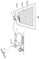
図2に示すように、このコンバインは、圃場において設定された走行経路に沿って自動走行する。このためには、自車位置が必要である。自車位置検出モジュール80には、衛星航法モジュール81と慣性航法モジュール82とが含まれている。衛星航法モジュール81は、人工衛星GSからのGNSS(global navigation satellite system)信号(GPS信号を含む)を受信して、自車位置を算出するための測位データを出力する。慣性航法モジュール82は、ジャイロ加速度センサおよび磁気方位センサを組み込んでおり、瞬時の走行方向を示す位置ベクトルを出力する。慣性航法モジュール82は、衛星航法モジュール81による自車位置算出を補完するために用いられる。慣性航法モジュール82は、衛星航法モジュール81とは別の場所に配置しても良い。
このコンバインによって圃場での収穫作業を行う場合の手順は、以下に説明する通りである。
まず、運転者兼監視者は、コンバインを手動で操作し、図2に示すように、圃場内の外周部分において、圃場の境界線に沿って周回するように収穫走行を行う。これにより既刈地(既作業地)となった領域は、外周領域SAとして設定される。そして、外周領域SAの内側に未刈地(未作業地)のまま残された領域は、作業対象領域CAとして設定される。図2は、外周領域SAと作業対象領域CAの一例を示している。
また、このとき、外周領域SAの幅をある程度広く確保するために、運転者は、コンバインを2~3周走行させる。この走行においては、コンバインが1周する毎に、コンバインの作業幅分だけ外周領域SAの幅が拡大する。最初の、2~3周の走行が終わると、外周領域SAの幅は、コンバインの作業幅の2~3倍程度の幅となる。この周回走行は、予め与えられた圃場外形状データに基づいて自動走行によって行われても良い。
外周領域SAは、作業対象領域CAにおいて収穫走行を行うときに、コンバインが方向転換するためのスペースとして利用される。また、外周領域SAは、収穫走行を一旦終えて、穀粒の排出場所へ移動する際や、燃料の補給場所へ移動する際等の移動用のスペースとしても利用される。
なお、図2に示す運搬車CVは、コンバインから排出された穀粒を収集し、運搬することができる。穀粒排出の際、コンバインは運搬車CVの近傍へ移動した後、穀粒排出装置18によって穀粒を運搬車CVへ排出する。
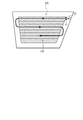
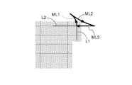
外周領域SAおよび作業対象領域CAが設定されると、図3に示すように、作業対象領域CAにおける走行経路が算定される。算定された走行経路は、作業走行のパターンに基づいて順次設定され、設定された走行経路に沿って、コンバインが自動走行する。なお、このコンバインは、旋回走行のための旋回パターンとして、図3に示すようなU字状の旋回走行経路に沿って方向転換するU旋回パターンと、図4に示すような前後進を繰り返しながら方向転換するα旋回パターンと、図5に示すような後進走行をともなってU旋回パターンよりも狭い領域でU旋回パターンと同様の方向転換をするスイッチバック旋回パターンとを有する。図4のα旋回パターンでは、90°の切り返し旋回走行経路が示されている。この切り返し旋回走行では、その経路は、移行元走行経路L1から、前進走行経路ML1、後進走行経路ML2、前進走行経路ML3を経て、移行先走行経路L2に至る。図5のスイッチバック旋回パターンでは直線往復走行での経路移行で用いられる180°の切り返し旋回走行が示されている。この切り返し旋回走行でも同様に、その経路は、移行元走行経路L1から、前進走行経路ML4、後進走行経路ML5、前進走行経路ML6を経て、移行先走行経路L2に至る。このような後進を含む旋回走行は、穀粒タンク14が満杯になって、作業対象領域CAの走行経路から離脱したコンバインが、運搬車CVに対して位置合わせする時などにも行われる。
図6に、本発明による自動操舵システムを利用するコンバインの制御系が示されている。コンバインの制御系は、多数のECUと呼ばれる電子制御ユニットからなる制御ユニット5、および、この制御ユニット5との間で車載LANなどの配線網を通じて信号通信(データ通信)を行う各種入出力機器から構成されている。
報知デバイス62は、運転者等に作業走行状態や種々の警告を報知するためのデバイスであり、ブザー、ランプ、スピーカ、ディスプレイなどである。通信部66は、このコンバインの制御系が、通信端末2との間で、あるいは、遠隔地に設置されている管理コンピュータとの間でデータ交換するために用いられる。通信端末2には、圃場に立っている監視者、またはコンバイン乗り込んでいる運転者兼監視者が操作するタブレットコンピュータ、自宅や管理事務所に設置されているコンピュータなども含まれる。制御ユニット5は、この制御系の中核要素であり、複数のECUの集合体として示されている。自車位置検出モジュール80からの信号は、車載LANを通じて制御ユニット5に入力される。
制御ユニット5は、入出力インタフェースとして、出力処理部503と入力処理部502とを備えている。出力処理部503は、機器ドライバ65を介して種々の動作機器70と接続している。動作機器70として、走行関係の機器である走行機器群71と作業関係の機器である作業機器群72とがある。走行機器群71には、例えば、操舵機器710、エンジン機器、変速機器、制動機器などが含まれている。作業機器群72には、収穫部H(図1参照)、脱穀装置13(図1参照)、搬送装置16(図1参照)、穀粒排出装置18(図1参照)における動力制御機器などが含まれている。
入力処理部502には、走行状態センサ群63、作業状態センサ群64、走行操作ユニット90、などが接続されている。走行状態センサ群63には、エンジン回転数センサ、オーバーヒート検出センサ、ブレーキペダル位置検出センサ、変速位置検出センサ、操舵位置検出センサなどが含まれている。作業状態センサ群64には、収穫作業装置(収穫部H、脱穀装置13、搬送装置16、穀粒排出装置18)の駆動状態を検出するセンサ、穀稈や穀粒の状態を検出するセンサなどが含まれている。
走行操作ユニット90は、運転者によって手動操作され、その操作信号が制御ユニット5に入力される操作具の総称である。走行操作ユニット90には、主変速操作具91、操舵操作具92、モード操作具93、自動開始操作具94、などが含まれている。手動走行モードでは、操舵操作具92を中立位置から左右に揺動操作することにより、左のクローラ機構のクローラ速度と右のクローラ機構のクローラ速度とが調整され、車体10(以下、いずれも図1参照)の向きが変更される。本発明では、車体10が進行する向きを変更する操作を操舵と総称し、車輪等の向きを変えることだけでなく、左右のクローラの速度を調整することも操舵すると称す。モード操作具93は、自動運転が行われる自動走行モードと手動運転が行われる手動走行モードとを切り替えるための指令を制御ユニット5に与える機能を有する。自動開始操作具94は、自動走行を開始するための最終的な自動開始指令を制御ユニット5に与える機能を有する。なお、モード操作具93による操作とは無関係に、自動走行モードから手動走行モードへの移行が、ソフトウエアによって自動的に行われる場合もある。例えば、自動運転が不可能な状況が発生すると、制御ユニット5は、強制的に自動走行モードから手動走行モードへの移行を実行する。
制御ユニット5には、報知部501、走行制御部51、作業制御部52、走行モード管理部53、走行経路設定部54、自車位置算出部55、車体方位算出部56、位置ずれ量算出部57、方位ずれ量算出部58、基準直線算出部59が備えられている。報知部501は、制御ユニット5の各機能部からの指令等に基づいて報知データを生成し、報知デバイス62に与える。自車位置算出部55は自車位置検出モジュール80から逐次送られてくる測位データに基づいて、予め設定されている車体10の基準点の地図座標(または圃場座標)である自車位置を算出する。つまり、自車位置算出部55は、車体10の基準点の位置を算出する基準点算出部として機能する。この基準点には、後で説明される車体基準点や旋回基準点などが含まれる。車体方位算出部56は、自車位置算出部55で逐次算出される自車位置から、微小時間での走行軌跡を求めて車体10の走行方向での向きを示す車体方位を決定する。また、車体方位算出部56は、慣性航法モジュール82からの出力データに含まれている方位データに基づいて車体方位を決定することも可能である。
走行制御部51は、エンジン制御機能、操舵制御機能、車速制御機能などを有し、走行機器群71に制御信号を与える。作業制御部52は、収穫作業装置(収穫部H(図1参照)、脱穀装置13(図1参照)、搬送装置16(図1参照)、穀粒排出装置18(図1参照)など)の動きを制御するために、作業機器群72に制御信号を与える。
走行制御部51に含まれているずれ方向判定部509は、後述の位置ずれ量算出部57によって算出される位置ずれ量に基づいて、車体10が旋回経路の内側にずれているか、外側にずれているかを判定する。走行制御部51に含まれている操舵制御部510は、位置ずれ量算出部57によって算出される位置ずれ量と、方位ずれ量算出部58によって算出される方位ずれ量との少なくとも一方に基づいて操舵量を算出して、操舵機器710に出力する。つまり、操舵制御部510は、走行経路設定部54によって設定された目標となる走行経路と、自車位置算出部55によって算出された自車位置との間の位置ずれ量と方位ずれ量との少なくとも一方が小さくなるように操舵制御(旋回制御)を行う。この実施形態では、操舵制御部510には、PID制御方式またはPI制御方式が採用される。もちろん、他の制御方式が採用されても良い。このコンバインは自動走行で収穫作業を行う自動運転と手動走行で収穫作業を行う手動運転との両方で走行可能である。このため、走行制御部51には、さらに、手動走行制御部511と自動走行制御部512とが含まれている。なお、自動運転を行う際には、自動走行モードが設定され、手動運転を行うためには手動走行モードが設定される。上述したように、走行モードの切り替えは、走行モード管理部53によって管理される。
なお、走行制御部51の操舵制御部510は、車体10が旋回経路の内側にずれているか、外側にずれているかに応じて、操舵制御の構成を異ならせても良い。例えば、車体10が旋回経路の外側にずれている場合は、位置ずれ量と、方位ずれ量とに基づいて操舵量を算出して、操舵機器710に出力する。また、車体10が旋回経路の内側にずれている場合は、位置ずれ量を考慮せず、方位ずれ量のみに基づいて操舵量を算出して、操舵機器710に出力する。このように制御することにより、操舵方向が逆転して操舵角の変更量が大きくなりすぎ、車体の10走行が不安定になったり、圃場を荒らしたりすることが抑制される。その結果、旋回走行において、簡単な算法で高速に位置ずれ量および方位ずれ量を算出して、正確で適切な操舵制御が可能となる。
自動走行モードが設定されている場合、自動走行制御部512は、操舵制御部510と協働しながら、自動操舵および停止を含む車速変更の制御信号を生成して、走行機器群71を制御する。その際、車速変更に関する制御信号は、前もって設定された車速値に基づいて生成される。
走行経路設定部54は、管理している旋回経路を含む走行経路を順次選択して、走行目標経路として設定する。旋回経路は、実質的には旋回円の円弧である。この旋回円の中心と旋回円の半径とによって、円弧状の旋回経路が規定される。車体10が正確に旋回経路を走行すると仮定した場合、この旋回円の中心が車体10の旋回中心となる。走行経路設定部54で管理される走行経路は、走行経路設定部54が経路算出アルゴリズムによって自ら生成することもできるが、通信端末2や遠隔地の管理コンピュータ等で生成されたものをダウンロードしたものを用いることも可能である。
手動走行モードが選択されている場合、運転者による操作に基づいて、手動走行制御部511が制御信号を生成し、走行機器群71を制御することで、手動運転が実現する。なお、走行経路設定部54によって算出された走行経路は、手動運転であっても、コンバインが当該走行経路に沿って走行するためのガイダンス目的で利用することができる。
位置ずれ量算出部57は、走行経路設定部54によって設定された走行経路と、自車位置算出部55によって算出された自車位置との間の距離である位置ずれを算出する。方位ずれ量算出部58は、走行経路設定部54によって設定された走行経路の延び方向と、車体方位算出部56によって算出された車体方位と、の間の角度差を方位ずれとして算出する。この実施形態では、自車位置算出部55によって算出された自車位置は、ずれのない理想的な旋回走行において、旋回円によって規定される旋回経路の上に乗る点である旋回基準点としている。もちろん、直線走行経路におけるずれのない理想的な走行においても、この旋回基準点は直線走行経路に乗ることになるので、旋回基準点は直線走行経路における車体基準点として用いることができる。その場合、旋回基準点と車体基準点は同一となる。
基準直線算出部59は、基準直線を算出する。基準直線は、旋回走行における、位置ずれ量算出部57による位置ずれ量の算出、および、方位ずれ量算出部58による方位ずれ算出の算出に用いられる。次に、図7を用いて、基準直線と位置ずれ量と方位ずれ量との関係を説明する。
図7,図12は、旋回前の走行経路である旋回前走行経路から旋回先の走行経路である旋回後走行経路へ旋回走行する際に設定された、旋回円Cと車体10との関係を示している。図7に示す例では、旋回前走行経路と旋回後走行経路とは直交関係であり、旋回経路は、旋回円Cの90°円弧である。また、車体10は旋回円Cの外側にずれている。図12に示す例では、旋回前走行経路と旋回後走行経路とは平行関係であり、旋回経路は、旋回円Cの180°円弧である。また、車体10は旋回円Cの内側にずれている。なお、旋回前走行経路と旋回後走行経路との関係は例示であり、いずれの場合も車体10が旋回円Cの内側または外側にずれることが想定される。図7,図12の説明で用いられる符号は、以下のように定義される。Cは旋回円を示す。Pは旋回円Cの中心である。旋回円の中心Pの座標値は(X,Y)であり、走行経路設定部54によって管理されている。Rは旋回円Cの半径である。VPは、車体10の旋回基準点(車体基準点)であり、座標値(x、y)で表される。旋回基準点VPの座標値(x、y)は、自車位置算出部55によって算出される。CLは、車体10の前後方向に延びた中心線である車体中心線である。dは、旋回円の中心Pと旋回基準点VPとの2点間距離である。BLは、旋回円の中心Pと旋回基準点VPとの2点を結ぶ直線であり、この直線が、「基準直線」である。PLは、旋回基準点VPを通って基準直線BLに垂直な直線であり、以下、「方位基準線」と称する。
図7は、旋回走行途中の状態を示しており、車体10は、旋回円Cの外側に位置ずれしていると共に、方位基準線PLに対して右側に車体方位(車体中心線CL)がずれている。また、図12は、旋回走行途中の状態を示しており、車体10は、旋回円Cの内側に位置ずれしていると共に、方位基準線PLに対して左側に車体方位(車体中心線CL)がずれている。基準直線算出部59は、旋回円の中心Pと旋回基準点VPとの2点を結ぶ直線式を求め、基準直線BLを算出する。位置ずれ量算出部57は、旋回円の中心Pと旋回基準点VPとの2点間距離dを算出し、この2点間距離dからRを減算することで位置ずれ量δを算出する。この減算では、正負符号が考慮され、減算値が負であれば、車体10は旋回円Cの内側に位置ずれしていることになり、減算値が正であれば、車体10は旋回円Cの外側に位置ずれしていることになる。ずれ方向判定部509は、位置ずれ量δの正負符号を判定し、車体10が旋回円Cの内側にずれているか外側にずれているかを判定する。方位ずれ量算出部58は、車体中心線CLと方位基準線PLとがなす角度(交差角)を方位ずれ量θとして算出する。方位ずれ量θが正の値であれば、車体10は走行方向で右方向にずれていることになり、方位ずれ量θが負の値であれば、車体10は走行方向で左方向にずれていることになる。このようにして、微小走行単位で、位置ずれ量δと方位ずれ量θを算出して、操舵制御部510に与えることで、PIDまたはPI制御に基づいた操舵量が出力される。
図6,図7,図12を参照しながら、図13を用いて、旋回走行における操舵量の算出手順の一例を以下に示す。
(1)自車位置算出部55から車体10の自車位置である旋回基準点VPの座標値(x、y)が取得される(図13のステップ#1)。
(2)基準直線BLの直線式が求められる(図13のステップ#2)。
(3)旋回円Cの中心Pと旋回基準点VPとの間の長さである2点間距離dが求められる(図13のステップ#3)。
(4)2点間距離dから旋回円Cの半径Rが減算されて、その値が位置ずれ量δとされる(図13のステップ#4)。
(5)車体方位算出部56からの車体方位に基づいて車体中心線CLの直線式が求められる(図13のステップ#5)。
(6)基準直線BLの直線式に基づいて、基準直線BLに垂直な方位基準線PLが算出され、車体中心線CLと方位基準線PLとがなす角度(交差角)が方位ずれ量θとして算出される(図13のステップ#6)。
(7)位置ずれ量δの正負符号から車体10が旋回円Cの内側にずれているか外側にずれているかが判定される(図13のステップ#7)。
(8)外側にずれている場合、位置ずれ量δと方位ずれ量θとから操舵量が算出される(図13のステップ#8)。
(9)内側にずれている場合、方位ずれ量θとから操舵量が算出される(図13のステップ#9)。
このように、旋回円Cに対して車体10が内側にずれているか外側にずれているかに応じて、操舵制御を異ならせることにより、状況に適した操舵制御が可能となる。旋回円Cに対して車体10が内側にずれている場合、内向きに旋回している車体10を外向きに旋回させる傾向となり、旋回方向の変位量が多くなり、急激な旋回が行われることになる。このような旋回が行われると、車体10の走行安定性が低下したり、圃場を荒らしたりすることになる。そのため、旋回円Cに対する車体10の位置関係に応じて操舵制御を異ならせることにより、旋回方向の変位量を抑制し、急激な旋回を回避することが可能となる。例えば、旋回円Cに対して車体10が外側にずれている場合には、位置ずれ量δと方位ずれ量θとを用いて操舵制御を行い、旋回円Cに対して車体10が内側にずれている場合には、位置ずれ量δを考慮せず、方位ずれ量θのみを用いて操舵制御を行う。これにより、旋回方向の変位量等を決定するパラメータが削減され、急激な旋回が抑制される。その結果、車体10の走行安定性が低下したり、圃場を荒らしたりすることを抑制できる、適切な操舵制御を行うことが可能となる。
なお、(3)、(4)に代えて、基準直線BLと旋回円Cとの交点が簡単に求められる場合には、求められた交点と旋回基準点VPとの2点間距離を演算することで位置ずれ量δが得られる。また、基準点を通り基準直線に垂直な直線の直線式が簡単に求められる場合には、(6)に変えて、直接、車体中心線CLと基準直線BLとのなす角度(交差角)を求めて、当該角度から90°減算した値を方位ずれ量θとしても良い。
次に、旋回円を用いた自動操舵で旋回走行誤差が生じた場合の対処策を列挙する。
(A)図8は、設定された旋回円C(旋回円Cの半径がRとする)での旋回走行において、旋回終了時に位置ずれ量δが生じている状況を示している。このような旋回ずれが生じた原因として、「旋回開始時において車体10の方位がずれていた」、あるいは、「圃場の滑りなどにより実際の旋回半径が大きくなった」といった複数の原因が考えられるので、決定的な対策を講じることが困難である。この問題を解決するために、旋回開始時および旋回終了時の実際の車体10の位置と方位とから、適正に旋回走行できる適正化旋回円Coが算出される。図8に示すように、旋回開始時の車体10の旋回基準点VPを通って車体中心線CLに垂直な直線K1と、旋回終了時の車体10の旋回基準点VPを通って車体中心線CLに垂直な直線K2との交点を求め、その交点を中心として、旋回開始時の車体10の旋回基準点VPと旋回終了時の車体10の旋回基準点VPとを通る円が適正化旋回円であり、半径Rcを有する。以降の旋回走行では、この適正化旋回円Coを設定することにより、旋回ずれの少ない旋回走行が期待できる。
(A)図8は、設定された旋回円C(旋回円Cの半径がRとする)での旋回走行において、旋回終了時に位置ずれ量δが生じている状況を示している。このような旋回ずれが生じた原因として、「旋回開始時において車体10の方位がずれていた」、あるいは、「圃場の滑りなどにより実際の旋回半径が大きくなった」といった複数の原因が考えられるので、決定的な対策を講じることが困難である。この問題を解決するために、旋回開始時および旋回終了時の実際の車体10の位置と方位とから、適正に旋回走行できる適正化旋回円Coが算出される。図8に示すように、旋回開始時の車体10の旋回基準点VPを通って車体中心線CLに垂直な直線K1と、旋回終了時の車体10の旋回基準点VPを通って車体中心線CLに垂直な直線K2との交点を求め、その交点を中心として、旋回開始時の車体10の旋回基準点VPと旋回終了時の車体10の旋回基準点VPとを通る円が適正化旋回円であり、半径Rcを有する。以降の旋回走行では、この適正化旋回円Coを設定することにより、旋回ずれの少ない旋回走行が期待できる。
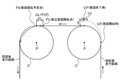
(B)図9は、設定された旋回円Cでの旋回走行で旋回走行誤差が生じた際に、この旋回走行誤差を次の旋回走行で考慮して、より旋回ずれの少ない旋回走行を実現しょうとする方策を示している。ここでは、最初の旋回走行で生じた位置ずれ量δを入力パラメータとして、その位置ずれ量δを解消するために必要な旋回開始点のずらし量ΔLを導出する関数:F(δ)が用いられる。このような関数F(δ)はシミュレーションや実験を通じて作成することができる。関数F(δ)によって導出されたずらし量ΔLで、次の旋回経路の旋回開始予定点Psを修正旋回開始点Pcにずらすことで、次の旋回走行における旋回ずれを少なくすることが期待される。
(C)図10では、図9で示された旋回ずれ改善策に類似する旋回ずれ改善策が示されている。ここでは、最初の旋回走行で生じた位置ずれ量δを入力パラメータとして、その位置ずれ量δを解消するために必要な旋回円の半径の調整量ΔRを導出する関数:G(δ)が用いられる。このような関数G(δ)もシミュレーションや実験を通じて作成することができる。次の旋回走行では、関数G(δ)によって導出された調整量ΔRで調整された半径Rcを有する適正化旋回円Coが旋回円Cに代えて用いられる。その際、旋回円の中心Pも新たな中心P’に移動する。この適正化旋回円Coを用いることで、旋回ずれを少なくすることが期待される。
(D)図11は、設定された旋回円Cでの旋回走行で旋回走行誤差が生じた際に、旋回開始時の車体10の方位ずれ量θsと、旋回終了時の車体10の方位ずれ量θeと、を用いて、次の旋回走行で設定される旋回円を調整して、より旋回ずれの少ない旋回走行を実現しょうとする方策を説明するものである。このため、ここでは、旋回開始時の方位ずれ量θsおよび旋回開始時の方位ずれ量θeを入力パラメータとして、その旋回ずれを解消するために必要な旋回円Cの半径の調整量ΔRを導出する関数:J(θs,θe)が用いられる。このような関数J(θs,θe)もシミュレーションや実験を通じて作成することができる。次の旋回走行では、関数J(θs,θe)によって導出された調整量ΔRで調整された半径Rcを有する適正化旋回円Coを旋回円Cに代えて用いることで、旋回ずれを少なくすることが期待される。
(E)実際のコンバインの旋回軌跡に基づく旋回半径は、穀粒タンク14に貯留されている穀粒の量で変動することが経験的に知られている。このように、貯留穀粒量Vによって生じる旋回走行誤差は、貯留穀粒量Vによって半径を調整される旋回円を設定することで、改善することができる。このためには、貯留穀粒量Vを入力パラメータとして、旋回円の半径の調整量ΔRを導出する関数:H(V)が用いられる。その際、V=0の時の調整量ΔRが0とされ、満量までの調整量が段階的に増加されると好適である。
なお、上述した(A)から(E)の対処策において、旋回ずれが生じた旋回円と次に旋回走行する旋回円が同じ半径を有すると仮定していたが、もし半径が異なる旋回円に対して上述した方策を適用する場合には、予め作成しておいた半径の差を補正する補正係数テーブルを用いることで、そのような旋回円の半径の差による問題を解消することができる。
〔別実施の形態〕(1)操舵量を制御する際に、位置ずれ量δがあらかじめ定められた所定の値(しきい値)δT1より小さい場合、操舵制御部510は、位置ずれ量δを用いずに方位ずれ量θにのみ基づいて操舵量を算出しても良い。これにより、過敏な旋回が抑制され、走行安定性が確保される。
(2)位置ずれ量δがあらかじめ定められた所定の値(しきい値)δT2より大きい場合、操舵制御部510は、方位ずれ量θを用いずに位置ずれ量δにのみ基づいて操舵量を算出しても良い。これにより、位置ずれ量が大きな場合でも、過大な操舵制御が抑制され、急激な旋回が抑制される。
(3)方位ずれ量θがあらかじめ定められた所定の角度(しきい値)θT3より小さい場合、操舵制御部510は、方位ずれ量θを用いずに位置ずれ量δにのみ基づいて操舵量を算出しても良い。これにより、過敏な旋回が抑制され、走行安定性が確保される。
(4)ずれ方向判定部509にて車体10が旋回円Cの内側にずれていると判定された場合、操舵制御部510は、操舵制御に用いられる制御ゲインを、車体10が旋回円Cの外側にずれている場合より小さくし、車体10が旋回円Cの内側にずれていると判定された場合には操舵制御を緩やかに行うようにしても良い。例えば、車体10が旋回円Cの外側にずれている場合の制御ゲインは0.8とされ、車体10が旋回円Cの内側にずれている場合の制御ゲインは0.6とされる。これによって、車体10が旋回円Cの内側にずれている際の、過大な操舵制御が抑制され、急激な旋回が抑制される。
(5)実際のコンバインの旋回は、穀粒タンク7に貯留されている穀粒の量に影響されるため、操舵制御部510は、操舵量を算出する際に、穀粒タンク7に貯留されている穀粒の量(モミ重量)を考慮しても良い。
(6)上述した実施形態では、旋回経路に用いられる旋回円は、圃場に対して走行経路作成アルゴリズムによって生成されるか、あるいは人為的に生成された走行経路に含まれており、走行時において、走行経路設定部54により、順次、目標走行経路として設定される。その際、旋回ずれの発生等に基づいて、旋回円の半径が自動的に変更される例も説明した。これに加えて、人為的に旋回円の半径を変更する構成が採用されても良い。例えば、半径の大きな旋回円(緩旋回用旋回円)が設定される「緩やかモード」と、半径が小さな旋回円(急旋回用旋回円)が選択される「高速モード」といった複数の旋回モードを選択できる人為操作具を設けても良い。「穏やかモード」が選択されると、極力圃場を荒らさない旋回が実現し、「高速モード」が選択されると、旋回走行の時間が短くなり、作業時間が短縮される。なお、実際の車体10の旋回半径は、左右のクローラ機構のクローラ速度の差、あるいは左右の駆動車輪の速度差によって決まってくるが、走行動力をクローラ機構や駆動車輪に伝達する油圧伝動機構における油圧を調整して、旋回半径を調整することも可能である。
(7)上述した実施形態では、自車位置検出モジュール80として、衛星航法モジュール81と慣性航法モジュール82との組み合わせたものが用いられていたが、衛星航法モジュール81だけも良い。また、自車位置や車体方位を、カメラによる撮影画像に基づいて算出する方法が採用されても良い。
(8)図6で示された各機能部は、主に説明目的で区分けされている。実際には、各機能部は他の機能部と統合しても良いし、または複数の機能部に分けても良い。さらに、制御ユニット5に構築されている機能部のうち、走行モード管理部53、走行経路設定部54、位置ずれ量算出部57、方位ずれ量算出部58、基準直線算出部59のうちの全て、または一部が、制御ユニット5に接続可能な携帯型の通信端末2(タブレットコンピュータなど)や管理事務所等に設置されるコンピュータ等に構築され、無線や車載LAN等を経由して制御ユニット5とデータ交換するような構成を採用しても良い。
また、これらの機能部はハードウエアで構成されても良いが、ソフトウエアで構成されても良い。ソフトウエアで構成される場合、制御ユニット5等に設けられる記憶装置(図示せず)にこれらの機能を実現するプログラムが格納され、プログラムは制御ユニット5等が備えるECUやCPU等のプロセッサにより実行される。
なお、上述の実施形態(別実施形態を含む、以下同じ)で開示される構成は、矛盾が生じない限り、他の実施形態で開示される構成と組み合わせて適用することが可能であり、また、本明細書において開示された実施形態は例示であって、本発明の実施形態はこれに限定されず、本発明の目的を逸脱しない範囲内で適宜改変することが可能である。
本発明は、普通型のコンバインだけでなく、自脱型のコンバインにも適用可能である。
また、本発明は、トウモロコシ収穫機、ジャガイモ収穫機、ニンジン収穫機、サトウキビ収穫機等の種々の収穫機、田植機、トラクタなどの圃場作業車にも適用できる。さらには、本発明は、芝刈機や建機などにも適用可能である。
また、本発明は、トウモロコシ収穫機、ジャガイモ収穫機、ニンジン収穫機、サトウキビ収穫機等の種々の収穫機、田植機、トラクタなどの圃場作業車にも適用できる。さらには、本発明は、芝刈機や建機などにも適用可能である。
10 走行車体(作業車)
55 自車位置算出部(基準点算出部)
56 車体方位算出部
57 位置ずれ量算出部
58 方位ずれ量算出部
59 基準直線算出部
509 ずれ判定部
510 操舵制御部
BL 基準直線
C 旋回円
CL 車体中心線(車体方位)
P 中心
PL 方位基準線
VP 旋回基準点(基準点)
δ 位置ずれ量
θ 方位ずれ量
55 自車位置算出部(基準点算出部)
56 車体方位算出部
57 位置ずれ量算出部
58 方位ずれ量算出部
59 基準直線算出部
509 ずれ判定部
510 操舵制御部
BL 基準直線
C 旋回円
CL 車体中心線(車体方位)
P 中心
PL 方位基準線
VP 旋回基準点(基準点)
δ 位置ずれ量
θ 方位ずれ量
Claims (24)
- 設定された旋回円に沿って作業車を自動走行させる自動操舵システムであって、
前記作業車における基準点の位置を算出する基準点算出部と、
前記旋回円の中心と前記基準点とを通る直線を基準直線として算出する基準直線算出部と、
前記作業車の車体の向きを示す車体方位を算出する車体方位算出部と、
前記基準点を通り前記基準直線に垂直な線と前記車体方位との交差角を方位ずれ量として算出する方位ずれ量算出部と、
前記基準点と前記旋回円の外周との位置関係を判定するずれ方向判定部と、
前記基準点が前記旋回円の外周より内側に位置する場合、前記方位ずれ量が小さくなる操舵量を出力する操舵制御部とを備える自動操舵システム。 - 前記操舵制御部は、現在の操舵量と前記方位ずれ量とを入力パラメータとして、PID制御方式またはPI制御方式で前記操舵量を演算して出力する請求項1に記載の自動操舵システム。
- 前記基準直線と前記旋回円との交点から前記基準点までの距離を位置ずれ量として算出する位置ずれ量算出部を備え、
前記基準点が前記旋回円の外周より外側に位置する場合、前記操舵制御部は、前記位置ずれ量と前記方位ずれ量とが小さくなる操舵量を出力する請求項1または2に記載の自動操舵システム。 - 前記操舵制御部は、現在の操舵量と前記位置ずれ量と前記方位ずれ量とを入力パラメータとして、PID制御方式またはPI制御方式で前記操舵量を演算して出力する請求項3に記載の自動操舵システム。
- 前記PID制御方式および前記PI制御方式における制御ゲインは、前記基準点が前記旋回円の外周より外側に位置する場合の方が、前記基準点が前記旋回円の外周より内側に位置する場合より大きい請求項4に記載の自動操舵システム。
- 前記位置ずれ量が所定の値より大きい場合、前記方位ずれ量を入力パラメータから除外する請求項4または5に記載の自動操舵システム。
- 前記方位ずれ量が所定の角度より小さい場合、前記方位ずれ量を入力パラメータから除外する請求項4から6のいずれか一項に記載の自動操舵システム。
- 前記旋回円として、急旋回用旋回円と、前記急旋回用旋回円より半径が大きい緩旋回用旋回円とが選択可能に用意されている請求項1から7のいずれか一項に記載の自動操舵システム。
- 設定された旋回円に沿って作業車を自動走行させる自動操舵方法であって、
前記作業車における基準点の位置を算出する工程と、
前記旋回円の中心と前記基準点とを通る直線を基準直線として算出する工程と、
前記作業車の車体の向きを示す車体方位を算出する工程と、
前記基準点を通り前記基準直線に垂直な線と前記車体方位との交差角を方位ずれ量として算出する工程と、
前記基準点と前記旋回円の外周との位置関係を判定する工程と、
前記基準点が前記旋回円の外周より内側に位置する場合、前記方位ずれ量が小さくなる操舵量を出力する工程とを備える自動操舵方法。 - 出力される前記操舵量は、現在の操舵量と前記方位ずれ量とを入力パラメータとして、PID制御方式またはPI制御方式で演算される請求項9に記載の自動操舵方法。
- 前記基準直線と前記旋回円との交点から前記基準点までの距離を位置ずれ量として算出する工程を備え、
前記基準点が前記旋回円の外周より外側に位置する場合、出力される前記操舵量は、前記位置ずれ量と前記方位ずれ量とが小さくなる操舵量である請求項9または10に記載の自動操舵方法。 - 出力される前記操舵量は、現在の操舵量と前記位置ずれ量と前記方位ずれ量とを入力パラメータとして、PID制御方式またはPI制御方式で演算される請求項11に記載の自動操舵方法。
- 前記PID制御方式および前記PI制御方式における制御ゲインは、前記基準点が前記旋回円の外周より外側に位置する場合の方が、前記基準点が前記旋回円の外周より内側に位置する場合より大きくされる請求項12に記載の自動操舵方法。
- 前記位置ずれ量が所定の値より大きい場合、前記方位ずれ量が入力パラメータから除外される請求項12または13に記載の自動操舵方法。
- 前記方位ずれ量が所定の角度より小さい場合、前記方位ずれ量が入力パラメータから除外される請求項12から14のいずれか一項に記載の自動操舵方法。
- 前記旋回円として、急旋回用旋回円と、前記急旋回用旋回円より半径が大きい緩旋回用旋回円とが選択可能に用意されている請求項9から15のいずれか一項に記載の自動操舵方法。
- 設定された旋回円に沿って作業車を自動走行させる自動操舵プログラムであって、
前記作業車における基準点の位置を算出する手順と、
前記旋回円の中心と前記基準点とを通る直線を基準直線として算出する手順と、
前記作業車の車体の向きを示す車体方位を算出する手順と、
前記基準点を通り前記基準直線に垂直な線と前記車体方位との交差角を方位ずれ量として算出する手順と、
前記基準点と前記旋回円の外周との位置関係を判定する手順と、
前記基準点が前記旋回円の外周より内側に位置する場合、前記方位ずれ量が小さくなる操舵量を出力する手順とをコンピュータに実行させるための自動操舵プログラム。 - 出力される前記操舵量は、現在の操舵量と前記方位ずれ量とを入力パラメータとして、PID制御方式またはPI制御方式で演算される請求項17に記載の自動操舵プログラム。
- 前記基準直線と前記旋回円との交点から前記基準点までの距離を位置ずれ量として算出する手順をコンピュータに実行させ、
前記基準点が前記旋回円の外周より外側に位置する場合、出力される前記操舵量は、前記位置ずれ量と前記方位ずれ量とが小さくなる操舵量である請求項17または18に記載の自動操舵プログラム。 - 出力される前記操舵量は、現在の操舵量と前記位置ずれ量と前記方位ずれ量とを入力パラメータとして、PID制御方式またはPI制御方式で演算される請求項19に記載の自動操舵プログラム。
- 前記PID制御方式および前記PI制御方式における制御ゲインは、前記基準点が前記旋回円の外周より外側に位置する場合の方が、前記基準点が前記旋回円の外周より内側に位置する場合より大きくされる請求項20に記載の自動操舵プログラム。
- 前記位置ずれ量が所定の値より大きい場合、前記方位ずれ量が入力パラメータから除外される請求項20または21に記載の自動操舵プログラム。
- 前記方位ずれ量が所定の角度より小さい場合、前記方位ずれ量が入力パラメータから除外される請求項20から22のいずれか一項に記載の自動操舵プログラム。
- 前記旋回円として、急旋回用旋回円と、前記急旋回用旋回円より半径が大きい緩旋回用旋回円とが選択可能に用意されている請求項17から23のいずれか一項に記載の自動操舵プログラム。
Priority Applications (2)
| Application Number | Priority Date | Filing Date | Title |
|---|---|---|---|
| CN201980074612.6A CN113015427B (zh) | 2018-11-30 | 2019-11-27 | 自动转向系统、自动转向方法以及自动转向程序 |
| KR1020217013340A KR102796554B1 (ko) | 2018-11-30 | 2019-11-27 | 자동 조타 시스템, 자동 조타 방법 및 자동 조타 프로그램 |
Applications Claiming Priority (2)
| Application Number | Priority Date | Filing Date | Title |
|---|---|---|---|
| JP2018-225375 | 2018-11-30 | ||
| JP2018225375A JP7042732B2 (ja) | 2018-11-30 | 2018-11-30 | 自動操舵システムおよび自動操舵方法 |
Publications (1)
| Publication Number | Publication Date |
|---|---|
| WO2020111088A1 true WO2020111088A1 (ja) | 2020-06-04 |
Family
ID=70853727
Family Applications (1)
| Application Number | Title | Priority Date | Filing Date |
|---|---|---|---|
| PCT/JP2019/046267 Ceased WO2020111088A1 (ja) | 2018-11-30 | 2019-11-27 | 自動操舵システム、自動操舵方法および自動操舵プログラム |
Country Status (4)
| Country | Link |
|---|---|
| JP (1) | JP7042732B2 (ja) |
| KR (1) | KR102796554B1 (ja) |
| CN (1) | CN113015427B (ja) |
| WO (1) | WO2020111088A1 (ja) |
Cited By (4)
| Publication number | Priority date | Publication date | Assignee | Title |
|---|---|---|---|---|
| EP4151063A1 (en) * | 2021-09-16 | 2023-03-22 | Yanmar Holdings Co., Ltd. | Automatic traveling method, work vehicle, and automatic traveling system |
| JP2023128168A (ja) * | 2022-03-03 | 2023-09-14 | 国立研究開発法人農業・食品産業技術総合研究機構 | 旋回制御装置及び旋回制御方法 |
| JP2023128170A (ja) * | 2022-03-03 | 2023-09-14 | 国立研究開発法人農業・食品産業技術総合研究機構 | 旋回制御装置及び旋回制御方法 |
| US12485896B2 (en) | 2023-08-15 | 2025-12-02 | Torc Robotics, Inc. | Optimization function for turn planning |
Families Citing this family (4)
| Publication number | Priority date | Publication date | Assignee | Title |
|---|---|---|---|---|
| EP4656026A3 (en) * | 2020-03-02 | 2025-12-17 | Raven Industries, Inc. | Guidance systems and methods |
| JP7662492B2 (ja) | 2021-11-17 | 2025-04-15 | 株式会社クボタ | 作業車両、および作業車両の制御装置 |
| JP7476870B2 (ja) * | 2021-11-25 | 2024-05-01 | 井関農機株式会社 | 作業車両 |
| JP7837818B2 (ja) * | 2022-07-01 | 2026-03-31 | ヤンマーホールディングス株式会社 | 自動走行方法、作業車両及び自動走行システム |
Citations (3)
| Publication number | Priority date | Publication date | Assignee | Title |
|---|---|---|---|---|
| JP2002182746A (ja) * | 2000-12-19 | 2002-06-26 | Yanmar Agricult Equip Co Ltd | 農業用作業車 |
| JP2011123822A (ja) * | 2009-12-14 | 2011-06-23 | Tsubakimoto Chain Co | 搬送車及びプログラム |
| WO2019123923A1 (ja) * | 2017-12-18 | 2019-06-27 | 株式会社クボタ | 自動操舵システムおよび自動操舵方法 |
Family Cites Families (6)
| Publication number | Priority date | Publication date | Assignee | Title |
|---|---|---|---|---|
| JP2002358122A (ja) | 2001-05-31 | 2002-12-13 | Yanmar Agricult Equip Co Ltd | 農業用作業車 |
| US7256388B2 (en) * | 2005-02-04 | 2007-08-14 | Novariant, Inc. | System and method for interactive selection of agricultural vehicle guide paths through a graphical user interface other than moving the vehicle |
| JP5265808B2 (ja) * | 2010-03-04 | 2013-08-14 | 本田技研工業株式会社 | 車両の旋回制御装置 |
| EP2944547B1 (en) * | 2013-01-10 | 2018-03-28 | Nissan Motor Company, Limited | In-lane drive assist device |
| JP6502221B2 (ja) * | 2015-09-14 | 2019-04-17 | 株式会社クボタ | 作業車支援システム |
| JP6552420B2 (ja) * | 2016-01-13 | 2019-07-31 | 株式会社クボタ | 作業車 |
-
2018
- 2018-11-30 JP JP2018225375A patent/JP7042732B2/ja active Active
-
2019
- 2019-11-27 CN CN201980074612.6A patent/CN113015427B/zh active Active
- 2019-11-27 KR KR1020217013340A patent/KR102796554B1/ko active Active
- 2019-11-27 WO PCT/JP2019/046267 patent/WO2020111088A1/ja not_active Ceased
Patent Citations (3)
| Publication number | Priority date | Publication date | Assignee | Title |
|---|---|---|---|---|
| JP2002182746A (ja) * | 2000-12-19 | 2002-06-26 | Yanmar Agricult Equip Co Ltd | 農業用作業車 |
| JP2011123822A (ja) * | 2009-12-14 | 2011-06-23 | Tsubakimoto Chain Co | 搬送車及びプログラム |
| WO2019123923A1 (ja) * | 2017-12-18 | 2019-06-27 | 株式会社クボタ | 自動操舵システムおよび自動操舵方法 |
Cited By (6)
| Publication number | Priority date | Publication date | Assignee | Title |
|---|---|---|---|---|
| EP4151063A1 (en) * | 2021-09-16 | 2023-03-22 | Yanmar Holdings Co., Ltd. | Automatic traveling method, work vehicle, and automatic traveling system |
| JP2023128168A (ja) * | 2022-03-03 | 2023-09-14 | 国立研究開発法人農業・食品産業技術総合研究機構 | 旋回制御装置及び旋回制御方法 |
| JP2023128170A (ja) * | 2022-03-03 | 2023-09-14 | 国立研究開発法人農業・食品産業技術総合研究機構 | 旋回制御装置及び旋回制御方法 |
| JP7704430B2 (ja) | 2022-03-03 | 2025-07-08 | 国立研究開発法人農業・食品産業技術総合研究機構 | 旋回制御装置及び旋回制御方法 |
| JP7704429B2 (ja) | 2022-03-03 | 2025-07-08 | 国立研究開発法人農業・食品産業技術総合研究機構 | 旋回制御装置及び旋回制御方法 |
| US12485896B2 (en) | 2023-08-15 | 2025-12-02 | Torc Robotics, Inc. | Optimization function for turn planning |
Also Published As
| Publication number | Publication date |
|---|---|
| KR102796554B1 (ko) | 2025-04-18 |
| JP2020087308A (ja) | 2020-06-04 |
| CN113015427A (zh) | 2021-06-22 |
| KR20210096079A (ko) | 2021-08-04 |
| JP7042732B2 (ja) | 2022-03-28 |
| CN113015427B (zh) | 2022-10-28 |
Similar Documents
| Publication | Publication Date | Title |
|---|---|---|
| KR102871790B1 (ko) | 자동 조타 시스템 및 자동 조타 방법 | |
| WO2020111088A1 (ja) | 自動操舵システム、自動操舵方法および自動操舵プログラム | |
| KR102939506B1 (ko) | 자동 조타 시스템 및 수확기, 자동 조타 방법, 자동 조타 프로그램, 기록 매체 | |
| JP6991058B2 (ja) | 自動操舵システム | |
| JP7345534B2 (ja) | 自動走行システム | |
| WO2020031473A1 (ja) | 外形形状算出システム、外形形状算出方法、外形形状算出プログラム、及び外形形状算出プログラムが記録されている記録媒体と、圃場マップ作成システム、圃場マップ作成プログラム、圃場マップ作成プログラムが記録されている記録媒体、及び圃場マップ作成方法 | |
| CN113039501B (zh) | 自动行驶控制系统、记录有自动行驶控制程序的记录介质、自动行驶控制方法 | |
| JP6994831B2 (ja) | 自動操舵システム | |
| JP2022016479A5 (ja) | ||
| JP6983734B2 (ja) | 収穫機 | |
| JP7117985B2 (ja) | 自動走行制御システム | |
| JP6745784B2 (ja) | 作業車 | |
| JP2020028224A (ja) | 圃場マップ作成システム | |
| JP7206099B2 (ja) | 自動走行作業車のための制御装置 | |
| JP2022011847A (ja) | 農作業機及び農作業機の自動走行方法 | |
| JP6976156B2 (ja) | 作業車の自動操舵システム | |
| JP2020031593A (ja) | 圃場作業車のための自動操舵システム | |
| JP6952597B2 (ja) | 作業車 | |
| JP2023006430A (ja) | 作業車および自動走行制御システム |
Legal Events
| Date | Code | Title | Description |
|---|---|---|---|
| 121 | Ep: the epo has been informed by wipo that ep was designated in this application |
Ref document number: 19890570 Country of ref document: EP Kind code of ref document: A1 |
|
| NENP | Non-entry into the national phase |
Ref country code: DE |
|
| 122 | Ep: pct application non-entry in european phase |
Ref document number: 19890570 Country of ref document: EP Kind code of ref document: A1 |