WO2020110798A1 - 伝送装置及び伝送方法 - Google Patents
伝送装置及び伝送方法 Download PDFInfo
- Publication number
- WO2020110798A1 WO2020110798A1 PCT/JP2019/045056 JP2019045056W WO2020110798A1 WO 2020110798 A1 WO2020110798 A1 WO 2020110798A1 JP 2019045056 W JP2019045056 W JP 2019045056W WO 2020110798 A1 WO2020110798 A1 WO 2020110798A1
- Authority
- WO
- WIPO (PCT)
- Prior art keywords
- line
- client
- unit
- interface
- signal
- Prior art date
- Legal status (The legal status is an assumption and is not a legal conclusion. Google has not performed a legal analysis and makes no representation as to the accuracy of the status listed.)
- Ceased
Links
Images



Classifications
-
- H—ELECTRICITY
- H04—ELECTRIC COMMUNICATION TECHNIQUE
- H04L—TRANSMISSION OF DIGITAL INFORMATION, e.g. TELEGRAPHIC COMMUNICATION
- H04L1/00—Arrangements for detecting or preventing errors in the information received
- H04L1/22—Arrangements for detecting or preventing errors in the information received using redundant apparatus to increase reliability
-
- H—ELECTRICITY
- H04—ELECTRIC COMMUNICATION TECHNIQUE
- H04L—TRANSMISSION OF DIGITAL INFORMATION, e.g. TELEGRAPHIC COMMUNICATION
- H04L1/00—Arrangements for detecting or preventing errors in the information received
- H04L1/004—Arrangements for detecting or preventing errors in the information received by using forward error control
- H04L1/0041—Arrangements at the transmitter end
-
- H—ELECTRICITY
- H04—ELECTRIC COMMUNICATION TECHNIQUE
- H04L—TRANSMISSION OF DIGITAL INFORMATION, e.g. TELEGRAPHIC COMMUNICATION
- H04L1/00—Arrangements for detecting or preventing errors in the information received
- H04L1/004—Arrangements for detecting or preventing errors in the information received by using forward error control
- H04L1/0045—Arrangements at the receiver end
-
- H—ELECTRICITY
- H04—ELECTRIC COMMUNICATION TECHNIQUE
- H04L—TRANSMISSION OF DIGITAL INFORMATION, e.g. TELEGRAPHIC COMMUNICATION
- H04L1/00—Arrangements for detecting or preventing errors in the information received
- H04L1/12—Arrangements for detecting or preventing errors in the information received by using return channel
- H04L1/16—Arrangements for detecting or preventing errors in the information received by using return channel in which the return channel carries supervisory signals, e.g. repetition request signals
- H04L1/1607—Details of the supervisory signal
Definitions
- the present invention relates to a transmission device and a transmission method.
- the transmission device is a device in which the redundancy of the client side line (client redundancy) such as LAG redundancy or SDH redundancy and the redundancy of the line side line (line redundancy) in which non-instantaneous switching is performed are used together. It is necessary.
- a conventional transmission device performs a client redundancy termination process, maps a client signal to an ODU (Optical Channel Data Unit), and then performs line redundancy.
- ODU Optical Channel Data Unit
- an object of the present invention is to provide a technique capable of further increasing the reliability of a transmission device.
- communication is performed with a communication device provided in a first network
- communication is performed with a redundant first communication device and communication device provided in a second network
- redundancy is performed.
- a second communication device each of the second communication devices includes a first end that is an end of a redundant communication path of the first communication device, and the first communication device includes the second communication device.
- the transmission device includes a second end that is an end of a redundant communication path of the device.
- One aspect of the present invention is the transmission device described above, wherein the first end portion transmits the reception signal received by the second communication device toward the first communication device, and the second end portion. Selects any one of the received signals transmitted from the second communication device.
- One aspect of the present invention is the above transmission device, wherein redundancy information indicating a redundancy state of the second communication device is acquired from the second communication device, and the second end portion is acquired based on the redundancy information. And a redundant controller for controlling the received signal selected by.
- the 1 aspect of this invention is the said transmission apparatus, Comprising: The said 2nd edge part transmits the reception signal received by the said 1st communication apparatus toward the said 2nd communication apparatus, The 1st edge part Selects any one of the received signals transmitted from the first communication device.
- One aspect of the present invention is the transmission device described above, wherein the first end is based on abnormality information indicating a network abnormality or a control signal input by a user and controlling which received signal is selected. Then, any one of the received signals is selected.
- One aspect of the present invention is the transmission device described above, wherein one or more of the first communication device or the second communication device is an interface card.
- a transmission device duplicates a signal received by a redundant second communication device at a first end that is an end of a communication path of a redundant first communication device, A transmission step of transmitting to the first communication device, and a transmission device, among the signals transmitted from the second communication device, at a second end that is an end of a redundant communication path of the second communication device. A selection step of selecting any one of them, and a transmission method in which the transmission device transmits the selected signal to the first network.
- the present invention makes it possible to further increase the reliability of the transmission device.
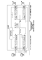
- FIG. 6 is a flowchart showing a flow of processing in which the transmission device 100a of the first embodiment transmits from a line side line to a client side line. It is a functional block diagram of transmission device 100c which performs communication from the client side to the line side of a 2nd embodiment. It is a functional block diagram of the transmission device of a prior art.
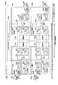
- FIG. 1 is a functional block diagram of a transmission device 100 that performs communication from the client side to the line side according to the first embodiment.
- the transmission device 100 includes a CPU (Central Processing Unit), a memory, an auxiliary storage device, and the like connected by a bus.
- the transmission device 100 represents a configuration for transmitting a signal received from a client side line to a line side line.
- the transmission device 100 includes a client signal receiving unit 110, a client signal receiving unit 110a, a line signal transmitting unit 120, a line signal transmitting unit 120a, and a main board 130.
- the client signal receiving unit 110 is connected to the active communication line on the client side.
- the client signal receiving unit 110 is an interface card.
- the client signal receiving unit 110 includes a receiving unit 111, an Rx interface 112, a client redundant OH (Over Head) extracting unit 113, an ODU mapping unit 114, a line BRG 115, a Chip interface 116, and a Chip interface 117.
- the active communication line on the client side may have a communication speed of 100 G, for example, but is not limited to 100 G.
- the client signal receiving unit 110 is an aspect of the second communication device.
- the receiving unit 111 receives the received signal.
- the receiver 111 photoelectrically converts the received signal.
- the receiver 111 transmits the photoelectrically converted reception signal to the Rx interface 112.
- the received signal is a 100 GE (Gigabit Ethernet) signal that is made redundant by an L2 switch or the like.
- the receiving unit 111 is, for example, an interface such as the QSFP 28, but is not limited to this.
- the receiving unit 111 may use any interface according to the speed or type of the communication line.
- the Rx interface 112 restores the photoelectrically converted received signal to the 100GE format.
- the Rx interface 112 transmits the restored reception signal to the client redundancy OH extraction unit 113.
- the client redundant OH extraction unit 113 extracts a LACPDU (Link Aggregation Control Protocol Data Unit) from the received signal.
- the client redundant OH extraction unit 113 transmits the extracted LACPDU to the redundant controller 135.
- the client redundancy OH extraction unit 113 transmits the reception signal after the LACPDU is extracted to the ODU mapping unit 114.
- LACPDU is an aspect of redundant information.
- the redundancy information represents the redundancy status of the plurality of client signal receiving units.
- the redundant state is, for example, information indicating which client signal receiving unit is made redundant.
- the ODU mapping unit 114 maps the received signal received to the ODU4.
- the ODU mapping unit 114 adds ODU overhead to the mapped ODU4.
- the ODU mapping unit 114 transmits the ODU4 to which the ODU overhead is added to the line BRG 115.
- the line BRG 115 is the beginning of the line redundant section.
- the line redundant section is a section that represents a redundant configuration of the line signal transmitting unit 120 and the line signal transmitting unit 120a.
- the line BRG 115 transmits the received ODU4 to the line-side 0-system line and the line-side 1-system line in order to switch without interruption. Specifically, the line BRG115 copies ODU4 to ODU4-1 and ODU4-2.
- the line BRG 115 sends the duplicated ODU 4-1 to the Chip interface 116.
- the line BRG 115 sends the duplicated ODU4-2 to the Chip interface 117.
- the line BRG 115 is one mode of the first end portion.
- the Chip interface 116 converts the received ODU4-1 into a format that can be transferred between Chips.
- the Chip interface 116 transmits the converted ODU4-1 to the connection unit 131.
- the Chip interface 117 converts the received ODU4-2 into a format that can be transferred between Chips.
- the Chip interface 117 sends the converted ODU4-2 to the connection unit 131.
- the client signal receiving unit 110a is connected to the backup communication line on the client side.
- the client signal receiving unit 110a is an interface card.
- the client signal receiving unit 110a includes a receiving unit 111a, an Rx interface 112a, a client redundant OH extracting unit 113a, an ODU mapping unit 114a, a line BRG 115a, a Chip interface 116a, and a Chip interface 117a.
- the backup communication line on the client side may have a communication speed of 100 G, for example, but is not limited to 100 G.
- the client signal receiving unit 110a is an aspect of the second communication device.
- the backup communication line on the client side is made redundant with the active communication line by a protocol such as LACP.
- the receiving unit 111a, the Rx interface 112a, the client redundant OH extracting unit 113a, and the ODU mapping unit 114a perform the same operations as the receiving unit 111, the Rx interface 112, the client redundant OH extracting unit 113, and the ODU mapping unit 114.
- the description is omitted.
- the line BRG 115a is the beginning of the line redundant section.
- the line redundant section is a section that represents a redundant configuration of the line signal transmitting unit 120 and the line signal transmitting unit 120a.
- the line BRG 115a transmits the received ODU4 to the line 0 system line and the line side 1 system line in order to switch without interruption. Specifically, the line BRG 115a copies ODU4 to ODU4-3 and ODU4-4.
- the line BRG 115a sends the duplicated ODU4-3 to the Chip interface 116a.
- the line BRG 115a sends the duplicated ODU4-4 to the Chip interface 117a.
- the line BRG 115a is one mode of the first end portion.
- the Chip interface 116a converts the received ODU4-3 into a format that can be transferred between Chips.
- the Chip interface 116a transmits the converted ODU4-3 to the connection unit 132.
- the Chip interface 117a converts the received ODU4-4 into a format that can be transferred between Chips.
- the Chip interface 117a transmits the converted ODU4-4 to the connection unit 132.
- the line signal transmission unit 120 is connected to the 0-system communication line on the line side.
- the line signal transmitter 120 is an interface card.
- the line signal transmission unit 120 includes a Chip interface 121, a Chip interface 122, a client selector 123, an OH addition unit 124, a Tx interface 125, and a transmission unit 126.
- the line signal transmitter 120 is an aspect of the first communication device.
- the first communication device communicates with a communication device provided in the first network.
- the Chip interface 121 receives the ODU4-1 transmitted from the Chip interface 116.
- the Chip interface 121 restores the ODU4-1 converted into the format that can be transferred between Chips to the format before the conversion.
- the Chip interface 121 transmits the restored ODU4-1 to the client selector 123.
- the Chip interface 122 receives the ODU4-3 transmitted from the Chip interface 116a.
- the Chip interface 122 restores the ODU4-3 converted into the format that can be transferred between Chips to the format before the conversion.
- the Chip interface 122 sends the restored ODU4-3 to the client selector 123.
- the client selector 123 is the end of the client redundant section.
- the client redundant section is a section representing a redundant configuration of the client signal receiving unit 110 and the client signal receiving unit 110a.
- the client selector 123 selects either ODU4-1 or ODU4-3 based on the control determined by the redundant controller 135. Hereinafter, the client selector 123 will be described as selecting the ODU 4-1.
- the client selector 123 sends the selected ODU 4-1 to the OH addition unit 124.
- the client selector 123 is an aspect of the second end portion.
- the OH adding unit 124 inserts the OTU4 overhead into the selected ODU4-1.
- the OH addition unit 124 transmits the OTU4-1 to which the OTU4 overhead is added to the Tx interface 125.
- the Tx interface 125 performs FEC (Forward Error Correction) encoding on the OTU 4-1.
- the Tx interface 125 converts the FEC-encoded OTU4-1 into an OTL (Optical Channel Transport Lane) 4.4 interface.
- OTL4.4 is OTU4 divided into four physical lanes.
- the Tx interface 125 transmits the converted OTU4-1 to the transmission unit 126.
- the transmitting unit 126 electro-optically converts the input signal (OTU4-1).
- the transmission unit 126 transmits the converted OTU4-1 to the outside of the transmission device 100.
- the transmission unit 126 is, for example, an interface such as the QSFP 28, but is not limited to this.
- the transmission unit 126 may use an interface according to the speed of the communication line.
- the line signal transmission unit 120a is connected to the 1-system communication line on the line side.
- the line signal transmitter 120a is an interface card.
- the line signal transmission unit 120a includes a Chip interface 121a, a Chip interface 122a, a client selector 123a, an OH addition unit 124a, a Tx interface 125a, and a transmission unit 126a.
- the line signal transmitter 120a is an aspect of the first communication device.
- the 0-system communication line on the line side and the 1-system communication line on the line side are made redundant by switching without interruption.
- the OH addition unit 124a, the Tx interface 125a, and the transmission unit 126a perform the same operations as the OH addition unit 124, the Tx interface 125, and the transmission unit 126, and thus the description thereof will be omitted.
- the Chip interface 121a receives the ODU4-2 transmitted from the Chip interface 117.
- the Chip interface 121a restores the ODU4-2 converted into the format that can be transferred between Chips to the format before the conversion.
- the Chip interface 121a sends the restored ODU4-2 to the client selector 123a.
- the Chip interface 122a receives the ODU4-4 transmitted from the Chip interface 117a.
- the Chip interface 122a restores the ODU4-4 converted into the format that can be transferred between Chips to the format before the conversion.
- the Chip interface 122a sends the restored ODU4-4 to the client selector 123a.
- the client selector 123a is the end of the client redundant section.
- the client selector 123a selects either ODU4-2 or ODU4-4 based on the control determined by the redundant controller 135.
- the client selector 123a will be described as selecting the ODU4-2.
- the client selector 123a transmits the selected ODU4-2 to the OH adding unit 124a.
- the client selector 123a is an aspect of the second end portion.
- the main board 130 includes a connection unit 131, a connection unit 132, a connection unit 133, a connection unit 134, and a redundant controller 135.
- the connection unit 131 is a network interface configured such that an interface card can be attached and detached.
- the connection unit 131 communicatively connects the interface card connected to the connection unit 131 and the interface card connected to the connection unit 133 or the connection unit 134.
- the connection unit 131 connects the client signal reception unit 110.
- connection unit 132 is a network interface in which an interface card is detachably attached.
- the connection unit 132 communicably connects the interface card connected to the connection unit 132 and the interface card connected to the connection unit 133 or the connection unit 134.
- the connection unit 132 connects the client signal reception unit 110a.
- connection unit 133 is a network interface configured such that an interface card can be attached and detached.
- the connection unit 133 communicatively connects the interface card connected to the connection unit 133 and the interface card connected to the connection unit 131 or the connection unit 132.
- the connection unit 133 connects the line signal transmission unit 120.
- connection unit 134 is a network interface configured such that an interface card can be attached and detached.
- the connection unit 134 communicably connects the interface card connected to the connection unit 134 and the interface card connected to the connection unit 131 or the connection unit 132.
- the connection unit 134 connects the line signal transmission unit 120a.
- the redundant controller 135 determines the ODU4 selected by the client selector 123 based on the LACPDU. In the first embodiment, the redundancy controller 135 determines which of the ODU4-1 and ODU4-3 is selected by the client selector 123 based on the LACPDU transmitted by the client redundancy OH extraction unit 113. .. The redundant controller 135 sends the determination result to the client selector 123. In the first embodiment, the redundancy controller 135 determines which of the ODU4-2 or ODU4-4 is selected by the client selector 123a based on the LACPDU transmitted by the client redundancy OH extraction unit 113a. .. The redundant controller 135 sends the determination result to the client selector 123a.
- the section from the receiving section 111 of the client signal receiving section 110 and the receiving section 111a of the client signal receiving section 110a to the client selector 123 and the client selector 123a is a section of client redundancy (LAG redundancy).
- LAG redundancy client redundancy
- a section from the line BRG 115 and the line BRG 115a to the transmission section 126 of the line signal transmission section 120 and the transmission section 126a of the line signal transmission section 120a is a section of line redundancy (non-instantaneous switching).
- the section from the line BRG 115 and the line BRG 115a to the client selector 123 and the client selector 123a is configured by double overlapping the client redundant section and the line redundant section. Therefore, the above-mentioned section secures the redundancy of four routes.
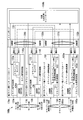
- FIG. 2 is a functional block diagram of the transmission device 100a that performs communication from the line side to the client side according to the first embodiment.
- the transmission device 100a includes a CPU, a memory, an auxiliary storage device, and the like connected by a bus.
- the transmission device 100a represents a configuration for transmitting a signal received from a line side line to a client side line.
- the transmission device 100a includes a line signal receiving unit 140, a line signal receiving unit 140a, a client signal transmitting unit 150, a client signal transmitting unit 150a, and a main board 130a.
- the transmission device 100 and the transmission device 100a are the same device.
- the line signal receiving unit 140 and the line signal transmitting unit 120 may be the same interface card.
- the line signal receiving unit 140a and the line signal transmitting unit 120a may be the same interface card.
- the client signal transmitter 150 and the client signal receiver 110 may be the same interface card.
- the client signal transmitter 150a and the client signal receiver 110a may be the same interface card. In FIG. 2, parts different from the transmission device 100 will be described.
- the line signal receiving unit 140 is connected to the 0-system communication line on the line side.
- the line signal receiver 140 is an interface card.
- the line signal reception unit 140 includes a reception unit 141, an Rx interface 142, an OH extraction unit 143, a client BRG 144, a Chip interface 145, and a Chip interface 146.
- the receiving unit 141 receives the received signal.
- the receiver 141 photoelectrically converts the received signal.
- the reception unit 141 transmits the photoelectrically converted signal to the Rx interface 142.
- the received signal is a redundant OTU4.
- the receiving unit 141 is, for example, an interface such as the QSFP 28, but is not limited to this.
- the Rx interface 142 restores the photoelectrically converted signal to the OTU4 format.
- the Rx interface 142 performs FEC decoding on the restored OTU4.
- the Rx interface 142 transmits the decrypted OTU4 to the OH extraction unit 143.
- the OH extraction unit 143 extracts the OTU4 overhead from the OTU4.
- the OH extractor 143 transmits the in-device frame excluding the FEC overhead of OTU4 to the client BRG 144.
- the client BRG 144 is the beginning of the client redundant section.
- the client redundant section represents a section in which the client BRG 144 to the client signal transmission unit 150 and the client signal transmission unit 150a are made redundant.
- the client BRG 144 transmits the same signal to the working communication line on the client side and the standby communication line on the client side.
- the client BRG 144 duplicates the received in-device frame into the in-device frame 1 and the in-device frame 2.
- the client BRG 144 transmits the duplicated intra-device frame 1 to the Chip interface 145.
- the client BRG 144 transmits the duplicated in-device frame 2 to the Chip interface 146.
- Client BRG 144 is one aspect of the second end.
- the Chip interface 145 converts the received in-device frame 1 into a format that can be transferred between Chips.
- the Chip interface 145 transmits the converted intra-device frame 1 to the connection unit 133a.
- the Chip interface 146 converts the received in-device frame 2 into a format that can be transferred between Chips.
- the Chip interface 146 transmits the converted intra-device frame 2 to the connection unit 133a.
- the line signal receiver 140a is connected to the line 1 side communication line.
- the line signal receiver 140a is an interface card.
- the line signal receiver 140a includes a receiver 141a, an Rx interface 142a, an OH extractor 143a, a client BRG 144a, a Chip interface 145a, and a Chip interface 146a.
- the receiving unit 141a, the Rx interface 142a, and the OH extracting unit 143a perform the same operations as the receiving unit 141, the Rx interface 142, and the OH extracting unit 143, and thus description thereof will be omitted.
- the client BRG 144a is the beginning of the client redundant section.
- the client BRG 144a transmits the same signal to the working communication line on the client side and the backup communication line on the client side.
- the client BRG 144a duplicates the received in-device frame into the in-device frame 3 and the in-device frame 4.
- the client BRG 144a transmits the duplicated in-device frame 3 to the Chip interface 145a.
- the client BRG 144a transmits the duplicated in-device frame 4 to the Chip interface 146a.
- the client BRG 144a is an aspect of the second end portion.
- the Chip interface 145a converts the received in-device frame 3 into a format that can be transferred between Chips.
- the Chip interface 145a transmits the converted in-device frame 3 to the connection unit 134a.
- the Chip interface 146a converts the received in-device frame 4 into a format that can be transferred between Chips.
- the Chip interface 146a transmits the converted in-device frame 4 to the connection unit 134a.
- the client signal transmission unit 150 is connected to the active communication line on the client side.
- the client signal transmitter 150 is an interface card.
- the client signal transmission unit 150 includes a Chip interface 151, a Chip interface 152, a line selector 153, an ODU demapping unit 154, an OH addition unit 155, a Tx interface 156, and a transmission unit 157.
- the client signal transmission unit 150 is an aspect of the second communication device.
- the second communication device communicates with a communication device provided in the second network.
- the Chip interface 151 receives the in-device frame 1 transmitted from the Chip interface 145.
- the Chip interface 151 restores the in-device frame 1 converted to the format that can be transferred between Chips to the format before conversion.
- the Chip interface 151 transmits the restored intra-device frame 1 to the line selector 153.
- the Chip interface 152 receives the in-device frame 3 transmitted from the Chip interface 145a.
- the Chip interface 152 restores the in-device frame 3 converted into the format that can be transferred between Chips to the format before the conversion.
- the Chip interface 152 transmits the restored in-device frame 3 to the line selector 153.
- the line selector 153 is the end of the line redundant section.
- the line redundant section indicates a section in which the line selector 153 to the line signal receiving unit 140 and the line signal receiving unit 140a are made redundant.
- the line selector 153 is input by the user and selects an in-device frame based on a control signal indicating which in-device frame to select.
- the line selector 153 selects either the in-device frame 1 or the in-device frame 3 based on the control signal.
- the user may be any person who monitors the transmission device 100, or any person who can access the transmission device 100a such as a telecommunications carrier.
- the line selector 153 will be described as selecting the in-device frame 1.
- the line selector 153 transmits the selected in-device frame 1 to the OH adding unit 155.
- the line selector 153 is one mode of the first end portion.
- the line selector 153 may select the in-apparatus frame based on the abnormality information instead of the control signal.
- the abnormality information is a signal indicating an abnormality in the network.
- the abnormality information may be, for example, a signal indicating disconnection of the communication line or a signal indicating failure of the transmission device.
- the abnormality information or the control signal may be accepted via a control line connected to the transmission device 100a. Alternatively, the abnormality information or the control signal may be acquired from the OH information extracted by the OH extraction unit 143 or the OH extraction unit 143a.
- the ODU demapping unit 154 demaps 100GE to the in-device frame 1.
- the ODU demapping unit 154 transmits 100GE to the OH addition unit 155.
- the OH addition unit 155 acquires the LACPDU from the redundant controller 135a.
- the OH adding unit 155 adds the acquired LACPDU to 100GE.
- the OH addition unit 155 transmits the 100GE to which the LACPDU is added to the Tx interface 156.
- the Tx interface 156 converts 100GE into a format that can be transferred to the outside of the transmission device 100a.
- the Tx interface 156 transmits the converted 100GE to the transmission unit 157.
- the transmitter 157 converts the input signal into electric light.
- the transmission unit 157 transmits the converted signal to the outside of the transmission device 100a.
- the transmission unit 157 is, for example, an interface such as the QSFP 28, but is not limited to this.
- the transmission unit 157 may use an interface according to the speed of the communication line.
- the client signal transmission unit 150a is connected to the backup communication line on the client side.
- the client signal transmitter 150a is an interface card.
- the client signal transmission unit 150a includes a Chip interface 151a, a Chip interface 152a, a line selector 153a, an ODU demapping unit 154a, an OH addition unit 155a, a Tx interface 156a, and a transmission unit 157a.
- the client signal transmission unit 150a is an aspect of the second communication device.
- the OH addition unit 155a, the Tx interface 156a, and the transmission unit 157a perform the same operations as the OH addition unit 155, the Tx interface 156, and the transmission unit 157, and thus description thereof will be omitted.
- the Chip interface 151a receives the in-device frame 2 transmitted from the Chip interface 146.
- the Chip interface 151a restores the in-device frame 2 converted to the format that can be transferred between Chips to the format before conversion.
- the Chip interface 151a transmits the restored in-device frame 2 to the line selector 153a.
- the Chip interface 152a receives the in-device frame 4 transmitted from the Chip interface 146a.
- the Chip interface 152a restores the in-device frame 4 converted into the format that can be transferred between Chips to the format before the conversion.
- the Chip interface 152a transmits the restored intra-device frame 4 to the line selector 153a.
- the line selector 153a is the end of the line redundant section.
- the line selector 153a selects an in-apparatus frame based on the control signal input by the user.
- the line selector 153a selects either the in-device frame 2 or the in-device frame 4 based on the control signal.
- the line selector 153a selects the in-device frame 2.
- the line selector 153a transmits the selected intra-device frame 2 to the ODU demapping unit 154.
- the line selector 153a is one mode of the first end portion.
- the ODU demapping unit 154a demaps 100GE to the in-device frame 2.
- the ODU demapping unit 154a transmits 100GE to the OH addition unit 155a.
- the main board 130a includes a connecting portion 131a, a connecting portion 132a, a connecting portion 133a, a connecting portion 134a, and a redundant controller 135a.
- the connection unit 131a is a network interface configured such that an interface card can be attached and detached.
- the connection unit 131a communicatively connects the interface card connected to the connection unit 131a and the interface card connected to the connection unit 133a or the connection unit 134a.
- the connection unit 131a connects the client signal transmission unit 150.
- connection unit 132a is a network interface configured such that an interface card can be attached and detached.
- the connection unit 132a connects the interface card connected to the connection unit 132a and the interface card connected to the connection unit 133a or the connection unit 134a in a communicable manner.
- the connection unit 132a connects the client signal transmission unit 150a.
- connection unit 133a is a network interface configured such that an interface card can be attached and detached.
- the connection unit 133a communicatively connects the interface card connected to the connection unit 133a and the interface card connected to the connection unit 131a or the connection unit 132a.
- the connection unit 133a connects the line signal reception unit 140.
- connection unit 134a is a network interface configured such that an interface card can be attached and detached.
- the connection unit 134a connects the interface card connected to the connection unit 134a and the interface card connected to the connection unit 131a or the connection unit 132a in a communicable manner.
- the connection unit 134a connects the line signal reception unit 140a.
- FIG. 3 is a functional block diagram of the transmission device 100b that performs communication from the client side to the line side according to the first embodiment.
- the transmission device 100b includes a CPU, a memory, an auxiliary storage device, and the like connected by a bus.
- the transmission device 100b represents a configuration for transmitting a signal received from a line on the client side to the line on the line side.
- the transmission device 100b includes a main board 130b.
- the main board 130b includes a connecting portion 131b, a connecting portion 132b, a connecting portion 133b, and a connecting portion 134b.
- the connection units 131b to 134b are network interfaces.
- the transmission device 100b can make the interface card pluggable with respect to the main board 130b via the connection units 131b to 134b.
- the interface card can be attached to and detached from the connecting portions 131b to 134b. Note that, in FIG. 3, description of the Tx interface, the ODU mapping unit, and the Chip interface is omitted. In addition, the description of the symbols already described will be omitted.
- the first client-side interface card 160 is connected to the connection unit 131b.
- the connection unit 131b transmits the signal received by the first client-side interface card 160 to the interface cards connected to the connection unit 133b and the connection unit 134b.
- the second client side interface card 160a is connected to the connection unit 132b.
- the connection unit 132b transmits the signal received by the second client-side interface card 160a to the interface card connected to the connection unit 133b and the connection unit 134b.
- the first line side interface card 170 is connected to the connection unit 133b.
- the connection unit 133b transmits the signals transmitted from the interface cards connected to the connection units 131b and 132b to the first line side interface card 170.
- the second line side interface card 170a is connected to the connection portion 134b.
- the connection unit 134b transmits the signals transmitted from the interface cards connected to the connection units 131b and 132b to the second line side interface card 170a.
- the first client-side interface card 160 is an interface card including the client signal receiving unit 110 and the client signal transmitting unit 150.
- the second client side interface card 160a is an interface card including a client signal receiving unit 110a and a client signal transmitting unit 150a.
- the first line side interface card 170 is an interface card including a line signal transmitting unit 120 and a line signal receiving unit 140.
- the second line side interface card 170a is an interface card including a line signal transmitting unit 120a and a line signal receiving unit 140a.
- FIG. 4 is a functional block diagram of the transmission device 100b that performs communication from the line side to the client side according to the first embodiment.
- the transmission device 100b includes a CPU, a memory, an auxiliary storage device, and the like connected by a bus.
- the transmission device 100b in FIG. 4 represents a configuration for transmitting a signal received from a line side line to a client side line. Note that, in FIG. 4, description of the Tx interface, the ODU demapping unit, and the Chip interface is omitted. In addition, the description of the symbols already described will be omitted. In addition, the description of the symbols already described will be omitted.
- connection unit 133b transmits the signal received by the first line-side interface card 170 to the interface cards connected to the connection units 131b and 132b.
- the connection unit 134b transmits the signal received by the second line-side interface card 170a to the interface cards connected to the connection units 131b and 132b.
- the connection unit 131b transmits the signal transmitted from the interface card connected to the connection unit 133b and the connection unit 134b to the first client-side interface card 160.
- connection unit 132b transmits the signal transmitted from the interface card connected to the connection unit 133b and the connection unit 134b to the second client-side interface card 160a.
- the section from the client side interface card to the client BRG is client redundant.
- the section from the line side interface card to the line selector is line redundant. Therefore, the section from the client BRG to the line selector is a section in which the client redundancy and the line redundancy are superimposed.
- the connecting portions of the transmission device configured as shown in FIGS. 1 and 2 are arranged in a straight line from the line side to the client side, in the transmission device 100b configured as shown in FIGS. 3 and 4.
- the interface card can be made pluggable with respect to the main board 130b via the connection portions 131b to 134b. With such a configuration, the transmission device 100b can suppress deterioration in reliability of the main board 130b and the connection parts 131b to 134b. Further, the transmission device 100b can be easily replaced even in the event of a failure by using two types of interface cards, a line side interface card and a client side interface card.
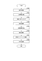
- FIG. 5 is a flowchart showing the flow of processing in which the transmission device 100 of the first embodiment transmits from the client side line to the line side line. This process is executed when a signal is received from the client side line. Note that, although FIG. 5 illustrates the processing in the client signal receiving unit 110 connected to the active communication line on the client side, the same applies to the client signal receiving unit 110a connected to the communication line of the standby system on the client side. Is processed.
- the receiving unit 111 of the transmission device 100 receives the received signal (step S101).
- the client redundant OH extraction unit 113 acquires a LACPDU from the received signal (step S102).
- the client redundant OH extraction unit 113 transmits the acquired LACPDU to the redundant controller 135.
- the ODU mapping unit 114 maps the received signal to ODU4 (step S103).
- the line BRG 115 copies ODU4 to ODU4-1 and ODU4-2 (step S104).
- the line BRG 115 transmits ODU4-1 and ODU4-2 to the line signal transmission unit 120 and the line signal transmission unit 120a via the redundant section (step S105).
- the redundant section is a section connected by the line BRG 115 and the client selector 123.
- the redundant section is a section in which the redundant configuration of the client signal receiving unit 110 and the redundant configuration of the line signal transmitting unit 120 overlap each other.
- the client selector 123 selects either one of the ODU4 received from the client signal receiving unit 110 or the client signal receiving unit 110a based on the control determined by the redundant controller 135 (step S106).
- the OH adding unit 124 inserts the OTU4 overhead into the selected ODU4 (step S107).
- the transmission unit 126 transmits OTU4 to the outside of the transmission device 100 (step S108).
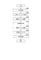
- FIG. 6 is a flowchart showing the flow of processing in which the transmission device 100a of the first embodiment transmits from the line side line to the client side line. This processing is executed when OTU4 is received from the line side line. Note that FIG. 6 describes the processing in the line signal receiving unit 140 connected to the line 0 system line, but the same processing is performed in the line signal receiving unit 140a connected to the line side 1 system line. Be seen.
- the receiving unit 141 of the transmission device 100 receives the OTU4 (step S201).
- the OH extraction unit 143 extracts the OTU overhead from the OTU 4 (step S202).
- the client BRG 144 duplicates the in-device frame into the in-device frame 1 and the in-device frame 2 (step S203).
- the client BRG 144 transmits the in-device frame 1 and the in-device frame 2 to the client signal transmission unit 150 and the client signal transmission unit 150a via the redundant section (step S204).
- the redundant section is a transmission section between the client BRG 144 and the line selector 153.
- the redundant section is a section connected by the client BRG 144 and the line selector 153.
- the redundant section is a section in which the redundant configuration of the client signal transmitting unit 150 and the redundant configuration of the line signal receiving unit 140 overlap each other.
- the line selector 153 selects either the in-device frame received from the line signal receiving unit 140 or the line signal receiving unit 140a based on the control signal from the operator or the abnormality information (step S205).
- the ODU demapping unit 154 demaps 100GE to the selected intra-device frame (step S206).
- the transmission unit 157 transmits the converted 100GE to the outside of the transmission device 100a (step S207).
- the client selector 123 provided in the line signal transmitting unit 120 and the client selector 123a provided in the line signal transmitting unit 120a are the client signal receiving unit 110 and the client signal receiving unit 110a. Terminate the redundant configuration of. Further, the line BRG 115 provided in the client signal receiving section 110 and the line BRG 115a provided in the client signal receiving section 110a start the redundant configuration of the line signal transmitting section 120 and the line signal transmitting section 120a. Therefore, between the line BRG 115 and the client selector 123, the client redundant section and the line redundant section are overlapped and quadrupled.
- the transmission device 100 can improve the reliability of communication between the interface card connection unit such as the line signal reception unit and the interface card connection unit such as the client signal transmission unit.
- the line selector 153 provided in the client signal transmitting unit 150 and the line selector 153a provided in the client signal transmitting unit 150a are the line signal receiving unit 140 and the line signal receiving unit 140a. Terminate the redundant configuration of. Also, the client BRG 144 provided in the line signal receiving unit 140 and the client BRG 144a provided in the line signal receiving unit 140a start the redundant configuration of the client signal transmitting unit 150 and the client signal transmitting unit 150a. Therefore, between the client BRG 144 and the line selector 153, the client redundant section and the line redundant section are overlapped and quadrupled.
- the transmission device 100a can improve the reliability of communication between the interface card connection unit such as the line signal transmission unit and the interface card connection unit such as the client signal reception unit.
- the transmission device 100 or the transmission device 100a configured as described above, since the communication between the line side interface card and the client side interface card is made redundant, the line side interface card and the client side interface card are connected. There is no need to build a separate facility to secure the trust between them. Therefore, the reliability can be improved with a smaller device configuration. Further, since the reliability can be improved with a smaller device configuration, by using the transmission device, it becomes possible to construct a network at a lower cost and improve the reliability.
- FIG. 7 is a functional block diagram of the transmission device 100c according to the second embodiment.
- the transmission device 100c includes a CPU, a memory, an auxiliary storage device, and the like connected by a bus.
- the transmission device 100c represents a configuration for transmitting a signal received from a line on the client side to the line on the line side.
- the transmission device 100c includes a main board 130c.
- the transmission device 100c is configured to include the client signal reception unit 110, the client signal reception unit 110a, the client signal transmission unit 150, and the client signal transmission unit 150a according to the first embodiment on the main board 130c. Note that, in FIG. 7, description of the Tx interface, the ODU mapping unit, and the Chip interface is omitted. In addition, the description of the symbols already described will be omitted.
- the main board 130c includes a connecting unit 133c, a connecting unit 134c, a redundant controller 135, a client signal receiving unit 110, a client signal receiving unit 110a, a client signal transmitting unit 150, and a client signal transmitting unit 150a.
- the connection unit 133c and the connection unit 134c are network interfaces.
- the interface 133c and the connector 134c are configured such that the interface card can be attached and detached.
- the connection unit 133c is connected to the first line side interface card 170.
- the second line side interface card 170a is connected to the connecting portion 134c.
- the transmission device 100c configured as described above includes a client signal transmission unit 150 and a client signal transmission unit 150a on the main board 130c. Therefore, the line-side interface card can be pluggable. Therefore, in the transmission device 100c, the type of interface card can be one type of the line side interface card, and even if the line side interface card fails, it can be easily replaced. A person who maintains or inspects the transmission device 100c can easily maintain the transmission device 100c.
- APS Automatic Protection Switching
- the overhead of client redundancy may be used.
- the transmission device may be a transmission device in which N client-side interface cards and M line-side interface cards can be attached and detached.
- N is a natural number of 2 or more.
- M is a natural number of 2 or more.
- the transmission device may be implemented using a plurality of information processing devices that are communicably connected via a network.
- the functional units included in the transmission device may be distributed and implemented in a plurality of information processing devices.
- the redundant controller 135 may be implemented in a different information processing device.
- the transmission device in the above-described embodiment may be realized by a computer.
- the program for realizing this function may be recorded in a computer-readable recording medium, and the program recorded in this recording medium may be read by a computer system and executed.
- the “computer system” mentioned here includes an OS and hardware such as peripheral devices.
- the “computer-readable recording medium” refers to a portable medium such as a flexible disk, a magneto-optical disk, a ROM, a CD-ROM, or a storage device such as a hard disk built in a computer system.
- the "computer-readable recording medium” means to hold a program dynamically for a short time like a communication line when transmitting the program through a network such as the Internet or a communication line such as a telephone line.
- a volatile memory inside a computer system that serves as a server or a client in that case may hold a program for a certain period of time.
- the program may be for realizing some of the functions described above, or may be one that can realize the functions described above in combination with a program already recorded in the computer system, It may be realized using a programmable logic device such as FPGA (Field Programmable Gate Array).
- Chip interface 146...Chip interface, 150...Client signal transmitting unit, 151...Chip interface, 152...Chip interface, 153... Line selector, 154... ODU demapping section, 155... OH addition section, 156...Tx interface, 157...Transmission unit
Landscapes
- Engineering & Computer Science (AREA)
- Computer Networks & Wireless Communication (AREA)
- Signal Processing (AREA)
- Data Exchanges In Wide-Area Networks (AREA)
- Communication Control (AREA)
Abstract
第1のネットワークに設けられた通信装置と通信を行い、冗長化された第1通信機器と第2のネットワークに設けられた通信装置と通信を行い、冗長化された第2通信機器とを備え、前記第2通信機器は、前記第1通信機器の冗長化された通信路の末端である第1端部をそれぞれ備え、前記第1通信機器は、前記第2通信機器の冗長化された通信路の末端である第2端部をそれぞれ備える、伝送装置である。
Description
本発明は、伝送装置及び伝送方法に関する。
伝送装置は、LAG冗長又はSDH冗長等のようにクライアント側回線の冗長化(クライアント冗長)と、無瞬断切替が行われるライン側回線の冗長化(ライン冗長)とが併用された装置であることが必要である。従来の伝送装置は、クライアント冗長の終端処理を行い、クライアント信号をODU(Optical Channel Data Unit)にマッピングした後に、ライン冗長を行う。しかし、図8に示されるように、伝送装置内のクライアント冗長の区間とライン冗長の区間との間は冗長化されていない。このため、伝送装置は二回線-単一経路-二回線で構成されている。
しかしながら、単一経路の区間にインタフェースカードとメインボードとの接続部分を伝送装置が備える場合は、接続部分における信頼性が低下する問題があった。
上記事情に鑑み、本発明は、伝送装置の信頼性をより高めることができる技術を提供することを目的としている。
本発明の一態様は、第1のネットワークに設けられた通信装置と通信を行い、冗長化された第1通信機器と第2のネットワークに設けられた通信装置と通信を行い、冗長化された第2通信機器とを備え、前記第2通信機器は、前記第1通信機器の冗長化された通信路の末端である第1端部をそれぞれ備え、前記第1通信機器は、前記第2通信機器の冗長化された通信路の末端である第2端部をそれぞれ備える、伝送装置である。
本発明の一態様は、上記の伝送装置であって、前記第1端部は、前記第2通信機器によって受信された受信信号を前記第1通信機器に向けて送信し、前記第2端部は、前記第2通信機器から送信された受信信号のうちいずれか1つをそれぞれ選択する。
本発明の一態様は、上記の伝送装置であって、前記第2通信機器の冗長の状態を表す冗長情報を前記第2通信機器から取得し、前記冗長情報に基づいて、前記第2端部によって選択される受信信号を制御する冗長コントローラをさらに備える。
本発明の一態様は、上記の伝送装置であって、前記第2端部は、前記第1通信機器によって受信された受信信号を前記第2通信機器に向けて送信し、前記第1端部は、前記第1通信機器から送信された受信信号のうちいずれか1つをそれぞれ選択する。
本発明の一態様は、上記の伝送装置であって、前記第1端部は、ネットワークの異常を示す異常情報又はユーザによって入力され、いずれの受信信号を選択するかを制御する制御信号に基づいて、前記受信信号のうちいずれか1つをそれぞれ選択する。
本発明の一態様は、上記の伝送装置であって、前記第1通信機器又は前記第2通信機器のうち、1つ以上はインタフェースカードである。
本発明の一態様は、伝送装置が、冗長化された第2通信機器によって受信された信号を、冗長化された第1通信機器の通信路の末端である第1端部において複製して、前記第1通信機器に伝送する伝送ステップと、伝送装置が、前記第2通信機器の冗長化された通信路の末端である第2端部において、前記第2通信機器から送信された信号のうちいずれか1つをそれぞれ選択する選択ステップと、伝送装置が、前記選択された信号を第1のネットワークに送信する、伝送方法である。
本発明により、伝送装置の信頼性をより高めることが可能となる。
(第1の実施形態)
図1は、第1の実施形態のクライアント側からライン側への通信を行う伝送装置100の機能ブロック図である。伝送装置100は、バスで接続されたCPU(Central Processing Unit)やメモリや補助記憶装置などを備える。伝送装置100は、クライアント側の回線から受信した信号をライン側の回線に送信する場合の構成を表す。伝送装置100は、クライアント信号受信部110、クライアント信号受信部110a、ライン信号送信部120、ライン信号送信部120a及びメインボード130を備える。
図1は、第1の実施形態のクライアント側からライン側への通信を行う伝送装置100の機能ブロック図である。伝送装置100は、バスで接続されたCPU(Central Processing Unit)やメモリや補助記憶装置などを備える。伝送装置100は、クライアント側の回線から受信した信号をライン側の回線に送信する場合の構成を表す。伝送装置100は、クライアント信号受信部110、クライアント信号受信部110a、ライン信号送信部120、ライン信号送信部120a及びメインボード130を備える。
クライアント信号受信部110は、クライアント側の現用系の通信回線に接続される。
クライアント信号受信部110は、インタフェースカードである。クライアント信号受信部110は、受信部111、Rxインタフェース112、クライアント冗長OH(Over Head)抽出部113、ODUマッピング部114、ラインBRG115、Chipインタフェース116及びChipインタフェース117を備える。クライアント側の現用系の通信回線は、例えば100Gの通信速度であってもよいが、100Gに限定されない。クライアント信号受信部110は、第2通信機器の一態様である。
クライアント信号受信部110は、インタフェースカードである。クライアント信号受信部110は、受信部111、Rxインタフェース112、クライアント冗長OH(Over Head)抽出部113、ODUマッピング部114、ラインBRG115、Chipインタフェース116及びChipインタフェース117を備える。クライアント側の現用系の通信回線は、例えば100Gの通信速度であってもよいが、100Gに限定されない。クライアント信号受信部110は、第2通信機器の一態様である。
受信部111は、受信信号を受信する。受信部111は、受信信号を光電気変換する。
受信部111は、光電気変換された受信信号をRxインタフェース112に送信する。受信信号は、L2スイッチ等で冗長化された100GE(Gigabit Ethernet)の信号である。受信部111は、例えば、QSFP28等のインタフェースであるが、これに限定されない。受信部111は、通信回線の速度又は種類に応じたどのようなインタフェースが用いられてもよい。
受信部111は、光電気変換された受信信号をRxインタフェース112に送信する。受信信号は、L2スイッチ等で冗長化された100GE(Gigabit Ethernet)の信号である。受信部111は、例えば、QSFP28等のインタフェースであるが、これに限定されない。受信部111は、通信回線の速度又は種類に応じたどのようなインタフェースが用いられてもよい。
Rxインタフェース112は、光電気変換された受信信号を100GEのフォーマットに復元する。Rxインタフェース112は、復元された受信信号をクライアント冗長OH抽出部113に送信する。
クライアント冗長OH抽出部113は、受信信号からLACPDU(Link Aggregation Control Protocol Data Unit)を抽出する。クライアント冗長OH抽出部113は、抽出されたLACPDUを冗長コントローラ135に送信する。クライアント冗長OH抽出部113は、LACPDUが抽出された後の受信信号をODUマッピング部114へ送信する。LACPDUは、冗長情報の一態様である。冗長情報は、複数のクライアント信号受信部の冗長の状態を表す。冗長の状態とは、例えば、どのクライアント信号受信部が冗長化されているか等を表す情報である。
ODUマッピング部114は、受信された受信信号をODU4にマッピングする。ODUマッピング部114は、マッピングされたODU4にODUオーバーヘッドを付加する。ODUマッピング部114は、ODUオーバーヘッドが付加されたODU4を、ラインBRG115に送信する。
ラインBRG115は、ライン冗長区間の始端である。ライン冗長区間は、ライン信号送信部120及びライン信号送信部120aの冗長化された構成を表す区間である。ラインBRG115は、無瞬断切り替えのために、受信されたODU4をライン側の0系回線とライン側の1系回線とに送信する。具体的には、ラインBRG115は、ODU4をODU4-1及びODU4-2に複製する。ラインBRG115は、複製されたODU4-1をChipインタフェース116に送信する。ラインBRG115は、複製されたODU4-2をChipインタフェース117に送信する。ラインBRG115は、第1端部の一態様である。
Chipインタフェース116は、受信したODU4-1を、Chip間転送可能なフォーマットに変換する。Chipインタフェース116は、変換されたODU4-1を接続部131に送信する。Chipインタフェース117は、受信したODU4-2を、Chip間転送可能なフォーマットに変換する。Chipインタフェース117は、変換されたODU4-2を接続部131に送信する。
クライアント信号受信部110aは、クライアント側の予備系の通信回線に接続される。クライアント信号受信部110aは、インタフェースカードである。クライアント信号受信部110aは、受信部111a、Rxインタフェース112a、クライアント冗長OH抽出部113a、ODUマッピング部114a、ラインBRG115a、Chipインタフェース116a及びChipインタフェース117aを備える。クライアント側の予備系の通信回線は、例えば100Gの通信速度であってもよいが、100Gに限定されない。クライアント信号受信部110aは、第2通信機器の一態様である。クライアント側の予備系の通信回線はLACP等のプロトコルによって、現用系の通信回線と冗長化される。なお、受信部111a、Rxインタフェース112a、クライアント冗長OH抽出部113a及びODUマッピング部114aは、受信部111、Rxインタフェース112、クライアント冗長OH抽出部113及びODUマッピング部114と同様の動作を行うため、説明を省略する。
ラインBRG115aは、ライン冗長区間の始端である。ライン冗長区間は、ライン信号送信部120及びライン信号送信部120aの冗長化された構成を表す区間である。ラインBRG115aは、無瞬断切り替えのために、受信されたODU4をライン側の0系回線とライン側の1系回線とに送信する。具体的には、ラインBRG115aは、ODU4をODU4-3及びODU4-4に複製する。ラインBRG115aは、複製されたODU4-3をChipインタフェース116aに送信する。ラインBRG115aは、複製されたODU4-4をChipインタフェース117aに送信する。ラインBRG115aは、第1端部の一態様である。
Chipインタフェース116aは、受信したODU4-3を、Chip間転送可能なフォーマットに変換する。Chipインタフェース116aは、変換されたODU4-3を接続部132に送信する。Chipインタフェース117aは、受信したODU4-4を、Chip間転送可能なフォーマットに変換する。Chipインタフェース117aは、変換されたODU4-4を接続部132に送信する。
ライン信号送信部120は、ライン側の0系の通信回線に接続される。ライン信号送信部120は、インタフェースカードである。ライン信号送信部120は、Chipインタフェース121、Chipインタフェース122、クライアントセレクタ123、OH付加部124、Txインタフェース125及び送信部126を備える。ライン信号送信部120は、第1通信機器の一態様である。第1通信機器は、第1のネットワークに設けられた通信装置と通信を行う。
Chipインタフェース121は、Chipインタフェース116から送信されたODU4-1を受信する。Chipインタフェース121は、Chip間転送可能なフォーマットに変換されたODU4-1を、変換前のフォーマットに復元する。Chipインタフェース121は、復元されたODU4-1をクライアントセレクタ123に送信する。Chipインタフェース122は、Chipインタフェース116aから送信されたODU4-3を受信する。Chipインタフェース122は、Chip間転送可能なフォーマットに変換されたODU4-3を、変換前のフォーマットに復元する。Chipインタフェース122は、復元されたODU4-3をクライアントセレクタ123に送信する。
クライアントセレクタ123は、クライアント冗長区間の終端である。クライアント冗長区間は、クライアント信号受信部110及びクライアント信号受信部110aの冗長化された構成を表す区間である。クライアントセレクタ123は、冗長コントローラ135によって決定された制御に基づいて、ODU4-1又はODU4-3のうちいずれか一方を選択する。以下、クライアントセレクタ123は、ODU4-1を選択するものとして説明する。クライアントセレクタ123は、選択されたODU4-1をOH付加部124に送信する。クライアントセレクタ123は、第2端部の一態様である。
OH付加部124は、選択されたODU4-1にOTU4オーバーヘッドを挿入する。
OH付加部124は、OTU4オーバーヘッドを付加されたOTU4-1をTxインタフェース125に送信する。
OH付加部124は、OTU4オーバーヘッドを付加されたOTU4-1をTxインタフェース125に送信する。
Txインタフェース125は、OTU4-1に対して、FEC(Forward Error Correction)符号化を行う。Txインタフェース125は、FEC符号化されたOTU4-1をOTL(Optical Channel Transport Lane)4.4のインタフェースに変換する。OTL4.4は、4つの物理レーンに分けられたOTU4である。Txインタフェース125は、変換されたOTU4-1を送信部126に送信する。
送信部126は、入力された信号(OTU4-1)を電気光変換する。送信部126は、変換されたOTU4-1を伝送装置100の外部へ送信する。送信部126は、例えば、QSFP28等のインタフェースであるが、これに限定されない。送信部126は、通信回線の速度に応じたインタフェースが用いられてもよい。
ライン信号送信部120aは、ライン側の1系の通信回線に接続される。ライン信号送信部120aは、インタフェースカードである。ライン信号送信部120aは、Chipインタフェース121a、Chipインタフェース122a、クライアントセレクタ123a、OH付加部124a、Txインタフェース125a及び送信部126aを備える。
ライン信号送信部120aは、第1通信機器の一態様である。ライン側0系の通信回線とライン側の1系の通信回線とは無瞬断切替によって冗長化される。なお、OH付加部124a、Txインタフェース125a及び送信部126aは、OH付加部124、Txインタフェース125及び送信部126と同様の動作を行うため、説明を省略する。
ライン信号送信部120aは、第1通信機器の一態様である。ライン側0系の通信回線とライン側の1系の通信回線とは無瞬断切替によって冗長化される。なお、OH付加部124a、Txインタフェース125a及び送信部126aは、OH付加部124、Txインタフェース125及び送信部126と同様の動作を行うため、説明を省略する。
Chipインタフェース121aは、Chipインタフェース117から送信されたODU4-2を受信する。Chipインタフェース121aは、Chip間転送可能なフォーマットに変換されたODU4-2を、変換前のフォーマットに復元する。Chipインタフェース121aは、復元されたODU4-2をクライアントセレクタ123aに送信する。Chipインタフェース122aは、Chipインタフェース117aから送信されたODU4-4を受信する。Chipインタフェース122aは、Chip間転送可能なフォーマットに変換されたODU4-4を、変換前のフォーマットに復元する。Chipインタフェース122aは、復元されたODU4-4をクライアントセレクタ123aに送信する。
クライアントセレクタ123aは、クライアント冗長区間の終端である。クライアントセレクタ123aは、冗長コントローラ135によって決定された制御に基づいて、ODU4-2又はODU4-4のうちいずれか一方を選択する。以下、クライアントセレクタ123aは、ODU4-2を選択するものとして説明する。クライアントセレクタ123aは、選択されたODU4-2をOH付加部124aに送信する。クライアントセレクタ123aは、第2端部の一態様である。
メインボード130は、接続部131、接続部132、接続部133、接続部134及び冗長コントローラ135を備える。接続部131は、インタフェースカードを着脱可能に構成されたネットワークインタフェースである。接続部131は、接続部131に接続されたインタフェースカードと接続部133又は接続部134に接続されたインタフェースカードとを通信可能に接続する。接続部131は、クライアント信号受信部110を接続する。
接続部132は、インタフェースカードを着脱可能に構成されたネットワークインタフェースである。接続部132は、接続部132に接続されたインタフェースカードと接続部133又は接続部134に接続されたインタフェースカードとを通信可能に接続する。
接続部132は、クライアント信号受信部110aを接続する。
接続部132は、クライアント信号受信部110aを接続する。
接続部133は、インタフェースカードを着脱可能に構成されたネットワークインタフェースである。接続部133は、接続部133に接続されたインタフェースカードと接続部131又は接続部132に接続されたインタフェースカードとを通信可能に接続する。
接続部133は、ライン信号送信部120を接続する。
接続部133は、ライン信号送信部120を接続する。
接続部134は、インタフェースカードを着脱可能に構成されたネットワークインタフェースである。接続部134は、接続部134に接続されたインタフェースカードと接続部131又は接続部132に接続されたインタフェースカードとを通信可能に接続する。
接続部134は、ライン信号送信部120aを接続する。
接続部134は、ライン信号送信部120aを接続する。
冗長コントローラ135は、LACPDUに基づいて、クライアントセレクタ123によって選択されるODU4を決定する。第1の実施形態において、冗長コントローラ135は、クライアント冗長OH抽出部113によって送信されたLACPDUに基づいて、クライアントセレクタ123によってODU4-1又はODU4-3のうち、いずれが選択されるかを決定する。冗長コントローラ135は、決定結果をクライアントセレクタ123に送信する。第1の実施形態において、冗長コントローラ135は、クライアント冗長OH抽出部113aによって送信されたLACPDUに基づいて、クライアントセレクタ123aによってODU4-2又はODU4-4のうち、いずれが選択されるかを決定する。冗長コントローラ135は、決定結果をクライアントセレクタ123aに送信する。
図1の伝送装置100では、クライアント信号受信部110の受信部111及びクライアント信号受信部110aの受信部111aから、クライアントセレクタ123及びクライアントセレクタ123aまでの区間が、クライアント冗長(LAG冗長)の区間である。また、ラインBRG115及びラインBRG115aから、ライン信号送信部120の送信部126及びライン信号送信部120aの送信部126aまでの区間が、ライン冗長(無瞬断切替)の区間である。したがって、伝送装置100において、ラインBRG115及びラインBRG115aからクライアントセレクタ123及びクライアントセレクタ123aまでの区間は、クライアント冗長の区間とライン冗長の区間とが二重に重ね合わせて構成される。したがって、上述の区間は4経路の冗長性が確保される。
図2は、第1の実施形態のライン側からクライアント側への通信を行う伝送装置100aの機能ブロック図である。伝送装置100aは、バスで接続されたCPUやメモリや補助記憶装置などを備える。伝送装置100aは、ライン側の回線から受信した信号をクライアント側の回線に送信する場合の構成を表す。伝送装置100aは、ライン信号受信部140、ライン信号受信部140a、クライアント信号送信部150、クライアント信号送信部150a及びメインボード130aを備える。なお、伝送装置100と伝送装置100aとは、同一の装置である。ライン信号受信部140とライン信号送信部120とは、同一のインタフェースカードであってもよい。ライン信号受信部140aとライン信号送信部120aとは、同一のインタフェースカードであってもよい。クライアント信号送信部150とクライアント信号受信部110とは、同一のインタフェースカードであってもよい。クライアント信号送信部150aとクライアント信号受信部110aとは、同一のインタフェースカードであってもよい。図2では、伝送装置100と異なる部分について説明する。
ライン信号受信部140は、ライン側の0系の通信回線に接続される。ライン信号受信部140は、インタフェースカードである。ライン信号受信部140は、受信部141、Rxインタフェース142、OH抽出部143、クライアントBRG144、Chipインタフェース145及びChipインタフェース146を備える。
受信部141は、受信信号を受信する。受信部141は、受信信号を光電気変換する。
受信部141は、光電気変換された信号をRxインタフェース142に送信する。受信信号は、冗長化されたOTU4である。受信部141は、例えば、QSFP28等のインタフェースであるが、これに限定されない。
受信部141は、光電気変換された信号をRxインタフェース142に送信する。受信信号は、冗長化されたOTU4である。受信部141は、例えば、QSFP28等のインタフェースであるが、これに限定されない。
Rxインタフェース142は、光電気変換された信号をOTU4のフォーマットに復元する。Rxインタフェース142は、復元されたOTU4に対してFEC復号化を行う。
Rxインタフェース142は、復号されたOTU4をOH抽出部143に送信する。
Rxインタフェース142は、復号されたOTU4をOH抽出部143に送信する。
OH抽出部143は、OTU4からOTU4オーバーヘッドを抽出する。OH抽出部143は、OTU4のFECオーバーヘッドを除いた装置内フレームをクライアントBRG144に送信する。
クライアントBRG144は、クライアント冗長区間の始端である。図2において、クライアント冗長区間は、クライアントBRG144からクライアント信号送信部150及びクライアント信号送信部150aまでの冗長化された区間を表す。クライアントBRG144は、クライアント側の現用系の通信回線とクライアント側の予備系の通信回線とに対して、同じ信号を送信する。クライアントBRG144は、受信されたO装置内フレームを装置内フレーム1及び装置内フレーム2に複製する。クライアントBRG144は、複製された装置内フレーム1をChipインタフェース145に送信する。クライアントBRG144は、複製された装置内フレーム2をChipインタフェース146に送信する。クライアントBRG144は、第2端部の一態様である。
Chipインタフェース145は、受信した装置内フレーム1を、Chip間転送可能なフォーマットに変換する。Chipインタフェース145は、変換された装置内フレーム1を接続部133aに送信する。Chipインタフェース146は、受信した装置内フレーム2を、Chip間転送可能なフォーマットに変換する。Chipインタフェース146は、変換された装置内フレーム2を接続部133aに送信する。
ライン信号受信部140aは、ライン側の1系の通信回線に接続される。ライン信号受信部140aは、インタフェースカードである。ライン信号受信部140aは、受信部141a、Rxインタフェース142a、OH抽出部143a、クライアントBRG144a、Chipインタフェース145a及びChipインタフェース146aを備える。なお、受信部141a、Rxインタフェース142a及びOH抽出部143aは、受信部141、Rxインタフェース142及びOH抽出部143と同様の動作を行うため、説明を省略する。
クライアントBRG144aは、クライアント冗長区間の始端である。クライアントBRG144aは、クライアント側の現用系の通信回線とクライアント側の予備系の通信回線とに対して、同じ信号を送信する。クライアントBRG144aは、受信された装置内フレームを装置内フレーム3及び装置内フレーム4に複製する。クライアントBRG144aは、複製された装置内フレーム3をChipインタフェース145aに送信する。クライアントBRG144aは、複製された装置内フレーム4をChipインタフェース146aに送信する。クライアントBRG144aは、第2端部の一態様である。
Chipインタフェース145aは、受信した装置内フレーム3を、Chip間転送可能なフォーマットに変換する。Chipインタフェース145aは、変換された装置内フレーム3を接続部134aに送信する。Chipインタフェース146aは、受信した装置内フレーム4を、Chip間転送可能なフォーマットに変換する。Chipインタフェース146aは、変換された装置内フレーム4を接続部134aに送信する。
クライアント信号送信部150は、クライアント側の現用系の通信回線に接続される。
クライアント信号送信部150は、インタフェースカードである。クライアント信号送信部150は、Chipインタフェース151、Chipインタフェース152、ラインセレクタ153、ODUデマッピング部154、OH付加部155、Txインタフェース156及び送信部157を備える。クライアント信号送信部150は、第2通信機器の一態様である。第2通信機器は、第2のネットワークに設けられた通信装置と通信を行う。
クライアント信号送信部150は、インタフェースカードである。クライアント信号送信部150は、Chipインタフェース151、Chipインタフェース152、ラインセレクタ153、ODUデマッピング部154、OH付加部155、Txインタフェース156及び送信部157を備える。クライアント信号送信部150は、第2通信機器の一態様である。第2通信機器は、第2のネットワークに設けられた通信装置と通信を行う。
Chipインタフェース151は、Chipインタフェース145から送信された装置内フレーム1を受信する。Chipインタフェース151は、Chip間転送可能なフォーマットに変換された装置内フレーム1を、変換前のフォーマットに復元する。Chipインタフェース151は、復元された装置内フレーム1をラインセレクタ153に送信する。Chipインタフェース152は、Chipインタフェース145aから送信された装置内フレーム3を受信する。Chipインタフェース152は、Chip間転送可能なフォーマットに変換された装置内フレーム3を、変換前のフォーマットに復元する。Chipインタフェース152は、復元された装置内フレーム3をラインセレクタ153に送信する。
ラインセレクタ153は、ライン冗長区間の終端である。図2において、ライン冗長区間は、ラインセレクタ153からライン信号受信部140及びライン信号受信部140aまでの冗長化された区間を表す。ラインセレクタ153はユーザによって入力され、いずれの装置内フレームを選択するかを制御信号に基づいて、装置内フレームを選択する。ラインセレクタ153は、制御信号に基づいて、装置内フレーム1又は装置内フレーム3のうちいずれか一方を選択する。ユーザは、伝送装置100を監視する者や、電気通信事業者等の伝送装置100aにアクセスできるものであればどのような者であってもよい。以下、ラインセレクタ153は、装置内フレーム1を選択するものとして説明する。ラインセレクタ153は、選択された装置内フレーム1をOH付加部155に送信する。ラインセレクタ153は、第1端部の一態様である。なお、ラインセレクタ153は、制御信号の代わりに異常情報に基づいて、装置内フレームを選択してもよい。異常情報は、ネットワークの異常を示す信号である。異常情報は、例えば、通信回線の切断を示す信号であってもよいし、伝送装置の故障を示す信号であってもよい。異常情報又は制御信号は、伝送装置100aに接続された制御用の回線を介して受け付けてもよい。または、異常情報又は制御信号は、OH抽出部143又はOH抽出部143aによって抽出されたOH情報から取得してもよい。
ODUデマッピング部154は、装置内フレーム1に対して100GEをデマッピングする。ODUデマッピング部154は、100GEをOH付加部155に送信する。
OH付加部155は、冗長コントローラ135aからLACPDUを取得する。OH付加部155は、取得されたLACPDUを100GEに付加する。OH付加部155は、LACPDUを付加された100GEをTxインタフェース156に送信する。
Txインタフェース156は、100GEを伝送装置100aの外部に転送可能なフォーマットに変換する。Txインタフェース156は、変換された100GEを送信部157に送信する。
送信部157は、入力された信号を電気光変換する。送信部157は、変換された信号を伝送装置100aの外部へ送信する。送信部157は、例えば、QSFP28等のインタフェースであるが、これに限定されない。送信部157は、通信回線の速度に応じたインタフェースが用いられてもよい。
クライアント信号送信部150aは、クライアント側の予備系の通信回線に接続される。クライアント信号送信部150aは、インタフェースカードである。クライアント信号送信部150aは、Chipインタフェース151a、Chipインタフェース152a、ラインセレクタ153a、ODUデマッピング部154a、OH付加部155a、Txインタフェース156a及び送信部157aを備える。クライアント信号送信部150aは、第2通信機器の一態様である。なお、OH付加部155a、Txインタフェース156a及び送信部157aは、OH付加部155、Txインタフェース156及び送信部157と同様の動作を行うため、説明を省略する。
Chipインタフェース151aは、Chipインタフェース146から送信された装置内フレーム2を受信する。Chipインタフェース151aは、Chip間転送可能なフォーマットに変換された装置内フレーム2を、変換前のフォーマットに復元する。Chipインタフェース151aは、復元された装置内フレーム2をラインセレクタ153aに送信する。Chipインタフェース152aは、Chipインタフェース146aから送信された装置内フレーム4を受信する。Chipインタフェース152aは、Chip間転送可能なフォーマットに変換された装置内フレーム4を、変換前のフォーマットに復元する。Chipインタフェース152aは、復元された装置内フレーム4をラインセレクタ153aに送信する。
ラインセレクタ153aは、ライン冗長区間の終端である。ラインセレクタ153aは、ユーザから入力された制御信号に基づいて、装置内フレームを選択する。ラインセレクタ153aは、制御信号に基づいて、装置内フレーム2又は装置内フレーム4のうちいずれか一方を選択する。以下、ラインセレクタ153aは、装置内フレーム2を選択するものとして説明する。ラインセレクタ153aは、選択された装置内フレーム2をODUデマッピング部154に送信する。ラインセレクタ153aは、第1端部の一態様である。
ODUデマッピング部154aは、装置内フレーム2に対して100GEをデマッピングする。ODUデマッピング部154aは、100GEをOH付加部155aに送信する。
メインボード130aは、接続部131a、接続部132a、接続部133a、接続部134a及び冗長コントローラ135aを備える。接続部131aは、インタフェースカードを着脱可能に構成されたネットワークインタフェースである。接続部131aは、接続部131aに接続されたインタフェースカードと接続部133a又は接続部134aに接続されたインタフェースカードとを通信可能に接続する。接続部131aは、クライアント信号送信部150を接続する。
接続部132aは、インタフェースカードを着脱可能に構成されたネットワークインタフェースである。接続部132aは、接続部132aに接続されたインタフェースカードと接続部133a又は接続部134aに接続されたインタフェースカードとを通信可能に接続する。接続部132aは、クライアント信号送信部150aを接続する。
接続部133aは、インタフェースカードを着脱可能に構成されたネットワークインタフェースである。接続部133aは、接続部133aに接続されたインタフェースカードと接続部131a又は接続部132aに接続されたインタフェースカードとを通信可能に接続する。接続部133aは、ライン信号受信部140を接続する。
接続部134aは、インタフェースカードを着脱可能に構成されたネットワークインタフェースである。接続部134aは、接続部134aに接続されたインタフェースカードと接続部131a又は接続部132aに接続されたインタフェースカードとを通信可能に接続する。接続部134aは、ライン信号受信部140aを接続する。
図3は、第1の実施形態のクライアント側からライン側への通信を行う伝送装置100bの機能ブロック図である。伝送装置100bは、バスで接続されたCPUやメモリや補助記憶装置などを備える。伝送装置100bは、クライアント側の回線から受信した信号をライン側の回線に送信する場合の構成を表す。伝送装置100bは、メインボード130bを備える。メインボード130bは、接続部131b、接続部132b、接続部133b及び接続部134bを備える。接続部131bから接続部134bは、ネットワークインタフェースである。伝送装置100bは、接続部131b~134bを介して、メインボード130bに対してインタフェースカードをプラガブル化することができる。接続部131bから接続部134bは、インタフェースカードを着脱可能に構成される。なお、図3において、Txインタフェース、ODUマッピング部、Chipインタフェースについては、記載を省略する。また、すでに説明済みの符号については、説明を省略する。
接続部131bには、第1クライアント側インタフェースカード160が接続される。
接続部131bは、第1クライアント側インタフェースカード160が受信した信号を、接続部133b及び接続部134bに接続されたインタフェースカードに送信する。接続部132bには、第2クライアント側インタフェースカード160aが接続される。接続部132bは、第2クライアント側インタフェースカード160aが受信した信号を、接続部133b及び接続部134bに接続されたインタフェースカードに送信する。
接続部131bは、第1クライアント側インタフェースカード160が受信した信号を、接続部133b及び接続部134bに接続されたインタフェースカードに送信する。接続部132bには、第2クライアント側インタフェースカード160aが接続される。接続部132bは、第2クライアント側インタフェースカード160aが受信した信号を、接続部133b及び接続部134bに接続されたインタフェースカードに送信する。
接続部133bには、第1ライン側インタフェースカード170が接続される。接続部133bは、接続部131b及び接続部132bに接続されたインタフェースカードから送信された信号を、第1ライン側インタフェースカード170に送信する。接続部134bには、第2ライン側インタフェースカード170aが接続される。接続部134bは、接続部131b及び接続部132bに接続されたインタフェースカードから送信された信号を、第2ライン側インタフェースカード170aに送信する。
第1クライアント側インタフェースカード160は、クライアント信号受信部110及びクライアント信号送信部150を備えるインタフェースカードである。第2クライアント側インタフェースカード160aは、クライアント信号受信部110a及びクライアント信号送信部150aを備えるインタフェースカードである。第1ライン側インタフェースカード170は、ライン信号送信部120及びライン信号受信部140を備えるインタフェースカードである。第2ライン側インタフェースカード170aは、ライン信号送信部120a及びライン信号受信部140aを備えるインタフェースカードである。
図4は、第1の実施形態のライン側からクライアント側への通信を行う伝送装置100bの機能ブロック図である。伝送装置100bは、バスで接続されたCPUやメモリや補助記憶装置などを備える。図4における伝送装置100bは、ライン側の回線から受信した信号をクライアント側の回線に送信する場合の構成を表す。なお、図4において、Txインタフェース、ODUデマッピング部、Chipインタフェースについては、記載を省略する。また、すでに説明済みの符号については、説明を省略する。また、すでに説明済みの符号については、説明を省略する。
接続部133bは、第1ライン側インタフェースカード170が受信した信号を、接続部131b及び接続部132bに接続されたインタフェースカードに送信する。接続部134bは、第2ライン側インタフェースカード170aが受信した信号を、接続部131b及び接続部132bに接続されたインタフェースカードに送信する。接続部131bは、接続部133b及び接続部134bに接続されたインタフェースカードから送信された信号を、第1クライアント側インタフェースカード160に送信する。接続部132bは、接続部133b及び接続部134bに接続されたインタフェースカードから送信された信号を、第2クライアント側インタフェースカード160aに送信する。
図3及び図4において、クライアント側インタフェースカードからクライアントBRGまでの区間はクライアント冗長されている。図3及び図4において、ライン側インタフェースカードからラインセレクタまでの区間はライン冗長されている。したがって、クライアントBRGからラインセレクタまでの区間は、クライアント冗長とライン冗長とが重畳された区間となる。
図1及び図2のように構成される伝送装置の接続部は、ライン側からクライアント側まで一直線に配置されているのに対して、図3及び図4のように構成される伝送装置100bでは、接続部131bから134bを介して、メインボード130bに対してインタフェースカードをプラガブル化することができる。このように構成されることで、伝送装置100bは、メインボード130bと接続部131bから134bとの信頼性の低下を抑えることが出来る。また、伝送装置100bは、インタフェースカードの種類をライン側インタフェースカードと、クライアント側インタフェースカードと、2種類にすることで、故障時においても容易に交換することが可能になる。
図5は、第1の実施形態の伝送装置100がクライアント側回線からライン側回線に送信する処理の流れを示すフローチャートである。本処理は、クライアント側回線から信号を受信した場合に実行される。なお、図5では、クライアント側の現用系の通信回線に接続されたクライアント信号受信部110における処理について説明するが、クライアント側の予備系の通信回線に接続されたクライアント信号受信部110aについても同様の処理が行われる。
伝送装置100の受信部111が受信信号を受信する(ステップS101)。クライアント冗長OH抽出部113は、受信信号からLACPDUを取得する(ステップS102)。クライアント冗長OH抽出部113は、取得されたLACPDUを冗長コントローラ135に送信する。ODUマッピング部114は、受信信号をODU4にマッピングする(ステップS103)。ラインBRG115は、ODU4をODU4-1及びODU4-2に複製する(ステップS104)。ラインBRG115は、ODU4-1及びODU4-2を冗長区間を経由して、ライン信号送信部120及びライン信号送信部120aに送信する(ステップS105)。冗長区間とは、ラインBRG115とクライアントセレクタ123とによって接続された区間である。冗長区間は、クライアント信号受信部110の冗長化された構成とライン信号送信部120の冗長化された構成とが重畳した区間である。
クライアントセレクタ123は、冗長コントローラ135によって決定された制御に基づいて、クライアント信号受信部110又はクライアント信号受信部110aから受信されたODU4のうちいずれか一方を選択する(ステップS106)。OH付加部124は、選択されたODU4に対してOTU4オーバーヘッドを挿入する(ステップS107)。送信部126は、OTU4を伝送装置100の外部へ送信する(ステップS108)。
図6は、第1の実施形態の伝送装置100aがライン側回線からクライアント側回線に送信する処理の流れを示すフローチャートである。本処理は、ライン側回線からOTU4を受信した場合に実行される。なお、図6では、ライン側の0系回線に接続されたライン信号受信部140における処理について説明するが、ライン側の1系回線に接続されたライン信号受信部140aについても同様の処理が行われる。
伝送装置100の受信部141がOTU4を受信する(ステップS201)。OH抽出部143は、OTU4からOTUオーバーヘッドを抽出する(ステップS202)。クライアントBRG144は、装置内フレームを装置内フレーム1及び装置内フレーム2に複製する(ステップS203)。クライアントBRG144は、装置内フレーム1及び装置内フレーム2を冗長区間を経由して、クライアント信号送信部150及びクライアント信号送信部150aに送信する(ステップS204)。冗長区間とは、クライアントBRG144とラインセレクタ153との間の伝送区間である。冗長区間とは、クライアントBRG144とラインセレクタ153とによって接続された区間である。冗長区間は、クライアント信号送信部150の冗長化された構成とライン信号受信部140の冗長化された構成とが重畳した区間である。
ラインセレクタ153は、運用者からの制御信号又は異常情報に基づいて、ライン信号受信部140又はライン信号受信部140aから受信された装置内フレームのうちいずれか一方を選択する(ステップS205)。ODUデマッピング部154は、選択された装置内フレームに対して100GEをデマッピングする(ステップS206)。送信部157は、変換された100GEを伝送装置100aの外部へ送信する(ステップS207)。
このように構成された伝送装置100では、ライン信号送信部120に設けられたクライアントセレクタ123とライン信号送信部120aに設けられたクライアントセレクタ123aとが、クライアント信号受信部110及びクライアント信号受信部110aの冗長化された構成を終端する。また、クライアント信号受信部110に設けられたラインBRG115とクライアント信号受信部110aに設けられたラインBRG115aとが、ライン信号送信部120及びライン信号送信部120aの冗長化された構成を始端する。
したがって、ラインBRG115とクライアントセレクタ123との間で、クライアント冗長の区間とライン冗長の区間とが重畳され、4重化される。伝送装置100は、ライン信号受信部等のインタフェースカードの接続部とクライアント信号送信部等のインタフェースカードの接続部との間の通信の信頼性を向上させることが可能になる。
したがって、ラインBRG115とクライアントセレクタ123との間で、クライアント冗長の区間とライン冗長の区間とが重畳され、4重化される。伝送装置100は、ライン信号受信部等のインタフェースカードの接続部とクライアント信号送信部等のインタフェースカードの接続部との間の通信の信頼性を向上させることが可能になる。
このように構成された伝送装置100aでは、クライアント信号送信部150に設けられたラインセレクタ153とクライアント信号送信部150aに設けられたラインセレクタ153aとが、ライン信号受信部140及びライン信号受信部140aの冗長化された構成を終端する。また、ライン信号受信部140に設けられたクライアントBRG144とライン信号受信部140aに設けられたクライアントBRG144aとが、クライアント信号送信部150及びクライアント信号送信部150aの冗長化された構成を始端する。したがって、クライアントBRG144とラインセレクタ153との間で、クライアント冗長の区間とライン冗長の区間とが重畳され、4重化される。伝送装置100aは、ライン信号送信部等のインタフェースカードの接続部とクライアント信号受信部等のインタフェースカードの接続部との間の通信の信頼性を向上させることが可能になる。
また、上述のように構成された伝送装置100又は伝送装置100aは、ライン側インタフェースカードとクライアント側インタフェースカードとの間の通信が冗長化されるため、ライン側インタフェースカードとクライアント側インタフェースカードとの間の信頼を確保するために別途の設備を構築する必要がなくなる。したがって、より少ない装置構成で信頼性を向上させることが可能になる。また、より少ない装置構成で信頼性を向上させることができるため、当該伝送装置を用いることで、より少ないコストでネットワークを構築し、信頼性を向上することが可能になる。
(第2の実施形態)
図7は、第2の実施形態の伝送装置100cの機能ブロック図である。伝送装置100cは、バスで接続されたCPUやメモリや補助記憶装置などを備える。伝送装置100cは、クライアント側の回線から受信した信号をライン側の回線に送信する場合の構成を表す。伝送装置100cは、メインボード130cを備える。伝送装置100cは、第1の実施形態におけるクライアント信号受信部110、クライアント信号受信部110a、クライアント信号送信部150及びクライアント信号送信部150aをメインボード130c上に備える構成である。なお、図7において、Txインタフェース、ODUマッピング部、Chipインタフェースについては、記載を省略する。また、すでに説明済みの符号については、説明を省略する。
図7は、第2の実施形態の伝送装置100cの機能ブロック図である。伝送装置100cは、バスで接続されたCPUやメモリや補助記憶装置などを備える。伝送装置100cは、クライアント側の回線から受信した信号をライン側の回線に送信する場合の構成を表す。伝送装置100cは、メインボード130cを備える。伝送装置100cは、第1の実施形態におけるクライアント信号受信部110、クライアント信号受信部110a、クライアント信号送信部150及びクライアント信号送信部150aをメインボード130c上に備える構成である。なお、図7において、Txインタフェース、ODUマッピング部、Chipインタフェースについては、記載を省略する。また、すでに説明済みの符号については、説明を省略する。
メインボード130cは、接続部133c、接続部134c、冗長コントローラ135、クライアント信号受信部110、クライアント信号受信部110a、クライアント信号送信部150及びクライアント信号送信部150aを備える。接続部133c及び接続部134cは、ネットワークインタフェースである。接続部133c及び接続部134cは、インタフェースカードを着脱可能に構成される。図7において、接続部133cは、第1ライン側インタフェースカード170が接続される。図7において、接続部134cは、第2ライン側インタフェースカード170aが接続される。
このように構成された伝送装置100cは、メインボード130c上に、クライアント信号送信部150及びクライアント信号送信部150aとを備える。したがって、ライン側インタフェースカードをプラガブルすることが可能になる。このため、伝送装置100cにおいて、インタフェースカードの種類をライン側インタフェースカード1種類にすることが可能になり、ライン側インタフェースカードが故障した場合であっても容易に交換することが可能になる。伝送装置100cの保守又は点検者は、より簡単に伝送装置100cを保守することが可能になる。
上述した実施形態において、クライアント側の通信回線は100GEの信号であるものとして説明を行ったが、10GEのSDH(Synchronous Digital Hierarchy)信号が用いられてもよい。この場合、クライアント冗長のオーバーヘッドとして、APS(Automatic Protection Switching)が用いられてもよい。
上述の実施形態では、2台のクライアント側インタフェースカードと2台のライン側インタフェースカードとを着脱可能な伝送装置であるとして説明したが、2台に限定されない。例えば、伝送装置は、N台のクライアント側インタフェースカードとM台のライン側インタフェースカードとを着脱可能な伝送装置であってもよい。Nは2以上の自然数である。Mは2以上の自然数である。
本実施形態では、伝送装置は、ネットワークを介して通信可能に接続された複数台の情報処理装置を用いて実装されてもよい。この場合、伝送装置が備える各機能部は、複数の情報処理装置に分散して実装されてもよい。例えば、冗長コントローラ135は異なる情報処理装置に実装されてもよい。
上述した実施形態における伝送装置をコンピュータで実現するようにしてもよい。その場合、この機能を実現するためのプログラムをコンピュータ読み取り可能な記録媒体に記録して、この記録媒体に記録されたプログラムをコンピュータシステムに読み込ませ、実行することによって実現してもよい。なお、ここでいう「コンピュータシステム」とは、OSや周辺機器等のハードウェアを含むものとする。また、「コンピュータ読み取り可能な記録媒体」とは、フレキシブルディスク、光磁気ディスク、ROM、CD-ROM等の可搬媒体、コンピュータシステムに内蔵されるハードディスク等の記憶装置のことをいう。さらに「コンピュータ読み取り可能な記録媒体」とは、インターネット等のネットワークや電話回線等の通信回線を介してプログラムを送信する場合の通信線のように、短時間の間、動的にプログラムを保持するもの、その場合のサーバやクライアントとなるコンピュータシステム内部の揮発性メモリのように、一定時間プログラムを保持しているものも含んでもよい。また上記プログラムは、前述した機能の一部を実現するためのものであってもよく、さらに前述した機能をコンピュータシステムにすでに記録されているプログラムとの組み合わせで実現できるものであってもよく、FPGA(Field Programmable Gate Array)等のプログラマブルロジックデバイスを用いて実現されるものであってもよい。
以上、この発明の実施形態について図面を参照して詳述してきたが、具体的な構成はこの実施形態に限られるものではなく、この発明の要旨を逸脱しない範囲の設計等も含まれる。
100…伝送装置, 110…クライアント信号受信部, 111…受信部, 112…
Rxインタフェース, 113…クライアント冗長OH抽出部, 114…ODUマッピ
ング部, 115…ラインBRG, 116…Chipインタフェース, 117…Ch
ipインタフェース, 120…ライン信号送信部, 121…Chipインタフェース
, 122…Chipインタフェース, 123…クライアントセレクタ, 124…O
H付加部, 125…Txインタフェース, 126…送信部, 130…メインボード
, 131…接続部, 132…接続部, 133…接続部, 134…接続部, 13
5…冗長コントローラ, 140…ライン信号受信部, 141…受信部, 142…R
xインタフェース, 143…OH抽出部, 144…クライアントBRG, 145…
Chipインタフェース, 146…Chipインタフェース, 150…クライアント
信号送信部, 151…Chipインタフェース, 152…Chipインタフェース,
153…ラインセレクタ, 154…ODUデマッピング部, 155…OH付加部,
156…Txインタフェース, 157…送信部
Rxインタフェース, 113…クライアント冗長OH抽出部, 114…ODUマッピ
ング部, 115…ラインBRG, 116…Chipインタフェース, 117…Ch
ipインタフェース, 120…ライン信号送信部, 121…Chipインタフェース
, 122…Chipインタフェース, 123…クライアントセレクタ, 124…O
H付加部, 125…Txインタフェース, 126…送信部, 130…メインボード
, 131…接続部, 132…接続部, 133…接続部, 134…接続部, 13
5…冗長コントローラ, 140…ライン信号受信部, 141…受信部, 142…R
xインタフェース, 143…OH抽出部, 144…クライアントBRG, 145…
Chipインタフェース, 146…Chipインタフェース, 150…クライアント
信号送信部, 151…Chipインタフェース, 152…Chipインタフェース,
153…ラインセレクタ, 154…ODUデマッピング部, 155…OH付加部,
156…Txインタフェース, 157…送信部
Claims (7)
- 第1のネットワークに設けられた通信装置と通信を行い、冗長化された第1通信機器と
第2のネットワークに設けられた通信装置と通信を行い、冗長化された第2通信機器とを備え、
前記第2通信機器は、前記第1通信機器の冗長化された通信路の末端である第1端部をそれぞれ備え、
前記第1通信機器は、前記第2通信機器の冗長化された通信路の末端である第2端部をそれぞれ備える、
伝送装置。 - 前記第1端部は、前記第2通信機器によって受信された受信信号を前記第1通信機器に向けて送信し、
前記第2端部は、前記第2通信機器から送信された受信信号のうちいずれか1つをそれぞれ選択する、
請求項1に記載の伝送装置。 - 前記第2通信機器の冗長の状態を表す冗長情報を前記第2通信機器から取得し、
前記冗長情報に基づいて、前記第2端部によって選択される受信信号を制御する冗長コントローラをさらに備える、
請求項2に記載の伝送装置。 - 前記第2端部は、前記第1通信機器によって受信された受信信号を前記第2通信機器に向けて送信し、
前記第1端部は、前記第1通信機器から送信された受信信号のうちいずれか1つをそれぞれ選択する、
請求項1から3のいずれか1項に記載の伝送装置。 - 前記第1端部は、ネットワークの異常を示す異常情報又はユーザによって入力され、いずれの受信信号を選択するかを制御する制御信号に基づいて、前記受信信号のうちいずれか1つをそれぞれ選択する、
請求項4に記載の伝送装置。 - 前記第1通信機器又は前記第2通信機器のうち、1つ以上はインタフェースカードである、
請求項1から5のいずれか一項に記載の伝送装置。 - 伝送装置が、冗長化された第2通信機器によって受信された信号を、冗長化された第1通信機器の通信路の末端である第1端部において複製して、前記第1通信機器に伝送する伝送ステップと、
伝送装置が、前記第2通信機器の冗長化された通信路の末端である第2端部において、前記第2通信機器から送信された信号のうちいずれか1つをそれぞれ選択する選択ステップと、
伝送装置が、前記選択された信号を第1のネットワークに送信する、
伝送方法。
Priority Applications (1)
| Application Number | Priority Date | Filing Date | Title |
|---|---|---|---|
| US17/293,743 US11916685B2 (en) | 2018-11-29 | 2019-11-18 | Transmission apparatus and transmission method |
Applications Claiming Priority (2)
| Application Number | Priority Date | Filing Date | Title |
|---|---|---|---|
| JP2018-223791 | 2018-11-29 | ||
| JP2018223791A JP7032661B2 (ja) | 2018-11-29 | 2018-11-29 | 伝送装置及び伝送方法 |
Publications (1)
| Publication Number | Publication Date |
|---|---|
| WO2020110798A1 true WO2020110798A1 (ja) | 2020-06-04 |
Family
ID=70852957
Family Applications (1)
| Application Number | Title | Priority Date | Filing Date |
|---|---|---|---|
| PCT/JP2019/045056 Ceased WO2020110798A1 (ja) | 2018-11-29 | 2019-11-18 | 伝送装置及び伝送方法 |
Country Status (3)
| Country | Link |
|---|---|
| US (1) | US11916685B2 (ja) |
| JP (1) | JP7032661B2 (ja) |
| WO (1) | WO2020110798A1 (ja) |
Citations (5)
| Publication number | Priority date | Publication date | Assignee | Title |
|---|---|---|---|---|
| JPH1168716A (ja) * | 1997-08-26 | 1999-03-09 | Hitachi Ltd | パス切替装置 |
| WO1999051004A1 (fr) * | 1998-03-27 | 1999-10-07 | Kabushiki Kaisha Toshiba | Emetteur possedant une fonction de commutation redondante et procede de controle de cette fonction |
| WO2004088929A1 (ja) * | 2003-03-28 | 2004-10-14 | Fujitsu Limited | 端局中継装置、中継方法 |
| WO2009081484A1 (ja) * | 2007-12-25 | 2009-07-02 | Fujitsu Limited | 伝送装置 |
| JP2015231091A (ja) * | 2014-06-04 | 2015-12-21 | 株式会社日立製作所 | 通信システム、ネットワーク装置及び通信制御方法 |
Family Cites Families (8)
| Publication number | Priority date | Publication date | Assignee | Title |
|---|---|---|---|---|
| JP3233332B2 (ja) | 1995-11-08 | 2001-11-26 | 日本電信電話株式会社 | 伝送装置 |
| US7596139B2 (en) * | 2000-11-17 | 2009-09-29 | Foundry Networks, Inc. | Backplane interface adapter with error control and redundant fabric |
| US7010715B2 (en) * | 2001-01-25 | 2006-03-07 | Marconi Intellectual Property (Ringfence), Inc. | Redundant control architecture for a network device |
| US7283741B2 (en) * | 2003-06-06 | 2007-10-16 | Intellambda Systems, Inc. | Optical reroutable redundancy scheme |
| JP5621668B2 (ja) * | 2011-03-15 | 2014-11-12 | 富士通株式会社 | 伝送システム、冗長区間設定方法および接続ノード |
| JP6236925B2 (ja) | 2013-06-28 | 2017-11-29 | 富士通株式会社 | 伝送装置および伝送方法 |
| US9369200B1 (en) * | 2014-12-18 | 2016-06-14 | Juniper Networks, Inc. | Network controller having predictable analytics and failure avoidance in packet-optical networks |
| US10754334B2 (en) * | 2016-05-09 | 2020-08-25 | Strong Force Iot Portfolio 2016, Llc | Methods and systems for industrial internet of things data collection for process adjustment in an upstream oil and gas environment |
-
2018
- 2018-11-29 JP JP2018223791A patent/JP7032661B2/ja active Active
-
2019
- 2019-11-18 US US17/293,743 patent/US11916685B2/en active Active
- 2019-11-18 WO PCT/JP2019/045056 patent/WO2020110798A1/ja not_active Ceased
Patent Citations (5)
| Publication number | Priority date | Publication date | Assignee | Title |
|---|---|---|---|---|
| JPH1168716A (ja) * | 1997-08-26 | 1999-03-09 | Hitachi Ltd | パス切替装置 |
| WO1999051004A1 (fr) * | 1998-03-27 | 1999-10-07 | Kabushiki Kaisha Toshiba | Emetteur possedant une fonction de commutation redondante et procede de controle de cette fonction |
| WO2004088929A1 (ja) * | 2003-03-28 | 2004-10-14 | Fujitsu Limited | 端局中継装置、中継方法 |
| WO2009081484A1 (ja) * | 2007-12-25 | 2009-07-02 | Fujitsu Limited | 伝送装置 |
| JP2015231091A (ja) * | 2014-06-04 | 2015-12-21 | 株式会社日立製作所 | 通信システム、ネットワーク装置及び通信制御方法 |
Also Published As
| Publication number | Publication date |
|---|---|
| JP7032661B2 (ja) | 2022-03-09 |
| US20220006577A1 (en) | 2022-01-06 |
| US11916685B2 (en) | 2024-02-27 |
| JP2020088735A (ja) | 2020-06-04 |
Similar Documents
| Publication | Publication Date | Title |
|---|---|---|
| US11870487B2 (en) | Method for supporting SNCP over packet network | |
| US20040136711A1 (en) | Optical fiber ring communication system | |
| JP4870742B2 (ja) | 光伝送装置 | |
| CN101197634B (zh) | 主备板的自动保护倒换实现方法、系统及单板装置 | |
| CN106982105B (zh) | 处理弹性以太网信号的方法和装置 | |
| US20140193146A1 (en) | Apparatus and Method For Optical Transport Networks | |
| US20090003326A1 (en) | Interface switching method and device | |
| CN101141349A (zh) | 一种传输业务的保护方法 | |
| JP2007049383A (ja) | 伝送装置、ネットワーク管理方法およびネットワーク管理プログラム | |
| JP6235987B2 (ja) | 光伝送システム及び光伝送方法 | |
| WO2020110798A1 (ja) | 伝送装置及び伝送方法 | |
| JP2001016240A (ja) | 光リングネットワーク | |
| CN106713149B (zh) | 路由器的子卡和线卡板 | |
| JP6033468B2 (ja) | 光伝送装置、光伝送システム及び通信方法 | |
| JP5945244B2 (ja) | 多重伝送システム及び多重伝送方法 | |
| CN111263250B (zh) | 业务数据处理方法及设备 | |
| US11923968B2 (en) | Optical transmission device, optical transmission system and method of updating the optical transmission device | |
| JP6612717B2 (ja) | 光伝送システム、及び光伝送方法 | |
| JP2009159481A (ja) | 光切替方法および光切替システム | |
| US12170607B2 (en) | Transmission apparatus, transmission system and delay adjustment method | |
| JP7299530B2 (ja) | 伝送装置及び伝送方法 | |
| JP2016103767A (ja) | フレーマ、光伝送装置、及びフレーミング方法 | |
| WO2018177154A1 (zh) | 一种通信故障恢复方法及第一通信网元 | |
| JP2006287419A (ja) | パス切替装置、およびパス切替方法 | |
| CN118214967A (zh) | 数据传输系统、方法、装置、设备和存储介质 |
Legal Events
| Date | Code | Title | Description |
|---|---|---|---|
| 121 | Ep: the epo has been informed by wipo that ep was designated in this application |
Ref document number: 19890796 Country of ref document: EP Kind code of ref document: A1 |
|
| NENP | Non-entry into the national phase |
Ref country code: DE |
|
| 122 | Ep: pct application non-entry in european phase |
Ref document number: 19890796 Country of ref document: EP Kind code of ref document: A1 |