WO2020110768A1 - Magnetic recording medium and method for producing same - Google Patents
Magnetic recording medium and method for producing same Download PDFInfo
- Publication number
- WO2020110768A1 WO2020110768A1 PCT/JP2019/044806 JP2019044806W WO2020110768A1 WO 2020110768 A1 WO2020110768 A1 WO 2020110768A1 JP 2019044806 W JP2019044806 W JP 2019044806W WO 2020110768 A1 WO2020110768 A1 WO 2020110768A1
- Authority
- WO
- WIPO (PCT)
- Prior art keywords
- magnetic
- layer
- recording medium
- particles
- medium according
- Prior art date
Links
Images

Classifications
-
- G—PHYSICS
- G11—INFORMATION STORAGE
- G11B—INFORMATION STORAGE BASED ON RELATIVE MOVEMENT BETWEEN RECORD CARRIER AND TRANSDUCER
- G11B5/00—Recording by magnetisation or demagnetisation of a record carrier; Reproducing by magnetic means; Record carriers therefor
- G11B5/62—Record carriers characterised by the selection of the material
- G11B5/68—Record carriers characterised by the selection of the material comprising one or more layers of magnetisable material homogeneously mixed with a bonding agent
- G11B5/70—Record carriers characterised by the selection of the material comprising one or more layers of magnetisable material homogeneously mixed with a bonding agent on a base layer
- G11B5/706—Record carriers characterised by the selection of the material comprising one or more layers of magnetisable material homogeneously mixed with a bonding agent on a base layer characterised by the composition of the magnetic material
-
- G—PHYSICS
- G11—INFORMATION STORAGE
- G11B—INFORMATION STORAGE BASED ON RELATIVE MOVEMENT BETWEEN RECORD CARRIER AND TRANSDUCER
- G11B5/00—Recording by magnetisation or demagnetisation of a record carrier; Reproducing by magnetic means; Record carriers therefor
- G11B5/62—Record carriers characterised by the selection of the material
- G11B5/68—Record carriers characterised by the selection of the material comprising one or more layers of magnetisable material homogeneously mixed with a bonding agent
- G11B5/70—Record carriers characterised by the selection of the material comprising one or more layers of magnetisable material homogeneously mixed with a bonding agent on a base layer
- G11B5/712—Record carriers characterised by the selection of the material comprising one or more layers of magnetisable material homogeneously mixed with a bonding agent on a base layer characterised by the surface treatment or coating of magnetic particles
-
- G—PHYSICS
- G11—INFORMATION STORAGE
- G11B—INFORMATION STORAGE BASED ON RELATIVE MOVEMENT BETWEEN RECORD CARRIER AND TRANSDUCER
- G11B5/00—Recording by magnetisation or demagnetisation of a record carrier; Reproducing by magnetic means; Record carriers therefor
- G11B5/62—Record carriers characterised by the selection of the material
- G11B5/73—Base layers, i.e. all non-magnetic layers lying under a lowermost magnetic recording layer, e.g. including any non-magnetic layer in between a first magnetic recording layer and either an underlying substrate or a soft magnetic underlayer
-
- G—PHYSICS
- G11—INFORMATION STORAGE
- G11B—INFORMATION STORAGE BASED ON RELATIVE MOVEMENT BETWEEN RECORD CARRIER AND TRANSDUCER
- G11B5/00—Recording by magnetisation or demagnetisation of a record carrier; Reproducing by magnetic means; Record carriers therefor
- G11B5/84—Processes or apparatus specially adapted for manufacturing record carriers
- G11B5/852—Orientation in a magnetic field
Definitions
- the present invention relates to a magnetic recording medium.
- a magnetic recording medium having a composite magnetic body in which at least one of a hard magnetic body and a soft magnetic body is dispersed in the other, in a recording layer.
- a magnetic recording medium As a magnetic recording medium, a magnetic film and a magnetic disk in which a recording layer containing a magnetic material is laminated on a sheet-shaped resin base material are known. By moving relative to the magnetic head, such a recording medium can be formed in the recording layer as a magnetic domain corresponding to time-series data and can be reproduced. Therefore, there is a demand for a technique for increasing recording density by arranging finely divided magnetic particles in the recording layer with high density.
- Japanese Unexamined Patent Publication No. 2016-130208 discloses a magnetic recording medium provided with a recording layer in which iron-based magnetic particles containing ⁇ -Fe2O3 having an average particle diameter of 10-30 nm are arranged.
- JP-A-2016-130208 a vehicle in which iron-based magnetic particles are coated with a resin binder such as urethane is applied to a base film to form a magnetic recording film, and magnetic field orientation is performed by an external magnetic field immediately after application. , are disclosed.
- Magnetic recording media are required to have electromagnetic conversion characteristics having high coercive force Hc and high residual magnetic flux density (residual magnetization) Br.
- the high coercive force Hc brings about an effect that the magnetization is not easily inverted due to the influence of the adjacent magnetic domains even if the high coercive force is mounted.
- the high magnetization Br makes it possible to increase the SN ratio when the magnetic head performs magnetoelectric conversion even when the magnetic domain becomes small.
- the recording layer described in Japanese Unexamined Patent Application Publication No. 2016-130208 has a form in which the functional component that contributes to magnetic recording includes only iron-based magnetic particles.
- the coercive force Hc includes a case where Oe is used as a unit
- the residual magnetic flux density Br includes a case where it is paraphrased as a magnetization Br when emu/g is used as a unit.
- An object of the present invention is to provide a magnetic recording medium exhibiting high coercive force Hc and high magnetization Br by a simple method.
- a magnetic recording medium including a plurality of magnetic particles containing a hard magnetic material and a soft magnetic material in contact with the plurality of magnetic particles, and exhibits flexibility to support the recording layer. And a support layer.
- the method for producing a magnetic recording medium according to the second aspect of the present invention is a recording method comprising a support layer having flexibility, a plurality of magnetic particles containing a hard magnetic material, and a soft magnetic material in contact with the plurality of magnetic particles. And a magnetic field applying step of magnetizing the soft magnetic material and the magnetic particles in a predetermined direction by an external magnetic field applied from the outside of the laminated body.
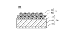
- FIG. 3 is a partially enlarged view of the recording layer of the magnetic recording medium according to the first embodiment. It is a figure which shows typically the laminated
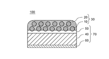
- FIG. 6 is a partially enlarged view of a recording layer of the magnetic recording medium according to the second embodiment.
- a magnetic recording medium 100 according to the first embodiment of the present invention includes a recording layer 30 including a plurality of magnetic particles 10 including a hard magnetic material 15 and a soft magnetic material 20 in contact with the plurality of magnetic particles 10, and a flexible layer. And a support layer 70 that supports the recording layer 30.
- the recording layer 30 includes the magnetic particles 10 including the supporting hard magnetic material 15 and the soft magnetic material 20, the recording layer 30 may be referred to as a composite magnetic material.
- the hard magnetic body 15 of the present embodiment contains ⁇ iron oxide.
- the magnetic particles 10 of the present embodiment contain ⁇ iron oxide as a main component.
- the ⁇ iron oxide contained in the magnetic particles 10 of the present embodiment includes a case where ⁇ -Fe 2 O 3 is represented by a composition formula. In the present specification, the main component is assumed to be more than 50% by weight.
- ⁇ iron oxide includes a form containing a substitution metal substituting iron.
- a substitution metal includes at least one of Co, Ni, Ti, and Ga. Therefore, the ⁇ iron oxide contained in the magnetic particles 10 may be described as ⁇ -P x Q y R z Fe (2-3x-1.5yz) O 3 .
- P, Q, and R each represent a monovalent, divalent, and trivalent metal, and parameters x, y, and z are 0 ⁇ x ⁇ 1.5, 0 ⁇ y ⁇ 2/3, and 0 ⁇ z ⁇ 2. , 0 ⁇ 3x ⁇ 1.5y ⁇ z ⁇ 2.
- the magnetic particles 10 including the ⁇ iron oxide particles included in the recording layer 30 are magnetic particles exhibiting a high coercive force Hc
- the magnetic recording medium containing the ⁇ iron oxide particles alone has a too large coercive force Hc. It may be difficult to record.
- the magnetization Br (remanent magnetization) is small, so that the signal-to-noise ratio (SNR) during recording/reproduction may be reduced. Therefore, the soft magnetic body 20 is arranged to supplement the magnetization Br that is insufficient when only the magnetic particles 10 are used as the magnetic recording layer, and exchange coupling by contacting with the plurality of magnetic particles 10 including the hard magnetic body 15. Is playing.
- the soft magnetic body 20 of the present embodiment covers the magnetic particles 10 so as to bridge the plurality of magnetic particles 10 that include the hard magnetic body 15 and are bonded to each other by sintering.
- the soft magnetic body 20 of the present embodiment covers the plurality of magnetic particles 10 so that the plurality of magnetic particles 10 are sandwiched between the soft magnetic body 20 and the support layer 70. It is also said that the soft magnetic body 20 covers the plurality of magnetic particles 10 on the side opposite to the surface where the magnetic particles 10 face the support layer 70.
- the soft magnetic body 20 of the present embodiment contains ⁇ -Fe as a main component.
- the soft magnetic body 20 may contain iron in another crystalline form such as ⁇ -Fe in the range where exchange coupling with the magnetic particles 10 is possible.
- the soft magnetic body 20 may contain amorphous iron having no crystallinity other than ⁇ -Fe.
- the recording layer 30 may contain additives such as a binder, a lubricant, an abrasive and a rust preventive.
- the layer thickness of the soft magnetic body 20 is increased or the content of the soft magnetic body 20 with respect to the hard magnetic body 15 is increased, the magnetization Br of the recording layer 30 increases and the coercive force Hc decreases.
- the concentration ratio of [soft magnetic material 20]/[hard magnetic material 15] satisfies the predetermined upper limit
- the effect of increasing the magnetization is greater than the decrease of the coercive force Hc. That is, when the relative content [soft magnetic body 20]/[hard magnetic body 15] of the soft magnetic body 20 is not more than the upper limit, the effect of increasing the magnetization Br can be prioritized.
- the layer thickness of the soft magnetic body 20 is preferably 500 nm or less, more preferably 200 nm or less.
- an optimum thickness can be appropriately selected from design values such as the characteristics of the magnetic head, the recording magnetization amount, and the coercive force.
- the recording layer 30 may contain a binder (not shown) for the purpose of improving the binding property between the magnetic particles 10 or for promoting the adhesion between the magnetic particles 10 and the soft magnetic body 20. ..
- the binder may be a homopolymer or a copolymer.
- the binder contained in the recording layer 30 is selected from polyurethane resin, polyester resin, polyamide resin, vinyl chloride resin, epoxy resin, phenoxy resin and polyvinyl acetal.
- the recording layer 30 can also be selected from an acrylic resin copolymerized with styrene, acrylonitrile, methyl methacrylate and the like, a cellulose resin such as nitrocellulose, and a polyvinyl alkaryl resin such as polyvinyl butyral. Furthermore, the recording layer 30 can be used by mixing a plurality of resins.
- the recording layer 30 is particularly preferably made of polyurethane resin, acrylic resin, cellulose resin and vinyl chloride resin.
- the recording layer 30 may be added with additives as required.
- the additive applied to the recording layer 30 include an abrasive, a lubricant, a dispersant, a dispersion aid, an antifungal agent, an antistatic agent, an antioxidant, and carbon black.
- the recording layer 30 includes a form containing a curing agent and a plasticizer.
- the support layer 70 supports the recording layer 30 so that the laminated body of the support layer 70 and the recording layer 30 has flexibility.
- the magnetic recording medium 100 is formed as a laminated body having flexibility, it becomes possible to wind the magnetic recording medium 100 on a reel, thereby increasing the recording capacity, portability and storability. Etc. can be improved. Further, it becomes possible to continue to apply a tension for pressing the magnetic recording medium 100 to the magnetic head during an operation such as recording and reproducing, and there is an effect that the magnetic head and the recording medium 100 slide stably during such an operation.
- the support layer 70 has a flexibility to stably support the recording layer 30 even if the support layer 70 is deformed by an external force.
- the support layer 70 has tensile strength, chemical stability with respect to environment, thermal stability, insensitivity to magnetic field, layer thickness, surface roughness, and antistatic property in consideration of portability of the recording medium 100, scanning form, and the like.
- the material and dimension can be selected in consideration of conductivity for the above.
- the support layer 70 includes a form that is a resin layer that does not exhibit magnetism, and such a configuration can reduce a magnetic field that becomes a background and affects the recording layer 30.
- Embodiments that do not exhibit magnetism include paramagnetism.
- the aspect which does not exhibit magnetism may be paraphrased as nonmagnetic.
- the support layer 70 of the present embodiment includes a substrate 40 made of a flexible resin, an intermediate layer 50 having adhesiveness or plastic deformability for supporting the recording layer 30, a winding property, and a support layer 70. And a back layer 60 that provides a peeling property that reduces sticking between the recording layer 30 and the recording layer 30.
- the base material 40 is a flexible, long film, and can be in the form of a roll.
- polyesters, polyolefins, cellulose derivatives, vinyl resins, polyimides, polyamides, metals, ceramics and the like are selected.
- Polyethylene terephthalate PET is selected for polyesters, and polyethylene, polypropylene, etc. are selected for polyolefins.
- the cellulose derivative is selected from cellulose triacetate, cellulose diacetate, cellulose butyrate and the like
- the vinyl resin is selected from polyvinyl chloride, polyvinylidene chloride and the like.
- the metal a paramagnetic metal or alloy such as titanium or aluminum is selected.
- Alumina or the like formed from a green sheet is selected as the ceramic.
- a thin film containing an oxide of Al or Cu may be disposed on at least one of the front and back surfaces of the base material 40 in order to increase the mechanical strength of the base material 40.
- the back layer 60 preferably contains carbon black and inorganic powder.
- the layer thickness of the back surface layer is preferably 0.9 ⁇ m or less, and more preferably 0.1 ⁇ m or more and 0.7 ⁇ m or less.
- the magnetic recording medium 100 of this embodiment can be manufactured by a manufacturing method including at least the following steps 1 and 2.
- Step 1 Laminated body in which a support layer 70 having flexibility and a recording layer 30 including a plurality of magnetic particles 10 including a hard magnetic body 15 and a soft magnetic body 20 in contact with the plurality of magnetic particles 10 are laminated.
- Step 2 Magnetic field applying step of magnetizing the magnetic particles 10 in a predetermined direction by an external magnetic field applied from the outside of the laminated body
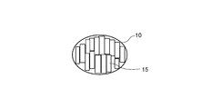
- the magnetic particle 10 is an aspherical body including a long axis and a short axis, and the plurality of magnetic particles 10 include a form in which the long axis is oriented in a predetermined direction as shown in FIG.
- the predetermined direction may coincide with the direction along the easy axis of magnetization.
- the soft magnetic material 20 may be magnetized not only by the magnetic particles 10 but also by the external magnetic field.
- the magnetic particles 10 containing ⁇ iron oxide as the hard magnetic material 15 are produced by producing nanoparticles of iron oxide or iron hydroxide using a chemical process in a solution and heating the produced nanoparticles in an oxidizing atmosphere. can get.
- the chemical process in the solution can be obtained, for example, by subjecting precursor particles formed by a reverse micelle method or a sol-gel method using iron nitrate hydrate as a starting material to heat treatment in an oxidizing atmosphere.
- the method of manufacturing the magnetic recording medium 100 according to the present embodiment includes a support layer 70 having flexibility, a plurality of magnetic particles 10 including the hard magnetic material 15, and a soft magnetic material 20 in contact with the plurality of magnetic particles 10.
- the recording layer 30 and the recording layer 30 are laminated to form a laminated body.
- the method for manufacturing the magnetic recording medium 100 includes a magnetic field applying step of magnetizing the magnetic particles 10 including the hard magnetic material 15 in a predetermined direction by an external magnetic field applied from the outside of the stacked body.
- the magnetic field applying step can be performed after the step of forming the laminated body.
- 1B and 2B are partially enlarged views of the recording layer 30.
- the magnetic particles 10 are magnetized in the vertical direction of the paper surface.
- the hard magnetic material 15 contained in the magnetic particles 10 is oriented in the upper limit direction of the paper surface.
- the easy axis of magnetization in the magnetic domain due to the application of the magnetic field can be identified by measuring the magnetic characteristics while varying the direction and strength of the external magnetization and taking the squareness ratio.
- 1B and 2B show a mode in which the magnetization direction is aligned with the short axis of the magnetic particle 10.
- a form in which the shape of the magnetic particles 10 and the magnetization direction do not necessarily match is included as a modification of the present embodiment.
- Step of preparing the material for the support layer A backing layer 60 is provided and a tape-shaped substrate 40 is prepared.
- the recording layer coating material is prepared by kneading and dispersing the magnetic particles 10 containing ⁇ iron oxide and the additive substance in a solvent.
- the additive substance includes conductive particles and a binder.
- the recording layer 30 is a composite of a hard magnetic material and a soft magnetic material in which the soft magnetic material 20 is contained as the binder matrix of the magnetic particles 10, the soft magnetic material is kneaded and dispersed in the coating material for the recording layer.
- the solvent used for the coating material for the recording layer is selected in consideration of the dispersibility of the magnetic particles 10 and the added substance, and examples thereof include a ketone solvent, an alcohol solvent, an ester solvent, an ether solvent, an aromatic solvent, and a halogen.
- a solvent containing a hydrocarbon and the like are included. These may be used alone or may be appropriately mixed and used.
- the intermediate layer 50 is formed on the base material 40 by applying the intermediate layer coating material to the surface of the base material 40 on which the back surface layer 60 is not formed and drying it. Through this step and the step of preparing the material for the support layer, the support layer 70 having flexibility is created.
- the magnetic particles 10 are formed on the intermediate layer 50 by applying the coating material for the recording layer on the intermediate layer 50 and drying it. Subsequently, the soft magnetic body 20 is formed on the surface on which the magnetic particles 10 are arranged, and the recording layer 30 is formed. This step is in other words the step of stacking the recording layer 30 on the support layer 70.
- the soft magnetic material 20 can be deposited on the magnetic particles 10 by using a sputtering method or a vacuum evaporation method. It is preferable to form the soft magnetic material 20 by a sputtering method because of its controllability of the layer thickness.
- the support layer 70 is wound around the cylindrical core and cured. Next, after calendering the support layer 70, the support layer 70 is cut into a predetermined width to obtain a long tape-shaped support layer 70 cut into a predetermined width.
- the predetermined width corresponds to the length of the core in the tube axis direction.
- the step of forming the back surface layer 60 may be performed after the calendar treatment.
- the present embodiment is related to the first embodiment in that the soft magnetic body 20 is a binder matrix that is in contact with the periphery of the magnetic particles 10 and binds the plurality of magnetic particles 10. It is different from the magnetic recording medium 100. In other words, the magnetic particles 10 of this embodiment are bound to each other via the soft magnetic body 20.
- Example 1 (Preparation of ⁇ -Fe2O3 particles) ⁇ -Fe 2 O 3 particles were produced by the following procedure.
- micelle solution (A) and micelle solution (B) were prepared as follows.
- micellar solution (B) was added dropwise to the micellar solution (A) while thoroughly stirring the micellar solution (A). After the dropping was completed, stirring was continued for 30 minutes.
- TEOS tetraethoxysilane
- ⁇ -Fe2O3 particle layer forming paint 6 g of vinyl chloride resin (30% cyclohexanone solution), 0.5 g of aluminum oxide powder, and 0.2 g of carbon black were weighed and sufficiently mixed with 10 g of the ⁇ -Fe2O3 particles produced as described above.
- the intermediate layer 50 and the recording layer 30 were formed as follows on the polyethylene naphthalate film (PEN film) which is a non-magnetic support.
- PEN film polyethylene naphthalate film
- the intermediate layer 50 was formed on the PEN film by applying and drying the intermediate layer 50 forming coating material on the PEN film having a thickness of 6 ⁇ m which is a non-magnetic support.
- the recording layer 30 forming coating material was applied onto the intermediate layer 50 and dried to form the recording layer 30 on the intermediate layer 50. The drying was performed in a coil that generates a magnetic field of 6 kOe, and the ⁇ -Fe2O3 particles were fixed while being aligned in the direction along the easy axis of magnetization.
- the PEN film on which the intermediate layer 50 and the recording layer 30 were formed was calendered to smooth the ⁇ -Fe2O3 particle layer.
- the average thickness of the intermediate layer 50 after calendering was 1 ⁇ m, and the average thickness of the ⁇ -Fe 2 O 3 particle layer was in the range of 20 to 50 nm.
- an Fe film was formed as a soft magnetic material on the ⁇ -Fe2O3 particle layer by a sputtering method (DC magnetron sputtering apparatus).
- a sputtering method DC magnetron sputtering apparatus.
- the PEN film on which the ⁇ -Fe 2 O 3 particle layer was formed was placed in a vacuum chamber, and vacuum evacuation was performed until the degree of vacuum reached 3 ⁇ 10 ⁇ 4 Pa.
- the pressure was adjusted to 0.5 Pa.
- pre-sputtering was performed at a discharge power of 100 W for 3 minutes, and then an Fe film was deposited to 200 nm on the ⁇ -Fe 2 O 3 particle layer for 1 minute to form the recording layer 30.
- a fluorine-based lubricant was applied on the recording layer 30 to form a top coat layer.
- the PEN film on which the intermediate layer 50, the recording layer 30, and the back layer 60 are formed as described above is cut into a width of 0.5 inch (12.65 mm) to obtain a magnetic tape as a magnetic recording medium. It was
- the measurement magnetic field was set at 50 kOe as a magnetic field sufficient to saturate the hysteresis curve of the magnetic tape. Since the obtained hysteresis curve includes background noise other than that of the recording layer 30, the hysteresis curve of only the recording layer 30 is obtained by linearly approximating the area where the hysteresis curve is saturated and subtracting from the hysteresis curve.
- the magnetization upon application of 50 kOe was calculated as saturation magnetization Ms(emu) and residual magnetization Mr(emu) to obtain the squareness ratio (Mr/Ms) of the magnetic signal. Further, the magnetic field at which the magnetization is zero was defined as the coercive force (Oe).
- the PEN film having the intermediate layer 50, the recording layer 30 having only the ⁇ -Fe2O3 particle layer, and the back layer 60 formed thereon was cut into a 0.5 inch (12.65 mm) width, and magnetic recording was performed. A magnetic tape as a medium was obtained.
- the measurement magnetic field was 50 kOe as a magnetic field sufficient to saturate the MH curve of the magnetic tape. Since the obtained MH curve contains background noise other than that of the recording layer 30, the MH curve of only the recording layer 30 is obtained by linearly approximating the area where the MH curve is saturated and subtracting it from the MH curve. And The magnetization upon application of 50 kOe was calculated as saturation magnetization Ms(emu) and residual magnetization Mr(emu) to obtain the squareness ratio (Mr/Ms) of the magnetic signal.
- Example 2 to 5 A magnetic tape was produced using the same ⁇ -Fe2O3 particle layer forming coating material and intermediate layer 50 forming coating material as in Example 1. However, a magnetic tape was produced by setting the thickness of the Fe film of the soft magnetic material to 20 to 100 nm and the other configurations being the same as in Example 1, and the magnetic characteristics were evaluated.
- Example 6 to 9 Using the production method of ⁇ -Fe2O3 particles of Example 1 as a basic production method, ⁇ -Fe2O3 particles in which a part of Fe element was replaced with another metal element (Co, Ni, Ti or Ga) were synthesized. For each metal element, cobalt nitrate hydrate is used for Co, nickel nitrate hydrate is used for Ni, titanium sulfate hydrate is used for Ti, and gallium nitrate hydrate is used for Ga. % Replaced.
- Example 2 a coating material for forming an ⁇ -Fe2O3 particle layer and a coating material for forming the intermediate layer 50 were prepared, and a magnetic tape was prepared by depositing a Fe film to a thickness of 200 nm on the ⁇ -Fe2O3 particle layer to prepare a magnetic tape. The characteristics were evaluated.
- ⁇ -Fe2O3 particles were produced by substituting a part of Fe element of ⁇ -Fe2O3 particles with another metal element (Co, Ni, Ti or Ga), and a magnetic tape having only the ⁇ -Fe2O3 layer as a recording layer was prepared to produce a magnetic tape. The characteristics were evaluated. The amount of substitution of the metal element was selected such that the coercive force of the ⁇ -Fe2O3 particles was about 3000 Oe.
Landscapes
- Magnetic Record Carriers (AREA)
- Manufacturing Of Magnetic Record Carriers (AREA)
Abstract
A magnetic recording medium 100 according to the present invention is provided with: a recording layer 30 which contains a plurality of magnetic particles 10 that contain hard magnetic bodies 15 and a soft magnetic body 20 that is in contact with the plurality of magnetic particles 10; and a support layer 70 which is flexible and supports the recording layer 30.
Description
本発明は、磁気記録媒体に関する。特に、硬質磁性体と軟質磁性体の少なくとも一方が他方に分散された複合磁性体を記録層に持つ磁気記録媒体に関する。
The present invention relates to a magnetic recording medium. In particular, it relates to a magnetic recording medium having a composite magnetic body in which at least one of a hard magnetic body and a soft magnetic body is dispersed in the other, in a recording layer.
従来、磁気記録媒体は、シート状の樹脂基材上に磁性体を含む記録層を積層した磁気フィルム、磁気ディスクが知られている。かかる記録媒体は、磁気ヘッドに対して相対移動することで、時系列データに対応した磁区として記録層に形成し、再生することが可能となる。従って、微細化した磁性粒子を高密度に記録層に配置することにより記録密度を高める技術が求められている。特開2016-130208号公報は、平均粒径10-30nmのε-Fe2O3を含有する鉄系の磁性粒子を配置した記録層を備える磁気記録媒体を開示している。特開2016-130208号公報では、鉄系の磁性粒子をウレタン等の樹脂バインダーとともに塗料化したビヒクルをベースフィルムに塗布して磁気記録フィルムを形成すること、塗布直後に外部磁場により磁場配向させること、を開示している。
Conventionally, as a magnetic recording medium, a magnetic film and a magnetic disk in which a recording layer containing a magnetic material is laminated on a sheet-shaped resin base material are known. By moving relative to the magnetic head, such a recording medium can be formed in the recording layer as a magnetic domain corresponding to time-series data and can be reproduced. Therefore, there is a demand for a technique for increasing recording density by arranging finely divided magnetic particles in the recording layer with high density. Japanese Unexamined Patent Publication No. 2016-130208 discloses a magnetic recording medium provided with a recording layer in which iron-based magnetic particles containing ε-Fe2O3 having an average particle diameter of 10-30 nm are arranged. In JP-A-2016-130208, a vehicle in which iron-based magnetic particles are coated with a resin binder such as urethane is applied to a base film to form a magnetic recording film, and magnetic field orientation is performed by an external magnetic field immediately after application. , Are disclosed.
磁気記録媒体は、高い保磁力Hcおよび高い残留磁束密度(残留磁化)Brを有する電磁変換特性が求められる。高い保持力Hcは、高密度に実装しても隣接する磁区の影響により磁化が反転し難くなる効果をもたらす。高い磁化Brは、磁区が小さくなった場合にも磁気ヘッドが磁電変換する際のSN比を高くすることを可能とする。
Magnetic recording media are required to have electromagnetic conversion characteristics having high coercive force Hc and high residual magnetic flux density (residual magnetization) Br. The high coercive force Hc brings about an effect that the magnetization is not easily inverted due to the influence of the adjacent magnetic domains even if the high coercive force is mounted. The high magnetization Br makes it possible to increase the SN ratio when the magnetic head performs magnetoelectric conversion even when the magnetic domain becomes small.
一方で、特開2016-130208号公報に記載の記録層は、磁気記録に寄与する機能成分は鉄系の磁性粒子のみを含む形態であったため、鉄系の磁性粒子が呈する低い磁化特性により磁気記録フィルムの磁化Brを高くし難いという問題があった。なお、本願明細書において、保持力Hcは、単位にOeを用いる場合が含まれ、残留磁束密度Brは単位にemu/gを用いる場合、磁化Brと言い換える場合が含まれる。
On the other hand, the recording layer described in Japanese Unexamined Patent Application Publication No. 2016-130208 has a form in which the functional component that contributes to magnetic recording includes only iron-based magnetic particles. There is a problem that it is difficult to increase the magnetization Br of the recording film. In the specification of the application, the coercive force Hc includes a case where Oe is used as a unit, and the residual magnetic flux density Br includes a case where it is paraphrased as a magnetization Br when emu/g is used as a unit.
本発明の目的は、簡易な手法により、高い保持力Hcと高い磁化Brを呈する磁気記録媒体を提供することにある。
An object of the present invention is to provide a magnetic recording medium exhibiting high coercive force Hc and high magnetization Br by a simple method.
本発明の第一に係る磁気記録媒体は、硬質磁性体を含む複数の磁性粒子と前記複数の磁性粒子に接する軟質磁性体とを含む記録層と、可橈性を呈し前記記録層を支持する支持層と、を備えることを特徴とする。
A magnetic recording medium according to the first aspect of the present invention, a recording layer including a plurality of magnetic particles containing a hard magnetic material and a soft magnetic material in contact with the plurality of magnetic particles, and exhibits flexibility to support the recording layer. And a support layer.
また、本発明の第二に係る磁気記録媒体の製造方法は、可橈性を有する支持層と、硬質磁性体を含む複数の磁性粒子と前記複数の磁性粒子に接する軟質磁性体とを含む記録層と、を積層し積層体を形成する工程と、前記積層体の外部より印加する外部磁場により、前記軟質磁性体および前記磁性粒子を所定方向に磁化する磁場印加工程と、を有することを特徴とする。
Further, the method for producing a magnetic recording medium according to the second aspect of the present invention is a recording method comprising a support layer having flexibility, a plurality of magnetic particles containing a hard magnetic material, and a soft magnetic material in contact with the plurality of magnetic particles. And a magnetic field applying step of magnetizing the soft magnetic material and the magnetic particles in a predetermined direction by an external magnetic field applied from the outside of the laminated body. And
以下、本発明の実施の形態について説明する。なお、本発明は、以下の実施の形態に限定されるものではなく、本発明の趣旨を逸脱しない範囲で、当業者の通常の知識に基づいて、以下の実施の形態に対して適宜変更、改良等が加えられたものも本発明の範囲に含まれる。
Hereinafter, embodiments of the present invention will be described. The present invention is not limited to the following embodiments, and is appropriately modified from the following embodiments based on the ordinary knowledge of those skilled in the art without departing from the spirit of the present invention. Those with improvements and the like are also included in the scope of the present invention.
<第1の実施形態>
本発明の第1の実施形態に係る磁気記録媒体100は、硬質磁性体15を含む複数の磁性粒子10と複数の磁性粒子10に接する軟質磁性体20とを含む記録層30と、可橈性を呈し記録層30を支持する支持層70と、を備える。 <First Embodiment>
Amagnetic recording medium 100 according to the first embodiment of the present invention includes a recording layer 30 including a plurality of magnetic particles 10 including a hard magnetic material 15 and a soft magnetic material 20 in contact with the plurality of magnetic particles 10, and a flexible layer. And a support layer 70 that supports the recording layer 30.
本発明の第1の実施形態に係る磁気記録媒体100は、硬質磁性体15を含む複数の磁性粒子10と複数の磁性粒子10に接する軟質磁性体20とを含む記録層30と、可橈性を呈し記録層30を支持する支持層70と、を備える。 <First Embodiment>
A
記録層30は、支持している硬質磁性体15を含む磁性粒子10と、軟質磁性体20と、を含むことから、複合磁性体と表記される場合がある。本実施形態の硬質磁性体15はε酸化鉄を含有している。本実施形態の磁性粒子10は、ε酸化鉄を主成分として含有すると換言される。また、本実施形態の磁性粒子10に含まれるε酸化鉄は、ε-Fe2O3と組成式で表記される場合が含まれる。本願明細書において、主成分は、重量パーセントにおいて50%より大の成分であることとする。
Since the recording layer 30 includes the magnetic particles 10 including the supporting hard magnetic material 15 and the soft magnetic material 20, the recording layer 30 may be referred to as a composite magnetic material. The hard magnetic body 15 of the present embodiment contains ε iron oxide. In other words, the magnetic particles 10 of the present embodiment contain ε iron oxide as a main component. In addition, the ε iron oxide contained in the magnetic particles 10 of the present embodiment includes a case where ε-Fe 2 O 3 is represented by a composition formula. In the present specification, the main component is assumed to be more than 50% by weight.
また、ε酸化鉄は、鉄を置換する置換金属を含む形態が含まれる。かかる置換金属は、Co、Ni、Ti、Gaの少なくとも1つが含まれる。従って、磁性粒子10に含まれるε酸化鉄は、ε-PxQyRzFe(2-3x-1.5y-z)O3 で記述される場合がある。ここで、P、Q、Rはそれぞれ1価2価3価の金属を表し、パラメータx、y、zは、0≦x<1.5、0≦y<2/3、0≦z<2、0≦3x-1.5y-z<2を満たす数である。
Further, ε iron oxide includes a form containing a substitution metal substituting iron. Such a substitution metal includes at least one of Co, Ni, Ti, and Ga. Therefore, the ε iron oxide contained in the magnetic particles 10 may be described as ε-P x Q y R z Fe (2-3x-1.5yz) O 3 . Here, P, Q, and R each represent a monovalent, divalent, and trivalent metal, and parameters x, y, and z are 0≦x<1.5, 0≦y<2/3, and 0≦z<2. , 0≦3x−1.5y−z<2.
また、記録層30が備えるε酸化鉄粒子を含む磁性粒子10は高い保磁力Hcを呈する磁性粒子であるものの、ε酸化鉄粒子を単体で含有する磁気記録媒体は、保磁力Hcが大きすぎて記録が困難となる場合がある。また、ε酸化鉄粒子を単体で含有する磁気記録媒体は、磁化Br(残留磁化)が小さいため記録・再生時の信号とノイズの比(SNR)が低下する場合がある。そこで、軟質磁性体20は、磁性粒子10のみを磁気記録層とした場合に不足する磁化Brを補うために配置されており、硬質磁性体15を含む複数の磁性粒子10と接することで交換結合をなしている。本実施形態の軟質磁性体20は、硬質磁性体15を含み焼結により互いに接合した複数の磁性粒子10を橋渡しするように磁性粒子10を被覆している。本実施形態の軟質磁性体20は、複数の磁性粒子10が軟質磁性体20と支持層70とに挟まれるように、複数の磁性粒子を被覆していると換言される。また、軟質磁性体20は、磁性粒子10が支持層70に対向する面とは反対側において、複数の磁性粒子10を被覆しているとも換言される。
Further, although the magnetic particles 10 including the ε iron oxide particles included in the recording layer 30 are magnetic particles exhibiting a high coercive force Hc, the magnetic recording medium containing the ε iron oxide particles alone has a too large coercive force Hc. It may be difficult to record. Further, in a magnetic recording medium containing ε iron oxide particles alone, the magnetization Br (remanent magnetization) is small, so that the signal-to-noise ratio (SNR) during recording/reproduction may be reduced. Therefore, the soft magnetic body 20 is arranged to supplement the magnetization Br that is insufficient when only the magnetic particles 10 are used as the magnetic recording layer, and exchange coupling by contacting with the plurality of magnetic particles 10 including the hard magnetic body 15. Is playing. The soft magnetic body 20 of the present embodiment covers the magnetic particles 10 so as to bridge the plurality of magnetic particles 10 that include the hard magnetic body 15 and are bonded to each other by sintering. In other words, the soft magnetic body 20 of the present embodiment covers the plurality of magnetic particles 10 so that the plurality of magnetic particles 10 are sandwiched between the soft magnetic body 20 and the support layer 70. It is also said that the soft magnetic body 20 covers the plurality of magnetic particles 10 on the side opposite to the surface where the magnetic particles 10 face the support layer 70.
本実施形態の軟質磁性体20は、α-Feを主成分として含有している。軟質磁性体20は、磁性粒子10と交換結合ができる範囲において、β―Fe等の他の結晶形態の鉄を含む場合がある。軟質磁性体20はα―Fe以外に結晶性を呈さない非晶質鉄を含有してもよい。なお、記録層30は、結着剤、潤滑剤、研磨剤、防錆剤などの添加剤を含んでいてもよい。
The soft magnetic body 20 of the present embodiment contains α-Fe as a main component. The soft magnetic body 20 may contain iron in another crystalline form such as β-Fe in the range where exchange coupling with the magnetic particles 10 is possible. The soft magnetic body 20 may contain amorphous iron having no crystallinity other than α-Fe. The recording layer 30 may contain additives such as a binder, a lubricant, an abrasive and a rust preventive.
軟質磁性体20の層厚を厚くしたり、軟質磁性体20の硬質磁性体15に対する含有量を増大したりすると、記録層30は磁化Brが増大し保磁力Hcが低下する。しかしながら、[軟質磁性体20]/[硬質磁性体15]の濃度比が所定の上限を満たす範囲においては、保持力Hcの低下より磁化の増大効果がより大きい。すなわち、軟質磁性体20の相対含有量[軟質磁性体20]/[硬質磁性体15]が上限以下の場合は、磁化Brの増大効果を優先した形態とすることができる。この点において、軟質磁性体20の層厚は、500nm以下の厚さ、より好ましくは200nm以下の厚さとすることが好ましい。磁化Brは、磁気ヘッドの特性、記録磁化量、保磁力等の設計値から適宜最適な厚さを選択することができる。
When the layer thickness of the soft magnetic body 20 is increased or the content of the soft magnetic body 20 with respect to the hard magnetic body 15 is increased, the magnetization Br of the recording layer 30 increases and the coercive force Hc decreases. However, in the range where the concentration ratio of [soft magnetic material 20]/[hard magnetic material 15] satisfies the predetermined upper limit, the effect of increasing the magnetization is greater than the decrease of the coercive force Hc. That is, when the relative content [soft magnetic body 20]/[hard magnetic body 15] of the soft magnetic body 20 is not more than the upper limit, the effect of increasing the magnetization Br can be prioritized. In this respect, the layer thickness of the soft magnetic body 20 is preferably 500 nm or less, more preferably 200 nm or less. As the magnetization Br, an optimum thickness can be appropriately selected from design values such as the characteristics of the magnetic head, the recording magnetization amount, and the coercive force.
一方、記録層30は、磁性粒子10相互の結着性を向上させる目的か、磁性粒子10と軟質磁性体20との密着を促進する目的から、不図示の結着剤を含有することができる。結着剤は、ホモポリマーであってもコポリマー(共重合体)であってもよい。記録層30に含まれる結着剤は、ポリウレタン樹脂、ポリエステル樹脂、ポリアミド樹脂、塩化ビニル樹脂、エポキシ樹脂、フェノキシ樹脂、ポリビニルアセタールから選択される。また、記録層30は、スチレン、アクリロニトリル、メチルメタクリレート等を共重合したアクリル樹脂、ニトロセルロース等のセルロース樹脂、ポリビニルブチラール等のポリビニルアルキラール樹脂等から選択されることもできる。さらにまた、記録層30は、複数の樹脂を混合して用いることができる。記録層30は、ポリウレタン樹脂、アクリル樹脂、セルロース樹脂および塩化ビニル樹脂が特に好ましい。
On the other hand, the recording layer 30 may contain a binder (not shown) for the purpose of improving the binding property between the magnetic particles 10 or for promoting the adhesion between the magnetic particles 10 and the soft magnetic body 20. .. The binder may be a homopolymer or a copolymer. The binder contained in the recording layer 30 is selected from polyurethane resin, polyester resin, polyamide resin, vinyl chloride resin, epoxy resin, phenoxy resin and polyvinyl acetal. Further, the recording layer 30 can also be selected from an acrylic resin copolymerized with styrene, acrylonitrile, methyl methacrylate and the like, a cellulose resin such as nitrocellulose, and a polyvinyl alkaryl resin such as polyvinyl butyral. Furthermore, the recording layer 30 can be used by mixing a plurality of resins. The recording layer 30 is particularly preferably made of polyurethane resin, acrylic resin, cellulose resin and vinyl chloride resin.
その他に、記録層30は、必要に応じて添加剤を加えることができる。記録層30に適用される添加剤は、研磨剤、潤滑剤、分散剤、分散助剤、防黴剤、帯電防止剤、酸化防止剤、カーボンブラック等を挙げることができる。また、記録層30は、硬化剤、可塑剤を含む形態が含まれる。
In addition, the recording layer 30 may be added with additives as required. Examples of the additive applied to the recording layer 30 include an abrasive, a lubricant, a dispersant, a dispersion aid, an antifungal agent, an antistatic agent, an antioxidant, and carbon black. Further, the recording layer 30 includes a form containing a curing agent and a plasticizer.
一方、支持層70は、支持層70と記録層30との積層体が可橈性を有するように、記録層30を支持している。このように積層体としての磁気記録媒体100が可橈性を有する構成とすることにより、磁気記録媒体100をリールに巻き取る形態とすることが可能となり、記録容量の増大、可搬性や保管性等の向上が図られる。また、記録、再生等の動作時に、磁気記録媒体100を磁気ヘッドに押し付けるテンションを印加し続けることが可能となり、かかる動作時の磁気ヘッドと記録媒体100との摺動が安定する効果を持つ。
On the other hand, the support layer 70 supports the recording layer 30 so that the laminated body of the support layer 70 and the recording layer 30 has flexibility. By thus forming the magnetic recording medium 100 as a laminated body having flexibility, it becomes possible to wind the magnetic recording medium 100 on a reel, thereby increasing the recording capacity, portability and storability. Etc. can be improved. Further, it becomes possible to continue to apply a tension for pressing the magnetic recording medium 100 to the magnetic head during an operation such as recording and reproducing, and there is an effect that the magnetic head and the recording medium 100 slide stably during such an operation.
支持層70は、外力により支持層70が変形しても安定して記録層30を支持し続けるための可橈性を有している。支持層70は、記録媒体100の可搬性、走査形態等を考慮して、引張強度、環境に対する化学的安定性、熱的安定性、磁場に対する不敏感性、層厚、表面粗さ、帯電防止の為の導電性、等を考慮して材料、ディメンジョン選択することができる。支持層70は、磁性を呈しない樹脂層である形態が含まれ、このような構成により記録層30に影響を及ぼすバックグラウンドとなる磁場を低減できる。磁性を呈しないと態様は、常磁性が含まれる。磁性を呈しない態様は、非磁性と言い換える場合がある。
The support layer 70 has a flexibility to stably support the recording layer 30 even if the support layer 70 is deformed by an external force. The support layer 70 has tensile strength, chemical stability with respect to environment, thermal stability, insensitivity to magnetic field, layer thickness, surface roughness, and antistatic property in consideration of portability of the recording medium 100, scanning form, and the like. The material and dimension can be selected in consideration of conductivity for the above. The support layer 70 includes a form that is a resin layer that does not exhibit magnetism, and such a configuration can reduce a magnetic field that becomes a background and affects the recording layer 30. Embodiments that do not exhibit magnetism include paramagnetism. The aspect which does not exhibit magnetism may be paraphrased as nonmagnetic.
本実施形態の支持層70は、可橈性を有する樹脂で構成される基材40、記録層30を支持するための接着性または塑性変形性を備える中間層50、巻き取り性、支持層70と記録層30との固着を低減する剥離性を与える背面層60を備えている。
The support layer 70 of the present embodiment includes a substrate 40 made of a flexible resin, an intermediate layer 50 having adhesiveness or plastic deformability for supporting the recording layer 30, a winding property, and a support layer 70. And a back layer 60 that provides a peeling property that reduces sticking between the recording layer 30 and the recording layer 30.
基材40は、可撓性を有する長尺状のフィルムであって、ロール形態をとることが可能である。基材40の材料としては、ポリエステル類、ポリオレフィン類、セルロース誘導体、ビニル系樹脂、ポリイミド、ポリアミド、金属、セラミック等が選択される。
The base material 40 is a flexible, long film, and can be in the form of a roll. As the material of the base material 40, polyesters, polyolefins, cellulose derivatives, vinyl resins, polyimides, polyamides, metals, ceramics and the like are selected.
ポリエステル類はポリエチレンテレフタレートPETが選択され、ポリオレフィン類はポリエチレン、ポリプロピレン等が選択される。セルロース誘導体はセルローストリアセテート、セルロースダイアセテート、セルロースブチレート等から選択され、ビニル系樹脂はポリ塩化ビニル、ポリ塩化ビニリデン等から選択される。金属はチタン、アルミニウム等の常磁性の金属または合金が選択される。セラミックはグリーンシートから成形されるアルミナ等が選択される。支持層は、基材40の機械的強度を高めるために、AlまたはCuの酸化物を含む薄膜を基材40の表裏の少なくともいずれかに配置しても良い。
Polyethylene terephthalate PET is selected for polyesters, and polyethylene, polypropylene, etc. are selected for polyolefins. The cellulose derivative is selected from cellulose triacetate, cellulose diacetate, cellulose butyrate and the like, and the vinyl resin is selected from polyvinyl chloride, polyvinylidene chloride and the like. As the metal, a paramagnetic metal or alloy such as titanium or aluminum is selected. Alumina or the like formed from a green sheet is selected as the ceramic. As the support layer, a thin film containing an oxide of Al or Cu may be disposed on at least one of the front and back surfaces of the base material 40 in order to increase the mechanical strength of the base material 40.
背面層60は、カーボンブラックおよび無機粉末が含有されていることが好ましい。背面層の層厚は、0.9μm以下であることが好ましく、0.1μm以上0.7μm以下であることがより好ましい。
The back layer 60 preferably contains carbon black and inorganic powder. The layer thickness of the back surface layer is preferably 0.9 μm or less, and more preferably 0.1 μm or more and 0.7 μm or less.
基材40と記録層30との間に、磁性粒子10の基材40に対する密着性を担保する密着層、基材40と記録層30との物性の差を緩和する緩和層等の機能を有する中間層50を付加する形態が本実施形態の変形例に含まれる。
Between the base material 40 and the recording layer 30, it has a function of an adhesion layer for ensuring the adhesion of the magnetic particles 10 to the base material 40, a relaxation layer for relaxing the difference in the physical properties of the base material 40 and the recording layer 30, and the like. A mode in which the intermediate layer 50 is added is included in the modification of the present embodiment.
本実施形態の磁気記録媒体100は、以下の工程1、2を少なくとも含む製造方法により製造することができる。
(工程1)可橈性を有する支持層70と、硬質磁性体15を含む複数の磁性粒子10と複数の磁性粒子10に接する軟質磁性体20とを含む記録層30と、を積層し積層体を形成する工程
(工程2)積層体の外部より印加する外部磁場により、磁性粒子10を所定方向に磁化する磁場印加工程 Themagnetic recording medium 100 of this embodiment can be manufactured by a manufacturing method including at least the following steps 1 and 2.
(Step 1) Laminated body in which asupport layer 70 having flexibility and a recording layer 30 including a plurality of magnetic particles 10 including a hard magnetic body 15 and a soft magnetic body 20 in contact with the plurality of magnetic particles 10 are laminated. (Step 2) Magnetic field applying step of magnetizing the magnetic particles 10 in a predetermined direction by an external magnetic field applied from the outside of the laminated body
(工程1)可橈性を有する支持層70と、硬質磁性体15を含む複数の磁性粒子10と複数の磁性粒子10に接する軟質磁性体20とを含む記録層30と、を積層し積層体を形成する工程
(工程2)積層体の外部より印加する外部磁場により、磁性粒子10を所定方向に磁化する磁場印加工程 The
(Step 1) Laminated body in which a
なお、磁性粒子10は、長軸と短軸とを含む非球体であり、複数の磁性粒子10において、図1のように、長軸が所定方向に配向されている形態が含まれる。かかる所定方向には、磁化容易軸に沿った方向に一致する場合がある。また、本工程において、外部磁場による磁化は、磁性粒子10だけではなく軟質磁性体20が磁化される場合がある。
The magnetic particle 10 is an aspherical body including a long axis and a short axis, and the plurality of magnetic particles 10 include a form in which the long axis is oriented in a predetermined direction as shown in FIG. The predetermined direction may coincide with the direction along the easy axis of magnetization. In this step, the soft magnetic material 20 may be magnetized not only by the magnetic particles 10 but also by the external magnetic field.
次に、本実施形態に係る磁性粒子10の製造方法を、硬質磁性体15がε酸化鉄の例を用いて以下に説明する。ε酸化鉄を硬質磁性体15として含む磁性粒子10は、溶液中での化学的プロセスを用いて酸化鉄や水酸化鉄のナノ粒子を生成し、生成したナノ粒子を酸化雰囲気で加熱することで得られる。溶液中での化学的プロセスとしては、例えば、硝酸鉄水和物を出発原料とした逆ミセル法やゾルゲル法等で形成した前駆体粒子を酸化雰囲気中で加熱処理することで得られる。
Next, a method for manufacturing the magnetic particles 10 according to the present embodiment will be described below by using an example in which the hard magnetic body 15 is ε iron oxide. The magnetic particles 10 containing ε iron oxide as the hard magnetic material 15 are produced by producing nanoparticles of iron oxide or iron hydroxide using a chemical process in a solution and heating the produced nanoparticles in an oxidizing atmosphere. can get. The chemical process in the solution can be obtained, for example, by subjecting precursor particles formed by a reverse micelle method or a sol-gel method using iron nitrate hydrate as a starting material to heat treatment in an oxidizing atmosphere.
次に、本実施形態に係る磁気記録媒体100の製造方法について以下に説明する。
Next, a method for manufacturing the magnetic recording medium 100 according to this embodiment will be described below.
本実施形態に係る磁気記録媒体100の製造方法は、可橈性を有する支持層70と、硬質磁性体15を含む複数の磁性粒子10と複数の磁性粒子10に接する軟質磁性体20とを含む記録層30と、を積層し積層体を形成する工程を含む。
The method of manufacturing the magnetic recording medium 100 according to the present embodiment includes a support layer 70 having flexibility, a plurality of magnetic particles 10 including the hard magnetic material 15, and a soft magnetic material 20 in contact with the plurality of magnetic particles 10. The recording layer 30 and the recording layer 30 are laminated to form a laminated body.
本実施形態に係る磁気記録媒体100の製造方法は、積層体の外部より印加する外部磁場により、硬質磁性体15を含む磁性粒子10を所定方向に磁化する磁場印加工程を含む。磁場印加工程は、積層体を形成する工程の後に行うことができる。図1B及び図2Bは、記録層30の部分拡大図である。各実施形態において、磁性粒子10は、紙面の上下方向に磁化されている。磁性粒子10に含まれる硬質磁性体15は、紙面の上限方向に配向されていると換言される。磁場印加による磁区内の磁化容易軸は、外部磁化の方向、強さを可変しながら磁気特性を測定し、角型比をとることにより同定することができる。図1B及び図2Bでは磁性粒子10の短軸に磁化方向が揃っている形態を示している。しかしながら、磁性粒子10の形状と磁化方向とは必ずしも一致しない形態が本実施形態の変形例として含まれる。
The method for manufacturing the magnetic recording medium 100 according to the present embodiment includes a magnetic field applying step of magnetizing the magnetic particles 10 including the hard magnetic material 15 in a predetermined direction by an external magnetic field applied from the outside of the stacked body. The magnetic field applying step can be performed after the step of forming the laminated body. 1B and 2B are partially enlarged views of the recording layer 30. In each embodiment, the magnetic particles 10 are magnetized in the vertical direction of the paper surface. In other words, the hard magnetic material 15 contained in the magnetic particles 10 is oriented in the upper limit direction of the paper surface. The easy axis of magnetization in the magnetic domain due to the application of the magnetic field can be identified by measuring the magnetic characteristics while varying the direction and strength of the external magnetization and taking the squareness ratio. 1B and 2B show a mode in which the magnetization direction is aligned with the short axis of the magnetic particle 10. However, a form in which the shape of the magnetic particles 10 and the magnetization direction do not necessarily match is included as a modification of the present embodiment.
(支持層の材料を準備する工程)
背面層60を備えテープ状に成形された基材40を用意する。 (Step of preparing the material for the support layer)
Abacking layer 60 is provided and a tape-shaped substrate 40 is prepared.
背面層60を備えテープ状に成形された基材40を用意する。 (Step of preparing the material for the support layer)
A
(記録層の材料を準備する工程)
ε酸化鉄を含む磁性粒子10、添加物質を溶剤に混練、分散させることにより、記録層用塗料を作成する。添加物質は導電性粒子および結着剤等が含まれる。記録層30が、軟質磁性体20が磁性粒子10のバインダーマトリクスとして含まれる硬質磁性体と軟質磁性体との複合体の場合、記録層用塗料に軟質磁性体を混練、分散させておく。 (Process of preparing recording layer material)
The recording layer coating material is prepared by kneading and dispersing themagnetic particles 10 containing ε iron oxide and the additive substance in a solvent. The additive substance includes conductive particles and a binder. When the recording layer 30 is a composite of a hard magnetic material and a soft magnetic material in which the soft magnetic material 20 is contained as the binder matrix of the magnetic particles 10, the soft magnetic material is kneaded and dispersed in the coating material for the recording layer.
ε酸化鉄を含む磁性粒子10、添加物質を溶剤に混練、分散させることにより、記録層用塗料を作成する。添加物質は導電性粒子および結着剤等が含まれる。記録層30が、軟質磁性体20が磁性粒子10のバインダーマトリクスとして含まれる硬質磁性体と軟質磁性体との複合体の場合、記録層用塗料に軟質磁性体を混練、分散させておく。 (Process of preparing recording layer material)
The recording layer coating material is prepared by kneading and dispersing the
記録層用塗料に用いられる溶剤は、磁性粒子10、添加物質の分散性を考慮して選択され、例えば、ケトン系溶媒、アルコール系溶媒、エステル系溶媒、エーテル系溶媒、芳香族系溶媒、ハロゲン化炭化水素を含有する溶媒などが含まれる。これらは単独で用いてもよく、適宜混合して用いてもよい。かかる塗料の調整に用いられる混練装置は、例えば、連続二軸混練機、多段階で希釈可能な連続二軸混練機、ニーダー、加圧ニーダー、ロールニーダーなどの混練装置を用いることができる。また、上述の塗料調製に用いられる分散装置は、ロールミル、ボールミル、ホモジナイザー、超音波分散機などが選択される。
The solvent used for the coating material for the recording layer is selected in consideration of the dispersibility of the magnetic particles 10 and the added substance, and examples thereof include a ketone solvent, an alcohol solvent, an ester solvent, an ether solvent, an aromatic solvent, and a halogen. A solvent containing a hydrocarbon and the like are included. These may be used alone or may be appropriately mixed and used. As a kneading device used for preparing such a coating material, for example, a kneading device such as a continuous biaxial kneading machine, a continuous biaxial kneading machine capable of diluting in multiple stages, a kneader, a pressure kneader, or a roll kneader can be used. A roll mill, a ball mill, a homogenizer, an ultrasonic disperser, or the like is selected as the dispersing device used for the above-mentioned coating material preparation.
(中間層形成工程)
基材40の背面層60を形成していない面に、中間層用塗料を塗布して乾燥させることにより、基材40の上に中間層50を形成する。本工程と支持層の材料を準備する工程とにより、可橈性を有する支持層70が作成される。 (Intermediate layer forming step)
Theintermediate layer 50 is formed on the base material 40 by applying the intermediate layer coating material to the surface of the base material 40 on which the back surface layer 60 is not formed and drying it. Through this step and the step of preparing the material for the support layer, the support layer 70 having flexibility is created.
基材40の背面層60を形成していない面に、中間層用塗料を塗布して乾燥させることにより、基材40の上に中間層50を形成する。本工程と支持層の材料を準備する工程とにより、可橈性を有する支持層70が作成される。 (Intermediate layer forming step)
The
(積層工程、記録層形成工程)
中間層50の上に記録層用塗料を塗布して乾燥させることにより、磁性粒子10を中間層50の上に形成する。続いて、磁性粒子10が配置された面の上に軟質磁性体20を形成し記録層30を作成する。この工程は、支持層70の上に記録層30を積層する工程と換言される。 (Laminating step, recording layer forming step)
Themagnetic particles 10 are formed on the intermediate layer 50 by applying the coating material for the recording layer on the intermediate layer 50 and drying it. Subsequently, the soft magnetic body 20 is formed on the surface on which the magnetic particles 10 are arranged, and the recording layer 30 is formed. This step is in other words the step of stacking the recording layer 30 on the support layer 70.
中間層50の上に記録層用塗料を塗布して乾燥させることにより、磁性粒子10を中間層50の上に形成する。続いて、磁性粒子10が配置された面の上に軟質磁性体20を形成し記録層30を作成する。この工程は、支持層70の上に記録層30を積層する工程と換言される。 (Laminating step, recording layer forming step)
The
なお軟質磁性体20は、スパッタ法、真空蒸着法を用いて磁性粒子10の上に堆積させることができる。軟質磁性体20の層の層厚の制御性からスパッタ法で形成するのが好ましい。
The soft magnetic material 20 can be deposited on the magnetic particles 10 by using a sputtering method or a vacuum evaporation method. It is preferable to form the soft magnetic material 20 by a sputtering method because of its controllability of the layer thickness.
(ロール成形)
次に、支持層70を円管状のコアに巻き取り、硬化処理を行う。次に、支持層70に対してカレンダー処理を行った後、所定の幅に裁断し、所定の幅に裁断された長尺テープ状の支持層70を得る。所定の幅は、前述のコアの管軸方向における長さに相当する。なお、背面層60を形成する工程は、カレンダー処理後であってもよい。 (Roll forming)
Next, thesupport layer 70 is wound around the cylindrical core and cured. Next, after calendering the support layer 70, the support layer 70 is cut into a predetermined width to obtain a long tape-shaped support layer 70 cut into a predetermined width. The predetermined width corresponds to the length of the core in the tube axis direction. The step of forming the back surface layer 60 may be performed after the calendar treatment.
次に、支持層70を円管状のコアに巻き取り、硬化処理を行う。次に、支持層70に対してカレンダー処理を行った後、所定の幅に裁断し、所定の幅に裁断された長尺テープ状の支持層70を得る。所定の幅は、前述のコアの管軸方向における長さに相当する。なお、背面層60を形成する工程は、カレンダー処理後であってもよい。 (Roll forming)
Next, the
<第2の実施形態>
本実施形態は、図2に示すように、軟質磁性体20が磁性粒子10の周囲において接し、複数の磁性粒子10を結着するバインダーマトリクスとなっている点において、第1の実施形態に係る磁気記録媒体100と相違する。本実施形態の磁性粒子10は、軟質磁性体20を介して互いに結着されていると換言される。 <Second Embodiment>
As shown in FIG. 2, the present embodiment is related to the first embodiment in that the softmagnetic body 20 is a binder matrix that is in contact with the periphery of the magnetic particles 10 and binds the plurality of magnetic particles 10. It is different from the magnetic recording medium 100. In other words, the magnetic particles 10 of this embodiment are bound to each other via the soft magnetic body 20.
本実施形態は、図2に示すように、軟質磁性体20が磁性粒子10の周囲において接し、複数の磁性粒子10を結着するバインダーマトリクスとなっている点において、第1の実施形態に係る磁気記録媒体100と相違する。本実施形態の磁性粒子10は、軟質磁性体20を介して互いに結着されていると換言される。 <Second Embodiment>
As shown in FIG. 2, the present embodiment is related to the first embodiment in that the soft
以下、実施例を用いて本発明をより詳細に説明するが、本発明の技術的範囲は以下の実施例に限定されるものではない。なお、以下に使用される「%」は、特に示さない限りすべて質量基準である。
Hereinafter, the present invention will be described in more detail using examples, but the technical scope of the present invention is not limited to the following examples. All “%” used below are based on mass unless otherwise specified.
[実施例1]
(ε-Fe2O3粒子の作製)
ε-Fe2O3粒子を、以下の手順で作製した。 [Example 1]
(Preparation of ε-Fe2O3 particles)
ε-Fe 2 O 3 particles were produced by the following procedure.
(ε-Fe2O3粒子の作製)
ε-Fe2O3粒子を、以下の手順で作製した。 [Example 1]
(Preparation of ε-Fe2O3 particles)
ε-Fe 2 O 3 particles were produced by the following procedure.
(1)まず、2種類のミセル溶液(ミセル溶液(A)およびミセル溶液(B))を、以下のように調製した。
(1) First, two types of micelle solutions (micelle solution (A) and micelle solution (B)) were prepared as follows.
(1-1)反応容器に、純水30mL、n-オクタン92mL、および1-ブタノール19mLを入れて混合した。そこに、硝酸鉄水和物(Fe(NO3)3・9H2O)を6g添加し、撹拌しながら十分に溶解させた。次に、界面活性剤としての臭化セチルトリメチルアンモニウムを、(純水のモル数)/(界面活性剤のモル数)で表されるモル比が30となるような量で添加し、撹拌により溶解させた。これにより、ミセル溶液(A)を得た。
(1-1) Pure water 30 mL, n-octane 92 mL, and 1-butanol 19 mL were placed in a reaction vessel and mixed. There, iron nitrate hydrate (Fe (NO 3) 3 · 9H 2 O) was added 6 g, was sufficiently dissolved with stirring. Next, cetyltrimethylammonium bromide as a surfactant was added in an amount such that the molar ratio represented by (mol number of pure water)/(mol number of surfactant) was 30, and the mixture was stirred. Dissolved. Thereby, the micelle solution (A) was obtained.
(1-2)別の反応容器に、28%アンモニア水10mLを純水20mLに混ぜて撹拌し、その後、さらにn-オクタン92mLと1-ブタノール19mLを加え、よく撹拌した。その溶液に、界面活性剤として臭化セチルトリメチルアンモニウムを、((純水+アンモニア水中の水分)のモル数)/(界面活性剤のモル数)で表されるモル比が30となるような量で添加し、撹拌により溶解させた。これにより、ミセル溶液(B)を得た。
(1-2) In another reaction container, 10 mL of 28% ammonia water was mixed with 20 mL of pure water and stirred, and then 92 mL of n-octane and 19 mL of 1-butanol were added and well stirred. Cetyltrimethylammonium bromide as a surfactant is added to the solution so that the molar ratio represented by ((the number of moles of pure water+water in ammonia water))/(the number of moles of the surfactant) is 30. The amount was added and dissolved by stirring. Thereby, the micelle solution (B) was obtained.
(2)ミセル溶液(A)をよく撹拌しながら、ミセル溶液(A)に対してミセル溶液(B)を滴下した。滴下が完了した後は、継続して30分間撹拌した。
(2) The micellar solution (B) was added dropwise to the micellar solution (A) while thoroughly stirring the micellar solution (A). After the dropping was completed, stirring was continued for 30 minutes.
(3)得られた混合液を撹拌しながら、当該混合液にテトラエトキシシラン(TEOS)7.5mLを加え、そのまま1日の間撹拌を継続した。この工程で、混合液中の鉄含有粒子の表面にシリカ層を形成した。
(3) While stirring the obtained mixed solution, 7.5 mL of tetraethoxysilane (TEOS) was added to the mixed solution, and the stirring was continued for 1 day. In this step, a silica layer was formed on the surface of the iron-containing particles in the mixed solution.
(4)得られた溶液を遠心分離機にセットして、4500rpmの回転数で30分間遠心分離処理し、沈殿物を回収した。回収された沈殿物をエタノールで複数回洗浄した。
(4) The obtained solution was set in a centrifuge and centrifuged at 4500 rpm for 30 minutes to collect the precipitate. The collected precipitate was washed multiple times with ethanol.
(5)得られた沈殿物を乾燥させた後、大気雰囲気の焼成炉内に入れ、1150℃で4時間加熱処理を行った。
(5) After drying the obtained precipitate, it was placed in a firing furnace in an air atmosphere and heat-treated at 1150° C. for 4 hours.
(6)加熱処理後の粉末を濃度2mol/LのNaOH水溶液中に分散させ、24時間撹拌して、粒子表面のシリカ層を除去した。その後、ろ過・水洗・乾燥して、ε-Fe2O3粒子を得た。また、得られたε-Fe2O3粒子の結晶構造をXRDによって分析した結果、ε-Fe2O3の回折ピークが確認され、それ以外の結晶構造に由来する回折ピークは確認されなかった。また、この粒子単独の配向していない状態の磁気特性を振動試料型磁束計を用いて印加磁場強度50kOeで測定したところ、保磁力20.1kOe、残留磁化(Mr)6emu/gであった。
(6) The powder after heat treatment was dispersed in an aqueous NaOH solution having a concentration of 2 mol/L and stirred for 24 hours to remove the silica layer on the particle surface. Then, filtration, washing with water and drying were performed to obtain ε-Fe 2 O 3 particles. Further, as a result of analyzing the crystal structure of the obtained ε-Fe 2 O 3 particles by XRD, the diffraction peak of ε-Fe 2 O 3 was confirmed, and the diffraction peaks derived from other crystal structures were not confirmed. . When the magnetic properties of the particles alone in the non-oriented state were measured with an applied magnetic field strength of 50 kOe using a vibrating sample type magnetometer, the coercive force was 20.1 kOe and the residual magnetization (Mr) was 6 emu/g.
(ε-Fe2O3粒子層形成用塗料)
上記のように作製したε-Fe2O3粒子10gに対して、塩化ビニル系樹脂(シクロヘキサノン溶液30%)6gと酸化アルミニウム粉末0.5gとカーボンブラック0.2gとを秤量し十分混合した。 (Ε-Fe2O3 particle layer forming paint)
6 g of vinyl chloride resin (30% cyclohexanone solution), 0.5 g of aluminum oxide powder, and 0.2 g of carbon black were weighed and sufficiently mixed with 10 g of the ε-Fe2O3 particles produced as described above.
次に、塩化ビニル系樹脂3g(樹脂溶液:樹脂分30%、シクロヘキサノン70%)とn-ブチルステアレート2gとメチルエチルケトン12gとトルエン12gとを秤量し十分混合した。これらを混合し、ε-Fe2O3粒子層形成用塗料とした。
Next, 3 g of vinyl chloride resin (resin solution: resin content 30%, cyclohexanone 70%), n-butyl stearate 2 g, methyl ethyl ketone 12 g and toluene 12 g were weighed and mixed sufficiently. These were mixed to obtain a coating material for forming ε-Fe2O3 particle layer.
(中間層50形成用塗料)
次に、α-Fe2O3粒子10gに対して、塩化ビニル系樹脂(樹脂溶液:樹脂分30%、シクロヘキサノン70%)6gとカーボンブラック1gとを秤量し十分混合した。 (Paint for forming the intermediate layer 50)
Next, 6 g of vinyl chloride resin (resin solution:resin content 30%, cyclohexanone 70%) and carbon black 1 g were weighed and mixed sufficiently with 10 g of α-Fe2O3 particles.
次に、α-Fe2O3粒子10gに対して、塩化ビニル系樹脂(樹脂溶液:樹脂分30%、シクロヘキサノン70%)6gとカーボンブラック1gとを秤量し十分混合した。 (Paint for forming the intermediate layer 50)
Next, 6 g of vinyl chloride resin (resin solution:
次に、ポリウレタン系樹脂1.9gとn-ブチルステアレート0.2gとメチルエチルケトン11gとトルエン:10.8gとシクロヘキサノン1.9gとを秤量し十分混合した。これらを混合し、中間層50形成用塗料とした。
Next, 1.9 g of polyurethane resin, 0.2 g of n-butyl stearate, 11 g of methyl ethyl ketone, toluene: 10.8 g and 1.9 g of cyclohexanone were weighed and thoroughly mixed. These were mixed to obtain a coating material for forming the intermediate layer 50.
次に、上述のようにして作製した記録層30形成用塗料、および中間層50形成用塗料のそれぞれに、硬化剤として、ポリイソシアネートを0.4gと、ミリスチン酸を0.2g添加した。
Next, 0.4 g of polyisocyanate and 0.2 g of myristic acid were added as a curing agent to each of the coating material for forming the recording layer 30 and the coating material for forming the intermediate layer 50 produced as described above.
(磁気テープ)
次に、これらの塗料を用いて、非磁性支持体であるポリエチレンナフタレートフィルム(PENフィルム)上に中間層50、および記録層30を以下のようにして形成した。まず、非磁性支持体である厚さ6μmのPENフィルム上に、中間層50形成用塗料を塗布、乾燥させることにより、PENフィルム上に中間層50を形成した。次に、中間層50上に記録層30形成用塗料を塗布、乾燥させることにより、中間層50上に記録層30を形成した。なお、乾燥は、6kOeの磁場を発生するコイル内で行うことで、ε-Fe2O3粒子を磁化容易軸に沿った方向に揃えながら固着させた。次に、中間層50、および記録層30が形成されたPENフィルムに対してカレンダー処理を行い、ε-Fe2O3粒子層を平滑化した。なお、カレンダー処理後の中間層50の平均厚さは1μm、ε-Fe2O3粒子層の平均厚さは20~50nmの範囲であった。 (Magnetic tape)
Next, using these coating materials, theintermediate layer 50 and the recording layer 30 were formed as follows on the polyethylene naphthalate film (PEN film) which is a non-magnetic support. First, the intermediate layer 50 was formed on the PEN film by applying and drying the intermediate layer 50 forming coating material on the PEN film having a thickness of 6 μm which is a non-magnetic support. Next, the recording layer 30 forming coating material was applied onto the intermediate layer 50 and dried to form the recording layer 30 on the intermediate layer 50. The drying was performed in a coil that generates a magnetic field of 6 kOe, and the ε-Fe2O3 particles were fixed while being aligned in the direction along the easy axis of magnetization. Next, the PEN film on which the intermediate layer 50 and the recording layer 30 were formed was calendered to smooth the ε-Fe2O3 particle layer. The average thickness of the intermediate layer 50 after calendering was 1 μm, and the average thickness of the ε-Fe 2 O 3 particle layer was in the range of 20 to 50 nm.
次に、これらの塗料を用いて、非磁性支持体であるポリエチレンナフタレートフィルム(PENフィルム)上に中間層50、および記録層30を以下のようにして形成した。まず、非磁性支持体である厚さ6μmのPENフィルム上に、中間層50形成用塗料を塗布、乾燥させることにより、PENフィルム上に中間層50を形成した。次に、中間層50上に記録層30形成用塗料を塗布、乾燥させることにより、中間層50上に記録層30を形成した。なお、乾燥は、6kOeの磁場を発生するコイル内で行うことで、ε-Fe2O3粒子を磁化容易軸に沿った方向に揃えながら固着させた。次に、中間層50、および記録層30が形成されたPENフィルムに対してカレンダー処理を行い、ε-Fe2O3粒子層を平滑化した。なお、カレンダー処理後の中間層50の平均厚さは1μm、ε-Fe2O3粒子層の平均厚さは20~50nmの範囲であった。 (Magnetic tape)
Next, using these coating materials, the
次に、ε-Fe2O3粒子層上に軟質磁性体としてスパッタ法(DCマグネトロンスパッタ装置)でFe膜を形成した。まず、ε-Fe2O3粒子層を形成したPENフィルムを真空チャンバー内に配置し、真空度が3×10⁻⁴Paになるまで真空排気を行った。次に、アルゴンガスを流量30sccmで供給しながら、圧力を0.5Paになるように調整した。次に、放電パワー100Wで3分間プレスパッタを行ってから、1分間ε-Fe2O3粒子層上にFe膜を200nm堆積させて記録層30を形成した。
Next, an Fe film was formed as a soft magnetic material on the ε-Fe2O3 particle layer by a sputtering method (DC magnetron sputtering apparatus). First, the PEN film on which the ε-Fe 2 O 3 particle layer was formed was placed in a vacuum chamber, and vacuum evacuation was performed until the degree of vacuum reached 3×10 −4 Pa. Next, while supplying argon gas at a flow rate of 30 sccm, the pressure was adjusted to 0.5 Pa. Next, pre-sputtering was performed at a discharge power of 100 W for 3 minutes, and then an Fe film was deposited to 200 nm on the ε-Fe 2 O 3 particle layer for 1 minute to form the recording layer 30.
次に、カーボンブラック10gとポリエステルポリウレタン10gとメチルエチルケトン50g、とトルエン40gとシクロヘキサノン10gを秤量し混合し混合物を得た。かかる混合部を、記録層30とは反対側の面に、下記の組成の塗料を膜厚0.6μmに塗布し乾燥処理を行い背面層60を形成した。
Next, 10 g of carbon black, 10 g of polyester polyurethane, 50 g of methyl ethyl ketone, 40 g of toluene and 10 g of cyclohexanone were weighed and mixed to obtain a mixture. On the surface opposite to the recording layer 30, the mixed portion was coated with a coating material having the following composition to a film thickness of 0.6 μm and dried to form a back surface layer 60.
次に、フッ素系潤滑剤を記録層30上に塗布し、トップコート層を形成した。次に、上述のようにして中間層50、記録層30、および背面層60が形成されたPENフィルムを0.5インチ(12.65mm)幅に裁断し、磁気記録媒体となる磁気テープを得た。
Next, a fluorine-based lubricant was applied on the recording layer 30 to form a top coat layer. Next, the PEN film on which the intermediate layer 50, the recording layer 30, and the back layer 60 are formed as described above is cut into a width of 0.5 inch (12.65 mm) to obtain a magnetic tape as a magnetic recording medium. It was
次に、磁気テープの一部を切り出し、磁気テープの垂直方向に磁場を印加し特性を評価した。測定磁界は磁気テープのヒステリシス曲線が十分に飽和する磁界として50kOeで行った。得られたヒステリシス曲線は、記録層30以外のバックグラウンドノイズが含まれているため、ヒステリシス曲線が飽和している領域を直線近似し、ヒステリシス曲線から差し引きを行うことにより記録層30のみのヒステリシス曲線とした。50kOe印加時の磁化を飽和磁化Ms(emu)と、残留磁化Mr(emu)を算出し、磁気信号の角型比(Mr/Ms)を得た。また、磁化がゼロとなる磁場を保磁力(Oe)とした。
Next, a part of the magnetic tape was cut out and a magnetic field was applied in the vertical direction of the magnetic tape to evaluate the characteristics. The measurement magnetic field was set at 50 kOe as a magnetic field sufficient to saturate the hysteresis curve of the magnetic tape. Since the obtained hysteresis curve includes background noise other than that of the recording layer 30, the hysteresis curve of only the recording layer 30 is obtained by linearly approximating the area where the hysteresis curve is saturated and subtracting from the hysteresis curve. And The magnetization upon application of 50 kOe was calculated as saturation magnetization Ms(emu) and residual magnetization Mr(emu) to obtain the squareness ratio (Mr/Ms) of the magnetic signal. Further, the magnetic field at which the magnetization is zero was defined as the coercive force (Oe).
[比較例1]
実施例1と同様にして、PENフィルム上にε-Fe2O3粒子層を形成したフィルムを作製し、裏面に背面層60を形成した。 [Comparative Example 1]
In the same manner as in Example 1, a film in which an ε-Fe2O3 particle layer was formed on a PEN film was produced, and aback surface layer 60 was formed on the back surface.
実施例1と同様にして、PENフィルム上にε-Fe2O3粒子層を形成したフィルムを作製し、裏面に背面層60を形成した。 [Comparative Example 1]
In the same manner as in Example 1, a film in which an ε-Fe2O3 particle layer was formed on a PEN film was produced, and a
次に、上述のようにして中間層50、ε-Fe2O3粒子層のみの記録層30、および背面層60が形成されたPENフィルムを0.5インチ(12.65mm)幅に裁断し、磁気記録媒体となる磁気テープを得た。
Next, as described above, the PEN film having the intermediate layer 50, the recording layer 30 having only the ε-Fe2O3 particle layer, and the back layer 60 formed thereon was cut into a 0.5 inch (12.65 mm) width, and magnetic recording was performed. A magnetic tape as a medium was obtained.
次に、磁気テープの一部を切り出し、磁気テープの垂直方向にMH曲線を測定した。測定磁界は磁気テープのMH曲線が十分に飽和する磁界として50kOeで行った。得られたMH曲線は、記録層30以外のバックグラウンドノイズが含まれているため、MH曲線が飽和している領域を直線近似し、MH曲線から差し引きを行うことにより記録層30のみのMH曲線とした。50kOe印加時の磁化を飽和磁化Ms(emu)と、残留磁化Mr(emu)を算出し、磁気信号の角型比(Mr/Ms)を得た。
Next, a part of the magnetic tape was cut out and the MH curve was measured in the vertical direction of the magnetic tape. The measurement magnetic field was 50 kOe as a magnetic field sufficient to saturate the MH curve of the magnetic tape. Since the obtained MH curve contains background noise other than that of the recording layer 30, the MH curve of only the recording layer 30 is obtained by linearly approximating the area where the MH curve is saturated and subtracting it from the MH curve. And The magnetization upon application of 50 kOe was calculated as saturation magnetization Ms(emu) and residual magnetization Mr(emu) to obtain the squareness ratio (Mr/Ms) of the magnetic signal.
[実施例2~5]
実施例1と同様のε-Fe2O3粒子層形成用塗料と中間層50形成用塗料を用いて、磁気テープを作製した。ただし、軟質磁性体のFe膜の厚さを20~100nmとし、その他の構成は実施例1と同様として磁気テープを作製し、磁気特性を評価した。 [Examples 2 to 5]
A magnetic tape was produced using the same ε-Fe2O3 particle layer forming coating material andintermediate layer 50 forming coating material as in Example 1. However, a magnetic tape was produced by setting the thickness of the Fe film of the soft magnetic material to 20 to 100 nm and the other configurations being the same as in Example 1, and the magnetic characteristics were evaluated.
実施例1と同様のε-Fe2O3粒子層形成用塗料と中間層50形成用塗料を用いて、磁気テープを作製した。ただし、軟質磁性体のFe膜の厚さを20~100nmとし、その他の構成は実施例1と同様として磁気テープを作製し、磁気特性を評価した。 [Examples 2 to 5]
A magnetic tape was produced using the same ε-Fe2O3 particle layer forming coating material and
[実施例6~9]
実施例1のε-Fe2O3粒子の製造方法を基本製法とし、Fe元素の一部を他の金属元素(Co、Ni、TiまたはGa)で置換したε-Fe2O3粒子を合成した。それぞれの金属元素は、Coであれば硝酸コバルト水和物、Niであれば硝酸ニッケル水和物、Tiであれば硫酸チタン、Gaであれば硝酸ガリウム水和物を用いて、Fe元素の10%を置換した。 [Examples 6 to 9]
Using the production method of ε-Fe2O3 particles of Example 1 as a basic production method, ε-Fe2O3 particles in which a part of Fe element was replaced with another metal element (Co, Ni, Ti or Ga) were synthesized. For each metal element, cobalt nitrate hydrate is used for Co, nickel nitrate hydrate is used for Ni, titanium sulfate hydrate is used for Ti, and gallium nitrate hydrate is used for Ga. % Replaced.
次に、実施例1と同様にして、ε-Fe2O3粒子層形成用塗料、中間層50形成用塗料を準備し、ε-Fe2O3粒子層上にFe膜を200nm堆積した磁気テープを作製し、磁気特性を評価した。
Next, in the same manner as in Example 1, a coating material for forming an ε-Fe2O3 particle layer and a coating material for forming the intermediate layer 50 were prepared, and a magnetic tape was prepared by depositing a Fe film to a thickness of 200 nm on the ε-Fe2O3 particle layer to prepare a magnetic tape. The characteristics were evaluated.
[比較例2~5]
ε-Fe2O3粒子のFe元素の一部を他の金属元素(Co、Ni、TiまたはGa)で置換したε-Fe2O3粒子を作製し、記録層がε-Fe2O3層のみの磁気テープを作製し磁気特性を評価した。金属元素の置換量は、ε-Fe2O3粒子の保磁力がおよそ3000Oeとなる置換量を選択した。 [Comparative Examples 2 to 5]
ε-Fe2O3 particles were produced by substituting a part of Fe element of ε-Fe2O3 particles with another metal element (Co, Ni, Ti or Ga), and a magnetic tape having only the ε-Fe2O3 layer as a recording layer was prepared to produce a magnetic tape. The characteristics were evaluated. The amount of substitution of the metal element was selected such that the coercive force of the ε-Fe2O3 particles was about 3000 Oe.

表1に示すように、実施例1~9においては残留飽和磁化と残留磁化の両方が比較例1~5に対して向上した。以上の結果から、ε-Fe2O3と軟質磁性体とを記録層30にもつ磁気記録媒体において、優れた電磁変換特性を有する磁気記録媒体を提供することができると分かった。
As shown in Table 1, in Examples 1 to 9, both the residual saturation magnetization and the residual magnetization were improved as compared with Comparative Examples 1 to 5. From the above results, it was found that the magnetic recording medium having ε-Fe2O3 and the soft magnetic material in the recording layer 30 can provide a magnetic recording medium having excellent electromagnetic conversion characteristics.
本発明は上記実施の形態に制限されるものではなく、本発明の精神及び範囲から離脱することなく、様々な変更及び変形が可能である。従って、本発明の範囲を公にするために以下の請求項を添付する。
The present invention is not limited to the above embodiments, and various changes and modifications can be made without departing from the spirit and scope of the present invention. Therefore, the following claims are attached to open the scope of the present invention.
本願は、2018年11月30日提出の日本国特許出願特願2018-225870を基礎として優先権を主張するものであり、その記載内容の全てをここに援用する。
The present application claims priority based on Japanese Patent Application No. 2018-225870 filed on November 30, 2018, and the entire content of the description is incorporated herein.
Claims (17)
- 硬質磁性体を含む複数の磁性粒子と前記複数の磁性粒子に接する軟質磁性体とを含む記録層と、可橈性を呈し前記記録層を支持する支持層と、を備えることを特徴とする磁気記録媒体。 A recording layer comprising a plurality of magnetic particles containing a hard magnetic material and a soft magnetic material in contact with the plurality of magnetic particles, and a support layer exhibiting flexibility and supporting the recording layer, and a magnetic field comprising: recoding media.
- 前記硬質磁性体は、ε酸化鉄を含有することを特徴とする請求項1に記載の磁気記録媒体。 The magnetic recording medium according to claim 1, wherein the hard magnetic material contains ε iron oxide.
- 前記磁性粒子は、ε酸化鉄を主成分として含有することを特徴とする請求項2に記載の磁気記録媒体。 The magnetic recording medium according to claim 2, wherein the magnetic particles contain ε iron oxide as a main component.
- 前記ε酸化鉄は、3価の鉄を含むことを特徴とする請求項2又は3に記載の磁気記録媒体。 The magnetic recording medium according to claim 2 or 3, wherein the ε iron oxide contains trivalent iron.
- 前記ε酸化鉄は、置換金属を含むことを特徴とする請求項2乃至4のいずれか1項に記載の磁気記録媒体。 The magnetic recording medium according to any one of claims 2 to 4, wherein the ε iron oxide contains a substituted metal.
- 前記置換金属は、Co、Ni、Ti、Gaの少なくとも1つを含むことを特徴とすることを特徴とする請求項5に記載の磁気記録媒体。 The magnetic recording medium according to claim 5, wherein the substitution metal contains at least one of Co, Ni, Ti, and Ga.
- 前記ε酸化鉄は、ε-PxQyRzFe(2-3x-1.5y-z)O3で記述されることを特徴とする請求項2乃至6のいずれか1項に記載の磁気記録媒体。
但し、P、Q、Rはそれぞれ1価2価3価の金属であり、0≦x<1.5、0≦y<2/3、0≦z<2、0≦3x-1.5y-z<2を満たす数である。 7. The ε-iron oxide is described as ε-P x Q y R z Fe (2-3x-1.5y-z) O 3 , according to any one of claims 2 to 6. Magnetic recording medium.
However, each of P, Q, and R is a monovalent, divalent, or trivalent metal, and 0≦x<1.5, 0≦y<2/3, 0≦z<2, 0≦3x−1.5y− It is a number that satisfies z<2. - 前記軟質磁性体は、α-Feを含有することを特徴とする請求項1乃至7のいずれか1項に記載の磁気記録媒体。 The magnetic recording medium according to any one of claims 1 to 7, wherein the soft magnetic material contains α-Fe.
- 前記軟質磁性体は、α-Feを主成分として含有することを特徴とする請求項8に記載の磁気記録媒体。 The magnetic recording medium according to claim 8, wherein the soft magnetic material contains α-Fe as a main component.
- 前記磁性粒子は、前記軟質磁性体を介して互いに結着されていることを特徴とする請求項1乃至9のいずれか1項に記載の磁気記録媒体。 The magnetic recording medium according to any one of claims 1 to 9, wherein the magnetic particles are bound to each other via the soft magnetic material.
- 前記磁性粒子は、前記軟質磁性体と前記支持層とに挟まれていることを特徴とする請求項1乃至10のいずれか1項に記載の磁気記録媒体。 The magnetic recording medium according to any one of claims 1 to 10, wherein the magnetic particles are sandwiched between the soft magnetic material and the support layer.
- 前記軟質磁性体は、前記磁性粒子が前記支持層に対向する面とは反対側において、前記複数の磁性粒子を被覆していることを特徴とする請求項1乃至11のいずれか1項に記載の磁気記録媒体。 12. The soft magnetic material covers the plurality of magnetic particles on the side opposite to the surface where the magnetic particles face the supporting layer, according to claim 1. Magnetic recording media.
- 前記支持層と前記記録層との積層体が可橈性を有するように、前記支持層は前記記録層を支持していることを特徴とする請求項1乃至12のいずれか1項に記載の磁気記録媒体。 13. The supporting layer supports the recording layer so that the laminate of the supporting layer and the recording layer has flexibility, and the supporting layer supports the recording layer. Magnetic recording medium.
- 前記支持層は、磁性を呈しない樹脂層であることを特徴とする請求項1乃至13のいずれか1項に記載の磁気記録媒体。 The magnetic recording medium according to any one of claims 1 to 13, wherein the support layer is a resin layer that does not exhibit magnetism.
- 前記磁性粒子は、長軸と短軸とを含む非球体であり、前記複数の磁性粒子において、前記長軸が所定方向に配向されていることを特徴とする請求項1乃至14のいずれか1項に記載の磁気記録媒体。 15. The magnetic particle is an aspherical body having a long axis and a short axis, and in the plurality of magnetic particles, the long axis is oriented in a predetermined direction. A magnetic recording medium according to item.
- 前記所定方向は、磁化容易軸に沿った方向であることを特徴とする請求項15に記載の磁気記録媒体。 The magnetic recording medium according to claim 15, wherein the predetermined direction is a direction along an easy axis of magnetization.
- 可橈性を有する支持層と、硬質磁性体を含む複数の磁性粒子と前記複数の磁性粒子に接する軟質磁性体とを含む記録層と、を積層し積層体を形成する工程と、
前記積層体の外部より印加する外部磁場により、前記軟質磁性体および前記磁性粒子を所定方向に磁化する磁場印加工程と、を有することを特徴とする磁気記録媒体の製造方法。 A step of forming a laminated body by laminating a support layer having flexibility, a recording layer containing a plurality of magnetic particles containing a hard magnetic material and a soft magnetic material in contact with the plurality of magnetic particles;
A magnetic field applying step of magnetizing the soft magnetic material and the magnetic particles in a predetermined direction by an external magnetic field applied from the outside of the laminated body.
Applications Claiming Priority (2)
| Application Number | Priority Date | Filing Date | Title |
|---|---|---|---|
| JP2018-225870 | 2018-11-30 | ||
| JP2018225870A JP2020087497A (en) | 2018-11-30 | 2018-11-30 | Magnetic recording medium and manufacturing method thereof |
Publications (1)
| Publication Number | Publication Date |
|---|---|
| WO2020110768A1 true WO2020110768A1 (en) | 2020-06-04 |
Family
ID=70853191
Family Applications (1)
| Application Number | Title | Priority Date | Filing Date |
|---|---|---|---|
| PCT/JP2019/044806 WO2020110768A1 (en) | 2018-11-30 | 2019-11-15 | Magnetic recording medium and method for producing same |
Country Status (2)
| Country | Link |
|---|---|
| JP (1) | JP2020087497A (en) |
| WO (1) | WO2020110768A1 (en) |
Citations (4)
| Publication number | Priority date | Publication date | Assignee | Title |
|---|---|---|---|---|
| JP2011029620A (en) * | 2009-06-24 | 2011-02-10 | Univ Of Tokyo | Process for production of magnetic thin film, magnetic thin film, and magnetic material |
| WO2018062478A1 (en) * | 2016-09-30 | 2018-04-05 | Dowaエレクトロニクス株式会社 | Epsilon-type iron oxide magnetic particle, method for manufacturing same, magnetic powder formed from magnetic particles, magnetic paint, and magnetic recording medium |
| WO2018203468A1 (en) * | 2017-05-01 | 2018-11-08 | ソニー株式会社 | Magnetic recording medium |
| JP2018181396A (en) * | 2017-04-20 | 2018-11-15 | マクセルホールディングス株式会社 | Magnetic recording medium for high recording density and recording and reproducing mechanism thereof |
Family Cites Families (4)
| Publication number | Priority date | Publication date | Assignee | Title |
|---|---|---|---|---|
| JPH05250651A (en) * | 1992-03-03 | 1993-09-28 | Fujitsu Ltd | Perpendicular magnetic recording medium |
| JP2001006151A (en) * | 1999-06-23 | 2001-01-12 | Fuji Photo Film Co Ltd | Magnetic recording medium |
| JP2008140460A (en) * | 2006-11-30 | 2008-06-19 | Toshiba Corp | Perpendicular magnetic recording medium and magnetic recording and reproducing device |
| JP6904888B2 (en) * | 2016-12-28 | 2021-07-21 | マクセルホールディングス株式会社 | Magnetic recording medium |
-
2018
- 2018-11-30 JP JP2018225870A patent/JP2020087497A/en active Pending
-
2019
- 2019-11-15 WO PCT/JP2019/044806 patent/WO2020110768A1/en active Application Filing
Patent Citations (4)
| Publication number | Priority date | Publication date | Assignee | Title |
|---|---|---|---|---|
| JP2011029620A (en) * | 2009-06-24 | 2011-02-10 | Univ Of Tokyo | Process for production of magnetic thin film, magnetic thin film, and magnetic material |
| WO2018062478A1 (en) * | 2016-09-30 | 2018-04-05 | Dowaエレクトロニクス株式会社 | Epsilon-type iron oxide magnetic particle, method for manufacturing same, magnetic powder formed from magnetic particles, magnetic paint, and magnetic recording medium |
| JP2018181396A (en) * | 2017-04-20 | 2018-11-15 | マクセルホールディングス株式会社 | Magnetic recording medium for high recording density and recording and reproducing mechanism thereof |
| WO2018203468A1 (en) * | 2017-05-01 | 2018-11-08 | ソニー株式会社 | Magnetic recording medium |
Also Published As
| Publication number | Publication date |
|---|---|
| JP2020087497A (en) | 2020-06-04 |
Similar Documents
| Publication | Publication Date | Title |
|---|---|---|
| JP5058889B2 (en) | Magnetic recording medium | |
| JP3886969B2 (en) | Magnetic recording medium and magnetic recording cartridge | |
| JP4791513B2 (en) | Iron nitride magnetic powder and magnetic recording medium using the same | |
| JP2002008910A (en) | Magnetic powder and magnetic recording medium | |
| JP2008159259A (en) | Magnetic recording medium | |
| WO2021033330A1 (en) | Magnetic recording medium, magnetic recording/reproducing device, and magnetic recording medium cartridge | |
| JP2001176054A (en) | Ferromagnetic metal powder and magnetic recording medium using the same | |
| JPH11238225A (en) | Magnetic tape | |
| WO2020110768A1 (en) | Magnetic recording medium and method for producing same | |
| JP6838633B1 (en) | Magnetic recording medium, magnetic recording / playback device and magnetic recording medium cartridge | |
| JP2625708B2 (en) | Method for producing ultra-high coercivity metal powder | |
| JP5457260B2 (en) | Magnetic recording medium | |
| JP2011096312A (en) | Iron nitride magnetic powder and magnetic recording medium using the same | |
| JP2009223970A (en) | Magnetic recording medium and manufacturing method therefor | |
| US5686137A (en) | Method of providing hexagonal ferrite magnetic powder with enhanced coercive force stability | |
| JP2561455B2 (en) | Magnetic recording / reproducing device | |
| JP4162536B2 (en) | Magnetic recording medium | |
| JP2001357511A (en) | Ferromagnetic metal powder and magnetic recording medium using the same | |
| JP2006196115A (en) | Magnetic tape and magnetic powder | |
| JP3975367B2 (en) | Magnetic recording medium | |
| JP2011129172A (en) | Iron nitride-based magnetic powder and magnetic recording medium using the same | |
| JP2003119502A (en) | Ferromagnetic metal powder and magnetic recording medium containing the same | |
| JP2021064436A (en) | Magnetic recording medium, magnetic recording/reproducing device and magnetic recording medium cartridge | |
| JP4268628B2 (en) | Magnetic recording medium and magnetic recording cartridge | |
| JP2010102803A (en) | Magnetic tape |
Legal Events
| Date | Code | Title | Description |
|---|---|---|---|
| 121 | Ep: the epo has been informed by wipo that ep was designated in this application |
Ref document number: 19890553 Country of ref document: EP Kind code of ref document: A1 |
|
| NENP | Non-entry into the national phase |
Ref country code: DE |
|
| 122 | Ep: pct application non-entry in european phase |
Ref document number: 19890553 Country of ref document: EP Kind code of ref document: A1 |