WO2020105645A1 - 画像解析装置、解析機能決定方法、及び解析機能決定プログラム - Google Patents
画像解析装置、解析機能決定方法、及び解析機能決定プログラムInfo
- Publication number
- WO2020105645A1 WO2020105645A1 PCT/JP2019/045318 JP2019045318W WO2020105645A1 WO 2020105645 A1 WO2020105645 A1 WO 2020105645A1 JP 2019045318 W JP2019045318 W JP 2019045318W WO 2020105645 A1 WO2020105645 A1 WO 2020105645A1
- Authority
- WO
- WIPO (PCT)
- Prior art keywords
- analysis
- image
- function
- analysis function
- preset
- Prior art date
- Legal status (The legal status is an assumption and is not a legal conclusion. Google has not performed a legal analysis and makes no representation as to the accuracy of the status listed.)
- Ceased
Links
Images



Classifications
-
- G—PHYSICS
- G06—COMPUTING OR CALCULATING; COUNTING
- G06T—IMAGE DATA PROCESSING OR GENERATION, IN GENERAL
- G06T7/00—Image analysis
-
- G—PHYSICS
- G06—COMPUTING OR CALCULATING; COUNTING
- G06F—ELECTRIC DIGITAL DATA PROCESSING
- G06F9/00—Arrangements for program control, e.g. control units
- G06F9/06—Arrangements for program control, e.g. control units using stored programs, i.e. using an internal store of processing equipment to receive or retain programs
- G06F9/44—Arrangements for executing specific programs
- G06F9/445—Program loading or initiating
-
- A—HUMAN NECESSITIES
- A61—MEDICAL OR VETERINARY SCIENCE; HYGIENE
- A61B—DIAGNOSIS; SURGERY; IDENTIFICATION
- A61B5/00—Measuring for diagnostic purposes; Identification of persons
-
- G—PHYSICS
- G06—COMPUTING OR CALCULATING; COUNTING
- G06F—ELECTRIC DIGITAL DATA PROCESSING
- G06F9/00—Arrangements for program control, e.g. control units
- G06F9/06—Arrangements for program control, e.g. control units using stored programs, i.e. using an internal store of processing equipment to receive or retain programs
- G06F9/44—Arrangements for executing specific programs
- G06F9/4401—Bootstrapping
-
- G—PHYSICS
- G06—COMPUTING OR CALCULATING; COUNTING
- G06N—COMPUTING ARRANGEMENTS BASED ON SPECIFIC COMPUTATIONAL MODELS
- G06N20/00—Machine learning
-
- G—PHYSICS
- G16—INFORMATION AND COMMUNICATION TECHNOLOGY [ICT] SPECIALLY ADAPTED FOR SPECIFIC APPLICATION FIELDS
- G16H—HEALTHCARE INFORMATICS, i.e. INFORMATION AND COMMUNICATION TECHNOLOGY [ICT] SPECIALLY ADAPTED FOR THE HANDLING OR PROCESSING OF MEDICAL OR HEALTHCARE DATA
- G16H30/00—ICT specially adapted for the handling or processing of medical images
- G16H30/20—ICT specially adapted for the handling or processing of medical images for handling medical images, e.g. DICOM, HL7 or PACS
-
- G—PHYSICS
- G16—INFORMATION AND COMMUNICATION TECHNOLOGY [ICT] SPECIALLY ADAPTED FOR SPECIFIC APPLICATION FIELDS
- G16H—HEALTHCARE INFORMATICS, i.e. INFORMATION AND COMMUNICATION TECHNOLOGY [ICT] SPECIALLY ADAPTED FOR THE HANDLING OR PROCESSING OF MEDICAL OR HEALTHCARE DATA
- G16H30/00—ICT specially adapted for the handling or processing of medical images
- G16H30/40—ICT specially adapted for the handling or processing of medical images for processing medical images, e.g. editing
-
- G—PHYSICS
- G16—INFORMATION AND COMMUNICATION TECHNOLOGY [ICT] SPECIALLY ADAPTED FOR SPECIFIC APPLICATION FIELDS
- G16H—HEALTHCARE INFORMATICS, i.e. INFORMATION AND COMMUNICATION TECHNOLOGY [ICT] SPECIALLY ADAPTED FOR THE HANDLING OR PROCESSING OF MEDICAL OR HEALTHCARE DATA
- G16H50/00—ICT specially adapted for medical diagnosis, medical simulation or medical data mining; ICT specially adapted for detecting, monitoring or modelling epidemics or pandemics
- G16H50/20—ICT specially adapted for medical diagnosis, medical simulation or medical data mining; ICT specially adapted for detecting, monitoring or modelling epidemics or pandemics for computer-aided diagnosis, e.g. based on medical expert systems
-
- G—PHYSICS
- G06—COMPUTING OR CALCULATING; COUNTING
- G06T—IMAGE DATA PROCESSING OR GENERATION, IN GENERAL
- G06T2207/00—Indexing scheme for image analysis or image enhancement
- G06T2207/20—Special algorithmic details
- G06T2207/20081—Training; Learning
-
- G—PHYSICS
- G16—INFORMATION AND COMMUNICATION TECHNOLOGY [ICT] SPECIALLY ADAPTED FOR SPECIFIC APPLICATION FIELDS
- G16H—HEALTHCARE INFORMATICS, i.e. INFORMATION AND COMMUNICATION TECHNOLOGY [ICT] SPECIALLY ADAPTED FOR THE HANDLING OR PROCESSING OF MEDICAL OR HEALTHCARE DATA
- G16H40/00—ICT specially adapted for the management or administration of healthcare resources or facilities; ICT specially adapted for the management or operation of medical equipment or devices
- G16H40/20—ICT specially adapted for the management or administration of healthcare resources or facilities; ICT specially adapted for the management or operation of medical equipment or devices for the management or administration of healthcare resources or facilities, e.g. managing hospital staff or surgery rooms
Definitions
- the present disclosure relates to an image analysis device, an analysis function determination method, and an analysis function determination program.
- CT Computed Tomography
- US ultrasound
- MRI Magnetic Resonance Imaging
- PET PET
- SPECT Single-Photon Emission Computed Tomography
- Advances in medical equipment such as devices have made it possible to perform image diagnosis using higher-quality and high-resolution three-dimensional medical images.
- appropriate treatment is being performed based on the specified result. It is also possible to extract regions, positions, volumes, etc.
- the analysis result generated by the analysis process is associated with the examination information such as the patient name, sex, age, modality from which the medical image was acquired, and stored in the database for diagnosis.
- image diagnostic systems can be roughly divided into image interpretation terminals for interpreting medical images and image analysis devices that perform detailed analysis on medical images.
- a user such as an image interpretation doctor or a doctor confirms the presence or absence of a disease by using an image interpretation terminal, and a detailed analysis is performed on the found disease by using an image analysis device to obtain information for more accurate diagnosis. collect.
- the image analysis apparatus has the same image interpretation function as the image interpretation terminal, the image analysis apparatus can be operated independently.
- image analysis devices of Japanese Patent Application Laid-Open No. 2009-268589, Japanese Patent Application Laid-Open No. 2015-159861, and Japanese Patent Application Laid-Open No. 2007-144151 have been proposed.
- the image analysis device When trying to activate the image analysis device from another device such as an image interpretation terminal, the image analysis device is activated starting from the user interface implemented on the other device. As a result, the image analysis apparatus can be started without interrupting the workflow, and the image interpretation doctor can efficiently perform image interpretation.
- the number of analysis functions performed by one inspection is increasing. For example, when a head CT is imaged, analysis of cerebral blood vessels, dental analysis, perfusion, etc. can be performed. Further, when a cardiac CT is imaged, coronary artery analysis, cardiac function analysis, calcification score, ablation analysis, etc. can be performed. In recent years, a wide range of analysis methods have been created, and the pre-operative simulation function has become widespread, so it is highly possible that the analysis function of the image analysis apparatus will increase in the future. In such a situation, when the image analysis apparatus is activated, a large number of analysis functions are activated, which may increase the load at the time of activation and increase the activation time.
- an analysis function related to inspection is determined based on inspection information or image supplementary information, and the determined analysis function is activated. It is disclosed to do. For example, when a cardiac CT is imaged, only analysis functions related to a cardiac examination such as coronary artery analysis, cardiac function analysis, calcification score, and ablation analysis are activated.
- the radiologist does not use all the analysis functions related to the examination, and the necessary analysis functions are limited according to the patient's medical condition. And start-up time has occurred.
- the present disclosure has been made in view of the above circumstances, and an object of the present disclosure is to provide an image analysis device, an analysis function determination method, and an analysis function determination program capable of reducing the load at startup and the startup time. Is.
- the image analysis apparatus includes an analysis unit that performs analysis on input image data by a preset analysis function, and an analysis result by the preset analysis function when an activation request is received from the outside.
- a control unit that determines an analysis function to be activated from a plurality of analysis functions based on a preset condition and performs control to activate the determined analysis function.
- control unit may set a preset analysis function based on at least one of the image data and the header information of the image data.
- control unit may activate the analysis function determined as the activation target in the background, and may further activate the analysis function that has been activated in the background when the request for the activation is received from the outside.
- control unit may cause the analysis function, which has been started in the background, to perform the image data analysis process in the background.
- the main activation request from the outside includes the identification information of the analysis function, and the control unit may determine the analysis function to be fully activated based on the identification information.
- control unit is provided with a storage unit for storing the analysis result of the preset analysis function, and the control unit outputs the analysis result stored in the storage unit when the analysis result of the activated analysis function is stored in the storage unit. You may.
- the preset conditions may be updated by learning.
- the analysis function determination method performs analysis by a preset analysis function on input image data, and when an activation request is received from the outside, the analysis result by the preset analysis function and the preset result are set. Based on the determined conditions, the analysis function to be activated is determined from the plurality of analysis functions, and the determined analysis function is activated.
- the analysis function determination program includes a procedure of performing analysis by a preset analysis function on input image data, and an analysis result by the preset analysis function when a start request is received from the outside and Based on a preset condition, an analysis function to be activated is determined from a plurality of analysis functions, and the computer is caused to execute a procedure of activating the determined analysis function.
- an image analysis device an analysis function determination method, and an analysis function determination program that can reduce the load at startup and the startup time.
- FIG. 1 is a diagram showing a schematic configuration of an image diagnostic system to which an image analysis device according to an embodiment of the present disclosure is applied.
- the figure which shows the example of the image display in the image interpretation workstation The figure which shows the example of the image display in the image interpretation workstation
- the figure which shows the example of the image display in the image interpretation workstation The figure which shows the example of the image display in the image interpretation workstation
- FIG. 1 is a diagram showing a schematic configuration of an image diagnostic system to which an image analysis apparatus according to an embodiment of the present disclosure is applied.
- An image diagnostic system 1 shown in FIG. 1 is based on an inspection order from a doctor in a medical department using a known ordering system, photographing an inspection target portion of a subject, storing a medical image acquired by the photographing, and an image reading doctor. This is a system for interpreting medical images and the like.
- the image diagnosis system 1 includes a plurality of modalities (imaging apparatuses) 2, a plurality of image interpretation workstations (WS) 3 which are image interpretation terminals, an image server 4, an image database 5, and images according to the present embodiment.
- An image analysis workstation (WS) 10, which is an analysis device, is configured to be communicably connected to each other via a network 6.
- Each device is a computer in which an application program for functioning as a component of the diagnostic imaging system 1 is installed.
- the application program is recorded and distributed in a recording medium such as a DVD (Digital Versatile Disc) or a CD-ROM (Compact Disc Read Only Memory), and is installed in the computer from the recording medium.
- a recording medium such as a DVD (Digital Versatile Disc) or a CD-ROM (Compact Disc Read Only Memory)
- it is stored in a storage device of a server computer connected to a network or a network storage so as to be accessible from the outside, and is downloaded and installed in the computer in response to a request.
- the modality 2 is a device that generates a medical image representing a diagnosis target part by photographing a part of the subject to be diagnosed. Specifically, it is a CT device, an MRI device, a PET device, or the like.
- the medical image generated by the modality 2 is transmitted to the image server 4 and stored.
- the image interpretation WS3 is a computer used by an image interpretation doctor for image interpretation of a medical image, and includes a processing device, a high-definition display, and an input device such as a keyboard and a mouse.
- a medical image browsing request to the image server 4 various image processing for medical images received from the image server 4, display of medical images, medical image transfer processing for the image analysis WS10, image analysis request for the image analysis WS10, and Each process such as displaying the image analysis result is performed by executing a software program for each process.
- the image server 4 is a general-purpose computer with relatively high processing capacity, on which a software program that provides the functions of a database management system (DataBase Management System: DBMS) is installed.
- the image server 4 also has a large-capacity storage in which the image database 5 is configured.
- This storage may be a large-capacity hard disk device connected to the image server 4 by a data bus, or connected to a NAS (Network Attached Storage) and a SAN (Storage Area Network) connected to the network 6. It may be a disk device.
- NAS Network Attached Storage
- SAN Storage Area Network
- Image data of medical images acquired in the modality 2 and incidental information are registered in the image database 5 based on the DICOM (Digital Imaging and COmmunications in Medicine) format.
- the supplementary information includes, for example, an image ID for identifying each medical image, a patient ID (identification) for identifying a subject, an examination ID for identifying an examination, and a unique ID assigned to each medical image ( UID: unique identification), examination date when the medical image was generated, examination time, type of modality used in the examination to acquire the medical image, patient information such as patient name, age, sex, examination site ( Includes information such as imaging site), imaging information (imaging protocol, imaging sequence, imaging method, imaging conditions, use of contrast agent, etc.), series number or collection number when multiple medical images were acquired in one examination.
- the image server 4 when the image server 4 receives the browsing request from the image interpretation WS 3 via the network 6, the image server 4 searches for the medical image registered in the image database 5 and transmits the extracted medical image to the image interpretation WS 3 as the request source.
- the network 6 is a wired or wireless local area network that connects various devices in the hospital.
- the network 6 may have a configuration in which local area networks of each hospital are connected to each other via the Internet or a dedicated line. In any case, it is preferable that the network 6 has a configuration capable of realizing high-speed transfer of medical images such as an optical network.
- the image analysis WS 10 which is the image analysis device according to the present embodiment, will be described in detail below.
- the image analysis WS 10 is a computer in which the analysis function determination program of this embodiment is installed.
- the computer may be a workstation or a personal computer directly operated by a doctor or an image interpreting doctor, or a server computer connected to the workstation or personal computer via a network.
- the analysis function determination program is recorded and distributed in a recording medium such as a DVD or a CD-ROM, and is installed in the computer from the recording medium. Alternatively, it is stored in a storage device of a server computer connected to a network or a network storage so as to be accessible from the outside, and is downloaded and installed in the computer in response to a request.
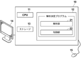
- FIG. 2 is a diagram showing a schematic configuration of an image analysis WS (image analysis device) 10 according to the first embodiment of the technology of the present disclosure, which is realized by installing an analysis function determination program in a computer.
- the image analysis WS 10 includes a CPU (Central Processing Unit) 11, a memory 12, and a storage 13 as a standard workstation configuration. Further, a display 14 such as a high-definition liquid crystal display and an input unit 15 such as a keyboard and a mouse are connected to the image analysis WS 10.
- a CPU Central Processing Unit
- the storage 13 comprises a storage device such as a hard disk or SSD (Solid State Drive).
- the storage 13 stores various information including medical images acquired via the network 6 and information necessary for processing.
- the memory 12 also stores an analysis function determination program.
- the analysis function determination program analyzes the input image data by an analysis function set in advance, and performs the analysis set in advance when an activation request is received from the outside. Based on an analysis result by the function and a preset condition, an analysis function to be activated is determined from a plurality of analysis functions, and a control process for controlling to activate the determined analysis function is defined.
- the computer functions as the analysis unit 21 and the control unit 22 by the CPU 11 executing these processes according to the program.
- the CPU 11 executes the function of each unit by the analysis function determining program.
- a programmable logic device which is a processor whose circuit configuration can be changed after manufacturing an FPGA (Field Programmable Gate Array) or the like, can be used.
- the processing of each unit may be executed by a dedicated electric circuit or the like which is a processor having a circuit configuration specifically designed to execute a specific processing such as an ASIC (Application Specific Integrated Circuit).
- One processing unit may be configured by one of these various processors, or may be a combination of two or more processors of the same type or different types (for example, a plurality of FPGAs or a combination of CPU and FPGA). It may be configured. Further, the plurality of processing units may be configured by one processor. As an example of configuring a plurality of processing units by one processor, firstly, one processor is configured by a combination of one or more CPUs and software, as represented by a computer such as a client or a server. There is a form in which the processor functions as a plurality of processing units.
- a processor that realizes the functions of the entire system including a plurality of processing units by one IC (Integrated Circuit) chip, as represented by a system on chip (SoC).
- SoC system on chip
- the various processing units are configured by using one or more of the above various processors as a hardware structure.
- the hardware-like structure of these various processors is, more specifically, an electrical circuit that combines circuit elements such as semiconductor elements.
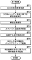
- FIG. 3 is a flowchart showing the processing performed in the first embodiment.
- the image reading WS3 transmits a medical image reading request to the image server 4, and the medical image data in DICOM format is received from the image server 4.
- the image interpretation WS3 transfers the received medical image data to the image analysis WS10.
- the image analysis WS10 receives the medical image data from the image interpretation WS3 (step ST1).
- the analysis unit 21 of the image analysis WS 10 performs analysis by a preset analysis function based on the image header information of the DICOM format medical image data (step ST2), and saves the analysis result in the storage 13 (step ST3). ..
- the medical image when the medical image is a cardiac CT image, it can be automatically determined that the received medical image is a cardiac CT image based on information such as the type of modality 2 used for imaging, a series description, and the number of slices. is there.
- a cardiac system analysis function such as a coronary artery analysis, a cardiac function analysis, and a calcification score is automatically executed, and image data of an image showing each analysis result is stored in the storage 13.
- analysis values calculated by each analysis function (stenosis rate and plaque amount for coronary artery analysis, EF (left ventricular ejection fraction: Ejection Fraction) and stroke volume, calcification for cardiac function analysis) If it is a score, the score value data is stored in the storage 13.
- FIG. 4 An example of image display at this time is shown in FIG. 4 as an example. As shown in FIG. 4, the entire screen 30 is roughly divided into two types of image display areas, a left side image display area 40 and a right side image display area 50.
- the left image display area 40 includes an image display area 41 and an analysis function button display frame 42.
- analysis function button display frame 42 analysis function buttons for executing an executable analysis function for the medical image displayed in the image display area 41 are displayed.
- a heart CT image is displayed in the image display area 41, and three types of analysis functions (coronary artery analysis, heart function analysis, and An example in which three analysis function buttons (a coronary artery analysis button 43, a cardiac function analysis 44, and a calcification score button 45) for executing a calcification score are displayed.
- the right image display area 50 includes an image display area 51 and an analysis function button display frame 52.
- analysis function button display frame 52 analysis function buttons for executing an executable analysis function on the medical image displayed in the image display area 51 are displayed.
- one analysis function button 53 is displayed in the analysis function button display frame 52.
- the image interpretation WS3 After performing the image display, the image interpretation WS3 sends a standby activation request for the analysis function to the image analysis WS10.
- the control unit 22 of the image analysis WS10 Upon receiving the standby activation request from the image interpretation WS3 (step ST4), the control unit 22 of the image analysis WS10 becomes an activation target from among the plurality of analysis functions based on the analysis result in step ST2 and the preset condition.
- the analysis function is determined (step ST5), and the determined analysis function is activated in the background (step ST6).
- the background activation means a state in which the software controlling the analysis function is activated in the image analysis WS (image analysis device) 10 and the screen of the analysis function is not displayed on the image interpretation WS 3.
- the preset condition for determining the analysis function to be activated is that the user (radiologist) really needs the medical image at the time of activation of the past image analysis WS10. It means a condition set based on learning data based on the information of the analysis function. For example, it is assumed that a coronary artery analysis, a cardiac function analysis, and a calcification score are performed when a cardiac CT examination is performed, but an abdominal examination may also be required and a fat analysis may be performed. In such a case, the combination data of the image header information and the actually required analysis function is accumulated, and learning is performed using this combination data to determine the analysis function required for the image header information. It can be performed with high precision.
- step ST6 for example, when the medical image is a cardiac CT image, the stenosis rate is low, and the EF is low, it is assumed that the details of these analysis states are observed, and therefore, the coronary artery analysis and the cardiac function analysis are backed up. Start on the ground.
- the display color of the analysis function button corresponding to the standby-started analysis function is displayed on the display of the image interpretation WS3 in a different color according to the standby start state.
- the analysis function button before standby activation is displayed in white
- the analysis function button during standby activation is displayed in gray (hatched in the figure)
- the analysis function button that has been activated in standby is displayed in black.
- a heart CT image is displayed in the image display area 41 of the left image display area 40, and three types of analysis functions (coronary artery analysis, heart function analysis) that can be executed on the heart CT image are displayed in the analysis function button display frame 42. , And calcification score), three analysis function buttons (coronary artery analysis button 43, heart function analysis 44, and calcification score button 45) for executing the coronary artery analysis and heart function analysis are displayed.
- the coronary artery analysis button 43 corresponding to the standby activated coronary artery analysis is displayed in black in accordance with the standby activation state
- the cardiac function analysis button 44 corresponding to the cardiac function analysis during standby activation is displayed. It is displayed in gray.
- the analysis function buttons in the right image display area 50 are also displayed in a display color that matches the standby activation state.
- control unit 22 may cause the analysis function that has been started in the background to perform the analysis process of the image data in the background.
- a standby activated analysis function button for example, the coronary artery analysis button 43 in FIG. 5
- a main activation request for the selected analysis function is transmitted from the image interpretation WS3 to the image analysis WS10.
- the identification information of the analysis function to be activated is attached to the data indicating the main activation request.
- the control unit 22 of the image analysis WS 10 Upon receiving the main activation request from the image interpretation WS 3, the control unit 22 of the image analysis WS 10 performs the main activation of the analysis function requested to perform the main activation based on the identification information in the data indicating the main activation request (step ST7).
- the main activation means a state in which the software controlling the analysis function is activated in the image analysis WS (image analysis apparatus) 10 and the image display of the corresponding analysis function is possible on the image interpretation WS 3. Then, the analysis result of the activated analysis function is transmitted to the image interpretation WS 3.
- the control unit 22 permanently activates the coronary artery analysis from the analysis functions that have been activated by standby, and transmits the result of the coronary artery analysis to the interpretation WS3. To do.
- the image interpretation WS 3 displays the result of the coronary artery analysis in the image display area 41 of the left image display area 40, as shown in FIG. 6.
- control unit 22 does not newly perform the analysis processing and saves the analysis result data of the analysis function that has been activated when the analysis result is already acquired in step ST2 and the data of the analysis result is saved in the storage 13.
- the analyzed result may be transmitted to the image interpretation WS3.
- the input image data is analyzed by a preset analysis function, and when a startup request is received from the outside, the analysis result by the preset analysis function and the preset Since only the necessary analysis function is activated from the plurality of analysis functions based on the set conditions, it is possible to reduce the activation load and the activation time of the image analysis WS 10.
- the image analysis apparatus of the present disclosure is not limited to the above embodiment, and various modifications and changes are made from the configuration of the above embodiment. Those provided with are also included in the technical scope of the present disclosure. Furthermore, the technique of the present disclosure extends to a storage medium that stores the program non-temporarily, in addition to the program.
Landscapes
- Engineering & Computer Science (AREA)
- Health & Medical Sciences (AREA)
- Software Systems (AREA)
- Theoretical Computer Science (AREA)
- Medical Informatics (AREA)
- Public Health (AREA)
- Physics & Mathematics (AREA)
- General Health & Medical Sciences (AREA)
- General Physics & Mathematics (AREA)
- Primary Health Care (AREA)
- Epidemiology (AREA)
- Radiology & Medical Imaging (AREA)
- General Engineering & Computer Science (AREA)
- Nuclear Medicine, Radiotherapy & Molecular Imaging (AREA)
- Biomedical Technology (AREA)
- Life Sciences & Earth Sciences (AREA)
- Computer Vision & Pattern Recognition (AREA)
- Data Mining & Analysis (AREA)
- Pathology (AREA)
- Artificial Intelligence (AREA)
- Mathematical Physics (AREA)
- Computing Systems (AREA)
- Evolutionary Computation (AREA)
- Computer Security & Cryptography (AREA)
- Biophysics (AREA)
- Databases & Information Systems (AREA)
- Heart & Thoracic Surgery (AREA)
- Molecular Biology (AREA)
- Surgery (AREA)
- Animal Behavior & Ethology (AREA)
- Veterinary Medicine (AREA)
- Apparatus For Radiation Diagnosis (AREA)
- Measuring And Recording Apparatus For Diagnosis (AREA)
- Medical Treatment And Welfare Office Work (AREA)
Abstract
起動時負荷の低減及び起動時間の短縮が可能な画像解析装置、解析機能決定方法、及び解析機能決定プログラムを提供する。 入力された画像データに対して予め設定された解析機能による解析を行う解析部と、外部から起動要求を受けた場合に、予め設定された解析機能による解析結果及び予め設定された条件に基づいて、複数の解析機能の中から起動対象となる解析機能を決定し、決定した解析機能を起動する制御を行う制御部とを備える。
Description
本開示は、画像解析装置、解析機能決定方法、及び解析機能決定プログラムに関する。
近年、X線撮影装置の他、CT(Computed Tomography)装置、超音波(US)診断装置、MRI(Magnetic Resonance Imaging)装置、PET(Positron Emission Tomography)装置、及びSPECT(Single-Photon Emission Computed Tomography)装置等の医療機器の進歩によって、より質の高い高解像度の3次元の医用画像を用いての画像診断が可能となってきている。特に、3次元の医用画像を用いた画像診断により、病変の領域を精度よく特定することができるため、特定した結果に基づいて適切な治療が行われるようになってきている。また、上記3次元の医用画像に対して、様々な解析アプリケーションによる解析を行うことにより、医用画像に含まれる病変等の領域、位置及び体積等を抽出し、これらを解析結果として取得することも行われている。このように、解析処理により生成される解析結果は、患者名、性別、年齢及び医用画像を取得したモダリティ等の検査情報と対応づけられて、データベースに保存されて、診断に供される。
一方、近年の画像診断システムは、医用画像を読影するための読影端末と、医用画像に対して詳細解析を行う画像解析装置とに大別できる。多くの場合は、読影医及び医師等のユーザが読影端末により疾患の有無を確認し、見つかった疾患に対して画像解析装置により詳細な解析を行うことにより、より正確な診断のための情報を収集する。なお、画像解析装置が読影端末と同様の読影機能を備えている場合には、画像解析装置を単独で運用することも可能である。このような画像解析装置として、例えば特開2009-268589号公報、特開2015-159861号公報、特開2007-144151号公報の画像解析装置が提案されている。
画像解析装置を読影端末のような他の装置から起動しようとする場合、他の装置上で実装されたユーザーインターフェースを起点として、画像解析装置が起動する。これにより、ワークフローが途絶えることなく画像解析装置を起動できるため、読影医は効率的に読影を行うことができる。
一方、1つの検査で行う解析機能は増加傾向にある。例えば、頭部CTを撮影した場合は、脳血管抽出、歯科解析、パフュージョン等の解析を行うことができる。また、心臓CTを撮影した場合は、冠動脈解析、心機能解析、石灰化スコア、アブレーション解析等を行うことができる。近年、幅広い解析方法が生み出されていること、また術前シミュレーション機能が普及してきていることから、今後画像解析装置の解析機能が増加する可能性は高い。このような状況において、画像解析装置を起動する場合、多数の解析機能を起動することになるため、起動時の負荷が大きくなるとともに、起動時間が長くなるおそれがある。
特開2009-268589号公報、特開2015-159861号公報、特開2007-144151号公報では、検査情報または画像付帯情報に基づいて検査に関係する解析機能を決定し、決定した解析機能を起動することが開示されている。例えば、心臓CTを撮影した場合は、冠動脈解析、心機能解析、石灰化スコア、アブレーション解析等、心臓検査に関係する解析機能のみが起動されることになる。
しかしながら、読影医は、検査に関係する全ての解析機能を使用するわけではなく、患者の病状に応じて必要な解析機能は限られるため、使用しない解析機能の起動により、不必要な起動時負荷及び起動時間を生じてしまっている。
本開示は、上記事情に鑑みなされたものであり、起動時負荷の低減及び起動時間の短縮が可能な画像解析装置、解析機能決定方法、及び解析機能決定プログラムを提供することを目的とするものである。
本開示による画像解析装置は、入力された画像データに対して予め設定された解析機能による解析を行う解析部と、外部から起動要求を受けた場合に、予め設定された解析機能による解析結果及び予め設定された条件に基づいて、複数の解析機能の中から起動対象となる解析機能を決定し、決定した解析機能を起動する制御を行う制御部とを備える。
本開示による画像解析装置において、制御部は、画像データ及び画像データのヘッダー情報の少なくとも一方に基づいて、予め設定された解析機能を設定してもよい。
また、制御部は、起動対象として決定した解析機能をバックグラウンドで起動し、さらに外部から本起動要求を受けた場合にバックグラウンド起動済みの解析機能を本起動してもよい。
また、制御部は、バックグラウンド起動済みの解析機能に対し、画像データの解析処理をバックグラウンドで行わせてもよい。
また、外部からの本起動要求は解析機能の識別情報を含み、制御部は、識別情報に基づいて本起動する解析機能を決定してもよい。
また、予め設定された解析機能による解析結果を保存する保存部を備え、制御部は、起動した解析機能の解析結果が保存部に保存されている場合、保存部に保存された解析結果を出力してもよい。
また、予め設定された条件は、学習により更新されてもよい。
本開示による解析機能決定方法は、入力された画像データに対して予め設定された解析機能による解析を行い、外部から起動要求を受けた場合に、予め設定された解析機能による解析結果及び予め設定された条件に基づいて、複数の解析機能の中から起動対象となる解析機能を決定し、決定した解析機能を起動する。
本開示による解析機能決定プログラムは、入力された画像データに対して予め設定された解析機能による解析を行う手順と、外部から起動要求を受けた場合に、予め設定された解析機能による解析結果及び予め設定された条件に基づいて、複数の解析機能の中から起動対象となる解析機能を決定し、決定した解析機能を起動する手順とをコンピュータに実行させる。
本開示によれば、起動時負荷の低減及び起動時間の短縮が可能な画像解析装置、解析機能決定方法、及び解析機能決定プログラムを提供することができる。
以下、図面を参照して本開示の実施形態について説明する。図1は本開示の一実施形態による画像解析装置を適用した画像診断システムの概略構成を示す図である。図1に示す画像診断システム1は、公知のオーダリングシステムを用いた診療科の医師からの検査オーダーに基づいて、被写体の検査対象部位の撮影、撮影により取得された医用画像の保管、及び読影医による医用画像の読影等を行うためのシステムである。
図1に示すように、画像診断システム1は、複数のモダリティ(撮影装置)2、読影端末である複数の読影ワークステーション(WS)3、画像サーバ4、画像データベース5、及び本実施形態による画像解析装置である画像解析ワークステーション(WS)10が、ネットワーク6を介して互いに通信可能な状態で接続されて構成されている。
各機器は、画像診断システム1の構成要素として機能させるためのアプリケーションプログラムがインストールされたコンピュータである。アプリケーションプログラムは、DVD(Digital Versatile Disc)あるいはCD-ROM(Compact Disc Read Only Memory)等の記録媒体に記録されて配布され、その記録媒体からコンピュータにインストールされる。または、ネットワークに接続されたサーバコンピュータの記憶装置、もしくはネットワークストレージに、外部からアクセス可能な状態で記憶され、要求に応じてコンピュータにダウンロードされ、インストールされる。
モダリティ2は、被写体の診断対象となる部位を撮影することにより、診断対象部位を表す医用画像を生成する装置である。具体的には、CT装置、MRI装置、及びPET装置等である。モダリティ2により生成された医用画像は、画像サーバ4に送信され、保存される。
読影WS3は、医用画像の読影医が、医用画像の読影に使用するコンピュータであり、処理装置、高精細ディスプレイ、並びにキーボード及びマウス等の入力装置により構成される。読影WS3では、画像サーバ4に対する医用画像の閲覧要求、画像サーバ4から受信した医用画像に対する各種画像処理、医用画像の表示、画像解析WS10に対する医用画像転送処理、画像解析WS10に対する画像解析依頼、及び画像解析結果の表示等の各処理が、各処理のためのソフトウェアプログラムを実行することにより行われる。
画像サーバ4は、汎用の比較的処理能力の高いコンピュータにデータベース管理システム(DataBase Management System: DBMS)の機能を提供するソフトウェアプログラムがインストールされたものである。また、画像サーバ4は画像データベース5が構成される大容量ストレージを備えている。このストレージは、画像サーバ4とデータバスによって接続された大容量のハードディスク装置であってもよいし、ネットワーク6に接続されているNAS(Network Attached Storage)及びSAN(Storage Area Network)に接続されたディスク装置であってもよい。また、画像サーバ4は、モダリティ2からの医用画像の登録要求を受け付けると、その医用画像をデータベース用のフォーマットに整えて画像データベース5に登録する。
画像データベース5には、モダリティ2において取得された医用画像の画像データと付帯情報とが、DICOM(Digital Imaging and COmmunications in Medicine)形式に基づいて登録される。付帯情報には、例えば、個々の医用画像を識別するための画像ID、被写体を識別するための患者ID(identification)、検査を識別するための検査ID、医用画像毎に割り振られるユニークなID(UID:unique identification)、その医用画像が生成された検査日、検査時刻、その医用画像を取得するための検査で使用されたモダリティの種類、患者氏名、年齢、性別等の患者情報、検査部位(撮影部位)、撮影情報(撮影プロトコル、撮影シーケンス、撮像手法、撮影条件、造影剤の使用等)、1回の検査で複数の医用画像を取得したときのシリーズ番号あるいは採取番号等の情報が含まれうる。
また、画像サーバ4は、読影WS3からの閲覧要求をネットワーク6経由で受信すると、画像データベース5に登録されている医用画像を検索し、抽出された医用画像を要求元の読影WS3に送信する。
ネットワーク6は、病院内の各種機器を接続する有線または無線のローカルエリアネットワークである。読影医用ワークステーション3が他の病院あるいは診療所に設置されている場合には、ネットワーク6は、各病院のローカルエリアネットワーク同士をインターネットまたは専用回線で接続した構成としてもよい。いずれの場合にも、ネットワーク6は光ネットワーク等の医用画像の高速転送が実現可能な構成にすることが好ましい。
以下、本実施形態による画像解析装置である画像解析WS10について詳細に説明する。画像解析WS10は、1台のコンピュータに、本実施形態の解析機能決定プログラムをインストールしたものである。コンピュータは、診断を行う医師又は読影医が直接操作するワークステーションまたはパーソナルコンピュータでもよいし、それらとネットワークを介して接続されたサーバコンピュータでもよい。解析機能決定プログラムは、DVDあるいはCD-ROM等の記録媒体に記録されて配布され、その記録媒体からコンピュータにインストールされる。または、ネットワークに接続されたサーバコンピュータの記憶装置、もしくはネットワークストレージに、外部からアクセス可能な状態で記憶され、要求に応じてコンピュータにダウンロードされ、インストールされる。
図2は、コンピュータに解析機能決定プログラムをインストールすることにより実現される、本開示の技術に係る第1の実施形態による画像解析WS(画像解析装置)10の概略構成を示す図である。図2に示すように、画像解析WS10は、標準的なワークステーションの構成として、CPU(Central Processing Unit)11、メモリ12、及びストレージ13を備えている。また、画像解析WS10には、高精細な液晶ディスプレイ等のディスプレイ14、並びにキーボード及びマウス等の入力部15が接続されている。
ストレージ13は、ハードディスクまたはSSD(Solid State Drive)等のストレージデバイスからなる。ストレージ13には、ネットワーク6を経由して取得した医用画像及び処理に必要な情報を含む各種情報が記憶されている。
また、メモリ12には、解析機能決定プログラムが記憶されている。解析機能決定プログラムは、CPU11に実行させる処理として、入力された画像データに対して予め設定された解析機能による解析を行う解析処理と、外部から起動要求を受けた場合に、予め設定された解析機能による解析結果及び予め設定された条件に基づいて、複数の解析機能の中から起動対象となる解析機能を決定し、決定した解析機能を起動する制御を行う制御処理とを規定する。CPU11がプログラムに従いこれらの処理を実行することで、コンピュータは、解析部21及び制御部22として機能する。
なお、本実施形態においては、CPU11が解析機能決定プログラムによって、各部の機能を実行するようにしたが、ソフトウェアを実行して各種の処理部として機能する汎用的なプロセッサとしては、CPU11の他、FPGA (Field Programmable Gate Array)等の製造後に回路構成を変更可能なプロセッサであるプログラマブルロジックデバイス(Programmable Logic Device:PLD)を用いることができる。また、ASIC(Application Specific Integrated Circuit)等の特定の処理を実行させるために専用に設計された回路構成を有するプロセッサである専用電気回路等により、各部の処理を実行するようにしてもよい。
1つの処理部は、これら各種のプロセッサのうちの1つで構成されてもよいし、同種または異種の2つ以上のプロセッサの組み合せ(例えば、複数のFPGA、またはCPUとFPGAの組み合わせ等)で構成されてもよい。また、複数の処理部を1つのプロセッサで構成してもよい。複数の処理部を1つのプロセッサで構成する例としては、第1に、クライアントやサーバ等のコンピュータに代表されるように、1つ以上のCPUとソフトウェアの組み合わせで1つのプロセッサを構成し、このプロセッサが複数の処理部として機能する形態がある。第2に、システムオンチップ(System On Chip:SoC)などに代表されるように、複数の処理部を含むシステム全体の機能を1つのIC(Integrated Circuit)チップで実現するプロセッサを使用する形態がある。このように、各種の処理部は、ハードウェア的な構造として、上記各種のプロセッサを1つ以上を用いて構成される。
さらに、これらの各種のプロセッサのハードウェア的な構造は、より具体的には、半導体素子等の回路素子を組み合わせた電気回路(circuitry)である。
次いで、本実施形態において行われる処理について説明する。図3は第1の実施形態において行われる処理を示すフローチャートである。
医用画像の読影医が、読影WS3において医用画像を閲覧しようとすると、読影WS3から画像サーバ4に対する医用画像の閲覧要求が送信され、画像サーバ4からDICOM形式の医用画像データを受信する。このとき、読影WS3は受信した医用画像データを画像解析WS10に転送する。画像解析WS10は、読影WS3から医用画像データを受信する(ステップST1)。
画像解析WS10の解析部21は、DICOM形式の医用画像データの画像ヘッダー情報に基づいて、予め設定された解析機能による解析を行い(ステップST2)、解析結果をストレージ13に保存する(ステップST3)。
例えば、医用画像が心臓CT画像である場合、撮影を行ったモダリティ2の種類、シリーズ説明、及びスライス枚数等の情報に基づいて、受信した医用画像が心臓CT画像であることが自動判別可能である。心臓CT画像の場合、冠動脈解析、心機能解析、及び石灰化スコアといった心臓系解析機能が自動実行されて、各々の解析結果を示す画像の画像データがストレージ13に保存される。また、各々の解析機能により算出された解析値(冠動脈解析であれば狭窄率及びプラーク量、心機能解析であればEF(左室駆出率:Ejection Fraction)及び一回拍出量、石灰化スコアであればスコア値)のデータがストレージ13に保存される。
読影WS3における医用画像の表示時において、読影WS3のディスプレイ上には、医用画像とともに、各種UI(User Interface)が表示される。このときの画像表示例を一例として図4に示す。図4に示すように、全体画面30内には、大きく分けて左側画像表示領域40及び右側画像表示領域50の2種類の画像表示領域がある。
左側画像表示領域40は、画像表示領域41及び解析機能ボタン表示枠42を備える。解析機能ボタン表示枠42内には、画像表示領域41に表示されている医用画像に対して実行可能な解析機能を実行させるための解析機能ボタンが表示される。ここでは、一例として、画像表示領域41に心臓CT画像が表示され、解析機能ボタン表示枠42内に、心臓CT画像に対して実行可能な3種類の解析機能(冠動脈解析、心機能解析、及び石灰化スコア)を実行させるための、3つの解析機能ボタン(冠動脈解析ボタン43、心機能解析44、及び石灰化スコアボタン45)が表示された例を示す。
同様に、右側画像表示領域50は、画像表示領域51及び解析機能ボタン表示枠52を備える。解析機能ボタン表示枠52内には、画像表示領域51に表示されている医用画像に対して実行可能な解析機能を実行させるための解析機能ボタンが表示される。ここでは、一例として、解析機能ボタン表示枠52内に、1つの解析機能ボタン53が表示された例を示す。
また、読影WS3は、上記画像表示を行った後、解析機能のスタンバイ起動要求を画像解析WS10に送信する。画像解析WS10の制御部22は、読影WS3からスタンバイ起動要求を受信する(ステップST4)と、ステップST2における解析結果及び予め設定された条件に基づいて、複数の解析機能の中から起動対象となる解析機能を決定し(ステップST5)、決定した解析機能をバックグラウンドで起動させる(ステップST6)。
ここでバックグラウンドの起動とは、画像解析WS(画像解析装置)10において解析機能を司るソフトウェアが起動し、かつ、読影WS3に該当の解析機能の画面表示を行っていない状態を意味する。また、ステップST5において、起動対象となる解析機能を決定するための、予め設定された条件とは、過去の画像解析WS10の起動時において、医用画像に対してユーザー(読影医)が本当に必要とした解析機能の情報に基づく学習データに基づいて設定された条件を意味する。例えば、心臓CT検査を行った場合、冠動脈解析、心機能解析、石灰化スコアが実行されることを想定しているが、腹部検査も必要とされて脂肪解析が実行される場合がある。このような場合に、画像ヘッダー情報と実際に必要とした解析機能の組み合わせデータを蓄積して、この組み合わせデータを用いて学習を行うことにより、画像ヘッダー情報に対して必要な解析機能の決定を高精度に行うことができる。
ステップST6において、例えば、医用画像が心臓CT画像であり、狭窄率が低く、EFが低い場合は、これらの解析状態の詳細を観察することが想定されるため、冠動脈解析及び心機能解析をバックグラウンドで起動しておく。
このとき、読影WS3のディスプレイ上には、図5に示すように、スタンバイ起動した解析機能に対応する解析機能ボタンの表示色が、スタンバイ起動状態に合わせて異なる色で表示される。ここでは、スタンバイ起動前の解析機能ボタンを白色表示、スタンバイ起動中の解析機能ボタンを灰色表示(図中ハッチング表示)、スタンバイ起動済みの解析機能ボタンを黒色表示とする。
例えば、左側画像表示領域40の画像表示領域41に心臓CT画像が表示され、解析機能ボタン表示枠42内に、心臓CT画像に対して実行可能な3種類の解析機能(冠動脈解析、心機能解析、及び石灰化スコア)を実行させるための、3つの解析機能ボタン(冠動脈解析ボタン43、心機能解析44、及び石灰化スコアボタン45)が表示されている場合において、冠動脈解析及び心機能解析が起動対象として決定された場合、スタンバイ起動の状態に合わせて、スタンバイ起動済みの冠動脈解析に対応した冠動脈解析ボタン43が黒色表示され、スタンバイ起動中の心機能解析に対応した心機能解析ボタン44が灰色表示される。同様に、右側画像表示領域50の解析機能ボタンについても、スタンバイ起動状態に合わせた表示色で表示される。
ここで、制御部22は、バックグラウンド起動済みの解析機能に対し、画像データの解析処理をバックグラウンドで行わせてもよい。
読影WS3においてスタンバイ起動済みの解析機能ボタン(例えば、図5における冠動脈解析ボタン43)が選択入力されると、選択された解析機能の本起動要求が、読影WS3から画像解析WS10に送信される。このとき、本起動要求を示すデータの中に、起動する解析機能の識別情報が付帯される。
画像解析WS10の制御部22は、読影WS3から本起動要求を受信すると、本起動要求を示すデータ中の識別情報に基づいて、本起動要求された解析機能の本起動を行う(ステップST7)。ここで本起動とは、画像解析WS(画像解析装置)10において解析機能を司るソフトウェアが起動し、かつ、読影WS3に該当の解析機能の画面表示が可能な状態を意味する。そして、本起動した解析機能の解析結果を読影WS3に送信する。
例えば、図5に示す画面状態において冠動脈解析ボタン43が選択入力されると、制御部22は、スタンバイ起動済みの解析機能の中から冠動脈解析を本起動し、冠動脈解析の結果を読影WS3に送信する。読影WS3は、冠動脈解析の結果を受信すると、図6に示すように、左側画像表示領域40の画像表示領域41に、冠動脈解析の結果を表示する。
このとき、制御部22は、本起動した解析機能の解析結果がステップST2において取得済みであり、解析結果のデータがストレージ13に保存されている場合には、新たに解析処理を行わず、保存されている解析結果を読影WS3に送信してもよい。
本実施形態の画像診断システムにおいては、入力された画像データに対して予め設定された解析機能による解析を行い、外部から起動要求を受けた場合に、予め設定された解析機能による解析結果及び予め設定された条件に基づいて、複数の解析機能の中から必要な解析機能のみを起動するようにしているため、画像解析WS10の起動時負荷の低減及び起動時間の短縮を図ることができる。
以上、本開示の技術をその好適な実施形態に基づいて説明したが、本開示の画像解析装置は、上記実施形態にのみ限定されるものではなく、上記実施形態の構成から種々の修正および変更を施したものも、本開示の技術範囲に含まれる。さらに、本開示の技術は、プログラムに加えて、プログラムを非一時的に記憶する記憶媒体にもおよぶ。
2018年11月20日に出願された日本出願特願2018-217752の開示はその全体が参照により本明細書に取り込まれる。本明細書に記載された全ての文献、特許出願、及び技術規格は、個々の文献、特許出願、及び技術規格が参照により取り込まれることが具体的かつ個々に記された場合と同程度に、本明細書中に参照により取り込まれる。
Claims (9)
- 入力された画像データに対して予め設定された解析機能による解析を行う解析部と、
外部から起動要求を受けた場合に、前記予め設定された解析機能による解析結果及び予め設定された条件に基づいて、複数の解析機能の中から起動対象となる解析機能を決定し、決定した解析機能を起動する制御を行う制御部とを備える画像解析装置。 - 前記制御部は、前記画像データ及び前記画像データのヘッダー情報の少なくとも一方に基づいて、前記予め設定された解析機能を設定する
請求項1に記載の画像解析装置。 - 前記制御部は、起動対象として決定した解析機能をバックグラウンドで起動し、さらに外部から本起動要求を受けた場合にバックグラウンド起動済みの解析機能を本起動する
請求項1または2に記載の画像解析装置。 - 前記制御部は、バックグラウンド起動済みの解析機能に対し、前記画像データの解析処理をバックグラウンドで行わせる
請求項3に記載の画像解析装置。 - 外部からの本起動要求は解析機能の識別情報を含み、
前記制御部は、前記識別情報に基づいて本起動する解析機能を決定する
請求項3または4に記載の画像解析装置。 - 前記予め設定された解析機能による解析結果を保存する保存部を備え、
前記制御部は、起動した解析機能の解析結果が前記保存部に保存されている場合、前記保存部に保存された解析結果を出力する
請求項1から5のいずれか1項に記載の画像解析装置。 - 前記予め設定された条件は、学習により更新される
請求項1から6のいずれか1項に記載の画像解析装置。 - 入力された画像データに対して予め設定された解析機能による解析を行い、
外部から起動要求を受けた場合に、前記予め設定された解析機能による解析結果及び予め設定された条件に基づいて、複数の解析機能の中から起動対象となる解析機能を決定し、決定した解析機能を起動する解析機能決定方法。 - 入力された画像データに対して予め設定された解析機能による解析を行う手順と、
外部から起動要求を受けた場合に、前記予め設定された解析機能による解析結果及び予め設定された条件に基づいて、複数の解析機能の中から起動対象となる解析機能を決定し、決定した解析機能を起動する手順とをコンピュータに実行させる解析機能決定プログラム。
Priority Applications (2)
| Application Number | Priority Date | Filing Date | Title |
|---|---|---|---|
| JP2020557567A JP7209738B2 (ja) | 2018-11-20 | 2019-11-19 | 画像解析装置、解析機能決定方法、及び解析機能決定プログラム |
| US17/322,919 US12315123B2 (en) | 2018-11-20 | 2021-05-18 | Image analysis device, analysis function decision method, and analysis function decision program |
Applications Claiming Priority (2)
| Application Number | Priority Date | Filing Date | Title |
|---|---|---|---|
| JP2018217752 | 2018-11-20 | ||
| JP2018-217752 | 2018-11-20 |
Related Child Applications (1)
| Application Number | Title | Priority Date | Filing Date |
|---|---|---|---|
| US17/322,919 Continuation US12315123B2 (en) | 2018-11-20 | 2021-05-18 | Image analysis device, analysis function decision method, and analysis function decision program |
Publications (1)
| Publication Number | Publication Date |
|---|---|
| WO2020105645A1 true WO2020105645A1 (ja) | 2020-05-28 |
Family
ID=70773797
Family Applications (1)
| Application Number | Title | Priority Date | Filing Date |
|---|---|---|---|
| PCT/JP2019/045318 Ceased WO2020105645A1 (ja) | 2018-11-20 | 2019-11-19 | 画像解析装置、解析機能決定方法、及び解析機能決定プログラム |
Country Status (3)
| Country | Link |
|---|---|
| US (1) | US12315123B2 (ja) |
| JP (1) | JP7209738B2 (ja) |
| WO (1) | WO2020105645A1 (ja) |
Cited By (1)
| Publication number | Priority date | Publication date | Assignee | Title |
|---|---|---|---|---|
| JP2023049302A (ja) * | 2021-09-29 | 2023-04-10 | コニカミノルタ株式会社 | 動態画像解析装置及びプログラム |
Families Citing this family (1)
| Publication number | Priority date | Publication date | Assignee | Title |
|---|---|---|---|---|
| CN115527097A (zh) * | 2022-11-01 | 2022-12-27 | 厦门大学 | 一种基于消融分析的cnn解释图对象相关性分析方法 |
Citations (5)
| Publication number | Priority date | Publication date | Assignee | Title |
|---|---|---|---|---|
| JP2008210383A (ja) * | 2007-02-19 | 2008-09-11 | Toshiba Corp | ジョブテンプレート自動生成装置、及びジョブテンプレート自動生成方法 |
| JP2011050608A (ja) * | 2009-09-02 | 2011-03-17 | Toshiba Corp | 超音波診断装置および画像解析装置 |
| JP2013081713A (ja) * | 2011-10-12 | 2013-05-09 | Toshiba Corp | 医用画像処理装置 |
| JP2017080398A (ja) * | 2015-10-30 | 2017-05-18 | キヤノンマーケティングジャパン株式会社 | 医用画像処理装置、その制御方法、及びプログラム |
| WO2018079246A1 (ja) * | 2016-10-25 | 2018-05-03 | 富士フイルム株式会社 | 画像解析装置、方法およびプログラム |
Family Cites Families (6)
| Publication number | Priority date | Publication date | Assignee | Title |
|---|---|---|---|---|
| US20070063998A1 (en) * | 2005-09-21 | 2007-03-22 | General Electric Company | Self-learning adaptive PACS workstation system and method |
| JP5268242B2 (ja) | 2005-11-01 | 2013-08-21 | 株式会社東芝 | 医用画像表示システム及び医用画像表示プログラム |
| US7751604B2 (en) * | 2006-11-30 | 2010-07-06 | Fujifilm Corporation | Medical intelligent server architecture |
| JP5161646B2 (ja) | 2008-05-01 | 2013-03-13 | 株式会社東芝 | 医用画像診断装置およびその制御プログラム |
| JP6309306B2 (ja) | 2014-02-26 | 2018-04-11 | キヤノンメディカルシステムズ株式会社 | 医用情報表示装置 |
| WO2017073703A1 (ja) | 2015-10-30 | 2017-05-04 | キヤノン株式会社 | 医用画像処理装置、その制御方法、及びプログラム |
-
2019
- 2019-11-19 JP JP2020557567A patent/JP7209738B2/ja active Active
- 2019-11-19 WO PCT/JP2019/045318 patent/WO2020105645A1/ja not_active Ceased
-
2021
- 2021-05-18 US US17/322,919 patent/US12315123B2/en active Active
Patent Citations (5)
| Publication number | Priority date | Publication date | Assignee | Title |
|---|---|---|---|---|
| JP2008210383A (ja) * | 2007-02-19 | 2008-09-11 | Toshiba Corp | ジョブテンプレート自動生成装置、及びジョブテンプレート自動生成方法 |
| JP2011050608A (ja) * | 2009-09-02 | 2011-03-17 | Toshiba Corp | 超音波診断装置および画像解析装置 |
| JP2013081713A (ja) * | 2011-10-12 | 2013-05-09 | Toshiba Corp | 医用画像処理装置 |
| JP2017080398A (ja) * | 2015-10-30 | 2017-05-18 | キヤノンマーケティングジャパン株式会社 | 医用画像処理装置、その制御方法、及びプログラム |
| WO2018079246A1 (ja) * | 2016-10-25 | 2018-05-03 | 富士フイルム株式会社 | 画像解析装置、方法およびプログラム |
Cited By (2)
| Publication number | Priority date | Publication date | Assignee | Title |
|---|---|---|---|---|
| JP2023049302A (ja) * | 2021-09-29 | 2023-04-10 | コニカミノルタ株式会社 | 動態画像解析装置及びプログラム |
| JP7782189B2 (ja) | 2021-09-29 | 2025-12-09 | コニカミノルタ株式会社 | 動態画像解析装置及びプログラム |
Also Published As
| Publication number | Publication date |
|---|---|
| US20210272254A1 (en) | 2021-09-02 |
| JP7209738B2 (ja) | 2023-01-20 |
| US12315123B2 (en) | 2025-05-27 |
| JPWO2020105645A1 (ja) | 2021-10-14 |
Similar Documents
| Publication | Publication Date | Title |
|---|---|---|
| JP6906462B2 (ja) | 医用画像表示装置、方法およびプログラム | |
| WO2022215530A1 (ja) | 医用画像装置、医用画像方法、及び医用画像プログラム | |
| JP2020054579A (ja) | 疾患領域抽出装置、方法及びプログラム | |
| JP7524334B2 (ja) | 画像表示装置、方法およびプログラム | |
| JP7756107B2 (ja) | 画像表示装置、方法およびプログラム | |
| WO2021107098A1 (ja) | 文書作成支援装置、文書作成支援方法及び文書作成支援プログラム | |
| US11574402B2 (en) | Inspection information display device, method, and program | |
| JP7212147B2 (ja) | 医療文書作成支援装置、方法およびプログラム | |
| JP7844358B2 (ja) | 情報処理装置、方法およびプログラム | |
| JP7371220B2 (ja) | 情報処理装置、情報処理方法及び情報処理プログラム | |
| US12315123B2 (en) | Image analysis device, analysis function decision method, and analysis function decision program | |
| JP7462424B2 (ja) | 医用情報処理装置、学習用データ生成プログラムおよび学習用データ生成方法 | |
| US11328414B2 (en) | Priority judgement device, method, and program | |
| WO2021193548A1 (ja) | 文書作成支援装置、方法およびプログラム | |
| JP7109345B2 (ja) | 優先度判定装置、方法およびプログラム | |
| WO2020066132A1 (ja) | 医用画像診断支援装置、方法及びプログラム | |
| JP2019213784A (ja) | 治療方針決定支援装置、治療方針決定支援装置の作動方法、および治療方針決定支援プログラム | |
| JP6968195B2 (ja) | 検査情報表示装置、方法およびプログラム | |
| JP2025178348A (ja) | 医用画像表示装置、方法およびプログラム | |
| US12423809B2 (en) | Medical image processing apparatus, method, and program for detecting abnormal region by setting threshold | |
| JP2021175454A (ja) | 医用画像処理装置、方法およびプログラム | |
| JP7480305B2 (ja) | 診断支援装置とその作動方法及び作動プログラム、並びに診断支援システム | |
| JP7376715B2 (ja) | 経過予測装置、経過予測装置の作動方法および経過予測プログラム | |
| WO2020105416A1 (ja) | 医療情報表示装置、方法およびプログラム、並びに医療情報を表示するためのグラフィックユーザインターフェース | |
| JPWO2020105415A1 (ja) | 医療情報表示装置、方法およびプログラム、並びに医療情報を表示するためのグラフィックユーザインターフェース |
Legal Events
| Date | Code | Title | Description |
|---|---|---|---|
| 121 | Ep: the epo has been informed by wipo that ep was designated in this application |
Ref document number: 19887175 Country of ref document: EP Kind code of ref document: A1 |
|
| ENP | Entry into the national phase |
Ref document number: 2020557567 Country of ref document: JP Kind code of ref document: A |
|
| NENP | Non-entry into the national phase |
Ref country code: DE |
|
| 122 | Ep: pct application non-entry in european phase |
Ref document number: 19887175 Country of ref document: EP Kind code of ref document: A1 |