WO2020105534A1 - 逐次近似計算方法、逐次近似計算装置およびプログラム - Google Patents
逐次近似計算方法、逐次近似計算装置およびプログラムInfo
- Publication number
- WO2020105534A1 WO2020105534A1 PCT/JP2019/044657 JP2019044657W WO2020105534A1 WO 2020105534 A1 WO2020105534 A1 WO 2020105534A1 JP 2019044657 W JP2019044657 W JP 2019044657W WO 2020105534 A1 WO2020105534 A1 WO 2020105534A1
- Authority
- WO
- WIPO (PCT)
- Prior art keywords
- phase
- data
- interference fringe
- successive approximation
- calculation
- Prior art date
- Legal status (The legal status is an assumption and is not a legal conclusion. Google has not performed a legal analysis and makes no representation as to the accuracy of the status listed.)
- Ceased
Links
Images



Classifications
-
- G—PHYSICS
- G06—COMPUTING OR CALCULATING; COUNTING
- G06F—ELECTRIC DIGITAL DATA PROCESSING
- G06F17/00—Digital computing or data processing equipment or methods, specially adapted for specific functions
- G06F17/10—Complex mathematical operations
- G06F17/17—Function evaluation by approximation methods, e.g. inter- or extrapolation, smoothing, least mean square method
-
- G—PHYSICS
- G06—COMPUTING OR CALCULATING; COUNTING
- G06T—IMAGE DATA PROCESSING OR GENERATION, IN GENERAL
- G06T12/00—Tomographic reconstruction from projections
- G06T12/20—Inverse problem, i.e. transformations from projection space into object space
-
- G—PHYSICS
- G03—PHOTOGRAPHY; CINEMATOGRAPHY; ANALOGOUS TECHNIQUES USING WAVES OTHER THAN OPTICAL WAVES; ELECTROGRAPHY; HOLOGRAPHY
- G03H—HOLOGRAPHIC PROCESSES OR APPARATUS
- G03H1/00—Holographic processes or apparatus using light, infrared or ultraviolet waves for obtaining holograms or for obtaining an image from them; Details peculiar thereto
- G03H1/04—Processes or apparatus for producing holograms
- G03H1/08—Synthesising holograms, i.e. holograms synthesized from objects or objects from holograms
- G03H1/0808—Methods of numerical synthesis, e.g. coherent ray tracing [CRT], diffraction specific
-
- G—PHYSICS
- G06—COMPUTING OR CALCULATING; COUNTING
- G06N—COMPUTING ARRANGEMENTS BASED ON SPECIFIC COMPUTATIONAL MODELS
- G06N3/00—Computing arrangements based on biological models
- G06N3/02—Neural networks
- G06N3/04—Architecture, e.g. interconnection topology
- G06N3/045—Combinations of networks
-
- G—PHYSICS
- G06—COMPUTING OR CALCULATING; COUNTING
- G06N—COMPUTING ARRANGEMENTS BASED ON SPECIFIC COMPUTATIONAL MODELS
- G06N3/00—Computing arrangements based on biological models
- G06N3/02—Neural networks
- G06N3/04—Architecture, e.g. interconnection topology
- G06N3/0464—Convolutional networks [CNN, ConvNet]
-
- G—PHYSICS
- G06—COMPUTING OR CALCULATING; COUNTING
- G06N—COMPUTING ARRANGEMENTS BASED ON SPECIFIC COMPUTATIONAL MODELS
- G06N3/00—Computing arrangements based on biological models
- G06N3/02—Neural networks
- G06N3/08—Learning methods
- G06N3/09—Supervised learning
-
- G—PHYSICS
- G06—COMPUTING OR CALCULATING; COUNTING
- G06T—IMAGE DATA PROCESSING OR GENERATION, IN GENERAL
- G06T12/00—Tomographic reconstruction from projections
-
- G—PHYSICS
- G03—PHOTOGRAPHY; CINEMATOGRAPHY; ANALOGOUS TECHNIQUES USING WAVES OTHER THAN OPTICAL WAVES; ELECTROGRAPHY; HOLOGRAPHY
- G03H—HOLOGRAPHIC PROCESSES OR APPARATUS
- G03H1/00—Holographic processes or apparatus using light, infrared or ultraviolet waves for obtaining holograms or for obtaining an image from them; Details peculiar thereto
- G03H1/04—Processes or apparatus for producing holograms
- G03H1/0443—Digital holography, i.e. recording holograms with digital recording means
-
- G—PHYSICS
- G03—PHOTOGRAPHY; CINEMATOGRAPHY; ANALOGOUS TECHNIQUES USING WAVES OTHER THAN OPTICAL WAVES; ELECTROGRAPHY; HOLOGRAPHY
- G03H—HOLOGRAPHIC PROCESSES OR APPARATUS
- G03H1/00—Holographic processes or apparatus using light, infrared or ultraviolet waves for obtaining holograms or for obtaining an image from them; Details peculiar thereto
- G03H1/04—Processes or apparatus for producing holograms
- G03H1/0443—Digital holography, i.e. recording holograms with digital recording means
- G03H2001/0447—In-line recording arrangement
-
- G—PHYSICS
- G03—PHOTOGRAPHY; CINEMATOGRAPHY; ANALOGOUS TECHNIQUES USING WAVES OTHER THAN OPTICAL WAVES; ELECTROGRAPHY; HOLOGRAPHY
- G03H—HOLOGRAPHIC PROCESSES OR APPARATUS
- G03H1/00—Holographic processes or apparatus using light, infrared or ultraviolet waves for obtaining holograms or for obtaining an image from them; Details peculiar thereto
- G03H1/04—Processes or apparatus for producing holograms
- G03H1/08—Synthesising holograms, i.e. holograms synthesized from objects or objects from holograms
- G03H1/0808—Methods of numerical synthesis, e.g. coherent ray tracing [CRT], diffraction specific
- G03H2001/0816—Iterative algorithms
-
- G—PHYSICS
- G03—PHOTOGRAPHY; CINEMATOGRAPHY; ANALOGOUS TECHNIQUES USING WAVES OTHER THAN OPTICAL WAVES; ELECTROGRAPHY; HOLOGRAPHY
- G03H—HOLOGRAPHIC PROCESSES OR APPARATUS
- G03H1/00—Holographic processes or apparatus using light, infrared or ultraviolet waves for obtaining holograms or for obtaining an image from them; Details peculiar thereto
- G03H1/26—Processes or apparatus specially adapted to produce multiple sub- holograms or to obtain images from them, e.g. multicolour technique
- G03H1/2645—Multiplexing processes, e.g. aperture, shift, or wavefront multiplexing
- G03H2001/266—Wavelength multiplexing
-
- G—PHYSICS
- G03—PHOTOGRAPHY; CINEMATOGRAPHY; ANALOGOUS TECHNIQUES USING WAVES OTHER THAN OPTICAL WAVES; ELECTROGRAPHY; HOLOGRAPHY
- G03H—HOLOGRAPHIC PROCESSES OR APPARATUS
- G03H5/00—Holographic processes or apparatus using particles or using waves other than those covered by groups G03H1/00 or G03H3/00 for obtaining holograms; Processes or apparatus for obtaining an optical image from them
-
- G—PHYSICS
- G06—COMPUTING OR CALCULATING; COUNTING
- G06F—ELECTRIC DIGITAL DATA PROCESSING
- G06F17/00—Digital computing or data processing equipment or methods, specially adapted for specific functions
- G06F17/10—Complex mathematical operations
- G06F17/11—Complex mathematical operations for solving equations, e.g. nonlinear equations, general mathematical optimization problems
-
- G—PHYSICS
- G06—COMPUTING OR CALCULATING; COUNTING
- G06N—COMPUTING ARRANGEMENTS BASED ON SPECIFIC COMPUTATIONAL MODELS
- G06N3/00—Computing arrangements based on biological models
- G06N3/02—Neural networks
- G06N3/08—Learning methods
-
- G—PHYSICS
- G06—COMPUTING OR CALCULATING; COUNTING
- G06T—IMAGE DATA PROCESSING OR GENERATION, IN GENERAL
- G06T2211/00—Image generation
- G06T2211/40—Computed tomography
- G06T2211/424—Iterative
-
- G—PHYSICS
- G06—COMPUTING OR CALCULATING; COUNTING
- G06T—IMAGE DATA PROCESSING OR GENERATION, IN GENERAL
- G06T2211/00—Image generation
- G06T2211/40—Computed tomography
- G06T2211/441—AI-based methods, deep learning or artificial neural networks
Definitions
- the present invention relates to a successive approximation calculation method, a successive approximation calculation device, and a program.
- the above-described successive approximation calculation method includes, for example, tomographic image reconstruction of nuclear medicine data such as PET disclosed in Patent Document 1, radiation scattering component estimation in a radiation tomography apparatus disclosed in Patent Document 2, Patent Document It is widely used in fields such as compensation of missing data in tomographic image processing disclosed in No. 3 and reduction of reconstructed image artifacts in the X-ray CT apparatus disclosed in Patent Document 4.
- the present invention is to solve the above problems, and to provide a successive approximation calculation method, a successive approximation calculation device, and a program capable of making the initial value of a solution used in the successive approximation calculation method close to a true value.
- the purpose is to provide.
- the exemplary successive approximation calculation method of the present invention has a step of performing successive approximation calculation so as to minimize or maximize the evaluation function, and in the step, a predetermined physical quantity used for the successive approximation calculation is input, and It uses a learned model that outputs one or more initial values used for the successive approximation calculation.
- the exemplary successive approximation calculation device of the present invention includes a calculation unit that performs the successive approximation calculation so as to minimize or maximize the evaluation function, and the calculation unit inputs a predetermined physical quantity used for the successive approximation calculation. And has a learned model which outputs one or a plurality of initial values used for the successive approximation calculation.
- the exemplary program of the present invention performs, on a computer, successive approximation calculation so as to minimize or maximize the evaluation function, and in the successive approximation calculation, inputs a predetermined physical quantity used for the successive approximation calculation,
- the function to use the learned model that outputs one or a plurality of initial values used for the successive approximation calculation is executed.
- the exemplary storage medium of the present invention is a non-transitory computer-readable storage medium in which the exemplary program is stored.
- the present invention since it is possible to set a value close to a true value as an initial value of successive approximation calculation, it is possible to avoid convergence to an erroneous local solution, and iterative calculation required until convergence to the solution. The number of times can be reduced.
- FIG. 16 is a block diagram showing an example of a functional configuration of a computer used when performing successive approximation calculation and the like. It is a schematic diagram for explaining a learning data generation step for generating learning data. It is a flow chart which shows an example of operation of a computer at the time of generating learning data. It is a block diagram showing an example of functional composition of a computer used when creating an initial phase estimator. It is a schematic diagram for explaining the learning stage which creates an initial phase estimator. It is a figure for explaining a convolutional neural network. It is a schematic diagram for explaining the implementation stage which performs image reconstruction.
- the learning data generation step (1) learning data used when performing machine learning to construct an initial phase estimator described later is generated.
- the learning data refers to a large data set including, for example, teacher data, and interference fringe intensity data as an example and phase data estimated by successive approximation calculation as an answer.
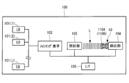
- FIG. 1 shows an example of the configuration of a digital holography device 100 that captures the holography of an object image 110A.
- the digital holography device 100 is a microscope, and includes j laser diodes (LD) 101 (1) to 101 (j), a switching element 102, an irradiation unit 103, and a detector 104. , An interface (I / F) 105.
- LD laser diodes
- I / F an interface
- LD 101 (1) to 101 (j) are all light sources that oscillate and emit coherent light, and are connected to the switching element 102 via a cable such as an optical fiber.
- the oscillation wavelengths ⁇ (1) to ⁇ (j) of the LDs 101 (1) to 101 (j) are set to become longer in this order, for example.
- the switching element 102 switches the LDs 101 (1) to 101 (j) used as light sources based on an instruction from a computer 200A or the like, which will be described later, connected via a network.
- the irradiation unit 103 emits the illumination light L toward the object image 110A or the like based on the LDs 101 (1) to 101 (j) switched by the switching element 102.
- the object image 110A is, for example, a cell or the like.
- the detector 104 is composed of, for example, a CCD image sensor, images the interference fringe (hologram) generated by the illumination light L emitted from the irradiation unit 103, and acquires the interference fringe intensity data 10 in the object image 110A.
- a light wave diffracted by the object image 110A is an object wave (an arc-shaped line on the right side of the object image 110A in the figure) and a non-diffracted light wave (including transmitted light) is a reference wave ( The line segment on the right side of the object image 110A) is recorded, and the interference fringes generated by these are recorded.
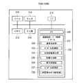
- FIG. 2 illustrates an example of a configuration of a computer 200A that is an example of a successive approximation calculation device that performs the successive approximation calculation and the light wave propagation calculation.
- the computer 200A includes a CPU (Central Processing Unit) 210 that constitutes an example of a calculation unit and controls the operation of the entire apparatus.
- the CPU 210 includes a memory 212 including a volatile storage device such as a RAM (Random Access Memory), a monitor 214 including an LCD (Liquid Crystal Display), an input unit 216 including a keyboard and a mouse, an interface 218,
- the storage unit 220 is connected to each.
- the interface 218 is configured to be communicable with the digital holography device 100, transmits a hologram imaging instruction to the digital holography device 100, and receives imaging data from the digital holography device 100.
- the computer 200A and the digital holography device 100 may be directly connected by a cable or the like, or may be wirelessly connected. Further, the data may be moved by an auxiliary storage device using a semiconductor memory such as a USB (Universal Serial Bus).
- the storage unit 220 includes a nonvolatile storage device such as a ROM (Read only Memory), a flash memory, an EPROM (Erasable Programmable ROM), an HDD (Hard Disc Drive), and an SSD (Solid State Drive).
- ROM Read only Memory
- EPROM Erasable Programmable ROM
- HDD Hard Disc Drive
- SSD Solid State Drive
- An OS (Operating System) 229 and an imaging control / data analysis program 221 are stored in the storage unit 220.
- the imaging control / data analysis program 221 executes the functions of the imaging instruction unit 232, the hologram acquisition unit 233, the phase information calculation unit 234, the image generation unit 235, the display control unit 236, the hologram storage unit 237, and the like.
- the imaging control / data analysis program 221 has a function of performing processing such as successive approximation calculation using the hologram imaged by the digital holography device 100 to reproduce the image of the object image 110A and display it on the screen of the monitor 214 as an image. Have. Further, the imaging control / data analysis program 221 has a function of controlling hologram imaging by the digital holography device 100.
- FIG. 3 is a diagram for explaining the outline of a generation step of generating learning data.
- the digital holography device 100 irradiates the object image 110A with light of different wavelengths ⁇ (1) to ⁇ (j) from the light source, and outputs interference fringe intensity data 10a (1) to 10a (j) of different patterns as one.
- the data group G (1) is acquired, and N data groups G (N) are acquired by the same method.
- N is a positive integer.
- the computer 200A uses the acquired data group G (1) to G (N) of the interference fringe intensity and the interference fringe phase initial value data 20a which is the preset initial value of the phase of the object image 110A. Performs successive approximation calculation.
- An arbitrary value can be set as the initial value of the phase in the object image 110A. In this embodiment, for example, all pixel values are set to 0 as the initial value of the phase. Further, the pixel value may be set randomly.
- the computer 200A calculates the interference fringe phase estimated value data 30a (1) to 30a (j) whose phases have been restored by performing successive approximation calculation for each of the data groups G (1) to G (N).
- the interference fringe intensity data 10a (1) to 10a (j) at each wavelength ⁇ acquired by actual measurement and the interference fringe phase estimated value data 30a (1) to 30a obtained by the successive approximation calculation. (J) is used as learning data when performing machine learning to construct the initial phase estimator 300. That is, in the present embodiment, the phase information obtained by sequentially calculating the initial phase value with the pixel value 0 or the like is used as the learning data of the initial phase estimator 300. In order to prepare the phase information close to the true value, it is desirable that the evaluation function be made small by performing a sufficient number of iterations at the learning data generation stage.
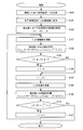
- FIG. 4 is a flowchart showing an example of the operation of the computer 200A when the phase of the object image 110A is calculated by the successive approximation calculation.
- FIGS. 1 to 3 Example of successive approximation calculation
- step S100 the computer 200A acquires the interference fringe intensity data 10 (1) in the object image 110A captured by the digital holography device 100.
- the CPU 210 of the computer 200A stores the received interference fringe intensity data 10 (1) in the hologram storage unit 237.
- the computer 200A sequentially performs the above-described hologram imaging process for each wavelength ⁇ , acquires the interference fringe intensity data 10 (1) to 10 (j) corresponding to all the light wavelengths, and the hologram storage unit 237. Save to.
- step S101 the CPU 210 converts the plurality of interference fringe intensity data 10 (1) to 10 (j) stored in the hologram storage unit 237 into amplitudes. Since the hologram has a distribution of intensity values, the intensity information as it is cannot be applied to the Fourier transform used in the light wave propagation calculation described later. Therefore, in step S101, each intensity value is converted into an amplitude value. The conversion to the amplitude is performed by calculating the square root of each pixel value.
- the initial phase estimator 300 which is a learned model, is used to estimate and set the initial value of the phase of the object image 110A.
- j is an identifier of the LD 101 that is a light source of the illumination light L (J1 ⁇ j ⁇ J2)
- a is a direction value that takes a value of 1 or ⁇ 1
- n (1 ⁇ n) is the number of repetitions of calculation. Is.
- step S103 the CPU 210 updates the amplitude of the object image 110A at the wavelength ⁇ (j). Specifically, the amplitude obtained by conversion from the intensity value of the hologram in step S101 is substituted into equation (1) shown below.
- step S104 the CPU 210 uses the updated amplitude (interference fringe intensity data 10 (j)) of the object image 110A and the estimated interference fringe phase initial value data 20a to calculate the back propagation to the object plane by the following equation ( Calculate based on 1).
- E (x, y, 0) is the complex amplitude distribution on the object plane
- E (x, y, z) is the complex amplitude distribution on the detection plane
- z is the propagation distance.
- .. k is the wave number.
- step S105 the CPU 210 determines whether or not the value of j + a falls within the range of J1 or more and J2 or less. When the CPU 210 determines that the value of j + a is outside the range of J1 or more and J2 or less, the process proceeds to step S106. In step S106, the CPU 210 inverts the sign of a and advances to step S107.
- step S105 when the CPU 210 determines that the value of j + a falls within the range of J1 or more and J2 or less, the process proceeds to step S107.
- step S107 the CPU 210 increments or decrements j depending on whether a is positive or negative.
- step S108 the CPU 210 updates the phase of the object image 110A with the wavelength ⁇ (j). Specifically, in the complex wavefront in the object plane calculated in step S104, the phase is converted to the next wavelength by calculation. At this time, the amplitude is not updated.
- step S109 the CPU 210 calculates the propagation to the detection surface in the state where only the phase of the object image 110A is converted to the next wavelength, based on the light wave propagation calculation of the equation (2) shown below.
- E (x, y, 0) is the complex amplitude distribution on the object plane
- E (x, y, z) is the complex amplitude distribution on the detection plane
- z corresponds to the propagation distance.
- .. k is the wave number.
- step S110 the CPU 210 makes a difference between the amplitude Uj of the object image 110A calculated by the light wave propagation calculation and the amplitude Ij based on the intensity value of the interference fringe intensity data 10 (j) which is the measured value of the wavelength ⁇ (j). It is determined whether the sum of (that is, the error) is less than the threshold value ⁇ , that is, whether the difference becomes the minimum value.
- the determination step is an example of the evaluation function. If the CPU 210 determines that the sum of the differences is not less than the threshold value ⁇ , the process proceeds to step S111.
- step S111 the CPU 210 increments n, returns to step S103, and repeats the above processing.
- step S110 when the total sum of the differences is less than the threshold value ⁇ , the CPU 210 determines that the phase of the object image 110A has been sufficiently recovered, that is, has become a value close to the true value, and ends the phase information calculation process. .. In this way, the interference fringe phase estimated value data 30 is acquired by performing the successive approximation calculation so that the evaluation function becomes the minimum.
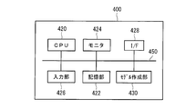
- FIG. 5 is a block diagram showing an example of the functional configuration of the computer 400 used to create the initial phase estimator 300.
- the computer 400 for example, a personal computer or a workstation in which predetermined software (program) is installed, or a high-performance computer system connected to these computers or the like via a communication line can be used.
- the computer 400 is an example of a calculation unit, and includes a CPU 420, a storage unit 422, a monitor 424, an input unit 426, an interface 428, and a model creation unit 430.
- the CPU 420, the storage unit 422, the monitor 424, the input unit 426, the interface 428, and the model creating unit 430 are connected to each other via the bus 450.
- the CPU 420 executes a program stored in a memory such as a ROM and a program of the model creating unit 430 to control the operation of the entire apparatus and perform machine learning for creating a learned model.
- the model creation unit 430 performs machine learning and builds a learned model for approximating a sequential operation of calculating interference fringe phase estimated value data from interference fringe intensity data of an object image.
- deep learning is used as a machine learning method, and a convolutional neural network (CNN) that is widely used is used.
- CNN convolutional neural network
- the convolutional neural network is one of the methods that can approximate an arbitrary image conversion function.
- the learned model created by the model creating unit 430 is stored in the computer 200B shown in FIG. 2, for example.
- the storage unit 422 is configured by a nonvolatile storage device such as a ROM (Read only Memory), a flash memory, an EPROM (Erasable Programmable ROM), a HDD (Hard Disc Drive), and an SSD (Solid State Drive).
- ROM Read only Memory
- EPROM Erasable Programmable ROM
- HDD Hard Disc Drive
- SSD Solid State Drive
- the monitor 424 is, for example, a monitor including a liquid crystal display or the like.
- the input unit 426 includes, for example, a keyboard, a mouse, a touch panel, etc., and performs various operations related to the execution of machine learning.
- the interface 428 includes a LAN, WAN, USB, etc., and performs bidirectional communication with, for example, the digital holography device 100 and the computer 200B.
- FIG. 6 is a diagram for explaining the outline of the learning stage for creating the initial phase estimator 300.
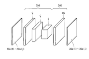
- FIG. 7 shows an example of a schematic configuration of the convolutional neural network 350 and the deconvolutional neural network 360 used when creating the initial phase estimator 300.
- the learning data described in FIG. 3 is used for learning the neural network connection weight parameter of the convolutional neural network 350 or the like.
- the interference fringe intensity data 10a (1) to 10a (j) which are physical quantities, are used for the input of the neural network
- the interference fringe phase estimated value data 30a (1) to 30a (j) are used for the output of the neural network.
- the interference fringe phase estimated value data 30a (1) to 30a (j) are image data showing a value close to a true value in the phase in the object image 110A.
- a convolutional neural network that uses intensity data of a part of the wavelengths of the interference fringe intensity data 10a (1) to 10a (j) as the input of the neural network may be used.
- the convolutional neural network 350 has a plurality of convolutional layers C.
- the convolutional layer C performs convolution by applying a filter to the input interference fringe intensity data 10a (1) to 10a (j), extracts local features in the image, and outputs a feature amount map.
- the filter has elements such as g ⁇ g pixels and has parameters such as weight and bias. Note that g is a positive integer.
- the deconvolution neural network 360 has a deconvolution layer DC.
- the deconvolution layer DC performs a calculation such as convolution on the converted image converted by the convolution layer C to expand the converted image to the same size as the interference fringe intensity data 10a (1) as the input image, for example.
- Each filter in the deconvolution layer DC has parameters such as weight and bias.
- the convolutional neural network 350 learns the neural network coupling weight parameter using the learning data generated in the learning data generation step, and calculates the interference fringe phase estimated value data from the interference fringe intensity data of the object image.
- the trained model corresponding to the image conversion function that approximates the sequential calculation is created.
- the created learned model is stored and updated in the learned model storage unit 238 indicated by the broken line of the computer 200B shown in FIG. 2, and is used as the initial phase estimator 300.
- FIG. 8 shows an example of an outline of an image reconstruction method by phase recovery of an object image using the successive approximation calculation method according to this embodiment.
- the digital holography device 100 shown in FIG. 1 is used to capture an object image 110B of new data, and then the computer 200B shown in FIG. 2 is used to reconstruct the image by phase recovery of the object image 110B.
- the means for capturing the object image 110B may be any device having the same function as the digital holography device 100.
- the computer 200B has the same configuration and function as the computer 200A, except that the computer 200B includes a learned model storage unit 238 shown by a broken line.
- the digital holography device 100 irradiates the object image 110B of the measurement target with light of different wavelengths ⁇ (1) to ⁇ (j) from the light source to obtain the interference fringe intensity data 10 ( 1) to 10 (j) are acquired.
- j is a positive integer.
- the interference fringe intensity data 10 of the object image 110B may be acquired in advance.
- the computer 200B uses the learned model stored in the learned model storage unit 238 indicated by the broken line in FIG. 2 as the initial phase estimator 300 to generate new interference fringe intensity data 10 (1) as input.
- appropriate phase information is set as the initial value of the successive approximation calculation.
- the interference fringe phase initial value data 20 as the phase information closer to the true value can be acquired as compared with the case where an arbitrary initial value is used as in the conventional case.
- the computer 200B receives the interference fringe intensity data 10 (1) to 10 (j) as physical quantities of the object image 110B and the interference fringe phase initial value data 20 which is the initial value of the phase of the object image 110B.
- the interference fringe phase estimated value data 30 of the phase-recovered object image 110B is calculated.
- Each processing of S101 to S111 of the flowchart shown in FIG. 4 can be applied to the algorithm of the successive approximation calculation.
- the computer 200B sequentially updates the interference fringe phase initial value data 20 as an approximate solution to minimize the evaluation function in step S110 shown in FIG. 4, and estimates the interference fringe phase in the object image 110B.
- the value data 30 is calculated.
- the computer 200B uses the interference fringe phase estimated value data 30 of the object image 110B obtained by the phase recovery and the interference fringe intensity data 10 (1) used as the input data of the initial phase estimator 300 to generate a light wave.
- the reconstructed reconstruction intensity data 40 and the reconstructed phase data 50 are acquired.
- the processing of each step described in FIG. 4, the equation (1), the equation (2) and the like can be used.
- the initial value of the phase of the object image 110B used in the successive approximation calculation is calculated by the initial phase estimator 300 that is pre-built by machine learning. It is possible to avoid converging to the wrong phase of the object image 110B, and it is possible to reduce the number of repetitive calculations required until the object image 110B converges to the phase.
- the phase information of the object image 110A estimated by the successive approximation calculation method is generated as teacher data, so the environment changes and a new phase estimator is constructed. Even when the need arises, the data of the intensity information can be collected by photographing in that environment, and the data of the phase information required as the learning data can be generated. Thereby, the initial phase estimator 300 suitable for the environment in which the data is acquired can be constructed. Further, since the phase value close to the true value can be obtained by calculating the phase of the object image 110A by the successive approximation calculation method, the initial phase estimator 300 with higher accuracy and stability can be created. ..
- the estimation of the initial value in the solution of the relational expression of the model is applied when the object image (image) of the cell or the like is reproduced, but the invention is not limited to this.
- the present invention can also be applied to the fields of image reconstruction in a PET apparatus, CT apparatus, etc., X-ray fluoroscopic image scattered ray estimation, chromatogram, mass spectrum and the like.
- the radiation signal is input to the initial phase estimator 300 and the reconstructed tomographic image is output.
- the initial phase estimator 300 is supplied with a fluoroscopic image (generated by transmitting radiation through an object) and outputs a fluoroscopic image (with artifacts removed). ..
- the evaluation function used in step S110 can be determined by whether or not the evaluation function is maximized, for example, when the index changes in an X-ray image.
- a neural network is used as the machine learning
- the present invention is not limited to this, and other machine learning such as support vector machine or boosting may be used. ..
- the initial value of the phase of the object image used in the successive approximation calculation is not limited to one, and may be multiple.
- iterative approximation calculation is performed with a plurality of initial values, and the initial value having a better solution result is selected.
- a fluoroscopic image in which radiation passes through the object image can be used instead of the interference fringe intensity data of the object image described above.
- the computer 200B obtains a reconstructed tomographic image of the object image by performing successive approximation calculation using a fluoroscopic image or the like.
- Interference fringe intensity data (physical quantity) 20, 20a Interference fringe phase initial value data 30 Interference fringe phase estimated value data 200A, 200B, 400 Computer (successive approximation calculation device, arithmetic unit) 210 CPU (arithmetic unit) 300 initial phase estimator 350 convolutional neural network (neural network)
Landscapes
- Engineering & Computer Science (AREA)
- Physics & Mathematics (AREA)
- Theoretical Computer Science (AREA)
- General Physics & Mathematics (AREA)
- Data Mining & Analysis (AREA)
- Mathematical Physics (AREA)
- Software Systems (AREA)
- General Engineering & Computer Science (AREA)
- Computing Systems (AREA)
- Health & Medical Sciences (AREA)
- General Health & Medical Sciences (AREA)
- Molecular Biology (AREA)
- Computational Linguistics (AREA)
- Biophysics (AREA)
- Biomedical Technology (AREA)
- Artificial Intelligence (AREA)
- Life Sciences & Earth Sciences (AREA)
- Evolutionary Computation (AREA)
- Computational Mathematics (AREA)
- Mathematical Analysis (AREA)
- Mathematical Optimization (AREA)
- Pure & Applied Mathematics (AREA)
- Algebra (AREA)
- Databases & Information Systems (AREA)
- Holo Graphy (AREA)
- Complex Calculations (AREA)
- Image Analysis (AREA)
Abstract
【課題】逐次近似計算法で用いる解の初期値を真値に近い値とすることが可能な逐次近似計算方法等を提供する。 【解決手段】コンピュータは、ディジタルホログラフィ装置により測定された干渉縞強度データ10等と、推定した物体像の位相の初期値である干渉縞位相初期値データ20とを用いて逐次近似計算を行うことにより、位相回復された物体像の干渉縞位相推定値データ30を算出する。干渉縞位相初期値データ20は、初期位相推定器300により算出される。初期位相推定器300は、学習用の干渉縞強度データ等を用いて機械学習を実施することにより構築される。コンピュータは、位相回復により得られた物体像の干渉縞位相推定値データ30と、初期位相推定器300の入力データとして用いた干渉縞強度データ10とを用いて光波伝搬計算を行うことにより、再構成された再構成強度データ40および再構成位相データ50を取得する。
Description
本発明は、逐次近似計算方法、逐次近似計算装置およびプログラムに関する。
従来から、解析的に数値解が求められない問題においては、モデルの関係式を解くに当たって最初に一つの任意の初期値(近似解)を設定し、次にこの初期値を用いてさらに精度の良い解を求め、逐次この計算を繰り返すことで一つの解に収束させる、逐次近似計算法が知られている。
上述した逐次近似計算法は、例えば、特許文献1に開示されるPET等の核医学用データの断層画像再構成、特許文献2に開示される放射線断層撮影装置における放射線の散乱成分推定、特許文献3に開示される断層画像処理における欠損データの補償、特許文献4に開示されるX線CT装置における再構成画像のアーティファクト低減等の分野で広く利用されている。
ところで、上述した逐次近似計算法で用いる解の初期値は、できるだけ真値に近い方が、誤った局所解へ収束することが少なく、かつ、解の収束に要する繰り返しの計算の回数も少なくて済む。しかしながら、従来では、対象とする問題に応じて様々な解を取りうるため、適切な初期値を設定するのが難しいという問題があった。
そこで、本発明は、上記課題を解決するものであって、逐次近似計算法で用いる解の初期値を真値に近い値とすることが可能な逐次近似計算方法、逐次近似計算装置およびプログラムを提供することを目的とする。
本発明の例示的な逐次近似計算方法は、評価関数を最小もしくは最大にするように逐次近似計算を行う工程を有し、前記工程において、前記逐次近似計算に用いる所定の物理量を入力とし、前記逐次近似計算に用いる一つまたは複数の初期値を出力とする学習済モデルを用いるものである。
また、本発明の例示的な逐次近似計算装置は、評価関数を最小もしくは最大にするように逐次近似計算を行う演算部を備え、前記演算部は、前記逐次近似計算に用いる所定の物理量を入力とし、前記逐次近似計算に用いる一つまたは複数の初期値を出力とする学習済モデルを有するものである。
また、本発明の例示的なプログラムは、コンピュータに、評価関数を最小もしくは最大にするように逐次近似計算を行い、当該逐次近似計算において、当該逐次近似計算に用いる所定の物理量を入力とし、前記逐次近似計算に用いる一つまたは複数の初期値を出力とする学習済モデルを用いる機能を、実行させるものである。
また、本発明の例示的な記憶媒体は、コンピュータ読み取り可能な非一時的記憶媒体であって、前記例示的なプログラムが記憶されたものである。
本発明によれば、逐次近似計算の初期値として、真値に近い値を設定することができるため、誤った局所解へ収束することを回避できると共に、解へ収束するまでに必要な繰り返し計算の回数を削減することができる。
以下に添付図面を参照しながら、本発明の好適な一実施の形態について詳細に説明する。本実施の形態では、以下の順番で説明を行う。
(1)学習用データを生成する学習用データ生成段階
(2)学習用データを用いて機械学習することで初期位相推定器を作成する学習段階
(3)初期位相推定器を用いた物体像の位相回復により画像の再構成を行う実施段階
(1)学習用データを生成する学習用データ生成段階
(2)学習用データを用いて機械学習することで初期位相推定器を作成する学習段階
(3)初期位相推定器を用いた物体像の位相回復により画像の再構成を行う実施段階
<(1)学習用データ生成段階>
まず、学習用データを生成する学習用データ生成段階について説明する。(1)の学習用データ生成段階では、後述する初期位相推定器を構築するために機械学習を行う際に用いられる学習用データを生成する。本実施の形態において学習用データとは、例えば、教師データを含み、例題となる干渉縞強度データと答えとなる逐次近似計算で推定した位相データとの大量のデータセットを示す。
まず、学習用データを生成する学習用データ生成段階について説明する。(1)の学習用データ生成段階では、後述する初期位相推定器を構築するために機械学習を行う際に用いられる学習用データを生成する。本実施の形態において学習用データとは、例えば、教師データを含み、例題となる干渉縞強度データと答えとなる逐次近似計算で推定した位相データとの大量のデータセットを示す。
[ディジタルホログラフィ装置100の構成例]
図1は、物体像110Aのホログラフィを撮像するディジタルホログラフィ装置100の構成の一例を示している。
図1は、物体像110Aのホログラフィを撮像するディジタルホログラフィ装置100の構成の一例を示している。
図1に示すように、ディジタルホログラフィ装置100は、顕微鏡であり、j個のレーザーダイオード(LD)101(1)~101(j)と、スイッチング素子102と、照射部103と、検出器104と、インターフェース(I/F)105とを備えている。
LD101(1)~101(j)は、いずれもコヒーレント光を発振・出射する光源であり、光ファイバ等のケーブルを介してスイッチング素子102に接続されている。LD101(1)~101(j)の各発振波長λ(1)~λ(j)は、例えばこの順に長くなるように設定されている。
スイッチング素子102は、ネットワークを介して接続される後述するコンピュータ200A等からの指示に基づいて、光源として使用するLD101(1)~101(j)を切り替える。
照射部103は、スイッチング素子102により切り替えられたLD101(1)~101(j)に基づいて、照明光Lを物体像110A等に向けて出射する。物体像110Aは、例えば細胞等である。
検出器104は、例えばCCDイメージセンサにより構成され、照射部103から出射された照明光Lによって生じた干渉縞(ホログラム)を撮像し、物体像110Aにおける干渉縞強度データ10を取得する。この干渉縞強度データ10は、物体像110Aによって回折した光波を物体波(同図中において物体像110Aの右側の円弧型の線)、回折しなかった光波(透過光を含む)を参照波(物体像110Aの右側の線分)とし、これらによって生じた干渉縞を記録したものである。
[コンピュータ200Aの構成例]
図2は、逐次近似計算および光波伝搬計算を行う逐次近似計算装置の一例であるコンピュータ200Aの構成の一例を示している。
図2は、逐次近似計算および光波伝搬計算を行う逐次近似計算装置の一例であるコンピュータ200Aの構成の一例を示している。
図2に示すように、コンピュータ200Aは、演算部の一例を構成し、装置全体の動作を制御するCPU(Central Processing Unit)210を備えている。CPU210には、RAM(Random Access Memory)等の揮発性記憶装置を含むメモリ212と、LCD(Liquid Crystal Display)等を含むモニタ214と、キーボードやマウス等を含む入力部216と、インターフェース218と、記憶部220とがそれぞれ接続されている。
インターフェース218は、ディジタルホログラフィ装置100との間で通信可能に構成され、ディジタルホログラフィ装置100にホログラム撮像の指示を送信すると共に、ディジタルホログラフィ装置100からの撮像データを受信する。コンピュータ200Aとディジタルホログラフィ装置100とは、ケーブル等により直接接続しても良いし、無線により接続しても良い。また、USB(Universal Serial Bus)等の半導体メモリを用いた補助記憶装置によってデータを移動可能な構成としても良い。
記憶部220は、ROM(Read only Memory)、フラッシュメモリ、EPROM(Erasable Programmable ROM)、HDD(Hard Disc Drive)、SSD(Solid State Drive)等の不揮発性記憶装置により構成されている。記憶部220には、OS(Operating System)229、および撮像制御・データ解析プログラム221が格納されている。
撮像制御・データ解析プログラム221は、撮像指示部232、ホログラム取得部233、位相情報算出部234、画像生成部235、表示制御部236およびホログラム記憶部237等の機能を実行する。撮像制御・データ解析プログラム221は、ディジタルホログラフィ装置100により撮像されたホログラムを用いて逐次近似計算等の処理を行い、物体像110Aの像を再生してモニタ214の画面上に画像として表示させる機能を有する。また、撮像制御・データ解析プログラム221は、ディジタルホログラフィ装置100によるホログラム撮像を制御する機能を有する。
[学習用データ生成段階の概略]
図3は、学習用データを生成する生成段階の概略を説明するための図である。ディジタルホログラフィ装置100は、波長λ(1)~λ(j)の異なる光のそれぞれを光源から物体像110Aに照射し、模様の異なる干渉縞強度データ10a(1)~10a(j)を一つのデータ群G(1)として取得し、さらに同様の手法によりN個のデータ群G(N)を取得する。Nは、正の整数である。
図3は、学習用データを生成する生成段階の概略を説明するための図である。ディジタルホログラフィ装置100は、波長λ(1)~λ(j)の異なる光のそれぞれを光源から物体像110Aに照射し、模様の異なる干渉縞強度データ10a(1)~10a(j)を一つのデータ群G(1)として取得し、さらに同様の手法によりN個のデータ群G(N)を取得する。Nは、正の整数である。
次に、コンピュータ200Aは、取得した干渉縞強度のデータ群G(1)~G(N)と、予め設定した物体像110Aの位相の初期値である干渉縞位相初期値データ20aとを用いて逐次近似計算を行う。物体像110Aにおける位相の初期値は、任意の値を設定することができる。本実施の形態では、例えば位相の初期値として全ての画素値を0に設定している。また、画素値をランダムに設定しても良い。コンピュータ200Aは、逐次近似計算を行うことにより、位相回復した干渉縞位相推定値データ30a(1)~30a(j)をデータ群G(1)~G(N)毎に算出する。
本実施の形態では、実際の測定により取得した各波長λにおける干渉縞強度データ10a(1)~10a(j)と、逐次近似計算により得られた干渉縞位相推定値データ30a(1)~30a(j)を、初期位相推定器300を構築するために機械学習を行う際の学習用データとして用いる。つまり、本実施の形態では、位相初期値を画素値0などにして逐次計算することで得た位相情報を初期位相推定器300の学習用データとして用いることになる。真値に近い位相情報を用意するために、学習用データ生成段階では、十分な繰返し回数の逐次演算を行い、評価関数が小さくなるようにすることが望ましい。
[逐次近似計算の実施例]
図4は、逐次近似計算により物体像110Aの位相を算出する場合におけるコンピュータ200Aの動作の一例を示すフローチャートである。以下では、図1~図3等を参照しつつ説明する。
図4は、逐次近似計算により物体像110Aの位相を算出する場合におけるコンピュータ200Aの動作の一例を示すフローチャートである。以下では、図1~図3等を参照しつつ説明する。
ステップS100において、コンピュータ200Aは、ディジタルホログラフィ装置100により撮像された、物体像110Aにおける干渉縞強度データ10(1)を取得する。コンピュータ200AのCPU210は、受信した干渉縞強度データ10(1)をホログラム記憶部237に保存する。このようにしてコンピュータ200Aは、上述したホログラム撮像処理を波長λ毎に順番に行い、全ての光波長に対応する干渉縞強度データ10(1)~10(j)を取得し、ホログラム記憶部237に保存する。
ステップS101において、CPU210は、ホログラム記憶部237に保存された複数の干渉縞強度データ10(1)~10(j)を振幅に変換する。ホログラムは強度値の分布であるため、強度情報のままでは後述の光波伝搬計算で用いるフーリエ変換に適用することができない。そのため、ステップS101において各強度値を振幅値に変換する。振幅への変換は、各画素値の平方根を算出することで行われる。
ステップS102において、CPU210は、j=1、a=1、n=1とし、検出面における物体像110Aにおける位相の初期値である干渉縞位相初期値データ20aを設定する。本実施の形態では、学習済みモデルである初期位相推定器300を用いて物体像110Aの位相の初期値を推定して設定する。なお、jは照明光Lの光源となるLD101の識別子であり(J1≦j≦J2)、aは1または-1の値をとる方向値であり、n(1≦n)は演算の繰り返し回数である。
ステップS103において、CPU210は、波長λ(j)における物体像110Aの振幅を更新する。具体的には、ステップS101にてホログラムの強度値からの変換で求めた振幅を下記に示す式(1)に代入する。
ステップS104において、CPU210は、更新した物体像110Aの振幅(干渉縞強度データ10(j))および推定した干渉縞位相初期値データ20aを用いて、物体面への逆伝搬を下記に示す式(1)に基づいて計算する。

上記(1)式において、E(x、y、0)は物体面における複素振幅分布であり、E(x、y、z)は検出面における複素振幅分布であり、zは伝搬距離に相当する。kは波数である。
ステップS105において、CPU210は、j+aの値がJ1以上J2以下の範囲に収まるか否かを判定する。CPU210は、j+aの値がJ1以上J2以下の範囲外であると判定した場合、ステップS106に進む。ステップS106において、CPU210は、aの正負を反転させてステップS107に進む。
一方、ステップS105において、CPU210は、j+aの値がJ1以上J2以下の範囲に収まると判定した場合、ステップS107に進む。
ステップS107において、CPU210は、aが正であるかまたは負であるかに応じてjをインクリメントまたはデクリメントする。
ステップS108において、CPU210は、波長λ(j)による物体像110Aの位相を更新する。具体的には、ステップS104で計算した物体面における複素波面において、計算により位相を次の波長のものに変換する。このとき、振幅については更新しない。
ステップS109において、CPU210は、物体像110Aの位相だけを次の波長に変換した状態で、検出面への伝搬を下記に示す式(2)の光波伝搬計算に基づいて計算する。

上記(2)式において、E(x、y、0)は物体面における複素振幅分布であり、E(x、y、z)は検出面における複素振幅分布であり、zは伝搬距離に相当する。kは波数である。
ステップS110において、CPU210は、光波伝搬計算により計算された物体像110Aの振幅Ujと、波長λ(j)の実測値である干渉縞強度データ10(j)の強度値に基づく振幅Ijとの差分(すなわち誤差)の総和が閾値ε未満か、つまり差分が最小値となったか否かを判定する。なお、本判定ステップは、評価関数の一例である。CPU210は、差分の総和が閾値ε未満でないと判定した場合、ステップS111に進む。
ステップS111において、CPU210は、nをインクリメントし、ステップS103に戻り、上述した処理を繰り返して実行する。
一方、ステップS110において、CPU210は、差分の総和が閾値ε未満である場合、物体像110Aの位相が十分に回復した、すなわち真値に近い値になったと判定し、位相情報算出処理を終了する。このようにして、評価関数が最小となるように逐次近似計算を行って干渉縞位相推定値データ30を取得する。
<(2)初期位相推定器300を作成する学習段階>
次に、初期位相推定器300を作成する学習段階について説明する。(2)の学習段階では、機械学習により、物体像の干渉縞強度データから干渉縞位相推定値データを算出する逐次演算を近似する画像変換関数に相当する学習済みモデルを構築する。以下に詳しく説明する。
次に、初期位相推定器300を作成する学習段階について説明する。(2)の学習段階では、機械学習により、物体像の干渉縞強度データから干渉縞位相推定値データを算出する逐次演算を近似する画像変換関数に相当する学習済みモデルを構築する。以下に詳しく説明する。
[コンピュータ400の構成例]
図5は、初期位相推定器300の作成に用いられるコンピュータ400の機能構成の一例を示すブロック図である。コンピュータ400としては、例えば、所定のソフトウェア(プログラム)がインストールされたパーソナルコンピュータ、ワークステーション、またはこれらのコンピュータ等と通信回線を介して接続された高性能なコンピュータシステムを用いることができる。
図5は、初期位相推定器300の作成に用いられるコンピュータ400の機能構成の一例を示すブロック図である。コンピュータ400としては、例えば、所定のソフトウェア(プログラム)がインストールされたパーソナルコンピュータ、ワークステーション、またはこれらのコンピュータ等と通信回線を介して接続された高性能なコンピュータシステムを用いることができる。
図5に示すように、コンピュータ400は、演算部の一例であり、CPU420と、記憶部422と、モニタ424と、入力部426と、インターフェース428と、モデル作成部430とを備えている。CPU420、記憶部422、モニタ424、入力部426、インターフェース428およびモデル作成部430のそれぞれは、バス450を介して互いに接続されている。
CPU420は、ROM等のメモリに記憶されているプログラムやモデル作成部430のプログラム等を実行することにより、装置全体の動作を制御すると共に学習済みモデルを作成するための機械学習等を実施する。
モデル作成部430は、機械学習を行い、物体像の干渉縞強度データから干渉縞位相推定値データを算出する逐次演算を近似するための学習済みモデルを構築する。本実施の形態では、機械学習の手法としてディープラーニングを用い、その中でも広く利用されている畳み込みニューラルネットワーク(CNN)を用いる。畳み込みニューラルネットワークは、任意の画像変換関数を近似できる手法の一つである。なお、モデル作成部430により作成された学習済みモデルは、例えば図2に示したコンピュータ200Bに保存される。
記憶部422は、ROM(Read only Memory)、フラッシュメモリ、EPROM(Erasable Programmable ROM)、HDD(Hard Disc Drive)、SSD(Solid State Drive)等の不揮発性記憶装置により構成されている。
モニタ424は、例えば、液晶ディスプレイ等から構成されるモニタである。入力部426は、例えば、キーボード、マウス、タッチパネル等により構成され、機械学習の実施に関する各種操作を行う。インターフェース428は、LANやWAN、USB等により構成され、例えばディジタルホログラフィ装置100やコンピュータ200Bとの間で双方向の通信を行う。
図6は、初期位相推定器300を作成する学習段階の概要を説明するための図である。図7は、初期位相推定器300を作成する際に用いられる畳み込みニューラルネットワーク350および逆畳み込みニューラルネットワーク360の概略構成の一例を示している。
図6および図7に示すように、畳み込みニューラルネットワーク350等のニューラルネットワーク結合重みパラメータの学習には、図3で説明した学習用データが用いられる。具体的には、ニューラルネットワークの入力に物理量である干渉縞強度データ10a(1)~10a(j)を用い、ニューラルネットワークの出力に干渉縞位相推定値データ30a(1)~30a(j)を用いる。干渉縞位相推定値データ30a(1)~30a(j)は、物体像110Aにおける位相において真値に近い値を示す画像データである。なお、ニューラルネットワークの入力に干渉縞強度データ10a(1)~10a(j)の中の一部の波長の強度データを用いる畳み込みニューラルネットワークとしても良い。
畳み込みニューラルネットワーク350は、複数の畳み込み層Cを有している。図7では、畳み込み層Cを3層で構成した例について説明するが、これに限定されることはない。畳み込み層Cは、入力される干渉縞強度データ10a(1)~10a(j)に対してフィルタを作用させることで畳み込みを行い、画像内の局所的な特徴を抽出して特徴量マップを出力する。フィルタはg×g画素等の要素を持ち、重みやバイアスといったパラメータを有する。なお、gは正の整数である。
逆畳み込みニューラルネットワーク360は、逆畳み込み層DCを有している。図7では、逆畳み込み層DCを1層で構成した例について説明するが、これに限定されることはない。逆畳み込み層DCは、畳み込み層Cにより変換された変換画像に対して畳み込みのような演算を行うことにより、変換画像を入力画像としての干渉縞強度データ10a(1)等と例えば同サイズに拡大させる。逆畳み込み層DCにおける各フィルタは、重みやバイアスといったパラメータを有する。
このようにして、畳み込みニューラルネットワーク350では、学習用データ生成段階で生成した学習用データを用いてニューラルネットワーク結合重みパラメータを学習し、物体像の干渉縞強度データから干渉縞位相推定値データを算出する逐次演算を近似する画像変換関数に相当する学習済みモデルを作成する。作成された学習済みモデルは、図2に示すコンピュータ200Bの破線で示す学習済みモデル記憶部238に保存、更新され、初期位相推定器300として利用される。
<(3)位相回復による画像の再構成を行う実施段階>
次に、物体像の位相回復に基づいて画像の再構成を行う実施段階について説明する。(3)の実施段階では、上記(2)で作成した学習済みモデルを初期位相推定器300として用いることで、物体像の新たな干渉縞強度データに対して逐次近似演算の初期値に適切な位相情報を推定する。以下に詳しく説明する。
次に、物体像の位相回復に基づいて画像の再構成を行う実施段階について説明する。(3)の実施段階では、上記(2)で作成した学習済みモデルを初期位相推定器300として用いることで、物体像の新たな干渉縞強度データに対して逐次近似演算の初期値に適切な位相情報を推定する。以下に詳しく説明する。
図8は、本実施の形態に係る逐次近似計算法を用いた物体像の位相回復による画像の再構成方法の概要の一例を示している。実施段階では、図1に示すディジタルホログラフィ装置100を用いて新たなデータの物体像110Bを撮像し、次に、図2に示すコンピュータ200Bを用いて物体像110Bの位相回復による画像の再構成を行うプログラムを実行する場合について説明する。なお、物体像110Bを撮像する手段は、ディジタルホログラフィ装置100と同等の機能を有する装置であれば良い。また、コンピュータ200Bは、破線で示す学習済みモデル記憶部238を備える以外は、コンピュータ200Aと共通する構成、機能を有する。
図8に示すように、ディジタルホログラフィ装置100は、波長λ(1)~λ(j)の異なる光のそれぞれを光源から測定対象の物体像110Bに照射し、模様の異なる干渉縞強度データ10(1)~10(j)を取得する。jは正の整数である。なお、物体像110Bの干渉縞強度データ10は、予め取得しておいても良い。
次に、コンピュータ200Bは、図2の破線で示す学習済みモデル記憶部238に保存されている学習済みモデルを初期位相推定器300として用い、入力された新たな干渉縞強度データ10(1)に対して逐次近似計算の初期値に適切な位相情報を設定する。これにより、従来のように任意の初期値を用いる場合よりも、真値に近い位相情報としての干渉縞位相初期値データ20を取得できる。
次に、コンピュータ200B(CPU210)は、物体像110Bの物理量としての干渉縞強度データ10(1)~10(j)と物体像110Bの位相の初期値である干渉縞位相初期値データ20とを用いて逐次近似計算を行うことにより、位相回復された物体像110Bの干渉縞位相推定値データ30を算出する。逐次近似計算のアルゴリズムには、図4に示したフローチャートのS101~S111の各処理を適用することができる。このようにして、コンピュータ200Bは、図4に示したステップS110における評価関数を最小にするために、近似解としての干渉縞位相初期値データ20を逐次更新し、物体像110Bにおける干渉縞位相推定値データ30を算出する。
次に、コンピュータ200Bは、位相回復により得られた物体像110Bの干渉縞位相推定値データ30と、初期位相推定器300の入力データとして用いた干渉縞強度データ10(1)とを用いて光波伝搬計算を行うことにより、再構成された再構成強度データ40および再構成位相データ50を取得する。光波伝搬計算には、図4で説明した各ステップの処理、および式(1)、式(2)等を用いることができる。
以上説明したように、本実施の形態によれば、実施段階において、逐次近似計算で用いる物体像110Bの位相の初期値を、機械学習により予め構築された初期位相推定器300により算出するので、誤った物体像110Bの位相へ収束することを回避できると共に、物体像110B位相へ収束するまでに必要な繰り返し計算の回数を削減することができる。
また、本実施の形態によれば、学習用データ生成段階において、逐次近似計算法により推定した物体像110Aの位相情報を教師データとして生成するので、環境が変わって新たに位相推定器を構築する必要が生じた場合にも、その環境で撮影して強度情報のデータを収集するとともに、学習用データとして必要な位相情報のデータも生成することができる。これにより、データを取得した環境に適した初期位相推定器300を構築することができる。また、逐次近似計算法により物体像110Aの位相を算出することで、真値に近い位相の値を得ることができるので、より精度の高くかつ安定した初期位相推定器300を作成することができる。
なお、本発明の技術範囲は、上述した実施形態に限定されるものではなく、本発明の趣旨を逸脱しない範囲において、上述した実施形態に種々の変更を加えたものを含む。
上述した実施の形態では、モデルの関係式の解における初期値の推定を細胞等の物体像(画像)の再生時に適用したが、これに限定されることはない。例えば、PET装置やCT装置等における画像再構成、X線透視像散乱線推定、クロマトグラムやマススペクトル等の分野においても本発明を適用することができる。PET装置およびX線CT装置の場合、初期位相推定器300には放射線信号が入力され、再構成断層像が出力される。X線透視像散乱線推定の場合、初期位相推定器300には(放射線が物体を透過して生成される)放射線透視画像が入力され、(アーティファクトが除去された)放射線透視画像が出力される。
また、ステップS110で用いた評価関数は、例えばX線画像であって指標が変わるような場合には、評価関数が最大化するか否かで判定することができる。また、上述した実施の形態では、機械学習としてニューラルネットワークを用いた例について説明したが、これに限定されることはなく、例えばサポートベクターマシーンやブースティング等の他の機械学習を用いることもできる。
また、逐次近似計算に用いる物体像の位相の初期値は、一つに限定されることはなく、複数であっても良い。複数の初期値を用いる場合、複数の初期値で逐次近似計算を行い、解の結果が良い方の初期値を選択する。
さらに、逐次近似計算に用いる物理量としては、上述した物体像の干渉縞強度データに代えて、放射線が物体像を透過した放射線透視画像を用いることができる。この場合、コンピュータ200Bは、放射線透視画像等を用いて逐次近似計算を行うことにより、物体像の再構成断層像を求める。
10 干渉縞強度データ(物理量)
20,20a 干渉縞位相初期値データ
30 干渉縞位相推定値データ
200A,200B,400 コンピュータ(逐次近似計算装置,演算部)
210 CPU(演算部)
300 初期位相推定器
350 畳み込みニューラルネットワーク(ニューラルネットワーク)
20,20a 干渉縞位相初期値データ
30 干渉縞位相推定値データ
200A,200B,400 コンピュータ(逐次近似計算装置,演算部)
210 CPU(演算部)
300 初期位相推定器
350 畳み込みニューラルネットワーク(ニューラルネットワーク)
Claims (7)
- 評価関数を最小もしくは最大にするように逐次近似計算を行う工程を有し、
前記工程において、前記逐次近似計算に用いる所定の物理量を入力とし、前記逐次近似計算に用いる一つまたは複数の初期値を出力とする学習済モデルを用いる、
逐次近似計算方法。 - 前記物理量は、物体の干渉縞強度であり、
前記工程において、前記逐次近似計算により、前記物体の位相情報を求める、請求項1に記載の逐次近似計算方法。 - 前記物理量は、放射線が物体を透過した放射線透視画像であり、
前記工程において、前記逐次近似計算により、前記物体の再構成断層像を求める、請求項1に記載の逐次近似計算方法。 - 評価関数を最小もしくは最大にするように逐次近似計算を行う演算部を備え、
前記演算部は、前記逐次近似計算に用いる所定の物理量を入力とし、前記逐次近似計算に用いる一つまたは複数の初期値を出力とする学習済モデルを有する、逐次近似計算装置。 - 前記物理量は、物体の干渉縞強度であり、
前記演算部は、前記逐次近似計算により、前記物体の位相情報を求める、請求項4に記載の逐次近似計算装置。 - 前記物理量は、放射線が物体を透過した放射線透視画像であり、
前記演算部は、前記逐次近似計算により、前記物体の再構成断層像を求める、請求項4に記載の逐次近似計算装置。 - コンピュータに、
評価関数を最小もしくは最大にするように逐次近似計算を行い、当該逐次近似計算において、当該逐次近似計算に用いる所定の物理量を入力とし、前記逐次近似計算に用いる一つまたは複数の初期値を出力とする学習済モデルを用いる機能を、
実行させるためのプログラム。
Priority Applications (3)
| Application Number | Priority Date | Filing Date | Title |
|---|---|---|---|
| JP2020558331A JPWO2020105534A1 (ja) | 2018-11-22 | 2019-11-14 | 逐次近似計算方法、逐次近似計算装置およびプログラム |
| US17/294,181 US20220253508A1 (en) | 2018-11-22 | 2019-11-14 | Consecutive approximation calculation method, consecutive approximation calculation device, and program |
| CN201980089772.8A CN113316779A (zh) | 2018-11-22 | 2019-11-14 | 逐次逼近计算方法、逐次逼近计算装置以及程序 |
Applications Claiming Priority (2)
| Application Number | Priority Date | Filing Date | Title |
|---|---|---|---|
| JP2018218944 | 2018-11-22 | ||
| JP2018-218944 | 2018-11-22 |
Publications (1)
| Publication Number | Publication Date |
|---|---|
| WO2020105534A1 true WO2020105534A1 (ja) | 2020-05-28 |
Family
ID=70773063
Family Applications (1)
| Application Number | Title | Priority Date | Filing Date |
|---|---|---|---|
| PCT/JP2019/044657 Ceased WO2020105534A1 (ja) | 2018-11-22 | 2019-11-14 | 逐次近似計算方法、逐次近似計算装置およびプログラム |
Country Status (4)
| Country | Link |
|---|---|
| US (1) | US20220253508A1 (ja) |
| JP (1) | JPWO2020105534A1 (ja) |
| CN (1) | CN113316779A (ja) |
| WO (1) | WO2020105534A1 (ja) |
Cited By (1)
| Publication number | Priority date | Publication date | Assignee | Title |
|---|---|---|---|---|
| JP2022001040A (ja) * | 2020-06-19 | 2022-01-06 | 株式会社島津製作所 | 細胞の評価方法及び細胞解析装置 |
Families Citing this family (1)
| Publication number | Priority date | Publication date | Assignee | Title |
|---|---|---|---|---|
| JP7431694B2 (ja) * | 2020-07-28 | 2024-02-15 | キヤノン株式会社 | 情報処理装置、膜形成装置、物品の製造方法、およびプログラム |
Citations (2)
| Publication number | Priority date | Publication date | Assignee | Title |
|---|---|---|---|---|
| JPH08136174A (ja) * | 1994-11-14 | 1996-05-31 | Hitachi Ltd | 熱供給プラントの運転制御方法 |
| WO2016084420A1 (ja) * | 2014-11-27 | 2016-06-02 | 株式会社島津製作所 | ディジタルホログラフィ装置及びディジタルホログラム生成方法 |
-
2019
- 2019-11-14 US US17/294,181 patent/US20220253508A1/en not_active Abandoned
- 2019-11-14 CN CN201980089772.8A patent/CN113316779A/zh not_active Withdrawn
- 2019-11-14 JP JP2020558331A patent/JPWO2020105534A1/ja active Pending
- 2019-11-14 WO PCT/JP2019/044657 patent/WO2020105534A1/ja not_active Ceased
Patent Citations (2)
| Publication number | Priority date | Publication date | Assignee | Title |
|---|---|---|---|---|
| JPH08136174A (ja) * | 1994-11-14 | 1996-05-31 | Hitachi Ltd | 熱供給プラントの運転制御方法 |
| WO2016084420A1 (ja) * | 2014-11-27 | 2016-06-02 | 株式会社島津製作所 | ディジタルホログラフィ装置及びディジタルホログラム生成方法 |
Non-Patent Citations (1)
| Title |
|---|
| FUJIMOTO, KEN'ICHI: "Development of Deep Neural network for Initial Values Generation of Dynamical Image-Reconstruction System", IEICE TECHNICAL REPORT, vol. 118, no. 174, 1 August 2018 (2018-08-01), pages 21 - 24, ISSN: 0913-5685 * |
Cited By (2)
| Publication number | Priority date | Publication date | Assignee | Title |
|---|---|---|---|---|
| JP2022001040A (ja) * | 2020-06-19 | 2022-01-06 | 株式会社島津製作所 | 細胞の評価方法及び細胞解析装置 |
| JP7738845B2 (ja) | 2020-06-19 | 2025-09-16 | 株式会社島津製作所 | 細胞の評価方法及び細胞解析装置 |
Also Published As
| Publication number | Publication date |
|---|---|
| JPWO2020105534A1 (ja) | 2021-09-30 |
| US20220253508A1 (en) | 2022-08-11 |
| CN113316779A (zh) | 2021-08-27 |
Similar Documents
| Publication | Publication Date | Title |
|---|---|---|
| Song et al. | Solving inverse problems in medical imaging with score-based generative models | |
| Ben Yedder et al. | Deep learning for biomedical image reconstruction: A survey | |
| Wang et al. | Limited-angle CT reconstruction via the l_1/l_2 minimization | |
| RU2709437C1 (ru) | Способ обработки изображений, устройство обработки изображений и носитель данных | |
| JP6375619B2 (ja) | オクルージョンを意識した明視野像からの3次元シーンの再構成 | |
| Calvetti et al. | Hierachical Bayesian models and sparsity: ℓ 2-magic | |
| RU2510080C2 (ru) | Устройство для обработки изображения, способ обработки изображения и среда долговременного хранения информации | |
| US10902648B2 (en) | Robust reconstruction for dark-field and phase contrast CT | |
| JP6746676B2 (ja) | 画像処理装置、画像処理方法、及びプログラム | |
| Topal et al. | Deep learning-based inaccuracy compensation in reconstruction of high resolution XCT data | |
| CN109900355B (zh) | 成像方法及装置 | |
| Unser et al. | GlobalBioIm: A unifying computational framework for solving inverse problems | |
| Uribe et al. | A hybrid Gibbs sampler for edge-preserving tomographic reconstruction with uncertain view angles | |
| Beinert et al. | Total variation-based reconstruction and phase retrieval for diffraction tomography | |
| JPWO2020105534A1 (ja) | 逐次近似計算方法、逐次近似計算装置およびプログラム | |
| CN113029364B (zh) | 分布式鲁棒的像素超分辨成像方法及计算机设备 | |
| Mou et al. | Dictionary learning based low-dose x-ray CT reconstruction using a balancing principle | |
| Miao et al. | Alternating Iteration for $ l_ {p} $($0< p\leq 1$) Regularized CT Reconstruction | |
| Vo et al. | Plug-and-play learned proximal trajectory for 3D sparse-view X-ray computed tomography | |
| KR101685830B1 (ko) | 낮은 행렬계수를 이용한 내부 단층 촬영 영상 복원 장치 및 그 제어 방법 | |
| Escobedo et al. | Tiled-block image reconstruction by wavelet-based, parallel-filtered back-projection | |
| Guven et al. | Discretization error analysis and adaptive meshing algorithms for fluorescence diffuse optical tomography: Part I | |
| Banerjee et al. | FCDM: A Physics-Guided Bidirectional Frequency Aware Convolution and Diffusion-Based Model for Sinogram Inpainting | |
| JP2019013268A (ja) | 画像生成装置、画像生成方法及びプログラム | |
| Hu et al. | Constraint-Free Coherent Diffraction Imaging via Physics-Guided Neural Fields |
Legal Events
| Date | Code | Title | Description |
|---|---|---|---|
| 121 | Ep: the epo has been informed by wipo that ep was designated in this application |
Ref document number: 19886243 Country of ref document: EP Kind code of ref document: A1 |
|
| ENP | Entry into the national phase |
Ref document number: 2020558331 Country of ref document: JP Kind code of ref document: A |
|
| NENP | Non-entry into the national phase |
Ref country code: DE |
|
| 122 | Ep: pct application non-entry in european phase |
Ref document number: 19886243 Country of ref document: EP Kind code of ref document: A1 |