WO2020105503A1 - 表示制御プログラム、表示制御装置、及び表示制御方法 - Google Patents
表示制御プログラム、表示制御装置、及び表示制御方法Info
- Publication number
- WO2020105503A1 WO2020105503A1 PCT/JP2019/044294 JP2019044294W WO2020105503A1 WO 2020105503 A1 WO2020105503 A1 WO 2020105503A1 JP 2019044294 W JP2019044294 W JP 2019044294W WO 2020105503 A1 WO2020105503 A1 WO 2020105503A1
- Authority
- WO
- WIPO (PCT)
- Prior art keywords
- player character
- particles
- player
- control unit
- display control
- Prior art date
- Legal status (The legal status is an assumption and is not a legal conclusion. Google has not performed a legal analysis and makes no representation as to the accuracy of the status listed.)
- Ceased
Links
Images




Classifications
-
- G—PHYSICS
- G02—OPTICS
- G02B—OPTICAL ELEMENTS, SYSTEMS OR APPARATUS
- G02B27/00—Optical systems or apparatus not provided for by any of the groups G02B1/00 - G02B26/00, G02B30/00
- G02B27/01—Head-up displays
- G02B27/017—Head mounted
- G02B27/0172—Head mounted characterised by optical features
-
- A—HUMAN NECESSITIES
- A63—SPORTS; GAMES; AMUSEMENTS
- A63F—CARD, BOARD, OR ROULETTE GAMES; INDOOR GAMES USING SMALL MOVING PLAYING BODIES; VIDEO GAMES; GAMES NOT OTHERWISE PROVIDED FOR
- A63F13/00—Video games, i.e. games using an electronically generated display having two or more dimensions
- A63F13/25—Output arrangements for video game devices
-
- A—HUMAN NECESSITIES
- A63—SPORTS; GAMES; AMUSEMENTS
- A63F—CARD, BOARD, OR ROULETTE GAMES; INDOOR GAMES USING SMALL MOVING PLAYING BODIES; VIDEO GAMES; GAMES NOT OTHERWISE PROVIDED FOR
- A63F13/00—Video games, i.e. games using an electronically generated display having two or more dimensions
- A63F13/40—Processing input control signals of video game devices, e.g. signals generated by the player or derived from the environment
- A63F13/42—Processing input control signals of video game devices, e.g. signals generated by the player or derived from the environment by mapping the input signals into game commands, e.g. mapping the displacement of a stylus on a touch screen to the steering angle of a virtual vehicle
- A63F13/428—Processing input control signals of video game devices, e.g. signals generated by the player or derived from the environment by mapping the input signals into game commands, e.g. mapping the displacement of a stylus on a touch screen to the steering angle of a virtual vehicle involving motion or position input signals, e.g. signals representing the rotation of an input controller or a player's arm motions sensed by accelerometers or gyroscopes
-
- A—HUMAN NECESSITIES
- A63—SPORTS; GAMES; AMUSEMENTS
- A63F—CARD, BOARD, OR ROULETTE GAMES; INDOOR GAMES USING SMALL MOVING PLAYING BODIES; VIDEO GAMES; GAMES NOT OTHERWISE PROVIDED FOR
- A63F13/00—Video games, i.e. games using an electronically generated display having two or more dimensions
- A63F13/50—Controlling the output signals based on the game progress
- A63F13/52—Controlling the output signals based on the game progress involving aspects of the displayed game scene
- A63F13/525—Changing parameters of virtual cameras
- A63F13/5255—Changing parameters of virtual cameras according to dedicated instructions from a player, e.g. using a secondary joystick to rotate the camera around a player's character
-
- A—HUMAN NECESSITIES
- A63—SPORTS; GAMES; AMUSEMENTS
- A63F—CARD, BOARD, OR ROULETTE GAMES; INDOOR GAMES USING SMALL MOVING PLAYING BODIES; VIDEO GAMES; GAMES NOT OTHERWISE PROVIDED FOR
- A63F13/00—Video games, i.e. games using an electronically generated display having two or more dimensions
- A63F13/55—Controlling game characters or game objects based on the game progress
- A63F13/57—Simulating properties, behaviour or motion of objects in the game world, e.g. computing tyre load in a car race game
- A63F13/577—Simulating properties, behaviour or motion of objects in the game world, e.g. computing tyre load in a car race game using determination of contact between game characters or objects, e.g. to avoid collision between virtual racing cars
-
- A—HUMAN NECESSITIES
- A63—SPORTS; GAMES; AMUSEMENTS
- A63F—CARD, BOARD, OR ROULETTE GAMES; INDOOR GAMES USING SMALL MOVING PLAYING BODIES; VIDEO GAMES; GAMES NOT OTHERWISE PROVIDED FOR
- A63F13/00—Video games, i.e. games using an electronically generated display having two or more dimensions
- A63F13/60—Generating or modifying game content before or while executing the game program, e.g. authoring tools specially adapted for game development or game-integrated level editor
- A63F13/65—Generating or modifying game content before or while executing the game program, e.g. authoring tools specially adapted for game development or game-integrated level editor automatically by game devices or servers from real world data, e.g. measurement in live racing competition
-
- G—PHYSICS
- G02—OPTICS
- G02B—OPTICAL ELEMENTS, SYSTEMS OR APPARATUS
- G02B27/00—Optical systems or apparatus not provided for by any of the groups G02B1/00 - G02B26/00, G02B30/00
- G02B27/0093—Optical systems or apparatus not provided for by any of the groups G02B1/00 - G02B26/00, G02B30/00 with means for monitoring data relating to the user, e.g. head-tracking, eye-tracking
-
- G—PHYSICS
- G02—OPTICS
- G02B—OPTICAL ELEMENTS, SYSTEMS OR APPARATUS
- G02B27/00—Optical systems or apparatus not provided for by any of the groups G02B1/00 - G02B26/00, G02B30/00
- G02B27/01—Head-up displays
- G02B27/017—Head mounted
-
- G—PHYSICS
- G02—OPTICS
- G02B—OPTICAL ELEMENTS, SYSTEMS OR APPARATUS
- G02B27/00—Optical systems or apparatus not provided for by any of the groups G02B1/00 - G02B26/00, G02B30/00
- G02B27/01—Head-up displays
- G02B27/0179—Display position adjusting means not related to the information to be displayed
-
- G—PHYSICS
- G06—COMPUTING OR CALCULATING; COUNTING
- G06F—ELECTRIC DIGITAL DATA PROCESSING
- G06F3/00—Input arrangements for transferring data to be processed into a form capable of being handled by the computer; Output arrangements for transferring data from processing unit to output unit, e.g. interface arrangements
- G06F3/01—Input arrangements or combined input and output arrangements for interaction between user and computer
-
- G—PHYSICS
- G06—COMPUTING OR CALCULATING; COUNTING
- G06F—ELECTRIC DIGITAL DATA PROCESSING
- G06F3/00—Input arrangements for transferring data to be processed into a form capable of being handled by the computer; Output arrangements for transferring data from processing unit to output unit, e.g. interface arrangements
- G06F3/01—Input arrangements or combined input and output arrangements for interaction between user and computer
- G06F3/048—Interaction techniques based on graphical user interfaces [GUI]
- G06F3/0481—Interaction techniques based on graphical user interfaces [GUI] based on specific properties of the displayed interaction object or a metaphor-based environment, e.g. interaction with desktop elements like windows or icons, or assisted by a cursor's changing behaviour or appearance
-
- G—PHYSICS
- G06—COMPUTING OR CALCULATING; COUNTING
- G06T—IMAGE DATA PROCESSING OR GENERATION, IN GENERAL
- G06T13/00—Animation
- G06T13/20—Three-dimensional [3D] animation
-
- G—PHYSICS
- G06—COMPUTING OR CALCULATING; COUNTING
- G06T—IMAGE DATA PROCESSING OR GENERATION, IN GENERAL
- G06T13/00—Animation
- G06T13/20—Three-dimensional [3D] animation
- G06T13/40—Three-dimensional [3D] animation of characters, e.g. humans, animals or virtual beings
-
- G—PHYSICS
- G06—COMPUTING OR CALCULATING; COUNTING
- G06T—IMAGE DATA PROCESSING OR GENERATION, IN GENERAL
- G06T19/00—Manipulating three-dimensional [3D] models or images for computer graphics
-
- A—HUMAN NECESSITIES
- A63—SPORTS; GAMES; AMUSEMENTS
- A63F—CARD, BOARD, OR ROULETTE GAMES; INDOOR GAMES USING SMALL MOVING PLAYING BODIES; VIDEO GAMES; GAMES NOT OTHERWISE PROVIDED FOR
- A63F13/00—Video games, i.e. games using an electronically generated display having two or more dimensions
- A63F13/50—Controlling the output signals based on the game progress
- A63F13/54—Controlling the output signals based on the game progress involving acoustic signals, e.g. for simulating revolutions per minute [RPM] dependent engine sounds in a driving game or reverberation against a virtual wall
-
- A—HUMAN NECESSITIES
- A63—SPORTS; GAMES; AMUSEMENTS
- A63F—CARD, BOARD, OR ROULETTE GAMES; INDOOR GAMES USING SMALL MOVING PLAYING BODIES; VIDEO GAMES; GAMES NOT OTHERWISE PROVIDED FOR
- A63F2300/00—Features of games using an electronically generated display having two or more dimensions, e.g. on a television screen, showing representations related to the game
- A63F2300/60—Methods for processing data by generating or executing the game program
- A63F2300/66—Methods for processing data by generating or executing the game program for rendering three dimensional images
- A63F2300/6638—Methods for processing data by generating or executing the game program for rendering three dimensional images for simulating particle systems, e.g. explosion, fireworks
-
- A—HUMAN NECESSITIES
- A63—SPORTS; GAMES; AMUSEMENTS
- A63F—CARD, BOARD, OR ROULETTE GAMES; INDOOR GAMES USING SMALL MOVING PLAYING BODIES; VIDEO GAMES; GAMES NOT OTHERWISE PROVIDED FOR
- A63F2300/00—Features of games using an electronically generated display having two or more dimensions, e.g. on a television screen, showing representations related to the game
- A63F2300/80—Features of games using an electronically generated display having two or more dimensions, e.g. on a television screen, showing representations related to the game specially adapted for executing a specific type of game
- A63F2300/8082—Virtual reality
-
- G—PHYSICS
- G02—OPTICS
- G02B—OPTICAL ELEMENTS, SYSTEMS OR APPARATUS
- G02B27/00—Optical systems or apparatus not provided for by any of the groups G02B1/00 - G02B26/00, G02B30/00
- G02B27/01—Head-up displays
- G02B27/0101—Head-up displays characterised by optical features
- G02B2027/0138—Head-up displays characterised by optical features comprising image capture systems, e.g. camera
-
- G—PHYSICS
- G02—OPTICS
- G02B—OPTICAL ELEMENTS, SYSTEMS OR APPARATUS
- G02B27/00—Optical systems or apparatus not provided for by any of the groups G02B1/00 - G02B26/00, G02B30/00
- G02B27/01—Head-up displays
- G02B27/0101—Head-up displays characterised by optical features
- G02B2027/014—Head-up displays characterised by optical features comprising information/image processing systems
-
- G—PHYSICS
- G02—OPTICS
- G02B—OPTICAL ELEMENTS, SYSTEMS OR APPARATUS
- G02B27/00—Optical systems or apparatus not provided for by any of the groups G02B1/00 - G02B26/00, G02B30/00
- G02B27/01—Head-up displays
- G02B27/0179—Display position adjusting means not related to the information to be displayed
- G02B2027/0187—Display position adjusting means not related to the information to be displayed slaved to motion of at least a part of the body of the user, e.g. head, eye
Definitions
- the present invention relates to display control technology, and more particularly to a display control program for controlling display on a display device, a display control device, and a display control method.
- a game that can be played by operating the controller etc. while wearing the head mounted display connected to the game machine on the head and watching the screen displayed on the head mounted display is gaining popularity.
- By using a head-mounted display it is possible to increase the immersive feeling in the visual world and further enhance the entertainment value of the game.
- an object of the present invention is to provide a display technique capable of giving a comfortable feeling to a viewer.
- a display control program includes an image generation unit that causes a computer to generate an image in a virtual three-dimensional space, and a plurality of particles arranged in the virtual three-dimensional space.
- An object control unit that controls an object
- a player character control unit that controls a player character that can be operated by the player and that is arranged in a virtual three-dimensional space
- a determination unit that determines whether or not the player character and the object are in contact with each other.
- an absorption control unit that executes an action indicating that a plurality of particles included in the object in contact with the player character are absorbed by the player character, To realize.
- This device is an image generation unit that generates an image of a virtual three-dimensional space, an object control unit that is arranged in the virtual three-dimensional space, controls an object including a plurality of particles, and is arranged in the virtual three-dimensional space.
- the player character control unit that controls the player character that can be operated by the player
- the determination unit that determines whether or not the player character and the object have contacted each other
- the determination unit that the player character and the object have contacted each other
- An absorption control unit that executes an action that represents a state in which a plurality of particles included in an object that has come into contact with the player character are absorbed by the player character.
- Yet another aspect of the present invention is a display control method.
- This method includes the steps of generating an image of a virtual three-dimensional space on a computer, controlling an object including a plurality of particles arranged in the virtual three-dimensional space, and a player arranged in the virtual three-dimensional space. Controlling the operable player character, determining whether the player character has come into contact with the object, and determining that the player character has come into contact with the object, the object that has come into contact with the player character Causing the computer to execute an action representing a state in which the plurality of particles included therein are absorbed by the player character.
- FIG. 3 is an external view of the head mounted display according to the embodiment.
- FIG. It is a functional block diagram of a head mounted display. It is a figure which shows the external appearance structure of an input device. It is a figure which shows the internal structure of an input device. It is a functional block diagram of a game device. It is a figure which shows the example of the game screen displayed on the display device of a head mounted display. It is a figure which shows the example of the object arrange
- the game device is an example of a display control device, and generates and displays an image of the game world in which objects and characters are arranged in a virtual three-dimensional space.
- objects such as animals and plants, and player characters that represent the player's body are composed of multiple light particles, and the image representation of the game world that represents a fantastic mental world is presented to the player.
- This visual expression corresponds to the fact that all substances are composed of elementary particles, and reminds the player that particles are the source of energy in the game world.
- the game device displays that particles forming the object are sucked into the player character while shining.
- players can experience a novel and comfortable feeling of healing, such as touching animals and plants, resonating with each other, and absorbing energy. This allows the player to improve his / her mental state through the game.
- Such image representation may be displayed on a stationary display device or a portable display device, but it is more effective to use a head mounted display (HMD).
- the game device sets the viewpoint position at the position of the eyes of the player character, and while changing the line-of-sight direction according to the direction of the head mounted display, renders and generates the virtual three-dimensional space in which the objects are arranged.
- the first-person view image is displayed on the head-mounted display.
- the player can have a deep immersive feeling as if he / she actually exists in the fantastic imagery world.
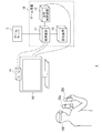
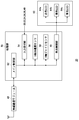
- FIG. 1 shows a configuration example of a game system 1 according to the embodiment.
- the game system 1 captures a game device 10, a head-mounted display 100, input devices 20a and 20b (collectively referred to as “input device 20”) that a player holds and operates, and a player wearing the head-mounted display 100. And an output device 15 for displaying an image.
- the output device 15 may be a television.
- the game device 10 is connected to an external network such as the Internet via an access point (AP) or the like.
- AP access point
- the game device 10 of the present embodiment is connected to a game server 3 provided to enable players of a plurality of game devices 10 to share a game world and execute a game at the same time.
- the game server 3 acquires information such as the position of the player character from each of the game devices 10 participating in the game, and distributes the acquired information to each game device 10.
- the head mounted display 100 is mounted on the head of the player to provide the player with a virtual reality (VR) image world.
- VR virtual reality
- the game device 10 includes a processing device 11, an output control device 12, and a storage device 13.
- the processing device 11 receives the operation information input by the player to the input device 20, the position information and the posture information of the input device 20 and the head mounted display 100, and executes the game application.
- the processing device 11 and the input device 20 may be connected by a cable or may be connected by a known wireless communication protocol.
- the output control device 12 is a processing unit that outputs the image data generated by the processing device 11 to the head-mounted display 100.
- the output control device 12 and the head-mounted display 100 may be connected by a cable, or a known wireless communication device. You may be connected by a communication protocol.
- the storage device 13 stores the program data of the game application, the shape data of the virtual three-dimensional space used by the game application, the shape data of the arranged objects and characters, and the like.
- the image capturing device 14 is a stereo camera, which captures the player wearing the head mounted display 100 at a predetermined cycle and supplies the captured image to the processing device 11.
- the head-mounted display 100 is provided with a marker (tracking LED) for tracking the head of the player, and the processing device 11 causes the head-mounted display 100 to move based on the position of the marker included in the captured image. Detect motion.
- a posture sensor (acceleration sensor and gyro sensor) is mounted on the head-mounted display 100, and the processing device 11 acquires sensor data detected by the posture sensor from the head-mounted display 100 to use a captured image of a marker.
- highly accurate tracking processing is performed.
- Various methods have been conventionally proposed for the tracking process, and the processing device 11 may employ any tracking method as long as it can detect the movement of the head mounted display 100.
- the input device 20 is provided with a marker (light emitting unit) for detecting the posture (for example, position and orientation) of the input device 20 in the physical space, and the processing device 11 is included in the captured image.
- the position and orientation of the input device 20 are detected based on the position / mode of the displayed marker.
- the input device 20 may be equipped with a posture sensor (for example, an acceleration sensor and a gyro sensor).
- the processing device 11 acquires the sensor data detected by the posture sensor from the input device 20, and instead of using the captured image of the marker, or together with the use of the captured image of the marker, the presence position of the input device 20 and The orientation may be detected. Note that other known methods may be adopted as long as the position and orientation of the input device 20 can be detected.
- the output device 15 Since the player views the image using the head mounted display 100, the output device 15 is not always necessary, but by preparing the output device 15, another viewer can view the image.
- the output control device 12 or the processing device 11 may display the same image as the image viewed by the player wearing the head mounted display 100 on the output device 15, or may display another image. For example, when the player wearing the head mounted display 100 and another viewer play the game together, the output device 15 may display a game image from the character viewpoint of the other viewer. Good.
- the head-mounted display 100 is a display device that displays an image on a display panel located in front of the player when worn by the player on the head.
- the head mounted display 100 separately displays an image for the left eye on the display panel for the left eye and an image for the right eye on the display panel for the right eye. These images form parallax images viewed from the left and right viewpoints and realize stereoscopic vision. Since the player views the display panel through the optical lens, the game device 10 supplies the parallax image data in which the optical distortion due to the lens is corrected to the head mounted display 100. Either the processing device 11 or the output control device 12 may perform this optical distortion correction processing.
- the function of the output control device 12 may be incorporated in the processing device 11. That is, the processing unit of the game device 10 may be configured by one processing device 11 or may be configured by the processing device 11 and the output control device 12. In the following, the function of providing the VR image to the head mounted display 100 will be collectively described as the function of the game device 10.
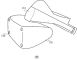
- FIG. 2 is an external view of the head mounted display 100 according to the embodiment.
- the head mounted display 100 includes a main body 110, a head contact portion 112, and a light emitting portion 114.
- the main body 110 is equipped with a display, a GPS unit for acquiring position information, an attitude sensor, a communication device, and the like.
- the head contact portion 112 may be provided with a biometric information acquisition sensor capable of measuring biometric information such as a player's body temperature, pulse, blood component, sweating, brain wave, and cerebral blood flow.
- the light emitting unit 114 emits light in a color instructed by the game device 10, and functions as a reference for calculating the position of the head mounted display 100 in the image captured by the image capturing device 14.
- the head-mounted display 100 may be further provided with a camera that captures the eyes of the player.
- the camera mounted on the head mounted display 100 can detect the line of sight of the player, the movement of the pupil, the blink, and the like.
- the display control technique of the present embodiment is not limited to the head mounted display 100 in a narrow sense, and may include glasses, glasses-type displays, glasses-type cameras, headphones, and headsets. (Headphones with microphone), earphones, earrings, ear-hook cameras, hats, hats with cameras, hair bands, etc. can also be applied.
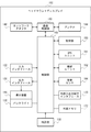
- FIG. 3 is a functional configuration diagram of the head mounted display 100.
- the head mounted display 100 includes an input interface 122, an output interface 130, a backlight 132, a communication control unit 140, a network adapter 142, an antenna 144, a storage unit 150, a GPS unit 161, a wireless unit 162, an attitude sensor 164, and external input / output terminals.
- An interface 170, an external memory 172, a clock unit 180, a display device 190, and a control unit 160 are provided.
- these components are realized by the CPU, memory, programs loaded in the memory, etc. of any computer.
- the functional blocks realized by their cooperation are depicted. Therefore, it will be understood by those skilled in the art that these functional blocks can be realized in various forms by only hardware, only software, or a combination thereof.
- the control unit 160 is a main processor that processes and outputs signals such as image signals and sensor signals, and commands and data.
- the input interface 122 receives an operation signal or a setting signal from an input button or the like and supplies it to the control unit 160.
- the output interface 130 receives the image signal from the control unit 160 and displays it on the display device 190.
- the backlight 132 supplies a backlight to the liquid crystal display that constitutes the display device 190.
- the communication control unit 140 transmits the data input from the control unit 160 to the outside by wired or wireless communication via the network adapter 142 or the antenna 144.
- the communication control unit 140 also receives data from the outside by wire or wireless communication via the network adapter 142 or the antenna 144, and outputs the data to the control unit 160.
- the storage unit 150 temporarily stores data, parameters, operation signals, etc. processed by the control unit 160.
- the GPS unit 161 receives position information from GPS satellites and supplies it to the control unit 160 according to an operation signal from the control unit 160.
- the wireless unit 162 receives the position information from the wireless base station and supplies it to the control unit 160 in accordance with the operation signal from the control unit 160.
- the attitude sensor 164 detects attitude information such as the orientation and inclination of the main body 110 of the head mounted display 100.
- the attitude sensor 164 is realized by appropriately combining a gyro sensor, an acceleration sensor, an angular acceleration sensor, and the like.
- the external input / output terminal interface 170 is an interface for connecting a peripheral device such as a USB (Universal Serial Bus) controller.
- the external memory 172 is an external memory such as a flash memory.
- the clock unit 180 sets time information by a setting signal from the control unit 160 and supplies the time data to the control unit 160.
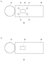
- FIG. 4 shows an external configuration of the input device 20.
- FIG. 4A shows the upper surface configuration of the input device 20, and
- FIG. 4B shows the lower surface configuration of the input device 20.
- the input device 20 includes a light emitter 22 and a handle 24.
- the light emitting body 22 is formed into a sphere on the outside with a resin having a light transmitting property, and has a light emitting element such as a light emitting diode or a light bulb inside. When the inner light emitting element emits light, the entire outer sphere glows.
- Operation buttons 30, 32, 34, 36, 38 are provided on the upper surface of the handle 24, and operation buttons 40 are provided on the lower surface.
- the player operates the operation buttons 30, 32, 34, 36, 38 with the thumb and the operation button 40 with the index finger while holding the end portion of the handle 24 with the hand.
- the operation buttons 30, 32, 34, 36, 38 are of a push-down type, and the player operates them by pushing them down.
- the operation button 40 may be capable of inputting an analog amount.
- FIG. 5 shows the internal configuration of the input device 20.
- the input device 20 includes a wireless communication module 48, a processing unit 50, a light emitting unit 62, and operation buttons 30, 32, 34, 36, 38, 40.
- the wireless communication module 48 has a function of transmitting and receiving data to and from the wireless communication module of the game device 10.
- the processing unit 50 executes intended processing in the input device 20.
- the processing unit 50 includes a main control unit 52, an input reception unit 54, a triaxial acceleration sensor 56, a triaxial gyro sensor 58, and a light emission control unit 60.
- the main control unit 52 transmits / receives necessary data to / from the wireless communication module 48.
- the input receiving unit 54 receives input information from the operation buttons 30, 32, 34, 36, 38, 40 and sends it to the main control unit 52.
- the triaxial acceleration sensor 56 detects acceleration components in the XYZ triaxial directions.
- the triaxial gyro sensor 58 detects angular velocities on the XZ plane, the ZY plane, and the YX plane.
- the width direction of the input device 20 is set as the X axis
- the height direction is set as the Y axis
- the longitudinal direction is set as the Z axis.
- the triaxial acceleration sensor 56 and the triaxial gyro sensor 58 are arranged in the handle 24 of the input device 20, and are preferably arranged near the center in the handle 24.
- the wireless communication module 48 transmits the information detected by the triaxial acceleration sensor 56 and the information detected by the triaxial gyro sensor 58 to the wireless communication module of the game apparatus 10 in a predetermined cycle together with the input information from the operation button. ..
- This transmission cycle is set to 11.25 ms, for example.
- the light emission control unit 60 controls the light emission of the light emitting unit 62.
- the light emitting unit 62 has a red LED 64a, a green LED 64b, and a blue LED 64c, and is capable of emitting light of a plurality of colors.
- the light emission control unit 60 adjusts the light emission of the red LED 64a, the green LED 64b, and the blue LED 64c to cause the light emitting unit 62 to emit a desired color.
- the wireless communication module 48 When the wireless communication module 48 receives the light emission instruction from the game device 10, the wireless communication module 48 supplies the light emission instruction to the main control unit 52, and the main control unit 52 supplies the light emission instruction to the light emission control unit 60.
- the light emission control unit 60 controls the light emission of the red LED 64a, the green LED 64b, and the blue LED 64c so that the light emitting unit 62 emits light in the color designated by the light emission instruction.
- the light emission control unit 60 may control lighting of each LED by PWM (pulse width modulation) control.
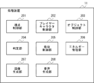
- FIG. 6 is a functional configuration diagram of the game device 10.
- the processing device 11 of the game device 10 includes a viewpoint control unit 201, a player character control unit 202, an object control unit 203, a determination unit 204, an absorption control unit 205, an energy management unit 206, an image generation unit 207, and a sound generation unit 208.
- Prepare These functional blocks can also be realized in various forms by only hardware, only software, or a combination thereof.
- the viewpoint control unit 201 controls the position of the viewpoint for generating an image of the game world.
- the viewpoint control unit 201 sets a viewpoint near the eyes of the player character and moves the position of the viewpoint as the player character moves.
- the viewpoint position is automatically set at a predetermined speed along a predetermined route in the game world. To move.
- the viewpoint control unit 201 may change the position of the viewpoint or the moving speed according to a player's instruction or a game situation, as long as it is within a predetermined range (for example, a range of a radius of several meters to several tens of meters). Good.
- a predetermined range for example, a range of a radius of several meters to several tens of meters.
- the position of the viewpoint or the moving speed may be changed within a predetermined range according to an instruction input to the input device 20 or the movement or posture of the input device 20 or the head mounted display 100.
- the movable range may be changed according to the position in the game world, the terrain, and the like. For example, the movable range may be widened in a vast grassland, or the movable range may be completely eliminated in a cave or a narrow road so that the movable range can be set only on a predetermined route.
- the viewpoint control unit 201 when the line of sight of the player character is directed toward the game object for a predetermined time or more, that is, a target such as an object or a character arranged in the game world is near the center of the display screen for a predetermined time (for example, When held for 2 to 3 seconds (also referred to as “focus”), the viewpoint position may be moved toward the target. It may be determined that the target is focused when the target is held near the center of the display screen for a predetermined time and the player extends one or both hands toward the target. In addition, the viewpoint position may stay near the target when the player character is within a predetermined range from the target or when the player character is touching the target.
- the viewpoint control unit 201 may change the viewpoint position according to an instruction from the player.
- the viewpoint position may be changed according to an instruction input to the input device 20 or the movement or posture of the input device 20 or the head mounted display 100.
- the player character control unit 202 controls the player character expressing at least a part of the player's body.
- the player character's hand and arm are moved in accordance with the movement of the input device 20.
- the player character control unit 202 may move the player character's hand and arm in accordance with the movement of a controller including a plurality of operation buttons, instead of the input device 20, or the player's hand imaged by the imaging device 14.
- the player character's hand and arm may be moved according to the movement of the arm.
- the player character control unit 202 may obtain the player's movement by capturing an image of the player wearing a suit with a marker or the like by the image capturing device 14 and analyzing the movement of the marker.
- the player may be imaged by the imaging device 14 without using the above, and the movement of the player may be acquired by any known motion capture technique.
- the head of the player character may be moved according to the movement of the head mounted display 100, or the imaging device 14 may be used. The whole body of the player character may be moved according to the movement of the body of the player who is imaged.
- the player character control unit 202 determines the display mode of the player character according to the consciousness level, the relaxation level, etc. of the player.
- the player's level of consciousness, relaxation level, etc. are stored in the energy value acquired by the player during the game, the observed values of the player's heart rate, blood pressure, body temperature, brain waves, etc., and information obtained by analyzing the captured image of the player. It may be determined based on.
- the object control unit 203 controls objects arranged in the game world.
- Objects include interactive objects that can interact with the player character and non-interactive objects that do not interact with the player character.
- An interactive object can give energy to the player character when it comes into contact with the player character. Including with non-energy objects.
- the energy object may have a shape of, for example, an animal, a plant, a crystal of quartz, or may have any shape of a sphere, a cube, a rectangular parallelepiped, a spheroid, a cone, a frustum, or the like. Good.
- the object control unit 203 automatically moves a movable object such as an animal.
- the object control unit 203 controls an object such as a plant to be shaken by the wind.
- the object control unit 203 controls an object existing in water so that the object rides on the water stream and sways.
- the object control unit 203 controls a plurality of particles forming an object so that the particles fluctuate. As a result, the mental state of the player can be relaxed.
- the object control unit 203 may move the target object toward the player character when the player focuses on the object for a predetermined time. As a result, the player can bring the object closer to and touch or resonate by gazing at the object of interest.
- the object control unit 203 determines the movement and display mode of particles that form the object according to the time the object is held near the center of the display screen, the held position, and the like. May be changed. For example, the longer an object is held near the center of the display screen, and the closer the position of the object is held to the center of the display screen is, the particles that make up the object are aggregated or displayed in a dark color. By doing so, the shape of the object may be made clear.
- the particles that make up the object are gradually diffused or displayed in a light color, so that the object melts into the space. May be given.
- the player's attention can be effectively directed to the object.
- the player is interested in surrounding objects and characters during the game play and repeats the training of paying attention to them, so that the player's concentration and attention can be improved.
- the determination unit 204 determines whether or not the player character has come into contact with the object.
- the determination unit 204 may determine that the player character has come into contact with the object when the distance between the outer surface of the player character's body and the outer surface of the object is less than a predetermined value.
- the absorption control unit 205 causes the player character to perform an action indicating that the plurality of particles included in the object that has contacted the player character is absorbed by the player character. ..
- the absorption control unit 205 may determine the action to be executed according to the type of the object with which the player character contacts. For example, when a player character comes into contact with an energetic body such as a crystal, the energetic body is thrown away by the player character or is deformed by being pushed by the player character, and then particles inside the energetic body jump out and May perform an action of moving toward the player character.
- the absorption control unit 205 exchanges the particles existing in the vicinity of the surface after the player character and the animal, the plant, etc. pass through each other and resonate with each other. You may make it perform the action mutually absorbed.
- the absorption control unit 205 may cause the sound generation unit 208 to generate and output a sound such as a binaural beat or a crystal bowl which is said to have an action of changing the brain wave.
- the player can be guided to a relaxed brain wave state, and a more comfortable feeling can be given to the player.
- the energy management unit 206 manages the amount of particles absorbed by the player character from the object as the energy acquired by the player.
- the energy management unit 206 adds energy even when the player character comes into contact with particles floating in the game world.
- the energy management unit 206 adds energy when it resonates with an object such as an animal or a plant.
- the energy management unit 206 acquires information indicating the quality of the situation in the real world from the game server 3 or the like and displays it on the game screen. When the energy acquired by the player reaches a predetermined value, the energy management unit 206 reverses the information indicating the situation in the real world. As a result, the player can enjoy not only improving the mental state of the player but also purifying the real world through the game.
- the image generation unit 207 renders a virtual three-dimensional space by using the viewpoint position set by the viewpoint control unit 201 and the line-of-sight direction set in accordance with the orientation of the head mounted display 100, thereby rendering an image of the game world. To generate.
- the image generation unit 207 changes the line-of-sight direction for generating an image in the virtual three-dimensional space according to the orientation of the head mounted display 100.
- the voice generation unit 208 generates a voice in the game world.
- the sound generation unit 208 sets a sound source to an object or particle arranged in the game world, generates a unique sound corresponding to the type of the object or particle from the sound source, and generates a sound in the game world.
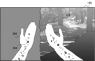
- FIG. 7 shows an example of a game screen displayed on the display device 190 of the head mounted display 100.
- a rendered image of the game world, the hand of the player character 300, and a tree 310 that is an object placed in the game world are displayed.
- Particles 303 are displayed inside the hand of the player character 300.
- the player character control unit 202 moves the position of the hand of the player character 300 according to the movement of the input device 20.
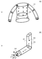
- FIG. 8 shows an example of objects arranged in the game world.
- the tree 310 shown in FIG. 8A is composed of a large number of light particles 312, as shown in an enlarged view in FIG. 8B.
- the object control unit 203 rocks the particles 312 that form the tree 310.
- FIG. 9 shows an example of player characters arranged in the game world.
- the shape of the player character 300 is defined by the model 301 imitating the body of the player.
- the player character 300 includes a thin gaseous base body 302 serving as a base, which is arranged in the model 301, and a large number of lights moving in and around the base body 302. It is represented by particles 303.
- a locator 304 for designating an arrangement position and a movement destination of the particles 303 is arranged.
- the player character control unit 202 slowly rocks the base body 302 on the spot, and causes the particles 303 to move back and forth inside the model 301.
- the player character control unit 202 gradually changes the display mode of the player character 300 according to the consciousness level of the player, and also changes the display mode in real time according to the player's relaxation level, actions such as breathing and purification.
- the player character control unit 202 changes the size and color of the base body 302 according to the relaxation level of the player. For example, as the player's relaxation level is higher, the base body 302 is made larger and changed to a color close to white.
- the player character control unit 202 changes the moving speed of the particles 303 according to the relaxation level of the player. For example, the higher the player's relaxation level, the slower the moving speed of the particles 303. This allows the player's relaxation level to be shown in a visually easy-to-understand manner.
- the player character control unit 202 determines the length of the lower body of the base body 302, the amount of particles 303 generated from the lower body, the intensity or color of light surrounding the base body 302, the intensity of light, or the intensity of light depending on the level of consciousness of the player. The speed at which the color changes, the type of color, etc. are changed. As a result, the player can easily objectively observe his / her own consciousness level, and when the player character of the other player is displayed on the game screen, the consciousness level of the other player can be easily grasped. You can
- the player character control unit 202 displays a state in which the player character 300 puts his / her hand on the chest while the player holds the input device 20 around his / her chest, and increases the moving speed of the particles 303, By making the light of 303 strong and changing the sound when the particles 303 flow in the body of the player character 300, the body of the player character 300 is purified, and a feeling full of energy is produced. At this time, the energy management unit 206 increases the energy of the player.
- the player character control unit 202 analyzes the image of the player captured by the image capturing device 14, and grasps the breathing motion of the player from the vertical movement of the player's shoulders and the front-back movement of the chest. While the player is inhaling, the player character control unit 202 causes particles to appear in front of the face of the player character 300 and move toward the mouth of the player character 300, as shown in FIG. Further, as shown in FIG. 10B, the model 301 of the player character 300 is inflated. At this time, as shown in FIG. 10C, since the particles 303 in the model 301 are dispersed, the density becomes low.
- the player character control unit 202 moves the particles 320 remaining in front of the face of the player character 300 away from the mouth, as shown in FIG. Further, as shown in FIG. 11B, the model 301 of the player character 300 is contracted. At this time, as shown in FIG. 11C, since the particles 303 in the model 301 aggregate, the density becomes high and the shape of the model 301 becomes clear. In this way, the player can be made aware of breathing by visualizing the action of breathing.
- FIG. 12 is a diagram for explaining the interaction between the player character and the object or particle.
- the absorption control unit 205 moves the particles 330 within the first range 331 around the player character 300 toward the player character 300.
- the first range 331 is set around the player character 300 and has a capsule-like shape. The collision determination between the first range 331 and the particles 330 and the movement to the player character 300 are not executed for the object.
- the determination unit 204 determines whether or not the particles 330 or objects arranged in the game world have come into contact with the boundary of the second range 332 around the player character 300.
- the second range 332 is narrower than the first range 331 and has a shape similar to the model of the player character 300.
- the absorption control unit 205 changes the display mode of the particle 330 or the object to a display mode indicating that the particle 330 or the object is in contact with the player character. For example, the absorption control unit 205 causes the particle 330 or the object to glow with a color according to the type of the particle 330 or the object.
- the absorption control unit 205 sets a sound source for the particles 330 within the second range 332, and causes the sound source to emit a sound according to the type of the particles 330 or the object.
- the sound source may be set to the particles 330 that are within the fourth range different from the second range 332.
- the absorption control unit 205 moves the particles 330 so as not to enter the third range 333 in front of the eyes of the player character. For example, the absorption control unit 205 moves the particles 330 that are in contact with the boundary of the third range 333 along the boundary of the third range 333. As a result, it is possible to prevent the image in which the particles hit the eyes of the player who is watching the game screen using the head mounted display 100 from being displayed.
- FIG. 13 shows an example of absorption action when particles are absorbed by the player character.
- the absorption control unit 205 keeps the vector when the particles 330 move within the second range 332, as shown in FIG. It is made to enter the body of the character 300, gradually thinned to be transparent, and erased after a predetermined time.
- the absorption control unit 205 rotates the particles 330 around the hand for a predetermined time as shown in FIG. 13D. After that, as shown in FIG.
- the player character 300 is moved to the vicinity of the shoulder and further moved toward the center of the chest to be gradually thinned to be transparent and erased after a predetermined time.
- the energy management unit 206 adds the number of particles 330 absorbed by the player character 300 as the acquired energy.
- FIG. 14 shows another example of absorption action when particles are absorbed by the player character.
- the absorption control unit 205 rotates around the hand of the player character 300 as shown in FIG. 14C. While gradually decreasing the rotation speed of the particles 330, the radius of rotation is reduced to bring the particles closer to the hand, as shown in FIG. 14D, the particles are absorbed into the chest via the arms and the shoulders.
- the absorption control unit 205 may cause the particles 330 absorbed in the body of the player character 300 to exist inside the player character 300 together with the particles 303 included in the player character 300.
- the absorbed particles 330 may be displayed in a display mode different from that of the particles 303 forming the body of the player character 300.
- the image generation unit 207 does not limit the number of particles to a predetermined value. A number (for example, 10) of particles is displayed together in one particle.
- the image generation unit 207 may display the collected particles in a display mode different from that of the original particles. For example, the particle size, shape, display color, transparency, etc. may be changed.
- the image generating unit 207 collects a predetermined number of particles into one particle so that the total number of displayed particles is a predetermined number (for example, 100). If the number of particles is less than the number of particles, the total number of particles displayed may be set to a predetermined number or more by controlling the number of particles displayed collectively.
- the sound generation unit 208 combines sound sources of a predetermined number of particles into one sound source to generate sound. This makes it possible to reduce the processing load while maintaining the effect of video and audio.
- the absorption control unit 205 causes the sound generation unit 208 to generate a sound effect and a breathing sound peculiar to the object while the boundary of the second range 332 of the player character 300 touches the object, and the player touches the object through the hand.
- the character 300 is moved so that particles flow into the body of the character 300.
- the energy management unit 206 reduces the energy amount of the object while the player character 300 is absorbing energy from the object.
- the absorption control unit 205 suspends energy absorption.
- the absorption control unit 205 ends the energy absorption when the energy amount of the object becomes 0. The object whose energy amount becomes 0 cannot absorb the energy even if the player character 300 touches it again.
- the amount of energy that the object has is predetermined as a unique parameter, and basically, the player cannot absorb energy above this value from the object.
- the player can absorb more energy than the amount of energy peculiar to the object.
- the absorption control unit 205 causes the sound generation unit 208 to generate the breathing sound of the object.
- the energy management unit 206 increases the amount of energy that the object can emit. As a result, the player can be made more aware of the breathing action, and the improvement of the mental state and the health state by the correct breathing method can be promoted.
- FIG. 15 shows an example of an absorbing action when particles constituting an object are absorbed by a player character.
- an animal such as an elephant 314 arranged in the game world is also composed of a plurality of particles.
- the absorption control unit 205 causes the particle 315 forming the elephant 314 of the player character 300 to reach the elephant 314 as shown in FIG. 15C.
- the particles 315 forming the surface of the elephant 314 and the particles 303 forming the hand of the player character 300 may have different appearances. For example, as shown in FIG.
- the particles 315 forming the elephant 314 and the particles 303 forming the player character 300 may have different particle sizes, shapes, display colors, and transparency.
- the absorption control unit 205 moves the particles 316 absorbed in the body of the player character 300 toward the chest from the hand of the player character 300 via the arm. This can give the player a feeling that the energy absorbed from the elephant 314 permeates into the player's body.
- the absorption control unit 205 may move the particles 315 absorbed in the body of the player character 300 and change the appearance to the same as the particles 303 that form the player character 300. As a result, the player can feel as if the energy absorbed from the elephant 314 was converted into the player's own energy.
- the particles 315 forming the elephant 314 and the particles 303 forming the player character 300 may have the same or similar appearance. As a result, it is possible to express a world view in which all things existing in the game world are composed of the same or similar particles, and energy can be exchanged with each other. In addition, it is possible to give the player a feeling that the energy absorbed from the elephant 314 is accumulated in the player's body.
- FIG. 16 shows another example of interaction between the player character and particles.
- energy management is performed.
- the unit 206 displays energy particles 330 between both hands, and gradually increases the number of particles 330.
- the energy management unit 206 changes the display mode of the particles 330 and indicates to the player that a new object can be created, as shown in FIG.
- the energy management unit 206 changes the shape of the particle group displayed between the hands of the player character 300, as shown in FIG.
- the object 340 is formed and moved around the player character 300. As a result, the player can be motivated to accumulate a lot of energy.
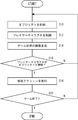
- FIG. 17 is a flowchart showing the procedure of the game control method according to the embodiment.
- the object control unit 203 controls an object that is arranged in the virtual three-dimensional space and includes a plurality of particles (S10), and the player character control unit 202 is a player that is arranged in the virtual three-dimensional space and can be operated by the player.
- the character is controlled (S12), and the image generation unit 207 generates an image of the virtual three-dimensional space (S14).
- the determination unit 204 determines whether or not the player character has come into contact with the object (S16). If there is no contact (N in S16), the process returns to S10.
- the absorption control unit 205 causes the player character to perform an action indicating that the plurality of particles included in the object in contact with the player character are absorbed by the player character (S18). If the game is not ended (N of S20), the process returns to S10, and if the game is ended (Y of S20), the process is ended.
- the present invention can be used for a display control device that controls display on a display device.
- 1 game system 3 game server, 10 game device, 11 processing device, 12 output control device, 13 storage device, 14 imaging device, 15 output device, 20 input device, 100 head mounted display, 201 viewpoint control unit, 202 player character Control unit, 203 object control unit, 204 determination unit, 205 absorption control unit, 206 energy management unit, 207 image generation unit, 208 sound generation unit.
Landscapes
- Engineering & Computer Science (AREA)
- Multimedia (AREA)
- Physics & Mathematics (AREA)
- General Physics & Mathematics (AREA)
- Theoretical Computer Science (AREA)
- Human Computer Interaction (AREA)
- Optics & Photonics (AREA)
- General Engineering & Computer Science (AREA)
- Acoustics & Sound (AREA)
- Computer Graphics (AREA)
- Computer Hardware Design (AREA)
- Software Systems (AREA)
- User Interface Of Digital Computer (AREA)
- Processing Or Creating Images (AREA)
Abstract
表示制御装置の一例であるゲーム装置は、仮想三次元空間の画像を生成する画像生成部207と、仮想三次元空間に配置された、複数の粒子を含むオブジェクトを制御するオブジェクト制御部203と、仮想三次元空間に配置された、プレイヤーが操作可能なプレイヤーキャラクタを制御するプレイヤーキャラクタ制御部202と、プレイヤーキャラクタとオブジェクトとが接触したか否かを判定する判定部204と、判定部204によりプレイヤーキャラクタとオブジェクトとが接触したと判定された場合、プレイヤーキャラクタと接触したオブジェクトに含まれる複数の粒子がプレイヤーキャラクタに吸収される様子を表すアクションを実行させる吸収制御部205とを備える。
Description
本発明は、表示制御技術に関し、とくに、表示装置への表示を制御する表示制御プログラム、表示制御装置、及び表示制御方法に関する。
ゲーム機に接続されたヘッドマウントディスプレイを頭部に装着して、ヘッドマウントディスプレイに表示された画面を見ながら、コントローラなどを操作してプレイすることが可能なゲームが人気を博している。ヘッドマウントディスプレイを使用することにより、映像世界への没入感が高まり、ゲームのエンタテインメント性を一層高める効果がある。
本発明者は、このような没入感の高い映像世界を利用して、視聴者の精神状態を向上させることができると考え、本発明に想到した。すなわち、本発明の目的は、視聴者に心地良い感覚を与えることが可能な表示技術を提供することにある。
上記課題を解決するために、本発明のある態様の表示制御プログラムは、コンピュータに、仮想三次元空間の画像を生成する画像生成部と、仮想三次元空間に配置された、複数の粒子を含むオブジェクトを制御するオブジェクト制御部と、仮想三次元空間に配置された、プレイヤーが操作可能なプレイヤーキャラクタを制御するプレイヤーキャラクタ制御部と、プレイヤーキャラクタとオブジェクトとが接触したか否かを判定する判定部と、判定部によりプレイヤーキャラクタとオブジェクトとが接触したと判定された場合、プレイヤーキャラクタと接触したオブジェクトに含まれる複数の粒子がプレイヤーキャラクタに吸収される様子を表すアクションを実行させる吸収制御部と、を実現させる。
本発明の別の態様は、表示制御装置である。この装置は、仮想三次元空間の画像を生成する画像生成部と、仮想三次元空間に配置された、複数の粒子を含むオブジェクトを制御するオブジェクト制御部と、仮想三次元空間に配置された、プレイヤーが操作可能なプレイヤーキャラクタを制御するプレイヤーキャラクタ制御部と、プレイヤーキャラクタとオブジェクトとが接触したか否かを判定する判定部と、判定部によりプレイヤーキャラクタとオブジェクトとが接触したと判定された場合、プレイヤーキャラクタと接触したオブジェクトに含まれる複数の粒子がプレイヤーキャラクタに吸収される様子を表すアクションを実行させる吸収制御部と、を備える。
本発明のさらに別の態様は、表示制御方法である。この方法は、コンピュータに、仮想三次元空間の画像を生成するステップと、仮想三次元空間に配置された、複数の粒子を含むオブジェクトを制御するステップと、仮想三次元空間に配置された、プレイヤーが操作可能なプレイヤーキャラクタを制御するステップと、プレイヤーキャラクタとオブジェクトとが接触したか否かを判定するステップと、プレイヤーキャラクタとオブジェクトとが接触したと判定された場合、プレイヤーキャラクタと接触したオブジェクトに含まれる複数の粒子がプレイヤーキャラクタに吸収される様子を表すアクションを実行させるステップと、をコンピュータに実行させる。
なお、以上の構成要素の任意の組合せ、本発明の表現をシステム、コンピュータプログラム、コンピュータプログラムを読み取り可能に記録した記録媒体、データ構造などの間で変換したものもまた、本発明の態様として有効である。
本発明によれば、視聴者に心地良い感覚を与えることが可能な表示技術を提供することができる。
実施の形態に係るゲーム装置は、表示制御装置の一例であり、仮想三次元空間にオブジェクトやキャラクタなどが配置されたゲーム世界の画像を生成して表示する。このゲーム世界において、動物や植物などのオブジェクトや、プレイヤーの体を表現したプレイヤーキャラクタは、複数の光の粒子により構成されており、幻想的な心象世界を表現したゲーム世界の映像表現がプレイヤーに提供される。この映像表現は、全ての物質が素粒子から構成されていることと対応しており、ゲーム世界において粒子がエネルギーの源であるようなイメージをプレイヤーに想起させる。プレイヤーがプレイヤーキャラクタを操作して、ゲーム世界に配置されたオブジェクトに触れると、ゲーム装置は、オブジェクトを構成する粒子が光り輝きながらプレイヤーキャラクタに吸い込まれる様子を表示する。プレイヤーは、ゲーム世界において動物や植物などに触れ、互いに共鳴し合い、エネルギーを吸収するといった、斬新で心地良い癒しの感覚を体験することができる。これにより、プレイヤーは、ゲームを通じて精神状態を向上させることができる。
このような映像表現は、据え置き型の表示装置や携帯型の表示装置などに表示されてもよいが、ヘッドマウントディスプレイ(HMD)を使用した方がより効果的である。この場合、ゲーム装置は、プレイヤーキャラクタの目の位置に視点位置を設定し、ヘッドマウントディスプレイの向きに合わせて視線方向を変化させながら、オブジェクトが配置された仮想三次元空間をレンダリングし、生成した一人称視点の画像をヘッドマウントディスプレイに表示する。これにより、プレイヤーは、自身が幻想的な心象世界の中に現実に存在しているかのような深い没入感を得ることができる。また、より現実感の高い映像表現の中で、斬新で心地良い癒しの感覚を体験することができるので、より効果的に精神状態を高めることができる。
図1は、実施の形態に係るゲームシステム1の構成例を示す。ゲームシステム1は、ゲーム装置10と、ヘッドマウントディスプレイ100と、プレイヤーが把持して操作する入力装置20a及び20b(「入力装置20」と総称する)と、ヘッドマウントディスプレイ100を装着したプレイヤーを撮影する撮像装置14と、画像を表示する出力装置15とを備える。出力装置15はテレビであってよい。ゲーム装置10は、アクセスポイント(AP)などを介して、インターネットなどの外部のネットワークに接続される。
本実施の形態のゲーム装置10は、複数のゲーム装置10のプレイヤーがゲーム世界を共有して同時にゲームを実行することを可能とするために設けられたゲームサーバ3に接続される。ゲームサーバ3は、ゲームに参加しているゲーム装置10のそれぞれからプレイヤーキャラクタの位置などの情報を取得し、取得した情報をそれぞれのゲーム装置10に配信する。
ヘッドマウントディスプレイ100は、プレイヤーの頭部に装着されて、仮想現実(VR)の映像世界をプレイヤーに提供する。ヘッドマウントディスプレイ100にヘッドトラッキング機能をもたせ、プレイヤーの頭部の動きに連動して表示画像を更新することで、映像世界への没入感を高められる。
ゲーム装置10は、処理装置11、出力制御装置12、及び記憶装置13を備える。処理装置11は、プレイヤーにより入力装置20に入力された操作情報や、入力装置20及びヘッドマウントディスプレイ100の位置情報や姿勢情報などを受け付けて、ゲームアプリケーションを実行する。処理装置11と入力装置20とはケーブルで接続されてよく、また既知の無線通信プロトコルで接続されてもよい。出力制御装置12は、処理装置11で生成された画像データをヘッドマウントディスプレイ100に出力する処理ユニットであり、出力制御装置12とヘッドマウントディスプレイ100とはケーブルで接続されてよく、また既知の無線通信プロトコルで接続されてもよい。記憶装置13は、ゲームアプリケーションのプログラムデータ、ゲームアプリケーションにより使用される仮想三次元空間の形状データ、配置されるオブジェクトやキャラクタの形状データなどを記憶する。
撮像装置14はステレオカメラであって、ヘッドマウントディスプレイ100を装着したプレイヤーを所定の周期で撮影し、撮影画像を処理装置11に供給する。後述するが、ヘッドマウントディスプレイ100にはプレイヤーの頭部をトラッキングするためのマーカ(トラッキング用LED)が設けられ、処理装置11は、撮影画像に含まれるマーカの位置に基づいてヘッドマウントディスプレイ100の動きを検出する。ヘッドマウントディスプレイ100には姿勢センサ(加速度センサ及びジャイロセンサ)が搭載され、処理装置11は、姿勢センサで検出されたセンサデータをヘッドマウントディスプレイ100から取得することで、マーカの撮影画像の利用とあわせて、高精度のトラッキング処理を実施する。なお、トラッキング処理については従来より様々な手法が提案されており、処理装置11は、ヘッドマウントディスプレイ100の動きを検出できるものであれば、どのようなトラッキング手法を採用してもよい。
また、後述するが、入力装置20には、現実空間における入力装置20の姿勢(例えば、位置及び向き)を検出するためのマーカ(発光部)が設けられ、処理装置11は、撮影画像に含まれるマーカの位置・態様に基づいて入力装置20の位置及び向きを検出する。変形例として、入力装置20には、姿勢センサ(例えば、加速度センサ及びジャイロセンサ)が搭載されてもよい。処理装置11は、姿勢センサで検出されたセンサデータを入力装置20から取得し、マーカの撮影画像の利用に代えて、または、マーカの撮影画像の利用とあわせて、入力装置20の存在位置及び向きを検出してもよい。なお、入力装置20の位置及び向きを検出できるものであれば、他の公知の手法を採用してもよい。
プレイヤーは、ヘッドマウントディスプレイ100を使用して画像を見るので、出力装置15は必ずしも必要ではないが、出力装置15を用意することで、別の視聴者が画像を見ることができる。出力制御装置12又は処理装置11は、ヘッドマウントディスプレイ100を装着したプレイヤーが見ている画像と同じ画像を出力装置15に表示させてもよいが、別の画像を表示させてもよい。例えば、ヘッドマウントディスプレイ100を装着したプレイヤーと別の視聴者とが一緒にゲームをプレイするような場合、出力装置15には、当該別の視聴者のキャラクタ視点からのゲーム画像が表示されてもよい。
ヘッドマウントディスプレイ100は、プレイヤーが頭部に装着することによりその眼前に位置する表示パネルに画像を表示する表示装置である。ヘッドマウントディスプレイ100は、左目用表示パネルに左目用の画像を、右目用表示パネルに右目用の画像を、それぞれ別個に表示する。これらの画像は左右の視点から見た視差画像を構成し、立体視を実現する。なおプレイヤーは光学レンズを通して表示パネルを見るため、ゲーム装置10は、レンズによる光学歪みを補正した視差画像データをヘッドマウントディスプレイ100に供給する。この光学歪みの補正処理は、処理装置11、出力制御装置12のいずれが行ってもよい。
なお出力制御装置12による機能は、処理装置11に組み込まれてもよい。つまりゲーム装置10の処理ユニットは、1台の処理装置11から構成されても、また処理装置11および出力制御装置12から構成されてもよい。以下においては、VR画像をヘッドマウントディスプレイ100に提供する機能を、まとめてゲーム装置10の機能として説明する。
図2は、実施の形態に係るヘッドマウントディスプレイ100の外観図である。ヘッドマウントディスプレイ100は、本体部110、頭部接触部112、及び発光部114を備える。
本体部110には、ディスプレイ、位置情報を取得するためのGPSユニット、姿勢センサ、通信装置などが備えられる。頭部接触部112には、プレイヤーの体温、脈拍、血液成分、発汗、脳波、脳血流などの生体情報を計測することのできる生体情報取得センサが備えられてもよい。発光部114は、ゲーム装置10から指示された色で発光し、撮像装置14により撮像される画像においてヘッドマウントディスプレイ100の位置を算出するための基準として機能する。
ヘッドマウントディスプレイ100には、さらに、プレイヤーの目を撮影するカメラが設けられてもよい。ヘッドマウントディスプレイ100に搭載されたカメラにより、プレイヤーの視線、瞳孔の動き、瞬きなどを検出することができる。
本実施の形態においては、ヘッドマウントディスプレイ100について説明するが、本実施の形態の表示制御技術は、狭義のヘッドマウントディスプレイ100に限らず、めがね、めがね型ディスプレイ、めがね型カメラ、ヘッドフォン、ヘッドセット(マイクつきヘッドフォン)、イヤホン、イヤリング、耳かけカメラ、帽子、カメラつき帽子、ヘアバンドなどを装着した場合にも適用することができる。
図3は、ヘッドマウントディスプレイ100の機能構成図である。ヘッドマウントディスプレイ100は、入力インタフェース122、出力インタフェース130、バックライト132、通信制御部140、ネットワークアダプタ142、アンテナ144、記憶部150、GPSユニット161、無線ユニット162、姿勢センサ164、外部入出力端子インタフェース170、外部メモリ172、時計部180、表示装置190、及び制御部160を備える。
これらの構成は、ハードウエアコンポーネントでいえば、任意のコンピュータのCPU、メモリ、メモリにロードされたプログラムなどによって実現されるが、ここではそれらの連携によって実現される機能ブロックを描いている。したがって、これらの機能ブロックがハードウエアのみ、ソフトウエアのみ、又はそれらの組合せによっていろいろな形で実現できることは、当業者には理解されるところである。
制御部160は、画像信号、センサ信号などの信号や、命令やデータを処理して出力するメインプロセッサである。入力インタフェース122は、入力ボタンなどから操作信号や設定信号を受け付け、制御部160に供給する。出力インタフェース130は、制御部160から画像信号を受け取り、表示装置190に表示させる。バックライト132は、表示装置190を構成する液晶ディスプレイにバックライトを供給する。
通信制御部140は、ネットワークアダプタ142又はアンテナ144を介して、有線又は無線通信により、制御部160から入力されるデータを外部に送信する。通信制御部140は、また、ネットワークアダプタ142またはアンテナ144を介して、有線又は無線通信により、外部からデータを受信し、制御部160に出力する。
記憶部150は、制御部160が処理するデータやパラメータ、操作信号などを一時的に記憶する。
GPSユニット161は、制御部160からの操作信号にしたがって、GPS衛星から位置情報を受信して制御部160に供給する。無線ユニット162は、制御部160からの操作信号にしたがって、無線基地局から位置情報を受信して制御部160に供給する。
姿勢センサ164は、ヘッドマウントディスプレイ100の本体部110の向きや傾きなどの姿勢情報を検出する。姿勢センサ164は、ジャイロセンサ、加速度センサ、角加速度センサなどを適宜組み合わせて実現される。
外部入出力端子インタフェース170は、USB(Universal Serial Bus)コントローラなどの周辺機器を接続するためのインタフェースである。外部メモリ172は、フラッシュメモリなどの外部メモリである。
時計部180は、制御部160からの設定信号によって時間情報を設定し、時間データを制御部160に供給する。
図4は、入力装置20の外観構成を示す。図4(a)は、入力装置20の上面構成を示し、図4(b)は、入力装置20の下面構成を示す。入力装置20は、発光体22及びハンドル24を有する。発光体22は、その外側を光透過性を有する樹脂で球体に形成され、内側に発光ダイオードや電球などの発光素子を有する。内側の発光素子が発光すると、外側の球体全体が光る。ハンドル24の上面には、操作ボタン30、32、34、36、38が設けられ、下面には操作ボタン40が設けられる。プレイヤーはハンドル24の端部を手で把持した状態で、操作ボタン30、32、34、36、38を親指で操作し、操作ボタン40を人差し指で操作する。操作ボタン30、32、34、36、38は、押下式に構成され、プレイヤーは押下することで操作する。操作ボタン40は、アナログ量を入力できるものであってよい。
図5は、入力装置20の内部構成を示す。入力装置20は、無線通信モジュール48、処理部50、発光部62、及び操作ボタン30、32、34、36、38、40を備える。無線通信モジュール48は、ゲーム装置10の無線通信モジュールとの間でデータを送受信する機能をもつ。処理部50は、入力装置20における所期の処理を実行する。
処理部50は、メイン制御部52、入力受付部54、3軸加速度センサ56、3軸ジャイロセンサ58、及び発光制御部60を有する。メイン制御部52は、無線通信モジュール48との間で必要なデータの送受を行う。
入力受付部54は、操作ボタン30、32、34、36、38、40からの入力情報を受け付け、メイン制御部52に送る。3軸加速度センサ56は、XYZの3軸方向の加速度成分を検出する。3軸ジャイロセンサ58は、XZ平面、ZY平面、YX平面における角速度を検出する。なお、ここでは、入力装置20の幅方向をX軸、高さ方向をY軸、長手方向をZ軸と設定する。3軸加速度センサ56および3軸ジャイロセンサ58は、入力装置20のハンドル24内に配置され、ハンドル24内の中心近傍に配置されることが好ましい。無線通信モジュール48は、操作ボタンからの入力情報とともに、3軸加速度センサ56による検出値情報、及び3軸ジャイロセンサ58による検出値情報を、所定の周期でゲーム装置10の無線通信モジュールに送信する。この送信周期は、たとえば11.25m秒に設定される。
発光制御部60は、発光部62の発光を制御する。発光部62は、赤色LED64a、緑色LED64b、青色LED64cを有し、複数色の発光を可能とする。発光制御部60は、赤色LED64a、緑色LED64b、青色LED64cの発光を調整して、発光部62を所望の色に発光させる。
無線通信モジュール48はゲーム装置10から発光指示を受け取ると、メイン制御部52に供給し、メイン制御部52は、発光制御部60に発光指示を供給する。発光制御部60は、発光部62が発光指示により指定された色で発光するように、赤色LED64a、緑色LED64b、青色LED64cの発光を制御する。たとえば発光制御部60は、各LEDをPWM(パルス幅変調)制御で点灯制御してもよい。
図6は、ゲーム装置10の機能構成図である。ゲーム装置10の処理装置11は、視点制御部201、プレイヤーキャラクタ制御部202、オブジェクト制御部203、判定部204、吸収制御部205、エネルギー管理部206、画像生成部207、及び音声生成部208を備える。これらの機能ブロックも、ハードウエアのみ、ソフトウエアのみ、又はそれらの組合せによっていろいろな形で実現できる。
視点制御部201は、ゲーム世界の画像を生成するための視点の位置を制御する。視点制御部201は、プレイヤーキャラクタの目の近傍に視点を設定し、プレイヤーキャラクタの移動に伴って視点の位置を移動させる。本実施の形態では、一人称視点の画像を生成するので、プレイヤーキャラクタの移動と視点位置の移動はほぼ同義である。本実施の形態では、リラックスした状態でゲーム世界を浮遊しているような感覚をプレイヤーに与えるために、ゲーム世界において予め定められた経路に沿って、定められた速度で視点位置を自動的に移動させる。視点制御部201は、定められた範囲(例えば、半径数m~数十mの範囲)内であれば、プレイヤーの指示やゲームの状況などに応じて視点の位置や移動速度を変更してもよい。例えば、入力装置20に対する指示入力や、入力装置20又はヘッドマウントディスプレイ100の動きや姿勢などに応じて、定められた範囲内で視点の位置や移動速度を変更してもよい。移動可能な範囲は、ゲーム世界における位置や地形などに応じて変化されてもよい。例えば、広大な草原においては移動可能な範囲を広くしてもよいし、洞窟内や狭い道などにおいては移動可能な範囲を全くなくし、予め定められた経路上しか移動できないようにしてもよい。
視点制御部201は、プレイヤーキャラクタの視線が所定時間以上ゲームオブジェクトの方に向いているとき、すなわち、ゲーム世界に配置されたオブジェクトやキャラクタなどのターゲットが表示画面の中心付近に所定時間(例えば、2~3秒)保持されたとき(これを「フォーカス」ともいう)に、そのターゲットの方に視点位置を移動させてもよい。ターゲットが表示画面の中心付近に所定時間保持され、かつ、プレイヤーが片手又は両手をターゲットの方へ伸ばしたときに、そのターゲットにフォーカスしたと判定してもよい。また、プレイヤーキャラクタがターゲットから所定の範囲内にいるときや、プレイヤーキャラクタがターゲットに触れているときなどに、視点位置をターゲットの近傍に滞在させてもよい。これにより、視点位置を自動的に移動させつつも、プレイヤーがあるオブジェクトやキャラクタに興味を持ち、そのオブジェクトやキャラクタに触れたり共鳴し合ったりしたいと感じた場合には、そのターゲットを自動的に判定し、そのターゲットとの相互作用が可能な位置でプレイヤーキャラクタを滞在させることができる。別の例では、視点制御部201は、プレイヤーからの指示に応じて視点位置を変更してもよい。例えば、入力装置20に対する指示入力や、入力装置20又はヘッドマウントディスプレイ100の動きや姿勢などに応じて、視点位置を変更してもよい。
プレイヤーキャラクタ制御部202は、プレイヤーの体の少なくとも一部を表現したプレイヤーキャラクタを制御する。本実施の形態では、プレイヤーがプレイヤーキャラクタを操作してオブジェクトに触れることができるようにするために、入力装置20の動きに合わせてプレイヤーキャラクタの手と腕を動かす。プレイヤーキャラクタ制御部202は、入力装置20に代えて、複数の操作ボタンを備えるコントローラの動きに合わせてプレイヤーキャラクタの手と腕を動かしてもよいし、撮像装置14により撮像されたプレイヤーの手と腕の動きに合わせてプレイヤーキャラクタの手と腕を動かしてもよい。後者の場合、プレイヤーキャラクタ制御部202は、マーカーなどが付されたスーツを着用したプレイヤーを撮像装置14により撮像し、マーカーの動きを解析することによりプレイヤーの動きを取得してもよいし、マーカーなどを用いずにプレイヤーを撮像装置14により撮像し、既知の任意のモーションキャプチャー技術によりプレイヤーの動きを取得してもよい。プレイヤーキャラクタの背後や上方などに視点位置を設定して三人称視点の画像を生成する例においては、ヘッドマウントディスプレイ100の動きに合わせてプレイヤーキャラクタの頭部を動かしてもよいし、撮像装置14により撮像されるプレイヤーの体の動きに合わせてプレイヤーキャラクタの全身を動かしてもよい。
プレイヤーキャラクタ制御部202は、プレイヤーの意識レベル、リラックスレベルなどに応じて、プレイヤーキャラクタの表示態様を決定する。プレイヤーの意識レベルやリラックスレベルなどは、ゲーム中にプレイヤーが獲得したエネルギーの値、プレイヤーの心拍数、血圧、体温、脳波などの観測値、プレイヤーの撮像画像を解析することにより得られる情報などに基づいて決定されてもよい。
オブジェクト制御部203は、ゲーム世界に配置されたオブジェクトを制御する。オブジェクトは、プレイヤーキャラクタとの間で相互作用することが可能なインタラクティブなオブジェクトと、プレイヤーキャラクタとの間で相互作用しない非インタラクティブなオブジェクトとを含む。インタラクティブなオブジェクトは、プレイヤーキャラクタと接触したときにプレイヤーキャラクタにエネルギーを与えることが可能なエネルギーオブジェクトと、プレイヤーキャラクタと接触したときに変形するなどの相互作用は可能であるがプレイヤーキャラクタにエネルギーを与えない非エネルギーオブジェクトとを含む。エネルギーオブジェクトは、例えば、動物、植物、水晶の結晶などの形状を有してもよいし、球、立方体、直方体、回転楕円体、錐体、錐台体などの任意の形状を有してもよい。
オブジェクト制御部203は、動物などの移動可能なオブジェクトを自動的に移動させる。オブジェクト制御部203は、植物などのオブジェクトが風に揺られるように制御する。オブジェクト制御部203は、水中に存在するオブジェクトが水流に乗ってゆらゆらと流れるように制御する。オブジェクト制御部203は、オブジェクトを構成する複数の粒子を、ゆらゆらと揺り動くように制御する。これにより、プレイヤーの精神状態をリラックスさせることができる。
オブジェクト制御部203は、プレイヤーがオブジェクトに所定時間フォーカスしたときに、ターゲットのオブジェクトをプレイヤーキャラクタの方へ移動させてもよい。これにより、プレイヤーは、興味を持ったオブジェクトを注視することで、オブジェクトを近くに呼び寄せて触れたり共鳴したりすることができる。オブジェクト制御部203は、オブジェクトがフォーカスされたときに、そのオブジェクトが表示画面の中心付近に保持された時間や、保持された位置などに応じて、そのオブジェクトを構成する粒子の動きや表示の態様を変化させてもよい。例えば、オブジェクトが表示画面の中心付近に保持された時間が長いほど、また、オブジェクトが保持された位置が表示画面の中心に近いほど、そのオブジェクトを構成する粒子を凝集させたり、濃い色で表示したりすることにより、そのオブジェクトの形状が明確になるようにしてもよい。逆に、オブジェクトの表示位置が表示画面の中心から遠ざかると、そのオブジェクトを構成する粒子を徐々に拡散させたり、薄い色で表示したりすることにより、そのオブジェクトが空間に溶けていくような演出を施してもよい。これにより、効果的にプレイヤーの注意をオブジェクトに向けさせることができる。この機能により、プレイヤーは、ゲームプレイ中、周囲のオブジェクトやキャラクタなどに関心を持ち、そちらに注意を向けるという訓練を繰り返すことになるので、プレイヤーの集中力や注意力を向上させることができる。
判定部204は、プレイヤーキャラクタとオブジェクトとが接触したか否かを判定する。判定部204は、プレイヤーキャラクタの体の外表面とオブジェクトの外表面との間の距離が所定値未満となったときにプレイヤーキャラクタとオブジェクトとが接触したと判定してもよい。
吸収制御部205は、判定部204によりプレイヤーキャラクタとオブジェクトとが接触したと判定された場合、プレイヤーキャラクタと接触したオブジェクトに含まれる複数の粒子がプレイヤーキャラクタに吸収される様子を表すアクションを実行させる。吸収制御部205は、プレイヤーキャラクタが接触したオブジェクトの種類に応じて、実行されるアクションを決定してもよい。例えば、水晶などのエネルギー体とプレイヤーキャラクタが接触した場合、エネルギー体がプレイヤーキャラクタに弾き飛ばされたり、プレイヤーキャラクタに押されて変形したりした後、エネルギー体から内部の粒子が飛び出し、飛び出した粒子がプレイヤーキャラクタの方に移動するアクションを実行させてもよい。吸収制御部205は、動物や植物などとプレイヤーキャラクタが接触した場合、プレイヤーキャラクタと動物や植物などが心を通わせて互いに共鳴し合った後、表面の近傍に存在していた粒子を交換して互いに吸収し合うアクションを実行させてもよい。このときに、吸収制御部205は、脳波を変化させる作用があると言われているバイノーラルビートやクリスタルボウルなどの音を音声生成部208に生成させて出力させてもよい。これにより、プレイヤーをリラックスした脳波状態に誘導することができるので、より心地良い感覚をプレイヤーに与えることができる。
エネルギー管理部206は、プレイヤーキャラクタがオブジェクトから吸収した粒子の量をプレイヤーが獲得したエネルギーとして管理する。エネルギー管理部206は、プレイヤーキャラクタがゲーム世界に浮遊している粒子と接触したときにもエネルギーを加算する。エネルギー管理部206は、後述するように、動物や植物などのオブジェクトと共鳴したときにエネルギーを加算する。エネルギー管理部206は、ゲームサーバ3などから現実世界の情勢の良否を表す情報を取得してゲーム画面に表示する。エネルギー管理部206は、プレイヤーが獲得したエネルギーが所定値に達すると、現実世界の情勢を表す情報を好転させる。これにより、プレイヤーは、ゲームを通じて、自身の精神状態を向上させるだけでなく、現実世界を浄化することができるような感覚を味わうことができる。
画像生成部207は、視点制御部201により設定された視点位置と、ヘッドマウントディスプレイ100の向きに合わせて設定された視線方向を用いて、仮想三次元空間をレンダリングすることにより、ゲーム世界の画像を生成する。画像生成部207は、ヘッドマウントディスプレイ100の向きに合わせて、仮想三次元空間の画像を生成するための視線方向を変化させる。
音声生成部208は、ゲーム世界における音声を生成する。音声生成部208は、ゲーム世界に配置されたオブジェクトや粒子などに音源を設定し、オブジェクトや粒子の種類に応じた固有の音を音源から発生させ、ゲーム世界における音声を生成する。
以下、ゲーム画面を参照しながら、各構成の動作についてより詳細に説明する。
図7は、ヘッドマウントディスプレイ100の表示装置190に表示されるゲーム画面の例を示す。ゲーム画面には、ゲーム世界をレンダリングした画像と、プレイヤーキャラクタ300の手と、ゲーム世界に配置されたオブジェクトである木310が表示されている。プレイヤーキャラクタ300の手の内部には、粒子303が表示される。プレイヤーキャラクタ制御部202は、入力装置20の動きに合わせてプレイヤーキャラクタ300の手の位置を移動させる。
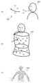
図8は、ゲーム世界に配置されたオブジェクトの例を示す。図8(a)に示す木310は、図8(b)に拡大して示すように、多数の光の粒子312により構成される。オブジェクト制御部203は、木310を構成する粒子312をゆらゆらと揺動させる。
図9は、ゲーム世界に配置されたプレイヤーキャラクタの例を示す。図9(a)に示すように、プレイヤーキャラクタ300の形状は、プレイヤーの体を模したモデル301により規定される。図9(b)に示すように、プレイヤーキャラクタ300は、モデル301の中に配置された、ベースとなるガス状の薄いベースボディ302と、ベースボディ302の中や周囲を移動する多数の光の粒子303により表現される。ベースボディ302の内部には、粒子303の配置位置や移動先などを指定するためのロケータ304が配置されている。プレイヤーキャラクタ制御部202は、ベースボディ302をその場でゆっくりと揺動させるとともに、粒子303をモデル301の内部で行き来させる。
プレイヤーキャラクタ制御部202は、プレイヤーの意識レベルによって段階的にプレイヤーキャラクタ300の表示態様を変化させるとともに、プレイヤーのリラックスレベル、呼吸や浄化などのアクションによってリアルタイムに表示態様を変化させる。
プレイヤーキャラクタ制御部202は、プレイヤーのリラックスレベルに応じてベースボディ302のサイズや色を変化させる。例えば、プレイヤーのリラックスレベルが高いほど、ベースボディ302を大きくし、白に近い色に変化させる。また、プレイヤーキャラクタ制御部202は、プレイヤーのリラックスレベルに応じて粒子303の移動速度を変化させる。例えば、プレイヤーのリラックスレベルが高いほど、粒子303の移動速度を遅くする。これにより、プレイヤーのリラックスレベルを視覚的に分かりやすく示すことができる。
プレイヤーキャラクタ制御部202は、プレイヤーの意識レベルに応じて、ベースボディ302の下半身の長さ、下半身から発生する粒子303の量、ベースボディ302を包む光の強さ又は色、光の強さ又は色が変化する速度、色の種類などを変化させる。これにより、プレイヤーは、自身の意識レベルを容易に客観視することができるとともに、他のプレイヤーのプレイヤーキャラクタがゲーム画面に表示される場合には、他のプレイヤーの意識レベルも容易に把握することができる。
プレイヤーキャラクタ制御部202は、プレイヤーが入力装置20を胸の辺りで保持している間、プレイヤーキャラクタ300が手を胸に当てている様子を表示するとともに、粒子303の移動速度を速くし、粒子303の光を強くし、粒子303がプレイヤーキャラクタ300の体内を流れるときの音を変化させることにより、プレイヤーキャラクタ300の体が浄化され、エネルギーが体いっぱいに満ちた感覚を演出する。このとき、エネルギー管理部206は、プレイヤーのエネルギーを増加させる。
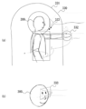
図10及び図11は、プレイヤーが呼吸するときのプレイヤーキャラクタの映像表現の例を示す。プレイヤーキャラクタ制御部202は、撮像装置14により撮像されたプレイヤーの画像を解析し、プレイヤーの肩の上下の動きや胸の前後の動きなどからプレイヤーの呼吸動作を把握する。プレイヤーが息を吸っている間、プレイヤーキャラクタ制御部202は、図10(a)に示すように、プレイヤーキャラクタ300の顔の前方に粒子を出現させ、プレイヤーキャラクタ300の口に向けて移動させる。また、図10(b)に示すように、プレイヤーキャラクタ300のモデル301を膨張させる。このとき、図10(c)に示すように、モデル301内の粒子303が分散するので密度が薄くなる。プレイヤーが息を吐いている間、プレイヤーキャラクタ制御部202は、図11(a)に示すように、プレイヤーキャラクタ300の顔の前方に残っていた粒子320を口から離れるように移動させる。また、図11(b)に示すように、プレイヤーキャラクタ300のモデル301を収縮させる。このとき、図11(c)に示すように、モデル301内の粒子303が凝集するので密度が濃くなり、モデル301の形状が明確になる。このように、呼吸の動作を可視化することにより、プレイヤーに呼吸を意識させることができる。
図12は、プレイヤーキャラクタとオブジェクト又は粒子との相互作用について説明するための図である。吸収制御部205は、プレイヤーキャラクタ300の周囲の第1の範囲331内にある粒子330をプレイヤーキャラクタ300の方に移動させる。第1の範囲331は、プレイヤーキャラクタ300の周囲に設定され、カプセル状の形状を有する。この第1の範囲331と粒子330とのコリジョン判定及びプレイヤーキャラクタ300への移動は、オブジェクトに対しては実行されない。
判定部204は、ゲーム世界に配置されている粒子330又はオブジェクトが、プレイヤーキャラクタ300の周囲の第2の範囲332の境界と接触したか否かを判定する。第2の範囲332は、第1の範囲331よりも狭く、プレイヤーキャラクタ300のモデルに近似した形状を有する。粒子330又はオブジェクトが第2の範囲332に入ったと判定された場合、吸収制御部205は、粒子330又はオブジェクトの表示態様を、プレイヤーキャラクタと接触したことを表す表示態様に変化させる。例えば、吸収制御部205は、粒子330又はオブジェクトの種類に応じた色で粒子330又はオブジェクトを光らせる。また、吸収制御部205は、第2の範囲332内にある粒子330に音源を設定し、粒子330又はオブジェクトの種類に応じた音を音源から発する。別の例では、第2の範囲332とは異なる第4の範囲内にある粒子330に音源を設定してもよい。
吸収制御部205は、プレイヤーキャラクタの目の前方の第3の範囲333の中に入らないように粒子330を移動させる。例えば、吸収制御部205は、第3の範囲333の境界に接触した粒子330を第3の範囲333の境界に沿って移動させる。これにより、ヘッドマウントディスプレイ100を使用してゲーム画面を見ているプレイヤーの目に粒子が当たってくるような映像が表示されないようにすることができる。
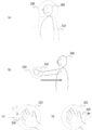
図13は、粒子がプレイヤーキャラクタに吸収される際の吸収アクションの例を示す。粒子330がプレイヤーキャラクタ300の顔又は体に接触した場合は、図13(a)に示すように、吸収制御部205は、粒子330が第2の範囲332内を移動したときのベクトルのままプレイヤーキャラクタ300の体内に進入させ、徐々に薄くして透明にし、所定時間後に消去する。図13(c)に示すように、粒子330がプレイヤーキャラクタ300の手に接触した場合は、図13(d)に示すように、吸収制御部205は、粒子330を所定時間手の周りで回転させた後、図13(b)に示すように、プレイヤーキャラクタ300の肩付近まで移動させ、さらに胸の中心に向かって移動させながら徐々に薄くして透明にし、所定時間後に消去する。エネルギー管理部206は、プレイヤーキャラクタ300に吸収された粒子330の個数を獲得エネルギーとして加算する。
図14は、粒子がプレイヤーキャラクタに吸収される際の吸収アクションの別の例を示す。図13(d)に示すように粒子330がプレイヤーキャラクタ300の手の周りを回転しているときに、プレイヤーが入力装置20をゆっくり動かすと、図14(a)に示すように、吸収制御部205は、粒子330をプレイヤーキャラクタ300の手の周りで継続して回転させる。図14(b)に示すように手を動かしていたプレイヤーが、手の動きを止めると、図14(c)に示すように、吸収制御部205は、プレイヤーキャラクタ300の手の周りを回転していた粒子330の回転速度を徐々に遅くしつつ、回転半径を小さくして手に近づけた後、図14(d)に示すように、腕から肩を経て胸に吸収させる。
別の例では、吸収制御部205は、プレイヤーキャラクタ300の体内に吸収された粒子330を、プレイヤーキャラクタ300に含まれる粒子303とともにプレイヤーキャラクタ300の内部に存在させてもよい。これにより、プレイヤーが獲得したエネルギーの量をプレイヤーキャラクタ300の体内にある粒子の粗密により視覚的に分かりやすく示すことができる。プレイヤーキャラクタ300の体を構成する粒子303とは異なる表示態様で吸収された粒子330を表示してもよい。この例において、プレイヤーキャラクタ300内に多数の粒子が蓄積されると、個々の粒子を揺動させるための処理負荷が増大するので、画像生成部207は、粒子の個数に拘泥せずに、所定数(例えば、10個)の粒子を1つの粒子にまとめて表示する。このとき、画像生成部207は、まとめられた粒子を元の粒子とは異なる表示態様で表示してもよい。例えば、粒径、形状、表示色、透明度などを変更してもよい。表示される粒子の合計数が少なくなり過ぎないようにするために、画像生成部207は、所定数の粒子を1つの粒子にまとめることにより表示される粒子の合計数が所定数(例えば、100個)を下回る場合は、まとめて表示する粒子の数を制御することにより、表示される粒子の合計数が所定数以上となるようにしてもよい。同様に、音声生成部208は、所定数の粒子の音源を1つの音源にまとめて音声を生成する。これにより、映像や音声による効果を維持しつつ処理負荷を軽減させることができる。
プレイヤーキャラクタ300がオブジェクトに接触した場合も、浮遊する粒子と接触した場合と同様に、オブジェクトからエネルギーを吸収することができる。吸収制御部205は、プレイヤーキャラクタ300の第2の範囲332の境界がオブジェクトに触れている間、オブジェクト固有の効果音と呼吸音を音声生成部208に生成させ、オブジェクトに触れている手を通してプレイヤーキャラクタ300の体に粒子が流れ込むように移動させる。エネルギー管理部206は、プレイヤーキャラクタ300がオブジェクトからエネルギーを吸収している間、オブジェクトが持つエネルギー量を減少させる。プレイヤーキャラクタ300がオブジェクトから手を放すと、吸収制御部205は、エネルギー吸収を中断する。吸収制御部205は、オブジェクトのエネルギー量が0になると、エネルギー吸収を終了する。エネルギーの量が0になったオブジェクトは、プレイヤーキャラクタ300が再び触ってもエネルギーを吸収することができない。
本実施の形態では、オブジェクトが持つエネルギーの量は、固有のパラメーターとして予め定められており、基本的には、プレイヤーはこの値以上のエネルギーをオブジェクトから吸収する事はできないが、プレイヤーキャラクタとオブジェクトとが共鳴、調和することにより、プレイヤーはオブジェクトが持つ固有のエネルギー量以上のエネルギーを吸収することができる。
上述したように、プレイヤーキャラクタ300がオブジェクトに触れている間、吸収制御部205は、そのオブジェクトの呼吸音を音声生成部208に生成させるが、プレイヤーがその呼吸音に自身の呼吸を同期させると、エネルギー管理部206は、オブジェクトが放出可能なエネルギー量を増加させる。これにより、プレイヤーに呼吸動作をさらに意識させることができ、正しい呼吸法による精神状態及び健康状態の向上を促すことができる。
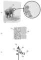
図15は、オブジェクトを構成する粒子がプレイヤーキャラクタに吸収される際の吸収アクションの例を示す。図15(a)に示すように、ゲーム世界に配置された象314などの動物も、複数の粒子により構成されている。図15(b)に示すように、プレイヤーキャラクタ300の手が象314に触れると、図15(c)に示すように、吸収制御部205は、象314を構成する粒子315がプレイヤーキャラクタ300の手から体内に吸収される様子を表すアクションを実行する。象314の表面を構成する粒子315と、プレイヤーキャラクタ300の手を構成する粒子303は、異なる外観を有していてもよい。例えば、図15(c)に示すように、象314を構成する粒子315とプレイヤーキャラクタ300を構成する粒子303は、異なる粒径、形状、表示色、透明度などを有していてもよい。これにより、プレイヤーキャラクタ300の体内に吸収された粒子316が象314に由来するものであることが明確に認識されるので、象314と同化したような感覚をプレイヤーに与えることができる。吸収制御部205は、プレイヤーキャラクタ300の体内に吸収された粒子316をプレイヤーキャラクタ300の手から腕を経由して胸の方へ移動させる。これにより、象314から吸収したエネルギーがプレイヤーの体内に染みこんでいくような感覚をプレイヤーに与えることができる。吸収制御部205は、プレイヤーキャラクタ300の体内に吸収された粒子315を移動させつつ、プレイヤーキャラクタ300を構成する粒子303と同じ外観に変化させてもよい。これにより、象314から吸収したエネルギーがプレイヤー自身のエネルギーに変換されたような感覚をプレイヤーに与えることができる。象314を構成する粒子315とプレイヤーキャラクタ300を構成する粒子303は、同一又は類似の外観を有していてもよい。これにより、ゲーム世界に存在するもの全てが同一又は類似の粒子により構成されていて、互いにエネルギーを交換可能であるという世界観を表現することができる。また、象314から吸収したエネルギーがプレイヤーの体内に蓄積される感覚をプレイヤーに与えることができる。
図16は、プレイヤーキャラクタと粒子との相互作用の別の例を示す。プレイヤーが所定値以上のエネルギーを獲得しているときに、図16(a)及び図16(b)に示すように、入力装置20a及び20bを近づけてプレイヤーキャラクタ300の両手を近づけると、エネルギー管理部206は、両手の間にエネルギーの粒子330を表示し、徐々に粒子330の数を増加させる。そのまま数秒経過すると、図16(c)に示すように、エネルギー管理部206は、粒子330の表示態様を変化させ、新しいオブジェクトを生み出すことができる状態になったことをプレイヤーに示す。プレイヤーが手を動かしながら両手の間を離していくと、図16(d)に示すように、エネルギー管理部206は、プレイヤーキャラクタ300の両手の間に表示された粒子群の形状を変化させ、最終的に、図16(e)に示すように、オブジェクト340を形成させてプレイヤーキャラクタ300の周囲を移動させる。これにより、多くのエネルギーを蓄積する動機をプレイヤーに与えることができる。
図17は、実施の形態に係るゲーム制御方法の手順を示すフローチャートである。オブジェクト制御部203は、仮想三次元空間に配置された、複数の粒子を含むオブジェクトを制御し(S10)、プレイヤーキャラクタ制御部202は、仮想三次元空間に配置された、プレイヤーが操作可能なプレイヤーキャラクタを制御し(S12)、画像生成部207は、仮想三次元空間の画像を生成する(S14)。判定部204は、プレイヤーキャラクタとオブジェクトとが接触したか否かを判定する(S16)。接触してない場合は(S16のN)、S10に戻る。接触している場合は(S16のY)、吸収制御部205は、プレイヤーキャラクタと接触したオブジェクトに含まれる複数の粒子がプレイヤーキャラクタに吸収される様子を表すアクションを実行させる(S18)。ゲームを終了しない場合は(S20のN)、S10に戻り、ゲームを終了する場合は(S20のY)、処理を終了する。
以上、本発明を実施の形態をもとに説明した。この実施の形態は例示であり、それらの各構成要素や各処理プロセスの組合せにいろいろな変形例が可能なこと、またそうした変形例も本発明の範囲にあることは当業者に理解されるところである。
本発明は、表示装置への表示を制御する表示制御装置に利用可能である。
1 ゲームシステム、3 ゲームサーバ、10ゲーム装置、11 処理装置、12 出力制御装置、13 記憶装置、14 撮像装置、15 出力装置、20 入力装置、100 ヘッドマウントディスプレイ、201 視点制御部、202 プレイヤーキャラクタ制御部、203 オブジェクト制御部、204 判定部、205 吸収制御部、206 エネルギー管理部、207 画像生成部、208 音声生成部。
Claims (19)
- コンピュータに、
仮想三次元空間の画像を生成する画像生成部と、
前記仮想三次元空間に配置された、複数の粒子を含むオブジェクトを制御するオブジェクト制御部と、
前記仮想三次元空間に配置された、プレイヤーが操作可能なプレイヤーキャラクタを制御するプレイヤーキャラクタ制御部と、
前記プレイヤーキャラクタと前記オブジェクトとが接触したか否かを判定する判定部と、
前記判定部により前記プレイヤーキャラクタと前記オブジェクトとが接触したと判定された場合、前記プレイヤーキャラクタと接触した前記オブジェクトに含まれる複数の粒子が前記プレイヤーキャラクタに吸収される様子を表すアクションを実行させる吸収制御部と、
を実現させるための表示制御プログラム。 - 前記プレイヤーキャラクタは、少なくとも前記プレイヤーの体の一部を表現したオブジェクトであり、
前記画像生成部は、前記プレイヤーキャラクタの目の位置の近傍に、前記仮想三次元空間の画像を生成するための視点位置を設定し、
前記プレイヤーキャラクタ制御部は、前記プレイヤーの手の動きに合わせて前記プレイヤーキャラクタの手の動きを制御する
ことを特徴とする請求項1に記載の表示制御プログラム。 - 前記画像生成部は、前記プレイヤーの頭部に装着されるヘッドマウントディスプレイに表示される画像を生成し、
前記画像生成部は、前記ヘッドマウントディスプレイの向きに合わせて、前記仮想三次元空間の画像を生成するための視線方向を変化させる
ことを特徴とする請求項2に記載の表示制御プログラム。 - 前記吸収制御部は、前記プレイヤーキャラクタの周囲の第1の範囲内にある粒子を前記プレイヤーキャラクタの方に移動させることを特徴とする請求項1から3のいずれかに記載の表示制御プログラム。
- 前記吸収制御部は、前記プレイヤーキャラクタの周囲の前記第1の範囲よりも狭い第2の範囲に粒子が入ったときに、前記粒子の表示態様を、前記プレイヤーキャラクタと接触したことを表す表示態様に変化させることを特徴とする請求項4に記載の表示制御プログラム。
- 前記吸収制御部は、前記プレイヤーキャラクタの目の前方の第3の範囲の中に入らないように前記粒子を移動させることを特徴とする請求項4又は5に記載の表示制御プログラム。
- 前記吸収制御部は、前記粒子が前記プレイヤーキャラクタの表面に移動したときに、前記粒子の表示態様を、前記プレイヤーキャラクタに吸収されたことを表す表示態様に変化させることを特徴とする請求項1から6のいずれかに記載の表示制御プログラム。
- 前記プレイヤーキャラクタは複数の粒子を含み、
前記プレイヤーキャラクタに含まれる複数の粒子は、前記オブジェクトに含まれる複数の粒子とは異なる表示態様で表示される
ことを特徴とする請求項7に記載の表示制御プログラム。 - 前記プレイヤーキャラクタに含まれる複数の粒子は、前記オブジェクトに含まれる複数の粒子とは異なる粒径を有することを特徴とする請求項8に記載の表示制御プログラム。
- 前記プレイヤーキャラクタに含まれる複数の粒子は、前記オブジェクトに含まれる複数の粒子とは異なる表示色で表示されることを特徴とする請求項8又は9に記載の表示制御プログラム。
- 前記吸収制御部は、前記プレイヤーキャラクタに吸収された粒子を、前記プレイヤーキャラクタに含まれる粒子とともに前記プレイヤーキャラクタの内部に存在させる
ことを特徴とする請求項8から10のいずれかに記載の表示制御プログラム。 - 前記吸収制御部は、前記プレイヤーキャラクタに吸収された粒子を移動させることを特徴とする請求項11に記載の表示制御プログラム。
- 前記吸収制御部は、前記プレイヤーキャラクタに吸収された粒子を消去することを特徴とする請求項7から10のいずれかに記載の表示制御プログラム。
- 前記画像生成部は、所定数の前記粒子を1つの粒子にまとめて表示することを特徴とする請求項1から13のいずれかに記載の表示制御プログラム。
- コンピュータに、前記仮想三次元空間における音声を生成する音声生成部を更に実現させ、
前記音声生成部は、前記プレイヤーキャラクタの周囲の第4の範囲内にある粒子に音源を設定し、前記音源から発せられる音声を生成する
ことを特徴とする請求項1から14のいずれかに記載の表示制御プログラム。 - 前記音声生成部は、所定数の前記粒子の音源を1つの音源にまとめて音声を生成することを特徴とする請求項15に記載の表示制御プログラム。
- 前記画像生成部は、他のプレイヤーが操作するプレイヤーキャラクタの情報をサーバから取得し、前記仮想三次元空間に他のプレイヤーが操作するプレイヤーキャラクタを配置した画像を生成することを特徴とする請求項1から16のいずれかに記載の表示制御プログラム。
- 仮想三次元空間の画像を生成する画像生成部と、
前記仮想三次元空間に配置された、複数の粒子を含むオブジェクトを制御するオブジェクト制御部と、
前記仮想三次元空間に配置された、プレイヤーが操作可能なプレイヤーキャラクタを制御するプレイヤーキャラクタ制御部と、
前記プレイヤーキャラクタと前記オブジェクトとが接触したか否かを判定する判定部と、
前記判定部により前記プレイヤーキャラクタと前記オブジェクトとが接触したと判定された場合、前記プレイヤーキャラクタと接触した前記オブジェクトに含まれる複数の粒子が前記プレイヤーキャラクタに吸収される様子を表すアクションを実行させる吸収制御部と、
を備えることを特徴とする表示制御装置。 - コンピュータに、
仮想三次元空間の画像を生成するステップと、
前記仮想三次元空間に配置された、複数の粒子を含むオブジェクトを制御するステップと、
前記仮想三次元空間に配置された、プレイヤーが操作可能なプレイヤーキャラクタを制御するステップと、
前記プレイヤーキャラクタと前記オブジェクトとが接触したか否かを判定するステップと、
前記プレイヤーキャラクタと前記オブジェクトとが接触したと判定された場合、前記プレイヤーキャラクタと接触した前記オブジェクトに含まれる複数の粒子が前記プレイヤーキャラクタに吸収される様子を表すアクションを実行させるステップと、
をコンピュータに実行させることを特徴とする表示制御方法。
Priority Applications (1)
| Application Number | Priority Date | Filing Date | Title |
|---|---|---|---|
| US17/292,770 US11951397B2 (en) | 2018-11-19 | 2019-11-12 | Display control program, display control device, and display control method |
Applications Claiming Priority (2)
| Application Number | Priority Date | Filing Date | Title |
|---|---|---|---|
| JP2018-216863 | 2018-11-19 | ||
| JP2018216863A JP7199204B2 (ja) | 2018-11-19 | 2018-11-19 | 表示制御プログラム、表示制御装置、及び表示制御方法 |
Publications (1)
| Publication Number | Publication Date |
|---|---|
| WO2020105503A1 true WO2020105503A1 (ja) | 2020-05-28 |
Family
ID=70774421
Family Applications (1)
| Application Number | Title | Priority Date | Filing Date |
|---|---|---|---|
| PCT/JP2019/044294 Ceased WO2020105503A1 (ja) | 2018-11-19 | 2019-11-12 | 表示制御プログラム、表示制御装置、及び表示制御方法 |
Country Status (3)
| Country | Link |
|---|---|
| US (1) | US11951397B2 (ja) |
| JP (1) | JP7199204B2 (ja) |
| WO (1) | WO2020105503A1 (ja) |
Families Citing this family (4)
| Publication number | Priority date | Publication date | Assignee | Title |
|---|---|---|---|---|
| US20220244540A1 (en) * | 2021-02-03 | 2022-08-04 | Htc Corporation | Tracking system |
| CN113689534B (zh) * | 2021-10-25 | 2022-03-01 | 腾讯科技(深圳)有限公司 | 物理特效渲染方法、装置、计算机设备和存储介质 |
| JP7543356B2 (ja) * | 2022-09-21 | 2024-09-02 | 株式会社コロプラ | プログラムおよび情報処理システム |
| JP7795114B2 (ja) * | 2023-02-27 | 2026-01-07 | 株式会社カプコン | プログラム、および音響制御装置 |
Citations (4)
| Publication number | Priority date | Publication date | Assignee | Title |
|---|---|---|---|---|
| JP2001276418A (ja) * | 2000-03-29 | 2001-10-09 | Namco Ltd | ゲーム装置、及び情報記憶媒体 |
| JP2004062676A (ja) * | 2002-07-30 | 2004-02-26 | Koei:Kk | プログラム、記録媒体、3次元群れ制御方法及びゲーム装置 |
| JP2012032951A (ja) * | 2010-07-29 | 2012-02-16 | Sony Computer Entertainment Inc | 情報処理装置および情報処理方法 |
| WO2017029915A1 (ja) * | 2015-08-17 | 2017-02-23 | 日本テレビ放送網株式会社 | プログラム、表示装置、表示方法、放送システム及び放送方法 |
Family Cites Families (4)
| Publication number | Priority date | Publication date | Assignee | Title |
|---|---|---|---|---|
| JP4307310B2 (ja) * | 2004-03-31 | 2009-08-05 | 任天堂株式会社 | ゲーム装置及びゲームプログラム |
| US10203762B2 (en) * | 2014-03-11 | 2019-02-12 | Magic Leap, Inc. | Methods and systems for creating virtual and augmented reality |
| JP6355978B2 (ja) * | 2014-06-09 | 2018-07-11 | 株式会社バンダイナムコエンターテインメント | プログラムおよび画像生成装置 |
| US10852838B2 (en) * | 2014-06-14 | 2020-12-01 | Magic Leap, Inc. | Methods and systems for creating virtual and augmented reality |
-
2018
- 2018-11-19 JP JP2018216863A patent/JP7199204B2/ja active Active
-
2019
- 2019-11-12 WO PCT/JP2019/044294 patent/WO2020105503A1/ja not_active Ceased
- 2019-11-12 US US17/292,770 patent/US11951397B2/en active Active
Patent Citations (4)
| Publication number | Priority date | Publication date | Assignee | Title |
|---|---|---|---|---|
| JP2001276418A (ja) * | 2000-03-29 | 2001-10-09 | Namco Ltd | ゲーム装置、及び情報記憶媒体 |
| JP2004062676A (ja) * | 2002-07-30 | 2004-02-26 | Koei:Kk | プログラム、記録媒体、3次元群れ制御方法及びゲーム装置 |
| JP2012032951A (ja) * | 2010-07-29 | 2012-02-16 | Sony Computer Entertainment Inc | 情報処理装置および情報処理方法 |
| WO2017029915A1 (ja) * | 2015-08-17 | 2017-02-23 | 日本テレビ放送網株式会社 | プログラム、表示装置、表示方法、放送システム及び放送方法 |
Also Published As
| Publication number | Publication date |
|---|---|
| US11951397B2 (en) | 2024-04-09 |
| JP2020086674A (ja) | 2020-06-04 |
| US20210394069A1 (en) | 2021-12-23 |
| JP7199204B2 (ja) | 2023-01-05 |
Similar Documents
| Publication | Publication Date | Title |
|---|---|---|
| JP6276882B1 (ja) | 情報処理方法、装置、および当該情報処理方法をコンピュータに実行させるためのプログラム | |
| JP6244593B1 (ja) | 情報処理方法、装置、および当該情報処理方法をコンピュータに実行させるためのプログラム | |
| JP6263252B1 (ja) | 情報処理方法、装置、および当該情報処理方法をコンピュータに実行させるためのプログラム | |
| JP6788327B2 (ja) | 表示制御プログラム、表示制御装置、及び表示制御方法 | |
| JP6290467B1 (ja) | 情報処理方法、装置、および当該情報処理方法をコンピュータに実行させるプログラム | |
| US20190073830A1 (en) | Program for providing virtual space by head mount display, method and information processing apparatus for executing the program | |
| US10545339B2 (en) | Information processing method and information processing system | |
| JP2016158795A (ja) | 表示制御プログラム、表示制御装置、及び表示制御方法 | |
| JP7199204B2 (ja) | 表示制御プログラム、表示制御装置、及び表示制御方法 | |
| JP6321263B1 (ja) | 情報処理方法、装置、および当該情報処理方法をコンピュータに実行させるためのプログラム | |
| JP6248219B1 (ja) | 情報処理方法、コンピュータ、および当該情報処理方法をコンピュータに実行させるためのプログラム | |
| JP6263292B1 (ja) | 情報処理方法、コンピュータ、および当該情報処理方法をコンピュータに実行させるためのプログラム | |
| JP2019032844A (ja) | 情報処理方法、装置、および当該情報処理方法をコンピュータに実行させるためのプログラム | |
| JP2018192238A (ja) | 情報処理方法、装置、および当該情報処理方法をコンピュータに実行させるためのプログラム | |
| JP2018195287A (ja) | 情報処理方法、装置、および当該情報処理方法をコンピュータに実行させるためのプログラム | |
| JP2018125003A (ja) | 情報処理方法、装置、および当該情報処理方法をコンピュータに実行させるプログラム | |
| JP6856572B2 (ja) | 情報処理方法、装置、および当該情報処理方法をコンピュータに実行させるためのプログラム | |
| JP6820299B2 (ja) | プログラム、情報処理装置、および方法 | |
| JP2018092635A (ja) | 情報処理方法、装置、および当該情報処理方法をコンピュータに実行させるためのプログラム | |
| JP2018124981A (ja) | 情報処理方法、装置、および当該情報処理方法をコンピュータに実行させるためのプログラム | |
| JP6330072B1 (ja) | 情報処理方法、装置、および当該情報処理方法をコンピュータに実行させるためのプログラム | |
| JP2018190196A (ja) | 情報処理方法、装置、および当該情報処理方法をコンピュータに実行させるためのプログラム | |
| JP2021064399A (ja) | プログラム、情報処理装置、および方法 | |
| TW201816545A (zh) | 虛擬實境頭戴式裝置 | |
| JP6891319B2 (ja) | 表示制御装置及び表示制御方法 |
Legal Events
| Date | Code | Title | Description |
|---|---|---|---|
| 121 | Ep: the epo has been informed by wipo that ep was designated in this application |
Ref document number: 19886757 Country of ref document: EP Kind code of ref document: A1 |
|
| NENP | Non-entry into the national phase |
Ref country code: DE |
|
| 122 | Ep: pct application non-entry in european phase |
Ref document number: 19886757 Country of ref document: EP Kind code of ref document: A1 |