WO2020105498A1 - ペレット及び反応器 - Google Patents
ペレット及び反応器Info
- Publication number
- WO2020105498A1 WO2020105498A1 PCT/JP2019/044172 JP2019044172W WO2020105498A1 WO 2020105498 A1 WO2020105498 A1 WO 2020105498A1 JP 2019044172 W JP2019044172 W JP 2019044172W WO 2020105498 A1 WO2020105498 A1 WO 2020105498A1
- Authority
- WO
- WIPO (PCT)
- Prior art keywords
- pellet
- catalyst
- pellets
- reactor
- diameter
- Prior art date
- Legal status (The legal status is an assumption and is not a legal conclusion. Google has not performed a legal analysis and makes no representation as to the accuracy of the status listed.)
- Ceased
Links
Images
Classifications
-
- B—PERFORMING OPERATIONS; TRANSPORTING
- B01—PHYSICAL OR CHEMICAL PROCESSES OR APPARATUS IN GENERAL
- B01J—CHEMICAL OR PHYSICAL PROCESSES, e.g. CATALYSIS OR COLLOID CHEMISTRY; THEIR RELEVANT APPARATUS
- B01J8/00—Chemical or physical processes in general, conducted in the presence of fluids and solid particles; Apparatus for such processes
- B01J8/02—Chemical or physical processes in general, conducted in the presence of fluids and solid particles; Apparatus for such processes with stationary particles, e.g. in fixed beds
Definitions
- the present disclosure relates to pellets and reactors.
- the purpose of the present disclosure is to suppress the bulk density of the pellets packed in the container from becoming excessively large or small by setting the ratio of the diameter of the pellets to the height to an appropriate value.
- the first aspect of the present disclosure is premised on cylindrical pellets to be filled in the container (20).
- the range of the diameter d of the cylindrical pellet (10) is set to 1.0 ⁇ d ⁇ 5.0, and the ratio ⁇ of the diameter d and the height h is 1.0 ⁇ ⁇ 1.6.
- the bulk density when the pellets (10) are filled in the container (20) does not vary and is stable, as shown in FIG. In other words, in the first aspect, it is possible to prevent the bulk density from increasing or decreasing excessively.
- a second aspect of the present disclosure is, in the first aspect, It is characterized in that the relationship of 1.0 ⁇ ⁇ 1.4 is satisfied.
- the ratio ⁇ of the diameter of the pellet (10) to the height is set in the range of 1.0 ⁇ ⁇ 1.4, the pellet (10) is placed in the container (20) as shown in FIG. It is possible to more effectively suppress the bulk density when filled with 10) from becoming excessively large or small.
- a third aspect of the present disclosure is, in the second aspect, It is characterized in that the relationship of 1.0 ⁇ ⁇ 1.2 is satisfied.
- the diameter-height ratio ⁇ of the pellet (10) is set in the range of 1.0 ⁇ ⁇ 1.2, the pellet (10) is placed in the container (20) as shown in FIG. It is possible to more effectively suppress the bulk density when filled with 10) from becoming excessively large or small.
- a fourth aspect of the present disclosure is the method according to any one of the first to third aspects,
- the pellet (10) is characterized in that it contains a catalyst component.
- a fifth aspect of the present disclosure is, in the fourth aspect,
- the catalyst component is composed of a crystalline substance.
- the sixth aspect of the present disclosure is premised on a reactor configured with a container (20) filled with pellets (10) for a chemical reaction for producing a chemical substance.
- This reactor is The pellet (10) is the pellet (10) according to any one of the first to fifth aspects,
- the container (20) is characterized by being a container (20) through which gas or liquid flows.
- This reactor constitutes a pellet filling system for a chemical reaction by being filled with the pellets (10) according to the first to fifth aspects, and can be used as an industrial mixture with the pellets (10) according to the first to fifth aspects.
- the fields of use of are the same, and the problems to be solved are the same.
- the pellet (10) filled in the container (20) and the gas or liquid come into efficient contact with each other.
- the pellet (10) is the catalyst pellet (10) and the gas is the reaction gas, it is possible to suppress the decrease in the reactivity of the catalyst.
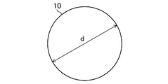
- FIG. 1 is a plan view of a catalyst pellet according to the embodiment.
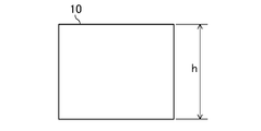
- FIG. 2 is a front view of the catalyst pellet of FIG.
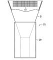
- FIG. 3 is a partial cross-sectional front view of a pellet filling system in which a reactor is filled with catalyst pellets.
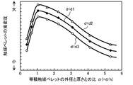
- FIG. 4 is a graph showing the bulk density of the catalyst pellets of the embodiment.
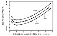
- FIG. 5 is a graph showing the average stress of the catalyst pellet of the embodiment.
- This embodiment relates to a pellet (10) filled in a container such as a reactor (20) of a chemical substance manufacturing facility, and a reactor (20) filled with the pellet (10).
- the pellet (10) is a pellet containing a catalyst component (catalyst pellet). As shown in FIGS. 1 and 2, the catalyst pellets (10) are columnar pellets.
- the catalyst pellets (10) are formed of powder (catalyst particles) of a crystalline substance such as chromium oxide (Cr 2 O 3 ), zinc oxide (ZnO), aluminum oxide (Al 2 O 3 ).
- the diameter dimension of the catalyst pellet (10) is indicated by d (mm) and the height dimension of the cylinder is indicated by h (mm).
- the diameter dimension d of the catalyst pellet (10) is 1.0 ⁇ d ⁇ 5.0.
- the diameter dimension d of the catalyst pellet (10) is more preferably 2.0 ⁇ d ⁇ 4.0.
- FIG. 3 is a partial cross-sectional front view of a pellet filling system (25) in which the reactor (20) is filled with pellets (10).
- the pellet filling system (25) has a reactor (20) and a filling pipe (21).
- the reactor (20) is a cylindrical container in which a reaction gas flows.
- the reactor (20) is made of, for example, stainless steel (SUS304).
- the filling pipe (21) is inserted into the reactor (20) from above.
- the opening-side portion of the upper portion of the filling pipe (21) has a shape in which the opening diameter increases from the lower side to the upper side.
- the catalyst pellets (10) are packed into the reactor (20) in random directions by dropping them into the reactor (20) using a packing pipe (21).
- the diameter of the reactor (20) is not particularly limited, but is preferably 20 mm to 3000 mm, more preferably 30 mm to 1000 mm, and further preferably 40 mm to 100 mm.
- the results will be described with reference to the graphs of FIGS. 4 and 5.
- the graphs of FIGS. 4 and 5 show the values of the bulk density and the value of the average stress when the ratio ⁇ changes for the three types of catalyst pellets (10), respectively.
- the average stress is the average value of the stress of each catalyst pellet (10) generated by the weight of the catalyst pellet (10) filled in the reactor (20), and the relative stress generated in the upper catalyst pellet (10). It is a value obtained from a small stress, an intermediate magnitude stress generated in the middle catalyst pellet (10), and a relatively large stress generated in the lower catalyst pellet (10).
- the catalyst pellet (10) of the present embodiment is an equal volume catalyst pellet (10) whose volume does not change even if the diameter-height ratio ⁇ changes.
- a catalyst pellet (10) having a diameter d1 is an equal volume catalyst pellet (10) having a basic shape of a pellet (10) having d1 of 3.5 (mm) when the ratio ⁇ is 1.
- d1 3.5 (mm)
- the height h is also 3.5 (mm)
- the diameter d1 changes the height h changes while the volume remains the same.
- the ratio ⁇ of the diameter to the height is 1.0 ⁇ ⁇ 1.4 (second range)
- the ratio ⁇ of diameter to height is 1.0 ⁇ ⁇ 1.2 (third range)
- the diameter-height ratio ⁇ is 1.0 ⁇ ⁇ 1.4 (second range)
- the diameter-height ratio ⁇ is 1.0 ⁇ ⁇ 1.2 (third range) or 1.05 ⁇ ⁇ ⁇ 1.15 (fourth range)
- the average stress is small and the deformation occurs. It is possible to more effectively meet the conditions that are difficult to pulverize.
- the catalyst pellet (10) having low strength can be filled in the reactor (20) and used for the reaction while preventing pulverization.
- the present embodiment is particularly suitable for the catalyst pellet (10) made of crystalline powder (catalyst particles) having relatively low strength.
- a conventional cylindrical catalyst pellet packed in a reactor has a diameter d of 0.5 mm to 10 mm and a height h of 0.5 mm as described in, for example, International Publication WO2002 / 070129. There is one that makes it 15mm.
- the bulk density of the catalyst pellets (10) packed in the reactor (20) is smaller than that of the equal volume catalyst pellets (10) having ⁇ ⁇ 1 or 1.6 ⁇ . It is stable and can prevent the bulk density from increasing or decreasing excessively.
- the packing rate of the catalyst pellets (10) in the reactor (20) is increased. Be done. As a result, it is possible to prevent the reaction gas from efficiently contacting the catalyst pellet (10) and reducing the reactivity of the catalyst.
- the ratio ⁇ of the diameter d and the height h is set in the second range of 1.0 ⁇ ⁇ 1.4, the bulk density is high and the filling rate is high.
- the condition can be more effectively satisfied.
- the ratio ⁇ is set to the third range of 1.0 ⁇ ⁇ 1.2 or the fourth range of 1.05 ⁇ ⁇ ⁇ 1.15, the bulk density is stable and the filling rate is high. It is possible to more effectively meet the high condition.
- the catalyst to the reactor (20) is increased. Since the packing density of the pellets (10) can be increased and the bulk density can be stabilized, it is easy to suppress the decrease in the reactivity of the catalyst.
- the reaction as shown in FIG. The average stress when the catalyst pellet (10) is filled in the vessel (20) is smaller than that of the equal volume catalyst pellet (10) with ⁇ ⁇ 1 or 1.6 ⁇ .
- the catalyst pellets (10) filled in the reactor (20) are almost even. It becomes difficult to deform.
- the diameter-height ratio ⁇ in the second range of 1.0 ⁇ ⁇ 1.4, it is possible to more effectively meet the condition that the average stress is small and deformation is difficult. Further, when the ratio ⁇ is set to the third range of 1.0 ⁇ ⁇ 1.2 or the fourth range of 1.05 ⁇ ⁇ ⁇ 1.15, the condition that the average stress is small and deformation is difficult is further Can be effectively met. As described above, as the diameter-height ratio ⁇ is narrowed to the second range from the first range and further to the third range from the second range, the average stress of the catalyst pellet (10) becomes smaller. Become.
- the catalyst pellets (10) have low strength, and when such a catalyst pellet (10) is filled in the reactor (20), the catalyst pellets (10) existing in the surroundings receive a force and are destroyed. May be pulverized. If the catalyst pellets (10) are pulverized, the flowability of the reaction gas may be reduced, and in some cases, the reaction gas may not flow (clogging). Therefore, when there are many powdered catalyst pellets (10), the reaction is stopped, the catalyst pellets (10) containing the powdered substance are extracted from the reactor (20), the powdered substance is removed, and the catalyst pellets (10) are removed again. This will cause the trouble of filling.
- the stress of the catalyst pellets (10) is reduced, and the powder is less likely to be pulverized, so that the flowability of the reaction gas can be suppressed from decreasing.
- a relatively weak strength catalyst pellet (10) formed of a crystalline material such as chromium oxide (Cr 2 O 3 ), zinc oxide (ZnO), aluminum oxide (Al 2 O 3 ), Insufficient strength can be effectively suppressed.
- the above embodiment may have the following configurations.
- the present disclosure is applicable not only to the catalyst pellets (10) used in the chemical substance manufacturing facility, but also to the catalyst pellets (10) for other purposes such as the catalyst pellets used in the facility for decomposing harmful substances. Further, in the above embodiment, the catalyst pellet (10) containing the powder of the crystalline substance (catalyst particles) has been described, but the pellet (10) of the present disclosure is a columnar catalyst containing a catalyst layer (layered catalyst). Other forms of catalyst pellets (10) such as pellets (10) are also applicable.
- the pellet of the present disclosure is not limited to the catalyst pellet (10) and may be another type of pellet.
- a pellet (10) of the present disclosure includes a pellet (10) containing a desiccant for removing water in a fluid to be contacted, or a pellet (10) containing an adsorbent that adsorbs a specific substance in the fluid to be contacted.
- the container (20) is not limited to gas, but may be a liquid in which liquid flows.
- the present disclosure is useful for pellets.
Landscapes
- Chemical & Material Sciences (AREA)
- Organic Chemistry (AREA)
- Chemical Kinetics & Catalysis (AREA)
- Devices And Processes Conducted In The Presence Of Fluids And Solid Particles (AREA)
- Catalysts (AREA)
Abstract
容器に充填される円柱状のペレットの直径をd(mm)とし、高さをh(mm)とし、直径と高さの比をα=d/hとすると、1.0≦d≦5.0、及び1.0<α≦1.6にする。
Description
本開示は、ペレット及び反応器に関するものである。
従来、円柱状のペレット(触媒ペレット)を容器(反応器)の内部に充填し、容器内で化学反応を行う技術が知られている。特許文献1には、ペレットの直径dを0.5mm~10mmとし、高さ(長さ)を0.5mmから15mmにすることが記載されている。ペレットの直径と高さの比αをα=d/hとすると、αは0.03~20になる。
ところで、特許文献1では、上記の比αが広範囲であるため、嵩密度が大きくなりすぎたり小さくなりすぎたりすることがある。容器へのペレットの充填が過密(嵩密度が大)である場合、ガスの流通性が低下したり、差圧が発生したりするなど、望まない現象が発生することがある。逆に、容器へのペレットの充填が過疎(嵩密度が小)である場合、ガスが触媒に効率よく接触しなくなるおそれがある。その結果、いずれの場合も、触媒の反応性が低下する問題が生じてしまう。このことは、嵩密度が大きくなりすぎたり小さくなりすぎたりすることに起因すると考えられる。
本開示の目的は、ペレットの直径と高さの比を適切な値にすることにより、容器に充填されるペレットの嵩密度が過度に大きくなったり小さくなったりするのを抑制することである。
本開示の第1の態様は、容器(20)に充填される円柱状のペレットを前提とする。
このペレットは、円柱の直径をd(mm)とし、円柱の高さをh(mm)とし、直径と高さの比αをα=d/hとすると、
1.0≦d≦5.0、及び
1.0<α≦1.6の関係を満たすことを特徴とする。
1.0≦d≦5.0、及び
1.0<α≦1.6の関係を満たすことを特徴とする。
第1の態様では、円柱状のペレット(10)の直径dの範囲を1.0≦d≦5.0に定め、直径dと高さhの比αを1.0<α≦1.6の範囲に定めているので、図4に示すように、容器(20)にペレット(10)を充填したときの嵩密度がバラつかずに安定する。言い換えると、第1の態様では、嵩密度が過度に大きくなったり小さくなったりするのを抑制できる。
本開示の第2の態様は、第1の態様において、
1.0<α≦1.4の関係を満たすことを特徴とする。
1.0<α≦1.4の関係を満たすことを特徴とする。
第2の態様では、ペレット(10)の直径と高さの比αを1.0<α≦1.4の範囲に定めているので、図4に示すように、容器(20)にペレット(10)を充填したときの嵩密度が過度に大きくなったり小さくなったりするのを、より効果的に抑制できる。
本開示の第3の態様は、第2の態様において、
1.0<α≦1.2の関係を満たすことを特徴とする。
1.0<α≦1.2の関係を満たすことを特徴とする。
第3の態様では、ペレット(10)の直径と高さの比αを1.0<α≦1.2の範囲に定めているので、図4に示すように、容器(20)にペレット(10)を充填したときの嵩密度が過度に大きくなったり小さくなったりするのを、さらに効果的に抑制できる。
本開示の第4の態様は、第1から第3の態様の何れか1つにおいて、
ペレット(10)が触媒成分を含むことを特徴とする。
ペレット(10)が触媒成分を含むことを特徴とする。
本開示の第5の態様は、第4の態様において、
触媒成分が結晶性物質により構成されていることを特徴とする。
触媒成分が結晶性物質により構成されていることを特徴とする。
第4,第5の態様では、触媒成分を含むペレット(触媒ペレット)(10)を容器(20)に充填したときに、嵩密度が過度に大きくなったり小さくなったりするのを抑制できる。
本開示の第6の態様は、ペレット(10)が充填される、化学物質を製造する化学反応のための容器(20)で構成される反応器を前提とする。
この反応器は、
上記ペレット(10)が第1から第5の態様の何れか1つのペレット(10)であり、
上記容器(20)は、内部を気体または液体が流通する容器(20)であることを特徴とする。
上記ペレット(10)が第1から第5の態様の何れか1つのペレット(10)であり、
上記容器(20)は、内部を気体または液体が流通する容器(20)であることを特徴とする。
この反応器は、第1から第5の態様のペレット(10)が充填されて化学反応用のペレット充填システムを構成するものであり、第1から第5の態様のペレット(10)と産業上の利用分野が同一で、解決しようとする課題も同一である。
第6の態様では、容器(20)内に充填されたペレット(10)と気体または液体とが効率よく接触する。ペレット(10)が触媒ペレット(10)であり、気体が反応ガスである場合、触媒の反応性が低下するのを抑制できる。
以下、実施形態を図面に基づいて詳細に説明する。
本実施形態は、化学物質製造設備の反応器(20)などの容器に充填されるペレット(10)と、このペレット(10)が充填される反応器(20)に関するものである。このペレット(10)は触媒成分を含むペレット(触媒ペレット)である。図1及び図2に示すように、この触媒ペレット(10)は円柱状のペレットである。この触媒ペレット(10)は、酸化クロム(Cr2O3)や酸化亜鉛(ZnO)、酸化アルミニウム(Al2O3)などの結晶性物質の粉末(触媒粒子)から形成されている。
図1,図2では、触媒ペレット(10)の直径寸法をd(mm)、円柱の高さ寸法をh(mm)で示している。本実施形態において、触媒ペレット(10)の直径寸法dは1.0≦d≦5.0である。触媒ペレット(10)の直径寸法dは、2.0≦d≦4.0であることがより好ましい。
図3は、反応器(20)にペレット(10)が充填されるペレット充填システム(25)の部分断面正面図である。ペレット充填システム(25)は、反応器(20)と充填管(21)を有している。反応器(20)は円筒状の容器であり、内部を反応ガスが流通する。反応器(20)は例えばステンレス鋼(SUS304)で形成されている。反応器(20)には、上方から充填管(21)が挿入される。充填管(21)の上部の開口側の部分は、下方から上方へ向かって開口直径が大きくなる形状である。触媒ペレット(10)は、充填管(21)を用いて反応器(20)に落下させることにより、反応器(20)の中にランダムな向きで充填される。反応器(20)の直径は特に限定されないが、20mm~3000mmであることが好ましく、30mm~1000mmであることがより好ましく、40mm~100mmであることがさらに好ましい。
次に、反応器(20)に充填した円柱状の触媒ペレット(10)の直径と高さの比αについて、触媒ペレット(10)の嵩密度と触媒ペレット(10)にかかる平均応力を求めた結果を示す図4,図5のグラフを用いて説明する。図4及び図5のグラフは、それぞれ、3種類の触媒ペレット(10)について、上記の比αが変化したときの嵩密度の値及び平均応力の値を表している。
なお、平均応力は、反応器(20)内に充填した触媒ペレット(10)の自重により生じる各触媒ペレット(10)の応力の平均値であり、上部の触媒ペレット(10)に生じる相対的に小さな応力や、中間部の触媒ペレット(10)に生じる中間的な大きさの応力や、下部の触媒ペレット(10)に生じる相対的に大きな応力から求めた値である。
本実施形態の触媒ペレット(10)は、直径と高さの比αが変化しても体積が変化しない等積触媒ペレット(10)である。図4において、直径dがd1の触媒ペレット(10)は、上記の比αが1のときにd1が3.5(mm)のペレット(10)を基本形状とする等積触媒ペレット(10)であり、d1=3.5(mm)のときは高さhも3.5(mm)で、直径d1が変化すると体積が同じままで高さhが変化する。
直径dがd2の触媒ペレット(10)は、上記の比αが1のときにd1が1.1(mm)のペレット(10)を基本形状とする等積触媒ペレット(10)であり、d1=1.1(mm)のときは高さhも1.1(mm)で、直径d1が変化すると体積が同じままで高さhが変化する。直径dがd3の触媒ペレット(10)は、上記の比αが1のときにd1が5.0(mm)のペレット(10)を基本形状とする等積触媒ペレット(10)であり、d1=5.0(mm)のときは高さhも5.0(mm)で、直径d1が変化すると体積が同じままで高さhが変化する。
図4のグラフより、直径と高さの比αが約0.4~約5.5まで変化すると、反応器(20)内の触媒ペレット(10)の嵩密度が大きく変化することと、直径dと高さhの比α(=d/h)が1.0<α≦1.6(第1の範囲)であると、α≦1や1.6<αである等積触媒ペレット(10)に比べて、反応器(20)内の嵩密度のバラつきが小さくなることが分かる。言い換えると、比αが1.0<α≦1.6であると、嵩密度が過度に大きくなったり小さくなったりするのが抑制される。特に、直径dと高さhの比αが1.0<α≦1.6であると、嵩密度が高い値で安定する。そのため、反応器(20)への触媒ペレット(10)の充填率を高められる。
また、直径と高さの比αが1.0<α≦1.4(第2の範囲)であると、嵩密度が高い値で安定して充填率が高くなる条件を、より効果的に満たすことができる。直径と高さの比αが1.0<α≦1.2(第3の範囲)であると、嵩密度が高い値で安定して充填率が高くなる条件を、さらに効果的に満たすことができる。また、1.05≦α≦1.15(第4の範囲)としてもよい。
一方、図5のグラフより、直径と高さの比αが約0.4~約5.5まで変化すると、反応器(20)内の触媒ペレット(10)の平均応力が大きく変化することと、直径dと高さhの比αが1.0<α≦1.6(第1の範囲)であると、α≦1や1.6<αである等積触媒ペレット(10)に比べて、平均応力が小さくなることが分かる。そのため、直径と高さの比αが1.0<α≦1.6であると、触媒ペレット(10)が砕けにくく変形しにくくなる。
また、直径と高さの比αが1.0<α≦1.4(第2の範囲)であると、平均応力が小さくて砕けにくく変形しにくい条件を、より効果的に満たすことができる。直径と高さの比αが1.0<α≦1.2(第3の範囲)や1.05≦α≦1.15(第4の範囲)であると、平均応力が小さくて変形、粉化しにくい条件を、さらに効果的に満たすことができる。
本実施形態では、触媒ペレット(10)の平均応力が小さくなるので、強度の低い触媒ペレット(10)を反応器(20)に充填して、粉化を防ぎながら反応に使用できる。本実施形態は、特に、比較的強度が弱い結晶性の粉末(触媒粒子)から作成した触媒ペレット(10)に適している。
-実施形態の効果-
反応器に充填される従来の円柱状の触媒ペレットには、例えば国際公開第WO2002/070129号パンフレットに記載されているように、直径dを0.5mm~10mmとし、高さhを0.5mmから15mmにするものがある。この場合、触媒ペレット(10)の直径dと高さhの比α(=d/h)αは0.03~20である。この比αの値の範囲は、本実施形態に比べて広いため、従来の触媒ペレットでは嵩密度のバラつきが大きくなりやすいことが分かる。そのため、反応器に触媒ペレットを充填すると、反応器内で触媒ペレットが過密になったり過疎になったりする部分が生じやすい。
反応器に充填される従来の円柱状の触媒ペレットには、例えば国際公開第WO2002/070129号パンフレットに記載されているように、直径dを0.5mm~10mmとし、高さhを0.5mmから15mmにするものがある。この場合、触媒ペレット(10)の直径dと高さhの比α(=d/h)αは0.03~20である。この比αの値の範囲は、本実施形態に比べて広いため、従来の触媒ペレットでは嵩密度のバラつきが大きくなりやすいことが分かる。そのため、反応器に触媒ペレットを充填すると、反応器内で触媒ペレットが過密になったり過疎になったりする部分が生じやすい。
反応器への触媒ペレットの充填状態が過密(嵩密度が大)になると、反応ガスの流通性が低下したり、反応ガスの入口側と出口側で差圧が発生したりするなど、望まない現象が発生する。そして、その反応器での原料転化率や目的物選択率が低下するなど、反応の効率が低下する。逆に、反応器への触媒ペレットの充填が過疎(嵩密度が小)になると、反応ガスが触媒に効率よく接触しなくなる。そして、いずれの場合も、触媒の反応性が低下する。
これに対して、本実施形態によれば、円柱状の触媒ペレット(10)の直径dの範囲を1.0≦d≦5.0に定め、直径dと高さhの比α(=d/h)を1.0<α≦1.6の第1の範囲に定めている。このことにより、図4に示すように、反応器(20)へ触媒ペレット(10)を充填したときの嵩密度が、α≦1や1.6<αの等積触媒ペレット(10)よりも安定し、嵩密度が過度に大きくなったり小さくなったりするのを抑制できる。また、本実施形態では、反応器(20)に触媒ペレット(10)を充填したときの嵩密度が高いレベルで安定するので、反応器(20)への触媒ペレット(10)の充填率を高められる。その結果、反応ガスが触媒ペレット(10)に効率よく接触し、触媒の反応性が低下するのを抑制できる。
特に、図4に示すように、直径dと高さhの比αを1.0<α≦1.4の第2の範囲に定めると、嵩密度が高い値で安定して充填率が高くなる条件を、より効果的に満たすことができる。さらに、比αを1.0<α≦1.2の第3の範囲や1.05≦α≦1.15の第4の範囲に定めると、嵩密度が高い値で安定して充填率が高くなる条件を、さらに効果的に満たすことができる。
以上のように、直径dと高さhの比αを第1の範囲よりも第2の範囲へ、さらに第2の範囲よりも第3の範囲へ狭めるほど、反応器(20)への触媒ペレット(10)の充填率を高めるとともに嵩密度を安定させることができるので、触媒の反応性が低下するのを抑制しやすくなる。
本実施形態によれば、触媒ペレット(10)の直径dと高さhの比αを1.0<α≦1.6の第1の範囲に定めることにより、図5に示すように、反応器(20)へ触媒ペレット(10)を充填したときの平均応力が、α≦1や1.6<αの等積触媒ペレット(10)よりも小さくなる。そして、本実施形態では、反応器(20)へ触媒ペレット(10)を充填したときの平均応力が小さくなるので、反応器(20)に充填された触媒ペレット(10)が、ほぼ一様に変形しにくくなる。
特に、直径と高さの比αを1.0<α≦1.4の第2の範囲に定めると、平均応力が小さくて変形しにくい条件を、より効果的に満たすことができる。また、比αを1.0<α≦1.2の第3の範囲や1.05≦α≦1.15の第4の範囲に定めると、平均応力が小さくて変形しにくい条件を、さらに効果的に満たすことができる。以上のように、直径と高さの比αを第1の範囲よりも第2の範囲へ、さらに第2の範囲よりも第3の範囲へ狭めるほど、触媒ペレット(10)の平均応力が小さくなる。
ここで、触媒ペレット(10)には強度が低いものがあり、そのような触媒ペレット(10)を反応器(20)に充填すると、周囲に存在する触媒ペレット(10)から力を受けて破壊され、粉化することがある。触媒ペレット(10)が粉化すると、反応ガスの流通性が低下し、場合によっては流通しなくなる(詰まりの発生)おそれもある。そのため、粉化する触媒ペレット(10)が多いと、反応を止めて反応器(20)から粉化物を含む触媒ペレット(10)を抜き出して、粉化物を除去し、再度触媒ペレット(10)を充填するという手間を要する原因になる。
本実施形態によれば、触媒ペレット(10)の応力が小さくなり、粉化が生じにくくなるので、反応ガスの流通性が低下するのを抑制できる。特に、例えば、酸化クロム(Cr2O3)や酸化亜鉛(ZnO)、酸化アルミニウム(Al2O3)などのような結晶性物質で形成された比較的強度の弱い触媒ペレット(10)において、強度不足を効果的に抑制できる。
また、粉化する触媒ペレット(10)が多く、触媒ペレット(10)を再充填する場合は、その再充填作業中に当該反応器(20)を用いて反応物を製造することができなくなり、生産性が低下してしまうが、上記実施形態によれば、再充填による生産性の低下も抑制できる。
《その他の実施形態》
上記実施形態については、以下のような構成としてもよい。
上記実施形態については、以下のような構成としてもよい。
本開示は、化学物質製造設備で用いられる触媒ペレット(10)に限らず、例えば有害物質を分解する設備で用いられる触媒ペレットなど、他の用途の触媒ペレット(10)にも適用可能である。また、上記実施形態では、結晶性物質の粉末(触媒粒子)を含む触媒ペレット(10)について説明したが、本開示のペレット(10)は、触媒層(層状の触媒)を含む円柱状の触媒ペレット(10)など、他の形態の触媒ペレット(10)であっても適用可能である。
本開示のペレットは、触媒ペレット(10)に限らず、他の種類のペレットでもよい。例えば、本開示のペレット(10)は、接触させる流体中の水分を除去するための乾燥剤を含むペレット(10)や、接触させる流体中の特定の物質を吸着する吸着剤を含むペレット(10)であってもよい。また、容器(20)は、気体に限らず、液体が流通するものであってもよい。
以上、実施形態および変形例を説明したが、特許請求の範囲の趣旨および範囲から逸脱することなく、形態や詳細の多様な変更が可能なことが理解されるであろう。また、以上の実施形態および変形例は、本開示の対象の機能を損なわない限り、適宜組み合わせたり、置換したりしてもよい。
以上説明したように、本開示は、ペレットについて有用である。
10 触媒ペレット(ペレット)
20 反応器(容器)
25 ペレット充填システム
20 反応器(容器)
25 ペレット充填システム
Claims (6)
- 容器(20)に充填される円柱状のペレットであって、
円柱の直径をd(mm)とし、円柱の高さをh(mm)とし、直径と高さの比αをα=d/hとすると、
1.0≦d≦5.0、及び
1.0<α≦1.6
の関係を満たすことを特徴とするペレット。 - 請求項1において、
1.0<α≦1.4の関係を満たす
ことを特徴とするペレット。 - 請求項2において、
1.0<α≦1.2の関係を満たす
ことを特徴とするペレット。 - 請求項1から3の何れか1つにおいて、
触媒成分を含むことを特徴とするペレット。 - 請求項4において、
触媒成分が結晶性物質により構成されていることを特徴とするペレット。 - ペレット(10)が充填される、化学物質を製造する化学反応のための容器(20)で構成される反応器であって、
上記ペレット(10)が請求項1から5の何れか1つのペレット(10)であり、
上記容器(20)は、内部を気体または液体が流通する容器(20)である
ことを特徴とする反応器。
Applications Claiming Priority (2)
| Application Number | Priority Date | Filing Date | Title |
|---|---|---|---|
| JP2018-219480 | 2018-11-22 | ||
| JP2018219480A JP2020081958A (ja) | 2018-11-22 | 2018-11-22 | ペレット及び反応器 |
Publications (1)
| Publication Number | Publication Date |
|---|---|
| WO2020105498A1 true WO2020105498A1 (ja) | 2020-05-28 |
Family
ID=70773630
Family Applications (1)
| Application Number | Title | Priority Date | Filing Date |
|---|---|---|---|
| PCT/JP2019/044172 Ceased WO2020105498A1 (ja) | 2018-11-22 | 2019-11-11 | ペレット及び反応器 |
Country Status (2)
| Country | Link |
|---|---|
| JP (1) | JP2020081958A (ja) |
| WO (1) | WO2020105498A1 (ja) |
Citations (7)
| Publication number | Priority date | Publication date | Assignee | Title |
|---|---|---|---|---|
| JPS6248652A (ja) * | 1985-08-01 | 1987-03-03 | インペリアル・ケミカル・インダストリ−ズ・ピ−エルシ− | アルキルアミンの製法 |
| JPH06310380A (ja) * | 1993-04-21 | 1994-11-04 | Nec Corp | 固体電解コンデンサの製造方法 |
| JP2005158681A (ja) * | 2003-10-28 | 2005-06-16 | Nec Schott Components Corp | 感温ペレット型温度ヒューズおよび感温ペレットの製造方法 |
| JP2005161309A (ja) * | 2003-11-14 | 2005-06-23 | Mitsubishi Chemicals Corp | 複合酸化物触媒の製造方法 |
| EP1657290A1 (en) * | 2004-11-10 | 2006-05-17 | Research Institute of Petroleum Industry | New catalyst for use during a single-stage gasoline production process from syngas and an improved process for regeneration of the same catalyst |
| WO2014013706A1 (ja) * | 2012-07-20 | 2014-01-23 | 広栄化学工業株式会社 | 2-(イソプロピルアミノ)エタノールの製造方法 |
| JP2014139158A (ja) * | 2012-12-18 | 2014-07-31 | Kao Corp | アルデヒドの製造方法 |
-
2018
- 2018-11-22 JP JP2018219480A patent/JP2020081958A/ja active Pending
-
2019
- 2019-11-11 WO PCT/JP2019/044172 patent/WO2020105498A1/ja not_active Ceased
Patent Citations (7)
| Publication number | Priority date | Publication date | Assignee | Title |
|---|---|---|---|---|
| JPS6248652A (ja) * | 1985-08-01 | 1987-03-03 | インペリアル・ケミカル・インダストリ−ズ・ピ−エルシ− | アルキルアミンの製法 |
| JPH06310380A (ja) * | 1993-04-21 | 1994-11-04 | Nec Corp | 固体電解コンデンサの製造方法 |
| JP2005158681A (ja) * | 2003-10-28 | 2005-06-16 | Nec Schott Components Corp | 感温ペレット型温度ヒューズおよび感温ペレットの製造方法 |
| JP2005161309A (ja) * | 2003-11-14 | 2005-06-23 | Mitsubishi Chemicals Corp | 複合酸化物触媒の製造方法 |
| EP1657290A1 (en) * | 2004-11-10 | 2006-05-17 | Research Institute of Petroleum Industry | New catalyst for use during a single-stage gasoline production process from syngas and an improved process for regeneration of the same catalyst |
| WO2014013706A1 (ja) * | 2012-07-20 | 2014-01-23 | 広栄化学工業株式会社 | 2-(イソプロピルアミノ)エタノールの製造方法 |
| JP2014139158A (ja) * | 2012-12-18 | 2014-07-31 | Kao Corp | アルデヒドの製造方法 |
Also Published As
| Publication number | Publication date |
|---|---|
| JP2020081958A (ja) | 2020-06-04 |
Similar Documents
| Publication | Publication Date | Title |
|---|---|---|
| US5727707A (en) | Hepa filtered storage canisters | |
| EP0214844A1 (en) | Dispensing device | |
| Vani et al. | Influence of the solid fraction on the clogging by bridging of suspensions in constricted channels | |
| JP2020081958A (ja) | ペレット及び反応器 | |
| WO2012089684A3 (fr) | Poudre d'un alliage a base d'uranium et de molybdene utile pour la fabrication de combustibles nucleaires et de cibles destinees a la production de radio-isotopes | |
| CN102606823A (zh) | 恒应力恒位移线密封组件 | |
| Lu et al. | Study on the fluidization and discharge characteristics of cohesive coals from an aerated hopper | |
| Hu et al. | Modelling particle growth of calcium carbonate in a pilot-scale pellet fluidized bed reactor | |
| CN204161771U (zh) | 一种易氧化物质的包装桶 | |
| WO2013039163A1 (ja) | 腐食抑制剤注入方法 | |
| CN205146236U (zh) | 氧化铝开孔球 | |
| JP2011157119A (ja) | 二重構造の容器 | |
| Kaur et al. | Flow of Newtonian and non-Newtonian fluids through packed beds: An experimental study | |
| Tanaka et al. | Structure of aqueous solutions of amphiphilies: t-butyl alcohol and urea solutions | |
| CN111065461A (zh) | 催化剂颗粒 | |
| EP3873656B1 (en) | Radial or axial-radial chemical reactor with a fine catalyst | |
| CN209225838U (zh) | 一种防冲刷物料进口装置 | |
| JP2001263594A (ja) | 水素貯蔵容器 | |
| Zhou et al. | Preparation of nanometer magnesia and its properties for fluoride removal | |
| Johanson | Powder flow properties | |
| JP2020070892A (ja) | 容器の製造方法、硫化水素収容体の製造方法、及び、硫化水素の充填方法 | |
| TWI744155B (zh) | 填充顆粒 | |
| CN210623663U (zh) | 一种悬浮剂计量罐的阀门 | |
| CN206054786U (zh) | 连续重整再生装置催化剂调节切断球阀的阀座密封结构 | |
| US20150085966A1 (en) | Method of reforming metal surface of cooling or circulating system of nuclear or thermal power plant |
Legal Events
| Date | Code | Title | Description |
|---|---|---|---|
| 121 | Ep: the epo has been informed by wipo that ep was designated in this application |
Ref document number: 19887687 Country of ref document: EP Kind code of ref document: A1 |
|
| NENP | Non-entry into the national phase |
Ref country code: DE |
|
| 122 | Ep: pct application non-entry in european phase |
Ref document number: 19887687 Country of ref document: EP Kind code of ref document: A1 |