WO2020105408A1 - 車両制御装置及び車両制御方法 - Google Patents
車両制御装置及び車両制御方法Info
- Publication number
- WO2020105408A1 WO2020105408A1 PCT/JP2019/043183 JP2019043183W WO2020105408A1 WO 2020105408 A1 WO2020105408 A1 WO 2020105408A1 JP 2019043183 W JP2019043183 W JP 2019043183W WO 2020105408 A1 WO2020105408 A1 WO 2020105408A1
- Authority
- WO
- WIPO (PCT)
- Prior art keywords
- recognition
- vehicle
- state
- control device
- vehicle control
- Prior art date
- Legal status (The legal status is an assumption and is not a legal conclusion. Google has not performed a legal analysis and makes no representation as to the accuracy of the status listed.)
- Ceased
Links
Images






Classifications
-
- B—PERFORMING OPERATIONS; TRANSPORTING
- B60—VEHICLES IN GENERAL
- B60W—CONJOINT CONTROL OF VEHICLE SUB-UNITS OF DIFFERENT TYPE OR DIFFERENT FUNCTION; CONTROL SYSTEMS SPECIALLY ADAPTED FOR HYBRID VEHICLES; ROAD VEHICLE DRIVE CONTROL SYSTEMS FOR PURPOSES NOT RELATED TO THE CONTROL OF A PARTICULAR SUB-UNIT
- B60W60/00—Drive control systems specially adapted for autonomous road vehicles
- B60W60/005—Handover processes
- B60W60/0059—Estimation of the risk associated with autonomous or manual driving, e.g. situation too complex, sensor failure or driver incapacity
-
- B—PERFORMING OPERATIONS; TRANSPORTING
- B60—VEHICLES IN GENERAL
- B60W—CONJOINT CONTROL OF VEHICLE SUB-UNITS OF DIFFERENT TYPE OR DIFFERENT FUNCTION; CONTROL SYSTEMS SPECIALLY ADAPTED FOR HYBRID VEHICLES; ROAD VEHICLE DRIVE CONTROL SYSTEMS FOR PURPOSES NOT RELATED TO THE CONTROL OF A PARTICULAR SUB-UNIT
- B60W50/00—Details of control systems for road vehicle drive control not related to the control of a particular sub-unit, e.g. process diagnostic or vehicle driver interfaces
- B60W50/02—Ensuring safety in case of control system failures, e.g. by diagnosing, circumventing or fixing failures
- B60W50/0205—Diagnosing or detecting failures; Failure detection models
-
- B—PERFORMING OPERATIONS; TRANSPORTING
- B60—VEHICLES IN GENERAL
- B60W—CONJOINT CONTROL OF VEHICLE SUB-UNITS OF DIFFERENT TYPE OR DIFFERENT FUNCTION; CONTROL SYSTEMS SPECIALLY ADAPTED FOR HYBRID VEHICLES; ROAD VEHICLE DRIVE CONTROL SYSTEMS FOR PURPOSES NOT RELATED TO THE CONTROL OF A PARTICULAR SUB-UNIT
- B60W50/00—Details of control systems for road vehicle drive control not related to the control of a particular sub-unit, e.g. process diagnostic or vehicle driver interfaces
- B60W50/04—Monitoring the functioning of the control system
- B60W50/045—Monitoring control system parameters
-
- B—PERFORMING OPERATIONS; TRANSPORTING
- B60—VEHICLES IN GENERAL
- B60W—CONJOINT CONTROL OF VEHICLE SUB-UNITS OF DIFFERENT TYPE OR DIFFERENT FUNCTION; CONTROL SYSTEMS SPECIALLY ADAPTED FOR HYBRID VEHICLES; ROAD VEHICLE DRIVE CONTROL SYSTEMS FOR PURPOSES NOT RELATED TO THE CONTROL OF A PARTICULAR SUB-UNIT
- B60W60/00—Drive control systems specially adapted for autonomous road vehicles
- B60W60/001—Planning or execution of driving tasks
- B60W60/0015—Planning or execution of driving tasks specially adapted for safety
- B60W60/0018—Planning or execution of driving tasks specially adapted for safety by employing degraded modes, e.g. reducing speed, in response to suboptimal conditions
- B60W60/00186—Planning or execution of driving tasks specially adapted for safety by employing degraded modes, e.g. reducing speed, in response to suboptimal conditions related to the vehicle
-
- B—PERFORMING OPERATIONS; TRANSPORTING
- B60—VEHICLES IN GENERAL
- B60W—CONJOINT CONTROL OF VEHICLE SUB-UNITS OF DIFFERENT TYPE OR DIFFERENT FUNCTION; CONTROL SYSTEMS SPECIALLY ADAPTED FOR HYBRID VEHICLES; ROAD VEHICLE DRIVE CONTROL SYSTEMS FOR PURPOSES NOT RELATED TO THE CONTROL OF A PARTICULAR SUB-UNIT
- B60W60/00—Drive control systems specially adapted for autonomous road vehicles
- B60W60/005—Handover processes
- B60W60/0053—Handover processes from vehicle to occupant
-
- B—PERFORMING OPERATIONS; TRANSPORTING
- B60—VEHICLES IN GENERAL
- B60W—CONJOINT CONTROL OF VEHICLE SUB-UNITS OF DIFFERENT TYPE OR DIFFERENT FUNCTION; CONTROL SYSTEMS SPECIALLY ADAPTED FOR HYBRID VEHICLES; ROAD VEHICLE DRIVE CONTROL SYSTEMS FOR PURPOSES NOT RELATED TO THE CONTROL OF A PARTICULAR SUB-UNIT
- B60W50/00—Details of control systems for road vehicle drive control not related to the control of a particular sub-unit, e.g. process diagnostic or vehicle driver interfaces
- B60W2050/0062—Adapting control system settings
- B60W2050/007—Switching between manual and automatic parameter input, and vice versa
- B60W2050/0072—Controller asks driver to take over
-
- B—PERFORMING OPERATIONS; TRANSPORTING
- B60—VEHICLES IN GENERAL
- B60W—CONJOINT CONTROL OF VEHICLE SUB-UNITS OF DIFFERENT TYPE OR DIFFERENT FUNCTION; CONTROL SYSTEMS SPECIALLY ADAPTED FOR HYBRID VEHICLES; ROAD VEHICLE DRIVE CONTROL SYSTEMS FOR PURPOSES NOT RELATED TO THE CONTROL OF A PARTICULAR SUB-UNIT
- B60W50/00—Details of control systems for road vehicle drive control not related to the control of a particular sub-unit, e.g. process diagnostic or vehicle driver interfaces
- B60W50/02—Ensuring safety in case of control system failures, e.g. by diagnosing, circumventing or fixing failures
- B60W50/0205—Diagnosing or detecting failures; Failure detection models
- B60W2050/0215—Sensor drifts or sensor failures
-
- B—PERFORMING OPERATIONS; TRANSPORTING
- B60—VEHICLES IN GENERAL
- B60W—CONJOINT CONTROL OF VEHICLE SUB-UNITS OF DIFFERENT TYPE OR DIFFERENT FUNCTION; CONTROL SYSTEMS SPECIALLY ADAPTED FOR HYBRID VEHICLES; ROAD VEHICLE DRIVE CONTROL SYSTEMS FOR PURPOSES NOT RELATED TO THE CONTROL OF A PARTICULAR SUB-UNIT
- B60W50/00—Details of control systems for road vehicle drive control not related to the control of a particular sub-unit, e.g. process diagnostic or vehicle driver interfaces
- B60W50/02—Ensuring safety in case of control system failures, e.g. by diagnosing, circumventing or fixing failures
- B60W50/029—Adapting to failures or work around with other constraints, e.g. circumvention by avoiding use of failed parts
- B60W2050/0292—Fail-safe or redundant systems, e.g. limp-home or backup systems
Definitions
- the present invention relates to a vehicle control device and a vehicle control method.
- Fail operation is required for automatic operation level 3 or higher (SAE (Society of Automatic Engineers) definition). Fail Operation continues to drive to a safe place or situation in the event of a failure, takes over if there is a driver, and automatically operates the system if the driver is absent or does not respond to the takeover request for a certain period of time. Stop in a safe place.
- SAE Society of Automatic Engineers
- FAIL operation is also called Energy Operation.
- the automatic driving system requests the driver to take over the vehicle operation. If the handover can be achieved, the automatic operation is switched to the manual operation. If not, the system selects a safe place or situation and stops.
- Patent Document 1 discloses a method of selecting one from a plurality of safe state candidates according to a device failure location or road condition.
- the performance limit of recognition performance may occur.
- the performance limit means deterioration of recognition performance.
- the recognition range and recognition accuracy may decrease depending on the conditions such as bad weather (rain, snow, fog, etc.) and bad roads (white lines are thin, signals are dirty, etc.) and the characteristics of the recognition sensor such as a camera or Radar.
- Patent Document 1 since the performance limit of recognition performance is not considered, there is a possibility that a safe state with higher safety cannot be selected.
- the front recognition function is made redundant by the camera and Radar
- the failed Radar is a redundant system and the camera can be used.
- Judge that there is no for example, if the traveling road is a highway, high-speed traveling by automatic driving on a highway by a camera having a shorter recognition distance than Radar may reduce safety.
- the weather is heavy rain
- the road is a highway
- the recognition distance of the recognition function in a specific direction is significantly reduced due to heavy rain
- high-speed driving by automatic driving on the highway reduces safety. there is a possibility.
- the present invention has been made to solve such a problem, and an object thereof is to improve safety in automatic driving.
- a typical example of the present invention is a function level determination unit that determines a performance exhibiting state of each of a plurality of functions, a safety state selecting unit that selects a target safety state based on the performance exhibiting state, the target safety state and the
- the vehicle control device includes a trajectory generation unit that determines a traveling condition of the vehicle including a trajectory of the vehicle based on a performance exhibiting state, and a control instruction unit that controls the vehicle based on the traveling condition.
- Configuration diagram of a vehicle system Data flow diagram of functions according to the embodiment Example of failure effect management table according to embodiment Example of failure management table according to embodiment Example of redundancy management table according to embodiment Example of management table of recognition distance of each recognition device according to embodiment Example of vehicle recognition distance management table according to embodiment Example of safe state selection table according to embodiment Example of required function table in safe state according to embodiment Example of required recognition distance table of function according to embodiment Examples of use cases according to the embodiment Example of vehicle behavior according to the embodiment Operation flow of failure detection unit according to embodiment Operation flow of failure level determination unit according to embodiment Operation flow of the control instruction unit according to the embodiment Operation flow of the recognition distance detection unit according to the embodiment Operation flow of the function level determination unit according to the embodiment Operation flow of the surrounding recognition / trajectory generation unit according to the embodiment Operation flow of the safe state selection unit according to the embodiment Another example of vehicle behavior according to the embodiment
- the embodiments disclosed below relate to safety technology of an automatic driving system. More specifically, a technique for selecting a safe state in consideration of a performance limit due to a failure occurrence or a change in the surrounding environment is disclosed. Since the vehicle control device according to the present embodiment can select a safe state in consideration of occurrence of a failure, weather, road conditions, etc. in automatic driving, higher safety can be ensured.
- the performance limit indicates that the recognition performance has deteriorated. For example, due to the characteristics of the peripheral recognition device, the performance of the peripheral recognition device may deteriorate depending on weather conditions, road conditions, and the like. Further, in the redundant peripheral recognition function, the performance thereof may be deteriorated due to a failure of one system.
- the state of recognition performance is a performance exhibiting state, and can be represented by, for example, recognition distance, recognition accuracy, or speed. In the following description, a decrease in recognition performance will be expressed as a decrease in recognition distance.
- the speed that represents the state of recognition performance can be associated with the speed that can be stopped at the recognition distance.
- a decrease in the accuracy of object recognition is also expressed by a decrease in recognition distance. For example, even if the white line is faint and recognition is difficult in high-speed traveling, recognition accuracy can be improved in low-speed traveling.
- the recognition accuracy may be associated with a speed at which the white line can be recognized and travel within the white line, and a distance at which the vehicle can be stopped from the speed may be set as a recognition distance corresponding to the speed.
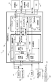
- FIG. 1 shows a configuration diagram of a vehicle system 1 according to an embodiment.
- the system 1 includes an automatic driving ECU 10, a redundant automatic driving ECU 20, a motion control ECU 30, a redundant motion control ECU 40, and an HMI (Human Machine Interface) 50.
- the outputs from the five Lidars 101, the outputs from the six Cameras 102, and the map 103 from the map distribution ECU are input to the autonomous driving ECU 10.
- Outputs from the five Radar 201 and one Camera 2 (202) are input to the redundant system automatic operation ECU 20.
- the autonomous driving ECU 10 includes a microcomputer A 112, a microcomputer B 113, a power source 104, an Ethernet switch (SW) 1 (105) (Ethernet is a registered trademark, the same applies hereinafter), an Ethernet switch (SW) 2 (106), a bus 1 (107), a bus. 2 (108), bus 3 (109), bus 4 (110), bus 5 (111), and bus 6 (114).
- SW Ethernet switch
- the microcomputer A 112 includes a surrounding recognition / trajectory generation unit 121, a function level determination unit 122, a recognition distance detection unit 123, and a failure detection unit 124.
- the microcomputer B112 includes a safe state selection unit 131, a control instruction unit 132, a failure level determination unit 133, and a failure detection unit 134.
- Each functional unit of the microcomputer A 112 and the microcomputer B 113 can be realized, for example, by the processor operating according to a program stored in the memory, or can be realized by a logic circuit corresponding to each function. 1 and 2, the word "section" of each functional section is omitted.
- the motion control ECUs 30 and 40 convert the outputs of the autonomous driving ECUs 10 and 20 into actuator inputs.
- the HMI 5 has a function of displaying the current state of the automatic driving system to the driver and receiving an instruction from the driver.
- FIG. 2 is a data flow between the functions of the vehicle system 1 according to the embodiment.
- the outputs of Radar 201 and Camera 2 (202) are input to the automatic driving ECU 20.
- the output of Lidar 101, the output of Camera 1 (102), and the map 103 are input to the failure detection unit 124 of the microcomputer A 112, and the failure determination of the elements in the Lidar 101, Camera 1 (102), the map 103 and the microcomputer A 112 is performed. For example, when there is no input from the device or error data is input, the device is determined to be defective.
- the failure detection unit 134 of the microcomputer B113 makes a failure determination of an element in the microcomputer B.
- the failure level determination unit 133 determines whether or not degeneration operation (Emergency Operation) is necessary (degeneration necessity) according to the failure location indicated by the outputs of the failure detection units 124 and 134 and the redundant system automatic operation ECU 20.
- the automatic operation ECU 20 is also equipped with a failure detection unit, and the failure detection results (failure points) of the Radar 201, the Camera 2 (202) and the automatic operation ECU 20 are input to the failure level determination unit 133.
- the recognition distance detection unit 123 is an example of a device performance determination unit that determines the performance of the device.
- the recognition distance detection unit 123 includes a sensor value of the Lidar 101, Camera 1 (102), Radar 201 and Camera 2 (202) and / or another sensor device, and a failure detection unit 124.
- the recognition distance of the recognition devices 101, 102, 201 and 202 is determined and output according to the failure location information from the redundant system automatic operation ECU 20.
- the function level determination unit 122 determines the performance display state of each of the plurality of functions.
- the performance exhibiting state indicates, for example, the vehicle recognition distance in each recognition direction and the availability of the map function.
- the function level determination unit 122 calculates the recognition distance as a vehicle from the recognition distance of each recognition device in each recognition direction, and further, speed limit, lane change limit, automatic signal stop limit, automatic right Outputs an instruction for function restriction such as left turn stop restriction.
- the speed limit indicates the maximum speed of the vehicle, and the lane change limit, automatic signal stop limit and automatic left / right turn stop limit are the automatic driving system that automatically changes the lane, automatically stops according to the signal, and automatically turns when turning left or right. Indicates that the stop will not be performed.
- the safe state selection unit 131 outputs information about the first and second target safe states (target safe state information) to the surrounding recognition / trajectory generation unit 121.
- the safe state selecting unit 131 selects the first target safe state according to the result of the decision whether the degeneration is necessary by the failure level determining unit 133 and the function restriction instruction from the function level determining unit 122.
- the safe state selecting unit 131 selects the target safe state after the timeout (second target safe state) based on the available function of the vehicle system 1. As will be described later, the available function is determined based on the vehicle recognition distance in each of the recognition directions.
- Information on the target safety status includes information on the first target safety status and the second target safety status (if necessary).
- the information on the second target safe state may be notified to the surrounding recognition / trajectory generation unit 121 after a timeout. Since the function restriction is based on the recognition distance, the selection of the target safety state is based on the necessity of degeneration and the recognition distance.
- Circumstance recognition / trajectory generation unit 121 determines the driving conditions of the vehicle.
- the traveling conditions include, for example, the trajectory of the vehicle and the target speed.
- the surrounding recognition / trajectory generation unit 121 specifies the situation around the vehicle and the current position by inputting the recognition results of the Lidar 101, the Camera 1 (102), the Radar 201, and the Camera 2 (202), and the position information and the map 103.
- the surrounding recognition / trajectory generation unit 121 generates a trajectory that satisfies the restriction from the function level determination unit 122 toward the destination or the place designated as the second target safety state by the safety state selection unit 131.
- the HMI 5 displays, for example, information such as the current recognition state around the vehicle, the presence / absence of a failure, and a target safety state.
- the control instruction unit 132 outputs a control command value according to the trajectory from the surrounding recognition / trajectory generation unit 121.
- the motion control ECUs 30 and 40 control the actuators such as the engine and the inverter by using the control command value from the control instruction unit 132 as an input.
- FIG. 3 is an example of the failure influence management table 310 according to the present embodiment.
- the failure influence management table 310 manages the influence of the failure point on the autonomous driving ECU 10.
- the failure influence management table 310 is stored in advance in the memory of the automatic driving ECU 10.
- the failure influence management table 310 includes a failure location column 311, an input column 312 of the automatic driving ECU 10, and an output column 313 of the automatic driving ECU 10.
- the failure point column 311 indicates devices that can be failure points such as a recognition device, a power supply, a microcomputer, a redundant automatic operation ECU, an Ethernet switch (SW), and a bus.
- the failure location column 311 the direction included in the name of the recognition device indicates the recognition direction.
- “map” and “route” mean that the map shows route information.
- the input column 312 indicates whether or not each failure point indicated by the failure point column 311 has an influence on the input of the automatic driving ECU 10. Inputs affected are indicated by "1". For example, when the recognition device in a certain recognition direction is out of order, the input from the recognition device in the recognition direction is affected. If the power supply 104 fails, all inputs of the autonomous driving ECU 10 will be affected.
- the output column 313 indicates whether or not each of the failure points indicated by the failure point column 311 affects the output from the automatic driving ECU 10. In the example of FIG. 3, the failure of the power supply 104, the microcomputers 112 and 113, and the specific bus affects the output from the autonomous driving ECU 10.
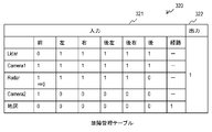
- FIG. 4 is an example of the failure management table 320 according to this embodiment.
- the failure management table 320 is stored in the memory of the automatic driving ECU 10, and is updated and managed by the failure level determination unit 133.
- the failure management table 320 manages the input and output of the autonomous driving ECU 10 affected by the failure.
- the failure management table 320 shows an input column 321 and an output column 322. Each cell indicates the number of normal operations for each of the input and output of the autonomous driving ECU 10. For example, when the Radar that recognizes the forward direction fails, the value of the cell specified in the “front” column and the “Radar” row is changed from “1” to “0”.
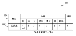
- FIG. 5 shows an example of the redundancy management table 330 according to this embodiment.
- the redundancy management table 330 is stored in the memory of the automatic driving ECU 10, and is updated and managed by the failure level determination unit 133.
- the redundancy management table 330 manages the redundancy at the input and output of the automatic driving ECU 10.
- the item row 331 shows items whose redundancy is managed. In this example, the redundancy of each of the input, route (map) and output in the six recognition directions is managed.
- the redundancy row 332 indicates the redundancy of each item. For example, when the front redundancy is reduced due to a failure of one of the recognition devices, the redundancy is reduced from "3" to "2". For example, the redundancy “2” indicates a double system.
- FIG. 6 is an example of the device recognition distance management table 340 according to this embodiment.
- the device recognition distance management table 340 is stored in the memory of the autonomous driving ECU 10, and is updated and managed by the recognition distance detection unit 123.
- the device recognition distance management table 340 manages the current recognition distance of each recognition device.
- the device recognition distance management table 340 has a device column 341 and a recognition distance column 342.
- the device column 341 indicates the type of recognition device that recognizes the surroundings of the vehicle.
- the recognition distance column 342 shows the current recognition distance by each recognition device in each recognition direction.
- the recognition distance by the recognition device may change depending on the presence or absence of a failure of the recognition device and the conditions around the vehicle (weather, road conditions, etc.). Therefore, the value of the device recognition distance management table 340 is updated at any time, for example, periodically. For example, when the radar that recognizes the front side fails, the recognition distance is changed from 200 to 0.
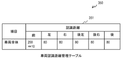
- FIG. 7 is an example of the vehicle recognition distance management table 350 according to the present embodiment.
- the vehicle recognition distance management table 350 is stored in the memory of the autonomous driving ECU 10, and is updated and managed by the function level determination unit 122.
- the vehicle recognition distance management table 350 manages the recognition distance of the entire vehicle.
- the vehicle recognition distance management table 350 has a recognition distance column 351 and indicates the current recognition distance as a vehicle in each recognition direction. In the example of FIG. 7, the vehicle recognition distance in each recognition direction is the maximum recognition distance of the recognition device in each recognition direction.
- the vehicle recognition distance management table 350 can manage the performance of the function (performance performance state) according to the presence / absence of a device failure and the performance change of the operating device.
- FIG. 8 is an example of the safe state selection table 360 according to the present embodiment.
- the safe state selection table 360 is stored in advance in the memory of the automatic driving ECU 10.
- the safe state selection table 360 is referred to for determining the first target safe state.
- the safe state selection table 360 manages the first target safe state under the restriction determined by the degeneration operation (Emergency Operation) and the function level determination unit 122.
- the safe state selection table 360 has a degeneration necessity column 361, a speed limit column 362, a first target safe state column 363, and a timeout column 364.
- the degeneration necessity column 361 indicates the necessity of degeneration operation. When the cell value is "necessary”, the degeneration operation is executed, and when the cell value is "not", the degeneration operation is not executed.
- the speed limit column 362 stores a reference value to be compared with the speed limit determined by the function level determination unit 122.
- the first target safe state column 363 shows the operation mode in the first target safe state.
- the time-out column 364 shows a time constraint in which the “driver takeover” shown in the first target safe state column 363 is determined not to be achieved.
- the safe state selection table 360 may include a function limit different from the speed limit as a condition for selecting the first target safe state. For example, it may include vehicle lane change restriction, automatic right / left stop, automatic signal stop restriction, and the like.
- the lane change restriction is an operation mode in which the lane change cannot be performed by the system alone because the recognition distance behind is reduced.
- "driver takeover" may be selected as the first target safety state.
- the first target safe state column 363 may include an operation mode different from the example shown in FIG. 8.
- the first target safe state column 363 may include a vehicle stop in a mode indicated by a safe state request function table 370 described later.
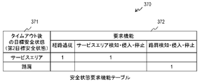
- FIG. 9 is an example of the safe state request function table 370 according to the present embodiment.
- the safe state request function table 370 is stored in advance in the memory of the automatic driving ECU 10.
- the safety state request function table 370 manages the relationship between the target safety state after the timeout (second target safety state) indicated by the safety state selection table 360 and the function required by the second target safety state.
- the safe state request function table 370 has a target safe state after timeout (second target safe state) column 371 and a required function column 372.
- the required function column 372 indicates the function required by each of the second target safety states indicated by the target safety state after timeout (second target safety state) column 371.
- FIG. 10 is an example of the function request recognition distance table 380 according to the present embodiment.
- the function request recognition distance table 380 is stored in advance in the memory of the autonomous driving ECU 10.
- the function request recognition distance table 380 manages the recognition distance required by each function indicated by the request function column 372 of the safe state request function table 370.
- the function request recognition distance table 380 has a function column 381 and a request recognition distance column 382.
- the function column 381 is associated with the required function column 372 of the safe state required function table 370.
- the required recognition distance column 382 shows the recognition distance of each recognition direction required by each function indicated by the function column 381.
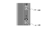
- FIG. 11 is an example of a use case according to this embodiment.
- This use case shows a situation in which the Radar in front of the vehicle 401 is out of order while the vehicle 401 is traveling on the highway with heavy rain in the automatic driving mode.
- Another vehicle 402 is traveling in front of the own vehicle.
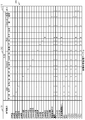
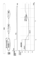
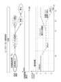
- FIG. 12 shows an example of the behavior of the vehicle 401 according to the present embodiment in the use case shown in FIG.
- FIG. 12 shows the state transition of the vehicle 401, the recognition distance, and the vehicle speed.
- the horizontal axis represents time.
- the front Radar breaks down at time T0 while automatically traveling on a heavy rain freeway at automatic driving level 3.
- the front recognition distance will be reduced from 200 meters of Radar to 10 meters of the recognition distance by the camera whose recognition distance has been reduced due to bad weather.
- the speed limit in the speed limit decreases from V0 to V2 as the front recognition distance decreases.
- the traveling speed in the automatic driving mode decreases from 100 km / h, which is slower than the speed V0, to the speed V2 (55 km / h) due to the failure of the front radar.
- the state of the vehicle 401 transitions from automatic operation to driver takeover at time T0, and further, at time T1 driver takeover is achieved and transitions to driver operation.
- FIG. 13 is an operation flow of the failure detection units 124 and 134 of the microcomputer A 112 and the microcomputer B 113.
- the failure detection units 124 and 134 monitor the failure location.
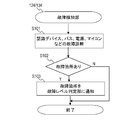
- the failure detection units 124 and 134 perform failure diagnosis of the recognition device, the bus, the power supply, the microcomputer, etc. (S101). For example, when the failure detection units 124 and 134 cannot normally receive a signal from the target location, it is determined that a failure has occurred at the target location.
- the failure detection units 124 and 134 notify the failure level determination unit 133 of the failure location (S102). If there is no failure point (S101: N), this flow ends.
- FIG. 14 is an operation flow of the failure level determination unit 133.
- the failure level determination unit 133 receives a notification of a failure location from the failure detection units 124 and 134 and the redundant system automatic operation ECU 20.
- the failure level determination unit 133 refers to the failure influence management table 310 and updates the failure management table 320 according to the notification of the failure point (S151).
- the failure level determination unit 133 updates the redundancy management table 330 based on the location affected by the failure location (the location updated in the failure management table 320), and outputs in the current configuration and in the plurality of recognition directions.
- the redundancy of each input is determined (S152).
- the failure level determination unit 133 determines whether or not the redundancy is 0 at any position indicated by the redundancy management table 330, that is, at the input or output in any recognition direction (S153).
- the failure level determination unit 133 outputs a degeneration request to the safe state selection unit 131 (S154). If the redundancy of any part is greater than 0 (S153: N), this flow ends. Note that the condition for outputting the degeneration request may be that the redundancy of any part is 1 or less. In this way, by outputting the degeneration request when the redundancy becomes equal to or less than the predetermined threshold value, it is possible to improve the safety.
- FIG. 15 is an operation flow of the control instruction unit 132.
- the control instructing unit 132 receives the information on the trajectory that the vehicle should travel from the surrounding recognition / trajectory generating unit 121, and outputs a control command value based on the trajectory to the motion control ECU 30 and the redundant system motion control ECU 40 (S201). ..
- the control instruction unit 132 stops the output when the driver takeover is achieved.
- FIG. 16 is an operation flow of the recognition distance detection unit 123.
- the recognition distance detection unit 123 according to the sensor values of the Lidar 101, Camera 1 (102), Radar 201 and Camera 2 (202) and / or other sensor devices, and the failure location information from the failure detection unit 124 and the redundant system automatic operation ECU 20,
- the recognition distances of the recognition devices 101, 102, 201 and 202 are determined (S251).
- the recognition distance detection unit 123 updates the device recognition distance management table 340 with the determined recognition distance.
- the recognition distance detection unit 123 executes the processing at any time, for example, periodically.
- the recognition distance of the recognition device becomes zero.
- the recognition distance (current performance) of the recognizing device in operation depends on the situation around the vehicle such as weather and road conditions. For example, the recognition distance may be shortened due to bad weather such as rain, fog, and snow. Alternatively, when the white line on the road is thin, the color of the traffic light is light, or the traffic light is hidden by a tree branch (bad road), the speed at which objects such as white line recognition and signal recognition can be recognized, that is, Reduce the recognition distance. Furthermore, conditions such as backlighting and night driving may also be factors that shorten the recognition distance.
- the recognition distance detection unit 123 determines the current recognition distance (current performance) based on, for example, the measurement result of the operating recognition device (recognition device that has not failed). Specifically, the recognition distance detecting unit 123 determines each recognition distance based on the data from the Lidar 101, the Camera 1 (102), the Radar 201, and the Camera 2 (202). For example, the distance (recognition distance) of an object recognizable by a stereo camera can be determined from its parallax, the recognition distance of Lidar can be determined from the reflection intensity from the recognizable object, and the recognition distance of white line recognition recognizes the white line. It can be calculated from the possible speeds.
- the recognition distance detection unit 123 may determine the recognition distance of the recognition device based on data from a sensor different from the recognition device that determines those recognition distances.
- the vehicle system 1 includes a weather sensor, and the recognition distance detection unit 123 determines the recognition distance of each recognition device previously associated with the weather detected by the weather sensor as the current recognition distance.
- the recognition distance detection unit 123 may determine the recognition distance of each recognition device based on only one of the presence or absence of a failure of the recognition device and the current performance.
- the recognition distance detection unit 123 can more appropriately determine the recognition distance of each recognition device based on both the presence / absence of a failure of the recognition device and the current performance as described above.
- FIG. 17 is an operation flow of the function level determination unit 122.
- the function level determination unit 122 makes a restriction to determine a function restriction such as speed restriction or lane change restriction based on the vehicle recognition distance in each recognition direction (S301).
- the function level determination unit 122 receives the recognition distance indicated by the device recognition distance management table 340 from the recognition distance detection unit 123.
- the function level determination unit 122 determines the vehicle recognition distance for each recognition direction based on the received recognition distance, and updates the vehicle recognition distance management table 350.
- the autonomous driving ECU 10 holds in advance information that specifies the relationship between the vehicle recognition distance in each recognition direction and each restriction.
- the function level determination unit 122 refers to the information and determines the restriction based on the vehicle recognition distance for each recognition direction.
- the recognition distance indicated by the device recognition distance management table 340 is determined based on the presence / absence of a device failure and / or the current performance of the device. Therefore, the function level determination unit 122 determines the vehicle recognition distance based on the presence / absence of a device failure and / or the current performance of the device.
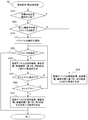
- FIG. 18 is an operation flow of the surrounding recognition / orbit generation unit 121.
- the surrounding recognition / trajectory generation unit 121 determines whether or not the target safe state information is received from the safe state selection unit 131 (S351).
- the target safety state information includes information about the first target safety state and the (required) second target safety state. If not received (S351: N), the surrounding recognition / trajectory generation unit 121, based on the recognition result of the recognition device, the map information, and the function restriction from the function level determination unit 122, the trajectory toward the destination and the target speed.
- a driving condition including the driving condition is generated (S352).
- step S353 When the target safe state information is received (S351: Y) and when the first target safe state is “running continuously” (S353: N), the surrounding recognition / trajectory generation unit 121 executes step S353. To do.
- the first target safety state is "driver takeover” (S353: Y)
- the surrounding recognition / trajectory generation unit 121 notifies the driver of takeover via the HMI 50, for example (S354).
- the surrounding recognition / trajectory generation unit 121 determines whether the driver has taken over (S355). When the driver takes over (S355: Y), this flow ends. When the driver has not taken over (S355: N), the surrounding recognition / trajectory generation unit 121 determines the trajectory toward the destination point based on the recognition result of the recognition device, the map information, and the function restriction from the function level determination unit 122. And running conditions including the target speed are generated (S356).
- the surrounding recognition / trajectory generation unit 121 executes step S356 until the driver takes over.
- the target safe state information includes a timeout condition (S357: Y) and the timeout time has elapsed (S358: Y)
- the surrounding recognition / trajectory generation unit 121 causes the surrounding recognition / trajectory generation unit 121 to recognize the recognition result of the recognition device, the map information, and the function level determination unit 122.
- the traveling conditions including the trajectory and the target speed toward the point indicated by the second target safety state are generated (S359).
- the second target safe state indicates a service area or a shoulder as a destination.
- the surrounding recognition / trajectory generation unit 121 determines the target speed based on the speed limit.
- the function restrictions include, in addition to speed restrictions, vehicle lane change restrictions, automatic right / left stop, automatic signal stop restriction, and the like.
- the surrounding recognition / track generation unit 121 notifies the driver of the lane change request by the HMI 50. After confirming the safety, the driver notifies the system of approval of the lane change via the HMI 50. The surrounding recognition / trajectory generation unit 121 changes the lane according to the driver's approval.
- the automatic right / left turn stop restriction is a state where the left and right cognitive distances have decreased.
- the surrounding recognition / trajectory generation unit 121 always stops at a pedestrian crossing when turning right or left at an intersection, and passes after obtaining a driver's passing approval.
- the surrounding recognition / trajectory generation unit 121 notifies the driver that the signal recognition is not functioning by the HMI 50. If the signal is red, the driver uses the brakes to slow down.
- the surrounding recognition / trajectory generation unit 121 can determine an appropriate traveling condition based on the function limitation and the target safe state.
- FIG. 19 is an operation flow of the safe state selection unit 131.
- the safe state selection unit 131 refers to the safe state selection table 360, and selects the first target safe state based on the presence or absence of the degeneration request from the failure level determination unit 133 and the function restriction from the function level determination unit 122. ..
- the safe state selecting unit 131 further refers to the safe state request function table 370 to select the second target safe state (S404).
- the safe state selection unit 131 refers to the function request recognition distance table 380, and determines the available function based on the vehicle recognition distance of each recognition direction received from the recognition distance detection unit 123.
- the safe state selection unit 131 refers to the safe state request function table 370 and selects the second target safe state based on the available functions. If any of the target safety states can be selected, they are selected based on a predetermined priority.
- the safety state selection unit 131 When the first target safety state is selected (S402: Y), the safety state selection unit 131 provides information about the first target safety state and the second target safety state when accompanied by the surrounding recognition / trajectory generation unit. Notify 121. If the first target safety state is not selected (S402: N), this flow ends.
- FIG. 20 shows another example of the use case according to the embodiment.
- another vehicle 402 is traveling in front of the own vehicle 401 (see FIG. 11), and further, when the own vehicle is traveling on a highway with heavy rain in the automatic driving mode, map distribution fails. Shows.
- the automatic driving ECU 10 shifts to the driver takeover mode. If the takeover succeeds at time T1 within the timeout time (time T2), the automatic driving ECU 10 shifts to the driver operation mode. If the takeover has not been achieved, the automatic driving ECU 10 selects the road shoulder as the second target safety state at time T2, and stops at the road shoulder at time T3.
- the map distribution function has a redundancy of 1 when it is normal, and a redundancy of 0 when it fails. Therefore, a degenerate operation is required.
- the first target safe state column 363 of the entry corresponding to the failure of the map distribution function is “driver takeover”, and the timeout column 364 shows the timeout time (seconds).
- the safe state selecting unit 131 selects a road shoulder as the second target safe state based on the vehicle recognition distance in each recognition direction, the function request recognition distance table 380, and the safety condition request function table 370.
- the safety state selection unit 131 notifies the surrounding recognition / trajectory generation unit 121 of the target safety state information including the above information.
- the surrounding recognition / orbit generation unit 121 receives the notification of “driver takeover” and the designation of the timeout time as the first target safety state. When the time-out time has elapsed, the handover has not been reached, and the surrounding recognition / trajectory generation unit 121 stops at the road shoulder designated as the second target safety state.
- safety is improved because the vehicle is controlled in consideration of the performance limit of the function in automatic driving.
- the present invention is not limited to the above-described embodiment, and various modifications are included.
- the above-described embodiments have been described in detail in order to explain the present invention in an easy-to-understand manner, and are not necessarily limited to those having all the configurations described.
- each of the above-mentioned components, functions, processing units, etc. may be realized in hardware by designing a part or all of them with, for example, an integrated circuit. Further, each of the above-described configurations, functions, and the like may be realized by software by a processor interpreting and executing a program that realizes each function. Information such as a program, a table, and a file that realizes each function can be placed in a memory, a hard disk, a recording device such as SSD (Solid State Drive), or a recording medium such as an IC card or an SD card.
- SSD Solid State Drive
- control lines and information lines are shown to be necessary for explanation, and not all control lines and information lines are shown on the product. In reality, it may be considered that almost all configurations are connected to each other.
- 1 vehicle system 10 automatic driving ECU, 20 redundant automatic driving ECU, 30 motion control ECU, 40 redundant motion control ECU, 50 human machine interface, 101 Lidar, 102, 202 Camera, 103 map, 201 Radar, 105 , 106 Ethernet switch, 107-114 bus, 103 map, 104 power supply, 112, 113 microcomputer, 121 surrounding recognition / orbit generation unit, 122 function level determination unit, 123 recognized distance detection unit, 124, 134 failure detection unit, 131 safety State selection unit, 132 control instruction unit, 133 failure level determination unit, 310 failure impact management table, 320 failure management table, 330 redundancy management table, 340 device recognition distance management table, 350 vehicle recognition distance management table, 360 safe state selection Table, 370 safety state request function table, 380 function request recognition distance table, 401 own vehicle, 402 other vehicle
Landscapes
- Engineering & Computer Science (AREA)
- Automation & Control Theory (AREA)
- Human Computer Interaction (AREA)
- Transportation (AREA)
- Mechanical Engineering (AREA)
- Control Of Driving Devices And Active Controlling Of Vehicle (AREA)
- Traffic Control Systems (AREA)
Abstract
本発明は、自動運転における安全性を高める。車両制御装置は、複数機能それぞれの性能発揮状態を判定する機能レベル判定部と、性能発揮状態に基づき目標安全状態を選択する安全状態選択部と、目標安全状態と性能発揮状態とに基づいて車両の軌道を含む車両の走行条件を決定する軌道生成部と、走行条件に基づいて車両を制御する制御指示部と、を含む。
Description
本発明は、車両制御装置及び車両制御方法に関するものである。
自動運転レベル3以上(SAE(Society of Automotive Engineers)定義)ではフェールオペレーショナルが必須となる。フェールオペレーショナルは、故障時に安全な場所または状況まで走行を継続し、ドライバがいる場合には引き継ぎを実施し、ドライバが不在または引き継ぎ要求に応じない時間が一定時間続いた際にはシステムが自動で安全な場所に停止する。
フェールオペレーショナルはEmergency Operationとも呼ばれる。例えば、自動運転レベル3では、故障発生によって目的地まで自動運転で到達困難な場合には、自動運転システムは運転手に車両操作の引き継ぎを依頼する。引き継ぎが達成できた場合には自動運転からマニュアル運転に切り替わり、未達成である場合には、システムが安全な場所または状況を選択し、停止する。
例えば、フェールオペレーショナルを実現する技術の一つとして、特許文献1ではデバイスの故障箇所や道路の状況に応じて、複数の安全状態候補の中から1つを選択する方法を開示している。
自動運転においては、認識性能の性能限界が発生し得る。性能限界は、認識性能の低下を意味する。例えば、悪天候(雨、雪、霧など)や悪路(白線が薄い、信号が汚れている等)等の状況及びカメラやRadarなどの認識センサの特性に応じて、認識範囲や認識精度が低下し得る。他の例において、特定方向において冗長化された認識機能における一系統の故障により、当該方向における認識範囲や認識精度が低下し得る。しかしながら、特許文献1では認識性能の性能限界を考慮していないため、安全性がより高い安全状態を選択できない可能性がある。
例えば、カメラとRadarで前方の認識機能が冗長化された自動運転システムは、Radarが故障した場合に、故障したRadarが冗長系の1系統でありカメラが使用可能であるため、走行継続で問題ないと判断する。しかしながら、例えば、走行道路が高速道路であるとすると、Radarよりも認識距離が短いカメラによる高速道路での自動運転による高速走行は、安全性を低下させる可能性がある。
他の例において、天候が大雨、走行道路が高速道路であり、特定方向における認識機能の認識距離が大雨により著しく低下している場合、高速道路での自動運転による高速走行は安全性を低下させる可能性がある。
以上のことから、従来の技術において、安全性がより高い安全状態が選択されない可能性がある。本発明は、このような課題を解決するためになされたものであり、自動運転における安全性を高めることを目的とする。
本発明の代表的な一例は、複数機能それぞれの性能発揮状態を判定する機能レベル判定部と、前記性能発揮状態に基づき目標安全状態を選択する、安全状態選択部と、前記目標安全状態と前記性能発揮状態とに基づいて、車両の軌道を含む前記車両の走行条件を決定する軌道生成部と、前記走行条件に基づいて車両を制御する制御指示部と、を含む車両制御装置である。
本発明の代表的な一例によれば、自動運転においてより高い安全性を確保できる。
以下、実施の形態を、図面を用いて説明する。以下に説明する実施の形態は特許請求の範囲にかかる発明を限定するものではなく、また実施の形態の中で説明されている特長の組み合わせの全てが発明の解決手段に必須であるとは限らない。
以下に開示される実施の形態は、自動運転システムの安全技術に関する。より具体的には、故障発生又は周囲環境に変化による性能限界を考慮して安全状態を選択する技術が開示される。本実施の形態に係る車両制御装置は、自動運転において、故障の発生、天候、又は道路状況等を考慮した安全状態を選択可能となるため、より高い安全性を確保できる。
性能限界は、認識性能の低下が発生したことを示す。例えば、周辺認識デバイスの特性上、天候条件や道路状態等によって周辺認識デバイスの性能は低下し得る。また、冗長化された周辺認識機能において、一系統の故障によりその性能が低下し得る。認識性能の状態は性能発揮状態であり、例えば、認識距離、認識精度、又は速度で表わすことができる。以下の説明においては、認識性能の低下を認識距離の低下で表現する。
例えば、認識性能の状態を表す速度は、認識距離で停止可能な速度と対応付けることができる。また、物体認識の精度の低下も、認識距離の低下で表現する。例えば、白線が薄れていて高速走行では認識困難な場合でも、低速走行であれば認識精度を向上できる。例えば、認識精度は、白線を認識して白線内を走行できる速度に対応付けることができ、その速度から車両を停止することができる距離を、当該速度に対応する認識距離としてもよい。
図1は、実施の形態に係る車両システム1の構成図を示す。システム1は、自動運転ECU10、冗長系の自動運転ECU20、運動制御ECU30、冗長系の運動制御ECU40、及びHMI(ヒューマンマシンインタフェース)50を含む。自動運転ECU10には、5台のLidar101からの出力、6台のCamera102からの出力、及び地図配信ECUからの地図103が入力される。冗長系の自動運転ECU20には、5台のRadar201及び1台のCamera2(202)それぞれからの出力が入力される。
自動運転ECU10は、マイコンA112、マイコンB113、電源104、イーサネットスイッチ(SW)1(105)(イーサネットは登録商標、以下同じ)、イーサネットスイッチ(SW)2(106)、バス1(107)、バス2(108)、バス3(109)、バス4(110)、バス5(111)、バス6(114)を含む。
マイコンA112は、周囲認知・軌道生成部121、機能レベル判定部122、認識距離検出部123、及び故障検知部124を含む。マイコンB112は、安全状態選択部131、制御指示部132、故障レベル判定部133、及び故障検知部134を含む。マイコンA112及びマイコンB113の各機能部は、例えば、プロセッサがメモリに格納されているプログラムに従って動作することで実現できる、又は、各機能に対応する論理回路で実現できる。なお、図1及び2において、各機能部の「部」の語は省略されている。
運動制御ECU30及び40は、自動運転ECU10及び20の出力を、アクチュエータの入力に変換する。HMI5は、運転手に自動運転システムの現在状態の表示や、運転手からの指示を受けつける機能を有する。
図2は実施形態に係る車両システム1の機能間のデータフローである。自動運転ECU20には、Radar201とCamera2(202)の出力が入力される。マイコンA112の故障検知部124には、Lidar101の出力、Camera1(102)の出力、地図103が入力され、Lidar101、Camera1(102)、地図103及びマイコンA112内の要素の故障判定を行う。例えば、デバイスからの入力がない又はエラーデータが入力される場合、当該デバイスは故障であると判定される。マイコンB113の故障検知部134は、マイコンB内の要素の故障判定を行う。
故障レベル判定部133は、故障検知部124、134及び冗長系自動運転ECU20の出力が示す故障箇所に応じて、縮退オペレーション(Emergency Operation)の要否(縮退要否)を判定する。本実施形態では自動運転ECU20にも故障検知部が搭載されており、Radar201、Camera2(202)及び自動運転ECU20の故障検知結果(故障箇所)が、故障レベル判定部133に入力される。
認識距離検出部123はデバイスの性能を判定するデバイス性能判定部の例であり、Lidar101、Camera1(102)、Radar201及びCamera2(202)及び/又は他のセンサデバイスのセンサ値と故障検知部124及び冗長系自動運転ECU20からの故障箇所情報に応じて、認識デバイス101、102、201及び202の認識距離を決定し、出力する。
機能レベル判定部122は、複数機能それぞれの性能発揮状態を判定する。性能発揮状態は、例えば、各認識方向の車両認識距離や地図機能の使用可否を示す。本実施形態において、機能レベル判定部122は、認識方向それぞれにおいて、各認識デバイスの認識距離から車両としての認識距離を算出し、さらに、速度制限、自動車線変更制限、自動信号停止制限、自動右左折停止制限などの機能制限の指示を出力する。速度制限は、車両の最大速度を示し、自動車線変更制限、自動信号停止制限及び自動右左折停止制限は、自動運転システムが、自動車線変更、信号に応じた自動停止、及び右左折時の自動停止を実行しないことを示す。
安全状態選択部131は、周囲認知・軌道生成部121に第1及び第2目標安全状態についての情報(目標安全状態情報)を出力する。安全状態選択部131は、故障レベル判定部133による縮退要否の判定結果と機能レベル判定部122からの機能制限指示に応じて、第1目標安全状態を選択する。第1目標安全状態にタイムアウト条件が付されている場合、安全状態選択部131は、車両システム1の利用可能機能に基づきタイムアウト後の目標安全状態(第2目標安全状態)を選択する。後述するように、利用可能機能は、認識方向方それぞれの車両認識距離に基づき決定される。
目標安全状態についての情報は、第1目標安全状態及び第2目標安全状態(必要であれば)の情報を含む。第2目標安全状態の情報は、タイムアウト後に周囲認知・軌道生成部121に通知されてもよい。機能制限は、認識距離に基づくため、目標安全状態の選択は、縮退要否及び認識距離に基づく。
周囲認知・軌道生成部121は、車両の走行条件を決定する。走行条件は、例えば、車両の軌道や目標速度を含む。周囲認知・軌道生成部121は、Lidar101、Camera1(102)、Radar201、及びCamera2(202)の認識結果、並びに、位置情報及び地図103を入力をとして、車両周辺の状況及び現在位置を特定する。周囲認知・軌道生成部121は、目的地または安全状態選択部131により第2目標安全状態として指定された場所に向けて、機能レベル判定部122からの制限を満たすような軌道を、生成する。HMI5は、例えば、現状の車両周辺の認識状況、故障の有無、目標安全状態等の情報を表示する。
制御指示部132は、周囲認知・軌道生成部121からの軌道に応じた制御指令値を出力する。運動制御ECU30及び40は、制御指示部132からの制御指令値を入力として、エンジンやインバータなどのアクチュエータを制御する。
図3は本実施形態に係る故障影響管理テーブル310の例である。故障影響管理テーブル310は、故障個所が自動運転ECU10に与える影響を管理する。故障影響管理テーブル310は、自動運転ECU10のメモリに予め格納されている。故障影響管理テーブル310は、故障個所の欄311、自動運転ECU10の入力の欄312、及び自動運転ECU10の出力の欄313を有する。
故障個所の欄311は、認識デバイス、電源、マイコン、冗長自動運転ECU、イーサスイッチ(SW)、バス等の故障個所となり得るデバイスを示す。故障個所の欄311において、認識デバイスの名称に含まれる方向は、その認識方向を示す。入力欄312において、「地図」及び「経路」は、地図が経路の情報を示すことを意味する。
入力の欄312は、故障個所の欄311が示す故障個所それぞれが、自動運転ECU10の入力に与える影響の有無を示す。影響を受ける入力は、「1」で示されている。例えば、ある認識方向の認識デバイスが故障している場合、当該認識方向における当該認識デバイスからの入力が影響を受ける。電源104が故障している場合、自動運転ECU10の全ての入力が影響を受けるECUの。出力の欄313は、故障個所の欄311が示す故障個所それぞれが、自動運転ECU10からの出力に影響を与えるか否かを示す。図3の例において、電源104、マイコン112、113、及び特定のバスの故障が、自動運転ECU10からの出力に影響を与える。
図4は本実施形態に係る故障管理テーブル320の例である。故障管理テーブル320は、自動運転ECU10のメモリに格納され、故障レベル判定部133により更新、管理される。故障管理テーブル320は、故障により影響を受けている自動運転ECU10の入力及び出力を管理する。故障管理テーブル320は、入力欄321及び出力欄322を示す。各セルは、自動運転ECU10の入力及び出力それぞれの正常動作数を示す。例えば、前方向を認識するRadarが故障すると、「前」列と「Radar」行で特定されるセルの値が「1」から「0」に変更される。
図5は本実施の形態に係る冗長度管理テーブル330の例である。冗長度管理テーブル330は、自動運転ECU10のメモリに格納され、故障レベル判定部133により更新、管理される。冗長度管理テーブル330は、自動運転ECU10の入力及び出力における冗長度を管理する。項目行331は、冗長度が管理されている項目を示す。本例において、六つの認識方向における入力、経路(地図)及び出力それぞれの冗長度が管理されている。冗長度行332は、各項目の冗長度を示す。例えば、前方の冗長度がいずれかの認識デバイスの故障によって削減された場合には、「3」から「2」に冗長度が削減される。例えば冗長度「2」は、2重系を示す。
図6は本実施の形態に係るデバイス認識距離管理テーブル340の例である。デバイス認識距離管理テーブル340は、自動運転ECU10のメモリに格納され、認識距離検出部123により更新、管理される。デバイス認識距離管理テーブル340は、各認識デバイスの現在の認識距離を管理している。デバイス認識距離管理テーブル340は、デバイス欄341及び認識距離欄342を有する。
デバイス欄341は、車両周囲を認識する認識デバイスの種類を示す。認識距離欄342は、認識方向それぞれにおける、各認識デバイスによる現在の認識距離を示す。認識デバイスによる認識距離は、認識デバイスの故障の有無や車両周囲の状況(天候や道路状態等)によって変化し得る。したがって、デバイス認識距離管理テーブル340の値は、随時、例えば定期的に更新される。例えば、前方を認識するRadarが故障すると、その認識距離が、200から0に変更される。
図7は本実施の形態に係る車両認識距離管理テーブル350の例である。車両認識距離管理テーブル350は、自動運転ECU10のメモリに格納され、機能レベル判定部122により更新、管理される。車両認識距離管理テーブル350は、車両全体の認識距離を管理している。車両認識距離管理テーブル350は、認識距離欄351を有し、認識方向それぞれにおける車両としての現在の認識距離を示す。図7の例において、各認識方向における車両認識距離は、各認識方向における認識デバイスの最大認識距離である。
例えば、前方の認識デバイスが全て正常に動作している場合、Radarの認識距離が最大であり、その値は200である。したがって、前方の車両認識距離は200である。前方を認識するRadarが故障すると、前方の認識デバイスの最大認識距離は、200から10に変化する。したがって、前方の車両認識距離も200から10に変更される。このように、車両認識距離管理テーブル350は、デバイスの故障の有無や動作中デバイスに性能変化に応じた機能の性能(性能発揮状態)を管理できる。
図8は本実施の形態に係る安全状態選択テーブル360の例である。安全状態選択テーブル360は、自動運転ECU10のメモリに予め格納されている。安全状態選択テーブル360は、第1目標安全状態を決定するために参照される。安全状態選択テーブル360は、縮退オペレーション(Emergency Operation)及び機能レベル判定部122に決定される制限下における第1目標安全状態を管理する。安全状態選択テーブル360は、縮退要否欄361、速度制限欄362、第1目標安全状態欄363、及びタイムアウト欄364を有する。
縮退要否欄361は、縮退オペレーションの要否を示す。セルの値が「要」の際に、縮退オペレーションが実行され、セルの値が「否」の際には、縮退オペレーションは実行されない。速度制限欄362は、機能レベル判定部122に決定される速度制限との比較される参照値を格納している。
第1目標安全状態欄363は、第1目標安全状態である動作モードを示す。タイムアウト欄364は、第1目標安全状態欄363が示す「ドライバ引き継ぎ」が未達成と判定される時間制約を示している。
安全状態選択テーブル360は、第1目標安全状態を選択する条件として、制限速度と異なる機能制限を含んでもよい。例えば、自動車線変更制限、自動右左折停止、自動信号停止制限等を含むことができる。例えば、自動車線変更制限は、後方の認識距離が低下し、システム単独では車線変更を行えない動作モードである。目的地まで到達するために車線変更が必要な場合、第1目標安全状態として「ドライバ引き継ぎ」が選択されてもよい。第1目標安全状態欄363は、図8に示す例と異なる動作モードを含んでよい。例えば、第1目標安全状態欄363は、後述する安全状態要求機能テーブル370が示す態様の車両停止を含んでもよい。
図9は本実施の形態に係る安全状態要求機能テーブル370の例である。安全状態要求機能テーブル370は、自動運転ECU10のメモリに予め格納されている。安全状態要求機能テーブル370は、安全状態選択テーブル360が示すタイムアウト後の目標安全状態(第2目標安全状態)と、第2目標安全状態が要求する機能との関係を管理する。安全状態要求機能テーブル370は、タイムアウト後の目標安全状態(第2目標安全状態)欄371及び要求機能欄372を有する。要求機能欄372は、タイムアウト後の目標安全状態(第2目標安全状態)欄371が示す第2目標安全状態それぞれが要求する機能を示す。
図10は本実施の形態に係る機能要求認識距離テーブル380の例である。機能要求認識距離テーブル380は、自動運転ECU10のメモリに予め格納されている。機能要求認識距離テーブル380は、安全状態要求機能テーブル370の要求機能欄372が示す機能それぞれが要求する認識距離を管理する。機能要求認識距離テーブル380は、機能欄381及び要求認識距離欄382を有する。機能欄381は、安全状態要求機能テーブル370の要求機能欄372に対応付けられている。要求認識距離欄382は、機能欄381が示す機能それぞれが要求する、認識方向それぞれの認識距離を示す。
図11は本実施の形態に係るユースケースの例である。本ユースケースは自車401が大雨の高速道路を自動運転モードで走行中に、前方のRadarが故障している状況を示している。自車の前方には他車402が走行している。
図12は、図11に示すユースケースにおける、本実施の形態に係る車両401の振る舞いの例を示している。図12は、車両401の状態遷移、認識距離、車両速度を示す。横軸は時間を示す。大雨の高速道路を自動運転レベル3で自動走行中に、時刻T0において前方Radarが故障する。
これにより、前方認識距離が、Radarの200mから、悪天候により認識距離が低下したカメラによる認識距離10mに低下する。さらに、前方認識距離の低下に伴い、速度制限における制限速度がV0からV2に低下する。自動運転モードにおける走行速度は、前方Radarの故障により、速度V0より遅い100km/hから速度V2(55km/h)に低下する。これに伴い、車両401の状態は、自動運転から時刻T0でドライバ引き継ぎに遷移し、さらに、時刻T1でドライバ引き継ぎが達成されてドライバ運転に遷移する。
以降より、本実施の形態に係る動作フローの詳細を説明する。図13は、マイコンA112及びマイコンB113の故障検知部124及び134の動作フローである。故障検知部124及び134は、故障個所を監視している。以下、図13の各ステップについて説明する。故障検知部124及び134は、それぞれ、認識デバイス、バス、電源、マイコン等の故障診断を行う(S101)。例えば、故障検知部124及び134は対象箇所から正常に信号を受信できない場合、当該対象箇所において故障が発生していると判定する。
いずれか1以上の箇所で故障が発生している場合(S101:Y)、故障検知部124及び134は、故障個所を故障レベル判定部133に通知する(S102)。故障箇所がない場合(S101:N)、本フローは終了する。
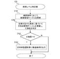
図14は故障レベル判定部133の動作フローである。以下、図14の各ステップについて説明する。故障レベル判定部133は、故障検知部124及び134、並びに、冗長系自動運転ECU20から故障箇所の通知を受ける。故障レベル判定部133は、故障影響管理テーブル310を参照し、故障個所の通知に応じて故障管理テーブル320を更新する(S151)。
故障レベル判定部133は、故障箇所に影響を受けた箇所(故障管理テーブル320において更新された箇所)に基づいて、冗長度管理テーブル330を更新し、現在の構成における出力及び複数の認識方向における入力それぞれの冗長度を判定する(S152)。故障レベル判定部133は、冗長度管理テーブル330が示すいずれかの箇所、つまり、いずれか認識方向における入力又は出力において、冗長度が0であるか否かを判定する(S153)。
冗長度管理テーブル330が示すいずれかの箇所の冗長度が0である場合(S153:Y)、故障レベル判定部133は、安全状態選択部131に縮退要求を出力する(S154)。いずれの箇所の冗長度も0より大きい場合(S153:N)、本フローは終了する。なお、縮退要求を出力する条件は、いずれかの箇所の冗長度が1以下であることであってもよい。このように、冗長度が所定の閾値以下となる場合に縮退要求を出力することで、安全性を高めることができる。
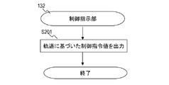
図15は制御指示部132の動作フローである。以下、図15の各ステップについて説明する。制御指示部132は、周囲認知・軌道生成部121から車両が進むべき軌道の情報を受信し、当該軌道に基づいた制御指令値を、運動制御ECU30及び冗長系運動制御ECU40に出力する(S201)。制御指示部132は、ドライバ引き継ぎが達成されると出力を停止する。
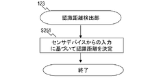
図16は認識距離検出部123の動作フローである。以下、図16の各ステップについて説明する。認識距離検出部123はLidar101、Camera1(102)、Radar201及びCamera2(202)及び/又は他のセンサデバイスのセンサ値と故障検知部124及び冗長系自動運転ECU20からの故障箇所情報とに応じて、認識デバイス101、102、201及び202の認識距離を決定する(S251)。認識距離検出部123は、決定した認識距離によって、デバイス認識距離管理テーブル340を更新する。認識距離検出部123は、当該処理を随時、例えば、定期的に実行する。
上述のように、認識デバイスが故障すると、当該認識デバイスの認識距離は0となる。また、動作中の認識デバイスの認識距離(現在性能)は、天候や道路状態といった、車両周囲の状況に依存する。例えば、認識距離は、雨、霧、雪といった悪天候によって認識距離が短くなり得る。または、道路の白線が薄くなっている、信号機の色が薄い、信号機が木の枝で隠れているといった状況(悪路)は、白線認識や信号認識などの物体を認識可能な速度、つまり、認識距離を低下させる。さらに、逆光、夜間走行などの条件も、認識距離が短くなる要因となり得る。
認識距離検出部123は、例えば、動作中認識デバイス(故障していない認識デバイス)の測定結果に基づき、現在の認識距離(現在の性能)を決定する。具体的には、認識距離検出部123は、Lidar101、Camera1(102)、Radar201及びCamera2(202)からのデータに基づき、それぞれの認識距離を決定する。例えば、ステレオカメラにより認識可能な物体の距離(認識距離)はその視差から決定でき、Lidarの認識距離は、認識可能な物体からの反射強度から決定でき、白線認識の認識距離は当該白線を認識可能な速度から計算できる。
認識距離検出部123は、それらの認識距離を決定する認識デバイスと異なるセンサからのデータに基づき、認識デバイスの認識距離を決定してもよい。例えば、車両システム1は天気センサを含み、認識距離検出部123は、天気センサにより検出された天気に予め対応付けられている各認識デバイスの認識距離を、現在の認識距離と決定する。認識距離検出部123は、認識デバイスの故障の有無及び現在の性能の一方のみに基づき、各認識デバイスの認識距離を決定してもよい。認識距離検出部123は、上述のように認識デバイスの故障の有無及び現在の性能の双方に基づき各認識デバイスの認識距離をより適切に決定できる。
図17は機能レベル判定部122の動作フローである。以下、図17の各ステップについて説明する。機能レベル判定部122は、認識方向それぞれの車両認識距離に基づき、速度制限、車線変更制限などの機能制限を決定する制約(S301)。機能レベル判定部122は、認識距離検出部123から、デバイス認識距離管理テーブル340が示す認識距離を受信する。機能レベル判定部122は、受信した認識距離に基づき認識方向それぞれ車両認識距離を決定し、車両認識距離管理テーブル350を更新する。自動運転ECU10は、認識方向それぞれの車両認識距離と制限それぞれとの関係を特定する情報を予め保持している。機能レベル判定部122は、当該情報を参照して、認識方向それぞれ車両認識距離に基づいて、制限を決定する。
上述のように、デバイス認識距離管理テーブル340が示す認識距離は、デバイスの故障の有無及び/又はデバイスの現在性能に基づき決定されている。従って、機能レベル判定部122は、デバイスの故障の有無及び/又はデバイスの現在性能に基づき車両認識距離を決定している。
図18は周囲認知・軌道生成部121の動作フローである。以下、図18の各ステップについて説明する。周囲認知・軌道生成部121は、安全状態選択部131から目標安全状態情報を受信したか判定する(S351)。目標安全状態情報は、第1目標安全状態及び(必要な)第2目標安全状態についての情報を含む。受信していない場合(S351:N)、周囲認知・軌道生成部121は、認識デバイスの認知結果、地図情報、機能レベル判定部122からの機能制限に基づき、目的地点に向けた軌道及び目標速度含む走行条件を生成する(S352)。
目標安全状態情報を受信している場合(S351:Y)、かつ、第1目標安全状態が「走行継続」である場合(S353:N)、周囲認知・軌道生成部121は、ステップS353を実行する。第1目標安全状態が「ドライバ引き継ぎ」である場合(S353:Y)、周囲認知・軌道生成部121は、例えばHMI50を介して、ドライバに引き継ぎを通知する(S354)。
周囲認知・軌道生成部121は、ドライバによる引き継ぎがなされたか判定する(S355)。ドライバによる引き継ぎがなされた場合(S355:Y)、本フローは終了する。ドライバによる引き継ぎがなされていない場合(S355:N)、周囲認知・軌道生成部121は、認識デバイスの認知結果、地図情報、機能レベル判定部122からの機能制限に基づき、目的地点に向けた軌道及び目標速度含む走行条件を生成する(S356)。
目標安全状態情報がタイムアウト条件、つまり、第2目標安全状態を含まない場合(S357:N)、周囲認知・軌道生成部121は、ドライバによる引き継ぎがあるまでステップS356を実行する。目標安全状態情報がタイムアウト条件を含み(S357:Y)、タイムアウト時間の経過した場合(S358:Y)、周囲認知・軌道生成部121は、認識デバイスの認知結果、地図情報、機能レベル判定部122からの機能制限に基づき、第2目標安全状態が示す地点に向けた軌道及び目標速度含む走行条件を生成する(S359)。図9に示す安全状態要求機能テーブル370の例において、第2目標安全状態はサービスエリア又は路肩を目的地として示す。
機能制限に応じた周囲認知・軌道生成部121の処理の例を説明する。周囲認知・軌道生成部121は、速度制限に基づき、目標速度を決定する。機能制限は、速度制限の他に、自動車線変更制限、自動右左折停止、自動信号停止制限等を含む。
例えば、自動車線変更制限において、周囲認知・軌道生成部121は、車線変更要求をドライバにHMI50により通知する。ドライバは安全確認後に、HMI50を介してシステムに車線変更の承認を通知する。周囲認知・軌道生成部121は、ドライバの承認に応じて車線を変更する。
自動右左折停止制限は、左右の認知距離が低下した状態である。例えば、周囲認知・軌道生成部121は、交差点を右折または左折する際に、横断歩道で必ず停止し、ドライバの通過承認を得てから通過する。自動信号停止制限では、例えば、周囲認知・軌道生成部121は、ドライバに信号機認識が機能していないことをHMI50により伝える。信号が赤の場合、ドライバは、ブレーキを用いて減速する。上述のように、周囲認知・軌道生成部121は、機能制限と目標安全状態に基づき、適切な走行条件を決定できる。
図19は安全状態選択部131の動作フローである。以下、図19の各ステップについて説明する。安全状態選択部131は、安全状態選択テーブル360を参照し、故障レベル判定部133からの縮退要求の有無と機能レベル判定部122からの機能制限とに基づいて、第1目標安全状態を選択する。安全状態選択部131は、選択した第1目標安全状態にタイムアウトの条件が付されている場合、さらに、安全状態要求機能テーブル370を参照して、第2目標安全状態を選択する(S404)。
具体的には、安全状態選択部131は、機能要求認識距離テーブル380を参照し、認識距離検出部123から受信した認識方向それぞれの車両認識距離に基づき、利用可能な機能を決定する。安全状態選択部131は、安全状態要求機能テーブル370を参照し、利用可能な機能に基づき第2目標安全状態を選択する。いずれの目標安全状態も選択できる場合、予め定められた優先度に基づき選択される。
安全状態選択部131は、第1目標安全状態を選択している場合(S402:Y)、第1目標安全状態及び付随する場合には第2目標安全状態の情報を、周囲認知・軌道生成部121に通知する。第1目標安全状態が選択されていない場合(S402:N)、本フローは終了する。
図20は実施の形態に係るユースケースの他の例である。本ユースケースは、自車401の前方には他車402が走行しており(図11参照)、さらに、自車が大雨の高速道路を自動運転モードで走行中に地図配信が故障する状況を示している。時刻T0において地図配信故障が発生すると、自動運転ECU10はドライバ引き継ぎモードに移行する。タイムアウト時間(時刻T2)内の時刻T1に引き継ぎが成功すれば、自動運転ECU10はドライバ運転モードに遷移する。引き継ぎが未達成の場合には、自動運転ECU10は時刻T2において第2目標安全状態として路肩を選択し、時刻T3において路肩に停止する。
地図配信機能は正常時に冗長度1であり、その故障に冗長度は0になる。従って、縮退オペレーションが必要である。安全状態選択テーブル360において、地図配信機能の故障に対応するエントリの第1目標安全状態欄363は、「ドライバ引き継ぎ」であり、タイムアウト欄364はタイムアウト時間(秒)を示す。安全状態選択部131は、認識方向それぞれの車両認識距離、機能要求認識距離テーブル380及び安全状態要求機能テーブル370に基づき、第2目標安全状態として路肩を選択する。安全状態選択部131は、上記情報を含む目標安全状態情報を周囲認知・軌道生成部121に通知する。
周囲認知・軌道生成部121は第1目標安全状態として「ドライバ引き継ぎ」の通知及びタイムアウト時間の指定を受信する。タイムアウト時間が経過時に引き継ぎが未達であり、周囲認知・軌道生成部121は第2目標安全状態として指定された路肩に停止する。
以上のように、本実施の形態によると、自動運転において機能の性能限界を考慮して車両が制御されるため、安全性が向上する。
なお、本発明は上記した実施の形態に限定されるものではなく、様々な変形例が含まれる。例えば、上記した実施の形態は本発明を分かりやすく説明するために詳細に説明したものであり、必ずしも説明したすべての構成を備えるものに限定されるものではない。また、ある構成例の一部を他の構成例の一部に置き換えることが可能であり、また、ある構成例に他の構成例を加えることも可能である。また、各構成例について、追加・削除・置換をすることが可能である。
また、上記の各構成・機能・処理部等は、それらの一部又は全部を、例えば集積回路で設計する等によりハードウェアで実現してもよい。また、上記の各構成、機能等は、プロセッサがそれぞれの機能を実現するプログラムを解釈し、実行することによりソフトウェアで実現してもよい。各機能を実現するプログラム、テーブル、ファイル等の情報は、メモリや、ハードディスク、SSD(Solid State Drive)等の記録装置、または、ICカード、SDカード等の記録媒体に置くことができる。
また、制御線や情報線は説明上必要と考えられるものを示しており、製品上必ずしもすべての制御線や情報線を示しているとは限らない。実際には殆どすべての構成が相互に接続されていると考えてもよい。
1 車両システム、10 自動運転ECU、20 冗長系の自動運転ECU、30 運動制御ECU、40 冗長系の運動制御ECU、50 ヒューマンマシンインタフェース、101 Lidar、102、202 Camera、103 地図、201 Radar、105、106 イーサネットスイッチ、107-114 バス、103 地図、104 電源、112、113 マイコン、121 周囲認知・軌道生成部、122 機能レベル判定部、123 認識距離検出部、124、134 故障検知部、131 安全状態選択部、132 制御指示部、133 故障レベル判定部、310 故障影響管理テーブル、320 故障管理テーブル、330 冗長度管理テーブル、340 デバイス認識距離管理テーブル、350 車両認識距離管理テーブル、360 安全状態選択テーブル、370 安全状態要求機能テーブル、380 機能要求認識距離テーブル、401 自車、402 他車
Claims (10)
- 複数機能それぞれの性能発揮状態を判定する機能レベル判定部と、
前記性能発揮状態に基づき目標安全状態を選択する、安全状態選択部と、
前記目標安全状態と前記性能発揮状態とに基づいて、車両の軌道を含む前記車両の走行条件を決定する軌道生成部と、
前記走行条件に基づいて車両を制御する制御指示部と、を含む車両制御装置。 - 請求項1に記載の車両制御装置であって、
前記機能レベル判定部は、前記複数機能を実現するデバイスの故障の有無に基づき前記性能発揮状態を判定する、車両制御装置。 - 請求項1に記載の車両制御装置であって、
前記機能レベル判定部は、前記複数機能を実現している動作中デバイスそれぞれの現在の性能に基づき前記性能発揮状態を判定する、車両制御装置。 - 請求項3に記載の車両制御装置であって、
前記動作中デバイスそれぞれの現在の性能を判定するデバイス性能判定部をさらに含み、
前記デバイス性能判定部は、前記動作中デバイスそれぞれによる測定結果に基づき前記動作中デバイスそれぞれの現在の性能を判定する、車両制御装置。 - 請求項1に記載の車両制御装置であって、
前記機能レベル判定部は、前記複数機能を実現する機能デバイスの故障の有無、及び、前記機能デバイスのうち故障していない動作中デバイスそれぞれの現在の性能、に基づき前記性能発揮状態を判定する、車両制御装置。 - 請求項1に記載の車両制御装置であって、
前記複数機能は複数方向における認識機能を含み、前記認識機能の性能発揮状態は認識距離で表わすことができる、車両制御装置。 - 請求項1に記載の車両制御装置であって、
前記機能レベル判定部は、前記性能発揮状態に基づき機能制限を決定し、
前記軌道生成部は、前記機能制限に基づき前記走行条件を決定する、車両制御装置。 - 請求項1に記載の車両制御装置であって、
前記複数機能を実現するデバイスの故障の有無に基づき前記複数機能それぞれの冗長度を決定し、前記冗長度に基づき縮退オペレーションの要否を決定する、故障レベル判定部をさらに含み、
前記安全状態選択部は、前記縮退オペレーションの要否に基づき前記目標安全状態を選択する、車両制御装置。 - 請求項1に記載の車両制御装置であって、
前記目標安全状態はドライバ引き継ぎであり、
前記安全状態選択部は、前記ドライバ引き継ぎが所定時間内に達成されない場合の第2安全状態をさらに選択する、車両制御装置。 - 複数機能それぞれの性能発揮状態を判定し、
前記性能発揮状態に基づき目標安全状態を選択し、
前記目標安全状態と前記性能発揮状態とに基づいて、車両の軌道を含む前記車両の走行条件を決定し、
前記走行条件に基づいて車両を制御する、ことを含む車両制御方法。
Priority Applications (1)
| Application Number | Priority Date | Filing Date | Title |
|---|---|---|---|
| DE112019005243.8T DE112019005243T5 (de) | 2018-11-19 | 2019-11-05 | Fahrzeugsteuervorrichtung und fahrzeugsteuerverfahren |
Applications Claiming Priority (2)
| Application Number | Priority Date | Filing Date | Title |
|---|---|---|---|
| JP2018216560A JP7198056B2 (ja) | 2018-11-19 | 2018-11-19 | 車両制御装置及び車両制御方法 |
| JP2018-216560 | 2018-11-19 |
Publications (1)
| Publication Number | Publication Date |
|---|---|
| WO2020105408A1 true WO2020105408A1 (ja) | 2020-05-28 |
Family
ID=70773495
Family Applications (1)
| Application Number | Title | Priority Date | Filing Date |
|---|---|---|---|
| PCT/JP2019/043183 Ceased WO2020105408A1 (ja) | 2018-11-19 | 2019-11-05 | 車両制御装置及び車両制御方法 |
Country Status (3)
| Country | Link |
|---|---|
| JP (1) | JP7198056B2 (ja) |
| DE (1) | DE112019005243T5 (ja) |
| WO (1) | WO2020105408A1 (ja) |
Cited By (2)
| Publication number | Priority date | Publication date | Assignee | Title |
|---|---|---|---|---|
| WO2021240885A1 (ja) * | 2020-05-29 | 2021-12-02 | 日立Astemo株式会社 | 電子制御装置 |
| JP2024030868A (ja) * | 2022-08-25 | 2024-03-07 | トヨタ自動車株式会社 | 車両制御装置、車両制御方法及び車両制御用コンピュータプログラム |
Families Citing this family (4)
| Publication number | Priority date | Publication date | Assignee | Title |
|---|---|---|---|---|
| JP2022149043A (ja) * | 2021-03-25 | 2022-10-06 | いすゞ自動車株式会社 | 運転制御装置 |
| JP7632125B2 (ja) * | 2021-06-30 | 2025-02-19 | トヨタ自動車株式会社 | 車両運転支援装置 |
| US20240326839A1 (en) * | 2021-10-15 | 2024-10-03 | Sony Group Corporation | Information processing device, information processing method, and program |
| FR3129911A1 (fr) * | 2021-12-06 | 2023-06-09 | Psa Automobiles Sa | Procédé et dispositif de contrôle d’un système d’aide à la conduite |
Citations (3)
| Publication number | Priority date | Publication date | Assignee | Title |
|---|---|---|---|---|
| JPH1194946A (ja) * | 1997-07-23 | 1999-04-09 | Denso Corp | 車両用障害物認識装置 |
| JP2017165296A (ja) * | 2016-03-17 | 2017-09-21 | 株式会社日立製作所 | 自動運転制御システム |
| WO2017208416A1 (ja) * | 2016-06-02 | 2017-12-07 | 三菱電機株式会社 | 移動体制御装置、移動体制御方法及び移動体制御プログラム |
Family Cites Families (1)
| Publication number | Priority date | Publication date | Assignee | Title |
|---|---|---|---|---|
| DE102014221682A1 (de) | 2014-10-24 | 2016-04-28 | Robert Bosch Gmbh | Verfahren und Vorrichtung zum Betreiben eines Fahrzeugs |
-
2018
- 2018-11-19 JP JP2018216560A patent/JP7198056B2/ja active Active
-
2019
- 2019-11-05 DE DE112019005243.8T patent/DE112019005243T5/de active Pending
- 2019-11-05 WO PCT/JP2019/043183 patent/WO2020105408A1/ja not_active Ceased
Patent Citations (3)
| Publication number | Priority date | Publication date | Assignee | Title |
|---|---|---|---|---|
| JPH1194946A (ja) * | 1997-07-23 | 1999-04-09 | Denso Corp | 車両用障害物認識装置 |
| JP2017165296A (ja) * | 2016-03-17 | 2017-09-21 | 株式会社日立製作所 | 自動運転制御システム |
| WO2017208416A1 (ja) * | 2016-06-02 | 2017-12-07 | 三菱電機株式会社 | 移動体制御装置、移動体制御方法及び移動体制御プログラム |
Cited By (5)
| Publication number | Priority date | Publication date | Assignee | Title |
|---|---|---|---|---|
| WO2021240885A1 (ja) * | 2020-05-29 | 2021-12-02 | 日立Astemo株式会社 | 電子制御装置 |
| JP2021187324A (ja) * | 2020-05-29 | 2021-12-13 | 日立Astemo株式会社 | 電子制御装置 |
| JP7397759B2 (ja) | 2020-05-29 | 2023-12-13 | 日立Astemo株式会社 | 電子制御装置 |
| JP2024030868A (ja) * | 2022-08-25 | 2024-03-07 | トヨタ自動車株式会社 | 車両制御装置、車両制御方法及び車両制御用コンピュータプログラム |
| JP7874481B2 (ja) | 2022-08-25 | 2026-06-16 | トヨタ自動車株式会社 | 車両制御装置、車両制御方法及び車両制御用コンピュータプログラム |
Also Published As
| Publication number | Publication date |
|---|---|
| JP2020082855A (ja) | 2020-06-04 |
| DE112019005243T5 (de) | 2021-07-08 |
| JP7198056B2 (ja) | 2022-12-28 |
Similar Documents
| Publication | Publication Date | Title |
|---|---|---|
| JP7198056B2 (ja) | 車両制御装置及び車両制御方法 | |
| JP6611664B2 (ja) | 自動運転制御装置および自動運転制御方法 | |
| JP7610340B2 (ja) | プロセッサおよび自律マシンの軌道を選択することをプロセッサによって実行する方法 | |
| US10745006B2 (en) | Managing automated driving complexity of the forward path using perception system measures | |
| US11987266B2 (en) | Distributed processing of vehicle sensor data | |
| US20230202504A1 (en) | Dynamic route information interface | |
| EP3359436B1 (en) | Method and system for operating autonomous driving vehicles based on motion plans | |
| US20220017107A1 (en) | Electronic control device and in-vehicle device | |
| US11125572B2 (en) | Electronic control device for autonomous driving of a vehicle | |
| CN113302109A (zh) | 实施自主车辆的回退行为的系统 | |
| KR102263955B1 (ko) | 적어도 부분 자율 자동차용 제어 시스템의 구성 | |
| JP2023065279A (ja) | 自律システムのための譲るシナリオのエンコード | |
| US11521437B2 (en) | In-vehicle device, information processing method, and computer readable medium | |
| WO2023228781A1 (ja) | 処理システム及び情報提示装置 | |
| US20210080969A1 (en) | Controlling an automated vehicle using visual anchors | |
| US20250206343A1 (en) | Method For Determining Control Parameters For Driving A Vehicle | |
| US12024183B2 (en) | Vehicle control device and recording medium | |
| CN117279818A (zh) | 一种控制方法、装置和交通工具 | |
| CN117321653A (zh) | 电子控制装置和控制方法 | |
| US12091024B1 (en) | Anticipatory vehicle seat actuation | |
| JP7658386B2 (ja) | 車両用報知制御装置及び車両用報知制御方法 | |
| US20240338331A1 (en) | Autarchical power domains for executing minimal risk conditions | |
| WO2020044891A1 (ja) | 車両制御装置及び車両制御システム | |
| WO2024009630A1 (ja) | 車両制御装置 | |
| KR20240073259A (ko) | 자율주행을 위한 mrm(최소위험동작) 장치와 방법 및 mrm 모드 결정 방법 |
Legal Events
| Date | Code | Title | Description |
|---|---|---|---|
| 121 | Ep: the epo has been informed by wipo that ep was designated in this application |
Ref document number: 19887666 Country of ref document: EP Kind code of ref document: A1 |
|
| 122 | Ep: pct application non-entry in european phase |
Ref document number: 19887666 Country of ref document: EP Kind code of ref document: A1 |